

Page 1
Revised 31/05/2013
READ THIS MANUAL BEFORE OPERATING MACHINE
DEATH, PERSONAL INJURY AND/OR PROPERTY DAMAGE MAY OCCUR UNLESS INSTRUCTIONS IN THIS MANUAL ARE FOLLOWED
NOTE: Bring this Manual when Service & or Warranty work is required.
RIDE-ON MOWER
OWNER/OPERATORS MANUAL
Model A15713A
C1632BU-16.5hp Briggs & Stratton 805mm (32”) Cut
C1638BU-16.5hp Briggs & Stratton 960mm (38”) Cut
C1932BU-19.5hp Briggs & Stratton 805mm (32”) Cut
C1938BU-19.5hp Briggs & Stratton 960mm (38”) Cut
Model A15813A
C1632HU-16.0hp Honda 960mm (32”) Cut
C1638HU-16.0hp Honda 960mm (38”) Cut
Model A15913A
C1632BRBU-16.5hp Briggs & Stratton 805mm (32”) Cut Rear Bagger
Page 2

31 May 2013
Page 2
OWNERS MANUAL FOR MODELS A15713A & A15813A
NOTES:
___________________________________________________________
___________________________________________________________
___________________________________________________________
___________________________________________________________
___________________________________________________________
___________________________________________________________
___________________________________________________________
___________________________________________________________
___________________________________________________________
___________________________________________________________
___________________________________________________________
___________________________________________________________
___________________________________________________________
___________________________________________________________
___________________________________________________________
___________________________________________________________
___________________________________________________________
___________________________________________________________
___________________________________________________________
___________________________________________________________
___________________________________________________________
___________________________________________________________
___________________________________________________________
___________________________________________________________
___________________________________________________________
___________________________________________________________
___________________________________________________________
___________________________________________________________
___________________________________________________________
___________________________________________________________
___________________________________________________________
___________________________________________________________
___________________________________________________________
___________________________________________________________
___________________________________________________________
___________________________________________________________
___________________________________________________________
___________________________________________________________
___________________________________________________________
___________________________________________________________
Page 3

31 May 2013
Page 3
OWNERS MANUAL FOR MODELS A15713A & A15813A
ISSUED TO:
ISSUED BY:
OWNERS INFORMATION
COX MODEL NO: _________________________________
COX INVENTORY CODE NO: ________________________
COX SERIAL NO:_______________________
Located on Label inside Transmission Housing
B&S ENGINE MODEL NO:______________TYPE:____________ CODE:_______________
Located on Engine refer Engine Owners Manual
HONDA ENGINE MODEL NO:____________SERIAL NO:_______________
Located on Engine refer Engine Owners Manual
DATE OF PURCHASE:__________________________________
OWNERS NAME:
ADDRESS:
TOWN/CITY:
STATE:
AUTHORISED COX DEALER/
DISTRIBUTOR:
ADDRESS:
TOWN/CITY:
STATE:
PRE DELIVERY CHECK LIST
Check parts Assemble Service Instruction
ALWAYS KEEP THIS MANUAL IN A SAFE PLACE.
Page 4

31 May 2013
Page 4
OWNERS MANUAL FOR MODELS A15713A & A15813A
Read, understand, & follow all instructions in the
Owner/Operators manual.
Know the controls and how to stop the engine
quickly in an emergency.
Allow only responsible adults, who are familiar with
the instructions in this manual, to operate the machine.
Clear the area to be mowed of loose objects such as
sticks, stones, bones, wire, toys, debris, etc., which
could be picked up and thrown by the blades.
DO NOT mow whilst people, especially children, or
pets are in the mowing area.
DO NOT mow either direction on slopes beyond 15
degrees, (1 in 3.75), (27%).
Exercise extreme caution on slopes.
Reduce speed on slopes and in sharp turns to pre-
vent overturning or loss of control.
Start or stop slowly when on slopes.
Mow up and down slopes, not across the slope.
Stay alert for holes or bumps in the terrain and other
hidden hazards.
Use care when pulling loads-
a] Use only approved hitch point;
b] limit loads to those you can safely control;
c] Do not turn sharply;
d] use care when backing up.
Watch out for traffic when crossing or operating the
mower near roadways.
Stop the blades rotating before crossing surfaces
other than grass.
When using attachments, never direct discharge of
material toward bystanders nor allow anyone near
the machine while it is in operation.
Before leaving the operators position-
a] Disengage all clutches and secure cutting units;
b] Return drive pedal to neutral position and set the
parking brake;
c] Stop the engine and remove the key.
Disengage drive to attachments and stop engine-
a] Before refueling.
b] Before removing grass-catcher;
c] Before clearing blockages from chute;
d] Before checking, cleaning or working on the
mower;
e] After striking a foreign object (check the mower
for damage and make repairs before restarting and
operating the equipment);
f] If machine starts to vibrate abnormally (check immediately).
Disengage drive to attachments when transporting or
not in use.
A mower operator should be in good physical and
mental health and not under the influence of alcohol
or any drug which might impair vision, co-ordination
or judgment.
Never mow while barefoot or wearing open sandals
or thongs. Wear long trousers and heavy shoes.
It is advisable to wear suitable eye protection when
operating a mower.
Mow only in daylight or good artificial light.
Before using, always visually inspect to see that
blades, bolts and cutter assembly are not worn or
damaged. Replace worn or damaged blades and
bolts in sets to preserve balance.
Check all nuts, bolts, and screws often; always be
sure the mower is in safe operating condition.
Keep safety devices (guards and switches) in place
and in working order.
Never use the mower unless the grass catcher, or
guards provided by the manufacturer, are in position.
Ensure any replacement parts used comply with the
original manufacture’s recommendations and specifi-
cations.
Replace worn or faulty silencers.
Keep machine free of grass, leaves or other debris,
excessive oil, grease, or spilt fuel. These can be a
fire hazard.
Refuel outdoors only. Do not smoke while fueling
engine. Never remove the cap of the fuel tank or add
petrol while the engine is running or the engine is
hot. Remove fuel cap slowly to relieve any tank pressure. If fuel is spilled, do not attempt to start the
engine but move machine away from the area of the
spill and avoid creating any source of ignition until
fuel vapors have dissipated.
Check for fuel leaks while refueling, before and while
using the mower. If a fuel leak is found, do not start
or run the engine until the fuel leak is fixed and
spilled fuel is wiped away.
Do not operate engine in a confined space where
exhaust fumes (carbon monoxide) can collect.
Always mount the mower from the left or the oppo-
site side to the discharge chute.
Start the engine carefully with the cutting means dis-
engaged.
Do not over-speed the engine or alter governor set-
tings. Excessive speed is dangerous and shortens
mower life.
Stop the engine whenever you leave the mower,
even for a moment.
Store the mower in a well-ventilated room away from
naked flames such as may be found in hot water
heaters.
Do not lend or sell the mower, without the owners/
operators Manual.
SAFETY INSTRUCTIONS
Page 5

31 May 2013
Page 5
OWNERS MANUAL FOR MODELS A15713A & A15813A
PRE-DELIVERY INSTRUCTIONS
INTRODUCTION:
The purpose of this procedure is to ensure the dealer/distributor has
assembled & made the necessary checks, & adjustments, before the
mower is operational, and instructed the owner in its safe operation &
maintenance. This procedure begins upon receiving the crated mower
and is finalised once the mower has been either sold or leaves the
dealer/distributors premises. This is the minimum amount of work
required, however it should not be limited to only the areas detailed in
this procedure.
RESPONSIBILITY:
It is the responsibility of the dealer/distributors to ensure that before
a mower is delivered to a customer, it is in perfect operational
condition.
PROCEDURE:
CHECK SHIPPING CRATE & CONTENTS FOR DAMAGE
UNCRATE THE MOWER
CHECK COMPONENTS SUPPLIED IN SEAT PROTECTION BAG
Engine owners Manual 1
Owner/Operator Manual 1
Tube Spanner (AM006C1) 1
Tommy Bar (AM007) 1
Ignition Keys (AM015) 2
Spark plug tube Spanner
(AM295 B&S or AM005G0 16HP Honda) 1
Spark plug Spanner 13HP Honda
Steering Wheel (SW13) 1
Roll Pin (DP10) 1
Drive cone clearance Gauges (13126) 2
Seat Springs (13060) 2
Screws M 8X 20 2
Seat spring Washers 5/16” 2
Nuts M 8 Nyloc 2
Warranty Card 1
Pre-delivery instruction Sheet 1
REMOVE SEAT PROTECTION BAG
Remove the four screws, lock washers and plain washers securing the
seat to the seat mount & remove the plastic bag from the seat. Install
the four screws, spring washers, and plain washers, through the slots
in the seat mount and adjusted the seat to the desired position using
the slots provided, & tighten screws.
ASSEMBLE STEERING WHEEL TO MOWER
Roll Pin Type—To attach the steering wheel, align the hole in the
steering wheel boss to the hole in the steering shaft and use a
hammer and suitable punch to drive the DP10 roll pin in, through the
hole in the steering shaft cover into the steering wheel and shaft.
Ensure that the pin is situated centrally in the steering wheel boss and
that the steering is free to turn.
Keyed Type— Remove tape attaching woodruff key to steering shaft.
Remove the screw & washers attached to the steering shaft.
Lubricate taper on steering shaft with grease or anti-seize. Place
steering wheel with keyway aligned with woodruff key on shaft.
Assemble the screw and washers onto the shaft with 1/2”a/f socket,
extension & wrench & tighten to 23Nm.
Press the steering wheel center cover into place using hand pressure
only.
ASSEMBLE SEAT MOUNT & SEAT SPRINGS TO MOWER
Install the two seat springs using the screws, washers, nuts, to the
brackets at the top rear of the Transmission Housing, and tighten the
screws, and nuts.
Install the Seat & Mounting to the Transmission Housing using the
Screws and Nuts.
CHECK TYRE PRESSURE
Before operation ensure that all tyre pressures are equal.
The recommended pressure is 140 kpa (20 P.S.I.).
CHECK ENGINE OIL
Before operation ensure that engine oil level is to the full mark on the
dipstick. (Refer engine owners manual for procedure & if some oil
needs to be added refer Engine owners Manual for Correct Grade).
CHECK FUEL
Ensure the fuel tap at the bottom left side of fuel tank is turned to the
on position before attempting to start engine. (Use unleaded fuel
only).
Turn off fuel tap after use.
CHECK CLUTCH PLATE ADJUSTMENT
Engage and disengage the cutter disengage lever a few times and
leave in the engaged position, this will centre the clutch arm assembly
in the neutral position. Loosen the four square head set screws on
the clutch plates using tube spanner (AM006C1) and tommy bar
(AM007). Insert the clearance gauges supplied, one between the
forward clutch plate and cone and the other between the reverse
clutch plate and cone and hook them onto the intershaft. Slide both
clutch plates against the clearance gauges and drive cone, tighten the
set screws firmly onto the flat on the intershaft. Remove gauges.
CHECK SAFETY SWITCH OPERATION
Foot Switch - With cutter disengage lever in disengaged position,
attempt to start the engine without depressing the foot switch. Engine
should not start.
Disengagement Switch - While sitting on seat with foot on foot
switch and cutter lever in engaged position, attempt to start the
engine. Engine should not start.
Start Switch
With Cutter Lever in disengaged position & foot switch depressed start
engine.
Seat Switch - While sitting on seat with engine running engage
cutter and lift weight from seat. Engine should cut out.
CHECK CUTTER BELT DISENGAGEMENT
Ensure that when the cutter belt is in the disengaged position that the
belt does not overlap when squeezed together, if this occurs adjust
the cutter engage lever until correct disengagement is achieved.
Bonnet shown in closed
position underneath dash
pa n el e xt ens io n bef or e
attaching bonnet strap.
Roll Pin type steering wheel
Page 6
31 May 2013
Page 6
OWNERS MANUAL FOR MODELS A15713A & A15813A
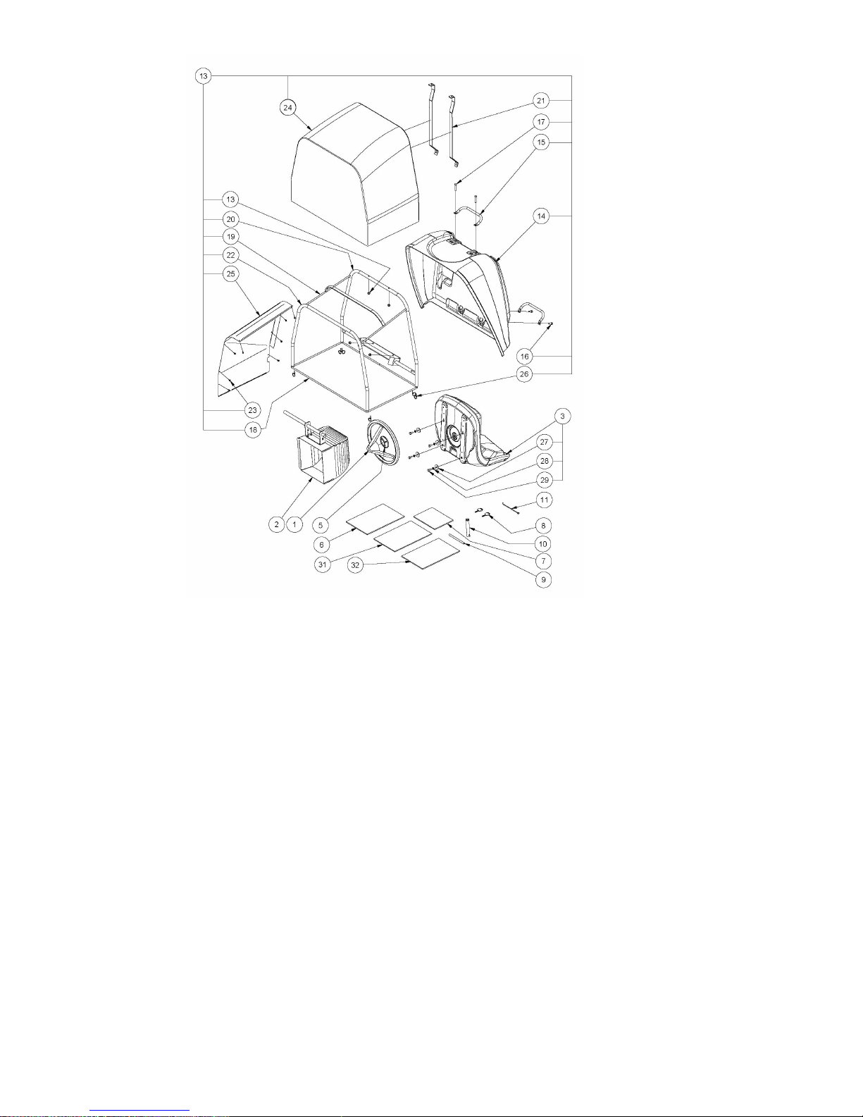
Loose Parts A12808L 16.5HP Rear Bagger
ITEM PART NUMBER DESCRIPTION QTY
1 SW13 Steering Wheel 1
2 A128060 Deflector, Discharge, Rear, 805(32") 1
3 A122110 Seat 1
4 95112 Cushion, Bottom, Seat, Medium, Red 1
5 Steering Wheel, Cover 1
6 Manual, Owner, Ride-On Mower, Stockman 3 1
7 Warranty Card-Reply Paid 1
8 90134 Key, Ignition Switch, Vinyl Covered, Steel 2
9 AM007 Bar, Tommy, 9.5x150, Znpl 1
10 AM295 Spanner, Tube, Spark Plug, 5/8"Af, Znpl 1
11 13127 Hook, Spring Pull 1
12 A129000 Sub-Assy, Catcher, Grass, Bag, Rear, 200l 1
13 NM8NT Nut, Hex, Nyloc, Thin, M 8, Pc6, Znpl 4
14 A102003 Cover, Catcher, Plastic, Red 1
15 14154 Handle, Front, Grass Catcher, Black 2
16 SH0825M Screw, Hex, M 8x 20, Pc8.8, Znpl 2
17 B0840M Bolt, Hex, M8x40, Pc8, Znpl 2
18 13312 Front, Catcher Frame, 150l 1
19 A129018 Frame, Rear, Black 1
20 A129005B Frame, Upper, 165l, Black 1
21 A129021B Bar, Tunnel, Top, Black 2
22 A129002B Frame, Lower, 165l, Black 1
23 ST0808D Screw, Hex Washer, Seal, Drill, #8-18x12, Gal 8
24 A129014 Bag, Catcher, Grass, Rear, 165l 1
25 A129061B Deflector, Inner, Side, Black 1
26 CABLETIES Cable Ties 100mm X 2.5 Black 6
27 W052003 Washer, Flat, Black, 5/16"X1-1/4"X3, Znpl 4
28 WS050216 Washer, Lock, Spring, 5/16"X1/8"X1/16", Znpl 4
29 SH0816M Screw, Hex, M 8x 16, Pc8.8, Znpl 4
30 PD006 Instruct, Pre-Delivery 1
31 Manual, Engine, Owner/Operator 1
Page 7
31 May 2013
Page 7
OWNERS MANUAL FOR MODELS A15713A & A15813A
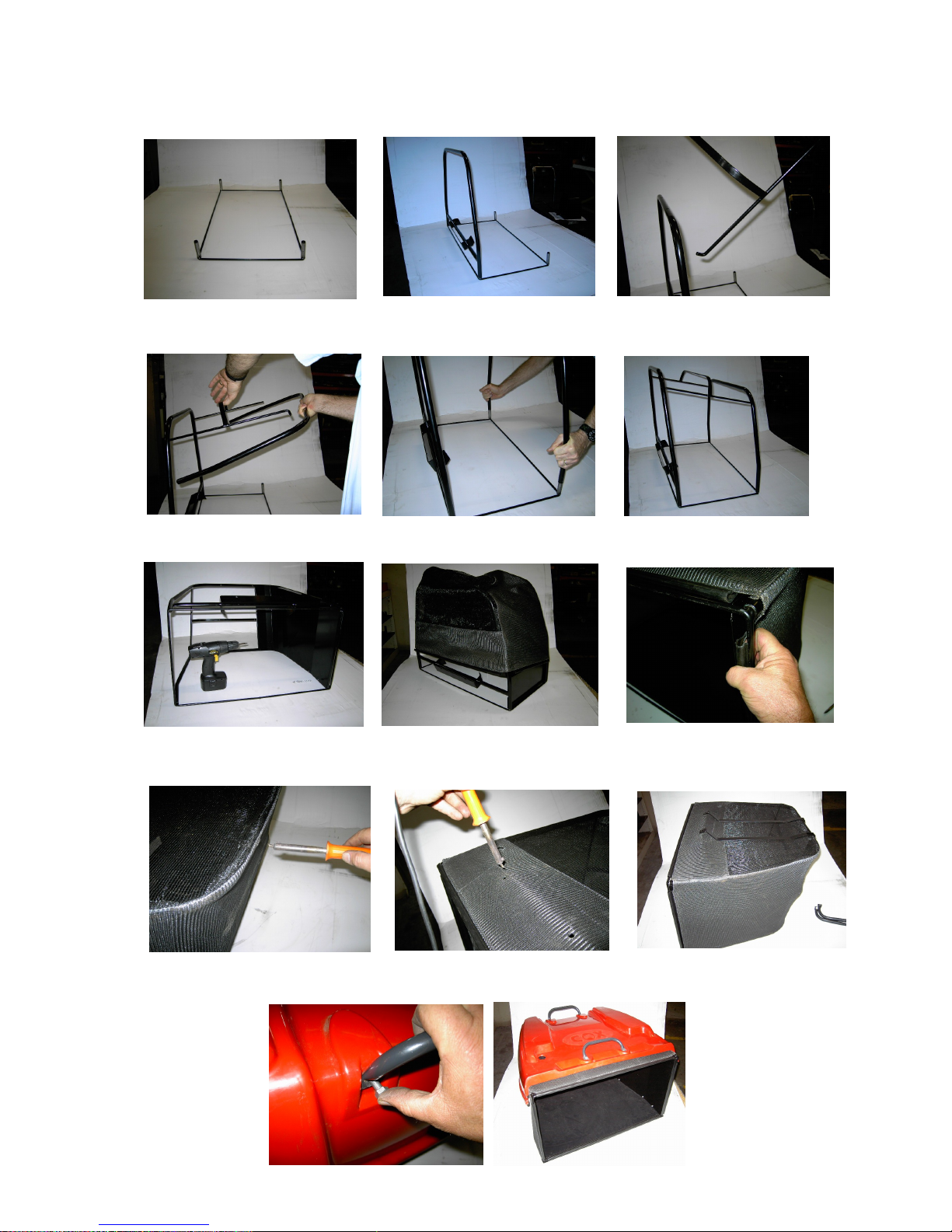
A12808L 16.5HP Rear Bagger Catcher Assembly
1/ Clean tubes with emery paper. Place the
front frame with the short tubes in each corner
on a flat surface with the short tubes up.
2/ Fit the upper frame over the outward
leaning front frame short tubes. Note: The
two holes in the upper frame near the
bent corners must face inwards.
3/ Install the rear frame by inserting hook
side of rear frame into upper frame, opposite
side to tilt lever mount bracket.
4/ Insert hook side into lower frame. 5/ Fit the lower frame over the two short tubes of the
front frame which lean inwards. Note: Make sure
the two holes in the sides of the lower frame
6/ Ensure tilt lever is angled toward front
frame before fitting M8x20 screws and nyloc
nuts.
8/ Feed the bag over the assembled frame
with the plain plastic base against the lower
frame (bottom of the catcher).
9/ Turn catcher over then clip the bag onto
the front frame.
10/ Using a small soldering iron melt
through the mesh at the four bolt holes in
the upper frame to suit the handle bolts.
11/ Fit braces as shown.
12/ Place the catcher
cover over the assembled bag and frame,
line up bolt holes.
Using the two M8x40
screws & nyloc nuts fit
one handle to the rear
of the catcher with the
handle holes facing
down and handle leaning toward the rear.
13/ Using the two M8x20 screws
and nyloc nuts fit the other handle
to the front of the catcher with the
handle holes fa cing forward.
Tighten all four handle screws.
14/ Use the cable ties in the top &
bottom corners if necessary to close
any gaps which may occur between
the bag and frame.
15/ Install catcher onto the machine and adjust the mounting
brackets so the top front edge of
the catcher bag makes contact with
the top lip of the mounting panel
when the catcher is closed.
Page 8

31 May 2013
Page 8
OWNERS MANUAL FOR MODELS A15713A & A15813A
IMPORTANT
RECOMMENDED FUEL
Unleaded fuel is recommended by all manufacturers of engines
fitted to Cox products.
DRIVE PRESSURE
Ensure when applying pressure to the drive pedal the wheels
start rotating, failure to adhere to this will result in clutch plate
and clutch cone damage.
SAFETY SWITCHES
Before operating machine, ensure that all safety switches are
operating correctly. Do not operate machine with faulty,
missing or damaged safety switches.
STARTING MACHINE
When starting machine, place right heel on foot switch located
on rear of footrest. Ensure that cutter is disengaged, otherwise
electric starter motor will not engage. If engine is cold move
engine speed control to choke start position and return to
desired engine speed setting when engine starts. Do not
attempt to operate engine with engine speed control lever in
choke position. (Note electric start engines fitted with recoil can
be manually started with cutter disengaged and ignition on).
BLADE WARNING
Do not use mowing attachment with broken or bent blades,
damaged or worn bolts and nuts or damaged cutter disc,
otherwise damage and premature wear will result from
vibration. Replace blades, bolts and nuts only in pairs to
maintain correct balance. Recommended blade nut torque is 36
-40Nm. Do not over tighten.
Keep both feet and hands clear
of the mowing attachment at all
times while attempting to start
or operate the machine.
WARNING
DO NOT OPERATE WITHOUT MOWING ATTACHMENT
DEFLECTOR FITTED & DOWN OR DO NOT OPERATE
WITHOUT GRASS CATCHER FITTED.
Safety footwear is recommended when operating machine.
Mount and dismount only from left hand side of machine.
Reference to left or right hand side of machine is determined by
sitting in the operating position on the machine.
Ensure machine has park brake engaged when attempting to
start engine.
Never allow engine revs to exceed more than 3600 RPM.
TO OPERATE
BEFORE STARTING/STOPPING:
See Engine Maintenance/Instruction Sheet. When stopping
engine, disengage cutter, return engine speed control to slow
position and switch off
DISENGAGING MOWING ATTACHMENT:
The cutter disengaging lever is situated on the right hand side
by the steering column. Before starting, disengage mowing
attachment by pulling lever fully back towards the operator.
For safety it is advisable at all times, other than when
mowing, that the mowing attachment be kept in the
disengaged position.
TO DRIVE FORWARD/REVERSE:
Engine speed is regulated by the engine speed control, set
engine speed control to desired engine power. Press down on
the forward section of the drive pedal for forward movement,
on the rear of the drive pedal for reverse. The amount of
pressure can be used to control the ground speed, especially in
heavier conditions. When operating the mower on slopes
greater than 10 degrees but less than 15 degrees for a
prolonged period, you may experience minor clutch fade,
should this occur, vary your mowing style eg: mow around
some flat areas, then the slope followed by the flat area again.
This will allow the drive to cool before travelling up the slope
again.
N.B. Ensure that when pressure is applied to the drive pedal
wheels are rotating or damage will occur to clutch plates.
MANOEUVRING:
Owing to the heel and toe type action of the drive pedal, it is
possible to take the machine straight from forward to reverse
and vice versa. This instant forward and reverse operation
makes the machine very manoeuvrable and the sharpest turns
can be negotiated easily and quickly.
TO BRAKE (WITH ENGINE RUNNING):
The drive pedal may be used to stop the machine. If travelling
forward push the pedal into reverse until machine stops, then
bring the pedal back to neutral position or vice versa if
travelling in reverse. Should a drive failure occur during
operation use the brake pedal situated on the left hand side
and forward of where your foot would rest during normal
operation.
TO BRAKE (WITH ENGINE STOPPED):
Use foot brake pedal only.
Damage to drive cone will occur if drive pedal is used to brake
the machine with the engine stopped.
PARKING AND TRANSPORTATION BRAKE:
Depress the lever protruding out of the left hand mudguard
downward and shift the lever to the left to engage the park
brake. Depress and shift to the right to release.
Do not engage parking brake unless the machine has
completely stopped.
Do not attempt to drive with park brake engaged damage will
occur to clutch plates and or large drive sprockets.
CUTTING HEIGHT ADJUSTMENT:
The height adjustment lever is located on the left hand side of
the machine and may be altered to suit varying conditions,
while the machine is in motion.
NOTE: When mowing slopes, keep drive pedal in forward or
reverse, depending on direction of travel. The low gearing will
prevent it from picking up excessive speed. If very steep it may
be necessary to slow engine speed slightly and /or, apply light
drive pedal pressure to the opposite drive direction. i.e. move
drive pedal into reverse when going forward down slope or into
forward when reversing down slope.
AVOID HOLDING MACHINE STATIONARY ON SLOPES
USING DRIVE PEDAL WITH ENGINE RUNNING AS
DAMAGE WILL OCCUR TO CLUTCH PLATES.
OPERATING INSTRUCTIONS
Page 9

31 May 2013
Page 9
OWNERS MANUAL FOR MODELS A15713A & A15813A
It is the owner’s responsibility to ensure that all-periodical
checks, necessary adjustments, services and repairs are
carried out.
STOP ENGINE - Never attempt any maintenance with the engine
running, remove spark plug lead and ensure the blades have
stopped rotating.
Before servicing, disconnect spark plug wire and ground it, disconnect
battery at negative terminal, to prevent accidental starting.
1. OIL CHANGING & FILTER REPLACEMENT (ENGINE): See Engine
Maintenance/Instructions Sheet and carry out as per Engine Manufacturers
Recommendations.
SERVICING ENGINE AIR CLEANER FOAM PRE-CLEANER— See
engine owners manual for correct method to check and service engine air
cleaner foam pre-cleaner.
2. LUBRICATION OF MACHINE: Lubrication of machine must be
carried out every 25 hours of operation or once a month, whichever occurs
first. More frequently when operated under adverse conditions.
A. OILING: A few drops of oil should be placed at the following
points: Steering linkage, disengaging linkages, height adjustment
mechanism, pivot bolt and linkages on clutch arm and clutch pedal.
B. CHAIN: Use only chain lube for lubrication of the drive and
steering chains.
C. GREASE POINTS: Grease nipples are located on top of the front
wheel stub axle.
Under no circumstances allow grease or oil to come into contact with
the Drive Cone or Clutch Plates. Should this problem occur, clean off
immediately with petrol whilst surface areas are cool and allow to dry
before operating machine.
3. TO CHECK BLADES: Stop engine. Remove spark plug lead. Side
Discharge Only, lift deflector and height adjustment control to highest
position. If necessary simply remove the blade bolt and nut using a
suitable spanner and replace worn parts.
4. ENGINE TO CLUTCH VEE BELT ADJUSTMENT: Loosen the four
engine mounting bolts. Move engine forward and adjust belt firmly.
Do not over tension belt. While maintaining tension on the engine
re-tighten bolts. Check belt tension at machine service period (25hrs)
or more frequently under heavy mowing conditions.
5. CLUTCH TO CUTTER VEE BELT ADJUSTMENT: Tension is
automatically adjusted by the belt tensioning springs.
6. CUTTER HEIGHT ADJUSTMENT: If the Mowing Attachment can
not be positioned to give a satisfactory grass cut height using the
available notches on the chassis the adjustable link can be used to
raise the Mowing Attachment to the desired height. Position the
mower on a smooth level surface and engage the mowing attachment,
lock the park brake on, and lower the Mowing Attachment to the
notch above the desired cut height. Place equal height spacers of the
desired height under the mowing attachment that can support the
mowing attachments weight and lower the Mowing Attachment onto
them. Loosen the 2 Screws located together on the front of the Rear
Link located below the front of the left foot rest. Push the Rear Link
rearwards until it stops and retighten the 2 screws. Adjust the rear
lifting link located on the middle rear of the mowing attachment by
tightening the nut until it just lifts the rear oif the mowing attachment
of the spacers. Lift the Mowing attachment off the spacers and
remove the spacers and check the cut height is as desired and the
deck is level to slightly higher (3—5 mm) at the back. Adjust height
again if required.
7. CUTTER BRAKE ADJUSTMENT: With disengagement handle in
engaged position and mowing attachment in low cut, normal clearance
between cutter head pulley and cutter head brake pad is
approximately 3mm (1/8"). To adjust clearance, remove 'R' pin from
brake pull rod, adjust to give required clearance, replace brake pull
rod and 'R' pin. Check operation after adjustment.
8. CLUTCH PLATE ADJUSTMENT: Periodically it will be found
necessary to adjust the clutch plates as the clutch cone wears. Carry
out this operation, with engine off and cutter in the engaged position.
Engage and disengage the cutter lever a few times and leave in the
engaged position, this will centre the clutch arm assembly into the neutral
position. Loosen the four square head set screws on the clutch plates
using tube spanner (AM006C1) and tommy bar (AM007). Insert the
clearance gauges supplied, one between the forward clutch plate and cone
and the other between the reverse clutch plate and cone and hook them
onto the intershaft. Slide both clutch plates against the clearance gauges
and clutch cone, tighten the set screws firmly onto the flat on the
intershaft. Remove gauges.
9. CUTTER DISENGAGING ADJUSTMENT: With the engine switched
off, engage the mowing attachment, then fully lower. Place a straight
edge vertically against the front of the front axle beam and in line with
the disengagement lever. Measure the distance between the straight
edge and the 8mm dia pin fitted with the small ‘R’ pin for the threaded
adjuster. Disengage mowing attachment and using the same method,
check the new distance. The difference should be 20 – 22mm. Engage
mowing attachment, remove ‘R’ pin and adjust threaded adjuster
accordingly. Install ‘R’ pin and re-check measurement. Due to normal
wear in clutch to cutter vee belt, the cutter disengagement lever will
move lower and touch the foot rest. When this occurs the amount of
travel will need to be re-adjusted. If a new vee belt is installed the
above settings will apply.
Start engine and raise cutter to full height stop, cutter belt should not
engage. If this occurs switch off engine, engage cutter then screw
adjuster out 1 – 2 turns then retest.
10. DRIVE CHAIN: Machines are fitted with automatic chain
adjusters. No adjustment is required. Replace chain when chain has
sagged enough to expose half the depth of the teeth on the bottom of
the large sprocket. Failure to replace worn chain will cause premature
wear of sprockets.
11. TO ADJUST STEERING CHAIN: Adjust chain by loosening the
four bolts which hold the steering idler shaft mounting brackets
(AM255) in position, slide forward to tension chain then retighten
bolts.
12. TO REMOVE MOWING ATTACHMENT: Fully lower mowing
attachment and engage, remove weight compensating spring, remove
'R' pin from rear lifting link and disconnect, remove ‘R’ pin from cutter
brake adjusting rod and disconnect, disengage mowing attachment,
remove belt, remove front pivot pin, Turn steering wheel to the left to
slide out mowing attachment. To refit, reverse the above.
13. TYRE PRESSURE: 140 Kpa (20.P.S.I.) approximately front and
rear. Uneven pressure can give an uneven finish when mowing and
may cause damage to tyres and/or tubes.
14. BATTERY MAINTENANCE: When not in use, a battery
discharges by as much as 1% a day, more when the climate is warm.
To make up for this loss, a boosting charge should be given once a
month. Disconnect battery terminals to charge, then allow to stand
minimum 1/2hr before re-connecting (re-check electrolyte level). If a
battery is not used for a period of more than three (3) months, the
terminals should be disconnected and trickle charged at two (2) amps
for two (2) hours once every three (3) months or before use.
15. SEAT ADJUSTMENT: Loosen four seat mounting bolts and slide
seat into desired position in slots and re-tighten bolts.
16. REPLACE DRIVE CHAIN: Engage park brake, jack up rear of
machine, and remove L/H wheel. Push chain tensioner arms, one at a
time, away from chain and using a suitable spanner tighten pivot bolt
lock nuts to hold them out. Release park brake then turn rear axle to
bring chain into a suitable position for removal of the chain connecting
link. Remove connecting link and chain. Inspect both sprockets for
wear or damage, replace if necessary. Install new chain and
connecting link with the link clip between the wheel and chain.
Release pivot arm nuts until arm moves freely back to chain. Engage
park brake, install wheel and lower machine.
17. CLEANING AND POLISHING POLYETHYLENE BONNET AND
REAR MUDGUARD: To keep scratches on bonnet and mudguard to
minimum, do not rub or brush off with bare hands, use a soft cloth or
a light flow of compressed air. For dirt, wash with a steady stream of
water only (no detergent), then blow off excess water with air. To
polish remove excess dust or dirt. When surface is dry, spray on an
automotive type plastic preservative and leave on for 30 to 60
seconds. Using a dry soft cloth (i.e. cheesecloth) wipe off to bring up
lustre.
GENUINE SPARE PARTS: Always use Genuine Cox Factory Made
Spare Parts. Use of non-genuine COX spares will void your warranty.
SAFETY FIRST: The use of any mechanical device can cause injury if
incorrect procedures are used. Please ensure that all family members
of intended operators read safety section of this manual thoroughly.
TORQUE SETTINGS
1/4” UNC BOLT/NUT 10Nm (84lbf in)
5/16” UNC BOLT/NUT 20Nm (180lbf in)
3/8” UNC BOLT/NUT 36Nm (27lbf ft)
7/16” UNF BOLT 68Nm (50lbf ft)
6mm BOLT/NUT 9Nm (80lbf in)
20mm NUT 100Nm (74lbf ft)
5/8” UNF NUT 100Nm (74lbf ft)
MAINTENANCE INSTRUCTIONS
Page 10

31 May 2013
Page 10
OWNERS MANUAL FOR MODELS A15713A & A15813A
BEFORE STORAGE
BEFORE STORAGE
BEFORE STORAGE
DATE / / HOURS..........................DEALER................................................
MAINTENANCE SCHEDULE
BEFORE EACH USE
BEFORE EACH USE
BEFORE EACH USE
Check engine oil level, adjust if required
Check engine air cleaner foam pre-cleaner, service if required
Check engine rotating screen/finger guard, clean if required
Check operation of safety switches, service if required
Check foot brake operation, adjust if required.
Check tyre pressures, adjust if required
Check for loose fasteners, tighten if required
Lubricate stub axles
Check mowing attachment cutter blades, bolts, nuts, disc/s,
housing, and guards for wear or damage, replace if required
Change engine oil - Clean machine - Lubricate as per required
EVERY 5 HOURS
EVERY 5 HOURS
EVERY 5 HOURS
Check engine oil level, adjust if required
Check engine air cleaner foam pre-cleaner, service if req.
Check engine rotating screen/finger guard, clean if required
Check operation of safety switches, service if required
Check foot brake operation, adjust if required.
Check tyre pressures, adjust if required
Check for loose fasteners, tighten if required
Lubricate stub axles
Check mowing attachment cutter blades, bolts, nuts, disc/s, housing,
and guards for wear or damage, replace if required
1 MONTH OR 5 HOURS W
1 MONTH OR 5 HOURS W
1 MONTH OR 5 HOURS W
HICH EVER OCCURS FIRST
HICH EVER OCCURS FIRST
HICH EVER OCCURS FIRST
Change engine oil
Check engine air cleaner foam pre-cleaner , service if required
Check engine rotating screen/finger guard, clean if required
Check foot brake operation, adjust if required
Check operation of safety switches, service if required
Check tyre pressures, adjust if required
Lubricate stub axles
Check mowing attachment cutter blades, bolts, nuts, disc/s, housing ,
and guards for damage, replace if required
Check clutch arm action, adjust if required
Check and adjust engine to clutch vee belt if required..
Check for loose fasteners, tighten if required
Check clutch to cutter vee belt and adjust cutter housing level if required
DATE / / HOURS.......................CUSTOMER................................................
3 MONTH OR 25 HOURS
3 MONTH OR 25 HOURS
3 MONTH OR 25 HOURS
WHICH EVER OCCURS FIRST
WHICH EVER OCCURS FIRST
WHICH EVER OCCURS FIRST
Change engine oil if operating under heavy load or high ambient temperature Check engine air cleaner foam pre-cleaner, service if required *
Check engine rotating screen/finger guard, clean if required *
Check foot brake operation, adjust if required
Check operation of safety switches and replace if required
Check tyre pressures, adjust if required
Lubricate stub axles
Check mowing attachment cutter blades, bolts, nuts, disc/s, housing ,
and guards for wear or damage, replace if required
Check and adjust engine to clutch vee belt if required..
Check battery condition, service if required
Check clutch to cutter vee belt and adjust cutter housing level if required
Check for loose fasteners, tighten if required
*Service more often under dusty conditions, or where air borne debris is present
*Service more often under dusty conditions, or where air borne debris is present
DATE / / HOURS..........................DEALER................................................
Change engine oil if operating under heavy load or high ambient temperature
Check engine air cleaner foam pre-cleaner, service if required *
Check engine rotating screen/finger guard, clean if required *
Check foot brake operation, adjust if required
Check operation of safety switches and replace if required
Check tyre pressures, adjust if required
Lubricate stub axles
Check mowing attachment cutter blades, bolts, nuts, disc/s, housing ,and guards for wear or damage, replace if required
Check for loose fasteners, tighten if required
Check and adjust engine to clutch vee belt if required..
Check battery condition, service if required
Check clutch to cutter vee belt and adjust cutter housing level if required
6 MONTH OR 50 HOURS
6 MONTH OR 50 HOURS
6 MONTH OR 50 HOURS
WHICH EVER OCCURS FIRST
WHICH EVER OCCURS FIRST
WHICH EVER OCCURS FIRST
Page 11

31 May 2013
Page 11
OWNERS MANUAL FOR MODELS A15713A & A15813A
*Service more often under dusty conditions, or where air borne debris is present
15 MONTHS OR 125 HOURS WHICH EVER OCCURS FIRST
15 MONTHS OR 125 HOURS WHICH EVER OCCURS FIRST
15 MONTHS OR 125 HOURS WHICH EVER OCCURS FIRST
9 MONTHS OR 75 HOURS WHICH EVER OCCURS F
9 MONTHS OR 75 HOURS WHICH EVER OCCURS F
9 MONTHS OR 75 HOURS WHICH EVER OCCURS F
IRST
IRST
IRST
Change engine oil if operating under heavy load or high ambient
temperature
Check engine air cleaner foam pre-cleaner, service if required *
Check engine rotating screen/finger guard, clean if required *
Check foot brake operation, adjust if required
Check operation of safety switches and replace if required
Check tyre pressures, adjust if required
Lubricate stub axles
Check mowing attachment cutter blades, bolts, nuts, disc/s, housing ,
and guards for wear or damage, replace if required
Check for loose fasteners, tighten if required
Check battery condition, service if required
Check clutch to cutter vee belt and adjust cutter housing level if required
Check and adjust engine to clutch vee belt if required..
12 MONTHS OR 100 HOURS WHICH EVER OCCURS FIRST
12 MONTHS OR 100 HOURS WHICH EVER OCCURS FIRST
12 MONTHS OR 100 HOURS WHICH EVER OCCURS FIRST
*Service more often under dusty conditions, or where air borne debris is present
DATE / / HOURS...............CUSTOMER/DEALER................................................
DATE / / HOURS..........................DEALER................................................
*Service more often under dusty conditions, or where air borne debris is present
DATE / / HOURS................CUSTOMER/DEALER................................................
18 MONTHS OR 150 HOURS WHICH EVER OCCURS FIRST
18 MONTHS OR 150 HOURS WHICH EVER OCCURS FIRST
18 MONTHS OR 150 HOURS WHICH EVER OCCURS FIRST
*Service more often under dusty conditions, or where air borne debris is present
DATE / / HOURS..........................DEALER................................................
Change engine oil filter
Change engine oil
Check engine spark plug, clean, adjust, or replace if required
If fitted clean engine exhaust spark arrester
Check engine air cleaner foam pre-cleaner , service if required *
Check engine air cleaner cartridge, service if required*
Clean engine cooling system*
Check clutch arm action, adjust if required
Replace in-line fuel filter
Check foot brake operation and lining for ware, adjust or replace if req
Lubricate stub axles
Check for loose fasteners, tighten if required
Check operation of safety switches, service if required
Check tyre pressures, adjust if required
Check drive chain and sprockets for wear, replace if required
Check steering chain an sprockets or wear, adjust if required
Check mowing attachment cutter blades, bolts, nuts, disc/s, housing,
and guards for wear or damage, replace if required
Check clutch arm action, adjust if required
Re-tension rear wheel retaining nut/s
Check battery condition, service if required
Check drive clutch plates and cone for wear or damage, adjust or
service if required
Check belts for wear or damage, replace if required
Check and adjust engine to clutch vee belt if required..
Check clutch to cutter vee belt and adjust cutter housing level if
required
Change engine oil if operating under heavy load or high ambient temperature
Check engine air cleaner foam pre-cleaner, service if required *
Check engine rotating screen/finger guard, clean if required *
Check operation of safety switches and replace if required
Check foot brake operation, adjust if required
Lubricate stub axles
Check tyre pressures, adjust if required
Check battery condition, service if required
Check mowing attachment cutter blades, bolts, nuts, disc/s, housing,
and guards for wear or damage, replace if required
Check for loose fasteners, tighten if required
Check clutch to cutter vee belt and adjust cutter housing level if required
Check and adjust engine to clutch vee belt if required..
Change engine oil
If fitted clean engine exhaust spark arrestor
Check engine air cleaner foam pre-cleaner , service if required *
Check engine rotating screen/finger guard , clean if required *
Check foot brake operation and lining for ware, adjust or replace if
required
Check operation of safety switches, service if required
Check tyre pressures, adjust if required
Lubricate stub axles
Check steering chain an sprockets or wear, adjust if required
Check mowing attachment cutter blades, bolts, nuts, disc/s, housing,
and guards for wear or damage, replace if required
Check belts for wear or damage, replace if required
Check drive chain and sprockets for wear, replace if required
If fitted check mowing attachment brake pad for wear, replace if required
Check drive clutch plates and cone for wear or damage,
adjust or service if required
Check clutch arm action, adjust if required
Check battery condition, service if required
Check for loose fasteners, tighten if required
Check and adjust engine to clutch vee belt if required..
Check clutch to cutter vee belt and adjust cutter housing level if required
Page 12

31 May 2013
Page 12
OWNERS MANUAL FOR MODELS A15713A & A15813A
21 MONTHS OR 175 HOURS WHICH EVER OCCURS FIRST
21 MONTHS OR 175 HOURS WHICH EVER OCCURS FIRST
21 MONTHS OR 175 HOURS WHICH EVER OCCURS FIRST
Change engine oil if operating under heavy load or high ambient
temperature
Check engine air cleaner foam pre-cleaner, service if required *
Check engine rotating screen/finger guard, clean if required *
Check foot brake operation, adjust if required
Check operation of safety switches and replace if required
Check tyre pressures, adjust if required
Lubricate stub axles
Check mowing attachment cutter blades, bolts, nuts, disc/s, housing ,
and guards for wear or damage, replace if required
Check battery condition, service if required
Check for loose fasteners, tighten if required
Check clutch to cutter vee belt and adjust cutter housing level if required
Check and adjust engine to clutch vee belt if required..
24 MONTHS OR 200 HOURS WHICH EVER OCCURS FIRST
24 MONTHS OR 200 HOURS WHICH EVER OCCURS FIRST
24 MONTHS OR 200 HOURS WHICH EVER OCCURS FIRST
*Service more often under dusty conditions, or where air borne debris is present
DATE / / HOURS...............CUSTOMER/DEALER................................................
Replace engine oil filter
Change engine oil
Check engine spark plug, clean, adjust, or replace if required
If fitted clean engine exhaust spark arrestor
Check engine air cleaner foam pre-cleaner , service if required *
Check engine air cleaner cartridge, service if required
Clean engine cooling system*
Check foot brake operation and lining for ware, adjust or replace if
required
Check operation of safety switches, service if required
Check tyre pressures, adjust if required
Lubricate stub axles
Check steering chain an sprockets or wear, adjust if required
Check mowing attachment cutter blades, bolts, nuts, disc/s, housing,
and guards for wear or damage, replace if required
Check belts for wear or damage, replace if required
Check drive chain and sprockets for wear, replace if required
Check drive clutch plates and cone for wear or damage,
adjust or service if required
Check clutch arm action, adjust if required
Check battery condition, service if required
Check for loose fasteners, tighten if required
Check and adjust engine to clutch vee belt if required..
Check clutch to cutter vee belt and adjust cutter housing level if required
*Service more often under dusty conditions, or where air borne debris is present
DATE / / HOURS..........................DEALER................................................
27 MONTHS OR 225 HOURS WHICH EVER OCCURS FIRST
27 MONTHS OR 225 HOURS WHICH EVER OCCURS FIRST
27 MONTHS OR 225 HOURS WHICH EVER OCCURS FIRST
Change engine oil if operating under heavy load or high ambient temperature
Check engine air cleaner foam pre-cleaner, service if required *
Check engine rotating screen/finger guard, clean if required *
Check foot brake operation, adjust if required
Check operation of safety switches and replace if required
Check tyre pressures, adjust if required
Lubricate stub axles
Check mowing attachment cutter blades, bolts, nuts, disc/s, housing ,
and guards for wear or damage, replace if required
Check battery condition, service if required
Check for loose fasteners, tighten if required
Check clutch to cutter vee belt and adjust cutter housing level if required
Check and adjust engine to clutch vee belt if required..
*Service more often under dusty conditions, or where air borne debris is present
DATE / / HOURS................CUSTOMER/DEALER................................................
30 MONTHS OR 250 HOURS WHICH EVER OCCURS FIRST
30 MONTHS OR 250 HOURS WHICH EVER OCCURS FIRST
30 MONTHS OR 250 HOURS WHICH EVER OCCURS FIRST
Change engine oil
If fitted clean engine exhaust spark arrestor
Check engine air cleaner foam pre-cleaner , service if required *
Check engine rotating screen/finger guard , clean if required *
Check foot brake operation and lining for ware, adjust or replace if
required
Check operation of safety switches, service if required
Check tyre pressures, adjust if required
Lubricate stub axles
Check steering chain an sprockets or wear, adjust if required
Check mowing attachment cutter blades, bolts, nuts, disc/s, housing, and guards for wear or damage, replace if required
Check belts for wear or damage, replace if required
Check drive chain and sprockets for wear, replace if required
Check drive clutch plates and cone for wear or damage,
adjust or service if required
Check clutch arm action, adjust if required
Check battery condition, service if required
Check for loose fasteners, tighten if required
Check and adjust engine to clutch vee belt if required..
Check clutch to cutter vee belt and adjust cutter housing level if
required
*Service more often under dusty conditions, or where air borne debris is present
DATE / / HOURS..........................DEALER................................................
Page 13

31 May 2013
Page 13
OWNERS MANUAL FOR MODELS A15713A & A15813A
33 MONTHS OR 275 HOURS WHICH EVER OCCURS FIRST
33 MONTHS OR 275 HOURS WHICH EVER OCCURS FIRST
33 MONTHS OR 275 HOURS WHICH EVER OCCURS FIRST
Change engine oil if operating under heavy load or high ambient
temperature
Check engine air cleaner foam pre-cleaner, service if required *
Check engine rotating screen/finger guard, clean if required *
Check foot brake operation, adjust if required
Check operation of safety switches and replace if required
Check tyre pressures, adjust if required
Lubricate stub axles
Check mowing attachment cutter blades, bolts, nuts, disc/s, housing , and guards for wear or damage, replace if required
Check battery condition, service if required
Check for loose fasteners, tighten if required
Check clutch to cutter vee belt and adjust cutter housing level if
required
Check and adjust engine to clutch vee belt if required..
*Service more often under dusty conditions, or where air borne debris is present
DATE / / HOURS.................CUSTOMER/DEALER................................................
36 MONTHS OR 300 HOURS WHICH EVER OCCURS FIRST
36 MONTHS OR 300 HOURS WHICH EVER OCCURS FIRST
36 MONTHS OR 300 HOURS WHICH EVER OCCURS FIRST
Replace engine oil filter
Change engine oil
Check engine spark plug, clean, adjust, or replace if required
If fitted clean engine exhaust spark arrestor
Check engine air cleaner foam pre-cleaner , service if required *
Check engine air cleaner cartridge, service if required
Clean engine cooling system*
Check foot brake operation and lining for ware, adjust or replace if
required
Check operation of safety switches, service if required
Check tyre pressures, adjust if required
Lubricate stub axles
Check steering chain an sprockets or wear, adjust if required
Check mowing attachment cutter blades, bolts, nuts, disc/s, housing, and guards for wear or damage, replace if required
Check belts for wear or damage, replace if required
Check drive chain and sprockets for wear, replace if required
Check drive clutch plates and cone for wear or damage,
adjust or service if required
Check clutch arm action, adjust if required
Check battery condition, service if required
Check for loose fasteners, tighten if required
Check and adjust engine to clutch vee belt if required..
Check clutch to cutter vee belt and adjust cutter housing level if
required
*Service more often under dusty conditions, or where air borne debris is present
DATE / / HOURS..........................DEALER................................................
We are proud that you have purchased a Cox product and urge you to follow these instructions
to obtain the maximum life for your machine. If in doubt check with your supplier.
Page 14

31 May 2013
Page 14
OWNERS MANUAL FOR MODELS A15713A & A15813A
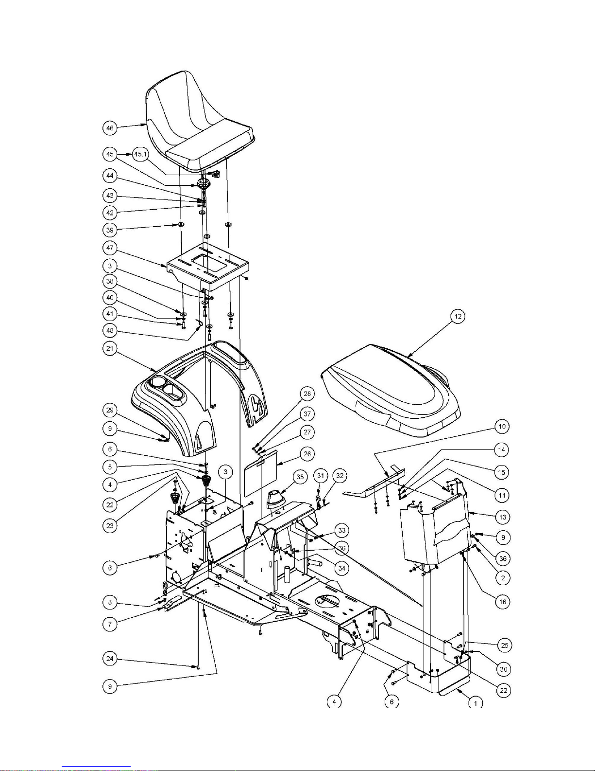
Body Components 16.5HP, 19.5HP B&S
for serial nos from C1632BS S/N 5981, C1638BS S/N 3016, C1932BS S/N 2026,
C1938BS S/N 1111
Page 15

31 May 2013
Page 15
OWNERS MANUAL FOR MODELS A15713A & A15813A
ITEM PART NUMBER DESCRIPTION QTY
1 NM6NT Nut 10
2 NM8NT Nut 7
3 SH0820M Screw 6
4 SH0620M Screw 3
5 SPM6X16 Screw, Pan 1
6 13096 Depressor, Foot Switch 1
7 95044 Mudguard 1
8 W06MN Washer 3
9 SPPK6X20 Screw, Pan 2
14 W040818 Washer 2
15 WS040816 Washer, Lock, Spring 3
16 SH0616M Screw 5
17 NCM6x2.6x9.5 Nut, Cage 2
19 A131021R Door, Console 1
20 13060 Spring, Seat 2
21 W05M202 Washer 2
22 A107014R08L Stand, Tank, Fuel 1
23 96114 Strap, Bonnet 2
24 PR04M4.8 Rivet 2
25 NCM5X2.5X9.5 Nut, Cage 2
26 NCM6X1.6X9.5 Nut, Cage 1
27 SPPK5X16 Screw, Pan 7
28 95043 Cowl, Bonnet 1
29 WSR12 Washer, Seal, Epdm Rubber 7
30 W030820 Washer 7
31 A145073R Nose, Bonnet 13HP Honda 1
A143073R11M Nose, Bonnet B&S Only 1
32 A131009 Cover, Shaft, Steering 1
33 SPPK5X16 Screw, Pan 2
34 W041216 Washer 6
35 A140075B Baffle, Hot Air, Bonnet, B&S, 19.5 Hp Only 1
36 SPM6X12 Screw, Pan 19.5 Hp Only 2
37 NM6NT Nut 2
38 W0620HD Washer 4
39 13247 Washer 4
40 WS06081.5 Washer, Lock, Spring 4
41 B0620C Bolt 4
42 BHSSC0410 Screw, Button, Hex Soc 2
43 WS040816 Washer, Lock, Spring 2
44 W040818 Washer 2
45 AM16512F Switch, Seat 1
45.1 SP1PNCSM Switch, Plunger, 1 Pole, Nc, Snap Mtg 1
46 A140110 Seat 1
47 A143009R Mount, Seat 1
48 CABLETIES Cable Ties 1
Body Components 16.5HP, 19.5HP B&S
for serial nos from C1632BS S/N 5981, C1638BS S/N 3016, C1932BS S/N 2026,
C1938BS S/N 1111
Page 16
31 May 2013
Page 16
OWNERS MANUAL FOR MODELS A15713A & A15813A
Body Components 16HP Honda Only for serial nos from C1632HS S/N 8183,
C1638HT S/N 6580
Page 17

31 May 2013
Page 17
OWNERS MANUAL FOR MODELS A15713A & A15813A
Body Components 16HP Honda Only for serial nos from C1632HS S/N 8183,
C1638HT S/N 6580
ITEM PART NUMBER DESCRIPTION QTY
1 A145040R Bumper, Front 1
2 SH0816M Screw 2
3 NM8NT Nut 8
4 13060 Spring, Seat 2
5 W05M202 Washer 2
6 SH0820M Screw 2
7 13096 Depressor, Foot Switch 1
8 SPM6X16 Screw, Pan 1
9 NM6NT Nut 5
10 A119075B Baffle, Hot Air, Bonnet, Front 1
11 SPPK5X16 Screw, Pan 7
12 95043 Cowl, Bonnet 1
13 A123073R10G Nose, Bonnet, Sloping 1
14 WSR12 Washer, Seal, Epdm Rubber 7
15 W030820 Washer 7
16 W051216 Washer 2
21 95044 Mudguard 1
22 SH0620M Screw 4
23 W06MN Washer 2
24 SPPK6X20 Screw, Pan 2
25 NHCM8 Nut, Hex, Conelok 2
26 A131021R Door, Console 1
27 W040816 Washer 1
28 SH0616M Screw 1
29 W041216 Washer 4
30 NHM6 Nut 2
31 96114 Strap, Bonnet 2
32 PR04M4.8 Rivet 2
33 NCM5X2.5X9.5 Nut, Cage 2
34 NCM6X1.6X9.5 Nut, Cage 1
35 A131009 Cover, Shaft, Steering 1
36 SPPK5X16 Screw, Pan 2
37 WS040816 Washer, Lock, Spring 1
38 W0620HD Washer 4
39 13247 Washer 4
40 WS06081.5 Washer, Lock, Spring 4
41 B0620C Bolt 4
42 BHSSC0410 Screw, Button, Hex Soc 2
43 WS040816 Washer, Lock, Spring 2
44 W040818 Washer 2
45 AM16512F Switch, Seat 1
45.1 SP1PNCSM Switch, Plunger, 1 Pole, Nc, Snap Mtg 1
46 A140110 Seat 1
47 A143009R Mount, Seat 1
48 CABLETIES Cable Ties 1
Page 18

31 May 2013
Page 18
OWNERS MANUAL FOR MODELS A15713A & A15813A
Body Components Rear Discharge Only for serial numbers from C1632BRBS s/n9271
Page 19

31 May 2013
Page 19
OWNERS MANUAL FOR MODELS A15713A & A15813A
Body Components Rear Discharge Only for serial numbers from C1632BRBS s/n9271
ITEM PART NUMBER DESCRIPTION QTY
1 13060 Spring, Seat 2
2 13096 Depressor, Foot Switch 1
3 95044 Mudguard 1
4 A102128 Seal, Mudguard, Catcher Cover 1
7 A125203R Extension, Towbar 1
8 A128020 Sub-Assy, Wall, Catcher 1
9 NCM6X1.6X9.5 Nut, Cage 2
10 A128051R Infill, Mudguard-Catcher 1
11 A129035B Bracket, Catcher, Left 1
12 A129037B Bracket, Catcher, Right 1
13 A131009 Cover, Shaft, Steering 1
14 A131021R Door, Console 1
15 SPPK5X16 Screw, Pan 7
16 95043 Cowl, Bonnet 1
17 WSR12 Washer, Seal, Epdm Rubber 7
18 W030820 Washer 7
19 A143073R11M Nose, Bonnet 1
20 96114 Strap, Bonnet 2
21 PR04M4.8 Rivet 2
22 A144031B Bracket, Chassis, Left 1
23 A144033B Bracket, Chassis, Right 1
24 NM12NT Nut 3
25 NM6NT Nut 3
26 NM8NT Nut 10
27 SH0616M Screw 3
28 SH0620M Screw 2
30 SH0820M Screw 8
31 SH0825M Screw 4
32 SH1235M Screw 3
33 SPM6X16 Screw, Pan 1
34 SPPK5X16 Screw, Pan 2
35 SPPK6X20 Screw, Pan 2
36 W040818 Washer 1
37 W041216 Washer 2
39 W05M202 Washer 2
40 W06MN Washer 2
41 WS040816 Washer, Lock, Spring 1
42 WS050216 Washer, Lock, Spring 4
43 W0620HD Washer 4
44 13247 Washer 4
45 WS06081.5 Washer, Lock, Spring 4
46 B0620C Bolt 4
47 BHSSC0410 Screw, Button, Hex Soc 2
48 WS040816 Washer, Lock, Spring 2
49 W040818 Washer 2
50 AM16512F Switch, Seat 1
50.1 SP1PNCSM Switch, Plunger, 1 Pole, Nc, Snap Mtg 1
51 A140110 Seat 1
52 A143009R Mount, Seat 1
53 CABLETIES Cable Ties 1
Page 20

31 May 2013
Page 20
OWNERS MANUAL FOR MODELS A15713A & A15813A
Engine Ancillary Components B&S Engines ONLY
Page 21

31 May 2013
Page 21
OWNERS MANUAL FOR MODELS A15713A & A15813A
Engine Ancillary Components B&S Engines ONLY
ITEM PART NUMBER DESCRIPTION QTY
1 A131101 Assy, Control, Throttle 1
2 Sub-Assy, Tank 1
2.1 CF01 Cap, Fuel 1
2.2 AM294 Grommet, Fuel Tap 1
2.3 AM293 Petrol Tap 1
2.4 14107 Line, Fuel 1
2.5.1 80033 Tank, Fuel 1
2.5.2 DEC08505K Decal, Warning, Fuel 1
3 A131007B Bracket, Restrain, Fuel Tank, Black 1
4 80037 Grommet 1
5 A108101 Pulley, Engine 1
6 A108103 Spacer, Pulley, Engine 1
7 A108104 Key 1
8 A108109B09H Plate, Base, Engine 1
9 AM078B0 Engine Mount Bolt Plate 2
10 B0524C Bolt, Hex 4
11 GS0505C Screw, Set 1
12 NM5NT Nut, Hex 2
13 BHSSM5X12 Screw, Control, Throttle 2
NM5NT Nut, Control, Throttle 2
14 SH0724F Bolt, Hex 1
15 SPM5X12 Screw, Pan 2
16 W030820 Washer, Flat 2
17 W051218 Washer, Flat 4
18 W071416 Washer, Flat 2
19 W072004 Washer, Flat 1
20 WS050216 Washer, Lock, Spring 4
21 WS071008 Washer, Lock, Spring 1
AM295 Spark Plug Spanner 1
Page 22

31 May 2013
Page 22
OWNERS MANUAL FOR MODELS A15713A & A15813A
Engine Ancillary Components 16HP Honda
Page 23

31 May 2013
Page 23
OWNERS MANUAL FOR MODELS A15713A & A15813A
Engine Ancillary Components 16HP Honda
ITEM PART NUMBER DESCRIPTION QTY
1 A133133 Control, Speed, Engine 1
A119135 Clamp, Cable 1
NM8NT Nut 1
SH0616M Screw 1
W041216 Washer 1
2 80025 Deflector, Exhaust Gas 1
3 80037 Grommet 1
4 90167 Muffler, Exhaust 1
5 90168 Clamp, Hose, T-Bolt 4
6 A131007B Bracket, Restrain, Fuel Tank 1
7 A108101 Pulley, Engine 1
8 A108103 Spacer, Pulley, Engine 1
9 A108104 Key 1
10 A116207Z Plate, Mounting, Engine, Left 1
11 A116208Z Plate, Mounting, Engine, Right 1
12 A119121C Pipe, Exhaust, Hon 1
13 A119123C Pipe, Exhaust, Hon 1
14 A119125Z Bracket, Muffler 1
15 A119127B09G Baffle, Hot Air, Engine, Front 1
16 A119129 Fuel Line, 240l 1
17 AM293 Petrol Tap 1
18 AM294 Grommet 1
19 B0408TFS Screw 4
20 CF01 Cap, Fuel 1
21 GS0505C Screw, Set 1
22 Kit, Tank, Fuel 1
22.1 80033 Tank, Fuel 1
22.2 DEC08505K Decal, Warning, Fuel 1
23 NCM5X2.5X9.5 Nut, Cage 2
24 NFM6 Nut, Hex, Flange 2
25 NHCM8 Nut, Hex, Conelok 4
26 BHSSM5X12 Bolt 2
NM5NT Nut 2
27 SH0724F Bolt 1
28 SH0850M Screw 4
29 SPM5X12 Screw, Pan 2
30 W071416 Washer, Flat 2
31 W072004 Washer, Flat 1
32 WS050216 Washer, Lock, Spring 4
33 WS071008 Washer, Lock, Spring 1
AM005G0 Spark Plug Spanner 1
Page 24

31 May 2013
Page 24
OWNERS MANUAL FOR MODELS A15713A & A15813A
Page 25

31 May 2013
Page 25
OWNERS MANUAL FOR MODELS A15713A & A15813A
16.5HP, 19.5HP B&S Electrical Components Schematic
ITEM PART NUMBER DESCRIPTION QTY
Engine, B&S 1
1 AM16512F Switch, Seat 1
1.1 SP1PNCSM Switch, Plunger 1
2 SKIT132 Switch, Plunger , Inc Cover 1
3 Battery, Automotive, 12V, CMFU1, 9PL, 240CCA 1
4 13125 Switch, Key 1
5 AM015 Pair, Key, Ignition 1
6 SH0616M Screw 2
7 AM159 Solenoid, Starter 1
NM6NT Nut 2
SH0620M Screw 2
8 SKIT133 Switch, Plunger, Inc Cover 1
9 NHM6 Nut 2
10 A143026 Harness, Wiring, Main 1
11 89082 Lead, Battery, Red, L= 295 1
12 AM265 Lead, Battery, Red, L= 490 1
13 15235 Lead, Battery, Black, 3term 1
14 N04C Nut 2
15 W040818 Washer 2
16 A143112 Harness, Wiring, Engine, B&S 1
17 Fuse, Glass, 3ag, 15 Amp 1
18 AM211 Hour Meter, Optional
Page 26

31 May 2013
Page 26
OWNERS MANUAL FOR MODELS A15713A & A15813A
Page 27

31 May 2013
Page 27
OWNERS MANUAL FOR MODELS A15713A & A15813A
16HP Honda Only Electrical Components Schematic
ITEM PART NUMBER DESCRIPTION QTY
Engine, 16.0hp, V2cyl, Elec, Hon, GXV530
1 AM16512F Switch, Seat 1
1.1 SP1PNCSM Switch, Plunger 1
2 A143026 Harness, Wiring, Main 1
3 13369 Lead, Battery, Black, 3term 1
4 13125 Switch, Key 1
5 Battery, Automotive, 12V, CMFU1, 9PL, 240CCA 1
6 Regulator/Rectifier, Honda 1
7 SKIT132 Switch, Plunger, Inc Cover 1
8 SKIT133 Switch, Plunger, Inc Cover 1
9 A143113 Harness, Wiring, Engine, Hon, 16.0 Hp 1
10 AM015 Pair, Key, Ignition 1
14 84132 Lead, Battery, Red 1
16 Fuse, Glass, 3 Ag, 15 Amp 1
17 NHM8 Nut 2
18 B0635M Bolt 2
19 NHM6 Nut 2
NM6NT Nut 2
20 SH0616M Screw 2
21 AM211 Hour Meter, Optional
Page 28

31 May 2013
Page 28
OWNERS MANUAL FOR MODELS A15713A & A15813A
Steering Components
Page 29

31 May 2013
Page 29
OWNERS MANUAL FOR MODELS A15713A & A15813A
Steering Components
ITEM PART NUMBER DESCRIPTION QTY
1 A142103R Beam, Axle, Front, Red 1
2 13242 Pin, Pivot, Front Axle 1
3 B0850M Bolt 2
4 NM8NT Nut 4
5 13203 Axle, Stub, Left 1
6 13204 Axle, Stub, Right 1
7 AM336 Washer, Sealing, Shaft 2
8 C02 Circlip, Ext, 'E' Type 2
9 GNTF3 Nipple, Grease 2
10 A139032 Wheel 2
10.1 VSS Valve, Tubeless, Snap-In 1
10.2 BB204212N Bearing, Ball 2
10.3 AM021 Sleeve, Spacer, Bearing 1
11 W20MN Washer 2
12 13107 Washer 2
13 WS06081.5 Washer, Lock, Spring 2
14 SH0620F Screw 2
15 A116060 Cap, Hub 2
16 AM255 Steering Idler Shaft Mtg Brkt 2
17 AM215 Idler Bush 2
18 90271 Idler, Steering 1
19 AM256 Tie Rod Inc. Nuts 2
19.1 N06F Nut 2
20
RE38INTSTUD End, Rod, Stamp, Unf, 3/8"Int, Stud Ball
2
21 AM337
End, Rod, Stamp, 3/8"Int, Shoulder Ball
2
22 N06FC Nut, Hex, Conelok 4
23 B0624F Bolt 2
24 AM018 Chain, Steering Incl Link 1
SAM019 Connecting Link
25 95006 Shaft, Steering, Lower 1
26 C05 Circlip, Ext, "E"Type 1
27 W092016 Washer 1
28 AM017C1 Steering Shaft Bush With Collar 2
29 89100 Fastener, Push on, Round 1
30 89097 Steering Shaft Yoke 2
31 OC21 "O" Clip 2
32 AM25399J Disc, Universal Joint 1
33 A131087Z Shaft, Steering, Upper 1
34 13012 Bush, Flanged, Nylon 1
35 A131089Z Shaft, Steering, Top 1
36 B0630M Bolt 1
37 W041216 Washer 6
38 NM6N Nut 1
39 W122414 Washer 1
ITEM PART NUMBER DESCRIPTION QTY
40 B0625M Bolt 4
41 NM6NT Nut 6
42 DP10 Pin, Roll, Spring 1
43 SW13 Wheel, Steering Incl Cover 1
44 SW13T Wheel, Steering Incl Cover 1
45 A131109Z Shaft, Steering, Top 1
46 SK09 Key 1
47 W052003 Washer 1
48 WS050216 Washer, Lock, Spring 5
49 SH0512F Screw 1
50 W05M202 Washer 6
51 SH0512C Screw 4
Page 30

31 May 2013
Page 30
OWNERS MANUAL FOR MODELS A15713A & A15813A
Rear Axle Drive Components (Side Discharge Cutter)
Page 31

31 May 2013
Page 31
OWNERS MANUAL FOR MODELS A15713A & A15813A
Rear Axle Drive Components (Side Discharge Cutter)
ITEM PART NUMBER DESCRIPTION QTY
1 NM6NT Nut 2
2 AM230 Bush - Plastic 2
3 NF06CN Nut 8
4 NM8NT Nut 2
5 W051218 Washer, Flat 2
6 RP01 Pin, 'R' 1
7 TT650X8 Tyre & Tube 2
7-1 STU650X8 Tube 1
8 AM194 Rim 2
9 AM290 Hand Brake Knob 1
10 K18 Key 2
11 SH0825M Screw 2
12 AM183 Spring, Extension 1
13 NS05C Nut, Sqr 1
14 W102015 Washer, Flat 2
15 V42 Belt, V 1
16 V44 Belt, V 32” Cut 1
V60 Belt, V 38” Cut 1
17 A108013R Pedal, Drive 1
18 SH0616M Screw 2
19 A108011Z Link, Drive, Long 1
20 A116015Z Pivot, Pedal, Drive 1
21 1302305E Brake, Ext, Drum Type 1
21-1 13023-02 Lining, Brake Band 1
21-2 PR0207ALCSK Rivet 2
22 A157116Z Pivot, Arm, Brake 1
23 A157118Z Lever, Actuation, Brake 1
24 13025 Nylon Bush, Brake Lever 1
25 W10M Washer 1
26 NHCM10 Nut 1
27 A157112Z Trunnion, Link, Brake 1
28 A157114Z Yoke, Link, Brake 1
29 W08MN Washer, Flat 2
30 A157108Z Lever, Pedal, Brake 1
31 A157110Z Rod, Link, Brake 1
32 RP04 Pin, 'R' 1
33 NM10N Nut 1
34 B1040M Bolt 1
35 AM024 Flangette 4
36 BB25SAN Bearing, Ball 2
37 SH0616C Screw 6
38 AM025 Lock Collar Incl M8 G/Screw 2
38-1 GS0808M Screw 1
39 23190308J Axle, Rear, Inc Nuts 1
39-1 N10F Nut 2
40 A122109Z12C Lever, Brake, Park 1
41 231901 Drive Chain Incl Con Link 1
41-1 S231904 Chain Conn Link 1
42 AM288 Spring, Extension 2
43 W061216 Washer, Flat 3
44 B0620C Bolt 1
45 N06CN Nut 1
46 A142362Z Arm, Tensioner, Chain 2
47 PIFBB126598A Idler, Flat 2
48 WS050216 Washer, Lock, Spring 2
49 SH0820M Screw 2
50 W041216 Washer, Flat 2
51 CP3-220 Pin, Split 2
Page 32

31 May 2013
Page 32
OWNERS MANUAL FOR MODELS A15713A & A15813A
Rear Axle Drive Components (Rear Discharge Cutter)
Page 33

31 May 2013
Page 33
OWNERS MANUAL FOR MODELS A15713A & A15813A
Rear Axle Drive Components (Rear Discharge Cutter)
ITEM PART NUMBER DESCRIPTION QTY
1 NM6NT Nut 2
2 AM230 Bush - Plastic 2
3 NF06CN Nut 5
4 NM8NT Nut 5
5 W051218 Washer 2
6 RP01 Pin, 'R' 1
9 K18 Key 2
10 SH0825M Screw 2
11 AM183 Spring, Extension 1
12 NS05C Nut, Sqr 1
13 W102015 Washer 2
14 V42 Belt, V 1
15 V44 Belt, V 1
16 A108013R Pedal, Drive 1
17 SH0616M Screw 2
18 A108011Z Link, Drive, Long 1
19 A116015Z Pivot, Pedal, Drive 1
20 1302305E Brake, Ext, Drum Type 1
21 A157116Z Pivot, Arm, Brake 1
21-1 13023-02 Lining, Brake Band 1
21-2 PR0207ALCSK Rivet 2
22 13025 Nylon Bush 1
23 A125010 Flangette 25mm 2
24 W10M Washer 1
25 NHCM10 Nut 1
26 A157114Z Yoke, Link, Brake 1
27 AM194 Rim 2
28 TT850X8 Tyre & Tube 2
29 STU850X8 Tube 2
29-1 Cap, Valve 2
29-2 Core, Valve, Tr C1 Short 2
30 W08MN Washer 2
31 A157108Z Lever, Pedal, Brake 1
32 A157110Z Rod, Link, Brake 1
33 RP04 Pin, 'R' 1
34 NM10N Nut 1
35 B1040M Bolt 1
36 AM024 Flangette 25mm 2
37 BCHSNM8X20 Bolt, Cup, Sq Neck . 3
38 SH0616C Screw 3
39 AM025 Lock Collar 25mm, Incl M8 G/Screw 2
39-1 GS0808M Screw, Set 1
40 23190308J Axle, Rear, Inc Nuts 1
40-1 N10F Nut 2
41 231901 Drive Chain Incl Con Link 1
41-1 1
42 AM288 Spring, Extension 2
43 W061216 Washer 3
44 B0620C Bolt 1
45 N06CN Nut 1
46 A142362Z Arm, Tensioner, Chain 2
47 PIFBB126598A Idler, Flat 2
48 WS050216 Washer, Lock, Spring 2
49 SH0820M Screw 2
50 W041216 Washer 2
51 CP3-220 Pin 2
52 BB25SAN Bearing 2
52-1 Screw, Set 2
53 A125109Z Lever, Brake, Park 1
54 A159112Z Trunnion, Link, Brake 1
Page 34

31 May 2013
Page 34
OWNERS MANUAL FOR MODELS A15713A & A15813A
Transmission Components
Page 35

31 May 2013
Page 35
OWNERS MANUAL FOR MODELS A15713A & A15813A
Transmission Components
ITEM PART NUMBER DESCRIPTION QTY
1 NM8NT Nut 1
2 SH0825M Screw 3
3 W05M202 Washer 4
4 AM024 Flangette 4
5 NF06CN Nut 7
6 90276 Bolt, Pivot, Arm, Clutch 1
7 WW0616 Washer, Wave 1
8 90297 Keeper, Bolt, Pivot 1
9 NHCM8 Nut, Hex, Conelok 1
10 BB25SAN Bearing 1
11 W08MN Washer 1
12 B0624C Bolt 3
13 W061216 Washer 3
14 9029808H Mount, Adjust, Alignment 1
15 WG06x08 Grommet, Wiring 3
16 Sub-Assy, Intershaft 1
17 SKIT65 Intershaft Sprocket Incl Key 1
18 AM363 Shaft, Mounting, Clutch Plate 1
19 AM364 Sleeve, Spacer, Shaft 1
20 BB25SAN Bearing, Ball 1
21 SK03 Key 1
22 N10FT Nut 1
23 AM197 Clutch Plate 2
24 SS0612W Screw, Set, Sq Hd 4
25 SH0820M Screw 2
26 WS050216 Washer, Lock, Spring 5
27 SH0816M Screw 3
28 AM182 Clutch Rod Pivot Lever 1
29 B0636C Bolt 1
31 A125005Z Mount, Pivot, Lower, Rear Bagger Only 1
90289 Mount, Pivot, Lower 1
32 A126038Z10G Bracket, Adjust, Support,Tang 1
33 A126170Z Restraint, Tang 1
A126040Z Restraint, Tang, Used With 9028510G Only 1
Page 36

31 May 2013
Page 36
OWNERS MANUAL FOR MODELS A15713A & A15813A
Model A15713A:- Clutch Arm Components (C1632BS & C1638BS Only)
Page 37

31 May 2013
Page 37
OWNERS MANUAL FOR MODELS A15713A & A15813A
Model A15713A:- Clutch Arm Components (C1632BS & C1638BS Only)
ITEM PART NUMBER DESCRIPTION QTY
1 AM072 Sleeve, Spacer, Bearing 1
2 SK09 Key 1
3 25200109B Clutch Pulley Lower 1
4 AM326 Clutch Pulley 1
5 AM204J3 Clutch Shaft 1
6 PDM0630 Pin 1
7 WSCM20402.0 Washer, Spring, Conical 1
8 W205505B Washer 1
9 BB205215NS Bearing, Ball 2
10 CC2095L Cone, Clutch 1
11 AM238 Rod, Clutch, Short 1
12 RP01 Pin, 'R' 1
13 CP3-220 Pin, Split 1
14 9028610G Arm, Clutch, Inc Bushes 1
14.1 BBC101215 Bearing, Bush 2
Page 38

31 May 2013
Page 38
OWNERS MANUAL FOR MODELS A15713A & A15813A
Model A15813A:-Clutch Arm Components (C1638HT, C1932BS, C1938BS ONLY—NOT C1632BS or
C1638BS)
Page 39

31 May 2013
Page 39
OWNERS MANUAL FOR MODELS A15713A & A15813A
Model A15813A:-Clutch Arm Components (C1638HT, C1932BS, C1938BS ONLY—NOT
C1632BS or C1638BS)
ITEM PART NUMBER DESCRIPTION QTY
1 A132013B Arm, Clutch 1
2 BB205215NS Bearing 2
3 AM072 Sleeve, Spacer, Bearing 1
4 AM204J3 Clutch Shaft 1
5 W205505B Washer 1
6 A132015Z Guide, Belt 1
7 A132017Z Clamp, Guide, Belt 1
8 BCHSNM10X40 Bolt 1
9 NM10NT Nut 1
10 A132021Z Retainer, Shoe 1
11 A132019H Shoe 1
12 GS0830M Screw 1
13 NHM8 Nut 1
14 CC2095L Cone, Drive 1
15 SK09 Key 1
16 PDM0630 Pin 1
17 AM326 Clutch Pulley 1
18 25200109B Pulley, Pto 1
19 WSCM20402.0 Washer, Spring, Conical 1
20 GNTF7 Nipple, Grease 1
21 A132025Z Link, Drive, Short 1
22 A132027Z Sleeve, Withdrawal, Link 1
23 CP3-220 Pin, Split 1
24 RP01 Pin, 'R' 1
Page 40

31 May 2013
Page 40
OWNERS MANUAL FOR MODELS A15713A & A15813A
Cutter Control Components
Page 41

31 May 2013
Page 41
OWNERS MANUAL FOR MODELS A15713A & A15813A
Cutter Control Components
ITEM PART NUMBER DESCRIPTION QTY
1 NM8NT Nut 4
2 NM6NT Nut 3
3 W05M202 Washer 3
4 AM369 Bush 2
5 A142104R Link, Drop, Disengagement, Cutter 1
6 KIT234 Kit, Link, Drag, Attachment, Mowing, Red, Inc Bushes 1
7 AM369 Bush 4
8 90022 Pin, Pivot 1
9 13016 Pin 2
10 90012 Connecting Link Adjuster Bracket 1
11 SH0825M Screw 2
12 SH0616M Screw 3
13 AM040 Spring, Extension, Cutter Belt 3
14 A108003Z Rod, Adjust, Height, Cut 1
15 AM013Q2 Height Adjustment Pawl Push Rod Button 1
16 W041216 Washer 1
17 RP04 Pin, 'R' 1
18 AM012 Height Adjustment Pawl Push Rod Spring 1
19 A139008Z Link, Adjust, Suspend, Front 1
20 A139010Z Link, Float, Suspend, Rear 1
21 SH1025M Screw 2
22 W10MN Washer 2
23 NM10NT Nut 2
24 W10MN Washer 2
25 SH1030M Screw 1
26 NHCM10 Nut 2
27 W0620HD Washer 1
28 CP3-220 Pin, Split 1
29 B1040M Bolt 1
30 NFM10 Nut, Hex, Flange 1
31 NM8NT Nut 1
32 WSM10X3.7X2.5 Washer, Lock, Spring 1
33 AM009 Hand Grip 1
34 SH0825M Screw 1
35 W051218 Washer 1
36 A131105R Lever, Disengage, Cutter 1
37 A139020Z Link, Adjust, Disengagement 1
38 A139018Z Link, Disengagement 1
39 W10M Washer 3
40 RP01 Pin, 'R' 1
41 AM185BO Cutter Lifting Link 1
42 RP03 Pin, 'R' 1
43 NF06CN Nut 1
44 AM145 Spring, Extension 1
A118039 Spring, Extension, 38" Mowing Attachment 1
Page 42

31 May 2013
Page 42
OWNERS MANUAL FOR MODELS A15713A & A15813A
Model A11308F:- 805 mm (32”) Mowing Attachment
** Optional Accessory—C94 Mulching Kit
Page 43

31 May 2013
Page 43
OWNERS MANUAL FOR MODELS A15713A & A15813A
Model A11308F :- 805 mm (32”) Mowing Attachment Side Discharge
ITEM PART NUMBER DESCRIPTION QTY
1 13016 Pin 1
2 13247 Washer 1
WSM10X3.7X2.5 Washer 1
3 251301 Rod, Adj, Cutter Brake 1
4 91002 Guard, Cutter 1
5 92102 Pin, Roller, Rear 1
6 A100003 Spring, Torsion, Deflector 1
7 A100017 Pulley, Cutter 1
8 A100025 Key 1
9 KIT212 Kit, Deck, Cutter 1
10 DEC116 Decal, Danger, Mowing Attachment 2
11 AM07604A Disk, Cutter 1
12 SKIT54N 32" Hd Stepped Blade/Bolt/Nut Set 1
13 SMB198S Set, Blade, Heavy Duty, Stepped 2
14 SKIT01D1 Blade Bolt & Nut Set 1
18 N06CN Nut 4
19 SH0612C Screw, Hex 4
20 A11300712B Sub-Assy, Spindle, Flanged 1
21 BB255215NN Bearing, Ball 1
22 A100021Z Washer, Flat 1
23 A113009 Sub-Assy, Housing, Bearing Cutter 1
24 AM073 Belt Guides 2
25 NM6NT Nut 2
26 B0625M Bolt 2
27 BB205215NS Bearing, Ball 1
28 A113010 Lever, Brake, Cutter 1
29 AM033I95 Pad, Brake, Cutter 1
30 PR0205 Rivet 2
31 AM034H0 Cutter Head Brake Adj Brkt 1
32 AM035 Spring, Compression, Cutter Brake 1
33 AM036D9 Roller Plastic 1
34 AM259 Deflector, Cox Logo 1
35 AM274 Fastener, Push on, Round 1
36 B0620C Bolt 4
37 BCHSNM8X20 Bolt, Cup, Sq Neck 3
38 NF06CN Nut 4
39 SH1030M10.9 Screw 1
40 NM6NT Nut 1
41 NM8NT Nut 6
42 NS05C Nut, Sqr 1
43 RP01 Pin, 'R' 1
44 SH0616M Screw 1
45 SH0820M Screw 3
46 V44 Belt, V 1
47 W051218 Washer 1
48 W061216 Washer 3
Page 44

31 May 2013
Page 44
OWNERS MANUAL FOR MODELS A15713A & A15813A
Model A12808K:- A12808K 805mm (32”) Rear Discharge Mowing Attachment
Page 45

31 May 2013
Page 45
OWNERS MANUAL FOR MODELS A15713A & A15813A
Model A12808K:- 805mm (32”) Rear Discharge Mowing Attachment
ITEM PART NUMBER DESCRIPTION QTY
1 13016 Pin 1
2 13247 Washer 1
3 251301 Rod, Adj, Cutter Brake 387mm 1
4 A100017 Pulley, Cutter, CI 1
5 A100025 Key 1
6,7 A113009 Sub-Assy, Housing, Bearing, Cutter 1
8 AM073 Belt Guides 2
9 B0625M Bolt 2
10 BB205215NS Bearing 1
11 NM6NT Nut 2
12,13 A113010 Lever, Brake, Cutter 1
14 AM033I95 Pad, Brake, Cutter 1
15 PR0205 Rivet 2
16 AM034H0 Cutter Head Brake Adj Brkt 1
17 AM035 Spring, Compression, Cutter Brake 1
18 B0620C Bolt 4
19,20,21 KIT213 Kit, Deck, Cutter, 805(32"), Rear 1
21 DEC116 Decal, Danger, Mowing Attachment 2
22 NM5NT Nut 1
23 SPM5X20 Screw, Pan 1
24 NF06CN Nut 4
25 NM8NT Nut 2
26 NS05C Nut, Sqr 1
27 RP01 Pin, 'R' 1
28 SH0820M Screw 2
29 SH1030M Screw 1
30,31 A11300712B Sub-Assy, Spindle, Flanged 1
32 A100021Z Washer 1
33 BB255215NN Bearing 1
34 AM07604A Disk, Cutter 1
35 KIT248 Pair, Blade+Bolt+Washer+Nut, Air, Extra 2
36,37,38,39 SKIT01D1 Blade Bolt & Nut Set 1
40,41 SMB198H Pair, Blade, Mower, Swingback, Airflow, Extra 1
42 N06CN Nut 4
43 SH0612C Screw 4
44 W051218 Washer 1
45 WS103.52.2 Washer, Lock, Spring 1
46,47 A128010 Chute, Discharge, Rear, 805(32") 1
48 AM080 Plate, Lock, Catcher Chute 1
49 PR0306 Rivet 2
50 A128061B Bracket, Deflector, Rear 1
51 A128065B Chute, Deflector 1
52 BHSSM5X12 Screw, Button, Hex Soc 4
53 NM5NT Nut 4
54 BCHSNM8X20 Bolt, Cup, Sq Neck 1
55 NM6NT Nut 1
56 NW08M Nut, Wing 1
57 SH0616M Screw 1
58 V44 Belt, V 1
59 W051218 Washer 1
60 W10102225 Washer, Flat, Nylon 1
Page 46

31 May 2013
Page 46
OWNERS MANUAL FOR MODELS A15713A & A15813A
Model A12908K:- Rear Catcher Components
Page 47

31 May 2013
Page 47
OWNERS MANUAL FOR MODELS A15713A & A15813A
Model A12908K:- Rear Catcher Components
ITEM PART NUMBER DESCRIPTION QTY
1 13312 Front, Catcher Frame 1
2 14154 Handle, Front, Grass Catcher, 2
3 A102003 Cover, Catcher, Plastic, Red 1
4 A129002B Frame, Lower 1
5 A129005B Frame, Upper 1
6 A129014 Bag, Catcher, Grass, Rear 1
7 A129018 Frame, Rear 1
8 A129021B Bar, Tunnel, Top 2
9 A129061B Deflector, Inner, Side 1
10 B0840M Bolt, 2
11 NM8NT Nut 4
12 SH0825M Screw 2
13 ST0808D Screw 8
14 CABLETIES Cable Ties 6
Page 48

31 May 2013
Page 48
OWNERS MANUAL FOR MODELS A15713A & A15813A
Model A15211M:- 960 mm (38”) Mowing Attachment
50.2
Page 49

31 May 2013
Page 49
OWNERS MANUAL FOR MODELS A15713A & A15813A
Model A15211M:- 960 mm (38”) Mowing Attachment
ITEM PART NUMBER DESCRIPTION QTY
1 NM10NT Nut 1
2 NCM8X4.75 Nut, Cage 2
3 A152043Z Axle, Tensioner 1
4 AM017C1 Steering Shaft Bush With Collar 1
5 14025 Boss, Idler 1
6 WS050216 Washer, Lock, Spring 1
7 SH0825M Screw 1
8 PIFBB03 Idler, Flat, Flg, Brg 1
9 A152017Z Arm, Tensioner, Belt 1
10 B1090M Bolt 1
11 V59 Belt, V 1
12 A152253R Guard, Pulley, Left, Red 1
13 A152255R Guard, Pulley, Right, Red 1
14 NCM6X1.6X9.5 Nut, Cage 4
15 98004 Bracket, Guide, Belt 1
16 NM8NT Nut 4
17 SH0825M Screw 2
18 A152272 Arm, Brake, Cutter 1
18.2 AM033I95 Pad, Brake, Cutter 1
18.3 PR0205 Rivet 2
19 SH0820M Screw 4
20 WS050216 Washer, Lock, Spring 2
21 W08MN Washer 2
22 WS040816 Washer, Lock, Spring 4
23 W06MN Washer 4
24 SH0620M Screw 6
25 AM073 Belt Guides 2
26 NM6NT Nut 3
27 AM264 Spring, Extension 1
28 A152062 Wheel 3
29 AM25703H Wheel 1
30 AM258 Flotation Wheel Bush 1
31 B0648C Bolt 1
32 N14MN Nut 3
33 NHM14 Nut 3
34 B1480M Bolt, 3
35 W092016 Washer 12
36 AM259 Deflector 1
37 A100003 Spring, Torsion, Deflector 1
38 AM274 Fastener, Pushon 1
39 AM034H0 Cutter Head Brake Adj Brkt 1
40 AM035 Spring, Compression 1
41 13317 Rod, Adjust, Brake, Cutter 1
42 NS05C Nut, Sqr 1
43 N06CN Nut 1
44 W10M Washer 1
45 13016 Pin 1
46 SH0616M Screw 1
47 V60 Belt, V 1
48 W051218 Washer 1
49 RP01 Pin, 'R' 1
50 KIT242 Deck Incl Decals 1
50.1 DEC116 Decal, Danger, Mowing Attachment 2
50.2 A121512 Grommet 2
Page 50

31 May 2013
Page 50
OWNERS MANUAL FOR MODELS A15713A & A15813A
Model A15211M:- 960mm (38”) Cutter Attachment Drive Components
Page 51

31 May 2013
Page 51
OWNERS MANUAL FOR MODELS A15713A & A15813A
Model A15211M:- 960mm (38”) Cutter Attachment Drive Components
ITEM PART NUMBER DESCRIPTION QTY
1 A152203R Frame, Reinforce, Red 1
2 A152005B Housing, Bearing, Flange, Short 2
3 BB205215NS Bearing, Ball 2
4 A15202012K Kit, Spindle, Flanged, Cutter 2
5 A118012Z Shield, Bearing 2
6 BB255215NN Bearing, Ball 2
7 A152011B Spacer, Disc, Cutter 2
8 A152013B Disc, Cutter 2
9 BHSSM10X30 Screw, Button 8
10 NM10NT Nut 8
11 SKIT41N Pair, Blade+Bolt+Washer+Nut 2
12 SKIT01D1 Blade Bolt & Nut Set 2
13 Nut 1
14 Washer, Wave 1
15 Blade Bolt Grade 8 1
16 SMB137A Pair, Blade, Mower 1
17 SH1030M10.9 Screw 11
18 NM10NT Nut 11
19 A118003 Pulley, Cutter 2
20 A100025 Key 2
21 WSM10X3.7X2.5 Washer, Lock Spring 2
22 SH1030M10.9 Screw 2
23 9800311M Axle, Flanged 1
24 98009 Sleeve, Spacer, Bearing 1
25 BB255215NN Bearing, Ball 2
26 98010 Pulley, Transfer 1
27 W103506 Washer 1
28 WS103.52.2 Washer, Lock, Spring 1
29 9801611M Flange 1
Page 52

31 May 2013
Page 52
OWNERS MANUAL FOR MODELS A15713A & A15813A
ITEM PART NUMBER DESCRIPTION QTY
1 DEC125 Decal, Cutter Disengage 1
2 DEC127 Decal, Mount This Side Only 1
3 DEC135 Decal, Caution, Hot Muffler 1
DEC135 Decal, Caution, Hot Muffler 16HP Honda Only 3
4 DEC136 Decal, Drive Pedal 1
5 8906608A Non-Slip, Drive Pedal 1
6 13094 Pad, Non-Slip, Running Board 2
7 DEC116 Decal, Danger, Mowing Attachment 2
8 DEC231 Decal, Park Brake 1
9 DEC198 Decal, Depress to Start 1
10 95067 Non-Slip, Brake Pedal 1
11 DEC247 Decal, Console Top 1
12 DEC244 Decal, Dash 1
13 DEC228 Decal, Bonnet, Side, S/Man SERIES 3 2
14 DEC260 Decal, Console Side 16.5HP 2
DEC234 Decal, Console Side 16HP 2
DEC261 Decal, Console Side 19.5HP 2
DEC295 Decal, Console Side 19.5HP 2
15 DEC205 Decal, Cox Logo, Rear 1
16 DEC230 Decal, Bonnet, Front 1
DEC240 Decal, Proudly Australian 2
DEC246 Decal, Instruct, Wiring, Switch, Seat 1
Decals Side Discharge
Page 53

31 May 2013
Page 53
OWNERS MANUAL FOR MODELS A15713A & A15813A
ITEM PART NUMBER DESCRIPTION QTY
1 DEC116 Decal, Danger, Mowing Attachment 2
2 DEC230 Decal, Cox, Bonnet Front 1
3 DEC228 Decal, Bonnet, Side, S/Man Series 3 2
4 DEC198 Decal, Depress To Start 1
5 8906608A Non-Skid, Pedal, Drive 1
6 DEC125 Cutter Disengage 1
7 DEC127 Mount This Side Only 1
8 DEC135 Decal, Caution, Hot Muffler 1
9 DEC136 Decal, Drive Pedal 1
10 13094 Pad, Non-Skid, Running Board 2
11 95067 Non-Slip, Brake Pedal 1
12 DEC247 Decal, Console Top 1
13 DEC244 Decal, Dash 1
14 DEC124 Decal, Brake 1
15 DEC231 Decal, Brake, Park, Stockman 3 1
16 DEC260 Decal, Console Side, 16.5HP 2
DEC240 Decal, Proudly Australian 2
DEC246
Decal, Instruct, Wiring, Switch, Seat
1
Decals Rear Discharge
Page 54

31 May 2013
Page 54
OWNERS MANUAL FOR MODELS A15713A & A15813A
NOTES:
___________________________________________________________
___________________________________________________________
___________________________________________________________
___________________________________________________________
___________________________________________________________
___________________________________________________________
___________________________________________________________
___________________________________________________________
___________________________________________________________
___________________________________________________________
___________________________________________________________
___________________________________________________________
___________________________________________________________
___________________________________________________________
___________________________________________________________
___________________________________________________________
___________________________________________________________
___________________________________________________________
___________________________________________________________
___________________________________________________________
___________________________________________________________
___________________________________________________________
___________________________________________________________
___________________________________________________________
___________________________________________________________
___________________________________________________________
___________________________________________________________
___________________________________________________________
___________________________________________________________
___________________________________________________________
___________________________________________________________
___________________________________________________________
___________________________________________________________
___________________________________________________________
___________________________________________________________
___________________________________________________________
___________________________________________________________
___________________________________________________________
___________________________________________________________
___________________________________________________________
Page 55

31 May 2013
Page 55
OWNERS MANUAL FOR MODELS A15713A & A15813A
Page 56

70 Landseer Street
Acacia Ridge Qld 4110
Australia
PH 07 3323 2222 FAX 07 3344 6233
Web Site Address: www.coxmowers.com.au
Email: sales@coxmowers.com.au
 Loading...