

Page 1

Rev 3 18/07/2014 Page 1 Model Number A12612A
Model A12612A
21HP B&S 32” Cut & 40” Cut Side Discharge
OWNER/OPERATORS MANUAL
READ THIS MANUAL BEFORE OPERATING MACHINE
DEATH, PERSONAL INJURY AND/OR PROPERTY DAMAGE MAY OCCUR UNLESS
INSTRUCTIONS IN THIS MANUAL ARE FOLLOWED
NOTE: Bring this Manual when Service & or Warranty work is required.
Page 2

Rev 3 18/07/2014 Page 2 Model Number A12612A
ISSUED BY:
OWNERS INFORMATION
PRODUCT CODE:_____________ SERIAL NO:__________________
Located on label inside transmission housing
ENGINE (Located on Engine)
B&S MODEL NO:______________TYPE____________ CODE_______________
DATE OF PURCHASE:__________________________________
ISSUED TO:
OWNERS NAME:
ADDRESS:
TOWN/CITY:
STATE:
AUTHORISED COX DEALER/
DISTRIBUTOR:
ADDRESS:
TOWN/CITY:
STATE:
PRE DELIVERY CHECK LIST
Check parts Assemble Service Instruction
ALWAYS KEEP THIS MANUAL IN A SAFE PLACE.
Page 3

Rev 3 18/07/2014 Page 3 Model Number A12612A
SAFETY INSTRUCTIONS
Read, understand, & follow all instructions in the Owner/
Operators manual.
Know the controls and how to stop the engine quickly in
an emergency.
Allow only responsible adults, who are familiar with the
instructions in this manual, to operate the machine.
Clear the area to be mowed of loose objects such as
sticks, stones, bones, wire, toys, debris, etc., which
could be picked up and thrown by the blades.
DO NOT mow whilst people, especially children, or pets
are in the mowing area.
DO NOT mow either direction on slopes beyond 15
degrees, (1 in 3.75).
Exercise extreme caution on slopes.
Reduce speed on slopes and in sharp turns to prevent
overturning or loss of control.
Start or stop slowly when on slopes.
Mow up and down slopes, not across the slope.
Stay alert for holes or bumps in the terrain and other
hidden hazards.
Use care when pulling loads-
a] Use only approved hitch point;
b] limit loads to those you can safely control;
c] Do not turn sharply;
d] use care when backing up.
Watch out for traffic when crossing or operating the
mower near roadways.
Stop the blades rotating before crossing surfaces other
than grass.
When using attachments, never direct discharge of
material toward bystanders nor allow anyone near the
machine while it is in operation.
Before leaving the operators position-
a] Disengage all clutches and secure cutting units;
b] Return drive pedal to neutral position and set the
parking brake;
c] Stop the engine and remove the key.
Disengage drive to attachments and stop engine-
a] Before refueling.
b] Before removing grass-catcher;
c] Before clearing blockages from chute;
d] Before checking, cleaning or working on the mower;
e] After striking a foreign object (check the mower for
damage and make repairs before restarting and
operating the equipment);
f] If machine starts to vibrate abnormally (check
immediately).
Disengage drive to attachments when transporting or
not in use.
A mower operator should be in good physical and
mental health and not under the influence of alcohol or
any drug which might impair vision, co-ordination or
judgment.
Never mow while barefoot or wearing open sandals or
thongs. Wear long trousers and heavy shoes.
It is advisable to wear suitable eye protection when
operating a mower.
Mow only in daylight or good artificial light.
Before using, always visually inspect to see that blades,
bolts and cutter assembly are not worn or damaged.
Replace worn or damaged blades and bolts in sets to
preserve balance.
Check all nuts, bolts, and screws often; always be sure
the mower is in safe operating condition.
Keep safety devices (guards and switches) in place and
in working order.
Never use the mower unless the grass catcher, or
guards provided by the manufacturer, are in position.
Ensure any replacement parts used comply with the
original manufac tu re’s re commendations and
specifications.
Replace worn or faulty silencers.
Keep machine free of grass, leaves or other debris,
excessive oil, grease, or spilt fuel. These can be a fire
hazard.
Refuel outdoors only. Do not smoke while fueling
engine. Never remove the cap of the fuel tank or add
petrol while the engine is running or the engine is hot.
Remove fuel cap slowly to relieve any tank pressure. If
fuel is spilled, do not attempt to start the engine but
move machine away from the area of the spill and avoid
creating any source of ignition until fuel vapors have
dissipated.
Check for fuel leaks while refueling, before and while
using the mower. If a fuel leak is found, do not start or
run the engine until the fuel leak is fixed and spilled fuel
is wiped away.
Do not operate engine in a confined space where
exhaust fumes (carbon monoxide) can collect.
Always mount the mower from the left or the opposite
side to the discharge chute.
Start the engine carefully with the cutting means
disengaged.
Do not over-speed the engine or alter governor settings.
Excessive speed is dangerous and shortens mower life.
Stop the engine whenever you leave the mower, even
for a moment.
Store the mower in a well-ventilated room away from
naked flames such as may be found in hot water
heaters.
Do not lend or sell the mower, without the owners/
operators Manual.
Page 4

Rev 3 18/07/2014 Page 4 Model Number A12612A
PRE-DELIVERY INSTRUCTIONS
PRE-DELIVERY
INSTRUCTIONS
The purpose of this section of the manual is to ensure
the dealer makes the necessary installations,
adjustments and checks, before the machine is
operational. This begins upon receiving the crated
mower and is finalised once the mower has been sold.
This is the minimum amount of work required; however
it should not be limited to the areas detailed in this
procedure.
RESPONSIBILITY
It is the responsibility of the dealer to ensure that before
a machine is delivered to a customer, it is in satisfactory
operational condition.
PROCEDURE
1. UNPACK PARTS
Check parts supplied within plastic bag in seat
protection bag against the following list:
1 Owner/Operators Manual
1 Engine Owners Manual
1 Steering wheel Assembly (SW14H)
1 Tube spanner AM006C1)
1 Tommy bar (AM007)
1 Spark plug tube spanner (AM295)
1 Spark plug tube spanner tommy bar (AM296)
1 Ignition key set (90134)
2 Clutch clearance gauges (13126)
1 Spring pull hook (13127)
1 Pin (DP10)
4 5/16” unc Nyloc Nuts (N05CN)
2 5/16” Washers (W05M202)
2 Conical Springs (13060)
2 Black Caps (14128)
2. ASSEMBLE
TOOLS & EQUIPMENT REQUIRED:
Socket set containing 1/2” a/f socket & extension 75mm
(3”) or longer. Spanner, 1/2” a/f . Hammer & 6mm or
1/4” pin punch. If Battery charger 12V, 4 or 8amp is
required socket set containing 10 mm a/f socket &
Spanner 10 mm a/f is also required.
STEERING WHEEL
To attach the steering wheel, align the hole in the
steering wheel boss to the hole in the steering shaft
and use a hammer and suitable punch to drive the
DP10 roll pin in, through the hole in the steering
shaft cover into the steering wheel and shaft. Ensure
that the pin is situated centrally in the steering wheel
boss and that the steering is free to turn.
SEAT
Remove the thread protectors attached to the studs of
the seat runners, connect wiring to the seat switch,
locate studs of the seat assembly runners through the
seat mount, attach nuts to the front studs, attach
conical springs, washers, & nuts to the rear studs,
attach caps to the base of the springs, as per pictorial
procedure provided.
MOWING ATTACHMENT DEFLECTOR
Using a suitable spring hook, reposition deflector spring
from the under side of the deflector to above the
deflector for the correct safe operation.
HOURMETER
Connect the black negative wire to the terminal supplied
at the back of the hourmeter.
NOTE -The Hourmeter will continue to operate if
the ignition switch is on.
UNPACKING INSTRUCTIONS
Inspect the shipping crate and contents for damage.
Position the shipping crate on a firm flat level surface
with at least 2.1 meters distance from any
obstruction to the end of the crate adjacent to the
front of the tractor. Cut and remove the straps
restraining the tractor to the ends of the shipping
crate.
! Caution you can be seriously injured by
the metal strapping which has sharp
edges and can spring out when cut. Wear
gloves when handling metal strapping.
Remove the end of the shipping crate adjacent to
front of the tractor.
! Caution you can be seriously injured by
sharp nails protruding from the shipping
crate.
Remove the plastic sheet covering the tractor.
Unlock the park brake by pushing down on brake
pedal on the left side of the tractor. Pull the tractor
from the shipping crate. Depress the brake pedal
while lifting up on the park brake knob. Once the
park brake knob is raised release the brake pedal and
then the park brake knob. The Park brake should
now be locked on.
Remove the steering wheel, seat, & accessories from
the tractor.
Dispose of all packaging material responsibly.
Do not leave the plastic sheet unrestrained, it
can blow away to become a safety hazard.
Page 5

Rev 3 18/07/2014 Page 5 Model Number A12612A
3. SERVICE
BATTERY
(If unused for 3 months or more)
a) Remove R.H Side cover and rear console cover, then
remove battery retaining bracket.
b) Remove the black battery lead first then the red battery
lead from battery
c) Remove battery from mower and place on level surface.
d) Using a 12V, 4 or 8amp battery charger, charge the
battery for a period of 30 minutes.
After charging proceed as follows:
Allow battery to stand for 30 minutes.
e) Place charged battery back in the battery location tray
with terminals towards the right hand side of the mower.
Install the red battery lead on to the positive terminal first,
and then the black battery lead on to the negative terminal.
f) Refit the battery retaining bracket and re-fit covers.
TYRES
Before operation ensure that tyre pressures are equal.
The recommended pressure is: Front 100kPa (15 P.S.I.).
Rear 100kPa (15 P.S.I.)
ENGINE OIL
Before operation ensure that engine oil level is to the full
mark on the dipstick. (Refer to Engine Owners Manual for
correct oil classification to use).
FUEL TAP
Ensure the fuel tap (lower left front corner of fuel tank) is
turned to the on position before attempting to start engine.
(Use unleaded fuel only).
CLUTCH PLATE
Start engine and run for approximately 1 minute at about
half throttle, switch engine off to allow clutch arm to centre
itself then
loosen the four square head set screws on the clutch
plates using tube spanner (AM006C1) and tommy bar
(AM007). Insert the clearance gauges supplied, one between the forward clutch plate and cone and the other
between the reverse clutch plate and cone and hook them
onto the intershaft.
Slide both clutch plates against the clearance gauges and
clutch cone tighten the set screws firmly onto the flat on
the intershaft. Remove gauges.
4. OPERATIONAL CHECK
SAFETY SWITCHES:
Start Foot switch
Sit on seat with mowing attachment disengaged (Off),
attempt to start engine without using the Start foot switch.
Engine should not start.
Disengagement switch
Sit on seat with foot on foot switch and cutter engaged
(On), attempt to start engine. Engine should not start.
Seat switch
(Operator presence)
Sit on seat and start engine, engage cutter, lift weight from
seat. Engine should stop.
Pictorial Assembly Procedures - Seat
Remove thread protectors Connect wiring to the seat
switch
Locate studs of the seat assembly
runners through the seat mount
Attach nuts to the front studs Attach conical springs, washers & nuts to the rear
studs
Attach caps to the base of
the springs
Page 6
Rev 3 18/07/2014 Page 6 Model Number A12612A
Page 6
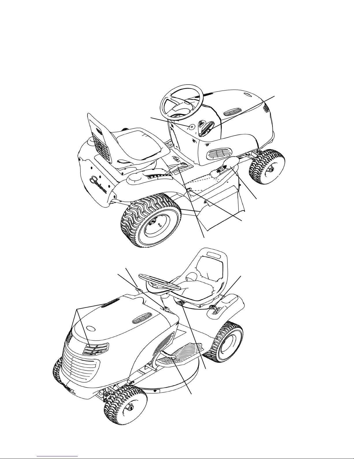
Figure 1
Ignition Switch
Headlight Switch
Drive Pedal
Start Foot Switch
Cutting Height Adjustment Lever
Mowing Attachment
Engagement Lever
Engine Air
Inlet Vents
Throttle Control Lever
Park Brake Lever
Foot Brake Pedal
Seat Adjustment Lever
Page 7

Rev 3 18/07/2014 Page 7 Model Number A12612A
The controls and their
functions are as
follows;
Ignition switch-
Used to start and stop engine.
Insert key, turn key all the way
right to start (3rd) position to
start engine. When key is
released from start (3rd)
position it will return to on |
(2nd) position. Turn key all the
way left to off O (1st) position
to stop engine. Remove key
from off O (1st) position to lock
ignition switch.
Throttle control lever-
Used to regulate engine speed
and cutter speed. Pull lever fully
back for slow engine speed.
Push lever forward to the
orange line for fast engine
speed.
Choke control-
Used to start a cold engine.
Push throttle control lever up
into the choke position to start
cold engine. Pull throttle control
lever down into the orange
range after engine has started.
Headlight switch-
Used to turn headlight on or off.
With ignition switch in on |
(2nd) position, toggle switch
lever back to on | position to
turn headlights on. toggle
switch lever forward to off O
position to turn headlights off.
Mowing attachment
clutch/brake control-
Used to start and stop mowing
attachment. With engine
running at fast speed, ease
handle fully backward to on |
position to start mowing
attachment. Push handle fully
forward to off O position to stop
mowing attachment.
Cutting height adjustment
lever-
Used to change the mowing
attachment cutting height. To
raise cutting height, pull lever
towards you and up, stop at
desired cutting height and push
lever into adjacent notch. To
lower cutting height, pull
towards you and lower the lever
to desired height and push lever
into adjacent notch.
Drive pedal-
Used to control an infinitely
va r i abl e g r ou n d s pee d
between zero and maximum in
forward or reverse. Also to
select neutral. With engine
running push down on front of
pedal to travel forward. With
engine running push down on
back of pedal to travel in
reverse. When pressure is
released from front or back of
pedal it will return to neutral
position. It is not necessary to
return to neutral before
changing from forward to
reverse or reverse to forward.
Foot brake pedal-
Used to stop machine travel
before setting park brake. Push
pedal down to apply brake.
Remove foot from pedal to
release brake.
Park brake lever-
Us ed to ke ep mac hine
stationary. With drive pedal in
neutral position and machine
stationary push lever down and
away from you to the ‘ON’
position to apply brake. To
release brake simply bump lever
down and towards you, the
spring tension will return the
lever to the ‘OFF’ position.
NOTE– Applying park
brake while machine is
m o v i n g a n d / o r
attempting to drive off
with the park brake not
fully in the off position
will damage the teeth of
the large sprocket.
Start Foot switch -
Used to ensure drive is in
neutral when starting engine
electrically. Place right foot on
and depress foot switch to start
engine with ignition key.
Fuel tap knob-
Used to shut off fuel line when
machine is transported or not in
operation to prevent fuel
leakage. Remove left hand side
cover and locate fuel tap at the
bottom of the fuel tank. Turn
fuel tap knob to right 1/4 turn
to off position to shut fuel line.
Turn fuel tap knob to left 1/4
turn to on position to open fuel
line.
The instruments and
THEIR functions are as
follows;
Hourmeter-
Used to indicate the number of
hours the engine has operated.
Note:- If the ignition switch is in
the on position with the engine
off the hourmeter will continue
to operate.
Fuel level windows-
Used to indicate fuel remaining
in fuel tank.
Oil level dipstick-
Used to indicate oil level in
engine when engine is not
running. (Refer to engine
owners manual for instructions
on checking engine oil level)
STARTING ENGINE
Electric starter:
Cold engine: Check engine oil
level, check fuel level, open fuel
line. To start engine, place
throttle control lever into choke
position, ensure mowing
attachment clutch/brake control
(manual or electrical) is in the
off O position, place right foot
on and depress start foot
switch , insert key in ignition
switch, turn key all the way
right to start (3rd) position,
release key when engine has
started. Note: Continuous
(Continued on page 8)
OPERATING INSTRUCTIONS
Page 8

Rev 3 18/07/2014 Page 8 Model Number A12612A
cranking for more than 15
seconds can damage the starter
motor. Short starting cycles
give best starter motor life.
Allow starter motor to cool for 2
minutes before attempting to
restart engine. After engine
starts, move throttle control out
of the choke position and into
the orange range, move throttle
control lever to obtain desired
engine speed.
Hot engine:
To start engine, place throttle
control slightly past slow
position, ensure mowing
attachment clutch/brake control
(manual or electrical) is in the
off O position, place right foot
on and depress foot switch
plate, insert key in ignition
switch, turn key all the way
right to start (3rd) position,
release key when engine has
started. Move throttle control lever
to obtain desired engine speed.
STOPPING ENGINE
When stopping engine, ensure
mowing attachment clutch/
brake control (manual or
electrical) is in the off position,
return throttle to slow position,
turn ignition switch to the off O
(1st) position.
DRIVING - TO TRAVEL
MACHINE FORWARD OR
REVERSE:
With engine running set
throttle control lever to obtain
desired engine speed. Apply
downward pressure on front
of drive pedal with toes to
travel forward, or apply
downward pressure on back of
drive pedal with heel to travel
in reverse. It is not necessary
to apply foot brake before
changing from forward to
reverse or reverse to forward.
The amount of pressure can
be used to control the ground
speed, light pressure will give
a slow ground speed, heavy
pressure will give a fast
ground speed. Heavy pressure
may also be required when
travelling up slopes or when
heavy loads are being towed
or carried. Excessive pressure
should not need to be applied
to the drive pedal to obtain a
fast ground speed. When
operating the mower on
slopes greater than 10
degrees but less than 15
degrees for a prolonged
period, you may experience
minor clutch fade, should this
occur, vary your mowing style
eg: mow around some flat
areas, then the slope followed
by the flat area again. This
will allow the drive to cool
before travelling up the slope
again.
NOTE:
When mowing slopes
keep clutch pedal in
forward or reverse,
depending on the
direction of the machine.
The low gearing will
prevent it from picking
up excessive speed. If
very steep, it may be
necessary to throttle
back slightly and or
apply a light pedal
pressure to the opposite
clutch plate. i.e. move
clutch pedal into reverse
when going forward
down a slope or into
forward when reversing
down a slope. Ensure
that when pressure is
applied to the drive pedal
the back wheel/s start
rotating or damage will
occur to drive system.
NOTE– Do Not mow
either direction on slopes
beyond 15 degrees (1 in
3.75).
TO STOP MACHINE
TRAVEL
ENGINE RUNNING:
The drive pedal may be used to
stop the machine. If traveling
forward push the pedal into
reverse until machine stops,
then bring the pedal back to
neutral position or vice versa if
traveling in reverse. Should
failure of the drive system occur
during operation use the foot
brake pedal to stop machine
travel.
ENGINE STOPPED:
Use foot brake pedal only.
NOTE:
Damage to clutch cone
will occur if clutch pedal
is used to stop machine
travel with the engine
not running.
MANOEUVRING:
Due to the heel and toe type
action of the drive pedal, it is
possible to take the machine
straight from forward to reverse
and vice versa without applying
the foot brake. This instant
forward and reverse operation
in conjunction with it tight
turning radius makes the
machine very maneuverable
and the sharpest turns can be
negotiated easily and quickly.
Note:
T a k e c ar e w h e n
reversing, always look in
the direction of intended
travel before changing
direction.
DIFFERENTIAL OPTION:
The differential is used to
permit the back wheels to
rotate at different speeds when
mane uvering tight turns
avoiding wheel slip which may
damage the lawn.
TRANSPORTING
If your machine is transported
regularly from site to site,
especially by trailer, it is
recommended to either adjust
clutch plates wide apart (retigh ten bolts) or place
cardboard between clutch cone
and clutch plates to avoid
damaging the clutch cone.
Page 9

Rev 3 18/07/2014 Page 9 Model Number A12612A
BEFORE EACH USE
Change engine oil - Clean machine - Lubricate as per required
DATE / / HOURS..........................DEALER................................................
MAINTENANCE SCHEDULE
Check engine oil level, adjust if required
Check engine air cleaner foam pre-cleaner, service if req
Check engine rotating screen/finger guard, clean if req
Check engine air inlet console screen, clean if required
Check operation of safety switches, service if required
Check foot brake operation, adjust if required
Lubricate as per required
Check tyre pressures, adjust if required
Grease stub axles
Check mowing attachment cutter blades, bolts, nuts, disc/s,
housing, and guards for wear or damage, replace if required
Check for loose fasteners, tighten if required
BEFORE STORAGE
EVERY 5 HOURS
Check engine oil level, adjust if required Lubricate chains (motorcycle chain lube preferred)
Check engine air cleaner foam pre-cleaner, service if req
Check engine rotating screen/finger guard, clean if required
Check engine air inlet console screen, clean if required*
*Service more often under dusty conditions, or where air born debris is present
1 MONTH OR 5 HOURS WHICH EVER OCCURS FIRST
Change engine oil
Check engine air cleaner foam pre-cleaner, service if required
Check engine rotating screen/finger guard, clean if required
Check engine air inlet console screen, clean if required
Check foot brake operation, adjust if required
Check operation of safety switches, service if required
Check tyre pressures, adjust if required
Grease stub axles
Check for loose fasteners, tighten if required
Check clutch arm action, adjust if required
Check mowing attachment cutter blades, bolts, nuts, disc/s, housing , and guards for damage, replace if required
DATE / / HOURS..........................DEALER................................................
*Service more often under dusty conditions, or where air borne debris is present
3 MONTH OR 25 HOURS WHICH EVER OCCURS FIRST
Change engine oil if operating under heavy load or high ambient
temperature
Check engine air cleaner foam pre-cleaner, service if required *
Check engine rotating screen/finger guard, clean if required *
Check engine air inlet console screen, clean if required *
Check foot brake operation, adjust if required
Check operation of safety switches and replace if required
Check tyre pressures, adjust if required
Grease stub axles *
Check for loose fasteners, tighten if required
Check battery condition, service if required
Check mowing attachment cutter blades, bolts, nuts, disc/s, housing, and guards for wear or damage, replace if required
Lubricate steering & drive chains (motorcycle chain lube preferred)
*Service more often under dusty conditions, or where air borne debris is present
6 MONTH OR 50 HOURS WHICH EVER OCCURS FIRST
Change engine oil
If fitted clean engine exhaust spark arrester
Check engine air cleaner foam pre-cleaner , service if required *
Check engine rotating screen/finger guard , clean if required *
Check engine air inlet console screen clean if required *
Check foot brake operation and lining for ware, adjust or replace if
req. Check operation of safety switches, service if required
Check tyre pressures, adjust if required
Grease stub axles *
Check steering chain and sprockets or wear, adjust if required
Check mowing attachment cutter blades, bolts, nuts, disc/s, housing, and guards for wear or damage, replace if required
Check clutch arm action, adjust if required
Check belts for wear or damage, replace if required
Check drive chain and sprockets for wear, replace if required
If fitted dismantle, clean, re-grease, and reassemble differential
If fitted check mowing attachment brake pad for wear, replace if
required
If fitted check mowing attachment electric clutch brake air gap,
adjust if req
Check for loose fasteners, tighten if required
Check drive clutch plates and cone for wear or damage, adjust or
service if req
Check battery condition, service if required
Check & tighten if necessary the clamp around the lower boss of
the steering box where it mounts onto the lower steering shaft
Lubricate steering & drive chains (motorcycle chain lube preferred)
DATE / / HOURS..........................DEALER................................................
Page 10

Rev 3 18/07/2014 Page 10 Model Number A12612A
9 MONTHS OR 75 HOURS WHICH EVER OCCURS FIRST
Change engine oil if operating under heavy load or high ambient
temperature
Check engine air cleaner foam pre-cleaner, service if required *
Check engine rotating screen/finger guard, clean if required *
Check engine air inlet console screen, clean if required *
Check foot brake operation, adjust if required
Check operation of safety switches and replace if required
Check tyre pressures, adjust if required
Grease stub axles *
Check for loose fasteners, tighten if required
Check battery condition, service if required
Check mowing attachment cutter blades, bolts, nuts, disc/s, housing, and guards for wear or damage, replace if required
Lubricate steering & drive chains (motorcycle chain lube preferred)
12 MONTHS OR 100 HOURS WHICH EVER OCCURS FIRST
If fitted replace engine oil filter.
Change engine oil.
Check engine spark plug, clean, adjust, or replace if required.
If fitted clean engine exhaust spark arrester.
Check engine air cleaner foam pre-cleaner, service if required *.
Check engine air cleaner cartridge, service if required*.
Clean engine cooling system*.
Check engine air inlet console screen, clean if required *.
Replace in-line fuel filter.
Check foot brake operation and lining for ware, adjust or replace if
req.
Grease stub axles *.
Check tyre pressures, adjust if required.
Check operation of safety switches, service if required.
Check steering chain an sprockets or wear, adjust if required.
Check drive chain and sprockets for wear, replace if required.
Check belts for wear or damage, replace if required.
Check clutch arm action, adjust if required.
Re-tension rear wheel adaptor retaining nut/s.
If fitted re-tension differential outer gear retaining bolts.
Check battery condition, service if required.
If fitted check mowing attachment brake pad for wear, replace if
req.
If fitted check mowing attachment electric clutch brake air gap,
adjust if req.
Check for loose fasteners, tighten if required.
Check drive clutch plates and cone for wear or damage, adjust or
service if required.
Check clutch arm action, adjust if required.
Check mowing attachment cutter blades, bolts, nuts, disc/s, housing, and guards for wear or damage, replace if required.
Check & tighten if necessary the clamp around the lower boss of
the steering box where it mounts onto the lower steering shaft
Lubricate steering & drive chains (motorcycle chain lube preferred)
*Service more often under dusty conditions, or where air borne debris is present
DATE / / HOURS..........................DEALER................................................
DATE / / HOURS..........................DEALER................................................
*Service more often under dusty conditions, or where air borne debris is present
15 MONTHS OR 125 HOURS WHICH EVER OCCURS FIRST
Change engine oil if operating under heavy load or high ambient
temperature.
Check engine air cleaner foam pre-cleaner, service if required *.
Check engine rotating screen/finger guard, clean if required *.
Check engine air inlet console screen, clean if required *.
Check foot brake operation, adjust if required.
Check operation of safety switches and replace if required.
Check tyre pressures, adjust if required.
Grease stub axles *.
Check battery condition, service if required.
Check for loose fasteners, tighten if required.
Check mowing attachment cutter blades, bolts, nuts, disc/s, housing, and guards for wear or damage, replace if required.
Lubricate steering & drive chains (motorcycle chain lube preferred)
*Service more often under dusty conditions, or where air borne debris is present
DATE / / HOURS..........................DEALER................................................
18 MONTHS OR 150 HOURS WHICH EVER OCCURS FIRST
*Service more often under dusty conditions, or where air borne debris is present
DATE / / HOURS..........................DEALER................................................
Change engine oil.
If fitted clean engine exhaust spark arrestor.
Check engine air cleaner foam pre-cleaner, service if required *.
Check engine rotating screen/finger guard, clean if required *.
Check engine air inlet console screen, clean if required *.
Check foot brake operation and lining wear, adjust or replace if req.
Check operation of safety switches, service if required.
Check tyre pressures, adjust if required.
Grease stub axles *.
Check steering chain and sprockets or wear, adjust if required.
Check belts for wear or damage, replace if required.
Check drive chain and sprockets for wear, replace if required.
If fitted dismantle, clean, re-grease, and reassemble differential.
If fitted check mowing attachment brake pad for wear, replace if
required.
If fitted check mowing attachment electric clutch brake air gap, adjust if req.
Check drive clutch plates and cone for wear or damage, adjust/
service if req.
Check clutch arm action, adjust if required.
Check battery condition, service if required.
Check for loose fasteners, tighten if required.
Check mowing attachment cutter blades, bolts, nuts, disc/s, housing,
and guards for wear or damage, replace if required.
Check & tighten if necessary the clamp around the lower boss of the
steering box where it mounts onto the lower steering shaft
Lubricate steering & drive chains (motorcycle chain lube preferred)
Page 11

Rev 3 18/07/2014 Page 11 Model Number A12612A
21 MONTHS OR 175 HOURS WHICH EVER OCCURS FIRST
Change engine oil if operating under heavy load or high ambient
temperature.
Check engine air cleaner foam pre-cleaner, service if required *.
Check engine rotating screen/finger guard, clean if required *.
Check engine air inlet console screen, clean if required *.
Check foot brake operation, adjust if required.
Check operation of safety switches and replace if required.
Check tyre pressures, adjust if required.
Grease stub axles *.
Check battery condition, service if required.
Check for loose fasteners, tighten if required.
Check mowing attachment cutter blades, bolts, nuts, disc/s, housing, and guards for wear or damage, replace if required.
Lubricate steering & drive chains (motorcycle chain lube preferred)
24 MONTHS OR 200 HOURS WHICH EVER OCCURS FIRST
*Service more often under dusty conditions, or where air borne debris is present
DATE / / HOURS..........................DEALER................................................
If fitted replace engine oil filter.
Change engine oil.
Check engine spark plug, clean, adjust, or replace if required.
If fitted clean engine exhaust spark arrestor.
Check engine air cleaner foam pre-cleaner , service if required *.
Check engine air cleaner cartridge, service if required.
Clean engine cooling system*.
Check engine air inlet console screen , clean if required *.
Replace in-line fuel filter.
Check foot brake operation and lining for ware, adjust or replace if
req.
Check operation of safety switches, service if required.
Check tyre pressures, adjust if required.
Grease stub axles *
Check steering chain and sprockets or wear, adjust if required
Check belts for wear or damage, replace if required.
Check drive chain and sprockets for wear, replace if required.
If fitted re-tension differential outer gear retaining bolts.
Re-tension rear wheel adapter retaining nut/s.
If fitted check mowing attachment brake pad for wear, replace if
required.
If fitted check mowing attachment electric clutch brake air gap,
adjust if req.
Check clutch arm action, adjust if required
Check battery condition, service if required
Check for loose fasteners, tighten if required
Check mowing attachment cutter blades, bolts, nuts, disc/s, housing , and guards for wear or damage, replace if required.
Check & tighten if necessary the clamp around the lower boss of
the steering box where it mounts onto the lower steering shaft
Lubricate steering & drive chains (motorcycle chain lube preferred)
*Service more often under dusty conditions, or where air borne debris is present
DATE / / HOURS..........................DEALER................................................
27 MONTHS OR 225 HOURS WHICH EVER OCCURS FIRST
Change engine oil if operating under heavy load or high ambient
temperature.
Check engine air cleaner foam pre-cleaner, service if required *.
Check engine rotating screen/finger guard, clean if required *.
Check engine air inlet console screen, clean if required *.
Check foot brake operation, adjust if required.
Check operation of safety switches and replace if required.
Check tyre pressures, adjust if required.
Grease stub axles *.
Check battery condition, service if required.
Check for loose fasteners, tighten if required.
Check mowing attachment cutter blades, bolts, nuts, disc/s, housing, and guards for wear or damage, replace if required
Lubricate steering & drive chains (motorcycle chain lube preferred)
*Service more often under dusty conditions, or where air borne debris is present
DATE / / HOURS..........................DEALER................................................
30 MONTHS OR 250 HOURS WHICH EVER OCCURS FIRST
Change engine oil.
If fitted clean engine exhaust spark arrestor.
Check engine air cleaner foam pre-cleaner , service if required *.
Check engine rotating screen/finger guard , clean if required *.
Check engine air inlet console screen , clean if required *.
Check foot brake operation and lining for ware, adjust or replace if
req.
Check operation of safety switches, service if required.
Check tyre pressures, adjust if required.
Grease stub axles *.
Check steering chain an sprockets or wear, adjust if required.
Check mowing attachment cutter blades, bolts, nuts, disc/s, housing, and guards for wear or damage, replace if required.
Check belts for wear or damage, replace if required
Check drive chain and sprockets for wear, replace if required
If fitted dismantle, clean, re-grease, and reassemble differential
If fitted check mowing attachment brake pad for wear, replace if
required
If fitted check mowing attachment electric clutch brake air gap,
adjust if req,
Check drive clutch plates and cone for wear or damage.
adjust or service if required.
Check clutch arm action, adjust if required.
Check battery condition, service if required.
Check for loose fasteners, tighten if require
Check & tighten if necessary the clamp around the lower boss of
the steering box where it mounts onto the lower steering shaft
Lubricate steering & drive chains (motorcycle chain lube preferred)
*Service more often under dusty conditions, or where air borne debris is present
DATE / / HOURS..........................DEALER................................................
Page 12

Rev 3 18/07/2014 Page 12 Model Number A12612A
33 MONTHS OR 275 HOURS WHICH EVER OCCURS FIRST
Change engine oil if operating under heavy load or high ambient
temperature
Check engine air cleaner foam pre-cleaner, service if required *
Check engine rotating screen/finger guard, clean if required *
Check engine air inlet console screen, clean if required *
Check foot brake operation, adjust if required
Check operation of safety switches and replace if required
Check tyre pressures, adjust if required
Grease stub axles *
Check mowing attachment cutter blades, bolts, nuts, disc/s, housing , and guards for wear or damage, replace if required
Check battery condition, service if required
Check for loose fasteners, tighten if required
Lubricate drive & steering chains (motorcycle chain lube preferred)
*Service more often under dusty conditions, or where air borne debris is present
DATE / / HOURS..........................DEALER................................................
36 MONTHS OR 300 HOURS WHICH EVER OCCURS FIRST
If fitted replace engine oil filter
Change engine oil
Check engine spark plug, clean, adjust, or replace if required
If fitted clean engine exhaust spark arrestor
Check engine air cleaner foam pre-cleaner, service if required *
Check engine air cleaner cartridge, service if required
Clean engine cooling system*
Check engine air inlet console screen , clean if required *
Replace in-line fuel filter
Check foot brake operation and lining for ware, adjust or replace if
req.
Check operation of safety switches, service if required
Check tyre pressures, adjust if required
Grease stub axles *
Check steering chain an sprockets or wear, adjust if required
Check mowing attachment cutter blades, bolts, nuts, disc/s, housing, and guards for wear or damage, replace if required
Check belts for wear or damage, replace if required
Check drive chain and sprockets for wear, replace if required
If fitted re-tension differential outer gear retaining bolts
Re-tension rear wheel adapter retaining nut/s
If fitted check mowing attachment brake pad for wear, replace if
required
If fitted check mowing attachment electric clutch brake air gap,
adjust if req
Check drive clutch plates and cone for wear or damage, adjust/
service if req
Check clutch arm action, adjust if required
Check battery condition, service if required
Check for loose fasteners, tighten if required
Check & tighten if necessary the clamp around the lower boss of
the steering box where it mounts onto the lower steering shaft
Lubricate drive & steering chains (motorcycle chain lube preferred)
*Service more often under dusty conditions, or where air borne debris is present
DATE / / HOURS..........................DEALER................................................
MAINTENANCE INSTRUCTIONS
Before servicing, disconnect spark
plug wire and ground it,
disconnect battery at negative
terminal, to prevent accidental
starting.
Reference to the left or right side of
the machine is determined by sitting in
the operating position.
IMPORTANT
If operating in conditions such as
those mentioned below, engine oil, air
filtering, chassis lubrication, greasing
and adjustments should be serviced
at more frequent intervals than
specified in this booklet.
a. Mowing in damp or wet conditions.
b. Mowing in rough or dusty
conditions.
c. Mowing in hilly areas under heavy
load.
Ensure machine has park brake
engaged when attempting to
start engine. Disengage park
brake before applying drive
pressure to clutch pedal.
Never alter factory setting of
maximum engine R.P.M.
STEERING –
Check, lubricate & adjust the steering chain
if necessary
Check & replace steering tie rod ball joints
if worn.
DIFFERENTIAL -
For models fitted with a differential it is
essential that the maintenance schedule
supplied be performed by your COX
INDUSTRIES Dealer. This will ensure the
differential has trouble free operation and
long service life.
CHECK ENGINE OIL LEVEL - Refer to
engine owners manual for correct method
to check engine oil level.
CHANGE ENGINE OIL -
Refer to engine owners manual for correct
method to change engine oil.
CHECK ENGINE AIR CLEANER FOAM
PRE-CLEANER -
Refer to engine owners manual for correct
method to check and service engine air
cleaner foam pre-cleaner.
CHECK ENGINE INLET VENTS -
If Vents are more than one quarter blocked
by debris clean Vents.
Wipe vents with hand, rag or brush to
remove debris from vent openings.
CHECK ENGINE ROTATING
SCREEN/FINGER GUARD –
Refer to engine owners manual for correct
method to check and clean engine rotating
screen /debris guard.
Page 13

Rev 3 18/07/2014 Page 13 Model Number A12612A
CHECK FOOT BRAKE
OPERATION -
Measure the distance between the under
side of the pedal rubber to footrest by
holding pedal down using hand pressure. If
less than 50mm (2”) adjust brake. Adjust
brake by tightening the nyloc nut on brake
pull rod (pedal end) to give 90mm (3 1/2”)
between the brake pedal rubber and
footrest (using hand pressure on brake
pedal).
CHECK TYRE PRESSURES –
Adjust front and rear tyre pressure to
100kPa (15psi).
CHECK OPERATION OF SAFETY
SWITCHES -
Foot Switch - Sit on seat with cutter
disengaged, (manual or electric control)
attempt to start engine without using the
foot switch. Engine should not start.
Disengagement Switch - Sit on seat with
foot on foot switch and cutter engaged,
(manual or electric control) attempt to start
engine. Engine should not start.
Seat Switch - Sit on seat and start engine,
engage cutter, (manual or electric control)
and lift weight from seat. Engine should
stop.
CHECK FOR LOOSE
FASTENERS -
TORQUE SETTINGS
1/4” UNC BOLT/NUT 10Nm (84lbf in)
5/16” UNF BOLT 23Nm (17lbf ft)
5/16” UNC BOLT/NUT 20Nm (180lbfin)
3/8” UNF BOLT 41Nm (30lbf ft)
3/8” UNC BOLT/NUT 36Nm (27lbf ft)
7/16” UNF BOLT 68Nm (50lbf ft)
1/2” UNC BOLT/NUT 90Nm (66lbf ft)
3/8” UNF BOLT P/N B0620F CLUTCH SHAFT
ONLY 35Nm (26lbf ft)
6mm BOLT/NUT 9Nm (80lbf in)
8mm BOLT/NUT 30Nm (22lbf ft)
20mm NUT 100Nm (74lbf ft)
5/8” UNF NUT 100Nm (74lbf ft)
BATTERY MAINTENANCE-
When not in use, a battery discharges by
as much as 1% a day, more when the
climate is warm. To make up for this
loss, a boosting charge should be given
once a month. Disconnect battery
terminals to charge, then allow to stand
minimum 1/2hr before re-connecting. If
a battery is not used for a period of more
than three (3) months, the terminals
should be disconnected and trickle
charged at two (2) amps for two (2)
hours once every three (3) months or
before use.
GREASE STUB AXLES -
Clean grease nipple, use grease gun and
general purpose grease to force old grease
from top and bottom of front axle bushes.
Jack up front of machine if grease is not
released from bottom of bush.
REMOVE MOWING
ATTACHMENT -
With engine off fully lower mowing
attachment, and using spring hook and
tommy bar supplied, disconnect the three
springs below the front axle beam (warning,
springs are under tension) remove
attachment pivot rod. Disconnect rear lifting
link, push attachment to the rear to loosen
vee belt, remove vee belt from the rear
pulley. Turn steering to full left hand lock
and slide attachment from under machine
to the right hand side. To refit, reverse the
above procedure.
REPLACE P.T.O. TO CUTTER BELT -
Engage park brake, place mowing
attachment in lowest position remove the
front ends of the three springs from under
front axle beam using spring hook and
tommy bar supplied, (caution springs are
under tension) remove R Pin from rear
lifting link, disconnect link from mowing
attachment and push mowing attachment
to the rear to loosen belt. Remove belt
from pulleys and replace with new belt,
reverse the above procedure to re-tension
belt.
REPLACE BLADES -
Stop engine. Remove spark plug lead. Lift
windrower and raise cutter to highest
position. If necessary simply remove the
blade bolt and nut using a suitable spanner
and replace all blades, bolts and nuts. For
40" mowing attachment it is advisable to
remove mowing attachment for blade
replacement. Tighten blade nut to (3640Nm). Do not over-tighten.
CLUTCH PLATE ADJUSTMENT – Start
engine and run for approx 1 min at about
half throttle, switch engine off, loosen the
four square head set screws on the clutch
plates using the tube spanner (AM006C1)
and tommy bar (AM007). Insert the two
clearance gauges supplied, one between
the forward clutch plate and cone and the
other in the reverse side and hook them
onto the intershaft. Slide both clutch plates
against the clearance gauges and clutch
cone. Tighten the set screws firmly onto the
flat machined on the intershaft. (Do not
over-tighten set screws). Remove gauges.
Under no circumstances allow
grease or oil to come into
contact with the Clutch Cone
or Clutch Plates. Should this
problem occur, clean off
immediately with petrol whilst
surface areas are cool and
allow to dry before operating
machine.
REPLACE DRIVE CHAIN -
Engage park brake, jack up rear of
machine, and remove L/H wheel. Push
chain tensioner arms, one at a time, away
from chain and using a suitable spanner
tighten pivot bolt lock nuts to hold them
out. Release park brake then turn rear axle
to bring chain into a suitable position for
removal of the chain connecting link.
Remove connecting link and chain. Inspect
both sprockets for wear or damage, replace
if necessary. Install new chain and
connecting link with the link clip between
the wheel and chain. Release pivot arm
nuts until arms move freely back to chain.
Engage park brake, install wheel and lower
machine.
SEAT ADJUSTMENT -
Pull seat adjustment lever to the left, then
slide seat backwards or forward to desired
position and release lever, ensure lever
returns fully to right and seat is locked in
position.
CLEANING AND POLISHING PLASTIC
BONNET & FOOT PAN -
To keep scratches on bonnet to minimum,
do not rub or brush off with bare hands, use
a soft cloth or a light flow of compressed
air. For dirt, wash with a steady stream of
water only (no detergent), then blow off
excess water with air. To polish remove
excess dust or dirt. When surface is dry,
spray on an automotive type plastic
preservative and leave on for 30 to 60
seconds. Using a dry soft cloth (i.e.
cheesecloth) wipe off to bring up lustre.
CLEANING MACHINE WITH WATER
PRESSURE –
Allow machine to cool down (min 2 hrs)
before hosing down. Start engine and
engage drive and cutting systems to clear
water from pulleys, belts and clutch areas.
Stop engine and allow machine to dry.
Lubricate as per lubrication chart before
storage.
GENUINE SPARE PARTS -
Always use Genuine Cox Factory Made
Spare Parts. Use of non genuine COX
spares will void your warranty.
SAFETY FIRST -
The use of any mechanical appliance can
cause injury if incorrect procedures are
used. Please ensure that all family
members of intended operators read this
manual and safety instructions thoroughly.
MAINTENANCE INSTRUCTIONS cont.
We are proud that you have purchased a Cox product and urge you to follow these instructions
to obtain the maximum life for your machine. If in doubt check with your supplier.
Page 14
Rev 3 18/07/2014 Page 14 Model Number A12612A
TOOL KIT
ITEM PART NUMBER DESCRIPTION QTY
1 AM006C1 Spanner, Tube, Clutch Plate 1
2 AM007 Bar, Tommy 1
3 AM295 Spanner, Tube, Spark Plug 1
4 13126 Gauge, Clutch Clearance 2
5 13127 Hook, Spring Pull 1
6 90134 Key, Ignition Switch 2
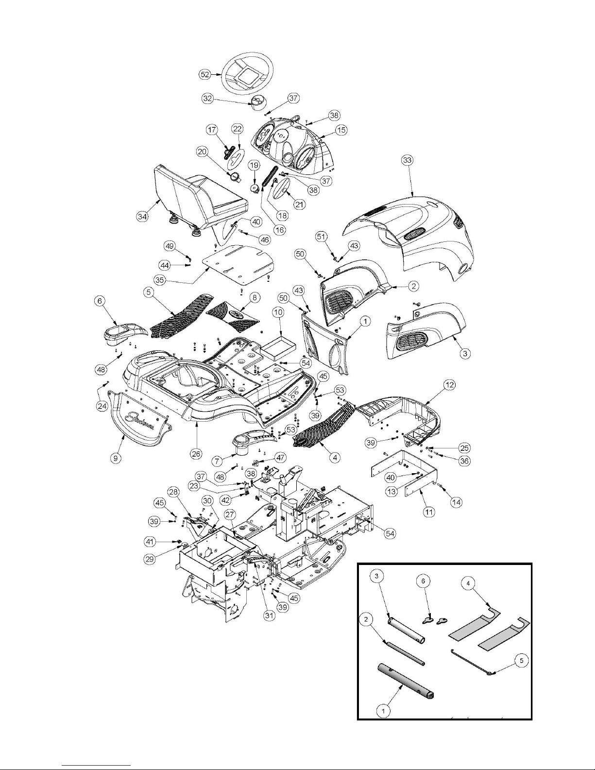
BODY COMPONENTS & TOOL KIT
TOOL KIT
Page 15

Rev 3 18/07/2014 Page 15 Model Number A12612A
BODY COMPONENTS & TOOL KIT
ITEM PART NUMBER DESCRIPTION QTY
1 A126233 Battery Cover 1
2 A126234 Left Side Cover 1
3 A126235 Right Side Cover 1
4 90045 Right Foot Mat 1
5 90046 Left Foot Mat 1
6 A126247 Hand Brake Shroud 1
7 A126248 Height Adjustment Shroud 1
8 90072 Centre Foot Mat 1
9 90075 Mud Flap 1
10 90076 Battery Spill Mat 1
11 A126220R Support, Bumper Bar 1
12 A126270 Bumper Bar 1
13 NHM8 Nut 2
14 SH0825M Screw 2
15 A126232 Dashboard 1
16 90063 Rubber Dash Insert, Disengagement 1
17 90064 Rubber Dash Insert, Throttle 1
18 90128 Switch, Light 1
19 90129 Ignition Switch 1
20 AM211 Hour Meter 1
21 DEC284 Decal, Cutter Slot And Light 1
22 DEC283 Decal, Throttle Control 1
23 90096 Console Lug 1
24 90132 Rivet, Plastic 5
25 90140 Bush, Bumper 6
26 90205 Pan, Foot, Plastic, Red 1
DEC127 Decal,Warning, Mount this side only 1
DEC178 Badge, Foot Pan 1
27 90251 Clip, Cover, Inspection, Top, 1
28 90258 Bracket, Lock, Handle, Park Brake 1
29 90259 Bracket, Clip, Tall 2
30 90260 Bracket, Clip, Short 2
31 A102038Z Bracket, Adjust, Height, Cut 1
32 A102364 Adaptor, Console-Steering Wheel 1
33 A126385 Sub-Assy, Bonnet 16.5HP 1
A126285 Sub-Assy, Bonnet 21HP 1
34 Sub-Assy, Seat+Adjuster+Hinge 1
35 A126447R Cover, Inspection, Top 1
36 B0625M Bolt 6
37 BHSSM5X12 Screw, Button 9
38 NM5NT Nut 7
39 NM6NT Nut 32
40 NM8NT Nut 4
41 RECS4 Receptacle, 1/4 Turn, Clip-On, 4 4
42 RECS6 Receptacle, 1/4turn, Slip On, 6 6
43 RETP6 Retainer, 1/4turn, Plastic, 6 6
44 RETS4 Retainer, 1/4 Turn, Steel, 4 4
45 SH0616M Screw 26
46 SH0825M Screw 2
47 SP1PNOSM Switch, Plunger 1
48 SPPK5X16 Screw, Pan 8
49 STDR414 Stud, 1/4 Turn, Bail, 4x14 4
50 STDR614 Stud, 1/4turn, Ring, 6x14 4
51 STDR622 Stud, 1/4turn, Ring, 6x22 2
52 SW14H Wheel, Steering, 14" 1
53 W06MN Washer, Flat 18
54 WG06x08 Grommet 6
Page 16

Rev 3 18/07/2014 Page 16 Model Number A12612A
BONNET COMPONENTS (18.5HP & 21HP ONLY) BONNET COMPONENTS
Page 17

Rev 3 18/07/2014 Page 17 Model Number A12612A
BONNET COMPONENTS
ITEM PART NUMBER DESCRIPTION QTY
1 15132 Globe 1
2 A126221R Hinge, Bonnet New Era 1
3 90038 Head Light Reflector 1
4 90039 Head Light Lens 1
5 A126240 Air Duct Intake 1
6 A126241 Grille 1
7 A126242 Left Bonnet Vent 1
8 A126243 Right Bonnet Vent 2
9 90130 Buffer, Rubber 2
10 9003108G Bonnet incl Mountings and Spacers 1
11 A126044 Mounting, Side, Bonnet 2
12 A126045 Spacer, Mounting, Side, Bonnet 2
13 90147 Shield, Heat, Bonnet 16.5HP 1
A126147 Shield, Heat, Bonnet 21HP 1
14 AM096 Clip 1
15 DEC180 Badge, Bonnet New Era 3
16 PR0207 Rivet, Heat Shield 3
17 SPPK5X16 Screw 22
18 SPST04CX0.37 Screw 18.5HP 21HP 1
DEC276 Decal, Bonnet, Stockman PRO, LH 1
DEC277 Decal, Bonnet, Stockman PRO, RH 1
Page 18

Rev 3 18/07/2014 Page 18 Model Number A12612A
SEAT COMPONENTS
Page 19

Rev 3 18/07/2014 Page 19 Model Number A12612A
SEAT COMPONENTS
ITE
M PART NUMBER DESCRIPTION QTY
1 13060 Spring, Seat 2
2 14128 Cap, Seat Spring 2
3 A126050 Seat 1
4 A126052 Kit,Adjust,Seat,4" Travel 1
4.1 Adjuster 1
4.2 Runner 1
4.3 BHSSC0512 Replacement Screw 4
4.4 13247 Replacement Washer 4
5 A126442Z Bracket, Hinge, Left 1
6 A126444Z Bracket, Hinge, Right 1
7 A126449R Base, Seat 1
8 BHSSC0512 Screw, Button 2
9 N05CN Nut 6
10 SP1PNCSM Switch, Plunger 1
11 W05M202 Washer, Flat 2
12 WS050216 Washer, Lock, Spring 4
Page 20

Rev 3 18/07/2014 Page 20 Model Number A12612A
ENGINE & CONTROL COMPONENTS
Page 21

Rev 3 18/07/2014 Page 21 Model Number A12612A
ENGINE & CONTROL COMPONENTS
ITEM PART NUMBER DESCRIPTION QTY
1 13206 Valve, Drain, Oil 1
2 14107 Fuel Hose 1
3 90068 Fuel Tank 1
4 AM293 Petrol Tap 1
5 AM294 Grommet 1
6 CF01 Cap, Fuel 1
7 A126266 Throttle Control Handle 1
8 90078 Control, Throttle 1
9 13367 Exhaust Pipe 1
10 13368 Exhaust Bracket 1
11 Exhaust Gasket B&S 1
12 Engine 1
13 Screw 7
14 CHSS0512C Screw, Cap 2
15 Muffler, Exhaust, B&S 1
16 Clamp, Muffler, B&S 1
17 Nut, Hex Mach, B&S 1
18 Bolt, Round Head Square Neck, B&S 1
19 Deflector, Muffler, B&S 1
20 80025 Deflector, Exhaust Gas 1
21 Screw 3
22 90139 Clamp, Battery 1
23 90295R Plate, Base, Engine 1
24 A108104 Key 1
25 A116207Z Plate, Mounting, Engine, Left 1
26 A116208Z Plate, Mounting, Engine, Right 1
27 A126032 Pulley, Engine 1
28 B0845M Bolt 2
29 BHSSM5X12 Screw, Button 2
30 GS0505C Screw, Set 1
31 NCM6X1.6X9.5 Nut, Cage 1
32 NHCM8 Nut, Hex, Conelok 2
33 NM5NT Nut 2
34 SH0616M Screw 1
35 SH0724F Screw 1
36 SH0850M Screw 2
37 W041216 Washer, Flat 1
38 W051218 Washer, Flat 4
39 W071416 Washer, Flat 2
40 W072004 Washer, Flat 1
41 WS040816 Washer, Lock, Spring 1
42 WS050216 Washer, Lock, Spring 2
43 WS071008 Washer, Lock, Spring 1
Page 22

Rev 3 18/07/2014 Page 22 Model Number A12612A
Page 23

Rev 3 18/07/2014 Page 23 Model Number A12612A
WIRING DIAGRAM
ITEM PART NUMBER DESCRIPTION QTY
1 Battery, Automotive,12V,CMFU1,9PL,240CCA 1
SH0620M Screw, Battery 2
NHM6 Nut, Battery 2
2 90129 Switch, Ignition 1
90134 Key, Ign Switch 1
3 Engine 1
4 SP2PNONCSM Switch, Plunger, Disengagement 1
5 90128 Switch, Light 1
6 SP1PNCSM Switch, Plunger, Seat 1
7 AM159 Solenoid, 1
SH0616M Bolt, Solenoid 2
NM6NT Nut, Solenoid 2
8 15132 Globe 1
9 AM211 Hourmeter 1
10 SP1PNOSM Switch, Plunger, Foot 1
11 A126437 Harness, Wiring, Main 1
11.1 Fuse, Blade Type, 15 A, Blue 1
12 90138 Harness, Wiring, Headlight 1
13 A143112 Harness, Wiring, Engine 1
14 13115 Lead, Battery, Red, L=400 1
15 AM265 Lead, Battery, Red, L=490 1
16 15235 Lead, Battery, Black, 3 term 1
Page 24

Rev 3 18/07/2014 Page 24 Model Number A12612A
BRAKE COMPONENTS
Page 25

Rev 3 18/07/2014 Page 25 Model Number A12612A
BRAKE COMPONENTS
ITEM PART NUMBER DESCRIPTION QTY
1 A126262 Park Brake Handle 1
2 90264 Pivot, Brake Pedal 1
3 90219 Brace, Pivot, Brake Pedal 1
4 9007706D Pad, Pedal, Brake 1
5 A126420R Lever, Brake Pedal 1
6 90222 Link, Pull, Brake Rod 1
7 AM230 Bush - Plastic 2
8 B0620C Bolt 1
9 NF06CN Nut 2
10 90221 Rod, Brake 1
11 90024 Lever, Park Brake 1
12 9001506D Lever, Brake, Actuating 1
13 13023-02 Lining, Band Brake 1
14 1302305E Band, Brake incl Lining 1
15 13025 Nylon Bush, Brake Lever 1
16 RE14INT End, Rod, Stamp 1
17 N04F Nut 2
18 B0428F Bolt 1
19 WS040816 Washer, Lock, Spring 1
20 B0624C Bolt 1
21 B0832C Bolt 1
22 N08C Nut 1
23 W061216 Washer 2
24 W081616 Washer 2
25 WS081208 Washer, Spring 1
26 13079 Spring, Compression, Foot Brake Return 1
27 W041216 Washer 1
28 N07F Nut 1
29 NM6NT Nut 2
30 NM8NT Nut 5
31 SH0816M Screw 4
32 W071416 Washer 1
33 SH0616M Screw 2
Page 26

Rev 3 18/07/2014 Page 26 Model Number A12612A
STEERING COMPONENTS
Page 27

Rev 3 18/07/2014 Page 27 Model Number A12612A
STEERING COMPONENTS
ITEM PART NUMBER DESCRIPTION QTY
1 13012 Bush, Flanged, Nylon 1
2 AM25399J Disc, Universal Joint 1
4 A126008Z Shaft, Steering, Lower 1
5 A126018Z Pivot, Idler, Left 1
6 A126020Z Pivot, Idler, Right 1
7 A126024Z Pivot, Crank 1
8 A126030 Chain, Roller 1
9 A126022Z Crank, Steering 1
10 AM017C1 Steering Shaft Bush With Collar 2
11 A126016Z Idler, Chain, Steering 1
12 A126026Z Link, Adjust, Chain, Left 1
13 CP2-512 Pin, Split 2
14 NFM8 Nut, Hex, Flange, Serated 1
15 W051218 Washer 2
16 A126028Z Link, Adjust, Chain, Right 1
17 A126165Z Shaft, Steering, Top 1
18 A126167Z Shaft, Steering, Upper 1
19 A126174Z Yoke, Joint, Universal, Steering 2
20 AM017C1 Steering Shaft Bush With Collar 2
21 AM066 Steering Shaft Lock Collar 1
22 B0625M Bolt 8
23 B0630M Bolt 1
24 C05 Circlip, Ext, "E" Type 1
25 DEC177 Badge, Steering Wheel 1
26 DP10 Pin, Roll, Spring 1
27 GS0404C Screw, Set 1
28 NHCM6 Nut 4
29 NM6N Nut 1
30 NM6NT Nut 4
31 NM8NT Nut 7
32 SH0816M Screw, Hex 5
33 SW14H Wheel, Steering 1
34 W041216 Washer 6
35 W092016 Washer 1
36 W122414 Washer 3
Page 28

Rev 3 18/07/2014 Page 28 Model Number A12612A
FRONT AXLE COMPONENTS
A
A
R
R
L
L
Page 29

Rev 3 18/07/2014 Page 29 Model Number A12612A
FRONT AXLE COMPONENTS
ITEM PART NUMBER DESCRIPTION QTY
1 13107 Washer 2
2 13242 Pin, Pivot, Front Axle 1
3 13009 Rim 2
4 AM021 Sleeve, Spacer, Bearing 2
5 BB204212N Bearing, Ball 4
7 STU600X6 Tube 2
8 TT600X698A Tyre & Tube 2
10 13016 Pin 1
11 13203 Stub Axle Left Hand 1
12 13204 Stub Axle Right Hand 1
13 A142103R Axle Beam, Front 1
14 A126204R Link, Drag, Mowing Attachment 1
15 A126205R Link, Cutter, Activation 1
16 90012 Connecting Link Adjuster Bracket 1
17 90022 Pin, Pivot 1
18 AM230 Bush - Plastic 6
19 A126036Z Tie Rod 2
20 AM336 Washer, Sealing, Shaft 2
21 B0624F Bolt 2
22 C02 Circlip, Ext, 'E' Type 2
23 GNTF3 Nipple, Grease 2
24 N05CN Nut 2
25 N06F Nut 4
25A N06FC Nut 4
26 NM6NT Nut 2
27 AM377 End, Rod, Stamp 2
28 RE381NTSTUD End, Rod, Stamp 2
29 SH0516C Screw 2
30 SH0616M Screw 2
31 W05M202 Washer 2
32 WS06081.5 Washer, Lock, Spring 2
33 AM07099C Cap, Hub 2
34 B0850M Bolt 2
35 NM8NT Nut 2
36 SH0620F Screw 2
37 W20MN Washer 2
38 WS06081.5 Washer, Lock, Spring 2
AM040 Spring 3
Page 30

Rev 3 18/07/2014 Page 30 Model Number A12612A
REAR AXLE COMPONENTS
Page 31

Rev 3 18/07/2014 Page 31 Model Number A12612A
REAR AXLE COMPONENTS
ITEM PART NUMBER DESCRIPTION QTY
1 A142362Z Arm, Chain Tensioner 2
2 PIFBB126598A Idler, Flat 2
3 W051218 Washer 2
4 SH0820M Screw 2
5 WS050216 Washer, Lock, Spring 2
6 W061216 Washer 4
7 WW0616 Washer, Wave 2
8 NF06CN Nut 4
9 AM024 Flangette 4
10 BB25SAN Bearing, Ball 2
11 Screw, Set, Hex Soc, M 6x0.75x7 2
12 AM025 Lock Collar 2
13 GS0808M Screw, Set 1
14 231901 Drive Chain Incl Con Link 1
15 S231904 Con Link 1
16 NF06CN Nut 6
17 SH0616C Screw 6
18 A138082 Adaptor, Wheel To Shaft 2
19 K18 Key 2
20 23190308J Axle, Rear, Inc Nuts 1
21 N10F Nut 2
22 W102015 Washer 2
23 W10S Washer, Lock 2
24 AM07099C Cap, Hub 2
25 AM305 Rim 2
26 TT850X8 Tyre & Tube 2
27 STU850X8 Tube 1
28 Core, Valve, Tr C1 Short 1
29 Cap, Valve 1
30 SH1025M Screw 6
31 WSM10X3.7X2.5 Washer, Lock, Spring 6
32 W10MN Washer 6
33 AM288 Spring, Extension 1
Page 32

Rev 3 18/07/2014 Page 32 Model Number A12612A
MODEL CA130: DIFFERENIAL COMPONENTS
Page 33

Rev 3 18/07/2014 Page 33 Model Number A12612A
MODEL CA130: DIFFERENIAL COMPONENTS (OPTIONAL)
ITEM PART NO DESCRIPTION QTY
1 AM07099C Hub Cap 1
2 CP3-225 Split Pin 1
3 AM340 Wheel Adaptor Sleeve 1
4 CHSBM8X75 Retaining Bolt 3
5 NS08F Nut 1
6 WSM8X2X2 Spring Washer 3
7 AM324 Washer 3
8 BB15329N Bearing 1
9 AM313 Bronze Bush 1
10 AM366 Adaptor Wheel 1
11 NM6NT Nut 6
12 W06MN Washer 6
13 AM3203L Case, Plain Half 2
14 AM323 Gasket 2
15 AM319 O Ring 2
16 AM315 Drive Bevel Gear 1
17 AM314 Drive Bevel Gear Bush 1
18 AM306 Keyed, Bevel Gear 1
19 CSSSM6X25 Screw 3
20 AM321 Sprocket 1
21 CSSSM6X35 Screw 3
22 AM316 Gear, Bevel, Pinion 2
23 AM317 Thrust Ring 2
24 AM318 Pinion Yoke 1
25 AM325 O Ring 1
26 AM322 Axle 1
27 AM339 Gear Key 1
Page 34

Rev 3 18/07/2014 Page 34 Model Number A12612A
TRANSMISSION COMPONENTS
Page 35

Rev 3 18/07/2014 Page 35 Model Number A12612A
TRANSMISSION COMPONENTS
ITEM PART NUMBER DESCRIPTION QTY
1 90013 Clutch Rod 1
2 90069 Clutch Pedal 1
3 9014806B Crank, Link, Drive 1
4 90261 Pivot, Drive Pedal 1
5 A126463R Lever, Drive Pedal 1
6 BB25SAN Bearing, Ball 2
7 AM364 Sleeve, Spacer, Shaft 1
8 N10FT Nut 1
9 SKIT65 Intershaft Sprocket & Key 1
10 AM363 Shaft, Mounting, Clutch Plate 1
11 SK03 Key 1
12 90276 Bolt, Pivot, Arm, Clutch 1
13 Sub-Assy, Clutch 1
14 90289 Mount, Pivot, Lower 1
15 90297 Keeper, Bolt, Pivot 1
16 90298 Mount, Adjust, Alignment 1
17 AM024 Flangette 4
18 B0624C Bolt 3
19 NM8NT Nut 3
20 SH0616C Screw 3
21 SH0816M Screw 4
22 SH0825M Screw 1
23 NF06CN Nut 7
24 SS0612W Screw, Set 4
25 W05M202 Washer 4
26 W061216 Washer 6
27 WG06x08 Grommet 3
28 AM197 Clutch Plate 2
29 SH0820M Screw 2
30 WW0616 Washer, Wave 1
31 NHCM8 Nut, Hex, Conelok 1
32 90291 Sub-Assy, Bridge, Idler, Front 1
33 W05M202 Washer 1
34 14025 Boss, Idler, 17dia, 3high 1
35 15176 Boss, Idler, 17dia, 17high 1
36 9029208E Bridge, Idler, Rear 1
37 90293 Boss, Idler, 12dia, 16high 1
38 90294 Boss, Idler, 12dia, 3high 1
39 B0845M Bolt 2
40 NM8NT Nut 2
41 PIFBB126598A Idler, Flat, Flg, Brg, Sealed 1
42 PIFBB02 Idler, Flat, Flg, Brg, Sealed 1
43 WS050216 Washer, Lock, Spring 2
44 AM230 Bush 2
45 A126038Z Bracket, Adjust, Support, Tang 1
46 AM328 Pivot Bush, Lever 1
47 A126170Z Restraint, Tang, Small 1
A126040Z Restraint, Tang 1
48 CHSSM5X16 Socket Head Cap Screw 4
49 N06F Nut 2
50 WS06081.5 Washer, Lock, Spring 1
51 N07F Nut 1
52 N07FN Nut 1
53 NM6N Nut 4
54 NM6NT Nut 2
55 90301 Sub-Assy, Bridge, Idler, Rear 1
56 RE38INTSTUD End, Rod 1
57 SH0616M Screw 2
58 SH0620MPC8 Screw 4
59 V50 Belt, V 1
60 W071416 Washer 1
61 WS05M Washer, Spring 4
62 W061216 Washer 1
63 CP3-220 Pin, Split 1
64 SH0820M Screw 2
65 WS050216 Washer, Lock, Spring 4
Page 36

Rev 3 18/07/2014 Page 36 Model Number A12612A
CLUTCH ARM COMPONENTS FROM CR16.5-32 S/N 4831 CR21.0-32 S/N 9413 CR21.0-40 S/N 5056
Page 37

Rev 3 18/07/2014 Page 37 Model Number A12612A
CLUTCH ARM COMPONENTS FROM CR16.5-32 S/N 4831 CR21.0-32 S/N 9413 CR21.0-40 S/N 5056
ITEM PART NUMBER DESCRIPTION QTY
1 A100025 Key 2
2 A132013B Arm, Clutch 1
3 BB255220D Bearing, Ball 1
4 A126514 Shaft, Clutch, PTO, Non-Self Locking 1
5 BB255215NN Bearing, Ball 1
6 A126515 Pulley, PTO, CI 1
7 A126516 Pulley, Mount, Cone, CI 1
8 A126518 Washer 1
9 A126519Z Washer 2
10 A132015Z Guide, Belt 1
11 A132017Z Clamp, Guide, Belt 1
12 A132019H Shoe, Hardened 1
13 A132021Z Retainer, Shoe 1
14 BCHSNM10X40 Bolt, Cup, Sq Neck 1
15 CC3095L Cone, Drive 1
16 GNTF7 Nipple, Grease 1
17 GS0830M Screw, Set, Hex Soc 1
18 NB06 Nut, Lock, Bearing 1
19 NHCM12 Nut, Hex, Conelok 2
20 NHM8 Nut 1
21 NM10NT Nut 1
22 PDM0630 Pin, Dowel 1
23 WLC304525 Washer, Lock, Conical 1
Page 38

Rev 3 18/07/2014 Page 38 Model Number A12612A
CUTTER CONTROL COMPONENTS
21
Page 39

Rev 3 18/07/2014 Page 39 Model Number A12612A
CUTTER CONTROL COMPONENTS
ITEM PART NUMBER DESCRIPTION QTY
1 A126260 Disengagement Handle 1
2 A126261 Cutter Height Handle 1
3 13015 Pin 2
4 90229 Bush, Link, Adjust 2
5 9023006J Mechanism, Link, Suspension, Mower 1
6 AM185B0 Cutter Lifting Link 2
7 AM369 Bush - Plastic 4
8 NF06CN Nut 2
9 90231 Link, Adjust, Disengage 1
10 90232 Link, Bushed, Disengage 1
11 90233 Bush, Pivot, Disengage 2
12 90234 Bracket, Guide, Bearing 1
13 90240 Handle, Cutter Height Adjuster, Lower 1
14 9024107A Lever, Cutter Height 1
15 90269 Spring, Extension, Return, Handle 1
16 C01 Retaining Washer 1
17 FPR10 Fastener, Push-on, Round 1
18 90257 Bracket, Pivot, Handle, Disengage 1
19 9026508C Lever, Disengage 1
20 90266 Link, Bent, Disengage 2
21 AM145 Spring, Extension, Weight Compensating 2
22 B1040M Bolt 1
23 B1250M Bolt 1
24 BB102206N Bearing, Ball 1
25 NM10NT Nut 2
26 NM12NT Nut 1
27 W102108 Washer 1
28 C01 Retaining Washer 1
29 RP03 Pin, "R” 2
30 SH0616M Screw 2
31 W081616 Washer 1
Page 40

Rev 3 18/07/2014 Page 40 Model Number A12612A
32” MOWING ATTACHMENT COMPONENTS
Page 41

Rev 3 18/07/2014 Page 41 Model Number A12612A
32” MOWING ATTACHMENT COMPONENTS
ITEM PART NUMBER DESCRIPTION QTY
1 A100003 Spring, Torsion, Deflector 1
2 KIT226 Kit, Deck, Cutter, 805(32") 1
3 DEC116 Decal, Danger, Mowing Attachment 2
4 NF06CN Nut 4
5 BCHSNM8X20 Bolt, Cup, Sq Neck 3
6 W061216 Washer 3
7 NM8NT Nut 6
8 AM036D9 Roller Plastic 1
9 92102 Pin, Roller 1
11 AM274 Fastener, Push-on 1
12 251301 Rod, Adj, Cutter Brake 1
13 AM034H0 Cutter Head Brake Adj Brkt 1
14 AM035 Spring, Compression, Cutter Brake 1
15 NS05C Nut, Sqr 1
16 SH0820M Screw 3
17 A100017 Pulley, Cutter 1
18 A100025 Key 1
19 A113007 Sub-Assy, Spindle, Flanged 1
20 BB255215NN Bearing, Ball 1
21 A100021Z Washer 1
22 AM07604A Disk, Cutter 1
23 SH0612C Screw 4
24 N06CN Nut 4
25 SKIT54N 32" HD Stepped Blade/Bolt/Nut Set 1
SKIT55N 32” HD High Lift Blade/Bolt/Nut Set (optional)
26 Stepped Blade [Set]
27(28,29,30) SKIT01D1 Blade Bolt & Nut Set
31 A113009 Sub-Assy, Housing, Bearing Cutter 1
32 AM073 Belt Guides 2
33 NM6NT Nut 2
34 B0625M Bolt 2
35 BB205215NS Bearing, Ball 1
36 RP01 Pin, 'R' 1
37 W051218 Washer 1
38 NM10NT Nut 1
39 A113010 Lever, Brake, Cutter 1
40 AM033I95 Pad, Brake, Cutter 1
41 PR0205 Rivet 2
42 93002 Guard, Cutter 1
43 AM259 Deflector 1
44 V45 Belt, V 1
45 13247 Washer 1
46 13016 Pin 1
47 SH0616M Screw 1
48 NM6NT Nut 1
49 B0620C Bolt 4
C94 Mulch Kit (Optional)
Page 42

Rev 3 18/07/2014 Page 42 Model Number A12612A
A15312A 40” MOWING ATTACHMENT MAIN COMPONENTS
Page 43

Rev 3 18/07/2014 Page 43 Model Number A12612A
A15312A 40” MOWING ATTACHMENT MAIN COMPONENTS
ITEM PART NUMBER DESCRIPTION QTY
1 NM10NT Nut 1
2 A152043Z Axle, Tensioner 1
3 B1090M Bolt 1
4 A152253R Guard, Pulley, Left 1
5 A152255R Guard, Pulley, Right 1
6 NCM6X1.6X9.5 Nut, Cage 4
7 98004 Bracket, Guide, Belt 1
8 NM8NT Nut 4
9 SH0825M Screw 2
10 A152272 Arm, Brake, Cutter 1
10.1 AM033I95 Pad, Brake, Cutter 1
10.2 PR0205 Rivet 2
11 SH0820M Screw 4
12 WS050216 Washer, Lock, Spring 2
13 W08MN Washer 2
14 WS040816 Washer, Lock, Spring 4
15 W06MN Washer 4
16 SH0620M Screw 6
17 AM073 Belt Guides 2
18 NM6NT Nut 3
19 AM264 Spring, Extension 1
20 A152062 Wheel 4
21 N14MN Nut 4
22 NHM14 Nut 4
23 B1480M Bolt 4
24 W092016 Washer 16
25 AM259 Deflector 1
26 A100003 Spring, Torsion 1
27 AM274 Fastener, Pushon 1
28 AM034H0 Cutter Head Brake Adj Brkt 1
29 AM035 Spring, Compression, Cutter Brake 1
30 NS05C Nut, Sqr 1
31 W10M Washer 1
32 AM017C1 Steering Shaft Bush With Collar 1
33 14025 Boss, Idler 1
34 WS050216 Washer, Lock, Spring 1
35 SH0825M Screw 1
36 A153017Z Arm, Tensioner, Belt 1
37 PIFBB03 Idler, Flat 1
38 V25 Belt, V 1
39 98017 Rod, Adjust, Brake, Cutter 1
40 13016 Pin 1
41 SH0616M Screw 1
42 W051218 Washer 1
43 RP01 Pin, 'R' 1
44 V43 Belt, V 1
45 KIT243 Kit, Deck Incl Decals 1
45.1 A121512 Grommet 2
45.2 DEC116 Decal, Danger, Mowing Attachment 2
Page 44

Rev 3 18/07/2014 Page 44 Model Number A12612A
A15312A 40” MOWING ATTACHMENT ANCILLARY COMPONENTS
Page 45

Rev 3 18/07/2014 Page 45 Model Number A12612A
A15312A 40” MOWING ATTACHMENT ANCILLARY COMPONENTS
ITEM PART NUMBER DESCRIPTION QTY
1 A152005B Housing, Bearing, Flange 2
2 BB205215NS Bearing, Ball 2
3 SH1030M Screw 12
4 NM10NT Nut, 11
5 A118003 Pulley, Cutter, Ci 2
6 A100025 Key 2
7 WSM10X3.7X2.5 Washer, Lock Spring 2
8 SH1030M Bolt 2
9 9800311M Axle, Flanged 1
10 9801611M Flange 1
11 98009 Sleeve, Spacer, Bearing 1
12 BB255215NN Bearing, Ball 2
13 98010 Pulley, Transfer 1
14 W103506 Washer 1
15 WS103.52.2 Washer, Lock, Spring 1
16 A15202012K Kit, Spindle, Flanged, Cutter 1
17 A118012Z Shield, Bearing 1
18 BB255215NN Bearing, Ball 1
19 A152011B Spacer, Disc, Cutter 1
20 A152013B Disc, Cutter 1
21 BHSSM10X30 Screw, Button 4
22 NM10NT Nut 4
23 SKIT33N Pair, Blade+Bolt+Washer+Nut, Airflow, 150 2
24 SKIT01D1 Blade Bolt & Nut Set 2
25 NF06CN Nut 1
26 WW0616 Washer, Wave 1
27 Blade Bolt 1
28 Pair, Blade, Mower, Swingback, Airflow, 150 1
29 A153003R Frame, Reiforce 1
Page 46

Rev 3 18/07/2014 Page 46 Model Number A12612A
Page 47

Rev 3 18/07/2014 Page 47 Model Number A12612A
NOTES:-
——————————————————————————
——————————————————————————
——————————————————————————
——————————————————————————
——————————————————————————
——————————————————————————
——————————————————————————
——————————————————————————
————————————-——————————————
——————————————————————————
——————————————————————————
——————————————————————————
——————————————————————————
——————————————————————————
———————————————————-———————
——————————————————————————
——————————————————————————
——————————————————————————
——————————————————————————
——————————————————————————
————————————————————————————————————————————————————
——————————————————————————
——————————————————————————
——————————————————————————
——————————————————————————
——————————————–——————————–—
——————————————————————————
——————————————————————————
——————————————————————————-
Page 48

Rev 3 18/07/2014 Page 48 Model Number A12612A
70 Landseer Street
Acacia Ridge Qld 4110
Australia
PH 07 3323 2222 FAX 07 3344 6233
Web Site Address: www.coxmowers.com.au
Email: sales@coxmowers.com.au
 Loading...