


161SE
161SE AMPLIFIER OWNER’S MANUAL (MODE D’EMPLOI)
877 COUSTIC COUSTIC.COM
WELCOME
. . . to the Coustic world of power and clarity. The new 161SE amplifier delivers the cleanest
music you’ve ever heard at any power level in the 12-volt environment. Besides the sleek con-
toured design, the 161SE amplifier has all the latest and most sophisticated audio features. This
manual offers you a guided tour of all these exciting features. For the best sonic reproduction,
please follow the installation suggestions and recommendations as closely as possible. The time
you spend will prove to be worthwhile when you sit back and enjoy the high fidelity music!
To further explore the potential of your Coustic amplifier, we recommend you match it with our
dynamic full-range speakers or subwoofers and electronic crossovers.
Whatever you need for your ultimate car audio system, look to Coustic for a wide range of car
audio components to meet the most critical demands.
That’s because . . . COUSTIC ROCKS!
No part of this publication may be reproduced, stored in a retrieval system, or transmitted in any
form or by any means, electronically, mechanically, or otherwise, without the prior written permis-
sion of Coustic or Mitek Corporation.
Please take a moment to register your purchase on line at coustic.com.
Please also record the serial number of your amplifier in the space provided below and keep this
manual for future reference, as well as your sales receipt as proof of ownership. (The serial num-
ber of your amplifier is marked on the bottom of its metal chassis.)
Serial Number:
Date of Purchase:
FEATURES
BUILT-IN ELECTRONIC CROSSOVER
An electronic crossover has many advantages over passive crossovers - lower cost, simplified yet
more flexible system design, lower distortion and higher gain structure. The 161SE power amplifi-
er is equipped with built-in 18dB per octave electronic crossovers that can be configured for full-
range, high-pass or low-pass applications.
OVER-CURRENT, SHORT CIRCUIT AND DC OFFSET PROTECTION
The sophisticated circuitry monitors abnormal conditions such as voltage spikes, oscillation, DC
offset or short circuit. When any of these undesirable conditions exceed their respective preset lim-
its, the circuit will shut down the audio system briefly and lights up the protection indicator to iden-
tify the problem for immediate attention. Once the problem is resolved, the amplifier will resume
operation automatically.
HIGH SPEED HIGH CURRENT MOSFET SWITCHING POWER SUPPLY
High current MOSFET transistors are used in the power supply section to minimize internal heat
and maximize reliability. Furthermore, the combination of the very high pulse-width-modulated
(PWM) switching frequency and the extra large filter capacitance guarantees stronger and deeper
transient bass response.
HIGH CURRENT/HIGH VOLTAGE FULLY COMPLEMENTARY OUTPUT STAGE
Complementary output stage audio circuitry has long been a hallmark of "exotic" home amplifier
design. Coustic is one of the very few car audio manufacturers to incorporate such elaborate
audio circuitry into its power amplifiers.
LINE OUTPUTS
The amplifiers full-range line outputs can be used to feed signals to another amplifier for your
future expansion or for setting up a more sophisticated system.
WIDE RANGE INPUT SENSITIVITY ADJUSTMENT
The input sensitivity level of this amplifier can be easily varied from as low as 100 mV to as high
as 5.0 volts by adjusting the control on the Input Panel.
LINE LEVEL AND SPEAKER LEVEL INPUTS
The 161SE features pre-amp inputs for use with head units that have RCA or line level outputs.
This amplifier also features speaker level inputs allowing the amplifier to work with head units that
donot have RCA or line level outputs. The audio signal can be obtained by simply connecting the
amplifiers speaker level input wires to the head units speaker level outputs wires. If you are using
a floating or common ground car radio, this amplifier is the best fit for your system. It is compati-
ble with floating or common ground car radio speaker outputs even without a floating ground
adapter.
MULTI-FUNCTION PROTECTION INDICATOR
When the red protect indicator lights up it signifies a high operating temperature is detected and
the amplifier is temporarily shut down to allow for a cooling period. As soon as the temperature
returns to a safe level, the amplifier will restart and resume normal operation.
This indicator also lights up when the amplifier detects either an over-current situation, shorted
speaker outputs or a DC offset at the outputs. Turn off the amplifier, double-check all inputs and
speaker connections to make sure there is no short or inappropriate inputs. If all connections are
in order, turn on the amplifier to resume operation.
COUSTIC.COM
3
CONTROLS, INDICATORS, AND TERMINALS
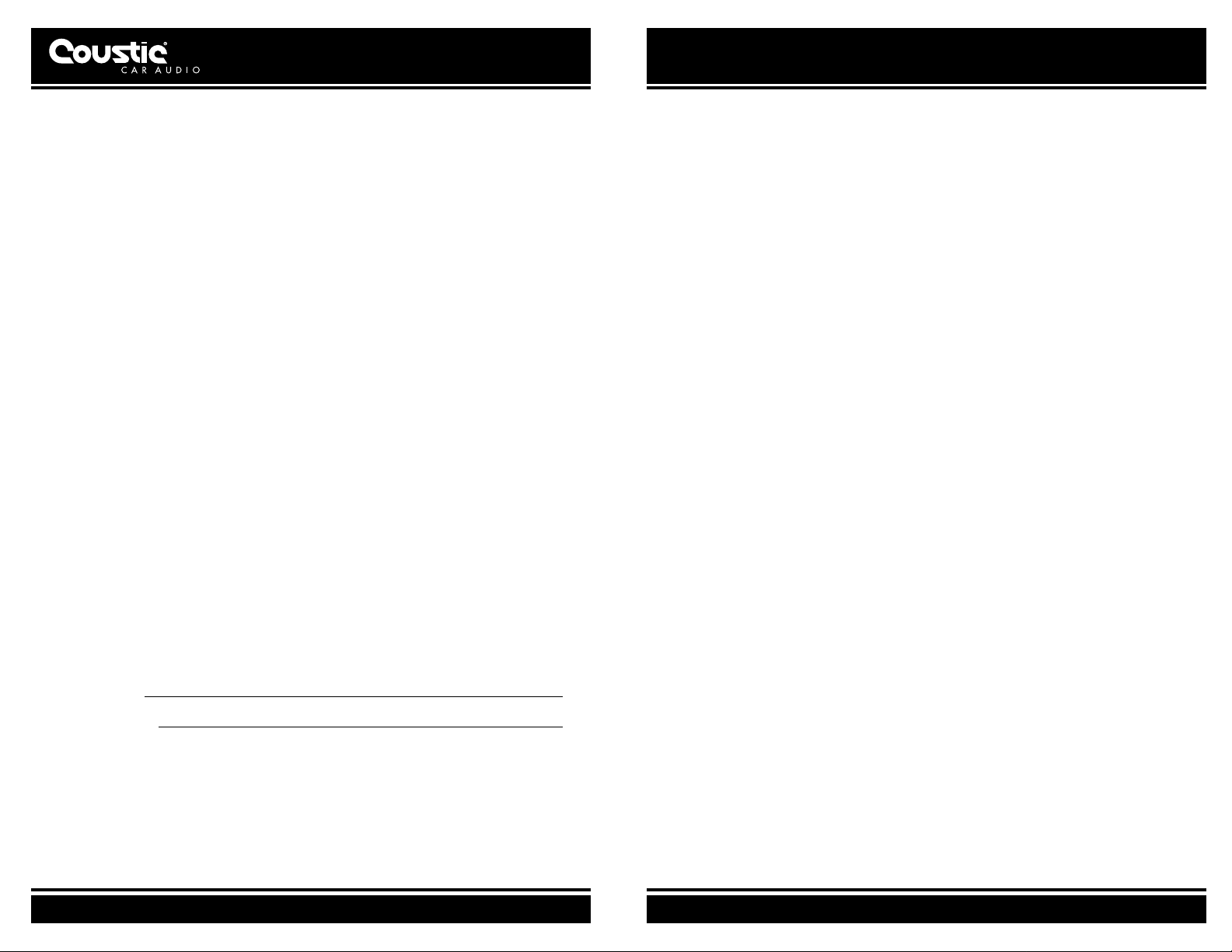
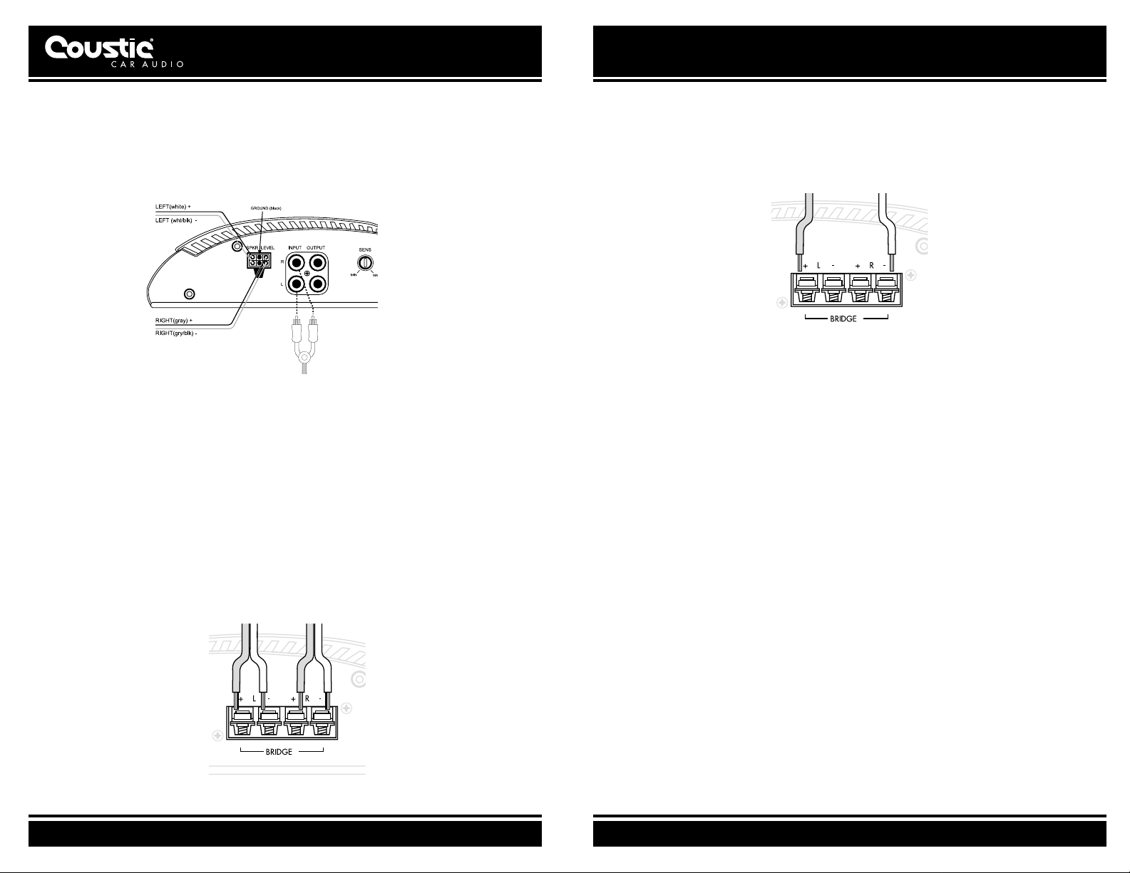
INPUT PANEL
Figure 1: Input Panel Terminals and Controls
1. FILTER MODE SELECT SWITCH (MODE)
"HPF": Slide switch to this position if the amplifier is used as a mid/tweeter amplifier.
"OFF": Slide switch to this position if the amplifier is used as a full-range amplifier.
"LPF": Slide switch to this position if the amplifier is used as a subwoofer amplifier.
2. HIGH-PASS/LOW-PASS FREQUENCY SELECTOR (FREQ)
Select high-pass/low-pass crossover frequency: 80 or 120Hz.
3. INPUT SENSITIVITY LEVEL CONTROL (SENS)
The input sensitivity level can be varied from 5.0 volts to 100 mV depending on the output volt-
age of the source unit (refer to sub-section titled INPUT SENSITIVITY ADJUSTMENT).
4. LINE LEVEL INPUT (RCA)
To be connected to RCA pre-amp outputs from a source unit (i.e., radio, tape deck or CD
player).
5. SPEAKER LEVEL INPUT (SPKR LEVEL)
To be connected to speaker outputs from a source unit (i.e., radio, tape deck or CD player)
when RCA outputs are not available.
6. LINE LEVEL OUTPUT
This output can be used to connect to another amplifier for system expansion.
Note: This line level output is full range.
OUTPUT PANEL
Figure 2: Output Panel Terminals and Indicators
7. POWER AND PROTECT INDICATOR (PWR/PRT)
Green light indicates that the amplifier is "ON".
Red light indicates either a high current, short circuit or DC offset is detected at the speaker
outputs. The amplifier will revert to normal operation once the problem is rectified.
The Red indicator also lights up at a high operating temperature. Under this condition, the
amplifier will automatically shut down. As soon as the temperature falls to a safe level, the
amplifier will automatically resume operation.
8. POWER INPUT TERMINAL (B+)
To be connected to the positive terminal of the vehicle’s battery or other constant +12 V
source.
9. GROUND INPUT TERMINAL (GND)
To be wired to the vehicle’s chassis for ground.
10.REMOTE TURN-ON INPUT TERMINAL (REM)
To be connected to the remote control wire or power antenna lead of the source unit for
remote ON/OFF.
11.FUSE RECEPTACLE
12.LEFT/RIGHT SPEAKER OUTPUT TERMINAL
For connection to the speaker system.
COUSTIC.COM
5
COUSTIC.COM
7
INSTALLATION
By purchasing the 161SE power amplifier, you are already one step closer to experiencing the
purest and most natural sound quality in the automobile environment. To take full advantage of the
potential of this amplifier, before installation, we strongly recommend that you acquaint yourself
with all its available features and then spend some time in designing a system most suitable for
you, consider the components you have now and those that you plan on adding or upgrading in
the future.
The 161SE power amplifier is designed for use with a 12-Volt negative ground system. Installing
this amplifier in a vehicle with a POSITIVE ground system will result in severe damage to the ampli-
fier, other audio components and/or the vehicle’s electrical components. If your vehicle happens to
run on a positive ground system, please consult your Coustic dealer.
Caution: Please follow all the installation recommendations and instructions in this manual. Installing
and/or using the amplifier in methods other than those outlined herein may reduce the perform-
ance capability of the amplifier. Any such installation or usage renders the product
warranty void.
Warning: The battery ground should remain DISCONNECTED at all stages of installation.
LOCATION
Ventilation: The primary deciding factor of amplifier location is heat dissipation. Despite its highly
efficeint heat dissipation design, the amplifier can be crippled by inadequate ventilation. Prolonged
operation at high volumes, combined with inadequate ventilation, may cause the amplifier to over-
heat and trigger the automatic shut down circuit until the temperature returns to a safe level. To
ensure adequate ventilation, the ideal location for the amplifier is a spot away from any heat
source, with at least 2 inches of clearance above and around the unit.
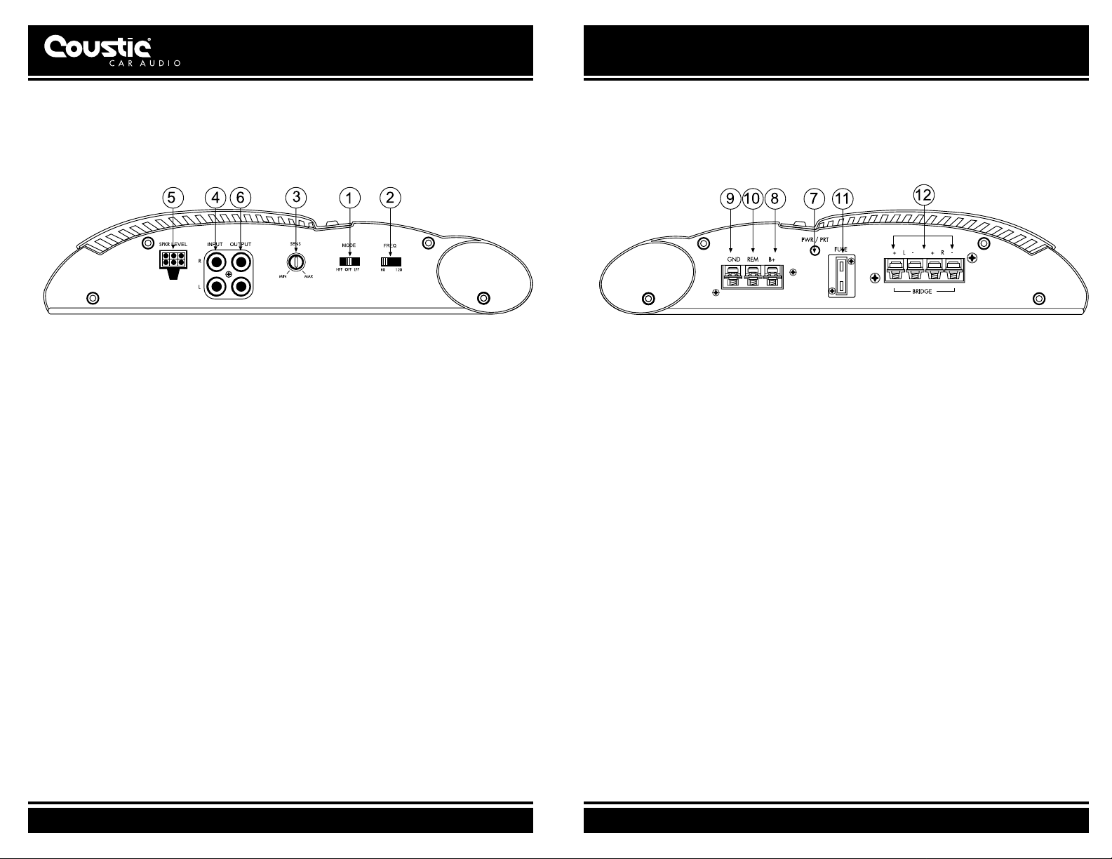
Figure 3: Upright Mount on Horizontal Surface Figure 4: Parallel Mount on Vertical Surface
The amplifier may be mounted upright on a horizontal surface (see Figure 3) or parallel to a verti-
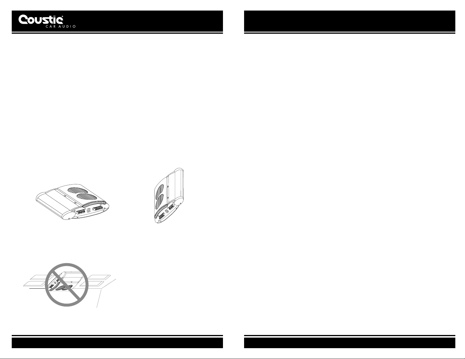
cal surface (see Figure 4). However, the amplifier should never be mounted upside down (see
Figure 5) for the simple reason that the hot air generated by the amplifier would have to go
through the unit internally on its natural upward path (i.e. "feedback" into the unit) and would result
in increased internal temperature. This would speed up the thermal shut down of the amplifier.
Figure 5: Inverted Mount
(Not Recommended)
Vibration: Constant vibration could eventually cause the amplifier to come off from mount, resulting
in stress on wire connections, which, in turn, results in "open" or "short" circuit. For this reason, a
location with minimum vibration and a flat surface for secure and firm mounting should be chosen
for the amplifier.
Moisture: The amplifier should never be exposed to moisture and water.
Taking all the above into consideration, the best mounting position for the amplifier would be the
floor of the trunk or behind the rear seat back.
Once the location of all the components has been determined, plan the best routes for all the nec-
essary wiring, making sure that the wires are easily accessible without dismounting the various
components.
MOUNTING
1. Place the amplifier at the desired location and use it as a template to determine the exact posi-
tion of the mounting holes.
2. Mark the mounting holes with a felt pen.
3. Put the amplifier aside.
4. If the mounting surface is carpeted, cut out small circles of the carpet and padding around the
four mounting holes to expose the metal underneath.
5. Use a center punch to ensure drilling the exact position for the screws. DO NOT BEGIN
DRILLING UNTIL YOU HAVE PUT THE AMPLIFIER ASIDE. USING THE AMPLIFIER AS A
DRILLING GUIDE MAY CAUSE IRREPARABLE DAMAGE TO THE AMPLIFIER.
6. Mount the amplifier with the screws provided.
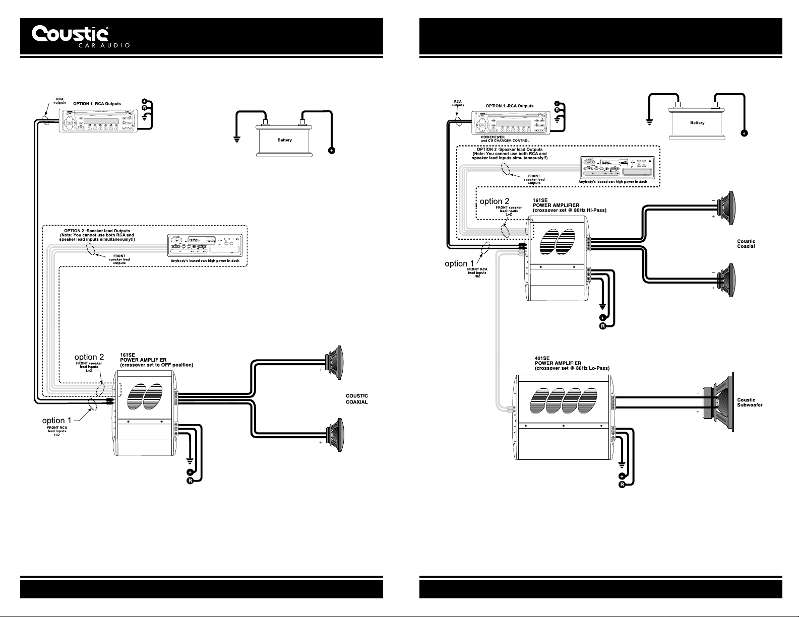
Figure 7.Typical multi-amplifier system
Figure 6.Typical System connection
COUSTIC.COM
9
BI-AMPLIFICATION
A bi-amplified system normally consists of an active crossover and two amplifiers. The active
crossover divides the audio frequency spectrum into two ranges: frequencies below the crossover
point are directed to the amplifier driving the subwoofer(s), while all frequencies above the
crossover point are directed to the amplifier driving the mid-range/tweeters.
COUSTIC.COM
11
INSTALLATION continued
INPUT CONNECTIONS
Connect the RCA input jacks of the Amplifier to the output of the Source Unit (i.e. radio, cassette
player or CD player). If line level output is not available, connect the speaker wires from the
source unit to the Speaker Level input of the amplifier.
Figure 8: High/Low Impedance Inputs
Note: Connect the black ground wire to the source unit ground only if alternator noise is
present.
SPEAKER CONNECTIONS
Connect the Amplifier to the Speakers. Use heavy gauge speaker wires (e.g. 8 - 10 gauge
desirable) for these connections.
FOR STEREO MODE
Note: We recommend a total speaker load of 2, 4 or 8 ohms per channel
1. Connect the left negative ("–") speaker output of the amplifier to the negative terminal of the
left speaker.
2. Connect the left positive ("+") speaker output of the amplifier to the positive terminal of the left
speaker.
3. Connect the right negative ("–") speaker output of the amplifier to the negative terminal of the
right speaker.
4. Connect the right positive ("+") speaker output of the amplifier to the positive terminal of the
right speaker.
Figure 9: Stereo Connection
FOR BRIDGED MONO MODE
Note: For bridged mono mode, we recommend a total load of 4 or 8 ohms.
1. Connect the left positive ("+") speaker output of the amplifier to the positive input terminal of
the speaker.
2. Connect the right negative ("–") speaker output of the amplifier to the negative input terminal of
the speaker.
Figure 10: Bridged Single Woofer Connection
CAUTION: ANY DEVIATION FROM THE ABOVE SPEAKER CONNECTION MAY CAUSE
SERIOUS DAMAGE TO THE AMPLIFIER AND/OR SPEAKERS. PLEASE DOUBLE CHECK THE
CONNECTION BEFORE TURNING THE SYSTEM ON.
 Loading...