


Countyline CLPT85, CLPT36, CLPT20H, CLPT20, CLPT52 User Manual
...
293 Wright Street, Delavan, WI 53115
Phone: 800-535-4950 Fax: 800-526-3757 www.tractorsupply.com
OWNER’S MANUAL
Pre-Charged
Pressure Tanks
MANUAL DEL USUARIO
Tanques de presion precargada
CLPT20H CLPT52
CLPT20 CLPT85
CLPT36 CLPT119
Installation/Operation/Parts |
|
Instalación/Operación/Piezas |
|
For further operating, installation, or |
Para mayor información sobre |
||
maintenance assistance: |
|
el funcionamiento, instalación o |
|
|
|
mantenimiento de la bomba: |
|
Call 800-535-4950 |
|
Llame al 800-535-4950 |
|
English . . . . . . . . . . . . . . . . . |
Pages 2-7 |
Español . . . . . . . . . . . . . |
Páginas 8-13 |
©2017 |
CL491 (Rev. 01/06/17) |

Safety |
2 |
|
|
Important Safety Instructions
SAVE THESE INSTRUCTIONS - This manual contains important instructions that should be followed during installation, operation, and maintenance of the product.  This is the safety alert symbol. When you
 see this symbol on your pump or in this manual, look for one of the following signal words and be alert to the potential for personal injury!
 indicates a hazard which, if not avoided, will result in death or serious injury.


 indicates a hazard which, if not avoided, could result in death or serious injury.
 indicates a hazard which, if not avoided, could result in minor or moderate injury.
NOTICE addresses practices not related to personal injury.
Carefully read and follow all safety instructions in this manual and on pump..
Keep safety labels in good condition. Replace missing or damaged safety labels.
California Proposition 65 Warning


 This product and related accessories contain chemicals known to the State of California to cause cancer, birth defects or other reproductive harm.
1.Read this manual carefully. Failure to follow these Instructions could cause serious bodily injury and/or property damage.
2.Consult installer or licensed plumber for correct relief valve. Install system according to local codes.
3.Always test water from well for purity before using. Check local health department for testing procedure.
4.Before installing or servicing tank, BE SURE pump electric power source is disconnected. Release all water pressure before working on tank or system. Release air pressure before removing cover flange.
5.Install relief valve in pump supply line to tank, as close to tank as possible.
6.BE SURE pump electrical circuit is properly grounded.
7.Remove bleeder orifices, air volume controls or other air charging devices in existing system.
8.DO NOT USE tank as a surge suppressor.


 Risk of explosion.. To prevent possible serious or fatal injury and/or damage to equipment, system pressure must be less than 100 pounds per square inch (PSI) (689kPa) under any circumstances. Failure to follow instruction can result in tank blowup. If system discharge pressure can exceed 100 PSI (689kPa), install a relief valve capable of passing the full pump volume at 100 PSI (689kPa).


 Risk of freezing.. Do not allow pump, tank, or piping system to freeze. Freezing can severely damage equipment and may lead to tank explosion and serious injury. Allowing tank to freeze voids tank warranty.

Warranty |
3 |
|
|
Retain Original Receipt for Warranty Eligibility
Limited Warranty
This Limited Warranty is effective January 1, 2013 and replaces all undated warranties and warranties dated before January 1, 2013.
CountyLine warrants to the original consumer purchaser (“Purchaser” or “You”) that its products are free from defects in material and workmanship for a period of twelve (12) months from the date of the original consumer purchase. If, within twelve (12) months from the original consumer purchase, any such product shall prove to be defective, it shall be repaired or replaced at CountyLine’s option, subject to the terms and conditions set forth herein. Note that this limited warranty applies to manufacturing defects only and not to ordinary wear and tear. All mechanical devices need periodic parts and service to perform well. This limited warranty does not cover repair when normal use has exhausted the life of a part or the equipment.
The original purchase receipt and product warranty information label are required to determine warranty eligibility. Eligibility is based on purchase date of original product – not the date of replacement under warranty. The warranty is limited to repair or replacement of original purchased product only, not replacement product (i.e. one warranty replacement allowed per purchase). Purchaser pays all removal, installation, labor, shipping, and incidental charges.
For parts or troubleshooting assistance, DO NOT return product to your retail store. Contact CountyLine Customer Service at 800-535-4950.
Claims made under this warranty shall be made by returning the product (except sewage pumps, see below) to the retail outlet where it was purchased immediately after the discovery of any alleged defect. CountyLine will subsequently take corrective action as promptly as reasonably possible. No requests for service will be accepted if received more than 30 days after the warranty expires. Warranty is not transferable and does not apply to products used in commercial/rental applications.
Sewage Pumps
DO NOT return a sewage pump (that has been installed) to your retail store. Contact CountyLine Customer Service. Sewage pumps that have seen service and been removed carry a contamination hazard with them.
If your sewage pump has failed:
•Wear rubber gloves when handling the pump;
•For warranty purposes, return the pump’s cord tag and original receipt of purchase to the retail store;
•Dispose of the pump according to local disposal ordinances.
Exceptions to the Twelve (12) Month Limited Warranty
Product |
Warranty Period |
|
|
CL106, CL108 |
90 days |
|
|
CLTS33P, CLSU14 |
2 Years |
|
|
4” Submersible Well Pumps |
3 Years |
|
|
CLVS50C, CLW750, Pressure Tanks |
5 Years |
|
|
General Terms and Conditions; Limitation of Remedies
You must pay all labor and shipping charges necessary to replace product covered by this warranty. This warranty does not apply to the following: (1) acts of God; (2) products which, in CountyLine’s sole judgement, have been subject to negligence, abuse, accident, misapplication, tampering, or alteration; (3) failures due to improper installation, operation, maintenance or storage; (4) atypical or unapproved application, use or service; (5) failures caused by corrosion, rust or other foreign materials in the system, or operation at pressures in excess of recommended maximums.
This warranty sets forth CountyLine’s sole obligation and purchaser’s exclusive remedy for defective products.
COUNTYLINE SHALL NOT BE LIABLE FOR ANY CONSEQUENTIAL, INCIDENTAL, OR CONTINGENT DAMAGES WHATSOEVER.
THE FOREGOING WARRANTIES ARE EXCLUSIVE AND IN LIEU OF ALL OTHER EXPRESS AND IMPLIED WARRANTIES, INCLUDING BUT NOT LIMITED TO THE IMPLIED WARRANTIES OF MERCHANTABILITY AND FITNESS FOR A PARTICULAR PURPOSE. THE FOREGOING WARRANTIES SHALL NOT EXTEND BEYOND THE DURATION PROVIDED HEREIN.
Some states do not allow the exclusion or limitation of incidental or consequential damages or limitations on how long an implied warranty lasts, so the above limitations or exclusions may not apply to You. This warranty gives You specific legal rights and You may also have other rights which vary from state to state.
CountyLine • 293 Wright Street • Delavan, WI U..S..A.. 53115 Phone: 800-535-4950 • Fax: 800-526-3757 • www..tractorsupply..com

Installation |
4 |
|
|
General Information
Tanks listed below are pre-charged, or filled with air at the factory, to 40 pounds per square inch (PSI) (276kPa). When installing tank, set tank pressure according to Chart 1. To do this, bleed air from or add air to tank through valve on top of tank.
NOTICE Always set or check tank pre-charge with NO WATER in tank or water pressure in system. If you have already pumped water
before setting or checking pre-charge pressure, turn pump off. Open faucet until there is no more water pressure. Set pre-charge in tank according to Chart 1, then close faucet and turn pump back on.
NOTICE Replace and tighten air valve cap after pressure is adjusted correctly. Failure to replace air cap may allow loss of air pressure and lead to tank waterlogging and bladder failure.
When Pressure Switch |
Reduce Tank Precharge |
Setting Is: |
(PSI) To: |
|
|
20-40 PSI (138-276 kPa) |
18 (124 kPa) |
|
|
30-50 PSI (207-345 kPa) |
28 (193 kPa) |
|
|
40-60 PSI (276-414 kPa) |
38 (262 kPa) |
|
|
Chart I - Tank Precharge Settings
(The first number on the pressure switch is the pump ‘ON’ setting; the second number is the pump ‘OFF’ setting.)
Pre-charged storage tanks can be connected together to increase the drawdown. Drawdown is the actual amount of usable water available from when the tank is full to when the pump turns on. Installing two tanks of same size will double the drawdown supply, three tanks will triple the drawdown supply, (Figure 1). Locate pressure switch as shown. Tank and pressure switch cannot be more than 10’ (3M) apart.
Tanks
Pressure switch
From well |
|
To service |
|
Figure 1
NOTICE Tank capacity is different than drawdown. Tank capacity is the actual physical volume of the sheet metal that makes up
the tank.
Operating Cycle
A B
C D
WATER
Figure 2 - Tank Operating Cycle
1.Tank nearly empty – air expands filling area above bladder (Figure 2A).
2.Water enters tank – air is compressed above bladder as it fills with water (Figure 2B).
3.Pump-up cycle completed – air compressed to OFF setting of pressure switch (Figure 2C).
4.Water drawn from tank – compressed tank air forces water out of bladder (Figure 2D).
5.Bladder empty – new cycle ready to begin (Figure 2A).
Installation
Connect discharge pipe from pump to a tee. Connect one side of tee to tank flange and the other side of tee to service. Use plastic or steel pipe as required. To prevent leaks, use PTFE pipe thread sealant tape on male threads of all threaded connections to tank.
NOTICE To be sure pipe joints are not crossthreaded and all threads are clean, make connections by hand (without sealer) first. When threads are clean, remove pipe, add PTFE tape, and remake connection. Tighten by hand first; finish with pipe wrench.
When installing an elbow or nipple in the plastic tank flange, tighten it hand tight plus 1-1/2 turns with a pipe wrench. DO NOT OVERTIGHTEN!
Standard Tank Replacement
When replacing standard tank in a water system with pre-charged tank, no bleeder orifices or Air Volume Control (AVC) are required. When sizing a pre-charged tank to replace a standard tank, the tanks should have equivalent drawdowns. For example, model CLPT20 pre-charged tank has a drawdown of 5.8 gallons (22L) and is equivalent to a 42 gallon standard tank that has a drawdown of 4.3 gallons (16.3L).
Installation |
5 |
|
|


 Risk of electric shock and explosion.. Disconnect all power to pump and bleed all pressure from system before working on pump, tank, or piping.
For jet pump installation, remove AVC tube from port in pump body or jet body and plug port (see Figure 3). New pumps come with plug installed.
Figure 3 - Plug AVC Port when installing precharged tank on existing pumps. New pumps come with plug Installed.
NOTICE When working on submersible pumps in wells, be sure safety rope is solidly connected to pump and securely anchored at the well head at all times. Do not drop the pump down the well!
Bleeder Orifices
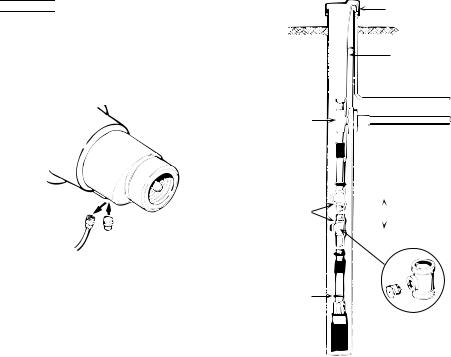
For submersible pump installations, there may be bleeder orifices in the vertical discharge pipe. They must be removed and the tees plugged when a pre-charged tank is installed in the system. To do this, raise the pump and discharge piping enough to bring the bleeder orifices clear of the well. Remove the bleeder orifices from tees and replace with plugs (see
Figure 4). Bleeder orifices may be any of several sizes. Have a supply of 1/2”, 3/4”, and 1” plugs available. Replace pump and reconnect the discharge pipe.
Adjusting Tank Pre-charge
In areas where temperature is high for long periods of time, tank pre-charge pressure may increase. This may reduce tank drawdown (amount of water available per cycle). If this occurs, adjust pre-charge pressure according to
Chart 1.
Flush all air out of piping system and water reservoir portion of pre-charged tank. Adjustment of tank pre-charge is required on new installations, pumps requiring re-priming, and pumps disassembled for service.
Ventilated well cap
Submersible cable
Pitless adaptor
Check valve 

Bleeder orifice |
2 ft. |
|
|
|
|||
and tee |
|
||
(.6m) |
|
||
|
|
|
|
|
|
|
|
Pipe coupling 

Tape cable to pipe
Pump 

Figure 4
Adjust tank precharge as follows:
1.Open faucets furthest from tank and run pump.
2.Run pump until sputtering stops and steady stream of water flows.
3.Open and close faucets repeatedly until all air has been removed.
4.If stream does not become steady, air may be leaking into system; check for leaks in piping on suction side of pump.
NOTICE To prevent waterlogging, check tank air charge annually.
To Check Tank Air Charge
If drawdown decreases significantly, check as follows:
1.To check air charge in tank, shut off electric power to pump, open faucet near tank, and drain completely.
2.At air valve, check tank air pressure with tire gauge. See Chart 1 for correct pressure setting. If needed, adjust tank pressure up or down.
3.Use soap or liquid detergent to check for air leaks around air valve. Continuous bubbling indicates leak. If necessary, release air pressure and install new core in air valve, (same type used for automobile tubeless tires.)
 Loading...