


COUNTRY FLAME TECHNOLOGIES
INSTALLATION, OPERATION AND MAINTENANCE MANUAL
LITTLE RASCAL PELLET FUEL STOVE
FREESTANDING/FIREPLACE INSERT, MODEL LR-01
USA & CANADA TEST: |
TESTED BY: |
ASTM E 1509-03, ULCS627-M90 |
WARNOCK HERSEY |
ULCS628-M92, UL 1482, |
|
Oregon Administrative Rules 814-23-900 thru 909
Country Flame Technologies
A Division of American Products, LLC
900 George Street Marshfield, MO 65706 417-859-0990 phone 417-859-0192 fax
www.countryflame.com
MOBILE HOME APPROVED
FOR YOUR SAFETY
Do not store or use gasoline or other flammables (vapor or liquids) in or around the vicinity of this appliance.
Installation and repair must be performed by a qualified service agency.
Always check with local jurisdiction or code agency before installing
WARNING: If the directions in this manual are not followed exactly, a fire may result causing property damage, personal injury or loss of
© 2004 |
COUNTRY FLAME |
|
|
Version 1.0 |
1 |

LITTLE RASCAL
MODEL LR-01 PELLET FUEL STOVE
TABLE OF CONTENTS
Introduction |
Page 3 |
Safety Notes |
Page 4-6 |
Specifications |
Page 7 |
Operating Instructions |
Page 8-15 |
Description |
Page 8 |
Pre-Operation Notes |
Page 10 |
Intelli-Choice Control Panel |
Page 11 |
Lighting Procedure |
Page 16 |
Shut System Down |
Page 17 |
Maintenance |
Page 18 |
Installation Instructions |
Page 20 |
Precautions |
Page 20 |
Free Standing Unit |
|
Positioning |
Page 21 |
Venting |
Page 22 |
Details |
Page 25 |
Leg & Pedestal Installation |
Page 26 |
Insert Unit |
|
Positioning |
Page 27 |
Venting |
Page 28 |
Details |
Page 30 |
Mobile Home Venting Standards |
Page 31 |
Electrical/Schematic |
Page 32 |
Plates & Tags |
Page 33 |
Warranty |
Page 34 |
LOOK AT THE LABEL ON THE BACK OF YOUR UNIT TO FIND THE SERIAL NUMBER. WRITE IT HERE _______________ IMMEDIATELY.
Failure to do so will make servicing and maintenance questions difficult to answer and could result in needless inconvenience in the future. You will need the serial number of your unit if it requires servicing.
Version 1.0 |
2 |

INTRODUCTION
Congratulations on your purchase of a Country Flame solid fuel heater. Your heater was designed to provide you with durable, reliable performance and ease of operation.
The Country Flame LR-01 has been painstakingly designed with your comfort in mind. On those cool evenings when you’d like a little extra heat in the room, but you don’t want to turn on the furnace, you’ll enjoy the thermal efficiency of the LR-01. Whether you use your unit to heat a single room or several rooms, you’ll appreciate the speed with which your unit can be lit and brought up to temperature.
You’ll feel that you’ve slipped into the homey comforting glow of yesterday as you warm yourself in front of your new heater, with all the comforts of a good, solid wood burning stove, but without the bulk and mess of a conventional heater. While others have to trudge outside to chop wood and gather kindling, you’ll be warming yourself by the fire, fueled by easy to load pelletized solid fuel. On cold winter nights, your LR-01 will become a true friend and you’ll wonder how you ever got along without it.
Features: |
|
*Clean Pelletized Solid Fuel System |
*HOT 15 Tube Exchanger Design |
*Industry Proven Auger System |
*Solid Brass Door & Trim Available |
*Integrated Control System |
*Insert Installation Option |
*Freestanding Pedestal and Queen Ann Leg Options
This is a comprehensive manual – to avoid confusion when installing your stove:
1.Read and familiarize yourself with the Entire Manual and Safety Notes.
2.Follow the Installation Instructions, Precautions, Positioning, Venting, and Details.
3.Follow the Operating Instructions, Lighting, Shutdown and First Time Operation.
Version 1.0 |
3 |

SAFETY NOTES
FOR SAFE OPERATION – THIS MANUAL MUST BE USED FOR INSTALLATION OF STOVE UNIT AND RETAINED BY THE OWNER FOR OPERATION AND MAINTENANCE INFORMATION.
PLEASE READ ALL OF THIS MANUAL AND SAFETY NOTES. The Country Flame LR-01 Pellet Stove is different from conventional wood burning appliances. It is very important that you read and understand all of the instructions before installing and using your Pellet Stove. Follow the procedures and maintenance instructions outlined in this manual exactly. Failure to follow instructions may result in property damage, bodily injury, or even death. It is recommended that you have your unit installed by your authorized Country Flame dealer or at least have them inspect your installation.
1.Because Country Flame has no control over the installation of your unit, Country Flame grants no warranty, implied or written, for the installation or maintenance of your unit and assumes no responsibility for any consequential damage.
2.Fill out the warranty card included with your unit. Send the return portion of the warranty card to Country Flame. Please retain the other portion with this manual.
3.This heater will not operate using natural draft or without a power source for the blowers and fuel feeding system.
4.Never attempt to repair any part of the unit unless following instructions in this manual. Installation and repair should be done by a qualified service technician. Any parts removed for servicing must be replaced prior to operation.
5.Any modifications to the unit, unless authorized by Country Flame, could be dangerous and void the warranty of the unit.
6.This unit must be connected to a grounded standard 110-volt 60hz electrical outlet. NEVER use an adapter cord or cut or remove the grounding prong from the power cord plug.
7.ALWAYS wait until the unit is cooled and disconnect power before performing any maintenance or cleaning procedures.
8.NEVER place combustible objects on or near your heater.
9.NEVER allow children near heater during operation, and do not allow anyone to operate the unit who is unfamiliar with these instructions.
10.Children and adults should be alerted to the hazards of high surface temperature and should stay away to avoid burns or clothing ignition.
11.Young children should be carefully supervised when they are in the same room as the heater.
Version 1.0 |
4 |

12.NEVER connect this unit to a chimney flue serving another appliance.
13.ALWAYS follow the lighting instructions in this manual; short cuts of any kind can be dangerous.
14.Check your local building codes and consult your insurance company before installing your unit.
15.Due to high temperatures, the pellet stove should be located out of traffic and away from furniture and draperies.
16.Clothing or other flammable material should not be placed on or near the room heater.
17.When disposing of ash accumulations from your unit, always place them in a metal container with a tight fitting lid. The closed container must be placed on a noncombustible surface well away from all combustible materials, pending final disposal. The ashes should be retained in the closed container until all cinders have thoroughly cooled.
18.Any safety screen or guard removed for servicing a room heater must be replaced prior to operating the room heater.
19.Your unit is designed and approved for burning of pelletized biomass fuel, which meets or exceeds APFI standards only. Burning of solid fuel in other than pellet form is not permitted. Failure to comply with this restriction will void all warranties and the safety listing of the unit. Poor quality fuel will directly (and adversely) affect efficiency and cleanliness of your unit’s operation. Your Country Flame dealer can help you make the proper fuel choice for your area.
20.NEVER use gasoline, gasoline-type lantern fuel, kerosene, charcoal lighter fluid or similar liquids to start or “freshen up” fire in this heater. Do not store or use gasoline or other flammable vapors and liquids in the vicinity of this or any other appliance.
21.INSTALL a smoke detector within the proximity of your pellet stove.
22.NEVER put foreign objects in the hopper. NEVER burn trash or unapproved material in your LR-01.
23.NEVER block free airflow through open vents.
24.The exhaust system should be checked twice a year (minimum) for any buildup of soot or creosote.
Version 1.0 |
5 |

25.This unit’s exhaust system works with a negative combustion chamber pressure and a low positive flue pipe pressure. It is very important that the exhaust system be
properly installed and air tight. The flue pipe joints should be sealed. Use high temperature RTV (5000F) (2600C) silicone sealant or aluminum flue tape and secured each joint with at least (3) sheet metal screws. Improperly installed stove flues are the major cause of home fires.
26.When installed in a mobile home, a pellet stove must be grounded to the steel chassis of the mobile home and bolted to the floor in compliance with and according to H.U.D. requirements.
27.SOOT AND FLYASH: The products of combustion will contain small particles of flyash. The flyash will collect in the exhaust venting system and restrict the flow of the flue gases. Incomplete combustion, such as occurs during start-up, shut down, or incorrect operation of the room heater will lead to some soot formation which will collect in the exhaust venting system. The exhaust venting system should be inspected at least once every year to determine if cleaning is necessary.
Version 1.0 |
6 |

SPECIFICATIONS |
|
|
|
|
FUEL TYPE: |
A.P.F.I. residential fuel: |
|
|
|
|
Heat Content: 8200 BTU/lb. min. |
|
|
|
|
Bulk Density: 40 lb. /cubic ft. min. |
|
|
|
|
Moisture Content: 8% max |
|
|
|
|
Ash Content: 1% max |
|
|
|
|
Size: |
¼” to 3/8” diameter |
|
|
|
|
1.5” long max |
|
|
|
Fines: 1% max through 1/8th screen |
|
|
|
HOPPER SIZE: |
55# Hopper Capacity |
|
|
|
FLUE SIZE: |
3” or 4” |
|
|
|
TYPE: |
PL double wall vent with stainless steel inner liner |
|||
AIR INLET: |
1 ½” Sch 40 Black Iron Pipe |
|
|
|
AUGER TYPE: |
Tumac 2 ¼ Auger Pellet Feed System |
|
|
|
CONTROLS: |
Integrated Feed Rate/Blower Speed Controls |
|
|
|
ELECTRICAL: |
120 Volts, 2.4 Amp, 60 Hz |
|
|
|
MEASUREMENTS: |
UNIT BODY HEIGHT |
22 |
¾” |
|
|
|
HEIGHT ON PEDESTAL |
32 |
¾” |
|
|
HEIGHT ON LEGS |
31 |
1/4” |
|
|
UNIT WIDTH |
26” |
|
|
|
UNIT DEPTH |
19 |
3/4” |
|
|
SHROUD HEIGHT |
29 |
7/8” |
|
|
SHROUD WIDTH |
45 |
7/8” |
CLEARANCES: |
|
SIDES |
1” |
|
|
|
BACK |
2” |
|
|
|
TOP TO COMBUSTIBLE |
3” |
|
|
|
TOP TO CEILING |
3” |
|
*Combustible Flooring must be covered with non-combustible material extending 6” (150 mm) from front of unit and 8” (205 mm) from unit on each side. The floor protection on the sides of the stove only has to extend to the vertical sidewall(s) if the clearances are less than 8”.
Version 1.0 |
7 |

DESCRIPTION
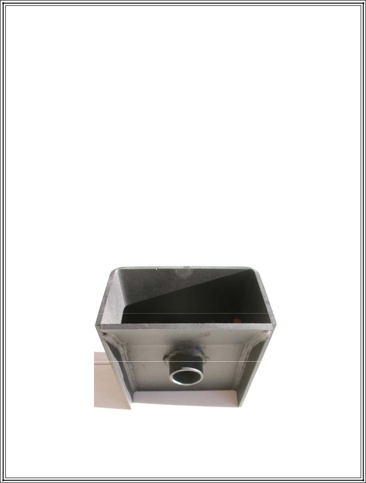
The LR-01 Pellet Stove is designed to sit on a pedestal or legs as a freestanding unit or can be installed as in insert with the optional shroud and split lid. The basic stove unit without shroud or pedestal measures 22 3/4” high by 26” wide and 19 3/4” deep. Centered above the firebox glass front door is a louvered vent through which room convection air is passed.
The right side of the unit has a rheostat control knob to vary the speed of the room air blower. The left side of the unit has a control panel for the integrated “Intelli-Choice” control board. The controls include 5 heat settings, an ON/OFF switch and lights to indicate proper operation. On the back of the unit are located a 3” tube for installation of outlet vent pipe and a hole for installation of a 1 ½” inlet air tube. The top of the unit lifts up for easy loading of fuel. An optional two piece lid is available if the Little Rascal is to be used as an fireplace insert.
1.The Country Flame LR-01 is remarkably simple and safe in its operation. From a relatively small firebox over 40,000 BTU’s per hour can be produced.
2.The fuel (APFI approved) is loaded into the hopper. After the fire has been lit (see lighting instructions) an angled drive auger delivers fuel, a few pellets at a time, into the firepot at a controlled rate. The combustion blower delivers directed air input, creating a vigorous, efficient burn. The hot exhaust gases are drawn through a 14-tube heat exchanger, which extracts heat from the gases as they are discharged to the exhaust pipe.
3.A second blower circulates room air through the heat exchanger, pushing warm air into the room from the tubes located just above the door. The room air blower is intended to run continuously and can be easily controlled to maintain a uniform temperature.
4.The Pellet Stove will deliver a constant amount of heat, which can be varied by setting the fuel control knob. Besides initial lighting of the unit, the only regular attention needed will be to fill the 55# hopper with fuel; inspection of the firepot for “clinkering” (see operating instructions) and removal of ash buildup as required.
AIR DAMPER ADJUSTMENTS
Each LR-01 is shipped with an air damper adjustment. The air damper control is located on the front of the pellet stove below the hearth lip located directly centered on the front door. As site specific operating conditions require, such as fuel, altitude, and customer usage preferences require, there will be a requirement to adjust the air damper for more or less combustion air to the unit. To vary the air, the air damper control is slid in (less air) and out (more air.)
Version 1.0 |
8 |
1.Conditions that warrant more combustion air are: Hardwood pellets
Higher altitudes
Increased heat settings (3- 5)
2.Conditions that warrant less air:
Softwood pellets
Low altitudes
Lower heat settings (2-3)
3. Conditions that warrant even less air: Softwood pellets
Low altitudes
Lower heat settings (1-2)
Things to watch for:
TOO LITTLE AIR
•Extremely lazy flame
•Extremely black and dirty conditions in firebox
•When extended burn on High Settings, too many pellets in firepot
TOO MUCH AIR
•Flame is aggressive but as time progresses, the flame is barely visible
•Fire disappears in burn pot, shown below, or goes out on low settings
Note: Once you have determined the correct air usage for the heat setting and local site conditions, the air damper control will not need to be adjusted as often. Remember, any change in site specific conditions will require an adjustment of the air damper.
Version 1.0 |
9 |

PRE-OPERATION NOTES
1.Thoroughly read and understand this manual. Pay particular attention to the maintenance and safety sections of this manual. Failure to inspect the stove and understand these instructions may cause unsatisfactory performance.
2.Check to see that the intake and exhaust vents are properly tight and correctly installed.
3.Remove protective materials such as plastic coverings, plastic bags, and other material shipped with the stove.
4.Insure that the stove is connected to a code approved 120 volt AC power source. Ensure that the power provided is stable and not varying. If necessary, include a cost-effective UPS (power source) between the stove and house power to minimize any problems with the stove.
5.Open the hopper lid and inspect the hopper before filling with fuel. ENSURE no foreign objects are left in hopper before loading it with approved pellet fuel.
6.The first time the Country Flame pellet stove is fired up, a odor or smoke may emanate from the pellet stove. This is normal and should not last very long. Once the unit is “broken in” (after that first firing) no future odors or smoke should appear.
7.Fuel should conform to A.P.F.I. standards (see page 7).
Version 1.0 |
10 |
IGNITION/START-UP PROCEDURE
Country Flame Technologies introduced its exclusive control board technology in 2001. This control board technology was introduced across all lines of Country Flame’s pellet and corn stove products. Country Flame continues to demonstrate leadership in bringing new products to market. Country Flame developed its own control board technology in order to bring reliable, supportable, and sustainable biomass-fueled products to market throughout the 21st Century.
Country Flame’s control board design goal was simple:
PROVIDE THE LATEST CONTROL METHODOLOGY TO ENSURE MAXIMUM BURN
EFFICIENCY WHILE AUTOMATICALLY CONTROLLING AS MANY ENVIORNMENTAL AND
SYSTEM VARIALBLES IN ORDER TO ENSURE CUSTOMER SATISFACTION WITH THE
PRODUCT WHILE GAINING CONFIDENCE IN THE PRODUCTS ABILITY TO OPERATE
WITH LIMITED CONSUMER EFFORT.
Country Flame’s control board technology is defined as an “open system.” This means that Country Flame will seek to provide the most advanced controls methodology in the coming years while maintaining the look and feel that dealers and customers come to know and expect. This means that a purchase of today’s Country Flame product allows a customer to upgrade to newer and more advanced technology, as it becomes available while minimizing cost. Country Flame is committed to ensuring its customer base will remain a life long family member once the initial purchase of product is complete. Country Flame’s goal is to ensure a service technician can diagnose and repair any product problem in less than 30 minutes from arrival to departure of a customer’s home. The service technician will have to demonstrate an understanding of control methodology, sensors, basic electric theory, and system operation in order to assist in achieving these Country Flame goals.
The following block diagram demonstrates the basic theory behind today’s Country Flame control board technology:
|
VACUUM |
OVERTEMP |
FUEL |
COMBUSTION |
THERMOSTAT |
|
(Optional) |
||||
|
SENSOR |
SENSOR |
CONTROL |
AIR CONTROL |
|
|
|
|
CONTROL BOARD |
|
|
INPUT VOLTAGE |
Fuse |
|
ON/OFF SWITCH |
|
|
120 Volts AC 60 Hz |
6 – 9 |
|
TEMPERATURE CONTROL |
|
|
15-Ampere Circuit |
|
|
|||
Amperes |
|
|
|||
|
POWER/FUEL/IGNITER/ INDICATORS |
||||
|
|
||||
|
|
|
|
|
STOVE |
|
EXHAUST |
ROOM AIR |
ROOM AIR |
IGNITER |
|
|
TEMPERATURE |
TEMPERATURE |
CONTROL |
||
|
SENSOR |
SENSOR |
|
|
|
The basic block diagram shows the input and output components to the control board. The failure of any of these items to work properly will cause a malfunction in the system. Further information on each function is provided in the tables below.
Version 1.0 |
11 |

|
|
|
|
|
Input Voltage |
Alternating Current (AC) Input provided by the local power |
|
|
company. This source of energy must provide a 120 Volt input |
|
|
|
signal with a frequency of 60 Hertz and a maximum branch |
|
|
|
|
current capacity of 15 Amperes. If other devices are connected to |
|
|
|
the branch, interference or over current may cause circuit breaker |
|
|
|
to trip. |
|
|
Fuse |
The AC fuse should be rated between 6 and 9 amperes. The |
|
|
|
recommended fuse is a Little Fuse Model _______. |
|
|
Vacuum Sensor |
Ensures that no blockage of the combustion input or combustion |
|
|
|
exhaust air occurs. If the vacuum sensor does not operate |
|
|
|
properly, the Control Board will not allow the stove to operate. |
|
|
Exhaust Temperature Sensor |
Presently, this sensor is a snap disk operating at 110o F +/- 20o F. |
|
|
|
This sensor ensures proper exhaust temperature has been reached |
|
|
|
and that a fire is present in the burn pot before the control system |
|
|
|
begins the burn cycle. |
|
|
Room Air Temperature Sensor |
Presently, this sensor is a snap disk operating at 110o F +/- 20o F. |
|
|
|
This sensor ensures that a proper amount of heat is available at the |
|
|
|
heat exchanger before the room fan is allowed to operate. If the |
|
|
|
sensor allows the fan to come on to early, the combustion |
|
|
|
chambers temperature could drop to the point that self-combustion |
|
|
|
(ignition temperatures) cannot be maintained. |
|
|
Overtemp Sensor |
Presently, this sensor is a snap disk operating at 250o F +/- 20o F. |
|
|
|
The purpose of this sensor is to shut the entire system down in the |
|
|
|
event the firebox causes an overheat condition. |
|
|
Fuel Control |
The fuel control is a signal provided from the Control Board to the |
|
|
|
Auger Feed Motor. The Control Board controls the amount of |
|
|
|
time that the Auger Feed Motor is on and thereby controls the |
|
|
|
amount of fuel fed to the fire pot. |
|
|
Room Air Control |
The room air control is a signal provided from the Control Board |
|
|
|
to the Room Air Fan. The Control Board controls the phase angle |
|
|
|
and thereby the amount and time an AC voltage is applied to the |
|
|
|
Room Air Fan. This signal controls the speed of the room air |
|
|
|
passing over the heat exchanger tubes and the amount of heat |
|
|
|
delivered to the living space. |
|
|
Combustion Air Control |
The combustion air control is a signal provided from the Control |
|
|
|
Board to the Combustion Fan. The Control Board controls the |
|
|
|
phase angle and thereby the amount and time an AC voltage is |
|
|
|
applied to the Combustion Air Fan. This signal controls the speed |
|
|
|
of the combustion air passing through the burn pot for the different |
|
|
|
heat settings |
|
|
|
An AC heating element used to provide initial heat to the pellet |
|
|
|
combustion process. Once the Control Board senses combustion, |
|
|
|
the Igniter is shut off to conserve energy usage. |
|
|
|
|
|
|
Thermostat (optional) |
A thermostat input is provided on the back of each Country Flame |
|
|
|
product. The Control Board has individual personality modules |
|
|
|
that allow for stand-alone, semi automatic, or fully automatic |
|
|
|
thermostat operation. |
|
|
|
|
|
Version 1.0 |
12 |
 Loading...