

Page 1
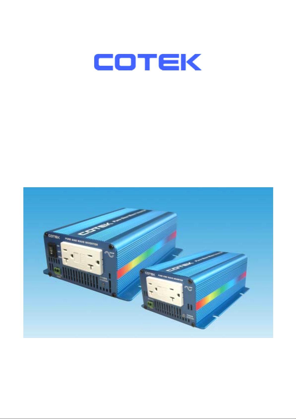
S150,S300 Series
Pure Sine Wave Inverter
User’s Manual
Page 2

List of contents
1. Important Safety Instructions……………………………………………… 3
1-1 General Safety Precautions…………………………………………… 3
1-2 Precautions When Working With Batteries………………………….. 3
2. Features………………………………………………………………………... 4
2-1 Electrical Performance 150W….……………………………………… 4
2-2 Electrical Performance 300W….……………………………………… 5
2-3 Mechanical Drawings 150W.………………………………………….. 6
2-4 Mechanical Drawings 300W.………………………………………….. 7
3. Introduction…………………………………………………………………… 8
3-1 Front Panel Operations………………………………………………... 8
3-2 Rear Panel Operations………………………………………………… 8
3-3 AC Safety Grounding…………..………………………………………. 9
3-4 Installation………………………..……………………………………... 10
3-5 DC Input (Outlet sockets available)……….………………………….. 11
3-6 AC output (Outlet sockets available)…………………………………. 11
4. Troubleshooting guide……………………………………………………… 12
5. Maintenance…………………………………………………………………… 13
6. Warranty……………………………………………………………………….. 13
©Copyright :This manual is the copyright of COTEK Electronic lnd. Co., Ltd. And may not be reproduced or copied
without the express permission of the owner.
2
Page 3

1. Important Safety Instructions
WARNING!
Before you install and use Your Inverter, to read and save
these safety instructions.
1-1. General Safety Precautions
1-1-1. Do not expose the Inverter to rain, snow, spray, bilge or dust.
To reduce risk of hazard, do not obstruct the ventilation
openings. Do not install the Inverter in a zero-clearance
compartment. Overheating may result.
1-1-2. To avoid a risk of fire and electric shock. Make sure that existing
wiring is in good electrical conditions and the size is not undersized.
Do not operate the Inverter with damaged or substandard wiring.
1-1-3. This equipment contains components which can produce arcs or
sparks. To prevent fire or explosion, do not install in compartments
containing batteries or Flammable materials or in locations which
require ignition protected equipment. This includes any space
containing gasoline-powered machinery, fuel tanks, or joints, fittings,
or other connection between components of the fuel system.
1-2. Precautions When Working with Batteries
1-2-1. If battery acid contacts skin or clothing, wash immediately with soap
and water. If acid enters eye, immediately flood eye with running
cold water for at least 20 minutes and get medical attention
immediately.
1-2-2. Never smoke or allow a spark or flame in vicinity of battery or Engine.
1-2-3. Do not drop a metal tool on the battery. The resulting spark or
short-circuit on the battery of other electrical part may cause an
explosion.
1-2-4. Remove personal metal items such as rings, bracelets, necklaces,
and watches when working with a lead-acid battery.
A lead-acid battery can produces a short-circuit current high enough
to weld a ring or the like to metal, causing severe burns.
3
Page 4
2.Features
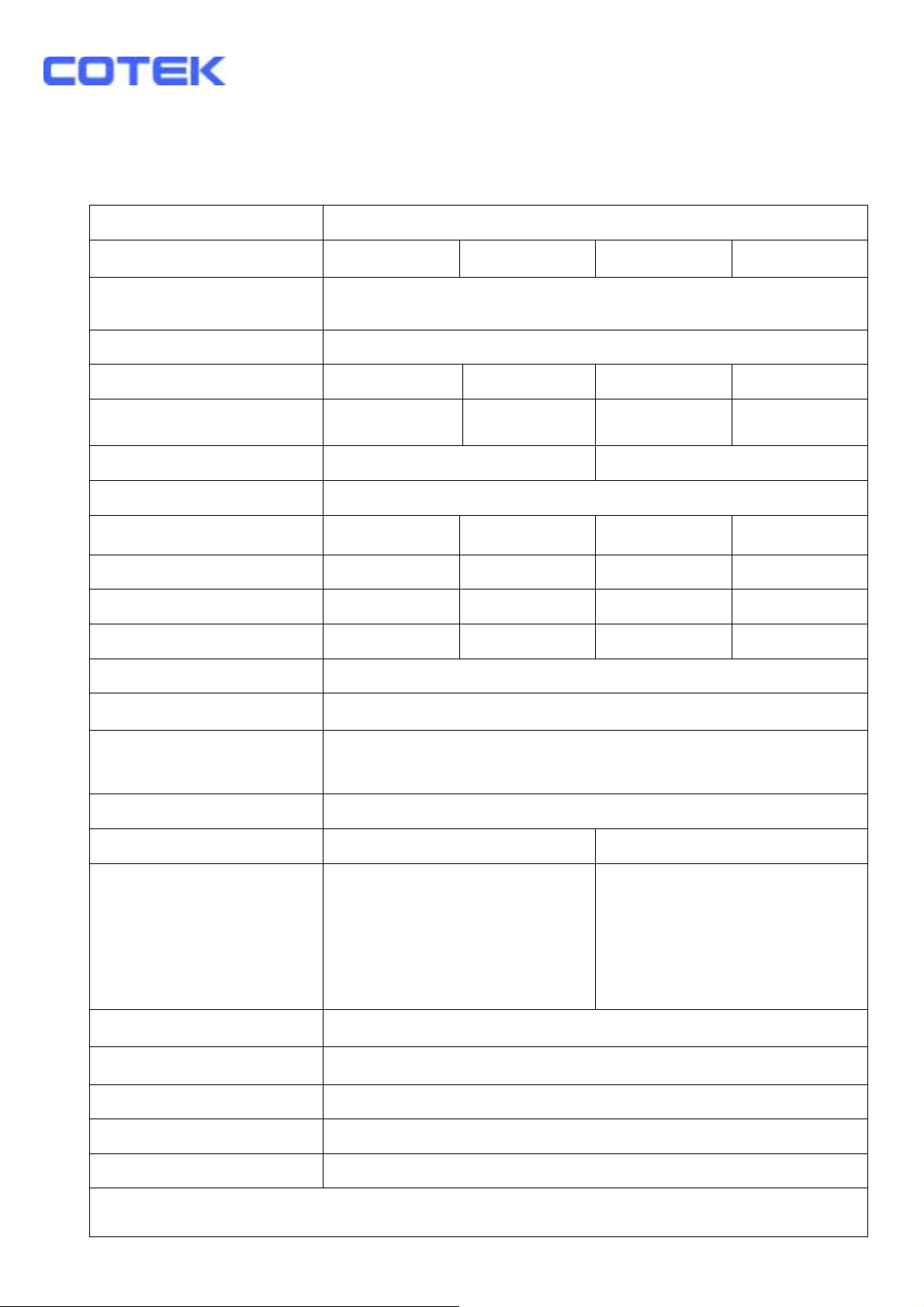
2-1. Electrical Performance 150W
Specification Model No.
Item S150-112 S150-124 S150-212 S150-224
Continuous Output
Power
Surge Rating 200W
Input voltage 12V 24V 12V 24V
Input Voltage Range 10.5 – 15.0 21.0 – 30.0 10.5 – 15.0 21.0 – 30.0
Output Voltage
Frequency 50 / 60Hz ± 0.3%
Efficiency (Peak Load) 91% 92% 90% 93%
Efficiency (Max. / Avg.) 86% 87% 85% 88%
Efficiency (Full Load) 72% 79% 72% 80%
No Load Current Draw 0.18A 0.15A 0.22A 0.16A
Output Waveform Pure Sine Wave ( THD < 4% )
Power Factor Allowed
110 VAC ±5% 230 VAC ±5%
cosθ-90° ~ cosθ+90°
150W
Protection
Remote Control Yes, On/Off controlled by external switch
Safety* Meet UL458 Meet EN60950
EMC** Meet FCC Class B
Operating Temperature
Storage Temperature
Fan Cooling Thermostatically controlled
Dimensions (L x W x H) 200 x 132 x 72 mm / 7.87 x 5.20 x 2.83 inch
Weight 2.7 kgs. / 5.4 Lbs.
Overload, Short Circuit, Reverse Polarity (Fuse),
Over / Under Input Voltage, Over Temperature.
Meet EN50081-1:1992
Meet EN50082-1:1992
Meet EN55022B:1994
Meet EN61000-4-2:1995
Meet EN61000-4-3:1996
Meet ENV50204:1995
0 – 40 ℃
-30℃ to 70℃
*110V mode design meets UL 458 & FCC Class B. **230V model design meets CE & “e “ Mark. (Currently, all
applied projects are pending)
4
Page 5
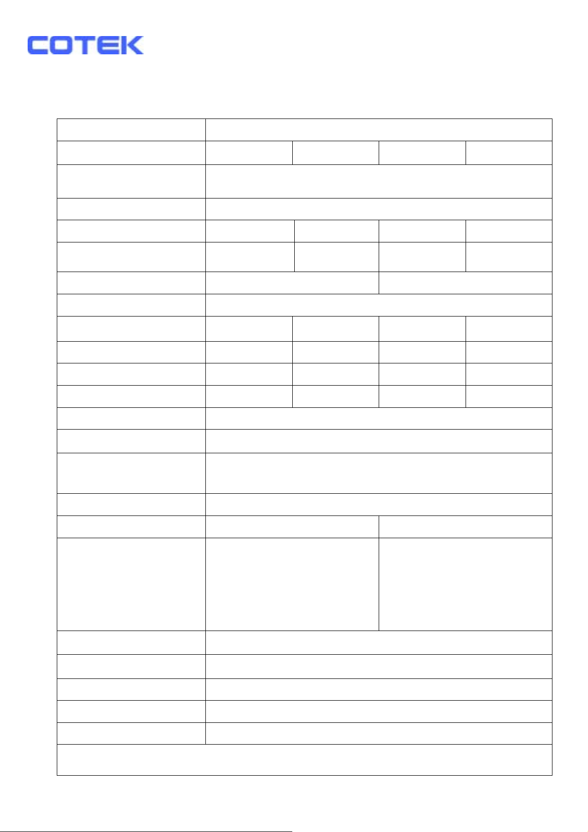
2-2. Electrical Performance 300W
Specification Model No.
Item S300-112 S300-124 S300-212 S300-224
Continuous Output
Power
Surge Rating 400W
Input voltage 12V 24V 12V 24V
Input Voltage Range 10.5 – 15.0 21.0 – 30.0 10.5 – 15.0 21.0 – 30.0
Output Voltage
Frequency 50 / 60Hz ± 0.3%
Efficiency (Peak Load) 92% 93% 91% 94%
Efficiency (Max. / Avg.) 87% 88% 86% 89%
Efficiency (Full Load) 72% 78% 72% 80%
No Load Current Draw 0.26A 0.23A 0.23A 0.15A
Output Waveform Pure Sine Wave ( THD < 4% )
Power Factor Allowed
110 VAC ±5% 230 VAC ±5%
cosθ-90° ~ cosθ+90°
300W
Protection
Remote Control Yes, On/Off controlled by external switch
Safety* Meet UL458 Meet EN60950
EMC** Meet FCC Class B
Operating Temperature
Storage Temperature
Fan Cooling Thermostatically controlled
Dimensions (L x W x H) 237 x 155 x 72 mm / 9.33 x 6.10 x 2.83 inch
Weight 3.5 kgs. / 7.7 Lbs.
Overload, Short Circuit, Reverse Polarity (Fuse),
Over / Under Input Voltage, Over Temperature.
Meet EN50081-1:1992
Meet EN50082-1:1992
Meet EN55022B:1994
Meet EN61000-4-2:1995
Meet EN61000-4-3:1996
Meet ENV50204:1995
0 – 40 ℃
-30℃ to 70℃
*110V mode design meets UL 458 & FCC Class B. **230V model design meets CE & “e “ Mark. (Currently, all
applied projects are pending)
5
Page 6
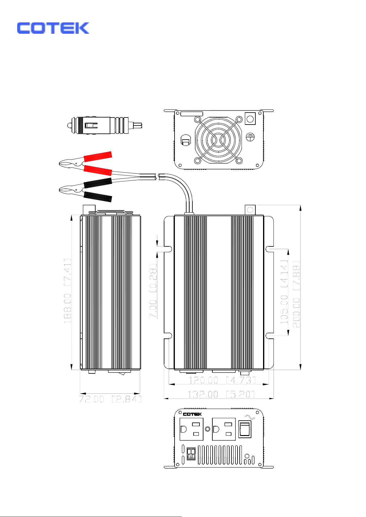
2-3. Mechanical Drawing
150W
GROUND
CHASSIS
DC INPUT
REMOTE
PORT
PURE SINE WAVE INVERTER
AC OUTPUT
I
0
POWER
STATUS
150W
ON
OFF
REMO.
6
Page 7
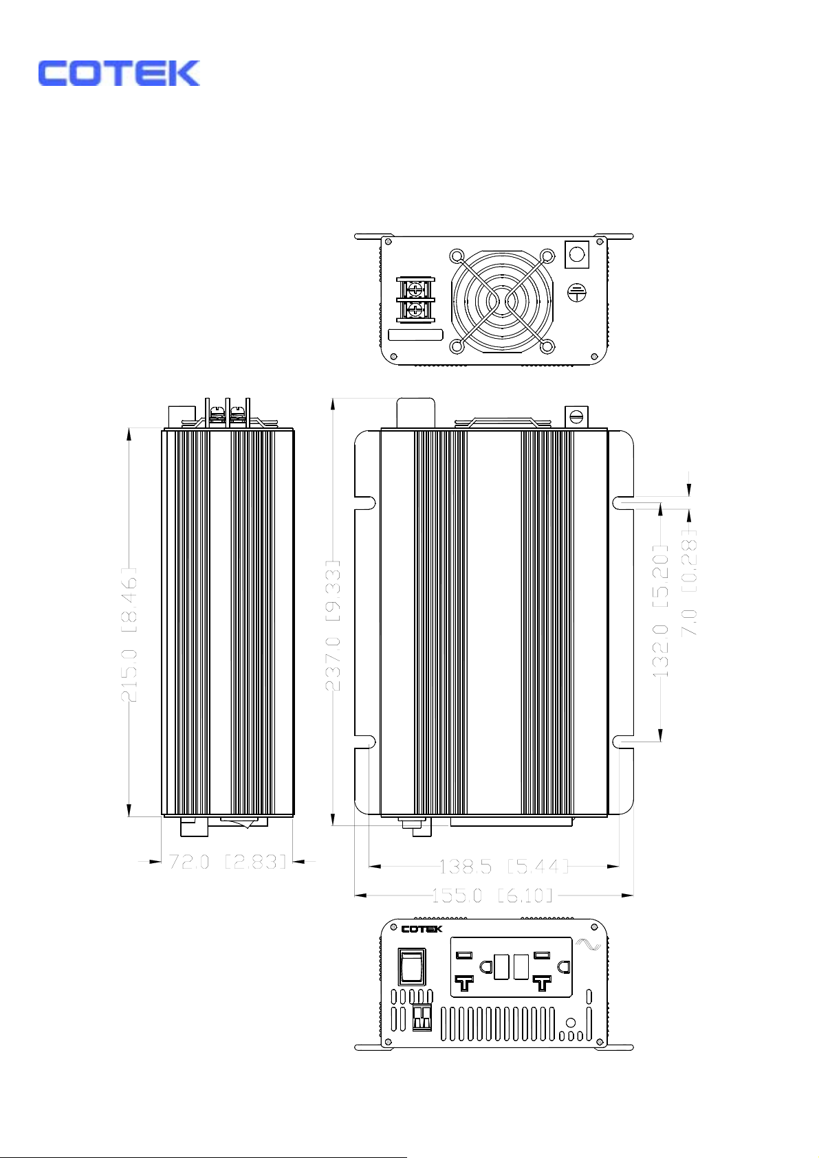
2-4. Mechanical Drawing
300W
WILL DAMAGE UNIT
REVERSE POLARITY
WARNING:
GROUND
POS+
NEG -
DC INPUT
CHASSIS
I
0
REMOTE
PORT
PURE SINE WAVE INVERTER
ON
OFF
REMO.
AC OUTPUT
POWER
STATUS
300W
7
Page 8
3. Introduction
This series models are the most, reliable, multi protections, compact size, pure sine wave inverters that used in wide range of applications including Mobile, Office equipments, Home entertainments, electronics hold equipments.
To get the most out of the power inverter, it must be installed and used
properly. Please read the instructions in this manual before installation
and operation this model.
3-1. Front Panel Operations:
3-1-1. ON / OFF/ REMOTE switch:
Leave the Power ON / OFF / REMOTE switch in the OFF position during installation.
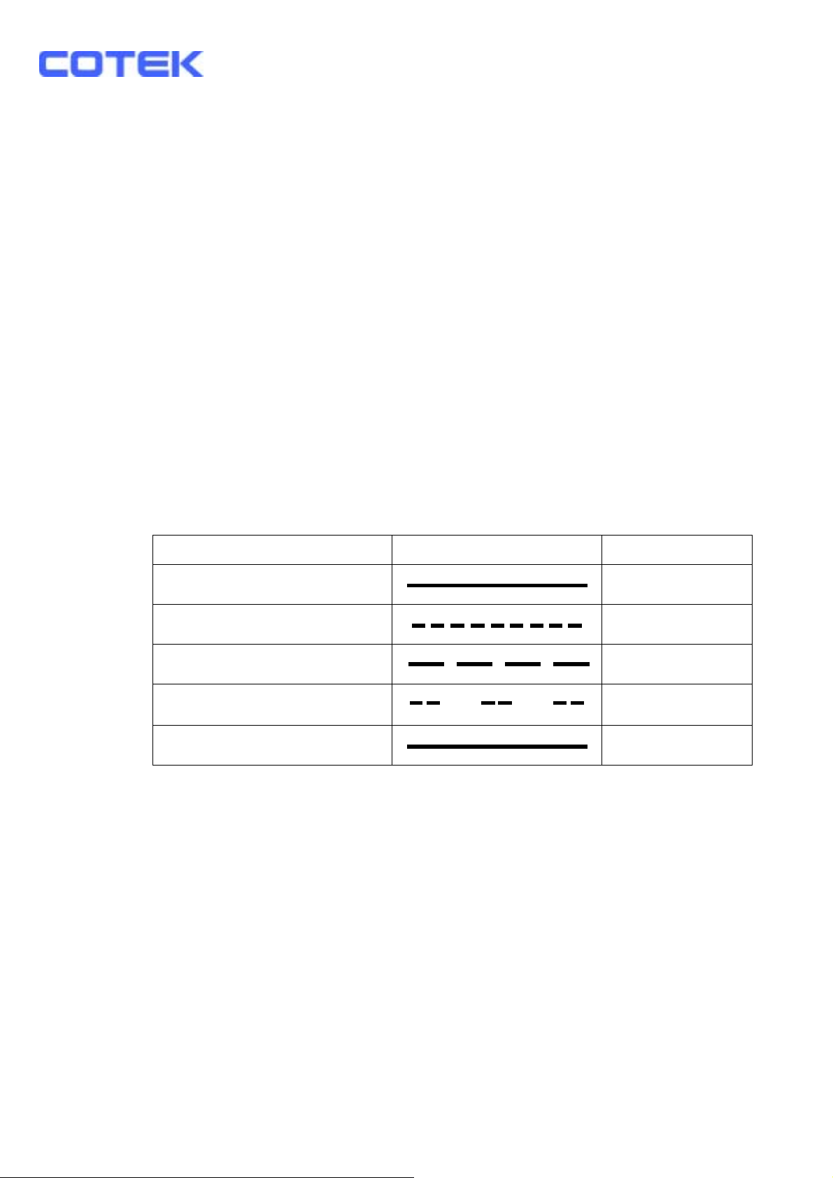
3-1-2 LED display indicates Power Status
LED Conditions Status
Solid Green
Blinked Red fast
Blinked Red slowly
Blinked Red intermittently
Solid Red
3-1-3. Remote Port: Placing 0.75mm2 and Screw type cable between
remote port and panel.
3-2. Rear Panel Operations
3-2-1. Ventilation window: Do not obstruct, allow at least 3 inch of
clearance for airflow.
AC Power OK
OVP
UVP
OTP
OLP
3-2-2. Input terminals: Connect 12V / 24V batteries or other 12V / 24V power
sources. 【+】is positive,【-】is negative.
Reverse polarity connection will blow internal fuse
and may damage inverter permanently.
3-2-3. Using # 8 AWG wire to connects Chassis ground with Vehicle Chassis.
8
Page 9
WARNING!
Do not connect the 12V model to a 24V battery,
the unit will be destroyed immediately.
Operation of the inverter without a proper ground
connection may result an electrical safety hazard.
Damage caused by reversed polarity is not covered by
the warranty. Make sure the power switch is in the
OFF position before connecting the battery.
3-3. AC Safety Grounding:
During the AC wiring installation, AC input and output ground wires are
connected to the inverter. The AC input ground wire must connect to the
incoming ground of your AC utility source.
The AC output ground wire should go to the grounding point for your loads
( for example, a distribution panel ground bus ).
3-3-1. Neutral Grounding (GFCI’S):
110V models:The neutral conductor of the AC output circuit of the
Inverter is automatically connected to the safety ground during inverter
operation. This conforms to National Electrical Code requirements
that separately derived AC sources (such as inverter and generators)
have their neutral conductors tied to ground in the same way that the
neutral conductor from the utility is tied to ground at the AC breaker
panel. For models configured with a transfer relay, while AC utility
power is presenting and the Inverter is in bypass mode, this connection
(neutral of the Inverter’s AC output to input safety ground) is not present
so that the utility neutral is only connected to ground at your breaker
panel, as required. Cotek has tested the following GFCI – protected
20A receptacles and found that they functioned properly when
connected to the output of the Inverter
9
Page 10
3-4. Installation
Before connect your applications to the inverter, always c heck the power draw
of your appliances. The inverter is affordable to supply surge power for a
short time so as to start up the electrical equipments such as motor, pumps…
that need more power while starting up.
When all the above requirements are checked OK and satisfied and all
connections are made, it’s the time to turn on your inverter by pushing the
power switch to the ‘ I ’ position. The sine wave shaped output voltage
gently rises from AC outlet.
WARNING!
Never connect the inverter’ output to the AC distribution
grid, such as your household AC wall outlet.
It will damage the Inverter.
When the inverter is not supplying power to an application for a longer time,
it’s recommended to turn off the inverter to save your batteries since it still
draws a small amount of current in the “ no load ” condition.
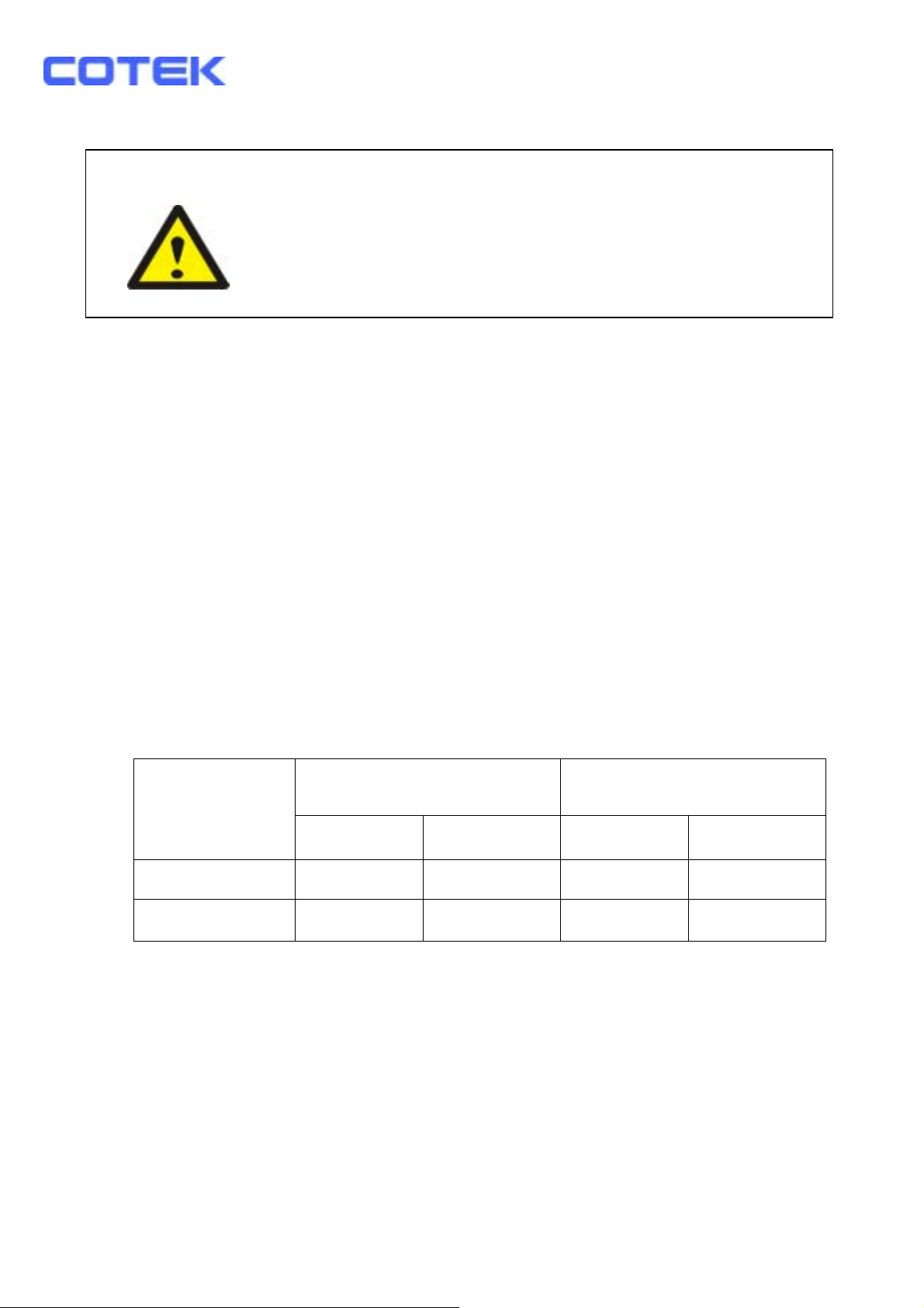
DC input voltage status as follows:
Model
DC Input Over
Voltage
DC Input Under
Voltage
Shut-down Restart Shut-down Restart
12V models 15.3 14.8 10.5 12.5
24V models 30.6 29.6 21.0 25.0
10
Page 11
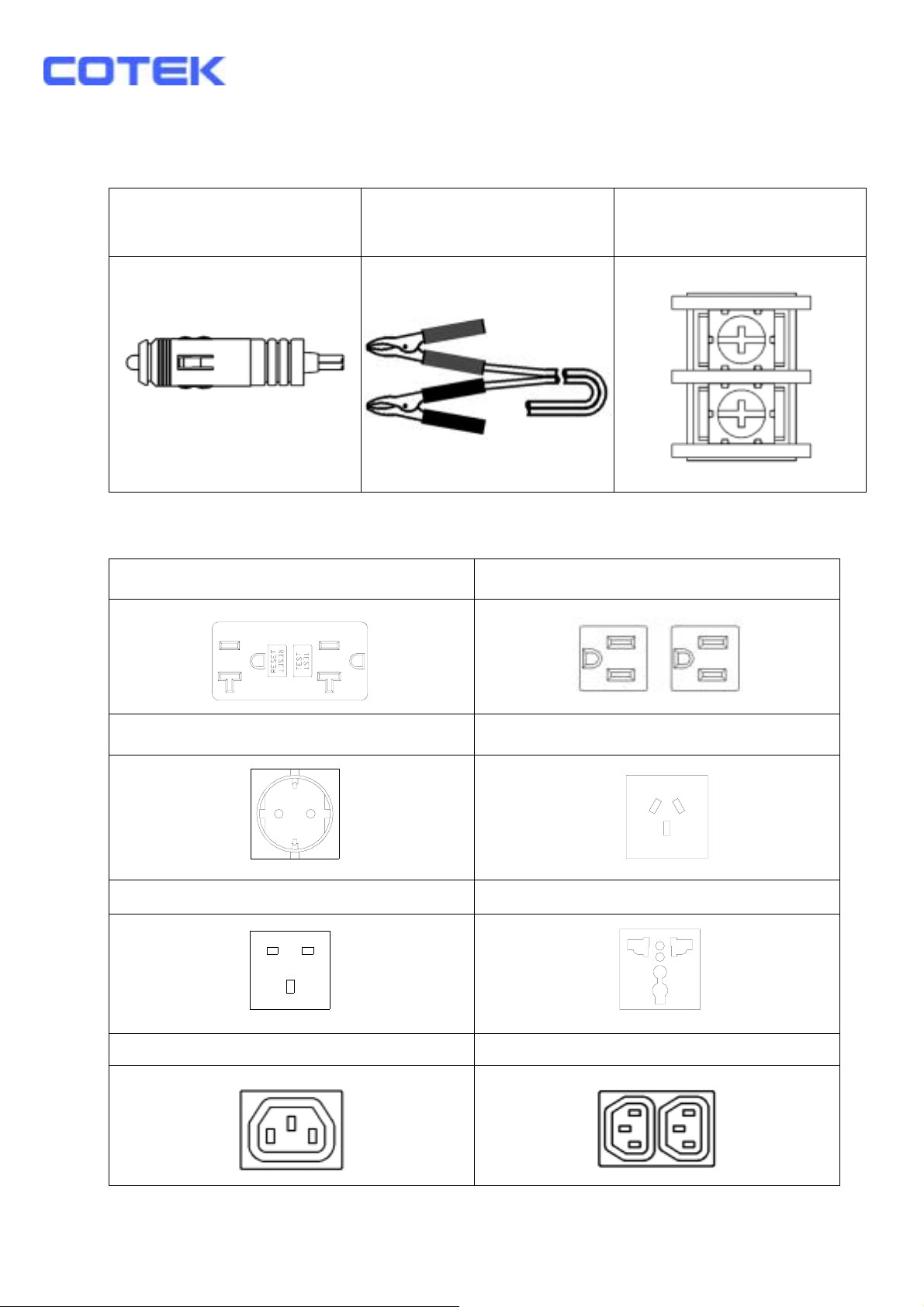
3-5. DC Input (Outlet sockets available):
CIGARET CLAMP TERMINAL
3-6. AC output (Outlet sockets available):
North America (GFCI) North America
Continental European (SCHUKO) Australia / New Zealand
United Kingdom
Universal
IEC-1 IEC-2
11
Page 12
4. Troubleshooting guide:
WARNING!
Do not open or disassemble the Inverter. Attempting to
service the unit yourself may result in a risk of electrical
shock or fire.
Problems and Symptoms Possible Cause Solutions
No output voltage, the LED glows RED light.
a. Power status light is
blinked red fast.
b. Power status light is
blinked red slowly.
c. Power status light is
blinked red
Intermittently.
d. Power status light is
glowed red steadily.
Over input voltage.
Low input voltage.
Thermal shutdown
Short circuit, Wiring
error,
Over Load
Check input voltage.
Reduce input voltage.
Recharge battery.
Check connections
and cable.
Improve ventilation.
Make sure ventilation
openings in inverter
are not obstructed.
Reduce ambient
temperature.
Check AC wiring
for short circuit.
Remove load.
12
Page 13

5. Maintenance:
Very little maintenance is required to keep your inverter operating properly.
You should clean the exterior of the unit periodically with a damp cloth to
prevent accumulation of dust and dirt.
At the same time, tighten the screws on the DC input terminals.
6. Warranty:
We warrant this product against defects in materials and workmanship for a
period of 24 months from the date of purchase and will repair or replace any
defective Power Inverter when directly returned, postage paid, to us.
This warranty will be considered void if the unit has suffered any obvious
physical damage or alteration either internally or externally and does not
cover damage arising from improper use such as plugging.
The unit into an unsuitable power sources attempts to operate products with
excessive power consumption requirements, or use in unsuitable environments.
This is the only warranty that the company makes.
No other warranties express or imply including warranties of merchantability
and fitness for a particular purpose.
Repair and replacement are your sole remedies and the company shall not be
liable for damages, whether direct, incidental, special or consequential, even
though caused by negligence or other fault.
13
Page 14

Distributed by Power Sources Unlimited, Inc.
200 Stonewall Blvd, Suite 4, Wrentham, MA 02093
P 800-966-PSUI (7784) or 508-384-1419 F 508-384-1896
14
 Loading...