

Page 1

OWNER’S INSTRUCTION
MANUAL
Four Line Auto-Attendant/Answering System
MODEL 2750
Page 2

Table of Contents
1. UNPACKING AND INSTALLATION.......................................................................4
1.1 Box Contents .............................................................................................................4
1.2 Telephone Part Identification .....................................................................................5
1.3 Installation................................................................................................................6
1.3.1 Overview ..................................................................................................................6
1.3.2 Before Installation ....................................................................................................6
1.3.3 Installation Configurations........................................................................................6
1.3.3.1 Standard Configuration.............................................................................................6
1.3.3.2 Private Line ..............................................................................................................6
1.3.3.3 Unconnected Lines ...................................................................................................6
1.3.3.4 Line 1 .......................................................................................................................6
1.3.4 Phone Installation .....................................................................................................7
1.3.4.1 Desk Mount..............................................................................................................7
1.3.4.2 Wall Mount...............................................................................................................7
1.3.4.3 Install Batteries (Optional)........................................................................................7
1.3.4.4 Assign a Station Number ..........................................................................................8
1.3.5 Test Installation.........................................................................................................8
2. SYSTEM PROGRAMMING....................................................................................9
2.1 Station Number Assignment......................................................................................9
2.2 Station Name Assignment .........................................................................................9
2.3 Line Configuration/Type .........................................................................................10
2.3.1 Line Connections/Configuration .............................................................................10
2.4 Loop Voltage Detector ............................................................................................10
2.5 Ringer Configuration ..............................................................................................12
2.5.1 Ring Timing............................................................................................................12
2.5.2 Distinctive Ringing.................................................................................................12
2.5.3 Off-Hook Ringing...................................................................................................13
2.6 Intercom Call Response ..........................................................................................13
2.6.1 Configuring intercom call response:........................................................................13
2.7 Automatic Line Selection........................................................................................14
2.8 Toll Restriction .......................................................................................................14
2.8.1 To set the system’s toll restriction access code: .......................................................14
2.8.2 Setting the restricted numbers .................................................................................14
2.8.3 Allowed numbers ....................................................................................................15
2.8.4 Toll restriction override..........................................................................................15
2.8.5. Line restriction........................................................................................................15
2.9 System Privacy ....................................................................................................... 16
2.10 Dialing Mode.......................................................................................................... 16
2.11 Area Codes .............................................................................................................17
2.11.1 Home Area Code .................................................................................................... 17
2.11.2 Local Area Codes....................................................................................................17
2.11.3 1 Plus 7...................................................................................................................17
i
Page 3

3. MEMORY SETTINGS ...........................................................................................18
3.1. Memory Features.................................................................................................... 18
3.1.1 Storing a hyphen into memory ................................................................................18
3.1.2 Storing a dialing pause into memory .......................................................................18
3.1.3 Storing a flash into memory ....................................................................................18
3.1.4 Storing temporary tone dialing into memory ...........................................................18
3.1.5 Storing one of the last five numbers dialed into memory .........................................18
3.1.6 Storing a Caller ID number into memory ................................................................18
3.2 To store a personal directory dial number................................................................18
3.3 To Store Caller ID Records .....................................................................................19
3.4 To Store the Centrex Prefix .....................................................................................19
3.4.1 To Set the Centrex Prefix ........................................................................................19
4. MISCELLANEOUS SETTINGS ............................................................................19
4.1 Time and Date.........................................................................................................19
4.2 Message Waiting Lamp...........................................................................................20
4.2.1 Message Waiting Line Selection ............................................................................. 20
4.2.2 Message Waiting Mode Selection............................................................................ 20
4.3 Caller ID on Call Waiting (CIDCW) Sensitivity...................................................... 20
4.4 Hold Call Reminder ................................................................................................21
4.5 Adjusting Auto Hold Drop Time .............................................................................21
4.6 Adjusting Flash Timer.............................................................................................21
4.7 Erase Numbers Stored in Memory...........................................................................21
4.8 Erase Toll Restrictions ............................................................................................22
4.9 Erase All Feature Settings .......................................................................................22
4.10 Reset Default Settings.............................................................................................22
5. ANSWERING SYSTEM ........................................................................................22
5.1 Setting Answering Option....................................................................................... 22
5.1.1 Turn on Answering Machine ...................................................................................22
5.1.2 Record your OGM ..................................................................................................23
5.1.2.1 Reviewing your OGM. ...........................................................................................23
5.1.2.2 Erasing your OGM. ................................................................................................23
5.1.2.3 Changing your OGM. .............................................................................................23
5.1.3 Setting Your Telephone's Pickup Delay ................................................................... 23
5.1.4 Setting Toll Saver....................................................................................................24
5.1.5 New Message Beep.................................................................................................24
5.1.6 Remote Code ..........................................................................................................24
5.1.6.1 Setting the remote code...........................................................................................25
5.1.6.2 Checking Messages Remotely ................................................................................25
5.1.7 Setting Message Length ..........................................................................................25
5.2 Auto-Attendant .......................................................................................................25
5.2.1 Set up the Auto Attendant .......................................................................................26
5.2.2 Record the Auto Attendant Day OGM.....................................................................26
5.2.3 Record the Auto Attendant Night OGM ..................................................................26
5.2.4 Record the Auto Attendant Zero-Out OGM.............................................................27
5.2.5 Setting Auto Attendant Pickup Delay ......................................................................27
ii
Page 4

5.2.6 Night Timer Set ...................................................................................................... 27
5.2.7 Setting More Than One Phone as an Auto Attendant ...............................................28
5.2.8 Using Additional Auto Attendant OGMs .................................................................28
5.2.9 Setting Separate Auto Attendant OGM's for Different Lines....................................28
5.2.10 Turn Off the Auto Attendant on One or More Lines.................................................28
5.2.11 Choosing the Zero-Out Action ................................................................................ 29
5.2.12 All Transfer Feature ................................................................................................29
5.2.13 Leave a Message at the Auto Attendant...................................................................29
5.2.14 Set Night Message by Line .....................................................................................29
5.2.15 Transfer Directly to Voice Mail ...............................................................................30
5.2.16 Repeating the Main Menu and Messages.................................................................30
5.2.17 Summary of Auto Attendant Actions ....................................................................... 30
5.3 Voicemail................................................................................................................30
5.3.1 Activation ...............................................................................................................31
5.3.2 Message Notification ..............................................................................................31
5.3.3 Play Messages ........................................................................................................31
5.3.4 Stop Message Playback...........................................................................................31
5.3.5 Pause Message Playback.........................................................................................31
5.3.6 Repeat a Message ................................................................................................... 31
5.3.7 Skip to the next Message.........................................................................................31
5.3.8 Jump Backward ...................................................................................................... 32
5.3.9 Jump Forward.........................................................................................................32
5.3.10 Saving a Message as New .......................................................................................32
5.3.11 Message Auto Save.................................................................................................32
5.3.12 Increase Playback Speed.........................................................................................32
5.3.13 Decrease Playback Speed........................................................................................32
5.3.14 Erasing Messages....................................................................................................32
5.3.14.1 Erase a Single Message...........................................................................................32
5.3.14.2 Erase All Messages .................................................................................................32
5.3.15 Using Dial Pad........................................................................................................32
5.3.16 Recording a Memo or Conversation........................................................................33
5.3.16.1 Recording a Memo .................................................................................................33
5.3.16.2 Recording a Telephone Conversation. .....................................................................33
5.3.17 Screening Calls.......................................................................................................33
6. TELEPHONE OPERATION...................................................................................33
6.1 Making and Answering Calls ..................................................................................33
6.2 Redial ..................................................................................................................... 34
6.2.1 To redial the last phone number dialed ....................................................................34
6.2.2 To redial any of the last five phone numbers dialed ................................................. 34
6.3 Hold........................................................................................................................34
6.3.1 Placing a Call on Hold ............................................................................................34
6.3.2 Making a call on another line ..................................................................................34
6.3.3 Answering a call on another line .............................................................................34
6.4 Conference .............................................................................................................34
6.4.1 Outside Calls ..........................................................................................................35
iii
Page 5

6.4.2 Outside Call with Intercom Station ......................................................................... 35
6.5 Transfer ..................................................................................................................35
6.5.1 Attended Transfer....................................................................................................35
6.5.2 Blind Transfer ......................................................................................................... 35
6.5.3 Transfer Ring..........................................................................................................35
6.5.4 Personal Ring..........................................................................................................36
6.6 Caller ID.................................................................................................................36
6.6.1 Incoming call..........................................................................................................36
6.6.2 Call Waiting Caller ID ............................................................................................ 36
6.6.3 Caller List...............................................................................................................36
6.6.3.1 Reviewing Calls .....................................................................................................36
6.6.3.2 Dialing Calls...........................................................................................................37
6.6.3.3 Deleting Numbers...................................................................................................37
6.7 Volume Levels ........................................................................................................37
6.7.1 Ringer.....................................................................................................................37
6.7.2 Handset...................................................................................................................37
6.7.3 Speakerphone .........................................................................................................37
6.7.4 Intercom Speaker.................................................................................................... 37
6.7.5 Discrete alert...........................................................................................................37
6.8 Voice Mail (Message Waiting) ................................................................................37
6.8.1 Accessing Messages................................................................................................ 38
6.8.2 Resetting MSG Lamp .............................................................................................38
6.9 FLASH ...................................................................................................................38
6.10 Mute ....................................................................................................................... 38
6.11 Do Not Disturb (DND) ...........................................................................................38
6.12 Line Reserve...........................................................................................................39
6.13 Call Privacy ............................................................................................................39
6.14 Toll Restriction .......................................................................................................39
6.14.1 Toll Restriction Removal (Single Call)....................................................................39
6.14.2 Toll Restriction Removal (Single Station) ...............................................................39
6.15 Timer ......................................................................................................................39
6.15.1 Elapsed Call Time...................................................................................................39
6.15.2 Timer Reset ............................................................................................................40
6.15.3 Elapsed Call Time (Previous Calls).........................................................................40
6.16 Headset...................................................................................................................40
6.17 Directory Card ........................................................................................................40
6.18 Personal Directory ..................................................................................................40
6.19 Predialing ...............................................................................................................40
6.20 Intercom Calls ........................................................................................................40
6.20.1 Intercom while Idle.................................................................................................41
6.20.2 Intercom while on an Outside Call ..........................................................................41
6.20.3 Answering Intercom Calls.......................................................................................41
6.20.3.1 Intercom Ring.........................................................................................................41
6.20.3.2 Intercom Voice........................................................................................................41
6.20.3.3 Intercom Handsfree ................................................................................................41
iv
Page 6

6.20.3.4 Answering an Intercom Call while on an Outside Call ............................................41
6.21 Paging.....................................................................................................................41
6.21.1 Single Page.............................................................................................................41
6.21.2 All Page ..................................................................................................................41
6.21.3 Blocking Pages ....................................................................................................... 42
6.21.4 Answering Pages.....................................................................................................42
6.21.4.1 Single Page..............................................................................................................42
6.21.4.2 All Page...................................................................................................................42
6.22 Room Monitoring ...................................................................................................42
7. USING STANARD TELEPHONES .......................................................................42
7.1 Line Status and Calls on Hold .................................................................................43
7.2 Call Privacy ............................................................................................................43
7.3 Intercom .................................................................................................................43
7.4 Fax Machines and Modems.....................................................................................43
8. POWER FAIL OPERATION ..................................................................................43
APPENDIX A.....................................................................................................................................44
Menu Tree...........................................................................................................................................44
Phone Settings ....................................................................................................................................44
Answer Settings ..................................................................................................................................46
Memory Settings.................................................................................................................................47
Time and Date Settings .......................................................................................................................47
Advanced Settings ..............................................................................................................................47
APPENDIX B - Installation Worksheet ...............................................................................................48
APPENDIX C - Toll Restriction Worksheet ........................................................................................49
APPENDIX D - Trouble Shooting Guide ...........................................................................................50
FCC INFORMATION.........................................................................................................................51
TELEPHONE REPAIR.......................................................................................................................52
LIMITED WARRANTY .....................................................................................................................53
v
Page 7

THANK YOU
FOR PURCHASING THE
2750
Four Line Auto-Attendant/Answering Telephone
We want you to know all about your new Telephone.
How to install it, the features it provides, and the services you can expect from its use. We have
included this information in your Owner’s Instruction Manual.
The 2750 is one of our new Series 7 Telephones. It is a stand alone 4-Line Telephone or part of a 4Line system consisting of up to 16 stations of 2740's, 2742's, or 2750's. The 2740 is our base unit. It
has 4 line buttons, Intercom, Conference, Page, Transfer, Mute, Headset, Flash, Redial, Hold, 5
memory dial buttons, 40 Number Personal Directory, Type II Caller ID, Speakerphone, and 2.5mm
Headset Jack.
The 2742 Analog Adapter will support attaching an analog telephone to your 4-Line system. For
example you can connect a cordless telephone, fax machine, or modem. These units will have an
extension number and can share all 4 lines.
The other telephone in our system is the model 2740. The 2740 has the same features as the 2750
except for the Answering System.
2
Page 8

PLEASE READ BEFORE INSTALLING AND USING YOUR NEW
TELEPHONE EQUIPMENT.
SAFETY INSTRUCTIONS
Always follow basic safety precautions
fire, electrical shock, and injury.
1.
Read and understand all instructions
2.
Read all warnings
3.
Unplug this product from the wall outlet before cleaning
not use liquid or aerosol cleaners.
4.
Do not use the telephone near water
kitchen sink, laundry tub, swimming pool, or in a wet basement.
5.
Do not place this product on an unstable cart or stand
damage to the product.
6.
Use only the type power source indicated on the label.
supply to your home, consult your dealer or local power company.
7.
Do not place any objects on the telephone line cord
line cord will be walked on.
8.
Do not block or cover ventilation slots and openings
openings should never be blocked by placing the telephone on a bed, sofa, rug, or other similar
surfaces. The telephone should never be placed near or over a radiator or heat register. The
telephone should never be placed in a built-in installation unless proper ventilation is provided.
9.
Never spill liquid on the telephone or push objects of any kind through ventilation slots
Liquid or objects may touch dangerous voltage points or short out parts that could result in a
risk of fire or electrical shock.
10.
Do not disassemble this product
voltages or other risks. Incorrect reassembly can cause electrical shock when the product is
subsequently used.
11.
Do not overload outlets and extension cords.
outlet. Overloading the outlets can result in the risk of fire or electric shock.
12.
Avoid using a telephone during a local thunderstorm
electrical shock from lightning.
13.
Use only the power cord and batteries indicated in this manual
in a fire. They may explode. Check with local codes for possible special disposal instructions.
14.
Do not use a telephone to report a gas leak in the vicinity of the leak.
and follow all instructions marked on the product.
when using your telephone equipment to reduce the risk of
in the Owner’s Instruction Manual.
. Use a damp cloth for cleaning. Do
. For example, do not use near a bathtub, wash bowl,
. The product may fall causing serious
If you are not sure of the type power
. Do not locate the telephone where the
in the bottom of the telephone. The
. Opening or removing covers may expose you to dangerous
Some telephones require AC power from an
. There may be a remote risk of
. Do not dispose of batteries
.
3
Page 9

1. UNPACKING AND INSTALLATION
1.1 Box Contents
The following items should be packed with your 2750. Please contact your dealer if any of them is
missing.
2750 Phone (Main Body) 1 pcs
Handset 1 pcs
Handset Cord (Coiled Cord) 1 pcs
Line Cord 7ft 2 pcs
Short Line Cord 7” 1 pcs
Desk Stand 1 pcs
Power Adapter (Transformer 9VDC 500 ma) 1 pcs
Quick Start Guide 1 pcs
User Manual on Mini CD 1 pcs
4
Page 10
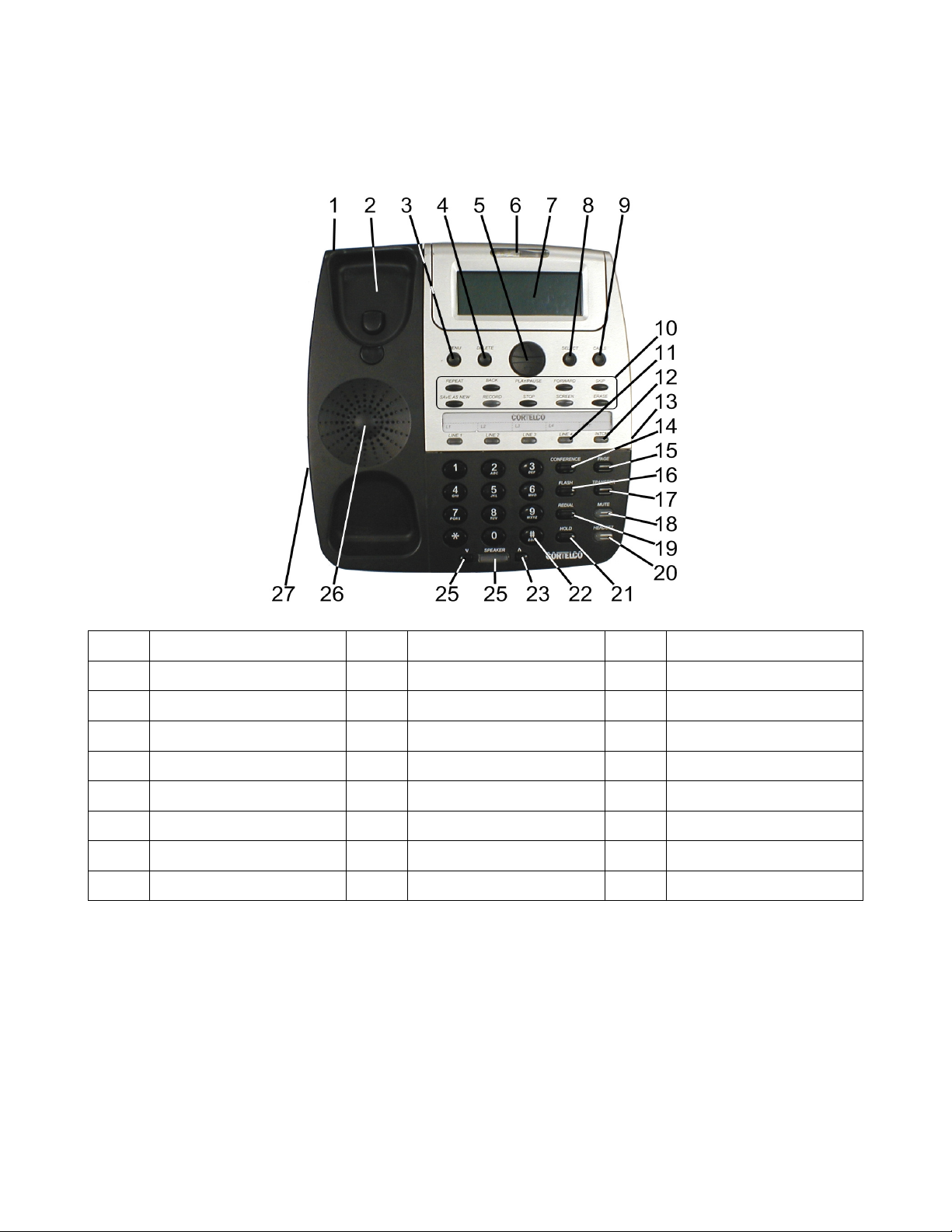
1.2 Telephone Part Identification
1 Telephone Base 10 VM Buttons (See below) 19 Redial Button
2 Handset Cradle 11 Line Buttons 20 Headset Button
3 Menu Button 12 Intercom Button 21 Hold Button
4 Delete Button 13 2.5mm Headset Jack 22 Key Pad Buttons
5 Review Up/Down Btn 14 Conference Button 23 Volume Up Button
6 Message Lamp 15 Page Button 24 Speaker Button
7 Multi-Angle LCD 16 Flash Button 25 Volume Down Button
8 Select Button 17 Transfer Button 26 Speaker
9 Calls Button 18 Mute Button 27 Handset Jack
Voice Mail Buttons (Item 10)
5
Page 11

1.3 Installation
1.3.1 Overview
The 2750 is part of the 7 Series Multiline phone system. Up to 16 instruments may be connected in
this system. All these devices use conventional telephone wiring. Wiring runs between stations may be
a maximum of 600 feet.
1.3.2 Before Installation
In order to install your telephones correctly, you must determine the incoming wiring configuration. In
most cases, incoming lines will be terminated in either RJ11 Single Line Jacks or RJ14 Double Line
Jacks. If you are not sure of your incoming line configuration, contact your telephone line installer.
All connection between the wall jacks and the telephones may be done with standard telephone
modular cords. Please be sure that your modular cords have at least 4 wires in them.
If you have RJ11 jacks, you will need two line adapters (not included) to connect to the 2750. These
couplers take the single line wiring and convert it to double line wiring. These couplers should be
available where you purchased your 2750.
1.3.3 Installation Configurations
1.3.3.1 Standard Configuration
The 2750 is initially configured so that each line is common at all stations. In other words, Line 1 at
each telephone is connected to the same incoming line; Line 2 at each station is connected to the same
incoming line, etc. This is commonly known as a “square system.” If this is suitable for your
installation, you only need to connect the telephones to the telephone lines.
1.3.3.2 Private Line
A private line is connected to only one telephone in the system. No other phones in the system have
access to this telephone line.
1.3.3.3 Unconnected Lines
It is also permissible to leave one or more lines unconnected.
1.3.3.4 Line 1
Line 1
MUST
be connected to the same incoming line on all phones for the system to function
correctly.
6
Page 12
1.3.4 Phone Installation
1.3.4.1 Desk Mount
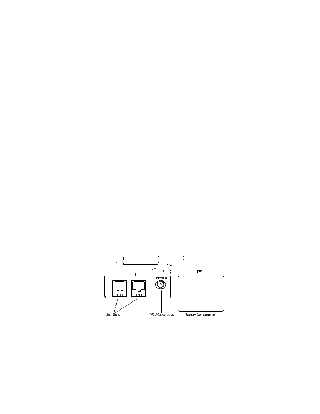
a. Connect the power adapter to the jack on the bottom of the phone. Plug the adapter into a wall
outlet which is not controlled by a wall switch. Use only a 9V DC 500mA, Class 2 adapter.
b. Connect the line cords. If you have RJ14 line jacks, you need only connect 4 wire line cords
between the wall jacks and the jacks in the base of the 2750. If you have RJ11 line jacks, you
will need 2 line couplers as discussed in Section 1.3.2. Note that the jacks on the 2750 are
numbered L1/L2 and L3/L4. Connect your incoming lines accordingly.
c. Select the desired viewing angle and install the desk stand. The desk stand can be installed in
two positions to give a choice of viewing angle.
d. Plug the coiled cord into the handset jack, and plug the other end of the cord into the base.
e. Place the handset on the base.
1.3.4.2 Wall Mount
a. Remove the desk stand. The unit will then mount directly on a standard wall telephone jack.
b. Connect the power adapter and the line cords. See Steps “a” and “b” above. Use the included
short line cord to connect to the mounting jack. Use one of the included long line cords to
connect to the other jack.
c. Mount telephone to wall jack (RJ-11W).
d. Plug the coiled cord into the handset, and then plug the other end of the cord into the base.
e. Rotate the handset hook into the wall mount position and place the handset on the base.
1.3.4.3 Install Batteries (Optional)
The 2750 uses AC power from a standard wall outlet. As long as the telephone is connected to a wall
outlet, it will operate using the AC power.
that is not controlled by a wall switch.
batteries fit into a compartment on the base of the telephone.
The display has a battery symbol whenever the batteries are low and need replacing or when no
batteries are installed.
Please remember to plug your telephone into a wall outlet
The 2750 uses 3 AAA batteries for backup power. These
7
Page 13

Follow the instructions below to install or replace the batteries.
a. Make sure the AC cord is attached to the telephone and to a working electrical outlet.
b. Turn the telephone over.
c. Remove desk pedestal/wall mount bracket if attached.
d. Remove battery door cover by using the tip of a ball-point pen, paper clip, or similar object to
release the battery door tab.
e. Remove the old battery.
f. Insert 3 new AAA size alkaline batteries. Note that we recommend ONLY alkaline batteries.
g. Close the battery cover.
1.3.4.4 Assign a Station Number
Station 01 must be the first extension number assigned.
features on the 2750. Refer to Section 2.1 for detailed instructions on assigning station numbers.
1.3.5 Test Installation
This procedure should be used at each telephone after initial installation. It may also be used if you are
having problems with your system. First, verify the three items below at each telephone in the system.
a. Verify that the AC power transformer is connected to the 2750 and to mains power.
b. Verify that Line 1 is connected to the 2750.
c. Verify that a station number has been assigned.
Now, verify that Line 1 has been connected correctly to all telephones.
d. Press Line 1 at one telephone.
e. Verify that the Line 1 LED is Green, the Speakerphone LED is red and that dial tone is heard.
f. Verify that the Line 1 LED is red at each other station.
To verify the connection of lines 2 – 4, perform the following steps at each telephone.
a. Press Line 1.
b. Verify that the Line 1 LED is Green, the Speakerphone LED is red and that dial tone is heard.
c. Dial the telephone number for Line 2. Verify that the Line 2 LED flashes slowly. If it does not
flash, Line 2 may not be properly connected.
d. Repeat the steps above using the telephone numbers for Lines 3 and 4 if applicable. Remember
that Lines 2, 3, and 4 may not be common at all telephones.
Station 01 is required for programming
8
Page 14

2. SYSTEM PROGRAMMING
2.1 Station Number Assignment
Each station must be assigned a unique station number.
until a station number is assigned.
a. Press
b. Press the soft key under
c. Press the soft key under
d. Press
Note:
function. Certain Features can only be programmed at station 01 and will only function at station 01.
2.2 Station Name Assignment
You may give a name to each of your telephones. During Intercom calls, the name that is assigned to
the station will show with the Extension Number. Please note that it may take up to 24 hours for all
stations to be updated with a name change.
the steps below to assign a station name.
a.
b.
c.
d.
e.
f.
g.
Repeat these steps for any additional stations you wish to name. The following table below shows
which dialpad numbers to press for letters and special characters. Press the down arrow button below
the display to leave an empty space. Press the
One phone in the system must be set as Station #01 in order for all the system features to
MENU
The choices are Station #01 through Station #16.
MENU
Press
MENU
Press soft key under
Press the
Press soft key under
or indicate “No Name” if no name has yet been given to station #01.
Press soft key under
DOWN ARROW
press soft key under
Use the dialpad numbers to enter the name for the desired station. Names may contain up to 16
characters.
Press the soft key under
. The display will read “
to exit.
. The display will read “
ENTER.
Down Arrow
ENTER.
CHANGE
repeatedly until you see the station number that you want to name, and then
CHANGE
To assign a number to a station:
Phone Setting
ENTER
CHANGE
repeatedly until the display reads “
SAVE.
. The display will show the currently assigned station number.
repeatedly, until the desired station number is displayed.
Station names must be assigned at Station 01.
Phone Setting
The display will show the currently stored name for station #01,
if you wish to store a new name for station #01, or press
.
DELETE
2750 telephones will not function correctly
”
Follow
”
Station Naming
button to make corrections.
”
0 0
1 , - ' & . ( ) 1
2 a b c 2 A B C
3 d e f 3 D E F
4 g h i 4 G H I
9
Page 15

5 j k l 5 J K L
6 m n o 6 M N O
7 p q r S 7 P Q R S
8 t u v 8 T U V
9 w x y Z 9 W X Y Z
* *
# #
2.3 Line Configuration/Type
While Line 1 must be shared at all stations, Lines 2, 3 or 4 may be unconnected or may be connected to
private lines.
COMMON:
This is the factory setting for all lines. This setting assumes that the line is connected to
the same telephone number at all stations.
PRIVATE:
Use this setting at any telephone that is connected to a different telephone number than the
corresponding line at the other stations. For example, you may connect your private telephone number
to Line 3 at your station instead of connecting your station to the common Line 3. In this example, you
would set Line 3 at your station as PRIVATE.
UNCONNECTED:
Use this setting at any telephone that is not physically connected to all of its lines.
2.3.1 Line Connections/Configuration
a.
b.
c.
d.
e.
Press
MENU
Press soft key under
Press the
DOWN ARROW
Press soft key under
Press the soft key under
. The display will read “
ENTER.
repeatedly until the display reads ”
ENTER
. The display will show the line connection setting for Line 2.
CHANGE
Phone Setting.
”
Line Connections.
”
repeatedly, until the desired line connection setting for Line
2 is displayed. The choices are:
L2: COMMON (factory setting)
L2: PRIVATE
L2: UNCONNECTED
f.
Press the soft key under
NEXT
to see the current setting for Line 3, and repeat steps c, d, and e
to change the settings for Lines 3-4.
g.
Press
MENU
to exit.
2.4 Loop Voltage Detector
The status indicators of your 2750 telephone are designed to light when a fax machine, modem, or
standard telephone is using a line. If the line status indicators of your 2750 telephones light when no
telephone is using the line or do not light when a standard telephone is using the line, the loop voltage
detector setting may need to be adjusted. The factory setting of 48 volts is appropriate for most
10
Page 16

installations. This value can be changed to either 24 volts or 12 volts or the feature can be turned off.
To set Loop Voltage Detector
a.
b.
c.
d.
Press
MENU.
Press
DOWN ARROW
Press soft key under
Press
DOWN ARROW
current setting
repeatedly until “
ENTER
.
repeatedly until “
Advanced Setting
Loop Detect
:” appears in the display, along with the
” appears in the display.
11
Page 17

e.
Press the soft key under
CHANGE
repeatedly until the desired loop detect setting is displayed.
The choices are:
Loop Detect: 48V (factory setting)
Loop Detect: 24V (24 volts)
Loop Detect: 12V
Loop Detect: OFF
f.
Press
MENU
to exit.
If a line indicator at your 2750 telephone stays lit because there is no telephone line connected, and you
wish to turn it off, do not use this feature, but set this line at this station to UNCONNECTED
2.5 Ringer Configuration
The ringers for each outside line are controlled individually at each telephone. There are three possible
settings for each line ringer:
RINGER ON
DELAYED RING
: The line will ring normally.
: The line will start ringing after the first 20 seconds. This is useful if all phones are
answered at a central location.
RINGER OFF
: The line will not ring. In all these cases, the line indicators will flash to signal an
incoming call.
You can always answer a ringing line, whether or not it is ringing audibly at your telephone, by
pressing the flashing line button.
2.5.1 Ring Timing
a. Press MENU. The display will read “Phone Setting”
b. Press soft key under ENTER.
c. Press the Down Arrow repeatedly until “Ringer Settings” appears in the display.
d. Press soft key under ENTER. The display will show the current ringer setting for Line 1.
e. Press the soft key under CHANGE repeatedly, until the desired ringer setting for Line 1 is
displayed. The choices are:
L1 Ringer: ON (factory setting)
L1 Ringer: DELAY
L1 Ringer: OFF
f. Press the soft key under DOWN ARROW to see the current ringer setting for Line 2. Repeat
steps c - e to change the ringer settings for Lines 2-4.
g. Press MENU to exit.
2.5.2 Distinctive Ringing
All lines are initially set to ring with Ring Sound #1. Each outside line may be assigned one of seven
other distinctive ringer tones. This can be used to easily identify a ringing line or ringing phone. To
assign distinctive rings to one or more lines:
a.
b.
c.
Press
MENU
Press the
Press soft key under
. The display will read “
DOWN ARROW
ENTER.
Phone Setting
repeatedly until ”
Distinctive Ring
”
” appears in the display.
The display will show the distinctive ring setting for Line 1.
12
Page 18

d.
Press the soft key under
CHANGE
repeatedly, until the desired distinctive ring setting for Line
1 is displayed. There are eight choices.
e.
Press the
DOWN ARROW
to see the current setting for Line 2, and repeat steps c and d to
change the settings for Lines 2-4.
f.
Note:
Press
MENU
to exit.
When a distinctive ring setting is displayed, it may be heard by pressing the soft key under
CHANGE.
2.5.3 Off-Hook Ringing
When a ringer is set to
ON
or
DELAYED
, an incoming call will cause a double ring every 15 seconds
is the phone is in use. This feature is called “off-hook ringing” and can be disabled. To disable offhook ringing
a.
b.
Press
MENU.
Press the soft key under
NEXT
repeatedly until “Off Hook Ring” appears in the display, along
with the current setting.
c.
d.
Note:
Press the soft key under
Press
MENU
CHANGE
to exit.
to change the setting.
Off-Hook ringing does not function on intercom calls. However, the line lamps will flash to
indicate an incoming call.
2.6 Intercom Call Response
The 2750 may be configured to respond to intercom calls in one of three ways:
INTERCOM HANDSFREE:
When an intercom call is received, the telephone will ring once and then
give a triple alert tone. The phone will then automatically answer the intercom call on speakerphone.
INTERCOM RING:
intercom ring. The call may be answered by lifting the handset or pressing the
INTERCOM VOICE:
When an intercom call is received, the telephone will ring repeatedly with the
SPEAKER
button.
When an intercom call is received, the telephone will ring once and then give an
alert tone. After this the calling party will be connected. To respond to the calling party, either lift the
handset or press the
Note:
When an intercom call is received while an outside call is in progress, the 2750 will ring with a
SPEAKER
button.
single intercom ring regardless of the intercom ringer setting
2.6.1 Configuring intercom call response:
a.
b.
c.
d.
e.
f.
Press
MENU
Press soft key under
Press the
Down Arrow
Press soft key under
Press the soft key under
Press
MENU
. The display will read
ENTER.
repeatedly until
ENTER
. The display will show the current intercom setting.
CHANGE
to exit.
Phone Setting
Intercom Prefs
appears in the display.
repeatedly, until the desired intercom setting is displayed.
13
Page 19

2.7 Automatic Line Selection
The 2750 will automatically select an outside line or the intercom line whenever the handset is lifted or
the SPEAKER button is pressed. To choose which line will be automatically selected:
a.
b.
Press
MENU
Press the soft key under
. The display will read
ENTER
.
Phone Setting
c. Press the DOWN ARROW repeatedly until Auto Seize appears in the display. The display will
show the current auto seize setting.
d. Press the soft key under CHANGE repeatedly, until the desired setting is displayed. The
choices are L1, L2, L3, L4 or INTCM.
e.
Note:
or
ringing line, the desired
Note:
Press
MENU
to exit.
An incoming call that will be selected automatically when the handset is lifted or the
HEADSET
button is pressed, regardless of the automatic line selection choice. To select a non-
LINE
button must be pressed before lifting the handset.
If the chosen line is in-use, the telephone will automatically select the next available line.
SPEAKER
2.8 Toll Restriction
Toll Restriction enables control of outgoing calls. The 2750 accomplishes toll restriction by allowing
entry of number strings which may not be dialed. This is done on a station-by-station basis so different
phones may have differing toll restrictions. This may be used to help prevent unauthorized long
distance calls.
For example, to prevent dialing of “900” numbers, the code 1900 should be entered as a toll restriction.
This would prevent the station from dialing any numbers beginning with 1900.
A “#” character may be entered as a wildcard which matches either 0 or 1. If #900 had been entered in
the example, the station would not dial numbers beginning with either 1900 or 0900.
A toll restriction access code is needed to change or add toll restrictions. This code must be set at
station #01.
2.8.1 To set the system’s toll restriction access code:
At Station #01:
a.
b.
c.
d.
e.
f.
Press
MENU
Press the
DOWN ARROW
Press the soft key under
Press the soft key under
Enter a 4 digit number.
Press
MENU
. The display will read “
repeatedly until “
ENTER
. The display will read “
CHANGE
to exit.
Phone Setting
”
Toll Restriction
Access Code:****
to store a new access code.
” appears in the display.
.”
Note that the previous code is not needed to set a new code. The factory default code is 1234.
2.8.2 Setting the restricted numbers
After toll restrictions are set at a phone, they will be retained even after a power failure.
To set restricted numbers at a station
a.
b.
Press
MENU
Press the
. The display will read
DOWN ARROW
Phone Setting
repeatedly until
Toll Restriction
appears in the display.
14
Page 20

c. Press the soft key under ENTER. The display will read Enter Code: [all stations other than
#01]
d. Enter the 4 digit toll restriction access code which was set at Station #01. A confirmation beep
will sound and the display will read Set Restricted #
e.
Press the soft key under
ENTER.
The display will show the currently stored Restriction #1, or
show 1: if no Restriction #1 has been stored.
f.
g.
Press the soft key under
Dial desired restricted number, up to 6 digits.
CHANGE
.
h. Press the soft key under SAVE.
i. Press the DOWN ARROW and repeat steps f-h to store any additional restrictions at this
station.
2.8.3 Allowed numbers
After setting toll restrictions, it is sometimes necessary to enter some exceptions which may be dialed.
For example, if “1” had been entered to completely restrict long distance calls, toll free calls could be
allowed by entering “1800” as an allowed number. The “*” character may be used as a wildcard which
matches any digit. Allowed numbers may contain up to 10 digits.
To set allowed numbers at a station
a.
b.
c.
d.
Press
MENU
Press the soft key under
Press the
DOWN ARROW
Press the soft key under
. The display will read “
ENTER.
repeatedly until “
ENTER
. The display will read “
Phone Setting
Toll Restriction
”
Enter Code:
” appears in the display.
”
e. Enter the 4 digit toll restriction access code. A confirmation beep will sound and the display will
read “Set Restricted #”
f.
g.
Press the soft key under
Press the soft key under
NEXT
. The display will read “
ENTER.
Set Allowed #
”
The display will show the currently stored Allowed #1, or 1:
if there is no Allowed #1 yet stored.
h.
i.
j.
k.
Press the soft key under
Dial desired allowed number, up to 10 digits.
Press the soft key under
Press the soft key under
CHANGE
SAVE
.
DOWN ARROW
and repeat steps g-j if you wish to store any
additional allowed numbers at this phone.
2.8.4 Toll restriction override
After setting toll restrictions for a station, its toll restriction is automatically ON. This may be
temporarily overridden without affecting the settings stored in the telephone.
2.8.5. Line restriction
It is possible to restrict any or all of the lines at a particular station. That station will not be able to
make any outgoing calls on the restricted lines, with the exception of the allowed numbers at that
station and calls to 911. The station can still receive incoming calls on these lines, take calls off hold,
and have full use of the intercom. This is normally used for phones which are placed in a public area.
15
Page 21

To restrict one or more lines on a station:
a.
b.
c. Press the soft key under ENTER. The display will read Enter Code:[all stations other than
d. Enter the 4 digit toll restriction access code. A confirmation beep will sound and the display
e.
f.
g.
h.
i.
2.9 System Privacy
Call privacy prevents stations from joining existing calls. Call privacy can be released during a call by
pressing the
Call Privacy is set at Station #01 for the entire system. This choice does not appear on any phone
except Station 01. Call privacy only applies to outside calls. Intercom calls always have call privacy.
To Change the Privacy Setting
At Station #01:
a.
b.
c.
d.
e.
f.
g.
Press
MENU
Press the
#01]
will read “Set Restricted #”
Press the
Press the soft key under
Press the soft key under
RESTRICTED
Press the soft key under
e - g to change the settings for Lines 2-4.
Press
MENU
CONFERENCE
Press
MENU
Press the
Press the soft key under
Press
DOWN ARROW
Press the soft key under
Press the soft key under
displayed.
Press
MENU
. The display will read
DOWN ARROW
DOWN ARROW
ENTER
CHANGE
.
DOWN ARROW
to exit.
button. The default setting for Call Privacy is ON.
. The display will read “
DOWN ARROW
ENTER.
repeatedly until “
ENTER
CHANGE
to exit.
Phone Setting
repeatedly until
repeatedly, until “
.
to select between
Phone Setting
repeatedly until “
. The display will show the current Call Privacy setting.
repeatedly, until the desired call privacy setting is
Toll Restriction
to see the current setting for Line 2, and repeat steps
System Privacy
appears in the display.
Line Restriction
NORMAL
”
Advanced Setting
” appears in the display.
” appears in the display.
(factory setting) and
” appears in the display.
2.10 Dialing Mode
The 2750 can dial with either pulses or DTMF Tones. The mode is set at Station #01 for the entire
system. If any of the incoming telephone lines have Pulse service, Pulse Dialing must be selected. If all
the incoming lines have Tone Service, Tone Dialing should be selected. Tone Dialing is the default
setting. To set the dialing mode:
At Station #01:
a.
b.
c.
Press
MENU
Press the soft key under
display.
Press the soft key under
. The display will read “
DOWN ARROW
ENTER
.
Phone Setting
repeatedly until “
16
”
Advanced Setting
” appears in the
Page 22

d.
Press the
DOWN ARROW
repeatedly until “
Tone/Pulse
” appears in the display. The display
will show the current tone/pulse setting.
e.
f.
Note:
Press the soft key under
Press
MENU
CHANGE
to exit.
repeatedly, to select either
TONE
or
PULSE
dialing.
If the system is set to Pulse Dialing, press the * button to change the dialing mode temporarily to
tone during a call. This can be used to access services which require tone dialing. Dialing mode will
revert to pulse when the call ends.
2.11 Area Codes
The 2750 can accept three sets of Area Codes.
2.11.1 Home Area Code
This is the area code for the area where the 2750 is located. Only one Home Area Code may be
entered. After the Home Area Code is entered, only seven digits will be displayed when a call is
received from within the Home Area Code. Also, only seven digits will be dialed when
REDIAL
is
pressed.
2.11.2 Local Area Codes
These are area codes that require the area code plus seven digits to be dialed. A “1” is not dialed for
these area codes.
2.11.3 1 Plus 7
These area codes are for calls that require “1” plus the seven digits to be dialed. Up to six
codes may be entered. To enter area codes
a.
b.
c.
d.
e.
f.
g.
h.
i.
Press
MENU
Press the soft key under
Press
DOWN ARROW
Press the soft key under
Press the soft key under
Press
DOWN ARROW
Press the soft key under
Press
DOWN ARROW
Press the soft key under
. The display will read “
ENTER
until “
ENTER
Area Codes
. The HOME area code setting will be displayed.
CHANGE
to view the LOCAL setting
CHANGE
to view the 1 PLUS 7 area code settings.
CHANGE
Phone Setting
”
” appears in the display
to change this setting
to change this setting
to change this setting
1 Plus 7
area
17
Page 23

3. MEMORY SETTINGS
3.1. Memory Features
The 2750 can store up to 40 telephone numbers in its Personal Directory. These numbers can be dialed
by pressing”#” followed by the arrow buttons. Characters other than numbers and telephone features
may also be stored in the Personal Directory. See the sections below for more details.
3.1.1 Storing a hyphen into memory
To insert a hyphen into a stored number, press
but can make it easier to read a telephone number.
3.1.2 Storing a dialing pause into memory
To insert a pause into a stored number, press
insert a 1.5 second pause. The display will show a “p” for each pause inserted.
3.1.3 Storing a flash into memory
To insert a flash into a stored number, press
will insert a 600 millisecond (ms) flash. The display will show an “f” for each flash inserted. The
flash time may also be changed to values other than 600 mSec.
Note:
3.1.4 Storing temporary tone dialing into memory
To store a temporary switch to tone dialing in a memory location, press the
remaining numbers will be dialed in tone mode.
3.1.5 Storing one of the last five numbers dialed into memory
To store a dialed number, press
five numbers dialed. When the desired number is displayed, press the Directory key (#) and press Yes
to save or No to cancel
If 600ms is not an appropriate length for your installation, you may set a different value.
REDIAL
PAGE
HOLD
FLASH
. Then press the
when a hyphen is desired. Hyphens are not dialed
when a pause is desired. Each press of
when a flash is desired. Each press of
button. All the
UP
or
DOWN
* (TONE)
key to scroll through the last
HOLD
FLASH
will
3.1.6 Storing a Caller ID number into memory
To store a caller ID number, press
Caller ID list. When the desired number is displayed, press the Directory key (#) and press Yes to save
or No to cancel.
3.2 To store a personal directory dial number
a. Press
b. Press
c. Press the soft key under
d. Press #. The display will read “
MENU
DOWN ARROW
. The display will read “
CALLS.
until “
ENTER
Then press the
Phone Setting
Memory Setting
. The display will read “
Empty Location
” appears in the display
,” or indicate that the personal directory is full.
18
or
UP
”
DOWN
Select Location
key to scroll through the
”
Page 24

e. Press the soft key under
until you see the previously stored entry you would like to change, and then press
f. Dial desired telephone number.
g. Press the soft key under
“
No Name
h. Press the soft key under
numbers and the soft keys to enter the name.
i. Press the soft key under
3.3 To Store Caller ID Records
a. Press
b. Press the soft key under
c. Press
press the soft key under
d. Press the soft key under
e. Then press
3.4 To Store the Centrex Prefix
The Centrex prefix is the part of the telephone that is NOT DIALED to reach another Centrex number
in your system. Storing this prefix allows other Centrex stations to be dialed from the caller list. The
Centrex prefix will NOT be shown in the display or dialed when dialing from the caller list.
.”
MENU
DOWN ARROW
. The display will read “
DOWN ARROW
ENTER
NEXT
ENTER
SAVE
ENTER
repeatedly until “
ENTER
CHANGE
to store a new number, or press
. The display will show the currently stored name, or indicate
if you wish to store a new name, and then use the dialpad
.
Phone Setting
Caller ID Store
.
if you wish to change the setting for Line 1.
to view and change the settings for Lines 2-4.
”
” appears in the display, and then
DOWN ARROW
repeatedly
CHANGE
.
3.4.1 To Set the Centrex Prefix
a. Press
b. Press the soft key under
c. Press
d. Press the soft key under
e. Press the soft key under
f. Enter the desired Centrex prefix, up to seven digits.
g. Press the soft key under
h. Press
MENU
Down Arrow
indicate“
MENU
. The display will read “
ENTER
repeatedly until “
ENTER
XXXXXXX
to exit.
” if none has been stored.
CHANGE
SAVE
Phone Setting
Centrex Prefix”
. The display will show the currently stored Centrex prefix, or
.
”
appears in the display
4. MISCELLANEOUS SETTINGS
4.1 Time and Date
The following steps should be used to set the clock initially or whenever the clock needs to be adjusted.
Please note that Caller ID will set the clock automatically whenever a call is received so there will be
no need to set it manually.
a. Press
b. Press the
MENU
. The display will read “
DOWN ARROW
Phone Setting
repeatedly until “
.”
Time/Date Set
” appears in the display
19
Page 25

c. Press soft key under
ENTER
d. Press the soft key under
. The display will show the currently set time
CHANGE
e. Enter the time as instructed in the display
f. Press
g. Press soft key under
h. Press
i. Press the soft key under
DOWN ARROW
CHANGE
DOWN ARROW
to choose between AM or PM
. The display will show the currently set date.
CHANGE
j. Enter the date as instructed in the display.
k. Press
MENU
to exit.
4.2 Message Waiting Lamp
The MSG lamp on the 2750 will flash when a voice mail signal is received. This feature requires either
voicemail from the telephone company or a voicemail signal from a PBX.
4.2.1 Message Waiting Line Selection
The 2750 will only respond to messages on one line. By default, this is set to Line 1. Follow the
instructions below to change this setting.
a. Press
b. Press the soft key under
c. Press
d. Press the soft key under
e. Press
MENU
DOWN ARROW
CHANGE
repeatedly to select LINE 2, LINE 3, LINE 4, or OFF
ENTER
repeatedly until “Telco VMWI” appears in the display.
ENTER
. The display will read “
VMWI: LINE 1
.”
4.2.2 Message Waiting Mode Selection
The 2750 can respond to either FSK or Stutter Dial Tone (SDT) message waiting signaling. To change
the mode, follow the steps below.
a. Press
DOWN ARROW
b. Press the soft key under
. The display will read “
CHANGE
to select
SDT
VMWI: FSK
.”
. This will activate the stutter dial tone
detector.
c. Press
MENU
to exit
4.3 Caller ID on Call Waiting (CIDCW) Sensitivity
If the 2750 does not respond correctly to CIDCW signals, it may be necessary to adjust the sensitivity.
This adjustment is not normally needed since the 2750 default CIDCW sensitivity is correct for most
applications.
a. Press
MENU
b. Press the soft key under
c. Press
DOWN ARROW
,
ENTER
repeatedly. “CIDCW: High Sens” or “CIDCW: Low Sens” appears in
the display
d. Press the soft key under
e. Press
MENU
to exit.
CHANGE
to change sensitivity
20
Page 26

4.4 Hold Call Reminder
This feature will prevent calls from remaining on hold for a long time. By default, the 2750 will sound
an alert tone after a call remains on hold for 2 minutes. It will then sound an alert every 2 minutes
thereafter while the call remains on hold. This default reminder time can be changed to 30 seconds or 1
minute or the feature may be disabled.
a. Press
MENU
b. Press the soft key under
c. Press
Down Arrow
d. Press the soft key under
. The display will read “
ENTER
repeatedly until “
CHANGE
Phone Setting
Hold Remind:
”
” appears in the display
repeatedly until the desired held call reminder time is
displayed.
e. Press
MENU
to exit.
4.5 Adjusting Auto Hold Drop Time
To prevent calls from remaining on hold indefinitely, the 2750 will automatically drop a call if it is on
hold for more than 30 minutes. This time can be adjusted to 5 minutes or 15 minutes.
a. Press
b. Press
c. Press the soft key under
d. Press
e. Press the soft key under
f. Press the soft key under
g. Press
MENU
DOWN ARROW
DOWN ARROW
MENU
to exit.
repeatedly until “
ENTER
repeatedly until “
ENTER.
CHANGE
The display will show the currently set hold drop time.
repeatedly, until the desired hold drop time is displayed.
Advanced Setting
Hold Drop
” appears in the display
” appears in the display
4.6 Adjusting Flash Timer
The standard 2750 flash time is 600 milliseconds. This is the correct time for most installations
especially in North America. This time can be changed to 100 milliseconds, 300 milliseconds, or 1
second.
a. Press
b. Press
c. Press the soft key under
d. Press
e. Press the soft key under
f. Press the soft key under
g. Press
MENU
DOWN ARROW
DOWN ARROW
MENU
to exit.
repeatedly until “
ENTER
.
repeatedly until “
ENTER.
CHANGE
repeatedly, until the desired flash length is displayed.
Advanced Setting
Flash Time
” appears in the display
” appears in the display
4.7 Erase Numbers Stored in Memory
To erase all memory dial numbers and personal directory numbers stored in your telephone.
a. Press
b. Press
c. Press the soft key under
MENU
DOWN ARROW
repeatedly until “
ENTER
. “
Erase Memory
Advanced Setting
” will appear in the display.
” appears in the display
21
Page 27

d. Press the soft key under
e. Press the soft key under
Done
4.8 Erase Toll Restrictions
At station #01
a. Press
b. Press
c. Press the soft key under
d. Press
e. Press the soft key under
f. Press the soft key under
Done
4.9 Erase All Feature Settings
To erase all the feature settings stored at a particular station and return that telephone to its original
factory settings. This will not erase any numbers from the directory or the memory dial.
a. Press
b. Press
c. Press the soft key under
d. Press
e. Press the soft key under
f. Press the soft key under
Done
!”
MENU
DOWN ARROW
DOWN ARROW
!”
MENU
DOWN ARROW
DOWN ARROW
!”
ENTER
ERASE
repeatedly until “
ENTER
repeatedly until “
ENTER
ERASE
repeatedly until “
ENTER
until “
ENTER
ERASE
. “
Memory Dials
. After a brief pause, the display will read “
Advanced Setting
. “
Erase Memory
Erase Toll Restr
. After a brief pause, the display will read “
Advanced Setting
. “
Erase Memory
Erase Settings
. After a brief pause, the display will read “
” will appear in the display.
” appears in the display
” will appear in the display.
” appears in the display.
” appears in the display
” will appear in the display.
” appears in the display.
Erasing
Erasing
Erasing
4.10 Reset Default Settings
To reset the 2750 to factory default settings press
MENU, MUTE, MUTE, 2, 7, 4, 1
.
5. ANSWERING SYSTEM
5.1 Setting Answering Option
The 2750 can function as an Answering Machine or as an Auto-Attendant. The answering system can
store approximately 60 minutes of incoming messages, memos and outgoing messages (OGMs). If the
answering system is full and cannot store any more messages, the display will show the message
“Memory Full!” There are only two steps to set up your answering machine. First, turn on the
answering system and second, record your OGM.
5.1.1 Turn on Answering Machine
a. Press
b. Press
MENU
DOWN ARROW
repeatedly until “
Answer Setting
22
” appears in the display.
Page 28

c. Press the soft key under
d. Press the soft key under
e. Press
MENU
to exit
ENTER
CHANGE “Ans System: ON
. “
Ans System: OFF
” will appear in the display.
” will appear in display.
The LCD display will show a handset in the upper left corner to indicate that the Answering Machine is
turned on.
5.1.2 Record your OGM
a. Press
b. Press
c. Press the soft key under
d. Press
e. Press the soft key under
f. Lift handset and press
MENU
DOWN ARROW
DOWN ARROW
repeatedly until “
ENTER
. “
Ans System: ON
repeatedly until “
ENTER. “Ans OGM”
RECORD
button to start recording. The display will read “
with options of NO (Down Arrow) or
Answer Setting
OGM Setup
(Select Key).
YES
” appears in the display.
” will appear in the display.
” appears in display.
will appear in display.
Confirm”
g. Press Yes.
h. The unit will play a message of “
Please record a greeting after the tone.
”
i. Speak your greeting into the handset.
j. Press
k. Press
STOP
MENU
button to end recording of greeting.
to exit.
5.1.2.1 Reviewing your OGM.
To review your OGM, follow steps a. through e. of
and then press
5.1.2
PLAY.
5.1.2.2 Erasing your OGM.
To erase your OGM, follow steps a. through e. of
STOP
. This will load the factory default greeting.
5.1.2.
Press
RECORD
and then immediately press
5.1.2.3 Changing your OGM.
Follow the steps in
and the newly recorded OGM will automatically replace the old one.
5.1.2.
5.1.3 Setting Your Telephone's Pickup Delay
The Pickup Delay setting determines how long the phone will ring before picking up an incoming call.
NOTE: Turning Toll Saver ON at this phone will override the Pickup Delay setting for incoming calls,
however when a call is transferred from another extension in the system, it will follow the Pickup
Delay setting.
23
Page 29

To set the Pickup Delay
a. Press
b. Press
c. Press the soft key under
d. Press
e. Press the soft key under
f. Press
MENU
DOWN ARROW
DOWN ARROW
MENU
to exit.
repeatedly until “
ENTER
. “
Ans System: ON
repeatedly until “
CHANGE
repeatedly for the setting you desire (1 to 7 rings)
Answer Setting
” will appear in the display.
Pickup Delay
” appears in LCD Display.
” appears in the display.
5.1.4 Setting Toll Saver
The Toll Saver feature helps eliminate toll charges when calling in to check for messages. When Toll
Saver is turned ON, the answering system will pick up incoming calls after the second ring if there are
new messages, or after the fourth ring if there are no new messages. To avoid toll charges, hang up
after the third ring.
The Toll Saver feature overrides the Answer Pickup Delay setting. Also, if this phone is set as an
Note:
Auto Attendant, the Toll Saver overrides the Auto Attendant Pickup Delay setting. If Auto Attendant
Pickup Delay is set to 0 rings, Toll Saver must be OFF.
To Set the Toll Saver Feature ON or OFF follow the directions below.
a. Press
b. Press
c. Press the soft key under
d. Press
e. Press the soft key under
f. Press
MENU
DOWN ARROW
DOWN ARROW
MENU
to exit
repeatedly until “
ENTER
. “
Ans System: ON
repeatedly until “
CHANGE
to turn ON or OFF
Answer Setting
” will appear in the display.
Toll Saver:OFF
” appears in the display.
” appears in LCD Display.
5.1.5 New Message Beep
The 2750 may be set to beep once every 60 seconds when there are new messages in its answering
system. To set the New Message Beep follow the directions below.
a. Press
b. Press
c. Press the soft key under
d. Press
e. Press the soft key under
f. Press
MENU
DOWN ARROW
DOWN ARROW
MENU
to exit
repeatedly until “
ENTER
. “
Ans System: ON
repeatedly until “
CHANGE
to turn ON or OFF
Answer Setting
” appears in the display.
” will appear in the display.
New Msg Beep: OFF
” appears in LCD Display.
5.1.6 Remote Code
The Remote Code allows the Answering System to be checked from a distant location. The Remote
Code is set to 1234 at the factory. Follow the instructions below to change the Remote Code. If you
ever forget your code, simply set a new one at your telephone.
24
Page 30

5.1.6.1 Setting the remote code
a. Press
b. Press
c. Press the soft key under
d. Press
e. Press the soft key under
MENU
DOWN ARROW
DOWN ARROW
repeatedly until “
ENTER
. “
Ans System: ON
repeatedly until “
CHANGE
if you wish to change the Remote Code of this telephone,
Answer Setting
” appears in the display.
” will appear in the display.
Remote Code:****”
appears in LCD Display.
and then enter a 4 digit number
f. Press
MENU
to exit
5.1.6.2 Checking Messages Remotely
a. Dial the 2750 from a remote location.
b. When the OGM begins playing, enter the Remote Code.
c. Enter the desired remote commands. (See 5.3.15)
d. Hang up when finished.
5.1.7 Setting Message Length
The 2750 has only 60 minutes of recording time available for recording the outgoing and incoming
messages. It is important to control the message length. There are three settings for this option.
UNLIMITED(default) - Callers can record a message of any length, up to the available memory in your
phone.
1 MINUTE - Callers can only record a message up to 1 minute long.
ANNC ONLY - callers will hear the OGM, but will not be able to record a message.
To program the message length follow the steps below.
a. Press
b. Press
c. Press the soft key under
d. Press
e. Press the soft key under
f. Press the soft key under
e. Press
MENU
DOWN ARROW
DOWN ARROW
MENU
to exit.
repeatedly until “
ENTER
repeatedly until “
ENTER
CHANGE
to set message length
Answer Setting
Message Length
” appears in the display.
” appears in the display.
5.2 Auto-Attendant
The 2750 may be set as an Auto Attendant. A 2750 set as an Auto Attendant will answer incoming calls
and transfer them to other extensions in the system. Each Auto Attendant can only answer one line at a
time, so busy offices may require more than one Auto Attendant.
To use the 2750 as an Auto-Attendant perform the following steps.
1. Set the phone's answering system to “AA”
2. Record the Auto Attendant Day OGM, Night OGM, and Zero-Out OGM.
3. Set the night timer, which will determine the hours that callers will hear the Night OGM.
4. Choose how many times you want the Auto Attendant to ring before picking up calls.
25
Page 31

5.2.1 Set up the Auto Attendant
a. Press
b. Press
c. Press the soft key under
d. Press the soft key under
e. Press
MENU
DOWN ARROW
MENU
to exit
repeatedly until “
ENTER
CHANGE
. “
Ans System: OFF
repeatedly until “
Answer Setting
” will appear in the display.
Ans System: AA
” appears in the display.
” appears in display
When the Auto Attendant is turned on, a symbol of a handset will appear in the upper left corner of the
display. The numbers of the lines that it is answering will appear below it.
5.2.2 Record the Auto Attendant Day OGM
a. Press
b. Press
c. Press the soft key under
d. Press
e. Press the soft key under
f. Press
g. Lift handset and press
h. Press Yes. The unit will play a message of “
i. Press
j. Press
MENU
DOWN ARROW
DOWN ARROW
repeatedly until “
ENTER
. “
Ans System: ON
repeatedly until “OGM Setup” appears in display.
ENTER. “Ans OGM”
DOWN ARROW
until “
AA Day OGM
RECORD
button to start recording. The display will read “
with options of NO (Down Arrow) or
STOP
MENU
to end recording.
to exit.
Answer Setting
” appears in the display.
” will appear in the display.
will appear in display.
” appears in display.
(Select Key).
YES
Please record a greeting after the tone.
Confirm”
”
5.2.3 Record the Auto Attendant Night OGM
This is the message callers hear during the night time hours
a. Press
b. Press
c. Press the soft key under
d. Press
e. Press the soft key under
f. Press
g. Lift handset and press
h. Press Yes. The unit will play a message of “
i. Press
j. Press
MENU
DOWN ARROW
DOWN ARROW
repeatedly until “
ENTER
. “
Ans System: ON
repeatedly until “
ENTER. “Ans OGM”
DOWN ARROW
until “
AA Night OGM
RECORD
button to start recording. The display will read “
with options of NO (Down Arrow) or
STOP
MENU
to end recording.
to exit.
Answer Setting
OGM Setup
will appear in display.
” appears in display.
(Select Key).
YES
Please record a greeting after the tone.
26
” appears in the display.
” will appear in the display.
” appears in display.
Confirm”
”
Page 32

5.2.4 Record the Auto Attendant Zero-Out OGM
This is the message callers hear if they press “0” while listening to the Auto Attendant Message.
a. Press
b. Press
c. Press the soft key under
d. Press
e. Press the soft key under
f. Press
g. Lift handset and press
h. Press Yes. The unit will play a message of “
i. Press
j. Press
MENU
DOWN ARROW
DOWN ARROW
repeatedly until “
ENTER
. “
Ans System: ON
repeatedly until “
ENTER. “Ans OGM”
DOWN ARROW
until “
AA Zero-Out OGM
RECORD
button to start recording. The display will read “
with options of NO (Down Arrow) or
STOP
MENU
to end recording.
to exit.
Answer Setting
” appears in the display.
” will appear in the display.
OGM Setup
” appears in display.
will appear in display.
” appears in display.
(Select Key).
YES
Please record a greeting after the tone.
Confirm”
”
5.2.5 Setting Auto Attendant Pickup Delay
This setting determines how long the Auto attendant will ring before picking up incoming calls. The
number may be between 0 and 8 rings. If 0 is chosen, incoming calls will not ring until after
processing by the Auto Attendant.
If the Auto Attendant Pickup Delay is set to “0,” Toll Saver must be set to OFF.
Note:
To Set Auto Attendant Pickup Delay
a. Press
b. Press
c. Press the soft key under
d. Press
e. Press the soft key under
f. Press
MENU
DOWN ARROW
DOWN ARROW
MENU
to exit.
repeatedly until “
ENTER
repeatedly until “
CHANGE
to set delay time
Answer Setting
AA Delay
” appears in the display.
” appears in the display.
5.2.6 Night Timer Set
The Night Timer determines when the AA Night OGM will play. The default settings start at 5:00PM
and end at 9:00AM. To change these timer settings
a. Press
b. Press
c. Press the soft key under
d. Press
e. Press the soft key under
f. Press the soft key under
g. Press
h. Press the soft key under
i. Press
MENU
DOWN ARROW
DOWN ARROW
DOWN ARROW
MENU
to exit.
repeatedly until “
Answer Setting
ENTER
repeatedly until “
ENTER
, “
CHANGE
Night Timer Set
Start (XX:XX) PM”
and use key pad to input time, use soft key to set AM/PM
, display will show “
CHANGE
and use key pad to input time, use soft key to set AM/PM
” appears in the display.
” appears in the display.
will appear in the display
End (XX:XX) AM
“
27
Page 33

5.2.7 Setting More Than One Phone as an Auto Attendant
More than one phone may be set as an Auto Attendant to act as a back up when the primary Auto
Attendant is busy. The primary Auto Attendant should be set with the shortest Auto Attendant Pickup
Delay so that it will always answer first. Each subsequent Auto Attendant must have a different pickup
delay so that multiple units will not try to pickup a call at the same time.
5.2.8 Using Additional Auto Attendant OGMs
In addition to the AA Day OGM, an additional 7 Auto Attendant OGMs numbered AA OGM2 through
AA OGM8 may be recorded. The caller hears any of these messages by dialing the corresponding
number.
To record additional Auto Attendant OGM
a. Press
b. Press
c. Press the soft key under
d. Press
e. Press the soft key under
f. Press the soft key under
g. Lift handset and press
h. Press Yes. The unit will play a message of “
i. Press
j. Press
MENU
DOWN ARROW
DOWN ARROW
repeatedly until “
ENTER
. “
Ans System: ON
repeatedly until “
ENTER. “AA OGM 2-8”
ENTER. “AA OGM2”
RECORD
button to start recording. The display will read “
with options of NO (Down Arrow) or
STOP
MENU
to end recording.
to exit.
Answer Setting
” appears in the display.
” will appear in the display.
Advanced Setting
” appears in display.
will appear in display.
will appear in display
(Select Key).
YES
Please record a greeting after the tone.
Confirm”
”
5.2.9 Setting Separate Auto Attendant OGM's for Different Lines.
The 2750 is preset to play the AA Day OGM on all lines, but it is possible to have a different Auto
Attendant OGM for one or more lines. In order to use this feature, first follow the instructions above
to record additional Auto Attendant OGMs. Then follow the steps below to assign the desired Auto
Attendant OGM to each line.
a. Press
b. Press
c. Press the soft key under
d. Press
e. Press the soft key under
f. Press
g. Press the soft key under
h. Press the soft key under
i. Press
MENU
DOWN ARROW
DOWN ARROW
DOWN ARROW
DOWN ARROW
repeatedly until “
ENTER
. “
repeatedly until “
Answer Setting
Ans System: ON
Advanced Setting
ENTER.
until “
ENTER
AA by Line
“
CHANGE
L1 AA OGM1
until the OGM is the one to be answered on Line 1
” appears in display.
to go to next Line or
” appears in the display.
” will appear in the display.
” appears in display.
” will be on display
MENU
to exit.
5.2.10 Turn Off the Auto Attendant on One or More Lines
It is possible to disable the Auto Attendant on one or more lines. To do this follow the steps of 5.2.9
and keep pressing the Change Button until the OGM is OFF.
28
Page 34

5.2.11 Choosing the Zero-Out Action
When the caller dials “0” during an Auto Attendant message, the default setting is that it plays the
Zero-Out OGM. However, it is possible to choose a different Zero-Out action. The 2750 may be set to
transfer to a particular extension, ring all the phones with a particular distinctive ring, or even disallow
the caller to zero-out. To choose a Zero-Out action.
a. Press
b. Press
c. Press the soft key under
d. Press
e. Press the soft key under
f. Press
g. Press the soft key under
h. Press the soft key under
i. Press
MENU
DOWN ARROW
DOWN ARROW
DOWN ARROW
MENU
to exit.
repeatedly until “
ENTER
. “
Ans System: ON
repeatedly until “
ENTER.
until “
ENTER
CHANGE
Zero Out Action
, “
AA ZERO-OUT OGM
until the desired Zero-Out Action is displayed.
Answer Setting
” appears in the display.
” will appear in the display.
Advanced Setting
” appears in display.
” will appears in the display
” appears in display.
5.2.12 All Transfer Feature
The 2750 can transfer calls to all phones with one of nine personal rings. After hearing an Auto
Attendant OGM, if the caller dials 30 through 38, then all phones will ring with that particular
distinctive ring.
5.2.13 Leave a Message at the Auto Attendant
The AA Messages do not have any beep at the end, and will not normally record any message.
However, if the caller presses # while listening to an AA OGM, the phone will play its ANS OGM and
allow the caller to leave a message.
5.2.14 Set Night Message by Line
The night message may be disabled on any or all lines, so that the day message will play at all hours.
To program the feature follow the steps below.
a. Press
b. Press
c. Press the soft key under
d. Press
e. Press the soft key under
f. Press
g. Press the soft key under
h. Press
i. Press the soft key under
j. Press
MENU
DOWN ARROW
DOWN ARROW
DOWN ARROW
DOWN ARROW
MENU
to exit.
repeatedly until “
ENTER
. “
Ans System: ON
repeatedly until “
Answer Setting
Advanced Setting
” appears in the display.
” will appear in the display.
ENTER.
until “
ENTER
Night Msg by Ln
, “
L1 NIGHT MSG:ON
” appears in display.
” will appears in the display
until the desired Line is displayed.
CHANGE
to either turn OFF or ON.
” appears in display.
29
Page 35

5.2.15 Transfer Directly to Voice Mail
While listening to the Auto Attendant OGM, the caller may dial “8” followed by the desired extension
number to transfer directly into that extension's voice mail. This presumes that the extension is a 2750
with the Answering System turned on.
5.2.16 Repeating the Main Menu and Messages
While listening to an Auto Attendant OGM, the caller may dial “9” to repeat the main menu. AA OGM
2 – 8 messages can be repeated by dialing the number of the message.
5.2.17 Summary of Auto Attendant Actions
The following table summarizes the possible digits the caller might press during an Auto Attendant
message, along with the associated Auto Attendant response.
Caller Dials Auto Attendant Response Notes
01 through 16 The AA will transfer the call to the
corresponding extension
0 The AA will play the Zero-Out OGM,
or perform whatever Zero-Out Action
has been programmed
30 through 38 The AA will ring all the other
extensions with the corresponding
distinctive ring
# The AA will play its Ans OGM, then
allow the caller to leave a message at
the Auto Attendant
8 followed by 01-16 The AA will transfer the call directly
into the Voice Mail without first ringing
Requires that the extension be a
2750 unit to record message.
the extension
1 through 8 The AA will play the Corresponding
Also used to replay OGM
AA OGM
9 The AA will repeat the main Menu
5.3 Voicemail
The 2750 supports two types of Voice Mail/Voice Answering - external Voice Mail service from the
telephone company and the internal Answering System. See Section 4.2 for external Voice Mail. This
section deals with the internal Voice Mail system. This system allows up to 60 minutes of incoming
and out going messages.
30
Page 36

5.3.1 Activation
When the Voice Mail system is on, a symbol of a handset will appear in the display.
5.3.2 Message Notification
When a message is received, the large red LED above the display will light and the handset symbol
will flash in the display.
5.3.3 Play Messages
Press
PLAY/PAUSE
. The display will indicate how many new and how many saved messages are
currently stored in the answering system. The voice will announce “ You have XX new messages and
XX saved messages. First new message ...” This will be followed by date and time the message was
received and the message itself. The voice will then announce “next new message.” This will continue
until all the new messages are played, then it will automatically continue with the saved messages.
5.3.4 Stop Message Playback
Press
STOP
at any time to stop message playback.
5.3.5 Pause Message Playback
Press
PLAY/PAUSE
to pause message playback. The display will read “
Pause
”. Press
PLAY/PAUSE
again to resume playback.
5.3.6 Repeat a Message
During message playback, press
REPEAT
to return to the beginning of the current message. To go to
the beginning of the previous message, press
5.3.7 Skip to the next Message
During message playback, press
to skip to the next message.
SKIP
REPEAT
31
twice.
Page 37

5.3.8 Jump Backward
During message playback, press
BACK
to move back 2 seconds in the current message.
5.3.9 Jump Forward
During message playback, press
FORWARD
twice to move to the next message.
FORWARD
to move forward 2 seconds in the current message. Press
5.3.10 Saving a Message as New
During message playback, press
SAVE AS NEW
to save the current message as new. This message
will then be grouped with the new messages, as if it had not yet been played, and the Answering
System Indicator will continue to flash, showing that there is at least one new message.
5.3.11 Message Auto Save
If
SAVE AS NEW
is not pressed, the message will still be saved, but it will be grouped with the saved
messages. The answering system will save all messages until they are erased. When enough messages
are saved to fill the phone memory, no new messages can be recorded. Messages must be erased to
make space for new messages.
5.3.12 Increase Playback Speed
During message playback, press “6” on Dial Pad to increase the playback speed.
5.3.13 Decrease Playback Speed
During message playback, press “4” on Dial Pad to decrease the playback speed.
5.3.14 Erasing Messages
5.3.14.1 Erase a Single Message
While listening to the message, press the
ERASE
button. The voice will say “Erased” as a
confirmation.
5.3.14.2 Erase All Messages
During message playback, press the
ERASE
button and keep it depressed for 5 seconds, until the voice
says “All Messages Erased”.
5.3.15 Using Dial Pad
During message playback, the dial pad can also be used to navigate the messages. A list of commands
is given below
Key Command Key Command
1 Move 2 Seconds Backward 6 Increase Playback Speed
2 Play 7 Repeat
3 Move 2 Seconds Forward 9 Skip
4 Decrease Playback Speed * Save as New
5 Stop # Erase
32
Page 38

5.3.16 Recording a Memo or Conversation.
The 2750 allows the voice mail memory to be used to record a memo or a conversation.
The 2750 does not sound any warning beeps to alert the other party that the conversation is being
Note:
recording. To comply with laws or regulations concerning telephone call recording, the other party
should be informed of the recording.
5.3.16.1 Recording a Memo
While the telephone is idle, a memo can be recorded. This will be saved along with the new messages
for later playback. To record a memo, press
display “
finished with the recording, press
5.3.16.2 Recording a Telephone Conversation.
Both sides of a phone conversation may be recorded. The recording will be saved along with the new
messages for later playback. To record a conversation, press
LCD will display “
the other party that the conversation is being recorded.
Recording
”. Speak into the speaker phone or lift the handset and speak into it. When
STOP
Recording
”. When finished with the recording, press
RECORD
.
. The button will light, and the LCD will
RECORD
. The button will light, and the
STOP
. Remember to notify
5.3.17 Screening Calls
The Call Screening Feature allows messages to play over the speakerphone as they are being recorded.
To take the call, press the corresponding
Press
SCREEN
will be lighted. Press
to turn on the Call Screening feature. When the feature is active, the
SCREEN
again to turn off screening.
LINE
button.
SCREEN
button
6. TELEPHONE OPERATION
6.1 Making and Answering Calls
When the handset is lifted, the 2750 will automatically select a line based on the automatic line
selection setting as described in Section 2.7. The 2750 will automatically select a ringing line if the
handset is lifted during ringing.
To use the speakerphone to make or answer a call or a page, press the
lifting the handset. This will select the line in the same manner as the handset described above. To
override automatic line selection, press the desired LINE button instead of pressing the
button. The 2750 will then be connected to that line on the speakerphone.
To switch from handset to speaker during a call, press the
To switch to handset from speakerphone, lift the handset. Note that whenever the
is on, the handset may be hung up without disconnecting the call.
SPEAKER
SPEAKER
button and hang up the handset.
button instead of
SPEAKER
SPEAKER
indicator
33
Page 39

6.2 Redial
6.2.1 To redial the last phone number dialed
a. Go off-hook by lifting the handset, pressing
pressing the desired
b. Press
REDIAL
.
LINE
button.
SPEAKER
, pressing
HEADSET
, or by
6.2.2 To redial any of the last five phone numbers dialed
The Redial feature enables viewing or redialing of any of the last five telephone numbers dialed. This
also shows the time, date and duration of each call.
a. With the phone on-hook and idle, press
REDIAL.
The display will show the last number
dialed, the time and date of the call, and its duration.
b. Press the right arrow button under the display repeatedly to scroll through a list of the last
five numbers dialed along with the time, date, and duration.
c. Go off-hook at any time to dial the displayed number.
6.3 Hold
6.3.1 Placing a Call on Hold
To place an outside call on Hold, press
HOLD
. To take the call off hold, press the line button of the
line on hold. While a caller is on hold, the handset can be hung up without disconnecting the call.
When a call is on hold, it can be removed from hold by any telephone connected to that line simply by
accessing the line. If a call remains on hold after 2 minutes, your 2750 will alert you. See Section 4.4.
Note:
Intercom calls cannot be put on hold.
6.3.2 Making a call on another line
To make a call on a second line while having a conversation, press
hold and then press another
LINE
button to return to the first call. This will disconnect the second call. To keep the second call, it
LINE
button. A call may now be made on the second line. Press the first
HOLD
to place your first call on
must be placed on hold before returning to the first call. This can be done multiple times during a call.
6.3.3 Answering a call on another line
If there is an active call on one line and a call comes in on another line, the incoming line lamp will
flash and the 2750 will sound a double ring every 15 seconds. If the incoming line is set to ringer off,
the double ring will not sound.
The incoming call may be answered by pressing the flashing
LINE
button. This will disconnect the
original call unless it is placed on hold.
6.4 Conference
The 2750 allows conference calls with two other parties. These may be either two outside lines or one
outside line and one intercom station.
34
Page 40

6.4.1 Outside Calls
a. Make or answer a call.
b. Press
HOLD
.
c. Make or answer a call on another line.
d. When the second call is connected, press the
CONFERENCE
button. The lines are
immediately conferenced.
f. Hang up to end the conference call. To disconnect one of the conference parties, press the LINE
button for the other party.
6.4.2 Outside Call with Intercom Station
a. Place an intercom call to the desired station. The outside call is automatically placed on hold.
b. After the person at the other station answers, press the
CONFERENCE
button to create a
conference call.
c. Hang up to end the conference call. The person at the other station may remain connected
to the outside call.
If System Call Privacy is OFF, another intercom station may join a call by pressing the appropriate
LINE
Pressing
reestablished by first pressing one of the
button.
HOLD
during a conference call will place both lines on hold. The conference call can be
LINE
buttons and then pressing
CONFERENCE.
6.5 Transfer
6.5.1 Attended Transfer
a. Place an intercom call to the desired station. The outside call is automatically placed on hold.
b. When the intercom party answers announce that a call is being transferred.
c. Press the TRANSFER button to complete the transfer. Press the LINE button to return to the
outside call and abort the transfer.
6.5.2 Blind Transfer
a. Press the
TRANSFER
button.
b. Dial the desired two-digit station number to transfer the call to that station. If the desired
station does not answer, it will stop ringing after one minute.
To re-engage the call press the flashing
pressing the flashing
LINE
button.
LINE
button. The call can be answered at any telephone by
6.5.3 Transfer Ring
A call may be transferred to all stations by using the transfer ring. To use this feature, press
TRANSFER
twice after answering a call. All of the other phones will ring in the transfer ring and the
call will be transferred to the next answering station. The call will remain on hold at the transferring
station until it is retrieved at another.
35
Page 41

6.5.4 Personal Ring
The
individual users. Calls can then be transferred to them using this ring. To use this feature, press
TRANSFER
personal ring represented by that number.
6.6 Caller ID
The Caller ID feature works in conjunction with Caller ID service offered by your local telephone
company. The 2750 will store the last 50 calls received. This feature requires a subscription to Caller
ID service from the telephone company. This service must be ordered separately for each line. Also
note that call waiting caller ID may not be available in all areas.
6.6.1 Incoming call
The caller ID information will be displayed automatically.
6.6.2 Call Waiting Caller ID
If a call comes in during an active call, the display will show the caller ID information. To answer that
call, press
6.6.3 Caller List
6.6.3.1 Reviewing Calls
telephone also features eight unique personal transfer rings. These may be assigned to
2750
and then the desired dial pad number buttons. All the other phones will now ring with the
FLASH.
To return to the previous call, press
FLASH
again.
To review previous calls, press
scroll through the caller list. The display will indicate the number of new calls in the caller list, as well
as the total number of calls in the caller list. A “new” call is one that has not yet been viewed.
The call record will show the Caller Name, Call Number, Line Number, Date , and Time of call.
CALLS
and use the up and down arrow buttons under the display to
36
Page 42

6.6.3.2 Dialing Calls
Press
CALLS
handset, press
displayed in the correct format, press
and use the up or down arrow buttons to display the desired number. Then lift the
SPEAKER, HEADSET
SELECT
, or a
LINE
button to dial the number. If the number is not
repeatedly to scroll through different dialing formats.
6.6.3.3 Deleting Numbers
To delete a single number, press
DELETE twice
the numbers in the caller list press
Note:
The Caller List feature may be disabled. See Section 3.4.
DELETE
when the desired number is displayed. To delete all
for 5 seconds while reviewing the caller list.
6.7 Volume Levels
The Ringer, Handset, Speakerphone, Intercom Speaker and Discrete Alert Volumes can all be set
independently by using the
VOLUME
buttons. Eight ringer, four handset, eight speakerphone, eight
intercom speaker, and eight discrete alert volumes are available.
To increase the volume, press the
To decrease the volume, press the
button.
UP
DOWN
button.
6.7.1 Ringer
While the phone is on-hook and idle, press the up and down
VOLUME
buttons to set desired ringer
volume. With each press, the phone will ring once at the new volume.
6.7.2 Handset
While using the handset, press the up and down
VOLUME
buttons to set desired handset volume.
6.7.3 Speakerphone
While the speakerphone is activated, press the up and down
VOLUME
buttons to set desired
speakerphone volume.
6.7.4 Intercom Speaker
While using the intercom or receiving a page, press the up and down
VOLUME
buttons to set desired
intercom speaker volume.
The speaker volume levels for the intercom and for outside calls are independent of each other.
6.7.5 Discrete alert
While the phone is on-hook and idle, press
VOLUME
button to set desired discrete alert volume. With each press, the phone will ring once at the
HOLD
. Then press the up and down arrows of the
new discrete alert volume. The discrete alert volume setting governs the volume of off-hook ringing,
off-hook intercom ringing, held call reminder, and line reserve alert.
6.8 Voice Mail (Message Waiting)
The 2750 supports external Voice Mail indicators. This requires a service subscription. When using
external VM, the LCD will display a message to alert you that there is a message and its line. Each
37
Page 43

2750 can receive messages on only one line. To retrieve messages from multiple mail boxes, multiple
phones must be used. See Section 4.2.1 to select the message waiting line.
The telephone company will supply either FSK or Stutter Dial tone. The 2750 is set to FSK by default.
See Section 4.2.2 to change the message waiting type.
6.8.1 Accessing Messages
To retrieve a message, dial the number for the voice mail service and follow the instructions from your
voicemail provider.
6.8.2 Resetting MSG Lamp
Sometimes the MW lamp will continue to flash even though all messages have been retrieved. In this
case, follow the instructions below to reset the lamp.
a. Press
MENU
b. Press the
c. Press the soft key under
. The display will read “
DOWN ARROW
RESET
until “
Message Lamp
.
Phone Setting
”
” appears in the display.
6.9 FLASH
Press
FLASH
to access services such as Call Waiting or 3-Way Calling, or to activate certain PBX or
Centrex features. Refer to the custom calling instructions provided by the telephone company or to the
PBX operating instructions. See Section 4.6 to change the flash time if necessary.
6.10 Mute
The Mute feature disables the telephone microphone so the 2750 user cannot be heard by the distant
party. The Mute feature works with both the handset and the speakerphone. It silences only the 2750
user. The distant party can still be heard. Mute is cancelled by hanging up, selecting another line or
switching from speakerphone to handset during a call.
To activate this feature, press
feature. The
MUTE
indicator will turn off.
MUTE
. The
MUTE
indicator will light. Press
MUTE
again to cancel the
6.11 Do Not Disturb (DND)
While the DND feature is activated, the 2750 will not ring. Incoming calls will be signaled only by the
LINE
indicators flashing.
If DND is activated, pages will not be heard, intercom calls cannot be received, and calls cannot be
transferred to the telephone. Outside calls may be answered by pressing the flashing
LINE
button.
Outside calls and intercom calls may still be placed.
To activate DND
a. Press
MENU
b. Press the soft key under
c. Press the soft key under
d. Press
MENU
. The display will read “
ENTER
CHANGE
until “
. The display will now read “
to exit.
Phone Setting
Do not Disturb:N
”
” appears in the display.
Do not Disturb:Y
”.
The DND indicator in the display will now be on, and the display will read “Do Not Disturb.” To
cancel DND press the soft key under
RESET
38
Page 44

6.12 Line Reserve
The Line Reserve feature enables the line currently in use to be reserved. When that line becomes free,
the 2750 phone will sound a triple ring and that line will be reserved. Line reserve will be cancelled if
the line is not taken off hook within 15 seconds. It may also be cancelled by making or receiving a call
on another line or by pressing the reserved line button.
To reserve a line
a. Press
HOLD
b. Press the desired
.
LINE
button. The line indicator will turn from red to orange.
6.13 Call Privacy
See Section 2.8 for a description of Call Privacy and for initial programming instructions. To release
call privacy during a single call press
CONFERENCE.
“Privacy Released” will appear in the display.
Call privacy will be reactivated for the next call.
6.14 Toll Restriction
See Section 2.7 for a description of Toll Restriction and initial programming instructions.
6.14.1 Toll Restriction Removal (Single Call)
a. Press
HOLD
.
b. Enter the 4 digit toll restriction access code which was set at Station #01. If no code was set,
the access code is “1234”.
c. The SPEAKER light will flash indicating that toll restriction is temporarily off.
Toll Restriction will be reactivated 10 seconds the end of the call. This will be signaled by a flash of the
SPEAKER light. Unrestricted calls may continue to be made by going off hook within 10 seconds of
hanging up then previous call.
6.14.2 Toll Restriction Removal (Single Station)
Toll Restriction may be changed at a telephone without affecting the Toll Restriction settings stored in
that telephone. When Toll Restriction is disabled at a telephone using this feature, it will stay off until
it is reactivated. To access this feature:
a. Press
HOLD
.
b. Enter “*” to activate Toll Restriction or “#” to deactivate Toll Restriction.
c. Enter the 4 digit toll restriction access code which was set at Station #01. If no code was set,
the access code is “1234”.
: Turning Toll Restriction ON at a telephone will have no effect unless restrictions have been
Note
stored at that telephone.
6.15 Timer
6.15.1 Elapsed Call Time
The display automatically shows the elapsed time during a call.
39
Page 45

6.15.2 Timer Reset
Press the up arrow (^) button, which is found directly below the display.
6.15.3 Elapsed Call Time (Previous Calls)
While the phone is on-hook and idle, press
REDIAL
. The display will show the elapsed time of the
previous call, along with its time and date. Use the right arrow button under the display to view the
lengths of the previous five calls, along with their times and dates.
6.16 Headset
The 2750 is equipped with a 2.5mm headset jack, and a built-in headset amplifier, along with a
dedicated
HEADSET
button. To use this feature, plug a telephone headset with a 2.5 millimeter plug
into the headset jack. There is no need to buy a headset with a separate amplifier. The headset can be
used to make or answer an outside call, an intercom call or a page. Simply press
HEADSET
instead of
lifting the handset.
To make a headset call on a particular line, press the desired
speakerphone. Then press
HEADSET
to toggle to the headset. Press
LINE
button to connect to that line on the
HEADSET
again to hang up.
6.17 Directory Card
This card can be used to record the names or telephone numbers associated with memory locations.
6.18 Personal Directory
a. While the phone is on-hook and idle, press the “#” button. The display will read “
Directory
.”
b. Use the up and down arrow buttons below the display to view the personal directory
entries.
c. When the desired entry is displayed, it may be dialed by lifting the handset, pressing
SPEAKER or HEADSET, or by pressing a LINE button.
The directory is organized alphabetically. To jump to a particular entry, press the corresponding
Note:
dial pad number. For example, press the “5” dial pad button three times to jump to the first entry
starting with “L”. You can then use the up and down arrow buttons to view the entries starting at that
point.
6.19 Predialing
Predialing allows the entry of a telephone number on the display before it is dialed out. To make a
predial call, enter the number using the dialpad while the telephone is on-hook. Then lift the handset,
press
SPEAKER
or
HEADSET
or press the desired
LINE
button. Press
DELETE
to erase digits one
at a time.
6.20 Intercom Calls
Intercom calls may be made by dialing the two-digit station number of the desired station. The speaker
phone automatically activates when an intercom call is placed. See Section 2.6 for a description of
intercom call responses. If the intercom line is busy or the called station is set to DO NOT DISTURB,
you will hear a no action tone.
40
Page 46

6.20.1 Intercom while Idle
a. Press
INTCM.
b. Dial the two-digit station number of the station to receive the call.
c. To end the conversation, hang up or press
SPEAKER
or
HEADSET
button.
6.20.2 Intercom while on an Outside Call
Press
INTCM
. The outside call is automatically placed on hold.
6.20.3 Answering Intercom Calls
6.20.3.1 Intercom Ring
Press
SPEAKER or HEADSET
or lift the handset.
6.20.3.2 Intercom Voice
One ring will sound. Then an alert tone will sound followed by the caller’s voice. Press
HEADSET
or lift the handset.
SPEAKER or
6.20.3.3 Intercom Handsfree
One ring will sound followed by a triple alert tone. The 2750 will then automatically answer the
intercom call on speakerphone.
6.20.3.4 Answering an Intercom Call while on an Outside Call
Press
INTCM
. The outside call is automatically placed on hold. Press the
LINE
button to return to the
outside call.
6.21 Paging
Paging allows announcements to be made to other stations in the system. The speakerphone is
automatically activated when making a page. Pages can be made using the speakerphone or the
handset.
Note:
Another station may be paged only if it is not in use, does not have DO NOT DISTURB
activated, and is not set to Block Pages. If the station is in any of these conditions, a no action tone will
be heard.
6.21.1 Single Page
a. Press
PAGE
.
b. Dial the two-digit station number of the station to be paged.
c. After the paging tone sounds, speak towards the telephone or lift the handset and make the
announcement.
6.21.2 All Page
The
All Page
feature enables announcements to be made through all of the other stations. When an All
Page is made, a double paging alert tone will sound followed by the page. Pages will not be heard at in
41
Page 47

use stations or stations set to DO NOT DISTURB or Page Block.
To perform an All Page:
a. Press
b. After the paging tone sounds, speak towards the telephone or lift the handset and make the
6.21.3 Blocking Pages
PAGE
announcement.
twice.
a. Press
b. Press soft key under
c. Press the
d. Press soft key under
e. Press
f. Press the soft key under
g. Press MENU to exit.
6.21.4 Answering Pages
6.21.4.1 Single Page
A page directed to a particular station may be answered only at that station. To answer a page, lift the
handset, press
private intercom conversation.
6.21.4.2 All Page
An All Page may be answered from any phone in the system, even one that is busy on an outside line,
has DO NOT DISTURB set or has blocked pages. Press the flashing INTERCOM button to answer an
All Page. This will create a private intercom conversation.
MENU
DOWN ARROW
BLOCKED
SPEAKER
. The display will read
ENTER.
Down Arrow
.
repeatedly until
ENTER
repeatedly until
CHANGE
or
HEADSET
Phone Setting
Intercom Prefs
.
Pages: Allowed
to select between Pages
, or press the flashing
appears in the display.
appears in the display.
ALLOWED
INTERCOM
and Pages
button. This will create a
6.22 Room Monitoring
The Room Monitoring feature allows the speakerphone of a 2750 to be activated to monitor sounds in
another location.
To activate Room Monitoring, place an intercom call to the monitoring telephone. Press
prevent sounds from being heard at the monitored phone.
To end monitoring, hang up the handset or press
immediately.
Note:
The remote phone must be set to Intercom HANDSFREE.
SPEAKER
. The remote station will disconnect
MUTE
to
7. USING STANARD TELEPHONES
You may also use standard (non-2750/2740) telephones in conjunction with your 2750 telephones. All
features of the non-2750 telephones will operate normally. However, they will not be able to share the
features of the 2750 telephones.
42
Page 48

7.1 Line Status and Calls on Hold
The line status indicators of the 2750 phones will recognize standard telephones. When a call is placed
on hold at a 2750 telephone, it can be taken off hold at a standard telephone.
Note:
instructions for setting the loop voltage detector in Section 2.4.
7.2 Call Privacy
Call privacy is not observed by standard telephones. A standard telephone on any line has access to that
line at any time, whether or not it is being used by a 2750 telephone.
7.3 Intercom
Standard telephones cannot use the intercom feature to communicate with 2750 telephones.
7.4 Fax Machines and Modems
You may connect modems or fax machines to any of your lines, and the line indicators of the 2750
telephones will light when these devices are using a line.
If the line status indicators of your 2750 telephones do not function properly, follow the
8. POWER FAIL OPERATION
If AC power is disconnected or there is a power failure, the telephone automatically switches to battery
operation for approximately two hours. When the power is restored, the telephone automatically
switches back to AC power and resumes normal operation. If the battery is missing or low on power
when AC power is lost, the telephone will not function. However, all feature settings and memory
numbers will be maintained.
Note:
power, so that you are always sure to have use of a telephone during a power failure.
It is recommended to always have at least one telephone connected that does not require battery
43
Page 49

APPENDIX A
Menu Tree
TOP LEVEL
PHONE SETTING
ANSWER SETTINGS
MEMORY SETTINGS
TIME/DATE SET
ADVANCED SETTINGS
Phone Settings
MENU OPTION SUB MENU DEFAULT AVAILABLE OPTIONS/COMMENT
Station # None
Do Not Disturb N
Ringer Settings L1 Ringer ON On/Delay/Off
L2 Ringer ON On/Delay/Off
L3 Ringer ON On/Delay/Off
L4 Ringer ON On/Delay/Off
Off Hook Ring Y Y(Yes)/N(No)
Intercom Prefs Intcm Handsfree Ring/Voice/Handsfree
Pages Allow Allowed/Blocked
Line Type L2 Common Common/Private/Unconnected
L3 Common Common/Private/Unconnected
L4 Common Common/Private/Unconnected
Auto Seize L1 L1/L2/L3/L4/Intcm
Distinctive Ring L1 Ring Sound # 1 1,2,3,4,5,6,7,8
L2 Ring Sound # 1 1,2,3,4,5,6,7,8
L3 Ring Sound # 1 1,2,3,4,5,6,7,8
L4 Ring Sound # 1 1,2,3,4,5,6,7,8
Telco VMWI VWMI Line Line 1 Line 1, Line 2, Line 3, Line 4, OFF
VWMI Type FSK FSK/Stutter
Area Codes Home Code None Three Digits
Local Code 1 None Three Digits
Local Code 2 None Three Digits
Local Code 3 None Three Digits
44
Page 50

MENU OPTION SUB MENU DEFAULT AVAILABLE OPTIONS/COMMENT
Local Code 4 None Three Digits
Local Code 5 None Three Digits
Local Code 6 None Three Digits
1 Plus 7 Code 1 None Three Digits
1 Plus 7 Code 2 None Three Digits
1 Plus 7 Code 3 None Three Digits
1 Plus 7 Code 4 None Three Digits
1 Plus 7 Code 5 None Three Digits
1 Plus 7 Code 6 None Three Digits
Caller ID Store L1 CID Store ON ON/OFF
L2 CID Store ON ON/OFF
L3 CID Store ON ON/OFF
L4 CID Store ON ON/OFF
Toll Restriction Set Restriction 1 Enter 1234 to access programming
Set Restriction 2
Set Restriction 3
Set Restriction 4
Set Restriction 5
Set Allowed 1
Set Allowed 2
Set Allowed 3
Set Allowed 4
Set Allowed 5
Line Restriction L1 Normal Normal/Restricted
Line Restriction L2 Normal Normal/Restricted
Line Restriction L3 Normal Normal/Restricted
Line Restriction L4 Normal Normal/Restricted
Station Naming Set at Sta 01 for ea. of 16 Stations
Hold Remind 2min Off/30s/1min/2min
Centrex Prefix Prefix Up to 7 digits
Message Lamp Reset
CIDCW High Sens High Sens/OFF/Low Sens
45
Page 51

Answer Settings
MENU OPTIONS SUB MENU DEFAULT AVAILABLE OPTIONS/COMMENT
Ans System OFF OFF/ON
OGM Setup Ans OGM
AA Day OGM
AA Night OGM
AA Zero-Out OGM
Pickup Delay 5 1,2,3,4,5,6,7
AA Delay 2 0,1,2,3,4,5,6,7,8
Toll Saver OFF OFF/ON
Message Length Unlimited Unlimited/1 MINUTE/ANNC ONLY
Night Timer Set Start '05:00 PM
End '09:00 AM
Remote Code 1234
New Message Beep OFF OFF/ON
Advanced Setting AA OGM 2
AA OGM 3
AA OGM 4
AA OGM 5
AA OGM 6
AA OGM 7
AA OGM 8
AA by Line L1 AA OGM 1
L2 AA OGM 1
L3 AA OGM 1
L4 AA OGM 1
Ans by Line L1 Ans ON ON/OFF
L2 Ans ON ON/OFF
L3 Ans ON ON/OFF
L4 Ans ON ON/OFF
Night Msg by Line L1 NIGHT MSG: ON ON/OFF
L2 NIGHT MSG: ON ON/OFF
L3 NIGHT MSG: ON ON/OFF
L4 NIGHT MSG: ON ON/OFF
46
Page 52

MENU OPTIONS SUB MENU DEFAULT AVAILABLE OPTIONS/COMMENT
Zero Out Action RING STN
#01
Centrex Trnf OFF OFF/ON
RING STN
01,02,03,04,05,06,07,08,09,10,11,12,13,14
,15,16, GLOBAL RING #30,
31,32,33,34,35,36,37,38, DISALLOW
Memory Settings
MENU OPTIONS SUB MENU DEFAULT AVAILABLE OPTIONS/COMMENT
Select Location # sign for Personal Directory, 40 memory
locations.
Time and Date Settings
MENU OPTIONS SUB MENU DEFAULT AVAILABLE OPTIONS/COMMENT
TIME HH:MM
AM/PM AM/PM
DATE MM/DD/YY
Advanced Settings
MENU OPTIONS SUB MENU DEFAULT AVAILABLE OPTIONS/COMMENT
Erase Memory
Erase Settings
Erase Toll Restr Enter Code Station# 02 and above
Erase Ans System
Version Info Provides Firmware Info
System Test Key Test Checks Feature Keys As Depressed
LCD Test Checks LCD
Headset Type 2.5mm JACK 2.5mm JACK/HANDSET JACK
Flash Time 600ms 600ms, 1s, 100ms, 300ms
Hold Drop 30MIN 30MIN, 99MIN, 5 MIN, 15MIN
Hold Release OFF OFF/ON
Station# NORMAL NORMAL/LOCKED
Loop Detect 48V 48V, 24V, 12V, OFF
Tone/Pulse TONE TONE/PULSE
System Privacy Y(Yes) YES/NO (only appears at Stn 01)
47
Page 53

APPENDIX B
Installation Worksheet
Note: Line 1 must be common to all system sets
Station
Number
Station 01
Station 02
Station 03
Station 04
Station 05
Station 06
Station 07
Station 08
Station 09
Station 10
Station 11
Station 12
Station 13
Station 14
Station 15
Station 16
Station Type: 2740, 2750, 2742, 2743
Station
Type
User Name or
Telephone
Location
Line 1
Tel. # _______
Common
Common
Common
Common
Common
Common
Common
Common
Common
Common
Common
Common
Common
Common
Common
Common
Line 2
Tel. # _______
Common
Private
Common
Private
Common
Private
Common
Private
Common
Private
Common
Private
Common
Private
Common
Private
Common
Private
Common
Private
Common
Private
Common
Private
Common
Private
Common
Private
Common
Private
Common
Private
Line 3
Tel. # _______
Common
Private
Common
Private
Common
Private
Common
Private
Common
Private
Common
Private
Common
Private
Common
Private
Common
Private
Common
Private
Common
Private
Common
Private
Common
Private
Common
Private
Common
Private
Common
Private
Line 4
Tel. # _______
Common
Private
Common
Private
Common
Private
Common
Private
Common
Private
Common
Private
Common
Private
Common
Private
Common
Private
Common
Private
Common
Private
Common
Private
Common
Private
Common
Private
Common
Private
Common
Private
48
Page 54

APPENDIX C
Toll Restriction Worksheet
Toll restriction numbers are set individually at each station, so the restrictions can vary from phone to
phone. Some examples of common restrictions: “1” = to restrict all numbers starting with “1”, “01” =
to restrict all international calls. “0” = to restrict all operator-assisted calls. “#662 = to restrict all
“0662” and “1662” calls. When you enter restricted numbers, “#” is a wildcard.
Note: Restrictions are usually just a few digits, since they prevent the dialing of all numbers starting
with those digits
Use the worksheet below to plan your choice of restricted numbers. Use a different worksheet for each
set of restrictions.
Enter the restricted numbers. Each restriction can be up to 6 digits long
1st Restriction
2nd Restriction
3rd Restriction
4th Restriction
5th Restriction
If you set restrictions at a particular telephone, you will most likely also want to store some allowed
exceptions at that telephone. For example, if you restrict long-distance calls, you will probably want to
store some allowed area codes such as “1800” to allow all 1800 calls. When you enter allowed
numbers, “*” is a wild card.
Enter the allowed numbers. Each can be up to 10 digits long
1st Restriction
2nd Restriction
3rd Restriction
4th Restriction
5th Restriction
49
Page 55

APPENDIX D
Trouble Shooting Guide
No Display or Lamps Make sure that the Power Transformer is plugged into an electric socket not controlled by a
wall switch
No Dial Tone Check all line connections. If possible check your jack wiring by testing a non-system
telephone at the jack in question. If a standard telephone does not work, then the local
telephone company lines or your house wiring may be causing the problem
The LED's are Flashing and
the Display reads “Station
#??”
There is no dial tone on the
handset, but the speakerphone
works.
The Intercom does not work
Or
The telephone does not show
the status of other telephones
Or
There is a delay in getting
dial tone
Or
The Telephone remains on
hold after the call is picked
up at another station.
Crosstalk or other
interference
The line LED flashes when a
call comes in, but the
telephone does not ring.
Press soft key “Change” to assign this telephone a station number.
Replace the handset from another 2750 telephone. If this solves the problem, then contact
Technical Support for assistance.
The problem may be with your installation. Make sure that the lines are installed correctly
and that line 1 is common on all system telephones.
The cause of this problem may be from outside interference. Disconnect line one at the
cable terminal. If this solves the problem, then the interference is coming from the
telephone company.
This problem may also be caused by DSL Microfilters. Never connect a line that has a
DSL Circuit on Line 1.
The problem may be caused by one defective telephone. Disconnect one instrument at a
time to determine if a particular telephone is causing the problem.
The most common cause of crosstalk is the use of flat cable. Be sure to use supplied line
cords. You must use twisted-pair line cords.
Make sure that the Ringer is on and that “Do Not Disturb” is off.
The telephone does not
operate during a power
outage
The battery icon stays lit in
display
You cannot join a telephone
call in progress.
The telephone line status
indicators stay lit, even
though the line is not in use.
Make sure that fresh AAA batteries are installed in base.
Make sure that fresh AAA batteries are installed in base.
The Call Privacy feature prevents another 2740 or 2750 from interrupting a call in
progress. If you don't want Call Privacy in your system, then go into system programming
on station 01 and turn it off.
If this line is not connected, then program it as unconnected. If this line is connected and
you have dial tone, then adjust loop voltage detector setting.
50
Page 56

FCC INFORMATION
This equipment complies with Part 68 of the FCC rules. On the base of this equipment is a label that contains, among other
information, the FCC registration number and ringer equivalence number (REN) for this equipment. If requested, this
information must be provided to the telephone company.
The FCC requires that you connect your telephone to the telephone network through a modular telephone outlet or jack,
which must comply with FCC part 68 rules. The modular telephone outlet or jack to which your 2750 telephone must be
connected is a USOC RJ11C or RJ14C. The Facility Interface code (FIC) for your 2750 telephone is 02LS2 which is a 2wire, Local Switched Access, Loop-start.
The Ringer Equivalence Number (REN) is used to determine the quantity of devices which may be connected to the
telephone line. The REN for your 2750 telephone is 0.2. Excessive RENs on the telephone line may result in the devices not
ringing in response to an incoming call. In most areas, the sum of the RENs should not exceed five (5). To be certain of the
number of devices that may be connected to the line, as determined by the total RENs, contact the telephone company to
determine the maximum REN for the calling area.
If the 2750 telephone causes harm to the telephone network, the telephone company will notify you in advance that
temporary discontinuance of service may be required. If advance notice isn’t practical, the telephone company will notify
you as soon as possible. Also, you will be advised of your right to file a complaint with the FCC if you believe it is
necessary. The telephone company may make changes in its facilities, equipment, operations or procedures that could affect
the operation of the equipment. If this happens, the telephone company will provide advance notice in order for you to make
the necessary modifications in order to maintain uninterrupted service.
If trouble is experienced with your 2750 telephone, please contact
and/or warranty information. If the trouble is causing harm to the telephone network, the telephone company may request
you remove the equipment from the network until the problem is resolved. Do not attempt to repair or modify this
equipment.
Please contact Cortelco for information on obtaining service for this product. This equipment cannot be used on public coin
service provided by the telephone company. Connection to Party Line Service is subject to state tariffs. (Contact the state
public utility commission, public service commission or corporation commission for information.) This equipment is
hearing-aid compatible. This equipment is capable of providing users access to interstate providers of operator services
through the use of access codes. Modification of this equipment by call aggregators to block access dialing codes is a
violation of the Telephone Operator Consumers Act of 1990.
Warning:
void the user’s authority to operate the equipment.
NOTE:
of the FCC Rules. These limits are designed to provide reasonable protection against harmful interference in a residential
installation. This equipment generates, uses, and can radiate radio frequency energy and, if not installed and used in
accordance with the instructions, may cause harmful interference to radio communications. However, there is no guarantee
that interference will not occur in a particular installation. If this equipment does cause harmful interference to radio or
television reception which can be determined by turning the equipment off and on, the user is encouraged to try to correct
the interference by one or more of the following measures:
Reorient or relocate the receiving antenna.
Increase the separation between the equipment and receiver.
Connect the equipment into an outlet on a circuit different from that to which the receiver is connected.
Consult the dealer or an experienced radio TV technician for help.
This Class B digital apparatus complies with Canadian ICES-003. Cet appareil numérique de la classe B est conforme à la
norme NMB-003 du Canada.
Automatic Dialers
When programming emergency numbers and/or making test calls to emergency numbers, remain on the line and briefly
explain to the dispatcher the reason for the call before hanging up. Perform such activities in the off-peak hours, such as
early morning hours or late evenings.
Changes or modifications to this unit not expressly approved by the party responsible for compliance could
This equipment has been tested and found to comply with the limits for a Class B digital device, pursuant to Part 15
Cortelco Technical Support, 662-287-5281
for repair
51
Page 57

TELEPHONE REPAIR
DO NOT ATTEMPT TO REPAIR THIS PRODUCT YOURSELF. Telephones manufactured by
CORTELCO must be returned to us for repair. You can return your telephone to CORTELCO for repair
or replacement in accordance with our LIMITED WARRANTY.
CORTELCO warrants THIS PRODUCT against defects in material and workmanship in accordance
with our LIMITED WARRANTY. If your telephone is returned for repair, include a copy of your sales
receipt containing the date-of-purchase. DO NOT INCLUDE THE ORIGINAL SALES RECEIPT. If
date-ofpurchase is not included, the factory date printed on the label on the bottom of your telephone
will be used as the date-of purchase. The factory date allows six months for distribution and sale of this
product. If you return your telephone for repair, the warranty period is not extended. The original dateof-purchase continues to apply to your warranty.
OUT-OF-WARRANTY REPAIR We will repair this product for a nominal fee after the LIMITED
WARRANTY has expired if you send it to us in a complete and undamaged condition. The repaired
unit will be shipped to you C.O.D., freight collect.
RETURN-FOR-REPAIR PACKAGING If you are returning a unit to us for repair, package it carefully,
preferably in the original carton. Be sure to include your return address, a copy of the sales receipt
showing date-of-purchase, and a note with your name, telephone number, return street address, and
describe the problem that you have with your Telephone. Shipping must be prepaid. If the telephone is
in warranty, it will be repaired or replaced, at our option, at no cost to you, and it will be returned
shipping prepaid. Ship your telephone (shipping prepaid) to:
CORTELCO
REPAIR CENTER
1703 SAWYER ROAD
CORINTH, MS 38834
52
Page 58

LIMITED WARRANTY
If you purchased this product new in the U.S. or Puerto Rico,
CORTELCO
in material and workmanship for a period of one (1) year from the date of original purchase. This
warranty is in lieu of all other express warranties. During the warranty period,
repair or, at its option, replace the defective product, or any part of it without charge for parts or labor.
This is your exclusive remedy. This warranty does not cover damage resulting from accident, misuse,
abuse, improper installation or operation, lack of reasonable care, the affixing of any attachment not
provided by
CORTELCO
with the product and loss of parts. The warranty is voided in the event any
unauthorized person alters or repairs the unit. Telephone companies use different types of equipment
and offer various types of services to customers.
CORTELCO does not warrant that this product is
compatible with the type of equipment of any particular phone company or the services provided
.
by it
CORTELCO
DISCLAIMS ANY IMPLIED WARRANTY, INCLUDING THE WARRANTY OF
MERCHANTABILITY AND THE WARRANTY OF FITNESS FOR A PARTICULAR PURPOSE, AS
OF THE DATE ONE YEAR FROM THE ORIGINAL PURCHASE OF THE PRODUCT.
CORTELCO
ASSUMES NO RESPONSIBILITY FOR ANY SPECIAL, INCIDENTAL OR
CONSEQUENTIAL DAMAGES.
THIS WARRANTY GIVES YOU SPECIFIC LEGAL RIGHTS, AND YOU MAY HAVE OTHER
RIGHTS WHICH VARY FROM STATE TO STATE. SOME STATES DO NOT ALLOW THE
EXCLUSION OR LIMITATION OF SPECIAL, INCIDENTAL OR CONSEQUENTIAL DAMAGES
OR LIMITATIONS ON HOW LONG AN IMPLIED WARRANTY LASTS, SO THE ABOVE
EXCLUSION AND LIMITATION MAY NOT APPLY TO YOU.
If failure occurs and your telephone is in warranty, service shall be provided by returning it to
CORTELCO
Repair Center,
1703 Sawyer Road,
Corinth, Mississippi 38834,
shipping prepaid
. The product will be repaired or replaced if examination by us determines the
product to be defective. Telephones received damaged as a result of shipping will require you to file a
claim with the carrier.
Version 1.8
warrants it against defects
CORTELCO
agrees to
53
 Loading...