

Page 1

122000TP227S
USER'S MANUAL
Page 2

TABLE OF CONTENTS
FEATURE LIST
SAFETY INSTRUCTIONS
INTRODUCTION
LOCATION OF CONTROLS
FUNCTION BUTTONS
MENU SETTINGS
CALLER ID INFORMATION
DISPLAY MESSAGES
CALL
ER ID SYSTEM OPERATION
CALLER ID ON CALL WAITING
TROUBLESHOOTING
17
2
21
23
25
26
1
3
4
6
8
1
Page 3

FEATURE LIST
1. Large, backlit LCD with adjustable contrast
2. Two-line
3. Memory Dialing
a. 5 One-touch Memory buttons
b. 5 Two-touch Memory buttons
c. 70 Entry Directory (Stores name and number)
4. Stores 50 incoming calls
5. Stores 15 outgoing calls
6. Caller ID Type 2 (Caller ID on Call waiting)
7. Message Waiting Indicator
a. FSK
b. Stutter Dial Tone
c. 90V
d. 24V
8. Three-way conference call
9. Enhanced Redial (Redial any of last 15 numbers dialed)
10. Call back function
11. Clock and Calendar
12. Long Distance Access Code (LDS Code)
13. Adjustable Ringer Volume and Cadence
14. Call Timer
15. Three languages (English, French and Spanish)
16. Mute, Flash, Pause function
function
1
Page 4

FEATURE LIST
17. Speakerphone
18. 2.5mm Headset jack
19. Headset Button with Indicator
20. Speaker volume selection
21. Hold function
22. Date/ Hour format setting
23. Desk/wall mounting
24. Data port
2
Page 5

LOCATION OF CONTROLS
SAFETY INSTRUCTIONS
To reduce the risk of fire, electrical shock, and injury, please follow
these basic safetyprecautions before you use this equipment.
1. Carefully read the instructions in thismanual.
2. Follow all warnings and instructionsmarked on theunit.
3. When cleaning, unplug the telephone jack from the wall outlet
and unplug the power adapter. Use a damp cloth. Do not use
liquid or aerosolcleaners.
4. Do not use this equipment near water e.g.: near a kitchen sink,
bathtub, washbowl, laundry tub, swimming pool or in a wet
basement.
5. Install in a protected location. Ensure all lines and cords are away
from foot traffic. Do not place objects on the line cord that may
cause damage or abrasion.
6. Avoid spilling any liquid on the unit. This may cause internal
shorting, fireor shock. Otherwise, the phone is notcovered
under your warranty.
7. Do not overload wall outlets and extension cords as this can
result in the risk of fire or electrical shock.
8. Never push objects of any kind into this telephone as they can
touch dangerous voltage points or short out parts that could
result in a risk of fire or electrical shock.
9. Take the phone to a qualified technician when it requires repair
work or service. To reduce the risk of electrical shock, do not
disassemble the telephone. Opening or removing covers can
expose you to dangerous voltages or other risks. Incorrect re-
assembly can cause electrical shock during subsequent use.
10. Avoid using thetelephone during anelectrical storm. There can
be a slight risk of electricalshock from lightning.
11. Do not use the telephone to report a gas leak, if in the vicinity of
the leak.
12.Unplug this telephone from the wall outlet and refer servicing to
qualified service personnel under the followingconditions:
l
If liquid is spilled into the unit.
l
If the unit is exposed to rain or water.
l
If the unit does not operate normally by following the
operating instructions.
l
If the unit is dropped or the casing is damaged.
l
If the unit exhibits a distinct change in performance.
3
Page 6

INTRODUCTION
Box
Contents
The box should contain the following items.
Telephone Base
l
Telephone Stand
l
Handset
l
Handset Cord
l
l
Line Cords(2)
l
Power Supply (Transformer)
l
User Manual
If any of these items are missing, contact your seller.
Installation - Wall
1. Remove the handset hook and reverse it so that it will hold
the handset.
2. Plug the line cord into the LINE jack on the base of the
telephone.
3. Plug the other end of the line cord into the telephone jack in
the wall.
4. Plug the power supply into the power supply jack on the base
of the telephone.
5. Plug the power supply into an AC wall outlet.
6. Mount the telephone on the wall jack. Be careful when
routing the cords so as not to interfere with the mounting.
7. Plug the handset cord into the handset.
8. Plug the other end of the handset cord into the handset jack
on the side of the telephone.
9. Hang the handset on the telephone.
4
Page 7

Installation - Desk
1. Mount the desk stand to the telephone.
2. Plug the line cord into the LINE jack on the base of the
telephone.
3. Plug the other end of the line cord into the telephone jack in
the wall.
4. Plug the power supply into the power supply jack on the base
of the telephone.
5. Plug the power supply into an AC wall outlet.
6. Plug the handset cord into the handset.
7. Plug the other end of the handset cord into the handset jack
on the side of the telephone.
8. Place the handset on the telephone.
5
Page 8
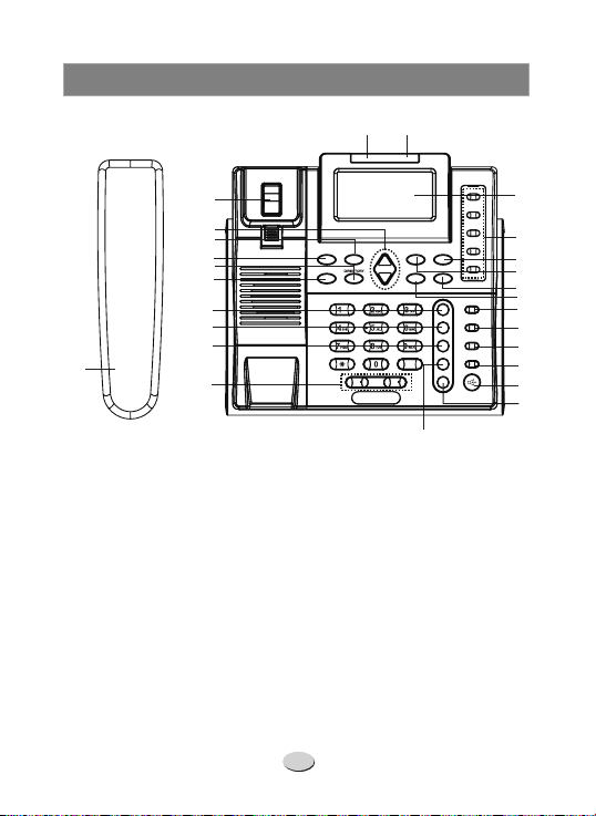
LOCATION OF CONTROLS
22
21
19
18
20
17
16
15
14
26
1. Memory b utto ns ( M1 ~M5)
2. DIAL/ OK b ut ton
3. DELETE button
4. VOICE MAIL button
5. CONFERENCE botton
6. LINE 1 button
7. LIN E 2 bu tton
8. HEADSET button
9. HOLD button
10. S PE AK ER b ut to n
11. REDIAL/P button
12. FL A SH b ut to n
13. Volume controls
14. MUTE butto n
13
23
24
7-10-11
MENU
DELETE
RELEASE
CONFERENCE
VOL.VOL.
12
15. STOR E button
16. SHIFT button
17. MENU button
18. 7-10 -11 bu tt on
19. RELEASE button
20. DIRECTORY button
21. Up & Dow n co nt rols
22. Hook switch
23. New call/24V MESSAGE
indicator
24. Ringer/90V MESSAGE
indicator
25. LCD display
26. Handset
6
VOICE MAIL
M1
25
M2
M3
1
M4
DIAL/OK
SHIFT
STORE
MUTE
FLASH
REDIAL/P
2
M5
3
4
5
6
LINE 1
7
LINE 2
8
HEADSET
9
HOLD
10
SPEAKER
11
Page 9
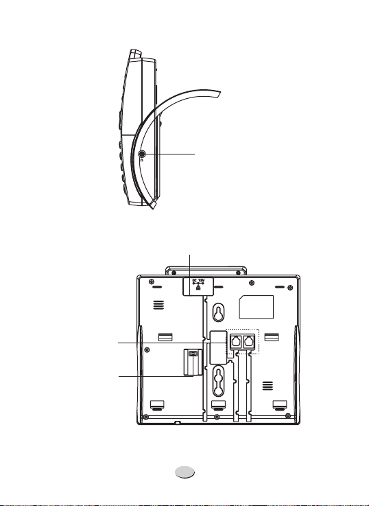
Telephone
line jack
MESSAGE
indicator
switch
Headset jack
Power jack
24V OFF 90V
7
L2/DATA
L1/L2
Page 10

FUNCTION BUTTONS
1.
Receiver or Speaker Volume Control - To adjust the receive
volume in either the handset or speaker, press or .
There are 8 steps of adjustment.
2. Making a call
a. Using handset
1. Pick up the handset, then LINE1 LED will light. If you use LINE2 and
LINE2
press button, thenthe LINE 2 LEDwill light.
2. After you heara dial tone,enter the telephonenumber.
3. To end the call, simplyreplace the handsetin the cradle.
VOL.- VOL.+
b. Using speakerphone
1. Press the button or button, then LINE1 LED will
light. If you use LINE 2, press button, then the LINE2 LED will
light.
2. After you heara dial tone,enter the telephonenumber.
3. To end the call, press the button.
c. Switching a call betweenhandset and speakerphone
During a call with handset, to switchyour call to speakerphone, press
SPEAKER
make or answera call. To switch back, simply lift thehandset.
3. Receiving acall
When a call is received, the phone rings, and LINE1 or LINE2 LED will
flash. Alsothe LCDshows the caller ID number.
If LED flashes, press button or pick up the handset or
LINE1 LINE 1
press button toanswer.
If LED flashes, press button or pick up the handset or
LINE2 LINE 2
press the button to answer.
SPEAKER LINE1
LINE2
SPEAKER
button then hang up the handset. In this mode, you can
SPEAKER
SPEAKER
8
Page 11

4.
Pre-dialling
a. In standby mode, enter the number you want to dial. You can
press button to clearthe incorrect digit.
DELETE
b. If you want to dial out the number through LINE1, press the
or buttonto dial outthe number.
SPEAKER
c. If you want to dial out the number through LINE 2, press
LINE1
LINE2
button to dialout the number.
5. Hold
a. Putting a
During a call, you can press button to put a call on hold, the
LCD will show (X=1~2) then therelevant LED willflash.
call on hold
HOLD
LX HOLDING
b. Cancelling a call onhold
1. When is on hold and is in standby mode, pick up the
LINE1 LINE2
handset or press button to cancelthe call on hold.
2. When is on hold and is in standby mode, pick up the
LINE2 LINE1
handset or press button to cancelthe call on hold.
LINE1
LINE2
6. Switchover between two lines
There are twooperation modes.
1. During a call on LINE1 pressing the button will place LINE 1
on hold and connect LINE2. You may also press the button
first andthen pressthe button.
Line 2
2. During a call on LINE2 pressing the button will place LINE2
on hold and connect LINE1. You may also press the button
first andthen pressthe button.
LINE1
LINE2
HOLD
LINE1
HOLD
9
Page 12

NOTES:
1. After pressing the button, the corresponding line will be
HOLD
placed on hold and the LINE button will blink. The handset can
now be placed on hookwithout disconnecting the line.
2. To continue the conversation, pick up the handset and press the
LINE1 LINE2
or button.
7. Three - way Conference
There are fiveways to establish a three-way conferencecall.
Method 1:
a. Est ablis h a ca ll o n LINE1.
b. Pla ce L IN E1 on hol d.
c. Est ablis h a ca ll o n LINE2 .
d. Press the button.
CONFERENCE
Method 2:
a. Establish a call onLINE2.
b. Pla ce L IN E2 on hol d.
c. Est ablis h a ca ll o n LINE1.
d. Press the button.
CONFERENCE
Method 3:
a. Est ablis h a ca ll o n LINE1.
b. Pla ce L IN E1 on hol d.
c. Est ablis h a ca ll o n LINE2 .
d. Pla ce L IN E2 on Hol d.
e. Press the button
CONFERENCE .
Method 4:
a. W it h a ca ll e sta bl ished on LI NE 1, LINE2 rin gs .
b. Pla ce L IN E1 on hol d.
c. Answer LINE2.
d. Press the button
CONFERENCE .
10
Page 13

Method 5:
a. W it h a ca ll e s ta bl ished o n LI NE 2, LINE 1 ri ng s.
b. Place LINE2 on hold.
c. Answer LINE1.
d. Press the button
CONFERENCE .
8.
1220.The jack is on the right side ofthe phone. Use to take
- A headset with a 2.5 mm plug can be connected to the
Headset
HEADSET
the phone onand of f hook while using theheadset.
9.
- This is used during memory dialing to temporarily pause
Pause
the dialing sequence.
10. Redial Function
a. Go off hook (lift the handset, press or press
HEADSET
)
REDIAL
b. Press (the last dialed number will be dialed).
Enhanced Redial
11.
REDIAL
The button allowsyou to accessthe last 15 dialed numbers.
REDIAL
a. Press (the last dialed number will be displayed)
b. Use to select the desired number.
orst
c. Go off hook (lift the handset, press or press
12.
HEADSET
Flash
).
- Pressing produces an interruption of the line.
FLASH
SPEAKER,
SPEAKER,
This is normally used in conjunction with special features such as
Call Waiting. If you do not have any special features, pressing
may disconnect a call.
FLASH
11
Page 14

13. Mute
- This deactivates the handset, headset or speakerphone
microphone. It allows you to talk without being heardby the distant
party. To use this feature, press .
To deactivate the feature,press again.
MUTE The display will show" ".
MUTE
MUTE
14. Speaker
- This button activates and deactivates the speaker
phone.
15. Delete
- This button is used in various programming actions to
delete items. It is discussed indetail when itis used.
16. Dial/OK
- This button is used in programming to accept a
value and to dial out a displayed number.
17. Menu
18. Directory
19. Voice Mail
- This is discussed in detail in the next section.
- This is discussed in Item 21.
- This dials the number for a voice mail service.
Programming instructions are given in the following section.
12
Page 15

20.
Memory Buttons - The1220 has fiveMemory Buttons ( - ).
M1 M5
Each can store2 telephone numbers.
a. Storing a number Must be done on-hook.
STORE
i. Press .
ii. Dial the number to be stored.
STORE
iii. Press .
iv. Enter the name to be stored and press . Press
STORE
v. Use to select the ring cadence for this number.
vi. Press .
if you do not wish to enter a name.
or
st
STORE
STORE
vii. Press the desired Memory Button. You may store an
additional number in this location by pressing and
SHIFT
then pressing the Memory Button.
b. Editing a number It is not possible to edit a number. Simply
store another number in this location.
c. Reviewing a number While on-hook, press the desired
Memory Button to display the stored number. If no number
is stored, the display will say " ".
MEMORY IS EMPTY
d. Dialing a Number
i. Go off hook (lift the handset, press , or press
HEADSET
)
SPEAKER
ii. Press the desired Memory Button
e. Storing a Caller ID Record.
i. While on-hook, press until the desired number is
or
st
displayed.
ii. Press and hold until the last digit begins to flash.
iii. Press two times.
iv. Use to select the ring cadence for this number.
st
STORE
v. Press .
STORE
STORE
or
vi. Press the desired Memory Button.
13
Page 16

21. Directory - Up to names and numbers may be stored in
70
the Directory.
a. Storing a number Must be done on-hook.
i. Press . The display will say .
MENU DIRECTORY
ii. Press . The display will say . Press
DIAL/OK REVIEW
until the display says .
iii. Press .
DIAL/OK
ADD
st
iv. Dial the number to be stored up to 20 digits.
v. Press .
DIAL/OK
vi. Enter the name to be stored and press . Press
DIAL/OK
vii. Use to select the ring cadence for this number.
viii. Press .
ix. Press to exit.
if you do not wish to enter a name.
or
st
DIAL/OK
DELETE
DIAL/OK
b. Editing a number - It is not possible to edit a number. Simply
store another number in this location.
c.
Reviewing a number - Must be done on-hook.
DIRECTORY.
i. Press The first directory entry will be shown.
st
ii. Press or to see the other entries.
iii. If the number is more than 13 digits an arrow will show on
the display. Press or to see the rest of the number.
st
d. Dialing a Number
i. Press The first directory entry will be shown.
DIRECTORY.
ii. Press until the desired entry is shown.
iii. Go off hook (lift the handset, press or press
or
st
). The number will be dialed.
HEADSET
SPEAKER,
or
14
Page 17

e. Storing a Caller ID Record.
or
i. While on-hook, press until the desired number is
st
displayed.
ii. Press and hold until the last digit begins to
DIRECTORY
flash.
DIAL/OK
iii. Press two times.
iv. Use to select the ring cadence for this number.
v. Press . Display shows .
vi. Press two times.
or
st
DIAL/OK SAVE OK
DIAL/OK
f. Storing a dialed number. Any of the last 15 dialed numbers
may be stored into the directory.
REDIAL
i. Press .
ii. Press until the desired entry is shown.
iii. Press and hold until the last digit begins to
or
st
DIRECTORY
flash.
iv. Press two times.
DIAL/OK
v. Use to select the ring cadence for this number.
vi. Press . Display shows SAVE OK.
vii. Press two times.
or
st
DIAL/OK
DIAL/OK
g. Deleting a number.
i. Press .
DIRECTORY
ii. Use until the number is shown on the display.
iii. Press once.
iv. Press again to confirm.
or
st
DELETE
DELETE
15
Page 18

22.
7-10-11
- This button changes the format of the displayed
number. Three formats are available:
7-Digit 7 Digit Telephone Number
10-Digit 3 Digit Area Code + 7 Digit Telephone Number
11-Digit 1 Digit Long Distance Code + 3 Digit Area Code + 7 Digit
Telephone Number
Example: Assume the local area code is 662 and a 7 digit local
number is displayed 555-1212.
Pressing the 7-10-11 button once will display the number plus area
code: 662-555-1212.
Pressing the 7-10-11 button again will add the LDS code (usually 1):
1662-555-1212
Pressing the 7-10-11 button again will show the 7 digit number:
555-1212
Note:
This assumes that an LDS code has been programmed into
the telephone.
23.
Release
- To end a conversation, press once. The
RELEASE
phone willgo on-hookfor 1.5 seconds and then go off hookagain to
allow another callto be made.
24.
Message Waiting/New Call Lamp
- This lamp above thedisplay
will light to indicate a voice mail message. The 1220 is compatible
with four types of message waiting: 90V, 24V, Frequency Shift Keying
(FSK) and Stutter Dial Tone (SDT). Contact your telephone service
provider to determine the type of message waiting. For 90V or 24V
of message waiting is selected with a switchunderneath the
the type
phone. FSK message waiting will be detected automatically. SDT
message waiting must be activated in the menu. For these types of
message waiting, the switch should be in the OFF
position. If the
phone is connected directly to a telephone line, the switch shouldbe
in the OFF position. This lamp will flash to indicate a new call. To
stop the flashing use the to review thecalls.
orst
16
Page 19

MENU SETTINGS
Many of the settings of the phone are controlled from the menu.
To access the menu, press while the phone is on-hook.
The various menu settings are discussed in detail below.
MENU
1. Directory
2. Factory Reset
press to confirm. This will restore the phone to the original
settings. All memory and CIDrecords will belost.
3. Pause Time
value. Use to adjust the time. This can be adjusted in 100
mSec intervals from 1 to 5 sec
Press to confirm.DIAL/OK
4. Ringer Suppress
after Caller ID is displayed. The first ring will be suppressed. To
select this feature, press and then use to toggle
between OFF andON. Press to confirm.
5. Voice Mail
voice mail. This number will be dialed when the button
is pressed.
a. When is displayed, press .
b. Press .
c. Enter the phone number for your voice mail.
d. Press .
e. Press . will be displayed.
f. Press .
g. Enter the password (PIN) for your voice mail.
h. Press .
i. Press . will be displayed.
j. Press .
- This is covered
DIAL/OK
NUMBER
- When this is displayed, press and then
- Press to display the current pause time
ororst
- This allows you to enter a number to access your
VOICE MAIL DIAL/OK VOICE
will be displayed.
DIAL/OK
DIAL/OK
DOWN VM PASSWORD
DIAL/OK
DIAL/OK
t
# 3 SEC PAUSES
DIAL/OK
in the previoussection.
DIAL/OK
DIAL/OK
onds(3600 mSec is the default value).
- If this is selected, the phone will not ring until
DIAL/OK
DIAL/OK
17
st
VOICE MAIL
Page 20

k. Enter the number of 3 second pauses to be inserted between
dialing the voice mail number and the PIN. For example, if
you enter 2 here, the phone will pause 6 seconds.
DIAL/OK
l. Press .
m. Lift the handset to end programming.
6. Set SDT
- The 1220 can respond to Stutter Dial Tone Message
Waiting. If this is set to ON, the phone will go off hook briefly
after every call to check the dial tone. If it is stuttered, the
message lamp will be lit. To select this feature, press
or
and then use to toggle between OFF and ON. Press
DIAL/OK
7. Hold Mode
In Normal mode, the button will place the phone on local
st
to confirm.
- The 1220 has two hold modes: NORMAL and PBX.
HOLD
DIAL/OK
hold. This call can be retrieved from any phone connected to the
line. In PBX mode, the button can be programmed to dial a
HOLD
code to place the call on PBX hold. Please note there is no hold
indication in PBX mode. To select this feature, press and
or
st
then use to toggle between NORMAL and PBX. Press
DIAL/OK
8. Select Line 1/2
to confirm.
- This selects the default line when the phone
DIAL/OK
goes off hook.
or
st
b. Press to select or .
DIAL/OK
c. Press to confirm.
9. Set Access Code
L-1 L-2
- This is a number that is dialed to access an
outside line when the phone is used behind a PBX.
DIAL/OK
a. Press .
b. Dial the access code (up to 4 digits).
DIAL/OK
c. Press to confirm.
d. Press to continue with programming.
or
st
18
12
Page 21

10. Date Format
date. To select this feature, press and then use
- This selects the format used to display the
DIAL/OK
st
or
to toggle between MM-DD (Month-Day) and DD-MM (Day-Month).
DIAL/OK
Press to confirm.
11. Hour Format
time. To select this feature, press and then use
to toggle between 12 hour and 24 hour format. Press to
- This selects the format used to display the
DIAL/OK
st
DIAL/OK
or
confirm.
12. Set Flash
select this feature, press and then use to toggle
- This selects the length of time for the flash. To
DIAL/OK
st
or
between 600mSec, 300mSec, 120mSec, and 100mSec. Press
DIAL/OK
to confirm. Note that 600mSec is the standard time for
North America.
13. Set Area and LDS
- This sets the local area code and the
code used to dial a long distance number. These values are used
in conjunction with the 7-10-11 button.
DIAL/OK
a. Press .
b. Enter the area code using the keypad. Do not press
DIAL/OK
.
c. Enter the LDS code. This is 1 for North America.
d. Press .
DIAL/OK
e. Press to move to the next item.
st
or
14. Set Language
Spanish. To select this feature, press and then use
t
to select a language. Press to confirm.
15. Set Time and Date
- The 1220 supports English, French and
DIAL/OK
DIAL/OK
- This allows manual entry of the date
s
and time. Please note that Caller ID will set these values. If you
have CID service, skip this step.
19
or
Page 22

DIAL/OK
a. Press .
b. E
nter the time and date using the keypad. The time must be
entered in 24 hour format. The setting sequence is hour,
minute, month, day, and year. Use the * key to delete any
incorrect values. After setting the year, the day of the week
will be set automatically.
DELETE
c. Press to exit.
16. LCD Contrast
(Lightest) to 4 (Darkest). To select this feature, press
and then use to select a contrast value. Press
- There are four values of LCD contrast from 1
DIAL/OK
orst
DIAL/OK
to confirm.
17. Set Ring
- The 1220 has 10 ringer cadences and 4 ringer
volumes plus OFF.
a. Press . Display says .
DIAL/OK RING TYPE L1
b. Press . The phone will ring with the selected ring
DIAL/OK
type.
c. Use or to select a ring type.
st
d. Press .
DIAL/OK
e. Press . Display says
s
f. Press .
DIAL/OK
g. Use or to select a ring volume.
st
h. Press .
DIAL/OK
I. Press . Display says
s
j. Press The ph on e wi ll ring wit h th e se le cted
DIAL/OK.
RING VOLUME L1.
RI NG T YPE L2 .
ring type.
k. U se or to se le ct a r ing type.
st
l. Press
DIAL/OK.
m. Press . Display says
n. Press
o. Use or to select a r in g vo lu me.
p. Press
q. Press twice to exit.
s
DIAL/OK.
st
DIAL/OK.
DELETE
RI NG V OLUME L 2.
20
12
Page 23

CALLER ID INFORMATION
A caller ID record consists of the following information:
Time and Date
Caller's Name and Number
* Note that this feature requires caller ID service from your telephone
company.
DISPLAY MESSAGES
msg
REPEAT
In addition to the Message Waiting light, an icon will appear in the
display whenever there are messages. This icon is " ". It will
MSG
remain until all messages have been cleared. The display will also
show MESSAGE WAITING at the bottom if there is a message. Note
that this requires voice mail service from a service provider.
21
Page 24

TOTAL and NEW CALLS
- The total calls are
displayed at the bottom of the screen. New
calls are displayedat the topright.
- If a caller has prevented his name
PRIVATE
and number from being sent, the display
will show .
PRIVATE
- If a number calls more than once,
REPEAT
will appear in the upper right ofthe
REPEAT
screen.
9:52 9/12
TOTAL 04 MON
9:52 9/12
PRIVATE
9:52 9/12
12274612345
NEW
02
CALL #
03
CALL #
03
REPEAT
END OF LIST
- This message is displayed
when the end of the CID list has been
reached with the or arrow.
OUT OF AREA
st
- This message will display
when a call is received from an area which
is not providingcaller ID information.
22
9:52 9/12
END OF LIST
9:52 9/12
CALL #
OUT OF AREA
04
Page 25

CALLER ID SYSTEM OPERATION
Note that a subscription to caller ID service is required.
New call indicator NEW
have been reviewed.
Review Call Records
records. If the number is longer than 13 digits, an arrow will show in
the rightcorner of the LCD.Use or to show the other digits. Use
st
or again to move to the next record. Records may be reviewed
quickly by holding or for approximately 3 seconds. At the endof
the records, thedisplay will show .
Save Call Records
oldest record to make room for new calls. Save specific calls by
deleting unnecessary call records.
Delete Single Numbers or All Records -
to select the number to be deleted. Press . The LCD will show
. Press again to confirm. To delete all records, press
DELETE ? DELETE
and hold for 6 seconds. The LCD will show .
Press to confirm.
Call Back from Caller ID
Off-Hook
1.Go off-hook.
2. Use or to select the number to be called.
3. Use to modify thenumber format ifnecessary.
4. Press .
DELETE ALL DELETE ?
DELETE
st
7-10-11
DIAL/OK
- The display will show until all new calls
st
- Use or to scroll through the caller ID
st
st
- The phone stores 50 CID records. It drops the
END OF LIST
While on-hook use or
DELETE
23
st
Page 26

On-Hook
st
1.Use or to select the number to be called.
2. Use to modify thenumber format ifnecessary.
7-10-11
3. Press .
DIAL/OK
24
Page 27

CALLER ID ON CALL WAITING
When you subscribe to this feature from the telephone company,
the LCD will display the name and number of a second caller
while you are on a call.
Caller ID info displayed
Caller 1
436-1234
Use the button to answer the second call.
FLASH
Use the button again to return to the first call.
FLASH
Caller two's information
is displayed
Caller 1
4
Caller 2
291-5678
25
Page 28

If you have problems with your phone, please check below
for helpful hints:
BLANK OR
FAINT
SCREEN
CALLER ID
DOES NOT
WORK
PHONE
WILL NOT
RING
NO DIAL
TONE
NO CHARACTERS
ON DISPLAY
TROUBLESHOOTING
l
Check line cordand adapter.
l
Check Contrast setting.
l
Be sure yourcaller ID service is active.
l
Do not answerthe phone beforetwo rings.
l
If the problem continues, contact the telephone
company.
l
Be sure theringer is notoff.
l
There may be too many devices connected to the
phone line. Remove all other phonesand see if this
phone will ring. If so, add devices back one by one
to find theproblem unit.
l
Verify that theline cord is connected.
l
Verify that the line cord connection is correct and
tightly secured.
l
Check power adapter.
26
Page 29

DO NOT ATTEMPT TO REPAIR THIS PRODUCT YOURSELF.
TELEPHONE REPAIR
Telephones manufactured by CORTELCO must be returned to us
for repair. You can return your telephone to CORTELCO for repair
or replacement in accordance with our LIMITED WARRANTY.
CORTELCO warrants THIS PRODUCT against defects in material and
workmanship in accordance with our LIMITED WARRANTY. If your
telephone is returned for repair, include a copy of your sales
receipt containing the date-of-purchase. DO NOT INCLUDE THE
ORIGINAL SALES RECEIPT. If date of purchase is not included, the
factory date printed on the label on the bottom of your telephone
will be used as the date of purchase. The factory date allows six
months for distribution and sale of this product. If you return
your telephone for repair, the warranty period is not extended.
The original date of purchase continues to apply to your warranty.
We will repair this product for a nominal fee after the LIMITED
WARRANTY has expired if you send it to us in a complete and
undamaged condition. The repaired unit will be shipped to you
C.O.D., freight collect. If you are returning a unit to us for repair,
package it carefully, preferably in the original carton. Be sure to
include your return address, a copy of the sales receipt showing
date-of-purchase, and a note describing the problem you have
with your telephone. Shipping must be prepaid. If the telephone
is in warranty, it will be repaired or replaced, at our option, at no
cost to you, and it will be returned shipping prepaid. Ship your
telephone (shipping prepaid) to:
CORTELCO
REPAIR CENTER
1703 SAWYER ROAD
CORINTH, MS 38834
Page 30

If you purchased this product new in the U.S. or Puerto Rico,
LIMITED WARRANTY
CORTELCO warrants it against defects in material and
workmanship for a period of two years from the date of original
purchase. This warranty is in lieu of all other express warranties.
During the warranty period, CORTELCO agrees to repair or, at its
option, replace the defective product, or any part of it without
charge for parts or labor. This is your exclusive remedy. This
warranty does not cover damage resulting from accident, misuse,
abuse, improper installation or operation, lack of reasonable care,
the affixing of any attachment not provided by CORTELCO with the
product and loss of parts. The warranty is voided in the event any
unauthorized person alters or repairs the unit. Telephone
companies use different types of equipment and offer various
types of services to customers. CORTELCO does not warrant that
this product is compatible with the type of equipment of any
particular phone company or the services provided by it.
CORTELCO DISCLAIMS ANY IMPLIED WARRANTY, INCLUDING THE
WARRANTY OF MERCHANTABILIT Y AND THE WARRANTY OF FITNESS
FOR A PARTICULAR PURPOSE, AS OF THE DATE TWO YEARS FROM
THE ORIGINAL PURCHASE OF THE PRODUCT. CORTELCO ASSUMES
NO RESPONSIBILITY FOR ANY SPECIAL, INCIDENTAL OR
CONSEQUENTIAL DAMAGES. THIS WARRANTY GIVES YOU SPECIFIC
LEGAL RIGHTS, AND YOU MAY HAVE OTHER RIGHTS WHICH VARY
FROM STATE TO STATE. SOME STATES DO NOT ALLOW THE
EXCLUSION OR LIMITATION OF SPECIAL, INCIDENTAL OR
CONSEQUENTIAL DAMAGES OR LIMITATIONS ON HOW LONG AN
IMPLIED WARRANTY LASTS, SO THE ABOVE EXCLUSION AND
LIMITATION MAY NOT APPLY TO YOU.
If failure occurs and your telephone is in warranty, service shall be
provided by returning it to CORTELCO - Repair Center, 1703 Sawyer
Road, Corinth, Mississippi 38834, shipping prepaid. The product
will be repaired or replaced if examination by us determines the
product to be defective. Telephones received damaged as a
result of shipping will require you to file a claim with the carrier.
Page 31

Part 68 is a Federal regulation which requires equipment to be
FCC INFORMATION
tested and registered with the FCC prior to its connection to the
network. This equipment complies with Part 68 of FCC rules. On
the bottom of the telephone is a label that contains, among other
information, the FCC Registration Number and the Ringer
Equivalence Number (REN) for this equipment. You must, upon
request, provide this information to your telephone company.
The Ringer Equivalence Number (REN), which is used to
determine the number of devices you may connect to your phone
line, indicates the amount of power that your telephone draws
from the telephone company line during ringing. If you have
more than one telephone (or other terminal device) connected to
the telephone company line, you should total the RENs, and be
sure that the total is not more than five. Your telephones may not
ring if the total is more than five. Also, in some rural locations,
your telephone may not ring if the REN total is more than three.
RESTRICTIONS
operated lines or party lines.
INSTALLATION
telephone company lines through a modular jack. The required
USOC for the modular jack is RJ11C for desk mounting and RJ11W
for wall mounting. The USOC number is printed on the label on
the bottom of your telephone.
HEARING-AID COMPATIBILITY
work with magnetically-coupled hearing aids. You can use a
hearing aid equipped with a T (Telephone) switch.
IN CASE OF TROUBLE
on the telephone line, the telephone company can temporarily
disconnect your service. The telephone company must then notify
and allow you to correct the problem. The telephone company
may from time to time change its lines or equipment. They must
notify you if planned changes will affect your telephone service,
to allow you to take steps to prevent interruptions.
This telephone complies with Part 15 of the FCC Rules. In the
unlikely event that interference occurs, move the telephone
and/or radio, television, etc. to increase the separation distance.
You must not connect your telephone to coin
This model telephone must be connected to the
The handset on your telephone will
If your telephone should cause problems
 Loading...