

Page 1

Table of Contents
INTRODUCTION ........................................................................................................................................5
Datalog 3 ........................................................................................................................................5
Operation Overview........................................................................................................................5
A Zone
Input Type...............................................................................................................................7
Alarm type ..............................................................................................................................8
Icon Types..............................................................................................................................8
Alarm Help Text......................................................................................................................8
Input Group.............................................................................................................................8
Output Group..........................................................................................................................8
Priority Number ......................................................................................................................9
Zone Enable ...................................................................................................................................9
Zone Inhibit.....................................................................................................................................9
THE MAIN SCREEN.................................................................................................................................11
Last Events Window.............................................................................................................11
Status Window .....................................................................................................................12
Accept Button .................................................................................................................................12
Reset Button...................................................................................................................................12
Event Help Button...........................................................................................................................12
Map Viewer Button .........................................................................................................................13
Log On Button.................................................................................................................................13
Zone Inhibit Button..........................................................................................................................13
Group Inhibit Button........................................................................................................................13
Additional Buttons...........................................................................................................................13
Map Icons .......................................................................................................................................13
Blue Icon...............................................................................................................................13
Green Icon............................................................................................................................14
Grey Icon..............................................................................................................................14
Maroon Icon..........................................................................................................................14
Red Icon...............................................................................................................................14
Yellow Icon...........................................................................................................................14
HANDLING ALARM EVENTS .................................................................................................................15
Alarm Cause Dialog Box ................................................................................................................15
The Alarm Queue ...........................................................................................................................16
Multiple Alarms ...............................................................................................................................17
Alarm Logging.................................................................................................................................18
INHIBITING ZONES .................................................................................................................................19
Single Zone Inhibit..........................................................................................................................19
Single Zone Enable ........................................................................................................................19
Zone Inhibit Screen.........................................................................................................................20
Zone Inhibit List....................................................................................................................20
Group Inhibit ...................................................................................................................................21
Group Enable..................................................................................................................................21
Datalog 3 User Manual - Page 1 of 66
CORTECH DEVELOPMENTS LTD
Downloaded from: http://www.guardianalarms.net
Page 2

Group Inhibit List.............................................................................................................................21
Zone Inhibit Timer...........................................................................................................................22
OUTPUT CONTROL ................................................................................................................................24
Alarm Operated Output ..................................................................................................................24
Manual Output Control....................................................................................................................24
Time Zone Operated Output Control..............................................................................................25
TIME ZONES............................................................................................................................................26
Time Zone Form.............................................................................................................................26
Time Zone Description .........................................................................................................26
Time Zone Time On .............................................................................................................27
Time Zone Time Off .............................................................................................................27
Time Zone Monday-Sunday.................................................................................................27
Time Zone Action List...........................................................................................................27
Time Zone Group List...........................................................................................................27
Adding a New Time Zone...............................................................................................................28
Editing a Time Zone........................................................................................................................28
Displaying a Time Zone..................................................................................................................29
Deleting a Time Zone .....................................................................................................................29
MAP VIEWER........................................................................................................................................... 30
Map Selection Box..........................................................................................................................30
Icon Display ....................................................................................................................................30
Map Viewer Options .......................................................................................................................31
Map Viewer Walk Test Options ......................................................................................................31
WALK TEST.............................................................................................................................................32
Omit Zones from Walk Test............................................................................................................32
Re-instate Walk Test Zone.............................................................................................................32
SYSTEM USERS AND PASSWORDS ....................................................................................................33
A Password.....................................................................................................................................33
Master Password Setup Screen.....................................................................................................33
Master Password User List ..................................................................................................34
Master Password Name Field ..............................................................................................34
Master Password Title Field.................................................................................................34
Master Password Field.........................................................................................................34
Master Password Days to Expiry Field ................................................................................35
Master Password User Access Level...................................................................................35
Adding a New User and Password.................................................................................................35
Editing an Existing User and Password..........................................................................................35
Displaying Users and Password.....................................................................................................36
Deleting a User and Password.......................................................................................................36
Changing Your Password...............................................................................................................36
USER SETUP...........................................................................................................................................38
Time Setting....................................................................................................................................38
Date Setting....................................................................................................................................39
Setup Automatic Time Zones Button..............................................................................................40
Datalog 3 User Manual - Page 2 of 66
CORTECH DEVELOPMENTS LTD
Page 3

Show Dynamic Display...................................................................................................................40
Enter Alarm Cause .........................................................................................................................40
Password to Accept an Alarm ........................................................................................................40
Follow Latest Alarm........................................................................................................................40
Task Bar Enabled ...........................................................................................................................41
Show Zone Numbers......................................................................................................................41
Timed Alarm Analysis Printout .......................................................................................................41
Password Expiry Warning ..............................................................................................................41
Logging Printer ...............................................................................................................................42
Virtual Walk Test Thresholds..........................................................................................................42
User Setup Additional Buttons ........................................................................................................42
REPORTS.................................................................................................................................................43
Report Button Bar...........................................................................................................................43
Report 100% Button.............................................................................................................43
Report Zoom In Button.........................................................................................................43
Report Zoom Out Button ......................................................................................................43
Report Go To Start Button....................................................................................................43
Report Previous Page Button...............................................................................................43
Report Page Status Window................................................................................................43
Report Next Page Button .....................................................................................................43
Report Go To End Button..................................................................................................... 43
Report Printer Setup Button.................................................................................................44
Report Print Button...............................................................................................................44
Alarm Analysis Report ....................................................................................................................44
Alarm Analysis Report View Worst Case Alarms................................................................. 45
Report Zones Selection........................................................................................................ 45
Database History Report ................................................................................................................45
Report From Date.................................................................................................................47
Report To Date.....................................................................................................................47
Alarm Database Report From Time .....................................................................................47
Alarm Database Report To Time.......................................................................................... 47
Alarm Database Report Event Field..................................................................................... 48
Alarm Database Report User Field ......................................................................................48
Alarm Database Report Alarm Event...................................................................................48
Alarm Database Report Options Field .................................................................................48
Time Zone Report...........................................................................................................................49
User Report ....................................................................................................................................49
Walk Test Report............................................................................................................................49
EVENT REGISTER...................................................................................................................................51
Viewing the Event Register ............................................................................................................51
ALARM SOUNDS.....................................................................................................................................53
Assigning Alarm Sounds ................................................................................................................53
Generating Alarm Sounds ..............................................................................................................54
ENGINEER SETUP ..................................................................................................................................55
Putting a zone on Soak ..................................................................................................................56
Removing a Zone from Soak Test..................................................................................................56
Disabling a Zone.............................................................................................................................56
Datalog 3 User Manual - Page 3 of 66
CORTECH DEVELOPMENTS LTD
Page 4

Re-instating a Disabled Zone.........................................................................................................56
MODEM SUPPORT..................................................................................................................................57
QUITTING DATALOG 3...........................................................................................................................59
CORTECH DEVELOPMENTS.................................................................................................................61
Contacting Cortech Developments.................................................................................................62
Datalog 3 User Manual - Page 4 of 66
CORTECH DEVELOPMENTS LTD
Page 5

Introduction
Datalog
The Datalog 3 software program was written to operate on a PentiumTM or compatible PC using the
Windows95
The software includes an easy to use operator interf ace, high definition gra phics, sophisticated alar m
database and access control com patibility. T he operator interf ace is identical ac ross a wide platfor m of
different manufacturers input hardware.
The
Datalog 3
TM
operating system. The PC requires a sound card to give audible annunciation of alarms.
run time software relies on the following files: i. Maps/drawings produced in BMP format, using a drawing package.
ii. Text help files produced using any ASCII text editor.
iii. The set-up files produced with the Datalog 3 'Editor' program.
iv. Sound files in ‘Wav’ format
3
Operation Overview
The centre of operation for the Datalog 3 system is the main screen window.
The main screen is displayed at system start up. It contains a number of control buttons for the system,
which are enabled and disabled as required. In normal operation the map window contains the main site
map. The operator is returned to this screen after alarms have been accepted and reset.
Any input transmitted to the Datalog system from input hardware such as alarm panels would be defined
on the system as a zone.
Should the input change state and cause an alarm on the system, the main screen’s map will change to
a map relevant to the area of the alarm and an icon will flash to flag the alarm position. Below the map
the alarm queue will display showing the date, time, and description of the alarm.
In addition the Datalog system can activate output relays when the zone goes in to alarm, If outputs
have been assigned to the zone by the installer at set-up.
The operator of the Datalog system will need to accept receipt of the alarm. Once the alarm resets and
the cause is known, the Datalog can be reset, with an option to add cause text to the alarm history log.
The alarm activation, reset and cause information are all time stamped and stored in log files, along with
the User name of the operator currently signed on. The log files can be reviewed and analysed in the
form of reports.
Much of the set-up programming of the system is performed at installation time. This includes:
Map definition and assignm ent
Zone set-up – Descriptions, input types, alarm types, positioning on maps
Zone groups – Grouping zones to simplify inhibiting.
Output groups – assigning output relays to groups and linking to activating zones
Help text – Help text can be written for alarm conditions and assigned to the zone.
Password protected menu options allow the operator to perform functions such as:
Inhibiting zones
Inhibiting Zone Groups
Manually switching outputs
Setting Time Zones
Setting Passwords
Zone Group Inhibits and Output Group switching can be timed using a timezone.
Datalog 3 User Manual - Page 5 of 66
CORTECH DEVELOPMENTS LTD
Page 6

Datalog 3 User Manual - Page 6 of 66
CORTECH DEVELOPMENTS LTD
Page 7

A Zone
A zone on the Datalog system is any sensor(s) on a site that are linked to a single input point on a field
panel. Types of sensor include: door contacts, passive infra-red sensors (PIR), Guardwire zones, panel
cabinet tampers etc.
Two sensors on double-leaf doors could be wired to the panel as two separate inputs and therefore two
separate zones, or wired in series to a single input as 1 zone.
A zone is normally enabled so that any activation of the zone’s sensor will generate an alarm and/or
may cause one or more relays to energise. However a zone can be inhibited so that an alarm is not
generated when the sensor is activated and any relays assigned will not be energised.
A zone has a number of attributes. The equipment provider at installation sets these up.
The attributes include:
A text description
An input type
An alarm type
An icon type
A position on up to 3 maps
Alarm help text.
An input group
An output group
A priority number (0-255, 255 is highest priority)
Input Type
The input type options are:
Normally Open Normally Open allows the input to be configured for use with
normally open devices.
Normally Closed Normally Closed allows the input to be configured for use with
normally closed devices.
Non-existent Any unused inputs within the Datalog system are normally set to
non-existent.
Normally Open Auto-enable
Normally Closed Auto-enable
In addition to an input being Normally Open or Normally Closed, the input can have an auto-enable
feature.
Each zone has an inhibit timer that can be set to enable the zone after a predetermined number of
minutes. The zone remains inhibited even if the zone is returned to a secure state until the timer expires.
This timed inhibit feature can be further enhanced by setting zones as 'auto-enable'. This is done using
the INPUT TYPE setting. If the auto-enable feature is ON for a zone, then the zone will auto-enable
when the inhibit timer expires, as before. The difference is that if a zone should reset before the timer
expires then the zone will auto-enable. E.g., a magnetic contact on a roller shutter door is set with auto
enable ON, and the inhibit timer is set to five minutes. The roller shutter zone will remain inhibited until
either the roller shutter is closed, securing the zone, OR the inhibit timer reaches zero after five minutes.
This 'auto enable' feature should only be used on stable state sensors, not on movement detectors such
as PIRs.
Datalog 3 User Manual - Page 7 of 66
CORTECH DEVELOPMENTS LTD
Page 8

Alarm type
The Datalog alarm type sets the behaviour of the input for different conditions:
Printer Only: An activated input causes no change on the Datalog screen and requires no operator
action. However, the activity will be recorded on the printer and logged to disk with time
and date.
Normal: This is the usual setting for all inputs, they are shown on screen, require operator
action and are recorded.
High Priority: This would be used for all emergency or similar type inputs. When an input of this type
is activated, all other pending alarms are cleared, and only other high priority inputs are
displayed. Gives the alarm a priority number of 255.
24Hour Tamper: This type of input cannot be inhibited using the access terminal screen and
should be used as a 24-hour loop circuit. When input hardware other than the Datalog
hardware is used, then the input devices may automatically handle tampers.
Technical: When selected this input will be used for technical input/output and cannot be inhibited.
Relay output groups can be controlled by the input condition (this type of event is not
logged). In addition by setting the input group as required, then the input group state
will follow the state of the technical input.
P.A. Button: Personal Attack circuit. Behaves as 24 hour tamper, but custom software applications
may use this type to cause a dial out to a central station.
Silent P.A.: Behaves as a Printer Only alarm as above but cannot be inhibited. Custom software
applications may use this type to cause a dial out to a central station.
Icon Types
The Datalog 3 system provides 40 different icons to differentiate between types of alarm.
Alarm Help Text
These are text files created to give instructions for a particular zone. It is possible to allocate different
text files to zones.
Input Group
The Datalog 3 system allows up to 100 different input groups to be defined on the system. A zone can
be assigned to an input group. Many zones can be assigned to the same group, but a zone can only
belong to one input group.
Zones are placed in groups to allow specific areas of the security system to be inhibited or activated
either manually or on a timed basis via a time zone.
Output Group
The Datalog 3 system allows up to 100 output groups to be defined and set-up on the system. Each
output group can contain 1 or more output relays.
One output group can be assigned to a zone. If an output group is assigned to a zone, then when that
zone is activated the outputs will energise, when the alarm is reset on the Datalog 3 system the outputs
will de-energise.
Datalog 3 User Manual - Page 8 of 66
CORTECH DEVELOPMENTS LTD
Page 9

Priority Number
A priority number can be assigned to an alarm. The number is between 1 and 256, where 1 is the
highest priority and 256 is the lowest. This priority number is displayed in the alarm queue so the
operator can pick the most urgent alarms to deal with if several are reported at the same time.
Zone Enable
When a zone is enabled, its action is dependent on the alarm type. For most zones, should the zone’s
sensor activate it will cause the Datalog System to generate an alarm. If the zone is a technical type it
will activate an Output Group energising 1 or more relays.
Zone Inhibit
Individual inputs can be inhibite d for m aintenance / repa ir , or where it is inco nv en ient to ha ve the alarms
constantly activated i.e. in frequ ent l y used areas. When a zone is inhibited, should the zone ’s sens or
activate, the Datalog System will not generate an alarm or log the event in the database.
When a zone is inhibited, maps will display a yellow icon to denote the status.
On most systems, when the zone is inhibited and its sensor is activated, maps will display a red icon to
show the status. However some systems may have a software option to inhibit the zone in the alarm
panel in addition to the Datalog zone in which case the icon will remain yellow while in inhibit mode and
not change to red.
Certain zones will not allow inhib it ing, these are '24 Hour ' zone types.
Zones can be inhibited:
Individually by manual operation, using ‘Single Zone Inhibit’
In groups by manual operation, using ‘Group Inhibit’
In groups on a timer, using ‘Time Zones’
Individually on a timer, using the ‘Inhibit Timer’
Datalog 3 User Manual - Page 9 of 66
CORTECH DEVELOPMENTS LTD
Page 10

Datalog 3 User Manual - Page 10 of 66
CORTECH DEVELOPMENTS LTD
Page 11
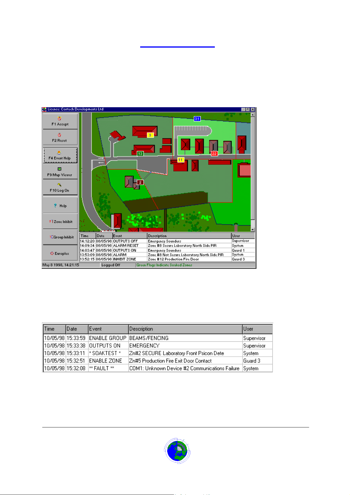
The Main Screen
The centre of operation for the Datalog 3 system is the main screen window.
The main screen is displayed at system start up. It contains a number of control buttons for the system,
which are enabled and disabled as required.
In normal operation the map window contains the main site map. The operator is returned to this screen
after alarms have been accepted and reset, also on closing the menu panel.
Click on the relevant area of the Main Screen graphic below for more help.
Last Events Window
The last events window is the area below the site map on the main screen when in normal operation i.e.
no alarms to accept or reset. It will contain the Date, Time, Event, Description and User’s name for the
last 5 events that have occurred on the system.
Each line displayed is very similar to the information recorded on the hard disk in the system history log.
Datalog 3 User Manual - Page 11 of 66
CORTECH DEVELOPMENTS LTD
Page 12
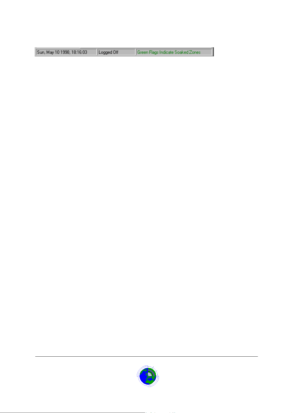
Status Window
The Status Window is at the bottom of the main screen.
It contains three panes, from left to right: -
1. Displays the current system date and time.
2. Displays whether an operator is Logged On or Off.
3. Displays text either for general information or to inform the operator as to a course of action
to take.
Accept Button
The Accept Button is clicked or the F1 key is pressed, in order to accept receipt of one or more alarms
that have been generated.
If an option ‘Password to Accept an Alarm’ has been selected, the operator will be prompted to enter
his/her password before the system can proceed with accepting the alarm(s).
Once the alarm(s) have been accepted the alarm’s warning sounds will cease and the screen map will
zoom to view 2 (if a further zoom view has been allocated). The alarm icon will stop flashing on/off and
the icon border will pulse.
The cause of the incident can now be investigated. A beep will occur about every 10 seconds and a
message is displayed in the status window “Waiting for Reset, Press F2”.
Once the cause is established the operator should either click the Reset button or press the F2 key to
reset the alarm.
Reset Button
The Reset Button is clicked or the F2 key is pressed, in order to reset one or more alarms whose cause
is known. If the alarm condition has cleared then the system will reset and any outputs set by the alarm
will now be de-energised. The system will return to normal operation showing the main site plan.
If an option ‘Enter Alarm Cause’ has been selected, an Alarm Cause dialog box will request an operator
comment on the cause of the alarm.
The operator has two choices for entering a cause:
1. Use one of the pre-defined causes by clicking on the relevant button or typing the
underscored letter on the button.
2. Press the Tab key or click in the text box at the bottom of the dialog box and enter a
description of the cause.
Once the cause has been entered the alarm condition will reset and any outputs set by the alarm will
now be de-energised. The system will return to normal operation showing the main site plan.
Event Help Button
The event help button on the main screen (or pressing F4 function key) allows an operator to call up
specific help text for an alarm after it has been accepted and before it is reset. This text could be
procedures to follow when that alarm occurs, or contact phone numbers.
If more than one alarm is pending reset then the relevant alarm should be selected using the mouse or
up/down arrow keys before clicking the event help button (or pressing the F4 function key) in order to
display the help for that alarm.
If this button is clicked and no alarm is pending, the default text will display.
The Datalog system initially assigns the default text file to all the zones. It is possible to write specific
text files using a text editor such as Windows Notepad. The system provider will assign the text files to
the zones at installation.
Datalog 3 User Manual - Page 12 of 66
CORTECH DEVELOPMENTS LTD
Page 13

Map Viewer Button
Clicking the Map Viewer Button or pressing the F9 key launches the Map Viewer screen.
This allows the operator a number of options: -
1. To view any of the maps assigned to the system by selecting from the list in the top left
corner of the window.
2. To view the zones on the maps either as symbols or numbered flags. Zones may be
selected either by displaying the relevant map they have been assigned. Clicking on the
zone name in the list at the bottom of the screen will cause the relevant map to be
displayed.
3. Selecting Virtual Walk test will list the number of zones requiring a walk test.
Log On Button
Clicking the Log On Button (or pressing the F10 function key) takes the operator to the Datalog Menu
Panel. Before the panel displays, the operator is prompted for a password. The operator will then be
allowed access to system menus. Access to menu items is dependent on how the password was setup
on the system.
Zone Inhibit Button
The Zone Inhibit button launches the Zone Inhibit Screen. This allows the operator to select a zone by
its name, number or icon on a map, and inhibit or enable the zone.
Group Inhibit Button
The Group Inhibit button launches the Group Inhibit List. This allows the operator to select a group of
zones by its name or number, and Inhibit or enable the group.
Additional Buttons
Additional Buttons to the standard main screen buttons can be assigned by Cortech Developments,
depending on the field panels and additional equipment. The main screen diagram shows a button
labelled Europlex, because this Datalog 3 system was monitoring a Europlex 3GS system.
Map Icons
Icons display the position of zones by their position on a map, and status of zones by their colour.
The icons are only displayed if an option ‘Show Dynamic Display’ has been selected in User Setup or
the Map Viewer Button has been click ed.
Click on an icon to display colour status:
Blue Icon
If a blue icon is displayed on a map, the zone at that position, whose number is on the icon, is currently
in a tamper condition; probably meaning the sensor has been disconnected.
The zone name will display when the operator places the mouse pointer on the icon.
Datalog 3 User Manual - Page 13 of 66
CORTECH DEVELOPMENTS LTD
Page 14

Green Icon
If a green icon is displayed on a map, the zone at that position, whose number is on the icon, is currently
undergoing an engineers soak test.
In this mode the system will log changes of zone state but will not generate alarms. Engineers testing
new equipment or troublesome detectors use it. The option is set in Engineer Setup.
The zone name will display when the operator places the mouse pointer on the icon.
Grey Icon
If a grey icon is displayed on a map, the zone at that position, whose number is on the icon, is currently
enabled and secure i.e. normal.
The zone name will display when the operator places the mouse pointer on the icon.
Right clicking the mouse button allows the operator to Inhibit the zone or to set the Inhibit Timer for the
time interval before the zone enables.
The grey icon will only be found on the map viewer, normal zones do not display dynamically on the
main screen.
Maroon Icon
If a maroon icon is displayed on a map, the zone at that position, whose number is on the icon, has
been disabled by the Engineer Set up option.
The zone name will display when the operator places the mouse pointer on the icon.
This icon is displayed even when the option Show Dynamic Display is not set.
Red Icon
If a red icon is displayed on a map, the zone at that position, whose number is on the icon, is currently
inhibited and not secure.
The zone name will display when the operator places the mouse pointer on the icon.
Right clicking the mouse button allows the operator to enable the zone or to set the Inhibit Timer for the
time interval before the zone enables. However if the zone is not secure when the inhibit is removed, the
Datalog system will generate an alarm for that zone.
Yellow Icon
If a yellow icon is displayed on a map, the zone at that position, whose number is on the icon, is
currently inhibited and secure.
The zone name will display when the operator places the mouse pointer on the icon.
Right clicking the mouse button allows the operator to enable the zone or to set the Inhibit Timer for the
time interval before the zone enables.
Datalog 3 User Manual - Page 14 of 66
CORTECH DEVELOPMENTS LTD
Page 15

Handling Alarm Events
When the Datalog 3 system receives an alarm:
1. The main screen will switch to a map, displaying a flashing icon to denote the position of the alarm.
i. The last events window is replaced with the systems alarm queue.
ii. The alarm sound assigned to the type of icon used by that zone will be generated.
iii. The Accept Button will become available.
iv. Any output relays assigned to the zone will be activated.
v. If a camera matrix is connected to the system, the relevant cameras will be switched to
monitors.
The operator should immediately accept the alarm by clicking the ‘Accept’ button or pressing the F1
function key.
A password may be requested if the option has been set.
2. The reason for the alarm should then be investigated.
3. Help for this alarm event could be available by pressing the ‘Event Help’ button or F4 function key.
This assumes that help text has been written and assigned to the zone at set up.
4. When the alarm is secure (green tick in ‘Status’ column of alarm queue) and the cause known, click
the ‘Reset’ button or F2 function key
If an option to give a reason for the alarm cause has been selected, then an alarm cause dialog box will
display. Otherwise the alarm will be reset immediately and be removed from the alarm queue. Any
outputs assigned to the zone will be de-activated and any cameras switched by the zone will be
released.
Occasionally a zone remains in alarm and therefor can not be reset either because of a fault or because
of circumstances such as a fire door being used for access. The best solution would be to inhibit the
zone and then reset the alarm. This would remove the alarm from the queue, reset any outputs and
camera switching. The zone would have a red icon while the zone is not secure and become a yellow
icon once the sensor is repaired or the fire door closed.
Alarm Cause Dialog Box
If the option ‘Enter Alarm Cause’ has been selected in User Setup, an ‘Alarm Cause’ dialog box is
displayed when the Reset Button is clicked, or the F2 key is pressed. In order to reset one or more
alarms whose cause is known, the operator is required to select an alarm cause and possibly enter a
comment.
The operator has two choices for entering a cause:
1. Select one of the pre-defined causes by clicking on the relevant button or typing the underscored
letter on the button.
2. Press the Tab key or click in the text box at the bottom of the dialog box and enter a description of
the cause, then select one of the pre-defined causes by clicking on the relevant button or typing
the underscored letter on the button.
Datalog 3 User Manual - Page 15 of 66
CORTECH DEVELOPMENTS LTD
Page 16
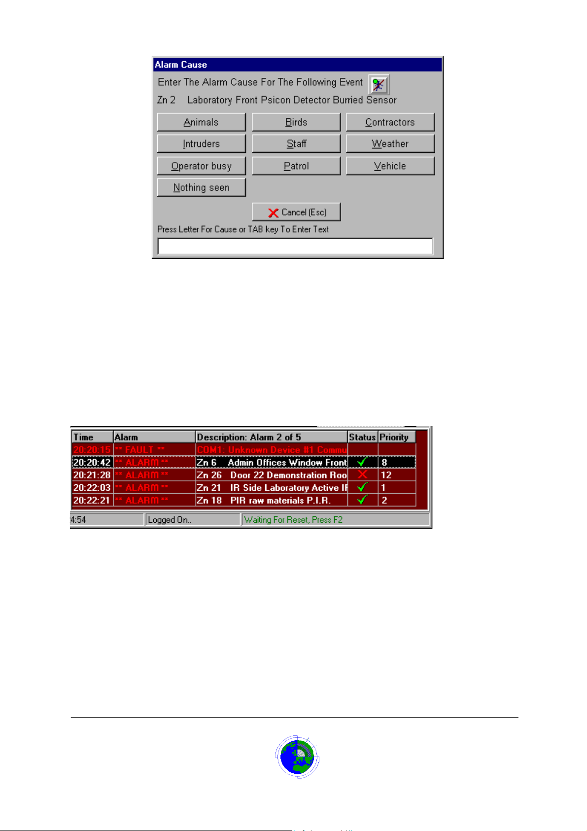
Once the cause has been entered the alarm condition will reset and any outputs set by the alarm will
now be de-energised. The system will return to normal operation showing the main site plan.
Up to 16 pre-defined causes can be set-up to customer requirements by the system provider at
installation. These pre- defined alarm causes are useful if using the alarm analysis report.
The Alarm Queue
The alarm queue contains any zones that have generated an alarm and have not been reset by the
operator up to its maximum of 20 alarms.
If there are any alarms in the queue, then the alarm queue is displayed at the bottom of the main screen
in place of the Last Events Window.
The alarm queue has five columns:
1. The ‘Time’ column contains the time the alarm occurred.
2. The ‘Alarm’ column contains the alarm cause:
ALARM = The alarm was caused by activation of the zones sensor
SHORT = The alarm was caused by a short-circuit of alarm device
TAMPER = The alarm was caused by an open-circuit or disconnection of the alarm device
FAULT = This type of alarm is not a zone on the system. It is a software-generated alarm for
system faults i.e. loss of communication with field panels, or equipment cabinet tamper
alarms.
3. The ‘Description Column contains the description text for the alarm. The column heading also tells
which alarm number is currently selected and how many are in the queue e.g. ‘Alarm 2 of 5’
4. The ‘Status’ column displays a clock symbol if an alarm has not been accepted. Once accepted
the Status column displays a red cross if the zones sensor is still not secure or a green tick if the zones
Datalog 3 User Manual - Page 16 of 66
CORTECH DEVELOPMENTS LTD
Page 17

sensor is now in a secure state. No status is given for ‘FAULT’ alarms.
5. The ‘Priority’ column will contain a number between 0 and 255. 255 is the highest priority, 1 is the
lowest and 0 means no priority. This allows the operator to select the most important alarm first.
Multiple Alarms
If more than one alarm should occur:
Accept the Alarms
Click the ‘Accept’ button or press the F1 function key to accept the alarms.
This will accept all the unaccepted alarms in the queue.
Select the Alarm to Reset
If the option ‘Follow Latest Alarm’ is selected in the User Setup options (standard)
The new alarm will automatically be selected if it has a priority equal to or higher than a
previously selected alarm.
If the option ‘Follow Latest Alarm’ is not selected in the User Setup options
The new alarm will automatically be select ed only if it has a priority higher than a pr e vious ly
selected alarm.
Alternatively use the Up/Down arrow keys and Press the <Enter> k ey or click on the relevant
alarm in the alarm queue to select an alarm to view
The map will display the maximum zoom view for the chosen alarm. The icon matching the
alarm will have changing border colours.
Reset the Alarm
If the alarm zone is secure, it can be reset:
Click the ‘Reset’ button or press the F2 function key.
If the option to enter an alarm cause has been en abled, a cause will have t o be entered for the
alarm before reset can take place.
The operator has two choices for entering a cause:
1. Select one of the pre-defined causes by clicking on the relevant button or typing the
underscored letter on the button.
2. Press the Tab key or click in the text box at the bottom of the dialog box and enter a
description of the cause, then select one of the pre-defined causes by clicking on the
relevant button or typing the underscored letter on the button.
Once the cause has been entered the alarm condition will reset and any outputs set by the alarm will
now be de-energised.
Repeat the select and reset procedure until all alarms have been reset
The system will return to normal operation showing the main site plan and Last Events window as soon
as all alarms have been reset.
If an alarm zone remains non-secure (red c ross in status column) it can not be reset. The optio ns are
either to wait until the zone becomes s ecure (status column has green t ick) or to inhibit the zone an d
then reset.
Datalog 3 User Manual - Page 17 of 66
CORTECH DEVELOPMENTS LTD
Page 18

Alarm Logging
The alarm history log will store:
1. The Date, Time and Description of the alarm occurrence
2. The Date, Time, Description and User name of when the alarm is accepted
3. The Date, Time and Description of when the alarm was reset plus the alarm cause if the
option is used
4. The Date, Time and comment text. If extra text was typed in the Alarm Cause dialog box.
This information can be viewed and printed using the ‘Review Database’ report
Datalog 3 User Manual - Page 18 of 66
CORTECH DEVELOPMENTS LTD
Page 19

Inhibiting Zones
Individual inputs can be inhibite d for m aintenance / repa ir , or where it is inco nv en ient to ha ve the alar ms
constantly activated i.e. in frequ ent l y used areas. When a zone is inhibited, should the zone ’s sens or
activate, the Datalog System will not generate an alarm or log the event in the database.
When a zone is inhibited, maps will display a yellow icon to denote the status.
On most systems, when the zone is inhibited and its sensor is activated, maps will display a red icon to
show the status. However some systems may have a software option to inhibit the zone in the alarm
panel in addition to the Datalog zone in which case the icon will remain yellow while in inhibit mode and
not change to red.
Certain zones will not allow inhib it ing, these are '24 Hour ' zone types.
Zones can be inhibited:
Individually by manual operation, using ‘Single Zone Inhibit’
In groups by manual operation, using ‘Group Inhibit’
In groups on a timer, using ‘Time Zones’
Individually on a timer, using the ‘Inhibit Timer’
Single Zone Inhibit
There are a number of ways to inhibit a single zone on the Datalog system:
1. If an icon for the zone is displayed on the main screen then click the right mouse button to enable
the short-cut menu, click Inhibit Zone.
or
2. If an icon for the zone is displayed on the map viewer then click the right mouse button to enable
the short-cut menu, click Inhibit Zone.
or
3. While on the main screen, press the Zone Inhibit button and enter your password. On the Zone
Inhibit Screen, scroll or page down to the relevant zone on the zone list, click to highlight the zone,
press <Enter>
or
4. While on the main screen, press the spacebar and enter your password. Scroll or page down to the
relevant zone on the zone list , click to highlight the zone, press <Enter>
or
5. If logged on, on the menu bar, select ‘Inhibit’, on the menu select ‘Single Zone Inhibit’, on the zone
list scroll or page down to the relevant zone, click to highlight the zone, press <Enter>
or
6. If logged on, on the menu bar, click the single zone inhibit button, on the zone list scroll or page
down to the relevant zone, click to highlight the zone, press <Enter>
Whichever option is used the zone will be inhibited, and where icons are displayed their colour will be
yellow when secure or red when not secure.
Single Zone Enable
There are a number of ways to enable a single zone on the Datalog system:
1. If an icon for the zone is displayed on the main screen then click the right mouse button to enable
the short-cut menu, click Enable Zone.
or
2. If an icon for the zone is displayed on the map viewer then click the right mouse button to enable
the short-cut menu, click Enable Zone.
Datalog 3 User Manual - Page 19 of 66
CORTECH DEVELOPMENTS LTD
Page 20
or
3. While on the main screen, press the Zone Inhibit button and enter your password. On the Zone
Inhibit Screen, scroll or page down to the relevant zone on the zone list, click to highlight the zone,
press <Enter>
or
4. While on the main screen, press the spacebar and enter your password. Scroll or page down to the
relevant zone on the zone list , click to highlight the zone, press <Enter>
or
5. If logged on, on the menu bar, select ‘Inhibit’, on the menu select ‘Single Zone Inhibit’, on the zone
list scroll or page down to the relevant zone, click to highlight the zone, press <Enter>
or
6. If logged on, on the menu bar, click the single zone inhibit button, on the zone list scroll or page
down to the relevant zone, click to highlight the zone, press <Enter>
Whichever option is used the zone will be enabled, and where icons are displayed their colour will be
grey when secure and the zone will alarm when not secure.
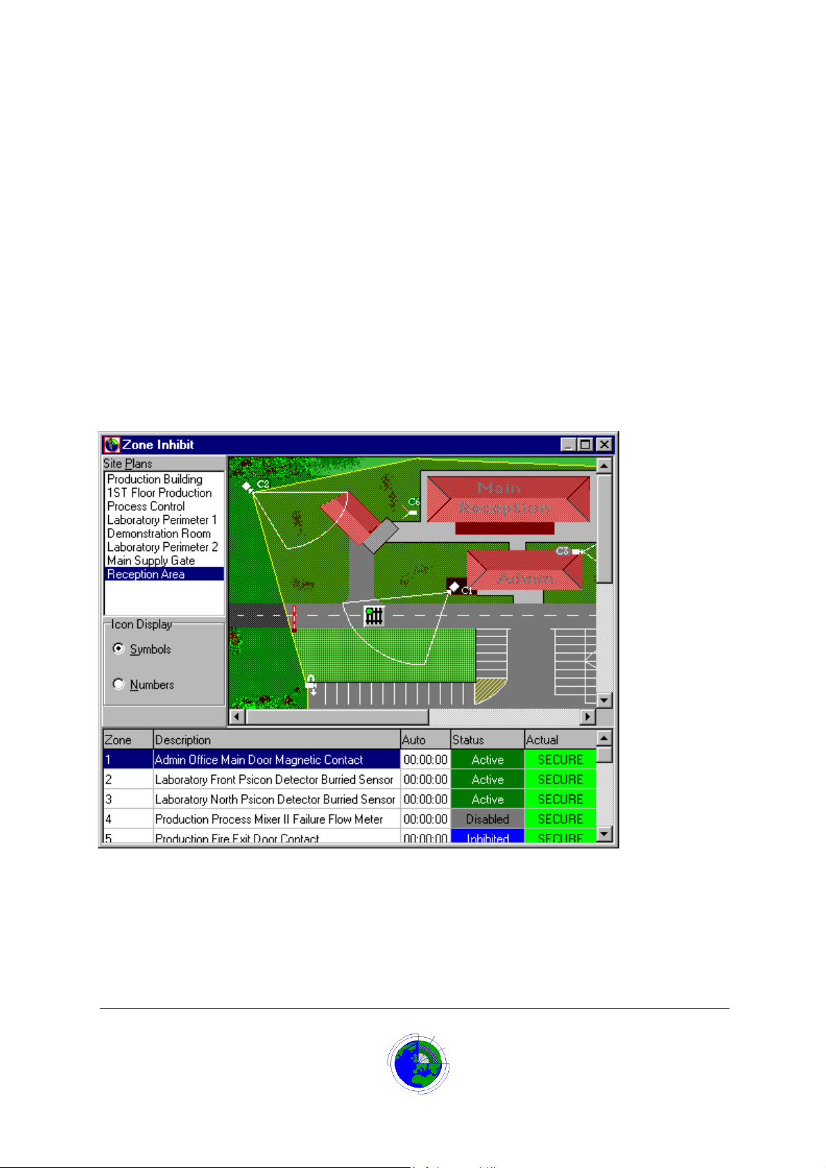
Zone Inhibit Screen
The zone inhibit screen displays when the ‘Zone Inhibit’ button is clicked, on the main screen or menu
panel, or ‘Single Zone Inhibit’ is selected from the ‘Inhibit’ menu.
Zone Inhibit List
The zone inhibit list at the bottom of the Zone Inhibit Screen, allows the operator to view the state of
zones.
Datalog 3 User Manual - Page 20 of 66
CORTECH DEVELOPMENTS LTD
Page 21
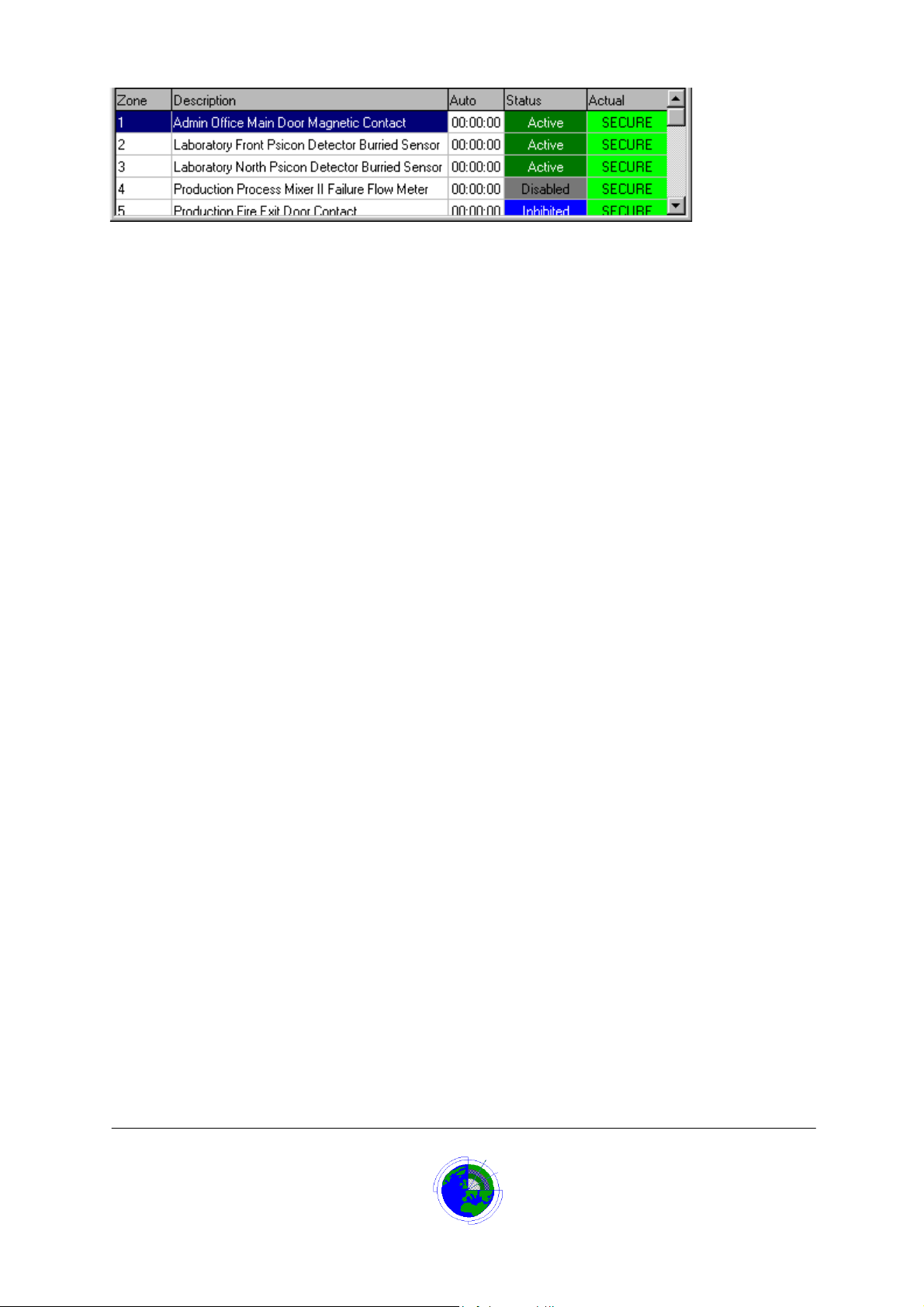
Column 1 is the zone number on the Datalog system.
Column 2 gives the description for the zone.
Column 3 would show the time to go before the auto-inhibit timer expires, when the inhibited zone would
enable.
Column 4 shows the zone status: Active, Inhibited, Disabled, or 24 Hour.
Column 5 shows whether the zone is currently secure or not secure
Group Inhibit
There are a number of ways to inhibit a group of zones on the Datalog system:
1. While on the main screen, press the Group Inhibit button and enter your password. On the Group
Inhibit list, scroll or page down to the relevant zone group, click to highlight the zone group, press
<Enter>
or
2. If logged on, on the menu bar, select ‘Inhibit’, on the menu select ‘Group Inhibit’, on the Group
Inhibit list scroll or page down to the relevant zone group, click to highlight the zone group, press
<Enter>
or
3. If logged on, on the menu bar, click the Group Inhibit button, on the Group Inhibit list scroll or page
down to the relevant zone group, click to highlight the zone group, press <Enter>
Whichever option is used the zones in the group will be inhibited, and where icons are displayed their
colour will be yellow when secure or red when not secure.
Group Enable
There are a number of ways to enable a group of zones on the Datalog system:
1. While on the main screen, press the Group Inhibit button and enter your password. On the Group
Inhibit list, scroll or page down to the relevant zone group, click to highlight the zone group, press
<Enter>
or
2. If logged on, on the menu bar, select ‘Inhibit’, on the menu select ‘Group Inhibit’, on the Group
Inhibit list scroll or page down to the relevant zone group, click to highlight the zone group, press
<Enter>
or
3. If logged on, on the menu bar, click the Group Inhibit button, on the Group Inhibit list scroll or page
down to the relevant zone group, click to highlight the zone group, press <Enter>
Whichever option is used the zones in the group will be enabled, and where icons are displayed their
colour will be grey when secure and will generate an alarm when not secure.
Group Inhibit List
The group inhibit list displays when the Group Inhibit button is clicked on the main screen or menu
panel, or the menu option is selected.
Datalog 3 User Manual - Page 21 of 66
CORTECH DEVELOPMENTS LTD
Page 22
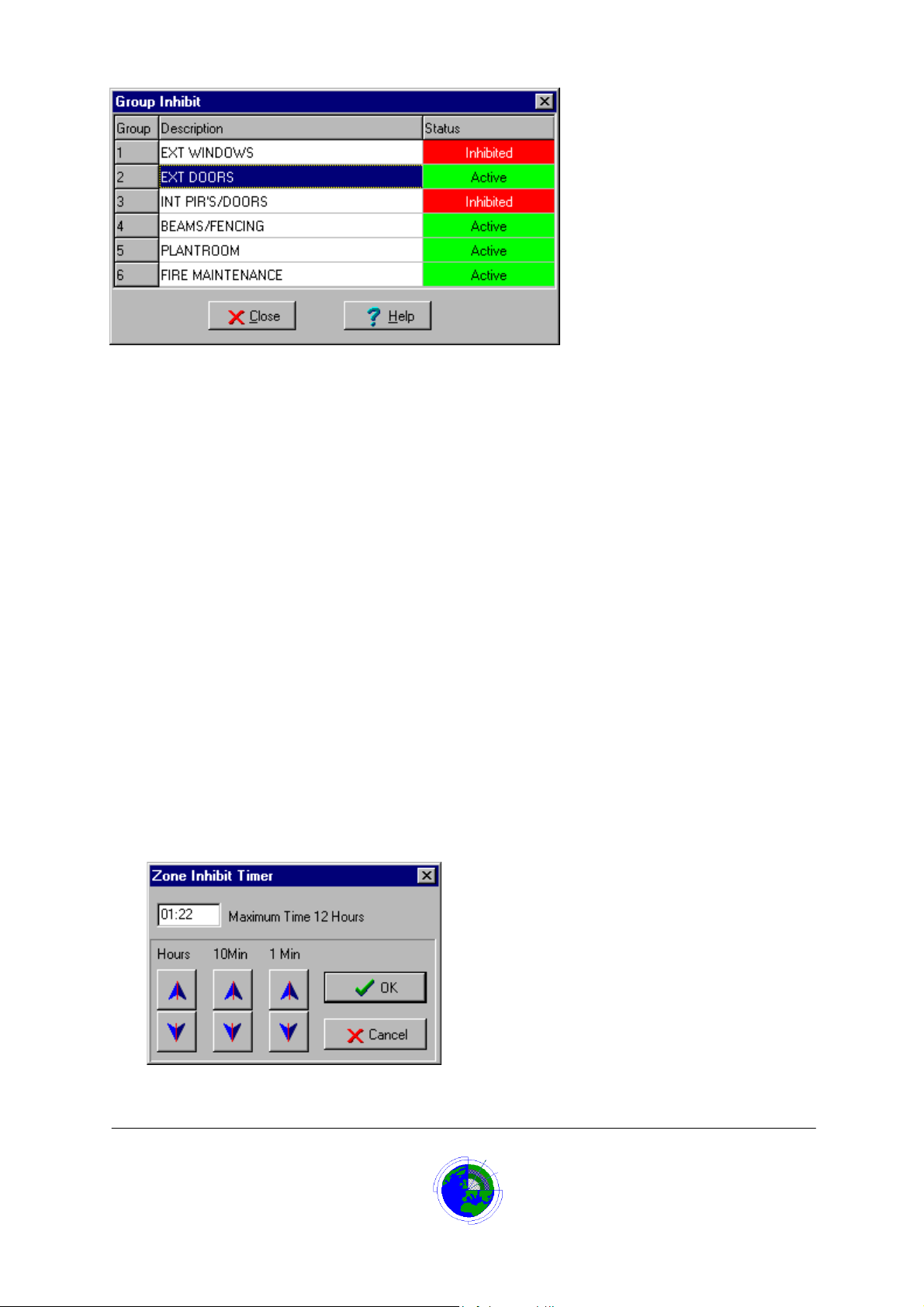
Column 1 is the zone group number on the Datalog system and can be in the range 1-100.
Column 2 gives the description for the group of zones.
Column 3 shows the zone group status: Active or Inhibited.
Zone Inhibit Timer
The Inhibit Timer sets the auto enable feature, allowing the user to inhibit a zone for a set time from 1
minute to a maximum of 12 hours. If the zone is already inhibited, then the timer can be used to extend
the inhibit time for the interval set, before it will automatically enable the zone.
To set the inhibit timer, display the timer by one of the following methods:
1. If an icon for the zone is displayed on the main screen then click the right mouse button to
enable the short-cut menu, click Inhibit Timer.
2. If an icon for the zone is displayed on the map viewer then click the right mouse button to
enable the short-cut menu, click Inhibit Timer.
3. While on the main screen, press the Zone Inhibit button and enter your password. On the
Zone Inhibit Screen, scroll or page down to the relevant zone on the zone list, click to
highlight the zone, press shift and <Enter>
4. While on the main screen, press the spacebar and enter your password. Scroll or page
down to the relevant zone on the zone list , click to highlight the zone, press shift and
<Enter>
5. If logged on, on the menu bar, select inhibit, on the menu select Single Zone Inhibit , on
the zone list scroll or page down to the relevant zone, click to highlight the zone, press
shift and <Enter>
6. If logged on, on the menu bar, click the single zone inhibit button, on the zone list scroll or
page down to the relevant zone, click to highlight the zone, press shift and <Enter>
Which ever method is used the inhibit timer will display
Datalog 3 User Manual - Page 22 of 66
CORTECH DEVELOPMENTS LTD
Page 23

Set the time using the arrow buttons then click OK.
The timer can be seen decrementing in the Auto column of the zone list.
The system will log the date, time, event = Auto-Inhibit, zone description and user setting the timer
The zone will automatically enable, when the timer elapses.
The system will log the date, time, event = Auto-Enable, zone description and user =System.
Notes on this Auto Enable feature: The above timed inhibit feature can be further enhanced by setting zones as
'auto- enable'. The system provider using the
Datalog 3
EDITOR can do this.
If the auto- enable f eature is ON f or a zone then the zone will auto enable if the i nhibit tim er is set and
counts down to zero OR if the inhib it timer is set and the zone input returns to a secure stat e. E.g. A
magnetic contact on a roller shutter door is set wit h auto enable ON, and the inhibit t imer is set to five
minutes.
The roller shutter zone will rem ain inhibit ed until eit her the ro ller shutter is closed an d the zone s ecured
OR the inhibit timer reaches zero after five m inutes. This pre vents the system being compr omised by a
zone remaining inh ibited for longer than was necessary. This auto enable feature shou ld only be used
on stable state sensors and not on movement detectors such as PIR devices.
Datalog 3 User Manual - Page 23 of 66
CORTECH DEVELOPMENTS LTD
Page 24
Output Control
Many field panels have the ability to switch output relays. The Datalog 3 system also has the ability to
switch these output relays.
The output relays are assigned to named groups. A group can have 1 to 8 output relays assigned to it.
The Datalog 3 system can have up to 100 output groups. An output relay can belong to more than one
group.
These groups are set-up by the system provider at installation.
The output group is activated by:
1. A zone going in to an alarm state
2. Manually by the operator selecting the group from a list
3. By Timezone
Alarm Operated Output
When the system is set-up at installation an output group can be assigned to a zone. The output group
can contain between 1 and 8 output relays.
When the zone goes into alarm it will automatically energise (set) the output relays. This is useful for
scenarios such as switching on flood lamps when an external infra-red sensor is tripped.
The outputs then remain set until the operator resets the alarm whereupon the outputs will de-energise
(reset).
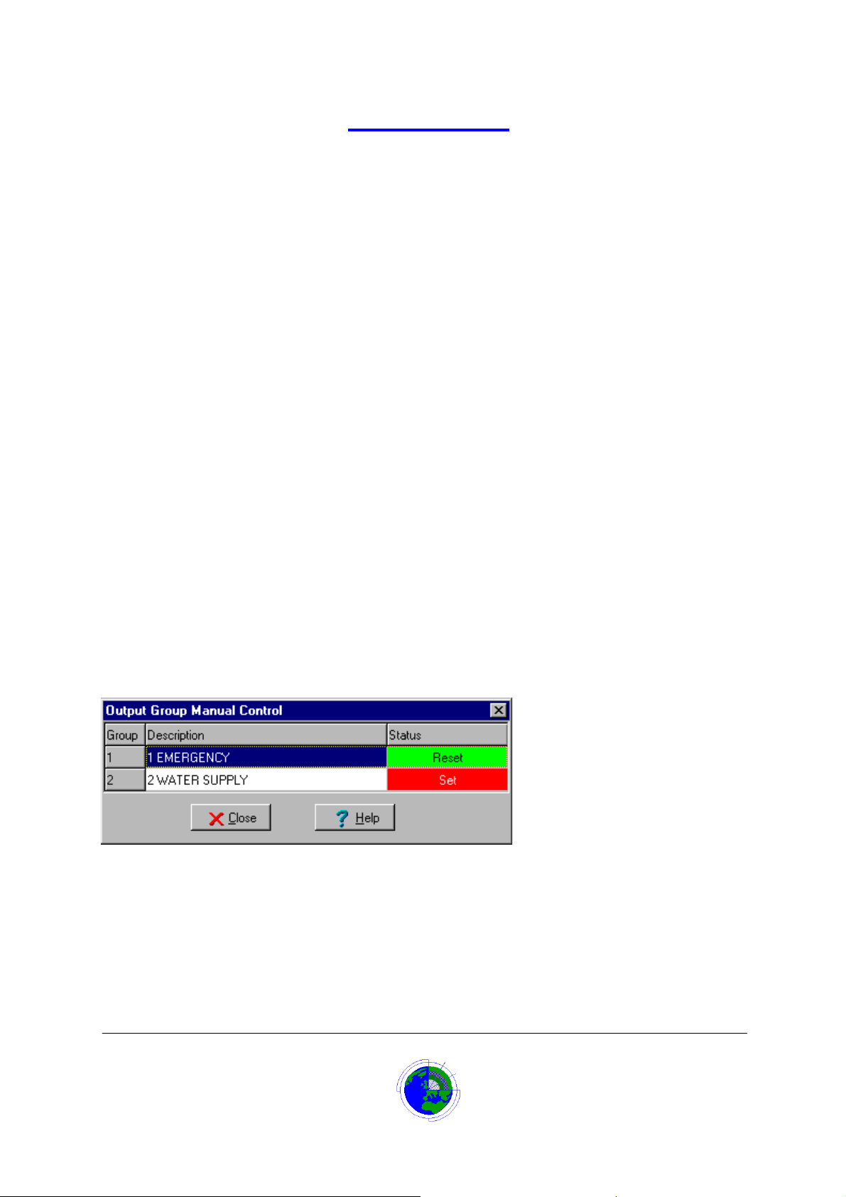
Manual Output Control
The operator can switch a group of output relays by:
From the Main screen click ‘Log on’
The menu panel displays.
1. Select ‘System’ ! ‘Output Control’
Or
2. Click Output Control button
The ‘Output Control Manual Control’ dialog box displays.
3. Scroll and click on the relevant output group
The Description is highlighted.
4. To activate or set the output relays press <Enter> key or double click the description
The output relays status changes to set and a red colour.
5. To de-activate or reset the output relays press <Enter> key or double click the description
The output relays status changes to Reset and a green colour.
Datalog 3 User Manual - Page 24 of 66
CORTECH DEVELOPMENTS LTD
Page 25

Time Zone Operated Output Control
An output group can be switched by a time zone.
A time zone is an event timer that can be used to cause output groups to switch automatically on
selected days.
The timer allows one ‘on’ time period during selected days from Monday to Sunday. To set this up it is
necessary to add a new timezone.
1. From the Main screen click ‘Log on’
The menu panel displays.
2. Select ‘System’ ! ’User Setup’.
The ‘User Setup’ dialog box displays.
3. Click the ‘Setup Automatic TimeZones’ button.
The ‘Time Zone Form’ displays
4. Click the ‘New’ button
5. In the ‘Description’ box type a name for the new time zone
6. Click to check any of the day boxes, Monday to Sunday that the output group is to be
activated.
7. Set the time when the output group is to be activated on the selected days, in the ‘Time
On’ box
8. Set the time when the output group is to be reset on the selected days, in the ‘Time Off’
box
9. Select ‘Output Group’ from the ‘Action’ list box
10. Select the group of output relays to switch on when the time zone is on, from the ‘Group’
list box.
11. Click the ‘OK’ button to store the new time zone
The new time zone details will display in the time zone list.
.
Datalog 3 User Manual - Page 25 of 66
CORTECH DEVELOPMENTS LTD
Page 26
Time Zones
A time zone is an event timer that can be used to cause certain functions to occur automatically on
selected days.
The timer allows one ‘on’ time period during selected days from Monday to Sunday.
The standard uses for this timer are:
1. To inhibit groups of zones for a period during the day. i.e. Passive Infra-red sensors during
working hours.
2. To switch relays on for a period during the day. i.e. to unlock a gate during working hours.
Additionally Cortech Developments could write a custom function to assign to the time zone to meet
specific requirements.
When a new time zone is added, the operator can be given a description that reflects its use.
Datalog 3 can store up to 64 time zones.
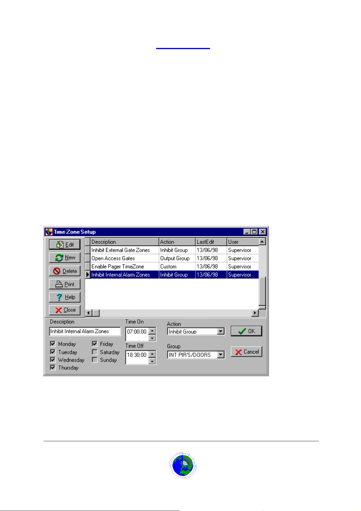
Time Zone Form
The time zone form allows the operator a number of options.
1. Display a time zone.
2. Add a time zone.
3. Edit a time zone.
4. Delete a time zone.
5. Run a time zone report to screen or printer.
Time Zone Description
Enter a description for the time zone (up to 30 characters).
Give the time zone a name that describes the action it is going to control
For example:
“Inhibit internal alarms”
“Switch off perimeter lights”
Datalog 3 User Manual - Page 26 of 66
CORTECH DEVELOPMENTS LTD
Page 27

Time Zone Time On
Set up the start time for the time zones ‘on’ period for any selected day.
For example:
If it is required to inhibit alarms inside a building from 07:00 until 19:00 Monday to Friday,
the time zone’s on period starts at 07:00 and ends at 19:00.
The Time On will be 07:00:00
Time Zone Time Off
Set up the end time for the time zones ‘on’ period for any selected day.
For example:
If it is required to inhibit alarms inside a building from 07:00 until 19:00 Monday to Friday,
the time zone’s on period starts at 07:00 and ends at 19:00.
The Time Off will be 19:00:00
Time Zone Monday-Sunday
Click in each day check box for the days that the time zone has an ‘on’ period.
For example:
If it is required to inhibit alarms inside a building from 07:00 until 19:00 Monday to Friday,
the time zone’s on period starts at 07:00 and ends at 19:00.
Days Monday to Friday should have their check boxes ticked, but Saturday and Sunday
have no ‘on’ period and so should not be ticked.
Time Zone Action List
Select the required action that the time zone is to initiate. The options are:
1. No Action
The time zone will not do anything when the time period is on. This option would only be
selected if the time zone is being set up for future use or its action is being suspended.
2. Inhibit Group
When the time zone is on it will inhibit the group of zones named in the group list box
below. This prevents the Datalog annunciating any of the zones in the group, if the zone
goes into an alarm state.
3. Output Group
When the time zone is on it will switch on the group of output relays named in the group list
box below.
4. Custom
Custom is an option, which will only be available when special software has been installed.
The time zone will probably be set up at installation for a specific purpose.
For example:
To inhibit alarms inside a building from 07:00 until 19:00 Monday to Friday, the time zone’s
on period starts at 07:00 and ends at 19:00. The Action list box will be set to ‘Inhibit Group’.
Time Zone Group List
If the Action selected was ‘Inhibit Group’, this list contains zone groups. Select the group of zones to
inhibit when the ti me zone is on.
If the Action selected was ‘Output Group’, this list contains output groups. Select the group of output
relays to switch on when the time zone is on.
These groups are set up on the system at install time and, through consultation, should have names that
assist selection.
If names need to be changed or more groups are required, contact the equipment supplier.
Datalog 3 User Manual - Page 27 of 66
CORTECH DEVELOPMENTS LTD
Page 28

Adding a New Time Zone
To add a new time zone:
1. From the Main screen click ‘Log on’
The menu panel displays.
2. Select ‘System’ ! ’User Setup’.
The ‘User Setup’ dialog box displays.
3. Click the ‘Setup Automatic TimeZones’ button.
The ‘Time Zone Form’ displays.
4. Click the ‘New’ button
5. In the ‘Description’ box type a name for the new time zone
6. Click to check any of the day boxes, Monday to Sunday that the time zone is to operate on.
7. Set the start time for the time zone on the selected days, in the ‘Time On’ box
8. Set the end time for the time zone on the selected days, in the ‘Time Off’ box
9. Select what is to happen during the on time of the time zone from the ‘Action’ list box
If the action selected was ‘Inhibit Group’, select the group of zones to inhibit when the time zone
is on, from the ‘Group’ list box.
If the action selected was ‘Output Group’, select the group of output relays to switch on when
the time zone is on, from the ‘Group’ list box.
10. Click the ‘OK’ button to store the new time zone
The new time zone details will display in the time zone list.
Editing a Time Zone
To edit an existing time zone:
1. From the Main screen click ‘Log on’
The menu panel displays.
2. Select ‘System’ ! ’User Setup’.
The ‘User Setup’ dialog box displays.
3. Click the ‘Setup Automatic TimeZones’ button.
The ‘Ti me Zone Form’ displays.
4. Click on the relevant time zone in the time zone list.
The time zone is highlighted.
5. Click the ‘Edit’ button
6. Click in the ‘Description’ box and modify the time zone name if necessary
7. Click to check/uncheck any of the day boxes, Monday to Sunday that the time zone is to
operate on.
8. Set the start time for the time zone on the selected days, in the ‘Time On’ box
9. Set the end time for the time zone on the selected days, in the ‘Time Off’ box
10. Select what is to happen during the on time of the time zone from the ‘Action’ list box
If the action selected was ‘Inhibit Group’, select the group of zones to inhibit when the time zone
is on, from the ‘Group’ list box.
If the action selected was ‘Output Group’, select the group of output relays to switch on when
the time zone is on, from the ‘Group’ list box.
11. Click the ‘OK’ button to store the changes.
The modified time zone details will display in the time zone list.
Datalog 3 User Manual - Page 28 of 66
CORTECH DEVELOPMENTS LTD
Page 29

Displaying a Time Zone
To display an existing time zone:
1. From the Main screen click ‘Log on’
The menu panel displays.
2. Select ‘System’ ! ’User Setup’.
The ‘User Setup’ dialog box displays.
3. Click the ‘Setup Automatic TimeZones’ button.
The ‘Time Zone Form’ displays.
4. Click on the relevant time zone in the time zone list.
The time zone details are displa yed, gre yed out, in the field boxes .
Deleting a Time Zone
To delete an existing time zone:
1. From the Main screen click ‘Log on’
The menu panel displays.
2. Select ‘System’ ! ’User Setup’.
The ‘User Setup’ dialog box displays.
3. Click the ‘Setup Automatic TimeZones’ button.
The ‘Time Zone Form’ displays.
4. Click on the relevant time zone in the time zone list.
The time zone is highlighted.
5. Click the ‘Delete’ button
A confirmation dialog box displays.
6. Click the ‘OK’ button to confirm the deletion or cancel to abort the deletion.
The time zone details will be removed from the time zone list.
Datalog 3 User Manual - Page 29 of 66
CORTECH DEVELOPMENTS LTD
Page 30
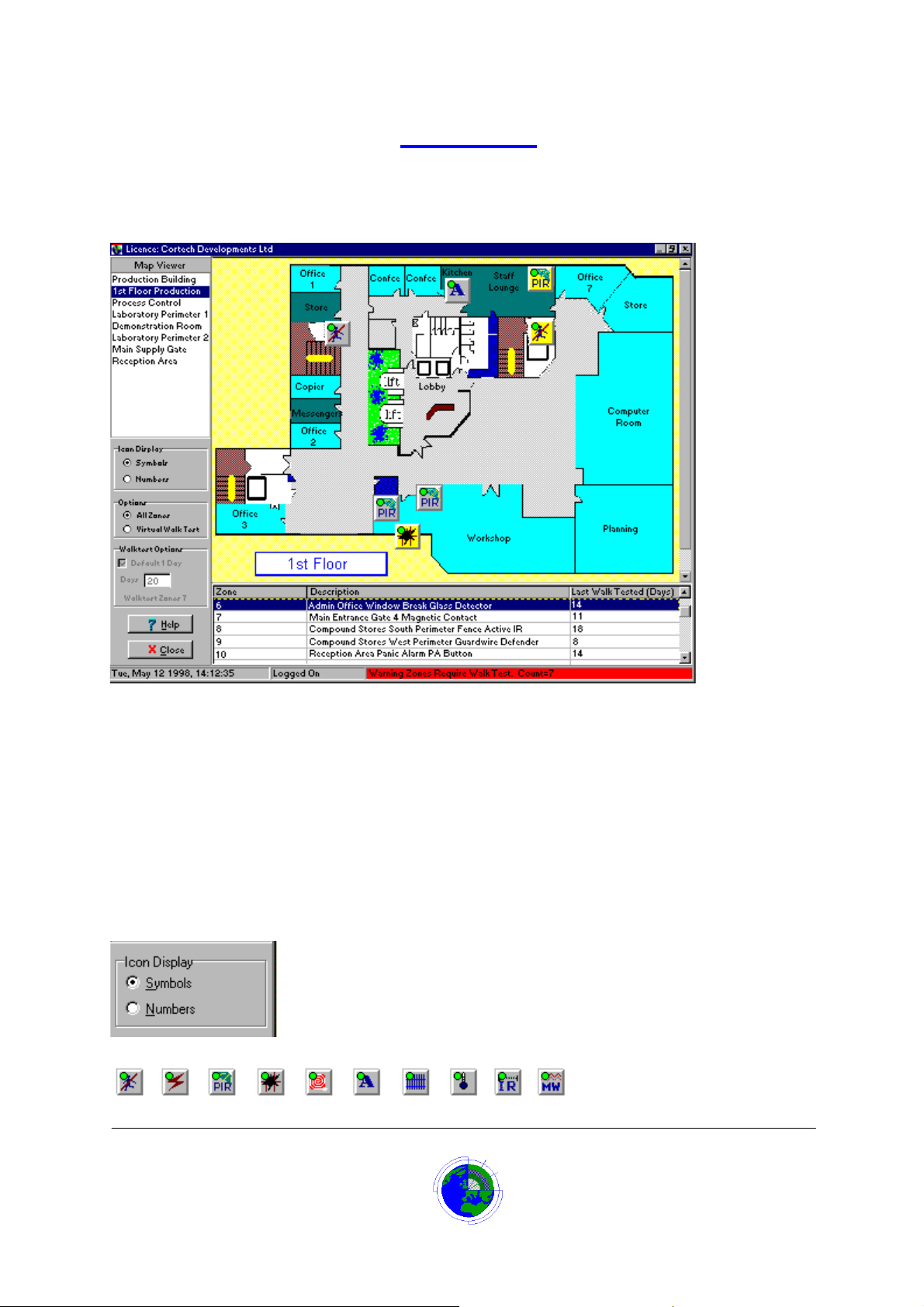
Map Viewer
Clicking the Map Viewer Button, or pressing the F9 key, launches the Map Viewer screen.
The following graphic is the default Map Viewer layout when Icon Display is set to ‘Symbols’ and
Options is set to ‘All Zones’.
Click on the relevant area of the Map Viewer graphic below for more help.
Map Selection Box
The map selection box allows the operator to click on a map title and view the associated map.
When the map is displayed it will show the zone positions either as symbols representing the type of
alarm, or numbered and coloured Icons, depending on the setting of the Icon Display radio button.
Icon Display
When a map is selected and displayed in Map Viewer or Zone Inhibit, the map will show the zone
positions by an icon represent ati on.
If the Icon Display radio button is set to ‘Symbol’
The zone will be shown as a button like icon with a graphic that represents the type of alarm.
Datalog 3 User Manual - Page 30 of 66
CORTECH DEVELOPMENTS LTD
Page 31

If the Icon Display radio button is set to ‘Numbers’
The zone will be shown as a larger numbered, coloured button like icon displaying the zone number and
state.
Map Viewer Options
When the ‘Options’ radio button is set in the default state of ‘All Zones’, the list at the bottom of the Map
Viewer screen shows all the zones on the Datalog 3 system.
Walk Test Status can be viewed on the Map Viewer Screen by setting the ‘Options’ radio button to
‘Virtual Walk Test’. The list at the bottom of the screen will switch from showing the zone list to showing
zones requiring a Walk Test. The default Walk Test list shows any zones that are more than I day past
the Walk Test alarm period.
Map Viewer Walk Test Options
Walk Test Status can be viewed on the Map Viewer Screen by setting the ‘Options’ radio button to
‘Virtual Walk Test’. The list at the bottom of the screen will switch from showing the zone list to showing
zones requiring a Walk Test.
The default Walk Test list shows any zones that are more than I day past the Walk Test alarm period.
This list can be filtered by increasing the days past the Walk Test alarm period.
To do this, remove the tick from the ‘Default 1 Day’ check box in the Walk Test Options box, and
entering the number of days in the ‘Days’ field.
The text ‘Walk Test Zones X’ below the Days field shows how many zones have been found where X is
the count of zones.
If an icon
omitted from the Walk Test.
is displayed next to the number of days since walk test, this indicates that this zone is
Datalog 3 User Manual - Page 31 of 66
CORTECH DEVELOPMENTS LTD
Page 32

Walk Test
The Datalog 3 system can manage the site’s zone testing by assisting with walk test procedures.
The User Setup screen allows the user to define the period of days the system will allow a zone to
operate without an alarm being received from that zone. Once that period expires, the system will
generate an alarm to annunciate that a walk test is required.
In addition the user can also set the number of days before the walk test alarm occurs that the system
should issue a warning mess age.
Walk Test Status can be viewed on the Map Viewer Screen by setting the ‘Options’ radio button to
‘Virtual Walk Test’. The list at the bottom of the screen will switch from showing the zone list to showing
zones requiring a Walk Test. The default Walk Test list shows any zones that are more than I day past
the Walk Test alarm period. This list can be filtered further by increasing the days past the Walk Test
alarm period. To do this, remove the tick from the ‘Default 1 Day’ check box in the Walk Test Options
box, and entering the number of days in the ‘Days’ field
Zones that have exceeded the walk test period will be logged and printed when an end of day analysis
report is run.
The information can also be reviewed in a Walk Test report, which is based on these settings.
It may not be possible for site staff to walk test some zones, they may be inaccessible without special
knowledge or equipment, such as equipment failure and tamper alarms. An engineer’s option is
available to omit alarms from the walk test.
If a zone is omitted from the Walk Test an icon
in the Map Viewer list.
Walk test levels can also be individually tailored to meet a client’s specific requirement. If a particular
zone is given its own unique threshold value for either the 'Warning' or 'Alarm' level, then user settable
thresholds will not apply to this zone. Therefore it is possible to give every zone on the system its own
set of walk test thresholds independent of the user settable value. This configuration has to be carried
out by Cortech Developments.
is displayed next to the number of days since walk test
Omit Zones from Walk Test
To Omit a zone from Walk Test:
1. On the Menu Panel select System !Engineer Setup
2. Click the bottom Add button.
A list of all zones will display in numeric order.
If preferred the zones may be viewed in alphabetic order by pressing the sort button.
3. Select and highlight the relevant zone.
4. Click the OK button.
The zone number and description will be entered in the ‘Zones Omitted from Walk Test’ list.
5. Click OK button on Engineer Setup window.
Re-instate Walk Test Zone
To re-instate an omitted Walk Test zone:
1. On the Menu Panel select System !Engineer Setup
A list of all omitted zones will display in numeric order in the lower window.
2. Select and highlight the relevant zone to re-instate.
3. Click the lower Delete button.
The zone number and description will be deleted from the omitted Walk Test list.
4. Click OK button on Engineer Setup window.
Datalog 3 User Manual - Page 32 of 66
CORTECH DEVELOPMENTS LTD
Page 33

System Users and Passw ords
In order to use the Datalog 3 system an operator has to be assigned as a system user and given a
password.
Most of the functions of the Datalog 3 system require a password to be entered before they can be
used.
The password serves two purposes:
1. System security Restricting access to many of the Datalog functions.
2. System audit Enables the password user’s name to be entered in to the history log to
inform the system manager as to who was responsible for changes made and alarm reset.
Passwords are set-up in the ‘Edit Password’ option of the password menu, normally by the system
manager. The option to edit passwords is usually removed from most other staff by not ticking the ‘Edit
All Passwords’ check box. However all system users are allowed to change there own passwords.
A Password
A password can be 1 to 20 characters long, the system does not check the case, therefore if you use
upper-case (capital) letters the system will accept the password entered in lower-case.
To keep your password secure don’t use passwords that people can guess.
It is common for people to use car makes, partners names, words in connection with sports and
hobbies, so try to avoid using these.
If you are a slow, one finger, typist, people looking over your shoulder can see the password your
entering. Try to add some characters that require the shift key, it is difficult for someone to watch right
and left hand at the same time. This also can make a password more difficult to guess e.g. golf could be
entered as (golf).
Above all you need to use a password you can remember.
Master Password Setup Screen
The master password setup screen allows the operator a number of options.
1. Add a new user to the system.
2. Edit an existing user and password.
3. Delete an existing user.
4. Display a users details.
5. Run a password report to screen or printer.
Datalog 3 User Manual - Page 33 of 66
CORTECH DEVELOPMENTS LTD
Page 34
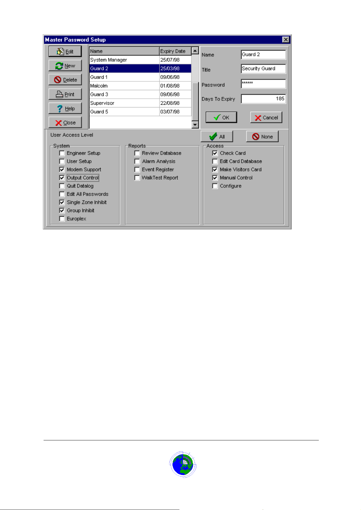
Master Password User List
The user list on the Master Password screen shows the users name and the date the password will
expire. A user name has to be clicked on to select and highlight, before editing or deleting a password or
user details.
Master Password Name Field
The Name field on the Master Password Setup screen should contain the user’s name. This name is
used to reference the password and is stored against events in the history log. When a user logs on, the
name appears in the menu panel’s user information box.
The maximum number of characters for the name is 30.
Master Password Title Field
The Title field on the Master Password Setup screen should contain the user’s title e.g. Security Guard.
When a user logs on, the title appears in the menu panel’s user information box.
The maximum number of characters for the title is 30.
Master Password Field
The Password field on the Master Password Setup screen should contain the user’s password. The
password is never displayed, asterisks are displayed in place of the characters. The user logs on with
the password, the system then cross-references the password to a user name and the user name is
then used for log purposes.
The password can be 1 to 20 characters and is not case-sensitive.
Datalog 3 User Manual - Page 34 of 66
CORTECH DEVELOPMENTS LTD
Page 35

Master Password Days to Expiry Field
The Days to Expiry field on the Master Password Setup screen allows the system manager to enter a
time period, in days, before the user’s password automatically expires.
In addition a warning message of expiry of the password can be set up to display before expiry every
time a user logs on. This option is defined in the User setup screen where it is possible to set the
number of days before expiry that the warning will display.
Master Password User Access Level
The User Access Level area of the screen contains three separate areas of check boxes.
1. System. The system manager should click to tick any check boxes that the user is allowed
to access from the menus.
2. Reports Allows the system manager to assign various report options to a user by ticking
the relevant check boxes.
3. Access. This option is only used if your system has the software option to operate an
access control system. If it has then the check boxes can be ticked to allow these options.
A button is provided with two green tick symbols and a caption ‘All’. Clicking this button will tick all the
check boxes, assigning all functions to a user.
Another button with a no entry symbol and a caption ‘None’. Clicking this button will clear all the ticks
from the check boxes removing all functions from the user.
Adding a New User and Password
To add a new system user:
1. From the Main screen click ‘Log on’
The menu panel displays.
2. Select ‘Password’ ! ’Edit Password’.
The ‘Master Password Setup ’ dialog box displ a ys.
3. Click the ‘New’ button
4. In the ‘Name’ field, type the user’s name (Up to 30 characters)
5. In the ‘Title’ field, enter the users job title (Up to 30 characters)
6. In the ‘Password’ field, enter the password the new user will have to enter in order to log
on(1-20 characters)
The password is never shown on any screens, asterisks are displayed.
7. Enter the number of days before the password automatically expires in the ‘Days to
Expiry’ field (1-32767)
8. Under the user access level caption, tick the check boxes for the functions that this user is
allowed to use. Click on a ticked check box if it is wished to remove a tick. The ‘All’ button
ticks all check boxes. The ‘None’ button removes all ticks from check boxes.
Click the ‘OK’ button to store the new user and password.
The new User details will display in the User list.
Editing an Existing User and Password
To edit an existing system user:
1. From the Main screen click ‘Log on’
The menu panel displays.
2. Select ‘Password’ ! ’Edit Password’.
The ‘Master Password Setup ’ dialog box displ a ys.
3. Click on the relevant user name in the user list to select and highlight.
4. Click the ‘Edit’ button
Datalog 3 User Manual - Page 35 of 66
CORTECH DEVELOPMENTS LTD
Page 36

5. If the user name is to be changed, in the ‘Name’ field, highlight and overtype the user’s
name
6. If the user’s title is to be changed, in the ‘Title’ field, highlight and overtype the users job
title
7. If the password is to be changed, in the ‘Password’ field, highlight and overtype the
password.
The password is never shown on any screens, asterisks are displayed.
8. If it is wished to change the period of days before the password expires, highlight and
overtype the number of days to expiry in that field.
9. Under the user access level caption, tick the check boxes for the functions that this user is
allowed to use. Click on a ticked check box if it is wished to remove a tick. The ‘All’ button
ticks all check boxes. The ‘None’ button removes all ticks from check boxes.
10. Click the ‘OK’ button to store the new user and password
The modified User details will display in the User list.
Displaying Users and Password
To display an existing system user’s details:
1. From the Main screen click ‘Log on’
The menu panel displays.
2. Select ‘Password’ ! ’Edit Password’
The ‘Master Password Setup ’ dialog box displ a ys.
3. Click on the relevant user name in the user list to select and highlight.
The users details will be displayed, greyed out, in the field boxes.
.
Deleting a User and Password
To delete an existing system user from the system:
1. From the Main screen click ‘Log on’
The menu panel displays.
2. Select ‘Password’ ! ’Edit Password’.
The ‘Master Password Setup ’ dialog box displ a ys.
3. Click on the relevant user name in the user list to select and highlight.
4. Click the ‘Delete’ button
A confirmation dialog box displays.
5. Click the ‘OK’ button to confirm the deletion
The User details will be removed from the User list and the password will no longer be accepted.
Changing Your Password
To change your own password:
1. From the Main screen click ‘Log on’
The menu panel displays.
2. Select ‘Password’ ! ’Change Password’.
Or
3. Click the ‘Change Password’ button (button with the padlock icon)
The ‘Enter Password’ dialog box displays.
Datalog 3 User Manual - Page 36 of 66
CORTECH DEVELOPMENTS LTD
Page 37
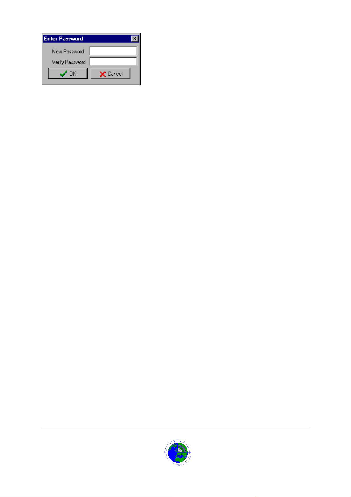
1. Type in your new password in the ‘New Password field’(1-20 characters)
The password is never shown on any screens, asterisks are displayed, so you must enter it again in the
‘Verify Password’ field to confirm.
2. Type your new password again in the ‘Verify Password field’
3. Click the ‘OK’ button to store the change.
If the two password fields do not match or the password is the same as your previous password, a
message will be displayed to inform you of that and you will then be prompted to enter them again.
Datalog 3 User Manual - Page 37 of 66
CORTECH DEVELOPMENTS LTD
Page 38
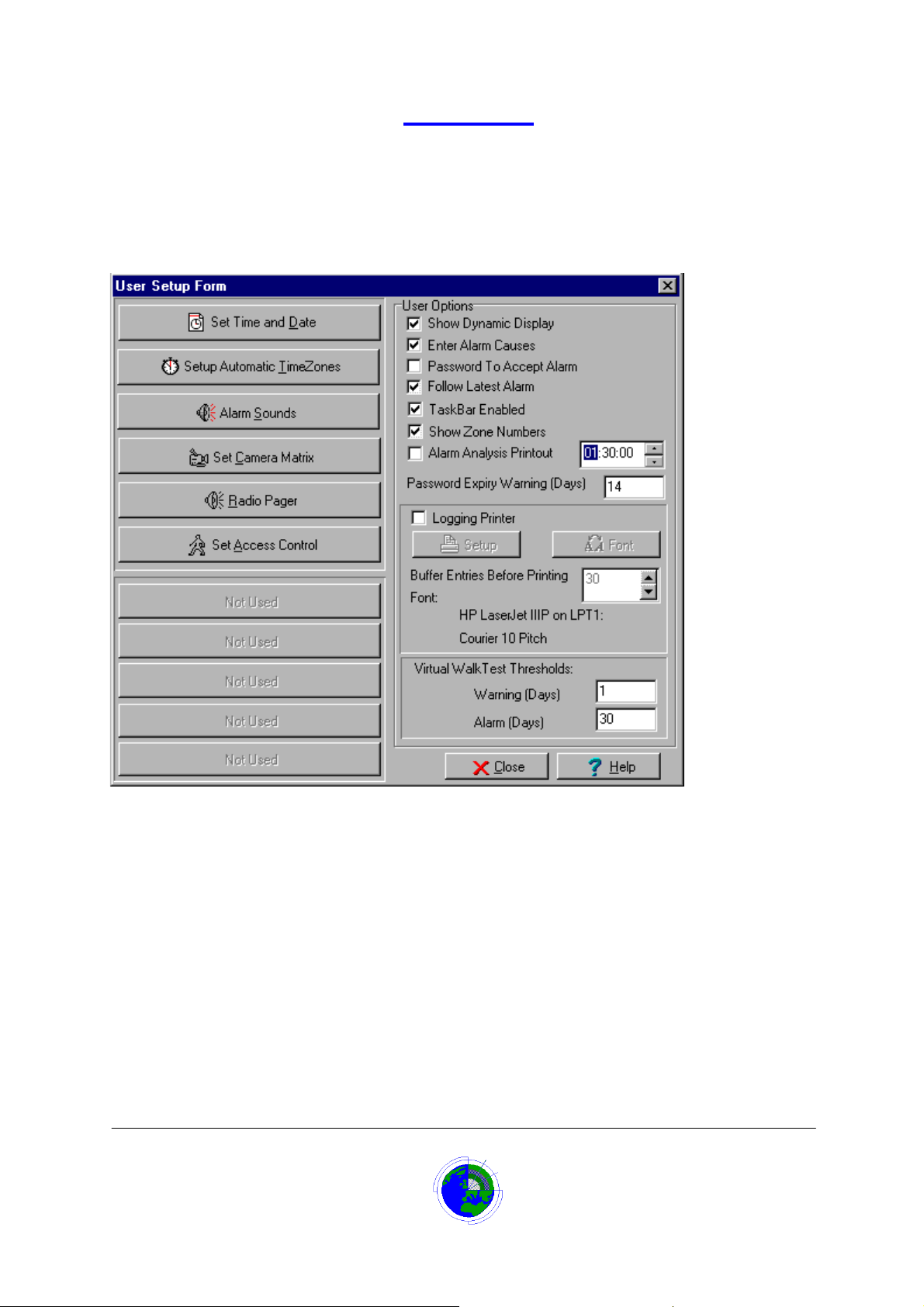
User Setup
The User Setup screen allows the user to program a number of system options. In most instances these
options are for initial set up and once set the User Setup menu option will be rarely used. The system
manager will probably set the options and then password restrict access by other operators.
Buttons available will depend on the external equipment controlled by the Datalog system, i.e. the set
‘Camera Matrix button’ will be disabled if the system does not control a camera system. The not used
buttons could become available if needed for other equipment.
Click on the relevant area of the user set up form below for more help.
Time Setting
To change the time:
1. Log on
The menu panel displays.
2. Select ‘System’ ! ’User Setup’.
The ‘User Setup’ dialog box displays.
3. Click the ‘Set Time and Date’ button.
The ‘Set Time and Date’ dialog box displays.
Datalog 3 User Manual - Page 38 of 66
CORTECH DEVELOPMENTS LTD
Page 39
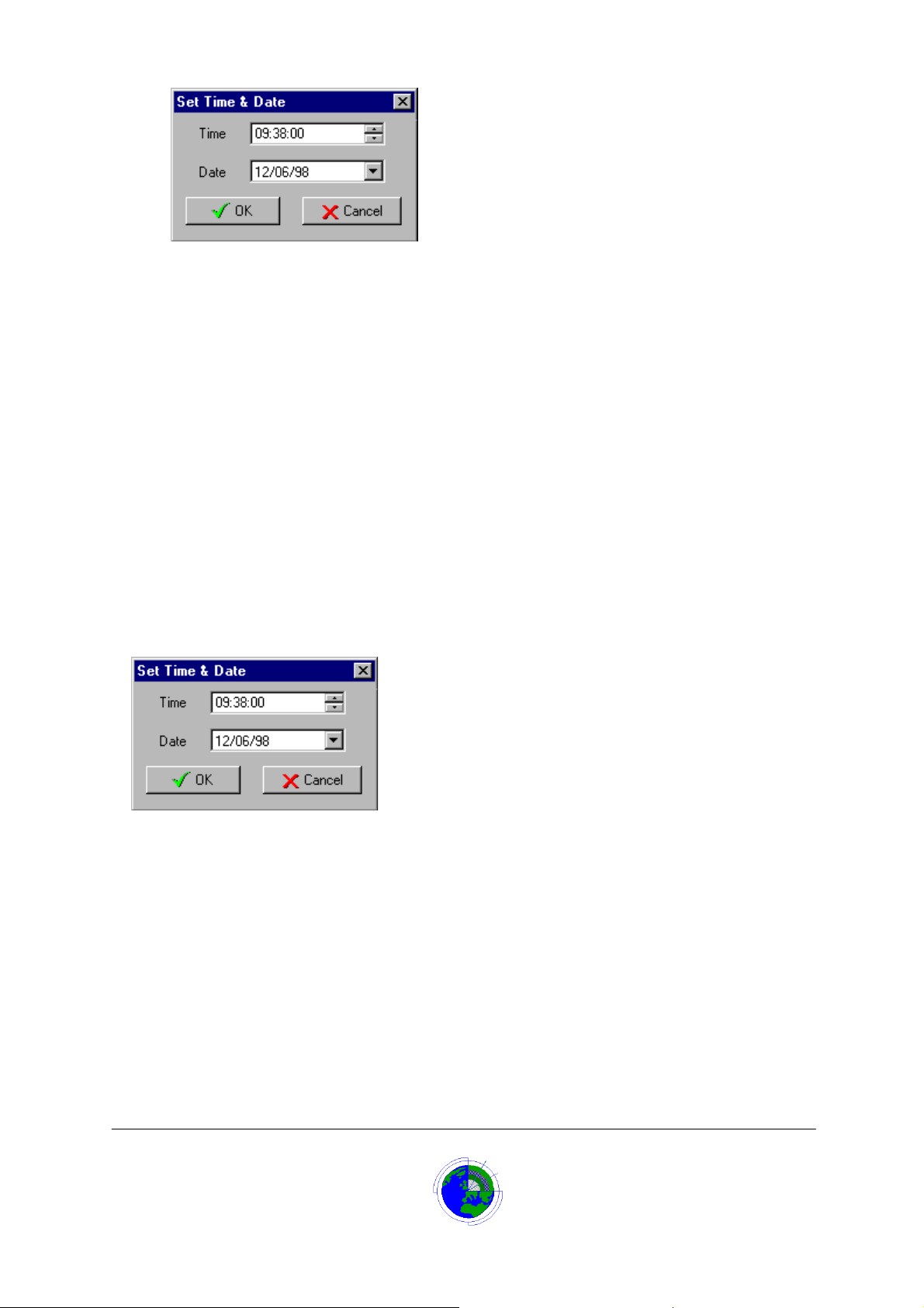
The time is in the format hh:mm:ss
1. Click on the ‘hh’ digits.
The hours digits are highlighted
Either:
2. Use the arrow keys on the right to increment/decrement the hours
Or
Overtype with the new hours
Repeat steps 4 and 5 for minutes and seconds digits
3. Click ‘OK’ button to store new date.
Date Setting
To change the date:
1. Log on
The menu panel displays.
2. Select ‘System’ ! ’User Setup’.
The ‘User Setup’ dialog box displays.
3. Click the ‘Set Time and Date’ button.
The ‘Set Time & Date’ dialog box displays.
The date is in the format dd/mm/yy
1. Either:
Click on the ‘dd’ digits
The day digits are highlighted
Overtype with the new day digits
Repeat above for ‘mm’ and ‘yy’ digits
Or
Click arrow button to right of date and select the date from the calendar
2. Click ‘OK’ button to store the new date
Datalog 3 User Manual - Page 39 of 66
CORTECH DEVELOPMENTS LTD
Page 40

Setup Automatic Time Zones Button
Clicking the ‘Setup Automatic Time Zones’ button, on the ‘User Setup’ dialog box, accesses the time
zone form.
The time zone form allows the operator a number of options.
1. Display a time zone.
2. Add a time zone.
3. Edit a time zone.
4. Delete a time zone.
5. Run a time zone report to screen or printer.
Show Dynamic Display
If this option is checked in the ‘System’ ! ’User Setup’ dialog box, Icons will display the position of
zones by their position on a map, and the status of the zones by their colour.
Enter Alarm Cause
If an option is checked in the ‘System’ ! ’User Setup’ dialog box, ‘Enter Alarm Cause’, then when the
operator resets an alarm, an Alarm Cause dialog box will request an operator comment on the cause of
the alarm.
The operator has two choices for entering a cause:
1. Use one of the pre-defined causes by clicking on the relevant button or typing the
underscored letter on the button.
2. Press the Tab key or click in the text box at the bottom of the dialog box and enter a
description of the cause. Then click on the relevant cause button
Once the cause has been entered the alarm condition will reset and any outputs set by the alarm will
now be de-energised. If there are no further alarms in the queue, the system will return to normal
operation showing the main site plan.
Up to 16 pre-defined causes can be set-up to customer requirements by the system provider at
installation. These pre- defined alarm causes are useful if using the alarm analysis report.
Password to Accept an Alarm
If this option is checked in the ‘System’ ! ’User Setup’ dialog box, the operator will be pr ompted to
enter his/her password before the system will proceed with accepting the receipt of recently generated
alarms.
This option is useful for ensuring that the system logs the correct person as being responsible for the
current alarm(s). However it increases the time involved in dealing with an alarm.
If an immediate accept with no password is required, ensure this option is not checked.
Follow Latest Alarm
If this option is checked in the ‘System’ ! ’User Setup’ dialog box (default), then when an alarm is
annunciated by the Datalog, the new alarm will automatically be selected if it has a priority equal to or
higher than a previously selected alarm.
If the option ‘Follo w Latest Alarm ’ is not selected, th e new alarm will automatic ally be s elected onl y if it
has a priority higher than a previously selected alarm.
Datalog 3 User Manual - Page 40 of 66
CORTECH DEVELOPMENTS LTD
Page 41
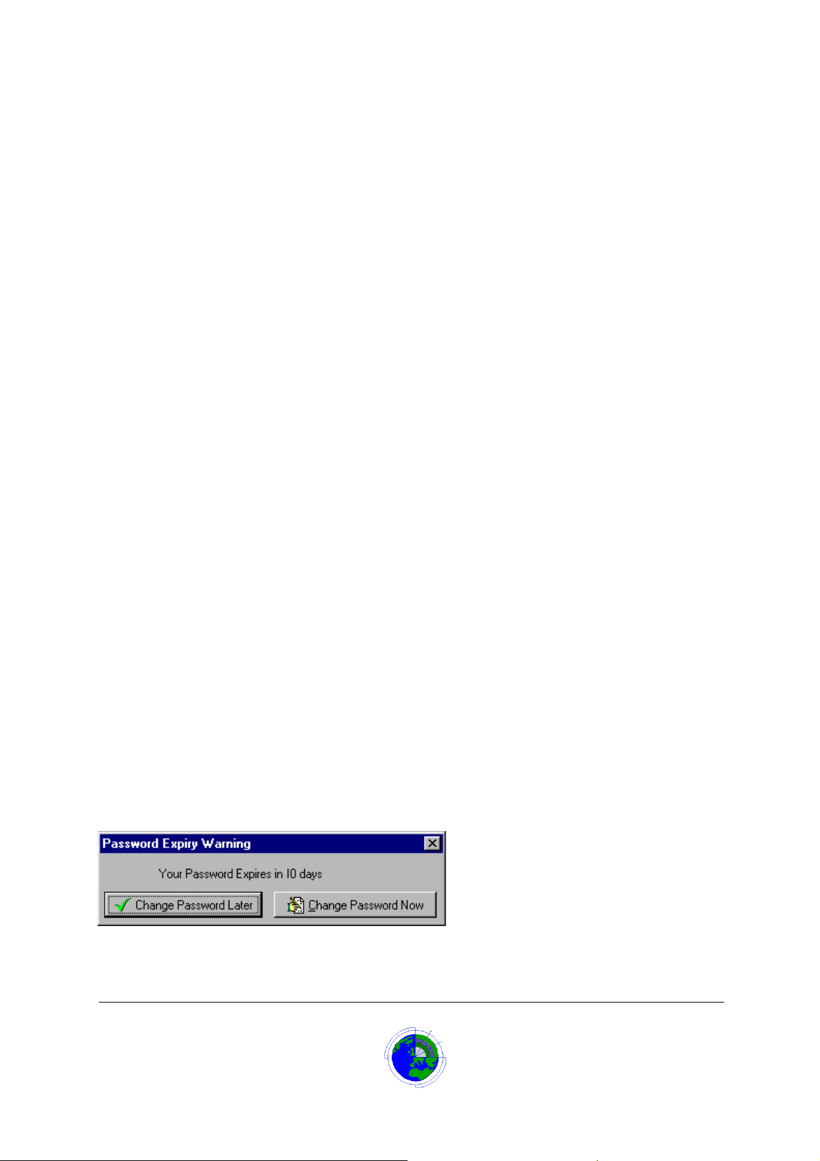
Task Bar Enabled
The Task bar enabled option on the User Setup Screen will enable the Windows 95 Task Bar.
It is recommended that the Datalog 3 system is run exclusively on a PC and that no non-Cortech
Developments applications are run at the same time. Cortech can not guarantee that other applications
will not affect communication with the field panels or other external hardware.
Because of this possibility, it is best to leave the task bar disabled. This will deter other users from
running any other applications.
Show Zone Numbers
If this option is checked in the ‘System’ ! ’User Setup’ dialog box, then the Datalog zone num ber will be
displayed and logged in front of any alarm text recorded and also shown in the icon hint text.
On some systems this number is not required as a more recognisable reference is used in the zone text.
If the Datalog zone number is not required remove the tick from this box.
Timed Alarm Analysis Printout
To set the Datalog 3 system to print an Alarm Analysis report at a specific time on a daily basis:
1. From the Main screen click ‘Log on’
The menu panel displays.
2. Select ‘System’ ! ’User Setup’.
The ‘User Setup’ dialog box displays.
3. Click the ‘Alarm Analysis Printout’ check box to tick.
4. Change the time to the required time for the print out.
To change the time which is in the format hh:mm:ss
5. Click on the ‘hh’ digits.
The hours digits are highlighted
Either:
6. Use the arrow keys on the right to increment/decrement the hours
Or
Overtype with the new hours
Repeat steps 1 and 2 for minutes and seconds digits
The printout format depends on the settings made when last running the Alarm Analysis report
manually.
Password Expiry Wa rn in g
The Password Expiry Warning field allows the operator to insert the number of days, before a password
expires, that a warning message is displayed. The message informs the user that his/her password will
expire in XX days and offers the choice of changing the password now or continuing with the current
password.
Datalog 3 User Manual - Page 41 of 66
CORTECH DEVELOPMENTS LTD
Page 42

Logging Printer
The User Setup screen allows the user to define a logging printer. That is a printer that can give a real
time printout of the events occurring on the Datalog 3 system.
To set up a logging printer:
1. Log on
The menu panel displays.
2. Select ‘System’ ! ’User Setup’.
The ‘User Setup’ dialog box displays.
3. Click the ‘Printer Setup’ ‘Logging Printer’ check box.
The ‘check box is ticked.
4. Click the ‘Setup’ button and setup the printer as described in your Windows 95 manual.
5. Click the ‘Font’ button and select the font type and size required.
6. In the ‘Buffer Entries Before Printing’ field select how many entries are to be stored by the
Datalog system before printing occurs.
If the printer is a dot-matrix type printer then chose 1 entry and the printer will print every event.
If the printer is a laser printer then choosing 1 would mean 1 entry per page, it may be more suitable to
choose 60 in this instance which would mean printing one page full of 60 entries. The printer would not
strictly be real time but the option is more ‘environmentally pleasing’.
Virtual Walk Test Thresholds
The Datalog 3 system can manage the site’s zone testing by assisting with walk test procedures.
The User Setup screen allows the user to define the period of days the system will allow a zone to
operate without an alarm being received from that zone. Once that period expires, the system will
generate an alarm to annunciate that a walk test is required.
In addition the user can also set the number of days before the walk test alarm occurs that the system
should issue a warning mess age.
The information can also be reviewed in a Walk Test report, which is based on these settings.
To set these parameters:
1. Log on
The menu panel displays.
2. Select ‘System’ ! ’User Setup’.
The ‘User Setup’ dialog box displays.
3. Click the ‘Virtual Walk Test Thresholds’ ‘Warning Days’ field and enter the number of days
before the walk test alarm occurs, that the system should issue a warning message (the
default is 1 day).
4. Click the ‘Virtual Walk Test Thresholds’ ‘Alarm Days’ field and enter the number of days the
system will allow a zone to operate without an alarm being received before a walk test
alarm occurs (the default is 30 days).
User Setup Additional Buttons
Additional buttons on the User Setup screen can be assigned by Cortech Developments, depending on
the field panels and additional equipment. The Datalog 3 system can monitor and program a number of
hardware options such as CCTV systems, Radio Pagers, CCTV Frame Storage units and Access
Control units.
When these units are connected to the system additional software is installed and buttons made
available for the various programming aspects.
Datalog 3 User Manual - Page 42 of 66
CORTECH DEVELOPMENTS LTD
Page 43
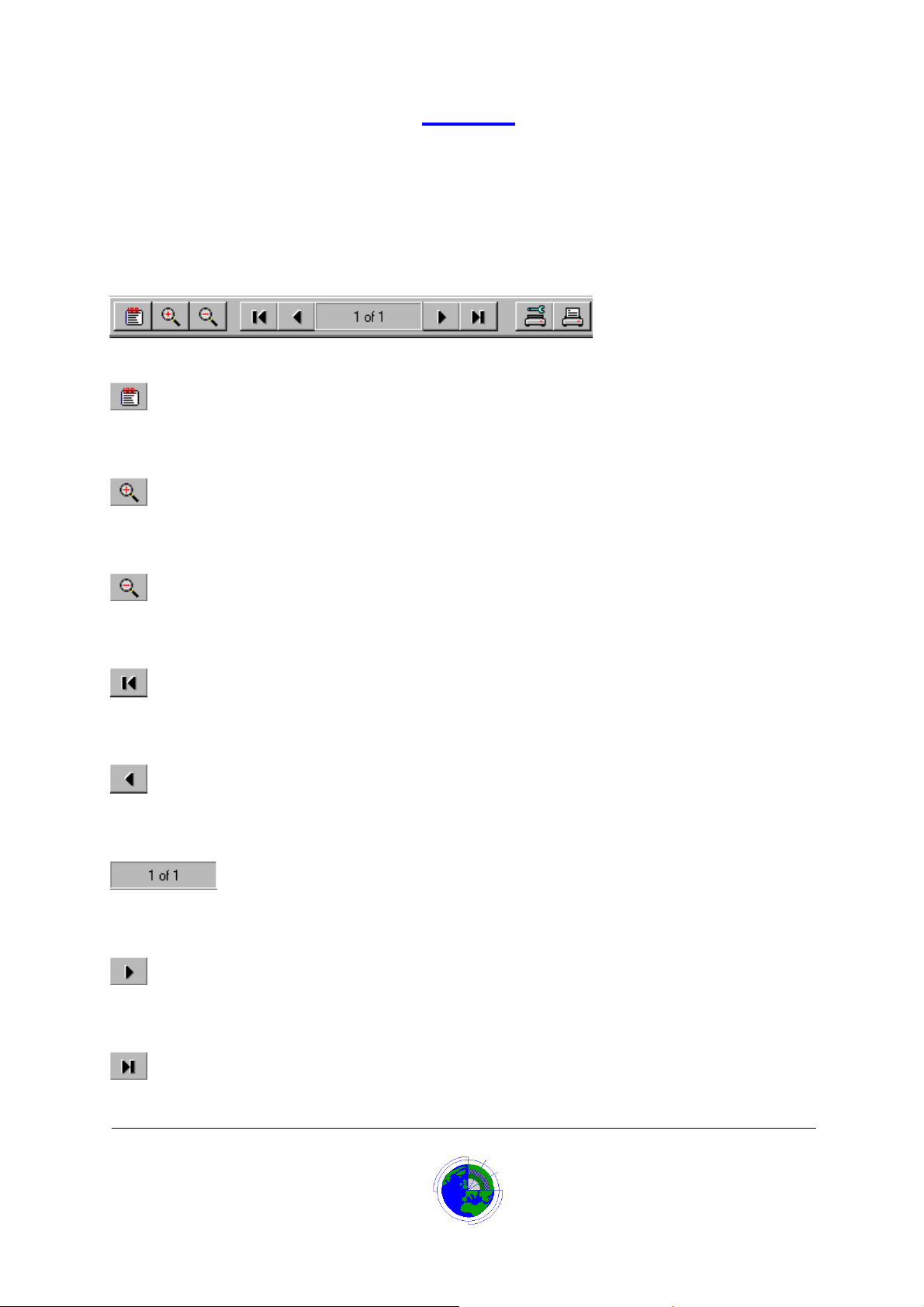
Reports
Report Button Bar
When a report is displayed, the report button bar allows the user to zoom in and out, and to move
between pages.
If a printed report is required, buttons allow the operator to set up the printer and to start printing.
Click on a button for more details.
Report 100% Button
The 100% button returns the displayed report to full size (100%) following a zoom in or out.
Report Zoom In Button
The ‘zoom in’ button allows the operator to zoom in (magnify) the displayed report.
Report Zoom Out Button
The ‘zoom out’ button allows the operator to zoom out (reduce the size) of the displayed report.
Report Go To Start Button
Clicking the ‘go to start’ button scrolls the report up to the start of the document.
Report Previous Page Button
Clicking the ‘previous page’ button scrolls the report up to the previous page of the document.
Report Page Status Window
The Page status window displays the current page number and the number of pages in the report.
Report Next Page Button
Clicking the ‘next page’ button scrolls the report down to the next page of the document.
Report Go To End Button
Clicking the ‘go to end’ button scrolls the report down to the end of the document.
Datalog 3 User Manual - Page 43 of 66
CORTECH DEVELOPMENTS LTD
Page 44
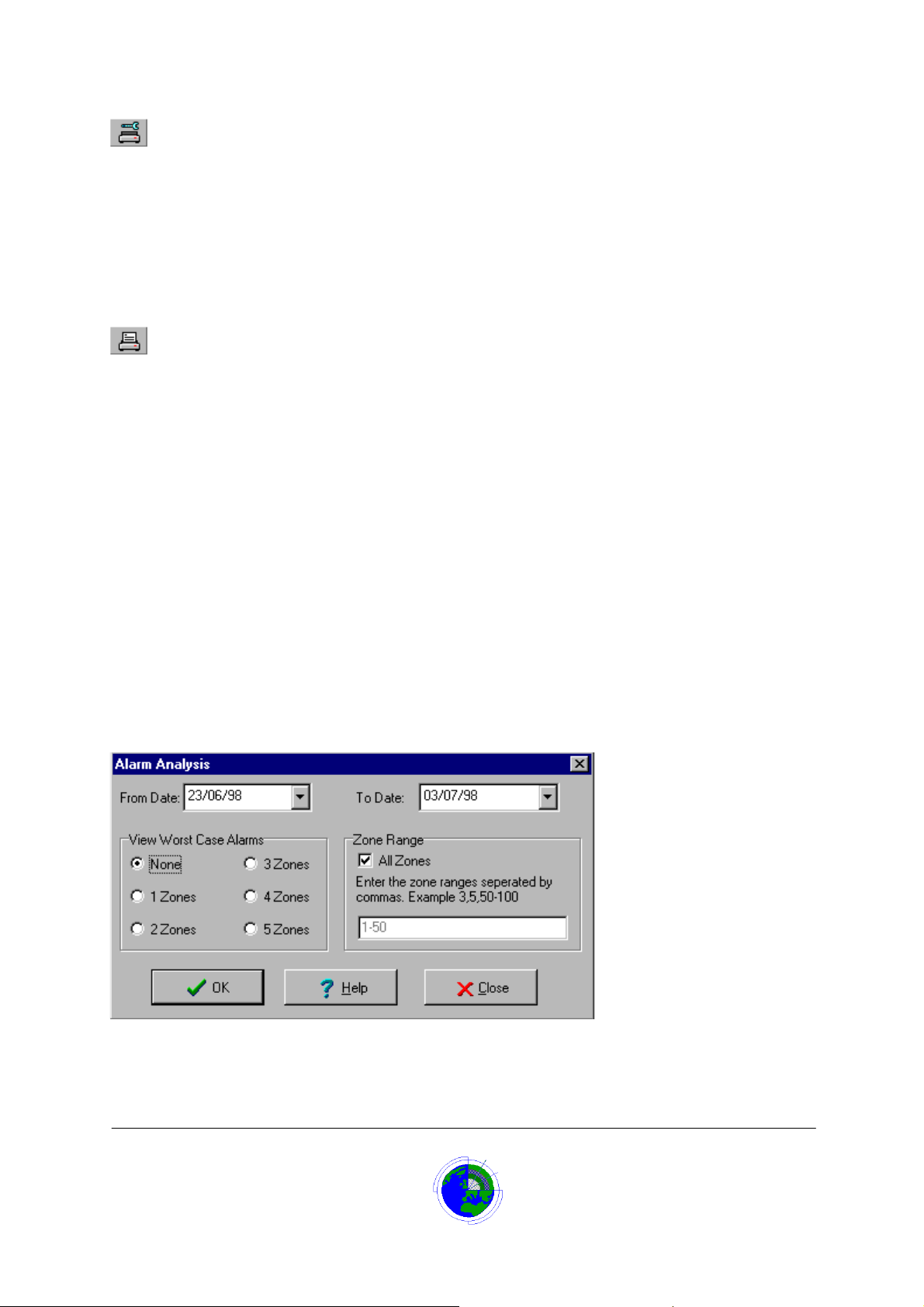
Report Printer Setup Button
The printer setup button launches the windows printer setup form to allow the user to select:
1. The printer
2. The paper
3. Paper orientation
4. Page(s) to print
5. Number of copies to be printed.
Report Print Button
The print button initiates the print operation according to the printer setup.
Ala rm Analysis R epo rt
The Alarm Analysis report allows the system manager to run a report, which will analyse the alarm
history for a selected period, then display a statistical report.
The report will give for each day from Monday to Sunday the alarm count on that day, the peak time for
alarms, the percentage of the total alarms received for the period.
It will also give for a selected number of zones, the most activated zone(s) how many alarm
occurrences on each day , Monday to Sunday, the total number of alarm occurrences for the period.
This report can also be set-up to run automatically at a specific time every day, using an option on the
‘User Setup’ Screen.
To run the alarm analysis report manually:
1. From the Main screen click ‘Log on’
The menu panel displays.
2. Select ‘Reports’ ! ‘Alarm Analysis’.
Or
Click the ‘Alarm Analysis Report’ button (button with the Graph icon)
The Alarm Analysis report setup screen displays.
3. In the ‘From Date’ field, type in the start date for the report or click the button on the right
and select the date from the calendar
Datalog 3 User Manual - Page 44 of 66
CORTECH DEVELOPMENTS LTD
Page 45

4. In the ‘To Date’ field, type in the end date for the report or click the button on the right, and
select the date from the calendar
5. In the View Worst Case Alarms section choose how many worst case alarms to analyse (0-
5) by clicking on the relevant radio button
6. In the Zone range panel, the default is for all zones but clicking on the All zones check box
will remove the tick and one or more zones can be selected by typing in the field below the
check box.
7. Once all selections have been made click the ‘OK’ button to run the report
The report is displayed on the screen. Options are available to set-up and print the report.
Alarm Analysis Report View Worst Case Alarms
In the View Worst Case Alarms section choose how many of the most activated zone(s) to analyse (0-5)
by clicking on the relevant radio button
The report will show for each of the worst case alarms, how many alarm occurrences on each day,
Monday to Sunday, and the total number of alarm occurrences for the period.
Report Zones Selection
This option allows the operator to choose which zone(s) to display on a report
By default the ‘All Zones’ check box is ticked so any reports will run for all zones.
If running a report where the Events field is set to Alarm Events, Inhibit Events or Disable & Soaks, the
operator can click to remove the tick from the ‘All Zones’ check box. The zones that information is
required for, must be entered in the field below the tick box.
The options for this field are:
If information is only required for a single zone enter just the zone number.
If information is required for several contiguous zones enter start zone then hyphen then
end number e.g. 8-15
If information is required on several non-contiguous zones enter the zone numbers
separated by commas e.g. 2,6,9,14,25
It is also possible to mix contiguous and non-contiguous numbers e.g. 6,9,12-18,25
Database History Report
Any occurrences of alarms, system warnings, user actions to accept and reset alarms, user changes to
the system are all time and date stamped, and stored in the history database of the Datalog 3.
The Database History report allows the user to retrieve this information for a period that can be selected
by the operator.
To run the Database History Report:
1. From the Main screen click ‘Log on’
The menu panel displays.
2. Select ‘Reports’ ! ‘Review Database’.
Or
Click the ‘Database History Report’ button (button with the log book icon)
The Alarm Database report setup screen displays.
Datalog 3 User Manual - Page 45 of 66
CORTECH DEVELOPMENTS LTD
Page 46
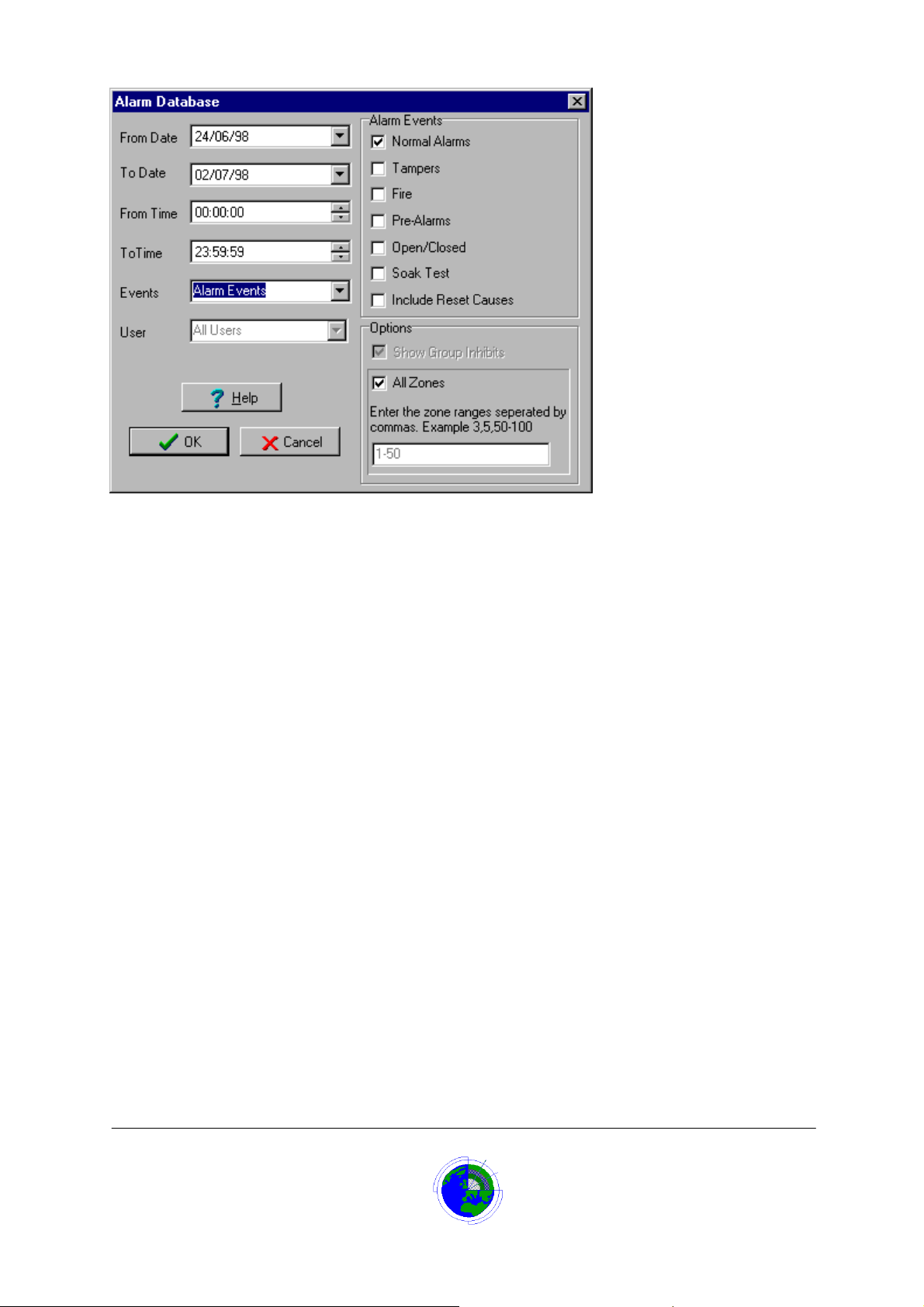
By default the Alarm Database report setup will select all history events for the current day. To modify
the settings:
1. In the ‘From Date’ field, type in the start date for the report or click the button on the right and select
the date from the calendar
2. In the ‘To Date’ field, type in the end date for the report or click the button on the right, and select the
date from the calendar.
3. In the ‘From Time’ field, click and type in or use the count up/down buttons to change the hours,
minutes and seconds to the start time for each day selected that the report should start from.
4. In the ‘To Time’ field, click and type in or use the count up/down buttons to change the hours,
minutes and seconds to the end time for each day selected that the report should end at.
5. In the Events field select the type of events to report, from the list:
Alarm Events Select this if just alarm event information is required. Additionally, in the Alarm
Event check boxes, the operator can choose whether to include: Normal
Alarms, Tamper alarms, Fire Alarms, Pre-Alarms, Alarm Contact Open/Closed
times, Soak Test Alarms, and to include reset Cause information
Faults and Warnings Displays any fault alarms and warning messages that have occurred for
the period elected.
Inhibit Events Displays any inhibit operations for the period. The ‘User’ field allows viewing
inhibits by all users or a specific user. The default is for all zones but clicking on
the All zones check box will remove the tick and one or more zones can be
selected by typing in the field below the check box.
Disables & Soaks Displays any Engineering disable or soak test operations that have occurred for
the period. The ‘User’ field allows viewing inhibits by all users or a specific user.
The default is for all zones but clicking on the All Zones check box will remove
the tick and one or more zones can be selected by typing in the field below the
check box.
System Events Displays information on any changes that take place on the system such as
password edits, Time Zone start and end messages, Program termination. The
‘User’ field allows viewing events caused by all users or a specific user.
All Events Displays all events for the selected period.
Datalog 3 User Manual - Page 46 of 66
CORTECH DEVELOPMENTS LTD
Page 47

6. Once all selections have been made click the ‘OK’ button to run the report
The report is displayed on the screen. Options are available to set-up and print the report.
Report From Date
In the ‘From Date’ field, enter the date that the report is to display information from. The default is the
current date.
The date is in the format dd/mm/yy
To enter the date either:
1. Click on the ‘dd’ digits
The day digits are highlighted
2. Overtype with the new day digits
3. Repeat above for ‘mm’ and ‘yy’ digits
Or
4. Click arrow button to right of date and select the date from the calendar
Report To Date
In the ‘To Date’ field, enter the last date that the report is to display information for. The default is the
current date.
The date is in the format dd/mm/yy
To enter the date either:
1. Click on the ‘dd’ digits
The day digits are highlighted
2. Overtype with the new day digits
3. Repeat above for ‘mm’ and ‘yy’ digits
Or
4. Click arrow button to right of date and select the date from the calendar
Alarm Database Report From Time
In the ‘From Time’ field, enter the time that the report is to display information from on each selected
day. The default is 00:00
To change the time which is in the format hh:mm:ss
1. Click on the ‘hh’ digits.
The hours digits are highlighted
Either:
2. Use the arrow keys on the right to increment/decrement the hours
Or
Overtype with the new hours
3. Repeat steps 1 and 2 for minutes and seconds digits
Alarm Database Report To Time
In the ‘To Time’ field, enter the ending time that the report is to display information on each selected
day. The default is 23:59:59
To change the time which is in the format hh:mm:ss
1. Click on the ‘hh’ digits.
The hours digits are highlighted
Either:
2. Use the arrow keys on the right to increment/decrement the hours
Or
Datalog 3 User Manual - Page 47 of 66
CORTECH DEVELOPMENTS LTD
Page 48

Overtype with the new hours
3. Repeat steps 1 and 2 for minutes and seconds digits
Alarm Database Report Event Field
The Events field allows the operator to select the type of events to report, from a list.
The options are:
Alarm Events Select this option if just alarm event information is required. Additionally, in the
Alarm Event check boxes, the operator can choose whether to include: Normal
Alarms, Tamper Alarms, Fire Alarms, Pre-Alarms, Alarm Contact Open/Closed
times, Soak Test Alarms, and to include reset Cause information
Faults and Warnings Displays any fault alarms and warning messages that have occurred for the
period selected.
Inhibit Events Displays any inhibit operations for the period. The ‘User’ field allows viewing
inhibits by all users or a specific user. The default is for all zones but clicking on
the All Zones check box will remove the tick and one or more zones can be
selected by typing in the field below the check box.
Disables & Soaks Displays any Engineering disable or soak test operations that have occurred for
the period. The ‘User’ field allows viewing inhibits by all users or a specific user.
The default is for all zones but clicking on the All Zones check box will remove
the tick and one or more zones can be selected by typing in the field below the
check box.
System Events Displays information on any changes that take place on the system such as
password edits, Time Zone start and end messages, Program termination. The
‘User’ field allows viewing events caused by all users or a specific user.
All Events Displays all events for the selected period.
Alarm Database Report User Field
If the Event field is set for either Inhibit Events, Disable and Soak Test events or System Events, then
the User field is enabled. The operator can then choose either to display the events that involved all
users (the default) or select a Users name from the list. The displayed report will then only display the
events that occurred while that user was logged on.
Alarm Database Report Alarm Event
This option allows the operator to choose the type of alarms to display on the History Database report
If the Event field has been set to ‘Alarm Events’, the Alarm Event check boxes are enabled. The
operator can then tick the type of alarms to be displayed. The options are: Normal Alarms, Tamper
Alarms, Fire Alarms, Pre-Alarms, Alarm Contact Open/Closed times, and Soak Test Alarms.
The last check box, ‘Include Reset Causes’, enables reset information to be displayed with the cause. If
this box is not checked the report will only display when alarms were activated and not when they were
reset.
Alarm Database Report Options Field
This check box is enabled when the Events field is set to display ‘Inhibit Events’. The default is that this
check box is ticked and when the report is run for ‘Inhibit Events’ both single zone and group inhibit
changes are shown. If the operator clicks on the check box to remove the tick, the report, when run, will
show only single zone inhibits and not group inhibits.
Datalog 3 User Manual - Page 48 of 66
CORTECH DEVELOPMENTS LTD
Page 49

Time Zone Report
To run a time zone report to screen or printer:
1. From the Main screen click ‘Log on’
The menu panel displays.
2. Select ‘System’ ! ’User Setup’.
The ‘User Setup’ dialog box displays.
3. Click the ‘Setup Automatic TimeZones’ button.
The ‘Time Zone Form’ displays.
4. Click the ‘Print’ button.
The time zone report is displayed on the screen.
User Report
To display an existing system users details:
1. From the Main screen click ‘Log on’
The menu panel displays.
2. Select ‘Password’ ! ’Edit Password’.
The ‘Master Password Setup ’ dialog box displ a ys.
3. Click the ‘Print’ button
The User report is displayed on the screen. Options are available to set-up and print the report.
Walk Test Report
The Walk Test Report allows the user to print a list of the zones requiring a Walk Test. The report is the
same list as is displayed at the bottom of the Map Viewer screen when the ‘Options’ radio button is set
to ‘Walk Test’. This gives Zone number, Description, Warning Threshold, and Days since Walk Test.
To run the report:
1. From the Main screen click ‘Log on’
The menu panel displays.
2. Select ‘Reports’ ! ‘Walk Test Report’.
Or
Click the ‘Walk Test Report’ button (butt on with the pa ge + 2 peopl e icon)
The Walk Test report displays, options are available to print the report.
Datalog 3 User Manual - Page 49 of 66
CORTECH DEVELOPMENTS LTD
Page 50

Datalog 3 User Manual - Page 50 of 66
CORTECH DEVELOPMENTS LTD
Page 51
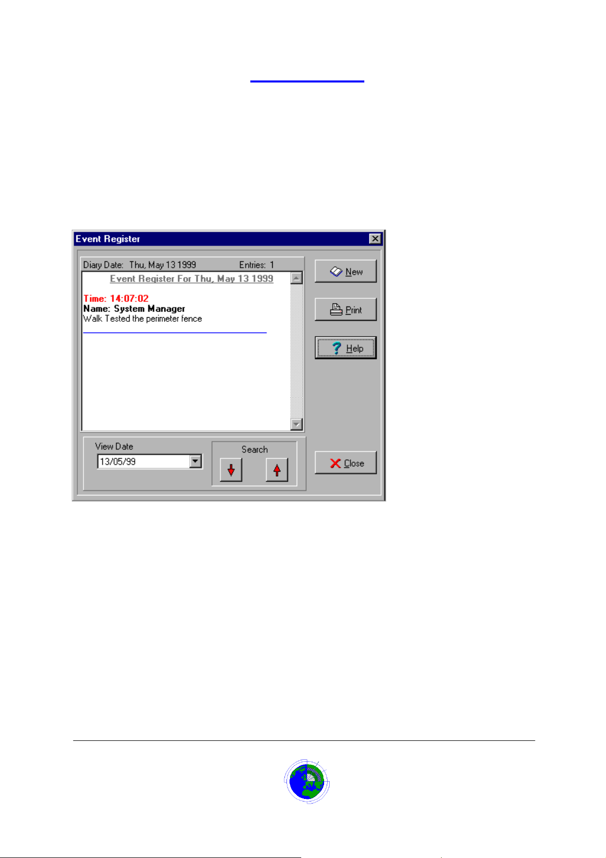
Event Register
The Event Register is a diary type log book that allows the operator to log events that are not
automatically stored in the Datalog’s history. Events entered are automatically stored at the system date
and time, and should be input at the time of occurrence.
To log an event:
1. From the Main screen click ‘Log on’
The menu panel displays.
2. Select ‘Reports’ ! ‘Event Register’.
Or
Click the ‘Event Register’ button (button with the notepad icon)
The Event Register screen displays.
3. Click the ‘New’ button
The New Entry text box displays
4. Type in the entry text
5. Click the ‘Save’ button
The entry is stored in the event register diary at the current system date. The entry time and logged-on
username are added to the entry automatically.
Viewing the Event Register
The Event Register can be viewed by:
From the Main screen click ‘Log on’
The menu panel displays.
1. Select ‘Reports’ ! ‘Event Register’.
Or
2. Click the ‘Event Register’ button (button with the notepad icon)
Datalog 3 User Manual - Page 51 of 66
CORTECH DEVELOPMENTS LTD
Page 52

The Event Register screen displays.
3. Select the date to view by:
Click the up or down red arrow buttons to move the calendar up or down a day
Click on the arrow to the right of the ‘View Date’ field
Select date in Windows ’95 type calendar
The selected days events will display.
If a printout is required:
1. Click the ‘Print’ button.
The selected days events will be printed.
Datalog 3 User Manual - Page 52 of 66
CORTECH DEVELOPMENTS LTD
Page 53
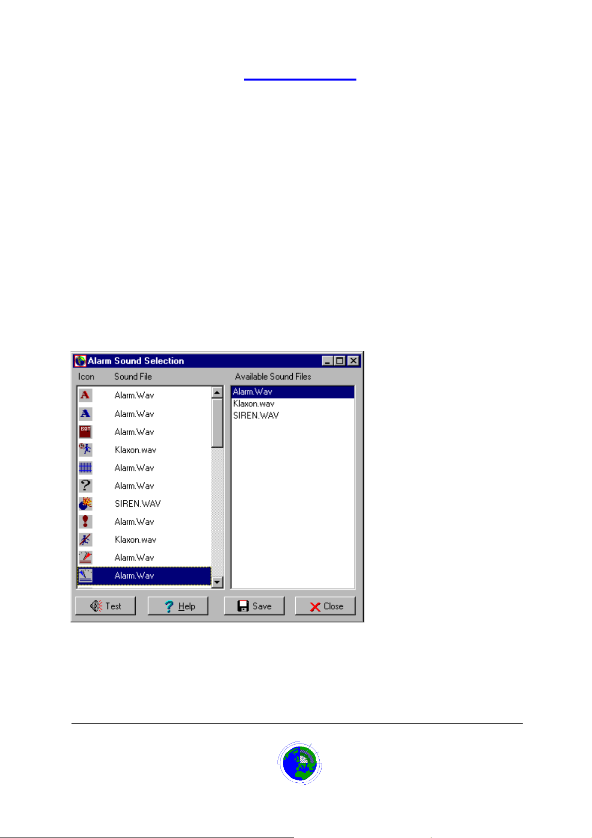
Alarm Sounds
The Datalog system has 40 different icons, the icons are assigned to map positions during installation,
and a different icon is used for each type of alarm sensor.
Initially all icons are assigned the standard alarm sound, Alarm.Wav.
It is possible to assign different alarm sounds to each icon type. This means a different sound may be
generated at a PIR sensor than at a door contact.
Datalog 3 provides a number of standard sounds. In addition, if the equipment is available, the system
user can generate sounds and assign them to the system.
The Alarm Sounds Selection form, accessed from User Setup, enables the operator to assign a sound
file to each icon type.
Assigning Alarm Sounds
To assign an alarm sound file to an icon type:
1. From the Main screen click ‘Log on’
The menu panel displays.
2. Select ‘System’ ! ’User Setup’.
The ‘User Setup’ dialog box displays.
3. Click the ‘Alarm Sounds’ button.
The ‘Alarm Sound Selection’ dialog box displays.
1. Scroll down and click on the relevant icon
The icon and its current sound file are highlighted
2. Click on the desired sound file in the ‘Available Sound Files’ list
The sound file is assigned to the icon.
3. Click the ‘Save’ button to store the change.
4. Click the ‘Test’ button to check the sound.
Datalog 3 User Manual - Page 53 of 66
CORTECH DEVELOPMENTS LTD
Page 54

Generating Alarm Sounds
If more sounds are required these can be generated using commercially available equipment.
There are many sound cards available from most personal computer stockists. Included with the sound
card is software that can generate and play back sounds. In addition, microphones are available to plug
in to the sound card so that spoken messages can be recorded.
The sound should be stored in a file using the ‘Wav’ file format.
To include the sound in the Datalog 3 system, copy the Wav file to the Data directory, and assign it to an
alarm
Datalog 3 User Manual - Page 54 of 66
CORTECH DEVELOPMENTS LTD
Page 55
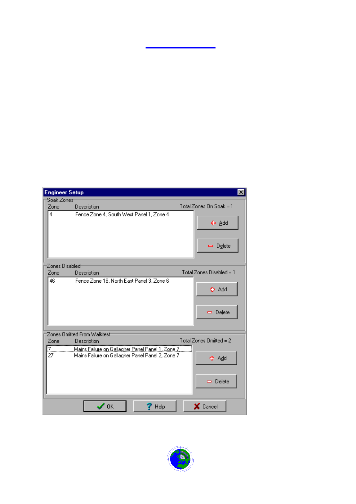
Engineer Setup
The engineer setup option is generally used during installation of alarm sensors or when a sensor is
faulty. Four functions are provided for the engineer.
1. To put a zone on soak test
2. To remove a zone from soak test.
Any zones on the system can be placed on soak test. When a zone is on soak test and activated it will
not generate an alarm condition, but the activation will be logged as an event in the system log. If zones
are dynamically displayed on a map, a soak zone will display as a green icon.
3. To disable a zone
4. To re-instate a disabled zone.
An engineer can disable any zones on the system. Normally this would be used if a sensor was faulty
and giving false alarms or a zone had been programmed on the system but not yet installed. If zones
are dynamically displayed on a map, a disabled zone will display as a Maroon Icon
5. To omit a zone from walk test
6. To re-instate a zone for Walk Test
It may not be possible for site staff to walk test some zones, they may be inaccessible without special
knowledge or equipment, such as equipment failure and tamper alarms. This option is available to omit
and re-instate alarms from the walk test.
Datalog 3 User Manual - Page 55 of 66
CORTECH DEVELOPMENTS LTD
Page 56

Putting a zone on Soak
To place a zone on soak:
1. On the Menu Panel select System !Engineer Setup
2. Click the top Add button.
A list of all zones will display in numeric order.
If preferred the zones may be viewed in alphabetic order by pressing the sort button.
3. Select and highlight the relevant zone.
4. Click the OK button.
The zone number and description will be entered in the Soak Zone list.
5. Click OK button on Engineer Setup window.
Removing a Zone from Soak Test
To remove a zone from soak:
1. On the Menu Panel select System !Engineer Setup
A list of all zones on soak will display in numeric order in the ‘Soak Zone’ list.
2. Select and highlight the relevant soak zone to remove.
3. Click the top Delete button.
The zone number and description will be deleted from the Soak Zone list.
4. Click OK button on Engineer Setup window.
Disabling a Zone
To disable a zone:
1. On the Menu Panel select System !Engineer Setup
2. Click the middle Add button.
A list of all zones will display in numeric order.
If preferred the zones may be viewed in alphabetic order by pressing the sort button.
3. Select and highlight the relevant zone.
4. Click the OK button.
The zone number and description will be entered in the Disabled Zones list.
5. Click OK button on Engineer Setup window.
Re-instating a Disabled Zone
To re-instate a disabled zone:
1. On the Menu Panel select System !Engineer Setup
A list of all disabled zones will display in numeric order in the ‘Zones Disabled’ list.
2. Select and highlight the relevant zone to re-instate.
3. Click the middle Delete button.
The zone number and description will be deleted from the Disabled Zone list.
4. Click OK button on Engineer Setup window.
Datalog 3 User Manual - Page 56 of 66
CORTECH DEVELOPMENTS LTD
Page 57

Modem Support
Cortech Developments offer a technical support service for the Datalog 3 system via modem
connection.
If the option for support has been requested, the Datalog 3 installation will include an internal modem
and a copy of PCAnywhere communication software to provide the online support functions.
For security purposes the online connection is initiated from the Datalog 3 system and it is not possible
for anyone to dial in without arranging it with the system operator.
When the support is arranged, a phone number will be provided which will have to be entered by the
operator.
To initiate modem support:
1. From the Main screen click ‘Log on’
The menu panel displays.
2. Select ‘System’ ! ‘Modem Support’.
Or
Click the ‘Modem Support’ button (button with the telephone icon)
A confirmation dialog box displays.
3. Click the ‘OK’ button.
After a few seconds, a ‘PCAnywhere Waiting’ dialog box displays.
4. Enter the phone number to contact Cortech remote support.
If the phone line is an extension of the internal phone system the number may have to be preceded
with 9, (that is nine followed by a comma then the phone number)
5. Click ‘OK’
The modem in the PC should then dial out and the connection made.
Datalog 3 User Manual - Page 57 of 66
CORTECH DEVELOPMENTS LTD
Page 58

Datalog 3 User Manual - Page 58 of 66
CORTECH DEVELOPMENTS LTD
Page 59

Quitting Datalog 3
To close the Datalog 3 system:
1. Log on
The menu panel displays.
2. Select ‘System’ ! Quit Datalog’.
The ‘Quit Datalog’ confirmation box displays.
3. Click ‘OK’
The program will then close down and return to Windows’95.
To switch the computer off:
1. Click ‘Start’ on the Task bar and ‘Shut Down’ on the menu
Or
Press Alt and F4 function key simultaneously.
2. Click ‘OK’ button and switch off when screen displays message to do so.
Datalog 3 User Manual - Page 59 of 66
CORTECH DEVELOPMENTS LTD
Page 60

Datalog 3 User Manual - Page 60 of 66
CORTECH DEVELOPMENTS LTD
Page 61
Cortech Developments
CORTECH
DEVELOPMENTS LTD
‘Specialist Software & Systems Solutions’
Cortech Developments was established in 1992 following a successful testing and development
program for the original version I, Datalog software. Since then there have been many enhancements to
the system software and now Datalog 3, running on the Windows 95
cost-effective series of package solutions for a wide variety of systems and applications.
Our aim is to provide a comprehensive control facility with the capability to interface and interact with a
wide range of different manufacturers control equipment including; Security, Fire, CCTV, Access Control
and Building System s.
Many of the unique features included within our range of software solutions have been developed from a
combination of practical experience and special requests by our customers, to develop specific
programs to deal with a variety of security environments, risks and working practices.
We can offer a wide range of software, equipment software and integration.
Datalog 3 User Manual - Page 61 of 66
TM
operating system, offers a very
CORTECH DEVELOPMENTS LTD
Page 62

Contacting Cortech Developments
Cortech Developments Ltd.
The Barn, Laskey Farm,
Laskey Lane,
Thelwall,
Warrington,
Cheshire.
WA4 2TF
Telephone: 44 (0)1925 750600
Fax: 44 (0)1925 750601
Datalog 3 User Manual - Page 62 of 66
CORTECH DEVELOPMENTS LTD
Page 63

Index
A
Additional Buttons.......................................................................................................................... 13
Alarm Cause Dialog Box................................................................................................................ 15
Alarm Logging................................................................................................................................ 18
Alarm Operated Output.................................................................................................................. 24
Alarm Queue.................................................................................................................................. 16
Alarm Sounds ................................................................................................................................ 55
Assigning.................................................................................................................................... 55
Generating.................................................................................................................................. 56
C
Cortech Developments
About.......................................................................................................................................... 63
D
Datalog III......................................................................................................................................... 5
Date Setting ................................................................................................................................... 40
E
Engineer Setup .............................................................................................................................. 57
Enter Alarm Cause......................................................................................................................... 41
Event Help Button.......................................................................................................................... 12
Event Register ............................................................................................................................... 53
Viewing....................................................................................................................................... 53
Exiting the Datalog III system ........................................................................................................61
F
F1 Key............................................................................................................................................ 12
F10 Key.......................................................................................................................................... 13
F2 Key............................................................................................................................................ 12
F4 Key............................................................................................................................................ 12
F9 Key............................................................................................................................................ 13
Follow Latest Alarm ....................................................................................................................... 41
G
Group Inhibit Button....................................................................................................................... 13
H
Handling Alarm Events .................................................................................................................. 15
I
Icon Display.............................................................................................................................. 30, 31
Icons............................................................................................................................................... 14
Blue Icon..................................................................................................................................... 13
Green Icon.................................................................................................................................. 14
Grey Icon.................................................................................................................................... 14
Maroon Icon ............................................................................................................................... 14
Red Icons ................................................................................................................................... 14
Datalog 3 User Manual - Page 63 of 66
CORTECH DEVELOPMENTS LTD
Page 64

Yellow Icon................................................................................................................................. 14
L
Last Events Window ...................................................................................................................... 11
Log On Button................................................................................................................................ 13
M
Main Screen................................................................................................................................... 11
Accept Button............................................................................................................................. 12
Event Help Button ...................................................................................................................... 12
Log On Button ............................................................................................................................13
Manual Output Control................................................................................................................... 24
Map Icons ...................................................................................................................................... 13
Blue Icon..................................................................................................................................... 13
Green Icon.................................................................................................................................. 14
Grey Icon.................................................................................................................................... 14
Maroon Icon ............................................................................................................................... 14
Red Icon..................................................................................................................................... 14
Yellow Icon................................................................................................................................. 14
Map Viewer.................................................................................................................................... 31
Icon Display................................................................................................................................ 30
Map Selection Box ..................................................................................................................... 30
Map Viewer Button..................................................................................................................... 13
Map Viewer Screen.................................................................................................................... 30
Options....................................................................................................................................... 31
Walk Test Options...................................................................................................................... 31
Master Password Setup Screen....................................................................................................34
Days to Expiry ............................................................................................................................ 36
Name.......................................................................................................................................... 35
Password.................................................................................................................................... 35
Title.............................................................................................................................................35
User Access Level...................................................................................................................... 36
User List ...................................................................................................................... ...............35
Modem Support ............................................................................................................................. 59
Multiple Alarms .............................................................................................................................. 17
O
Omit Zones from Walk Test........................................................................................................... 32
Outputs........................................................................................................................................... 24
Time Zone Operated ..................................................................................................................25
P
Password to Accept an Alarm........................................................................................................ 41
Passwords ..................................................................................................................................... 34
A Password ................................................................................................................................ 34
Changing Your Own Password.................................................................................................. 37
R
Re-instate Walk Test Zone ............................................................................................................32
Report ............................................................................................................................................51
100% button ............................................................................................................................... 45
Alarm Analysis............................................................................................................................ 46
Database History Report............................................................................................................ 47
Go To End Button....................................................................................................................... 45
Go To Start Button ..................................................................................................................... 45
Next Page Button .......................................................................................................................45
Datalog 3 User Manual - Page 64 of 66
CORTECH DEVELOPMENTS LTD
Page 65

Page Status Window.................................................................................................................. 45
Previous Page Button................................................................................................................. 45
Print Button................................................................................................................................. 46
Printer Setup Button................................................................................................................... 46
Time Zone .................................................................................................................................. 51
Walk Test ................................................................................................................................... 51
Zoom In Button........................................................................................................................... 45
Zoom Out Button........................................................................................................................ 45
Report Button Bar .......................................................................................................................... 45
Reset Button .................................................................................................................................. 12
S
Show Dynamic Display.................................................................................................................. 41
Show Zone Numbers ..................................................................................................................... 42
Single Zone Inhibit .........................................................................................................................19
T
Time Setting................................................................................................................................... 39
Time Zone...................................................................................................................................... 26
Adding ........................................................................................................................................ 28
Deleting ......................................................................................................................................29
Displaying................................................................................................................................... 29
Editing......................................................................................................................................... 28
Report......................................................................................................................................... 51
Time Zone Form......................................................................................................................... 26
Time Zone Form ............................................................................................................................ 26
Action List................................................................................................................................... 27
Description ................................................................................................................................. 26
Group List................................................................................................................................... 27
Monday-Sunday .........................................................................................................................27
Time Off...................................................................................................................................... 27
Time On...................................................................................................................................... 27
U
User Setup..................................................................................................................................... 39
Additional Buttons ...................................................................................................................... 43
Logging Printer........................................................................................................................... 43
Password Expiry Warning.......................................................................................................... 42
Setup Automatic Time Zones Button ......................................................................................... 41
Task Bar Enabled....................................................................................................................... 42
Timed Alarm Analysis Printout...................................................................................................42
Virtual Walk Test Thresholds .....................................................................................................43
Users of the system ....................................................................................................................... 34
Adding ........................................................................................................................................ 36
Changing Your Password........................................................................................................... 37
Deleting ......................................................................................................................................37
Displaying................................................................................................................................... 37
Editing User details .................................................................................................................... 36
User Report................................................................................................................................ 51
W
Walk Test....................................................................................................................................... 32
Z
Zone............................................................................................................................................. 7, 8
Disabling a Zone ........................................................................................................................ 58
Datalog 3 User Manual - Page 65 of 66
CORTECH DEVELOPMENTS LTD
Page 66

Group Enable .............................................................................................................................21
Group Inhibit............................................................................................................................... 21
Putting a Zone on Soak Test...................................................................................................... 58
Re-instating a Disabled Zone..................................................................................................... 58
Removing a Zone from Soak Test ............................................................................................. 58
Single Zone Enable.................................................................................................................... 19
Zone Enable................................................................................................................................. 9
Zone Inhibit............................................................................................................................. 9, 19
Zone Inhibit ....................................................................................................................................20
Group Inhibit List ........................................................................................................................21
Zone Inhibit Button .....................................................................................................................13
Zone Inhibit List.......................................................................................................................... 20
Zone Inhibit Screen ....................................................................................................................20
Zone Inhibit Timer ...................................................................................................................... 22
Datalog 3 User Manual - Page 66 of 66
CORTECH DEVELOPMENTS LTD
 Loading...