

Page 1

EMAIL: support@corsair.com
WEB: corsair.com
BLOG: corsair.com/blog
FORUM: forum.corsair.com
USA and CANADA: (510) 657-8747 | INTERNATIONAL: (888) 222-4346 | FAX: (510) 657-8748
corsair.com
FACEBOOK: facebook.com/Corsair
TWITTER: twitter.com/Corsair
YOUTUBE: youtube.com/Corsair
SP RGB SERIES
INSTALLATION GUIDE
GUIDE D’INSTALLATION
INSTALLATIONSANLEITUNG
GUIDA ALL’INSTALLAZIONE
GUÍA DE INSTALACIÓN
РУКОВОДСТВО ПО УСТАНОВКЕ
GUIA DE INSTALAÇÃO
安装指南
インストールガイド
47100 Bayside Parkway • Fremont, California 94538 • USA | corsair.com
© 2016 Corsair Components, Inc. All Rights Reserved. The Corsair logo is a registered trademark, and Hydro Series are
trademarks of Corsair in the United States and/or other countries. All other names and products are trademarks and
property of their respective owners. Printed in China.
Document Number: 49-001502 rev AA
SP120 RGB
PERFORMANCE FANS WITH CUSTOMIZABLE LIGHTING MODES AND COLORS
Page 2

Page 3

English .............................................. –
Français ..........................................–
Italiano ......................................... –
Deutsch ........................................ –
Español ........................................ –
Россию ........................................... –
Português ................................... –
中文 ................................................ –
日本語 ............................................ –
Page 4
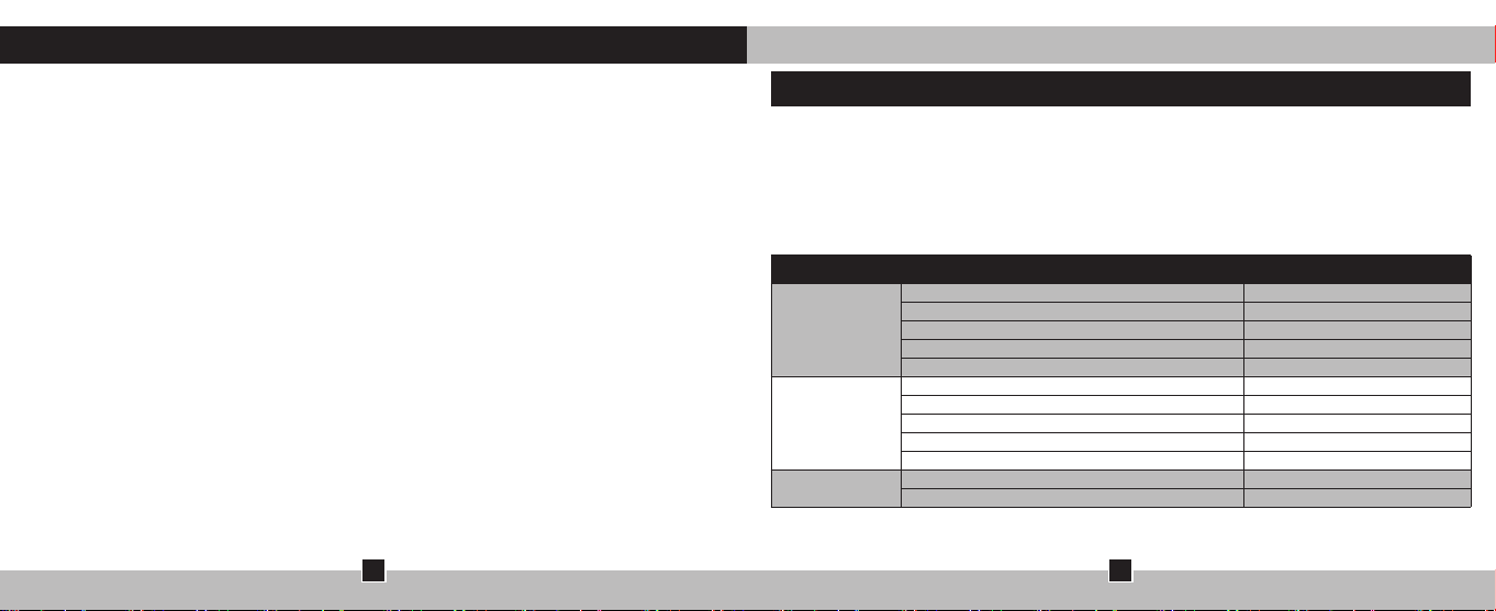
Table of Contents
SP120 RGB FAN
Congratulations: .....................................................................................................................................
SPRGBSeriesFeatures: .....................................................................................................................
Installation: ...............................................................................................................................................
InstallationContinued: ........................................................................................................................
OptionalInstallation: ............................................................................................................................
1
Congratulations
The CORSAIR SP RGB series of fans gives you high performance and RGB LED lighting
in one package.
SP RGB Kit Contents
Fans 3
Fan Hub 1
Three fan Kit
Single Fan Kit
Single Fan
Fan Controller 1
Mounting Screws 12
Mounting Strips 2
Fan 1
Fan Hub 1
Fan Controller 1
Mounting Screws 4
Mounting Strips 2
Fan 1
Mounting Screws 4
2
Page 5
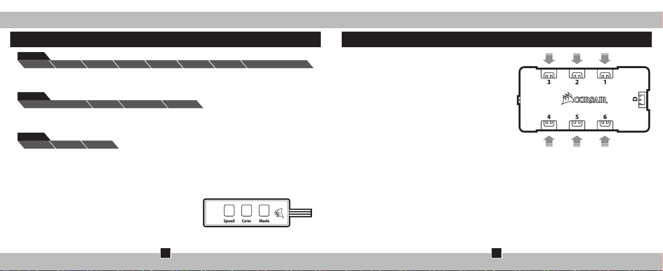
COLOR
White Red Orange Yellow Green Blue Violet W>R>O>Y>G>B>V
> Color Selection – White > Red > Orange > Yellow > Green >
Blue > Violet > Cycle through all colors > return to beginning.
MODE
StaticBreathing & Flicker Breathing Flicker
> Mode Selection – Breathing & Flicker > Static >
Breathing > Flicker > Return to beginning.
SPEED
High Medium Slow
> Speed Selection – High > Medium > Slow > Return to Beginning.
1. Once all items are connected properly and powered on simply press the button of
the corresponding option you would like to change once in order to move forward in
the selection cycle.
2. The buttons are labeled on the fan controller itself.
a. Color = Color Selection
b. Mode = Mode selection
c. Speed = Speed Selection
SP120 RGB FANSP120 RGB FAN
InstallationSP RGB Series Features
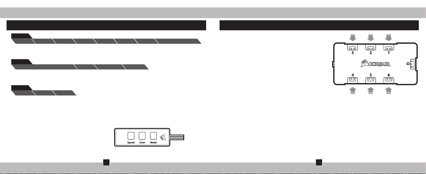
> Connection Notes
• The Fan LED wiring must be connected
to the fan hub in the order you want the
lighting eects to be displayed.
• Fans must start at “1” and continue in
series. 1 > 2 > 3 > 4 > 5 > 6
• Any fan not connected in series will break
communication and the RGB LED lighting
function will not work.
> Mount the fan(s) to the location
of your choice in the chassis.
> Find a location for the fan hub that allows
connection for all of the fans RGB LED cables
installed in your system to reach.
• The fan controller will also need to be
plugged into the fan hub for control of the
RGB LED lighting.
> Mount the fan hub with the provided
mounting strips.
3
4
Page 6
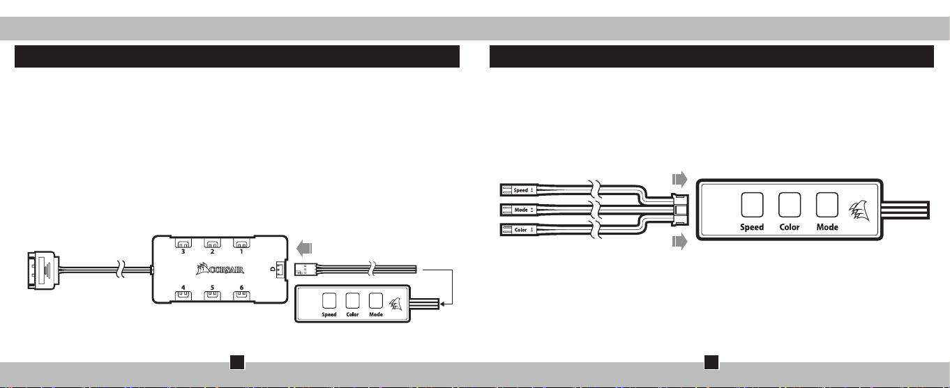
> Find a location for the RGB LED controller that allows the cable to reach
the fan hub and gives you easy access to the buttons.
> Mount the RGB LED controller with the provided mounting strip.
> Plug in the 3 pin cable from the fan controller into the fan hub.
> Plug in the SATA power cable from the fan hub into an unused
SATA power connector from the system PSU.
> Plug the fan power cable into an unused fan port on your MB or fan controller.
• The fan power cable provides power.
• The RGB LED cable provides power and control for the RGB LED’s.
> Both cables are required to be plugged into their
respective ports in order for proper operation of the fan.
SP120 RGB FANSP120 RGB FAN
Optional InstallationInstallation Continued
> An optional cable is supplied that allows connection to a pushbutton
to operate the mode, color, and speed options from an external source.
> Chassis buttons such as reset pushbutton or power pushbutton
are examples of pushbutton that would work with the optional cable.
> Connect the optional cable to the port on the top of the controller
(the connector next to the “SP RGB Controller” on the fan controller.)
5
6
Page 7

Table des matières
SP120 RGB FAN
Introduction: ............................................................................................................................................
ContenudukitSPRGB: .......................................................................................................................
Installation: ............................................................................................................................................
Suitedel’installation:........................................................................................................................
Installationfacultative: .....................................................................................................................
7
Congratulations
La gamme de ventilateurs SP RGB de CORSAIR combine hautes performances et
éclairage LED RGB.
Caractéristiques du kit SP RGB
Ventilateurs 3
Kit 3
Ventilateurs
Kit 1
Ventilateur
1 Ventilateur
Hub de ventilation 1
Contrôleur de ventilation 1
Vis de montage 12
Bandes de fixation 2
Ventilateurs 1
Hub de ventilation 1
Contrôleur de ventilation 1
Vis de montage 4
Bandes de fixation 2
Ventilateurs 1
Vis de montage 4
8
Page 8
COLOR
Blanc Rouge Orange Jaune Vert Bleu Violet B>R>O>J>V>B>V
> Sélection des couleurs – Blanc > Rouge > Orange > Jaune > Vert >
Bleu > Violet > Défilement de toutes les couleurs > retour au début.
MODE
Pulsations et lumière vacillante
Statique
Pulsation Vacillante
> Sélection du mode – Pulsations et lumière vacillante > Statique >
Pulsations > Lumière vacillante > Retour au début.
SPEED
Rapide Moyenne Lente
> Sélection de la vitesse – Rapide > Moyenne > Lente > Retour au début.
1. Une fois que tous les éléments sont bien connectés et mis sous tension, appuyez une
fois sur le bouton de l’option qui vous intéresse et que vous souhaitez modifier afin
d’avancer dans le cycle de sélection.
2. Les boutons sont directement achés
sur le contrôleur de ventilation.
a. Color = sélection de la couleur
b. Mode = sélection du mode
c. Speed = sélection de la vitesse
SP120 RGB FANSP120 RGB FAN
InstallationSP RGB Series Features
> Remarques sur la connectique
• Les câbles des LED du ventilateur doivent
être connectés au hub de ventilation en
respectant l’ordre des eets lumineux voulus.
• Les ventilateurs doivent commencer à la
position « 1 » et continuer en série.
1 > 2 > 3 > 4 > 5 > 6
• Un ventilateur non connecté en série
entraînera l’arrêt de la communication et de
la fonction d’éclairage LED RGB.
> Montez les ventilateurs à l’emplacement de
votre choix dans le châssis.
> Trouvez pour le hub de ventilation un
emplacement susamment spacieux pour
connecter tous les câbles des LED RGB des
ventilateurs installés dans votre système.
• Le contrôleur de ventilation devra également
être branché au hub de ventilation pour
pouvoir contrôler l’éclairage LED RGB.
> Installez le hub de ventilation à l’aide des
bandes de fixation fournies.
9
10
Page 9

> Trouvez un emplacement pour le contrôleur RGB LED. Il doit être susamment
spacieux pour que le câble atteigne le hub de ventilation et pour que vous ayez un
accès facile aux boutons.
> Installez le contrôleur LED RGB à l’aide de la bande de fixation fournie.
> Branchez le câble à 3 broches du contrôleur de ventilation au hub de ventilation.
> Branchez le câble d’alimentation SATA du hub de ventilation à un connecteur
d’alimentation SATA libre sur l’alimentation système.
> Branchez le câble d’alimentation du ventilateur sur un port de ventilation
libre de votre carte mère ou du contrôleur de ventilation.
• Le câble d’alimentation du ventilateur alimente le contrôleur en électricité.
• Le câble LED RGB fournit de l’alimentation et permet le contrôle des LED RGB.
> Les deux câbles doivent être branchés sur leur port respectif pour
que le ventilateur puisse fonctionner correctement.
SP120 RGB FANSP120 RGB FAN
Installation facultativeSuite de l’installation
> Un câble facultatif est fourni pour permettre une connexion à un commutateur en vue
de contrôler le mode, la couleur et la vitesse à partir d’une source externe.
> Les boutons du châssis comme les boutons de réinitialisation ou d’alimentation sont
des exemples de boutons poussoirs qui pourraient fonctionner avec le câble facultatif.
> Connectez le câble en option au port situé sur le dessus du contrôleur
(le connecteur situé à côté du texte « SP RGB Controller »,
sur le contrôleur de ventilation).
11
12
Page 10

Sommario
SP120 RGB FAN
Introduzione: .........................................................................................................................................
CaratteristichedelleventoleSPRGB: ........................................................................................
Installazione: .........................................................................................................................................
Installazionecontinua: ......................................................................................................................
Installazioneopzionale: ...................................................................................................................
13
Introduzione
La serie CORSAIR SP RGB di ventole riunisce in un’unica confezione prestazioni elevate
e illuminazione RGB LED.
Contenuto del kit SP RGB
Ventole 3
Kit da tre
ventole
Kit a ventola
singola
Ventola singola
Hub per ventole 1
Controller per ventole 1
Viti di montaggio 12
Strisce di montaggio 2
Ventole 1
Hub per ventole 1
Controller per ventole 1
Viti di montaggio 4
Strisce di montaggio 2
Ventole 1
Viti di montaggio 4
14
Page 11

COLOR
Bianco Rosso Arancione Giallo Verde Azzurro Viola B>R>A>G>V>A>V
> Selezione colore – Bianco > Rosso > Arancione > Giallo > Verde > Azzurro > Viola >
Scorrimento tra tutti i colori > Ritorno all’inizio.
MODE
StaticBreathing & Flicker Breathing Flicker
> Selezione modalità – Breathing & Flicker > Static > Breathing >
Flicker > Ritorno all’inizio.
SPEED
Rapida Media Lenta
> Selezione velocità – Rapida > Media > Lenta > Ritorno all’inizio.
1. Una volta che tutti gli elementi sono stati collegati e alimentati correttamente, ti
basta premere il pulsante sull’opzione corrispondente da modificare per spostarti
avanti di una posizione nel ciclo di selezione.
2. I pulsanti sono etichettati sul controller per ventole.
a. Colore = Selezione colore
b. Modalità = Selezione modalità
c. Velocità = Selezione velocità
SP120 RGB FANSP120 RGB FAN
InstallazioneCaratteristiche della serie SP RGB
> Note di cablaggio
• Il cablaggio dei LED delle ventole va
eettuato con l’apposito hub al fine di
visualizzare gli eetti luminosi.
• Le ventole devono iniziare dal n. “1” e
continuare in serie. 1 > 2 > 3 > 4 > 5 > 6
• Un’eventuale ventola non collegata in serie
interromperà la comunicazione impedendo il
funzionamento dell’illuminazione a LED RGB.
> Monta le ventole nella posizione
preferita all’interno del telaio.
> Trova una posizione per l’hub per ventole che
consenta il collegamento di tutti i cavi LED
RGB delle ventole installati nel sistema.
• Il controller delle ventole dovrà anch’esso
essere collegato all’hub per ventole per il
controllo dell’illuminazione LED RGB.
> Monta l’hub per ventole con le fasce di
montaggio fornite.
15
16
Page 12

> Trova una posizione per il controller LED RGB che consenta al cavo di
raggiungere l’hub per ventole e di fornirti un semplice accesso ai pulsanti.
> Monta il controller LED RGB utilizzando la fascia di montaggio fornita.
> Inserisci il cavo a 3 pin dal controller all’hub per ventole.
> Inserisci il cavo di alimentazione SATA dall’hub per ventole in un connettore di
alimentazione SATA inutilizzato collegato all’alimentatore del sistema.
> Inserisci il cavo di alimentazione per ventole in una porta per ventole
inutilizzata sulla tua scheda madre o sul controller delle ventole.
• Il cavo di alimentazione per ventole fornisce alimentazione.
• Il cavo LED RGB fornisce alimentazione e controllo per i LED RGB.
> Entrambi i cavi devono essere inseriti nelle rispettive porte ai fini del corretto
funzionamento della ventola.
SP120 RGB FANSP120 RGB FAN
Installazione opzionaleInstallazione continua
> Viene fornito un cavo opzionale che consente la connessione a uno switch
per gestire le opzioni di modalità, colore e velocità da una fonte esterna.
> I pulsanti del telaio come gli switch di reset o i pulsanti di
alimentazione sono esempi di switch azionabili con il cavo opzionale.
> Collega il cavo opzionale alla porta posta in cima al controller
(il connettore accanto al “Controller RGB SP” sul controller per ventole.
17
18
Page 13

Inhaltsverzeichnis
SP120 RGB FAN
Einführung: ............................................................................................................................................
SPRGBSeriesFeatures: ..................................................................................................................
Installation: ............................................................................................................................................
InstallationFortsetzung: ................................................................................................................
OptionaleInstallation: ......................................................................................................................
19
Einführung
Die Lüfter der CORSAIR SP RGB Series bieten eine hohe Leistung und eine
ansprechende RGB-LED-Beleuchtung
SP RGB Kit-Komponenten
Lüfter 3
Lüfternabe 1
Drei-Lüfter-Kit
Ein-Lüfter-Kit
Einzelner Lüfter
Lüftersteuerung 1
Montageschrauben 12
Montageleisten 2
Lüfter 1
Lüfternabe 1
Lüftersteuerung 1
Montageschrauben 4
Montageleisten 2
Lüfter 1
Montageschrauben 4
20
Page 14

COLOR
Weiß Rot
Orange
Gelb Grün Blau Violett
W>R>O>G>G>B>V
> Farbauswahl – Weiß > Rot > Orange > Gelb > Grün > Blau >
Violett > Durch alle Farben blättern > Zurück zum Anfang.
MODE
StatischPulsen und Flimmern Pulsen Flimmern
> Modusauswahl – Pulsen und Flimmern > Statisch > Pulsen >
Flimmern > Zurück zum Anfang.
SPEED
Schnell Mittel Langsam
> Geschwindigkeitsauswahl – Schnell -> Mittel -> Langsam -> Zurück zum Anfang.
1. Wenn alle Elemente ordnungsgemäß angeschlossen und eingeschaltet wurden,
drücken Sie einmal die Taste für die Option, die Sie ändern möchten, um mit dem
Auswahlprozess fortzufahren.
2. Die Tasten sind auf der Lüftersteuerung beschriftet.
a. Farbe = Farbauswahl
b. Modus = Modusauswahl
c. Geschwindigkeit = Geschwindigkeitsauswahl
SP120 RGB FANSP120 RGB FAN
InstallationFunktionen der SP RGB-Serie
> Anschlusshinweise
• Die LED-Kabel des Lüfters müssen
in der Reihenfolge an die Lüfternabe
angeschlossen werden, in der die
Lichteekte angezeigt werden sollen.
• Die Lüfter müssen bei „1“ beginnen und
in numerischer Reihenfolge angeordnet
werden. 1 -> 2 -> 3 -> 4 -> 5 -> 6
• Jeder Lüfter, der nicht in der richtigen
Reihenfolge angeschlossen ist,
unterbricht die Kommunikation und
damit das Funktionieren der RGB LEDBeleuchtungsfunktion.
> Montieren Sie den/die Lüfter an der gewünschten Stelle im Gehäuse.
> Suchen Sie einen geeigneten Ort für die Lüfternabe, an dem Sie alle
RGB LED-Kabel der in Ihrem System installierten Lüfter so anschließen
können, dass sie gut zugänglich sind.
• Die Lüftersteuerung muss zur Steuerung der RGB LED-Beleuchtung
ebenfalls an der Lüfternabe angeschlossen werden.
> Montieren Sie die Lüfternabe mithilfe der mitgelieferten Montageleisten.
21
22
Page 15

> Finden Sie eine Position für die RGB-LED-Steuerung, von der aus die Kabel
zur Lüfternabe geführt werden können und an der Sie einfachen Zugang zu
den Tasten haben.
> Montieren Sie die RGB LED-Steuerung mithilfe der mitgelieferten Montageleiste.
> Verbinden Sie das dreipolige Kabel von der Lüftersteuerung mit der Lüfternabe.
> Stecken Sie das SATA-Netzkabel der Lüfternabe in einen ungenutzten
SATA-Steckplatz des System-Netzteils.
> Stecken Sie das Lüfter-Netzkabel in einen ungenutzten Lüfter-Anschluss
an Ihrem MB oder an der Lüftersteuerung.
• Das Lüfter-Netzkabel liefert Strom.
• Das RGB LED-Kabel liefert Strom und ermöglicht die Steuerung der RGB LEDs.
> Beide Kabel müssen für den einwandfreien Betrieb des Lüfters in die jeweils
vorgesehenen Anschlüsse gesteckt werden.
SP120 RGB FANSP120 RGB FAN
Optionale InstallationInstallation, Fortsetzung
> Ein optionales Kabel wird mitgeliefert, das die Verbindung mit einem Schalter zum
Umschalten zwischen Modus-, Farb- und Geschwindigkeitsoptionen von einer
externen Quelle aus ermöglicht.
> Gehäuseschalter, wie z. B. der Rücksetzschalter oder die Ein/Austaste,
sind Beispiele für Schalter, die mit dem optionalen Kabel funktionieren.
> Verbinden Sie das optionale Kabel mit dem Anschluss auf der Oberseite der
Steuerung (dem Anschluss neben der „SP-RGB-Steuerung“ auf der Lüftersteuerung).
23
24
Page 16

Índice
SP120 RGB FAN
Introducción: .........................................................................................................................................
CaracterísticasdeSPRGB: .............................................................................................................
Instalación: .............................................................................................................................................
Instalación(continuación): .............................................................................................................
Instalaciónopcional: .........................................................................................................................
25
Introducción
La serie de ventiladores CORSAIR SP RGB ofrece un alto rendimiento e
iluminación LED RGB en un solo paquete.
Contenidos del Kit SP RGB
Ventiladores 3
Kit de tres
ventiladores
Kit de
ventilador único
Ventilador único
Plataforma de ventilador 1
Controlador de ventilador 1
Tornillos de montaje 12
Bandas de fijación 2
Ventiladores 1
Plataforma de ventilador 1
Controlador de ventilador 1
Tornillos de montaje 4
Bandas de fijación 2
Ventiladores 1
Tornillos de montaje 4
26
Page 17

COLOR
Blanco Rojo Naranja Amarillo Verde Azul Violeta
B>R>N>A>V>A>V
> Selección de colores – Blanco > Rojo > Naranja > Amarillo > Verde > Azul > Violeta >
Desplazarse por todos los colores > volver al principio
MODE
EstáticoRespiración & Iluminación activa Respiración Iluminación activa
> Selección de modos – Respiración & Iluminación activa > Estático
> Respiración > Iluminación activa > Volver al inicio.
SPEED
Rápido Medio Lento
> Selección de velocidades – Rápido > Medio > Lento > Volver al principio
1. Cuando todos los elementos estén conectados adecuadamente y encendido, pulse el
botón de la opción correspondiente que le gustaría cambiar para avanzar en el ciclo
de selección.
2. Los botones están marcados en el
propio controlador del ventilador.
a. Color = Selección del color
b. Mode = Selección del modo
c. Speed = Selección de la velocidad
SP120 RGB FANSP120 RGB FAN
InstalaciónCaracterísticas de SP RGB Series
> Indicaciones de conexión
• El cableado del ventilador LED debe
conectarse a la plataforma del ventilador
para poder mostrar los efectos de
iluminación.
• Los ventiladores deben empezar en «1» y
continuar en serie. 1 > 2 > 3 > 4 > 5 > 6
• Si un ventilador no está conectado en serie,
se romperá la comunicación y la función de
iluminación RGB LED no funcionará.
> Monte el/los ventilador/es donde
desee en el chasis.
> Busque un lugar donde la plataforma del
ventilador pueda conectarse a todos los
cables del RGB LED de los ventiladores
instalados en su sistema.
• El controlador del ventilador también debe
enchufarse a la plataforma del ventilador
para controlar la iluminación RGB LED.
> Monte la plataforma del ventilador con las
bandas de fijación proporcionadas.
27
28
Page 18

> Busque un lugar para el controlador LED RGB que permita al cable alcanzar la
plataforma del ventilador y donde pueda acceder fácilmente a los botones.
> Monte el controlador del RGB LED con la banda de fijación proporcionada.
> Conecte el cable de 3 pines del controlador del ventilador a la plataforma del ventilador.
> Conecte el cable de alimentación SATA de la plataforma
del ventilador a un conector SATA sin utilizar desde su sistema PSU.
> Conecte el cable de alimentación del ventilador a un puerto para
ventiladores sin utilizar en su MB o controlador de ventiladores.
• El cable de alimentación del ventilador le suministra energía.
• El cable del RGB LED le suministra energía y control al RGB LED.
> Ambos cables deben estar conectados a sus puertos
respectivos para el correcto funcionamiento del ventilador.
SP120 RGB FANSP120 RGB FAN
Instalación OpcionalInstalación (continuación)
> Se proporciona un cable opcional que permite la conexión a un enchufe para operar
las opciones de modo, color y velocidad desde una fuente externa.
> Los botones del chasis, así como el de reinicio o
encendido, son ejemplos de funciones del cable opcional.
> Conecte el cable opcional al puerto de la parte superior del controlador
(el conector que está al lado del “SP RGB Controller” del controlador del ventilador).
29
30
Page 19

Оглавление
SP120 RGB FAN
Введение: .................................................................................................................................................
Характеристики SP RGB: ......................................................................................................................
Установка: ................................................................................................................................................
Установка (продолжение): ..................................................................................................................
Альтернативная установка: ................................................................................................................
31
Введение
Серия вентиляторов CORSAIR SP RGB: высокая производительность и светодиодная
RGB-подсветка в одном устройстве
Содержимое комплекта SP RGB
вентилятора
Комплект из трех
вентиляторов
Комплект из одного
вентилятора
Вентилятор
разветвитель питания вентилятора
контроллер вентиляторов
крепежных винтов
монтажных планки
вентилятора
разветвитель питания вентилятора
контроллер вентиляторов
крепежных винтов
монтажных планки
вентилятора
крепежных винтов
32
3
1
1
12
2
1
1
1
4
2
1
4
Page 20

SP120 RGB FANSP120 RGB FAN
Характеристики вентиляторов SP RGB Series
COLOR
Белый Красный Оранжевый Желтый Зеленый Синий Фиолетовый
> Выбор цвета – Белый > Красный > Оранжевый > Желтый > Зеленый > Синий > Фиолетовый >
Циклическое переключение цветов > Возврат в начало.
MODE
СтатическийПульсация и мерцание Пульсация Мигание
> Выбор режима – Пульсация и мерцание > Статичный > Пульсация >
Мерцание > Возврат в начало.
SPEED
Высокая Средняя Низкая
> Выбор скорости – Высокая > Средняя > Низкая > Возврат в начало.
1. Когда все элементы соединены надлежащим образом и подключены к сети, просто нажмите
кнопку опции, которую хотите изменить, чтобы перейти к циклу выбора.
2. Кнопки обозначены непосредственно
на контроллере вентилятора.
a. Color (Цвет) = Выбор цвета
b. Mode (Режим) = Выбор режима
c. Speed (Скорость) = Выбор скорости
33
W>R>O>Y>G>B>V
Установка
> Примечания по подключению
• Для того чтобы отобразить эффекты подсветки,
провода светодиодной подсветки вентилятора
подключают к разветвителю питания вентилятора.
• Вентиляторы должны запускаться
последовательно, начиная с первого.
1 > 2 > 3 > 4 > 5 > 6
• Если один из вентиляторов не подключен
последовательно, произойдет размыкание
соединения и функция светодиодной подсветки
RGB работать не будет.
> Вентиляторы устанавливают внутри
корпуса в выбранном месте.
> Место для установки разветвителя питания вентилятора
выбирается таким образом, чтобы длины кабелей
светодиодной подсветки RGB всех вентиляторов системы
хватило для подключения к соответствующим разъемам.
• Для управления светодиодной подсветкой RGB
контроллер вентиляторов также необходимо подключить к
разветвителю питания вентилятора.
> Прикрепите разветвитель питания вентилятора с помощью
монтажных планок из комплекта.
34
Page 21

> Расположите контроллер RGB-светодиодов таким образом, чтобы свободно
подвести кабель к разветвителю питания и обеспечить удобный доступ к кнопкам.
> Прикрепите контроллер светодиодной подсветки RGB с помощью монтажной планки из комплекта.
> Подключите кабель с тремя контактами, идущий от контроллера вентилятора, к разветвителю питания.
> Подключите кабель питания SATA, идущий от разветвителя питания вентилятора,
к свободному разъему питания SATA на блоке питания системы.
> Подключите кабель питания вентилятора к свободному разъему вентилятора
на материнской плате или на контроллере вентилятора.
• По кабелю питания вентилятора подается электропитание.
• По кабелю светодиодной подсветки RGB подается электропитание
и осуществляется управление RGB-светодиодами.
> Для правильной работы вентилятора оба кабеля
необходимо подключить к соответствующим разъемам.
SP120 RGB FANSP120 RGB FAN
Альтернативная установкаУстановка (продолжение)
> В комплекте поставки имеется дополнительный кабель для подключения к переключателю, с
помощью которого от внешнего источника осуществляется управление режимами, настройками
цвета и скоростью работы.
> В качестве примера переключателей, которые рассчитаны на работу от
внешнего источника, служат кнопки перезапуска или кнопки питания на корпусе.
> Подключите дополнительный кабель к разъему в верхней части контроллера
(разъем, следующий за разъемом SP RGB Controller («Контроллер SP RGB»)
на контроллере вентилятора).
35
36
Page 22

Índice
SP120 RGB FAN
Introdução: ............................................................................................................................................
RecursosSPRGB: ...............................................................................................................................
Instalação: ..............................................................................................................................................
Continuaçãodainstalação: ............................................................................................................
Instalaçãoopcional: ...........................................................................................................................
37
Introdução
A série de ventoinhas CORSAIR SP RGB oferece-lhe elevado desempenho
e iluminação por LED RGB em um só produto
Kit de acessórios SP RGB
Ventoinha 3
Três kits de
ventoinhas
Um único kit de
ventoinha
Uma única
ventoinha
Hub 1
Controlador 1
Parafusos de montagem 12
Fitas de montagem 2
Ventoinha 1
Hub 1
Controlador 1
Parafusos de montagem 4
Fitas de montagem 2
Ventoinha 1
Parafusos de montagem 4
38
Page 23

COLOR
Branco Vermelh Laranja Amarelo Verde Azul Violeta
B>V>L>A>V>A>V
> Seleção de cor – Branco > Vermelh > Laranja > Amarelo > Verde > Azul > Violeta >
Percorrer todas as cores > regressar ao início.
MODE
EstáticoPulsação e tremulação Pulsação Tremulação
> Seleção de modo – Pulsação e tremulação > Estático > Pulsação >
Tremulação > Regressar ao início.
SPEED
Rápido Médio Lento
> Seleção de velocidade – Rápido > Médio > Lento > Regressar ao início
1. Assim que todos os itens estiverem devidamente ligados e conectados, pressione
uma vez o botão da opção correspondente que gostaria de alterar para avançar no
ciclo de seleção.
2. Os botões estão etiquetados no
próprio controlador da ventoinha.
a. Cor = Seleção da cor
b. Modo = Seleção do modo
c. Velocidade = Seleção da velocidade
SP120 RGB FANSP120 RGB FAN
InstalaçãoRecursos da série SP RGB
> Notas de ligação
• A fiação do LED da ventoinha deve estar
conectada ao hub na ordem pretendida
para a exibição dos efeitos de luz.
• As ventoinhas devem começar em “1” e
continuar em série. 1 > 2 > 3 > 4 > 5 > 6
• Qualquer ventoinha que não esteja
ligada em série quebrará a comunicação
e a função de iluminação LED RGB não
funcionará.
> Instale a(s) ventoinha(s) no local
desejado no chassi.
> Procure um local para o hub que permita
a conexão de todos os cabos LED RGB das
ventoinhas instalados em seu sistema.
• Também é necessário conectar o
controlador da ventoinha ao hub
para controlar a iluminação LED RGB.
> Monte o hub com as fitas de montagem fornecidas.
39
40
Page 24

> Procure um local para o controlador RGB LED que permita que o cabo alcance o hub
da ventoinha sem problemas e lhe permita acessar facilmente os botões.
> Monte o controlador LED RGB com a fita de montagem fornecida.
> Conecte o cabo de 3 pinos do controlador ao hub da ventoinha.
> Conecte o cabo de alimentação SATA do hub a um conector
de alimentação SATA livre da PSU do sistema.
> Conecte o cabo de alimentação da ventoinha a uma porta
livre na motherboard ou no controlador da ventoinha.
• O cabo de alimentação da ventoinha fornece energia.
• O cabo LED RGB fornece energia e controle aos LEDs RGB.
> É necessário conectar ambos os cabos em suas respetivas
portas para um funcionamento correto da ventoinha.
SP120 RGB FANSP120 RGB FAN
Instalação OpcionalContinuação da Instalação
> Junto encontrará um cabo opcional que permite a conexão a um interruptor para
controlar as opções de modo, cor e velocidade a partir de uma fonte externa.
> Os botões do chassi, tais como os interruptores de redefinição, são
exemplos de interruptores que funcionariam com o cabo opcional.
> Conecte o cabo opcional à porta no cimo do controlador
(o conector junto do “Controlador SP RGB” no controlador da ventoinha).
41
42
Page 25

目录
SP120 RGB FAN
简介: ...........................................................................................................................................................
SPRGB功能: ..........................................................................................................................................
安装: ...........................................................................................................................................................
安装(接续): ...............................................................................................................................................
可选安装: ...................................................................................................................................................
43
简介
CORSAIR SP RGB 系列风扇在一个包中不单提供高性能而且具有 RGB LED 照明。
SP RGB 配套件内容
风扇
风扇集线器
三个风扇配套
单个风扇配套
单个风扇
风扇控制器
安装螺丝
安装条
风扇
风扇集线器
风扇控制器
安装螺丝
安装条
风扇
安装螺丝
44
3
1
1
12
2
1
1
1
4
2
1
4
Page 26

SP120 RGB FANSP120 RGB FAN
SP RGB 系列特点
COLOR
白色 红色 橙色 黄色 绿色 蓝色 蓝紫色
> 颜色选择 – 白色 > 红色 > 橙色 > 黄色 > 绿色 > 蓝色 > 蓝紫色 >
在所有颜色间循环轮换 > 返回开始处.
MODE
静态微风和摆动 微风 摆动
> 模式选择 – 微风和摆动 > 静态 > 微风 > 摆动 > 返回开始处.
SPEED
快 中 慢
> 速度选择 – 快 > 中 > 慢 > 返回开始处.
1. 所有项目连接妥当后,开启电源,按一下要更改的相应选项的按钮,可在循环选择中轮换。
2. 风扇控制器上按钮均有标签标示。
a. 颜色 = 颜色选择
b. 模式 = 模式选择
c. 速度 = 速度选择
45
白
>红>橙>黄>绿>蓝>紫
安装
> 连接注意事项
• 风扇 LED 布线必须以您要显示的照明效果的顺序
连接到风扇集线器。
• 风扇必须从 “1” 开始并依序连续运转。
1 > 2 > 3 > 4 > 5 > 6
• 未依序连接的风扇会中断通信,而 RGB LED
照明功能将无法作用。
> 将风扇安装到您在机箱中选择的位置。
> 找出一个可让风扇集线器连接安装在系统中的所有
风扇 RGB LED 电缆且容易触及的位置。
• 风扇控制器也需要插入风扇集线器,
以控制 RGB LED 照明。
> 使用随附的安装条安装风扇集线器。
46
Page 27

SP120 RGB FANSP120 RGB FAN
安装(接续)
> 为 RGB LED 控制器找出一个位置,使得电缆能接到风扇集线器,并让您容易使用按钮。
> 使用随附的安装条安装 RGB LED 控制器。
> 将风扇控制器的 3 针电缆插入风扇集线器。
> 将风扇集线器的 S ATA 电源线接到系统 PSU 中未使用的 SATA 电源接头。
> 将风扇电源线接到 MB 或风扇控制器上未使用的风扇端口。
• 风扇电源线提供电源。
• RGB LED 电源线提供电源并控制 RGB LED。
> 两边电缆都需要接到各自的端口,才能让风扇正常运转。
47
可选安装
> 提供可选电缆,可用于连接到开关来操作外部来源的模式、色彩和速度选项。
> 例如重置开关的机箱按钮或电源按钮都是开关示例,可搭配可选电缆使用。
> 将选配电缆连接到控制器顶部的端口 (风扇控制器上“SP RGB 控制器”旁的控制器)。
48
Page 28

目次
SP120 RGB FAN
はじめに: ...................................................................................................................................................
SPRGB機能: ..........................................................................................................................................
取り付け: ...................................................................................................................................................
取り付け(続き): .......................................................................................................................................
オプションの取り付け: ..........................................................................................................................
49
はじめに
CORSAIR SP RGB ファンシリーズは、ひとつのパッケージで高性能と RGB LED ライトを提供
します。
SP RGB キット同梱物
3 個の
ファンキット
1 個の
ファンキット
1 個のファン
ファン
ファンハブ
ファンコントローラ
取り付け用ねじ
取り付け用ストリップ
ファン
ファンハブ
ファンコントローラ
取り付け用ねじ
取り付け用ストリップ
ファン
取り付け用ねじ
50
3
1
1
12
2
1
1
1
4
2
1
4
Page 29

SP120 RGB FANSP120 RGB FAN
SP RGB シリーズ機能
COLOR
白 赤 オレンジ 黄 緑 青 紫
> 色の選択 – 白 > 赤 > オレンジ > 黄 > 緑 > 青 > 紫 >
すべての色を循環します > 最初に戻ります。
MODE
静止ブリージング & フリッカー 呼吸 フリッカー
> モードの選択 – ブリージング & フリッカー > 静止 >
ブリージング > フリッカー > 最初に戻る。
SPEED
速い 標準 遅い
> 速度の選択 – 速い > 標準 > 遅い > 最初に戻る。
1. すべてのアイテムが適切につながって電源が入ったら、変更したい対応するオプションのボタ
ンを押して選択したサイクルで進めます。
2. ファン コントローラにボタンの
ラベルが貼ってあります。
a. 色 = カラー選択
b. モード = モード選択
c. 速度 = 速度選択
51
白
>赤>橙>黄>緑>青>紫
取り付け
> 接続についての注記
• ファンの LED 配線は、表示するライティング
効果の順番でファンハブにつなげる
必要があります。
• ファンは「1」から開始して順番に継続しなけれ
ばなりません。 1 > 2 > 3 > 4 > 5 > 6
• 順番でつながっていないファンは通信が
中断し、RGB LED ライティング
機能は稼働しません。
> ファンをシャーシの希望する
場所に取り付けます。
> システムに設置したすべてのファン RGB LED ケ
ーブルと接続できる、ファンハブの場所を見つけ
てください。
• また RGB LED ライティングを制御するため
に、ファンコントローラをファンハブに接続す
る必要があります。
> 同梱されている取り付け用ストリップでファンハ
ブを取り付けます。
52
Page 30

SP120 RGB FANSP120 RGB FAN
取り付け(続き)
> ケーブルがファン ハブに届き、ボタンに容易にアクセスできる、RGB コントローラの場所を
見つけてください。
> 同梱されている取り付け用ストリップで RGB LED コントローラを取り付けます。
> ファン コントローラの 3 ピン ケーブルをファン ハブに差し込みます。
> ファンハブからの SATA パワーケーブルをシステム電源の使用されていない
SATA パワーコネクタに差し込みます。
> ファン パワー ケーブルをマザーボードまたはファンコントローラの
使用されていないファンポートに差し込みます。
• ファン パワー ケーブルはファンへの電源と PWM 制御を供給します。
• RGB LED ケーブルは、RGB LED への電源と制御を供給します。
> ファンを動作させるには、両方のケーブルをそれぞれのポートに差し込む必要があります。
53
オプションの取り付け
> 外部ソースから、モード、色、速度のオプションを切り替えるスイッチへ
接続できるオプションのケーブルが同梱されています。
> 例を挙げると、リセットスイッチや電源ボタンなどのシャーシボタンが、
このオプションのケーブルで機能するスイッチです。
> オプティカル ケーブルをコントローラ上部のポートにつなげます
(ファン コントローラの「SP RGB コントローラ」の隣にあるコネクタ)。
54
 Loading...