

Page 1
T2 ES/ T4 ES
TURBINES
USER MANUAL
Page 2

Page 3

© Corroventa Ltd.
2017.02
1 (25)
Table of Contents
Intended use .............................................................................................................................................. 2
Manufacturing Directive ............................................................................................................................ 3
Safety information .................................................................................................................................... 4
Relative humidity and its effect on substances ...................................................................................... 5
How to select dryer type............................................................................................................................ 5
Delivery inspection ..................................................................................................................................... 6
Product Overview ....................................................................................................................................... 6
Drying methods.......................................................................................................................................... 7
Suction drying ........................................................................................................................................ 7
Pressure drying ...................................................................................................................................... 7
Installation ................................................................................................................................................. 8
Accessories and consumables .................................................................................................................. 9
To Use CTR T ES, menus and operation ................................................................................................... 9
Network functions .................................................................................................................................... 15
How to network machines ...................................................................................................................... 16
Alarms ....................................................................................................................................................... 17
Service Reminder ...................................................................................................................................... 17
Maintenance and service ......................................................................................................................... 18
Fault finding ................................................................................................................................................. 19
Technical data .............................................................................................................................................. 20
Interface Map for CTR A2ES, CTR A4 ES and CTR A ES ............................................................................. 21
Page 4
© Corroventa Ltd.
2017.02
2 (25)
• High Capacity
• Low weight – easy to carry and install
•
•
•
•
• Very low noise
• Energy and time meter – resettable work counter
User Manual CTR T ES
Intended use
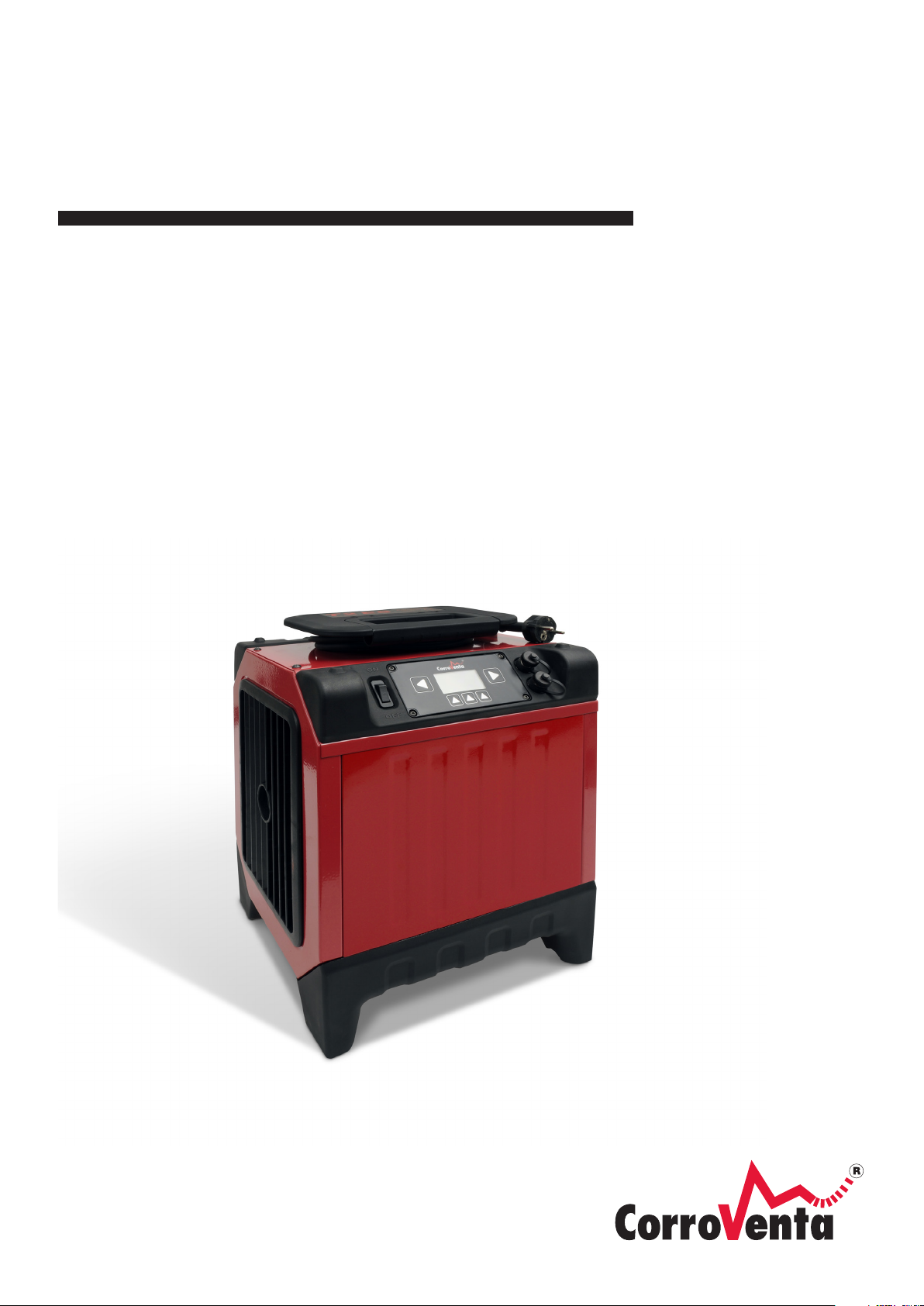
The CTR T ES, including the CTR T2 ES and the larger CTR T4 ES, is the first digital turbine family
developed and intended for construction drying and water damage restoration where the machines
are used for suction and pressure drying in combination with adsorption dryers.
Through its control panel, the CTR T ES provides the user with the ability to set desired air flow,
resettable energy and time counter as well as timer operation. Part of the new CTR ES family, the
CTR T ES is also capable of networked operation and it is prepared for remote monitoring and control.
The unit has cable parking integrated with its foldable carrying handle and its low weight makes it
easy to carry and install. Durable yet flexible feet protect floor surfaces while also allowing stacking
of machines. The turbine is naturally as robust in its design as its predecessors, a prerequisite for a
long service life. Thanks to the very low noise, it can be used for both construction drying and water
damage restoration without the occupants having to evacuate.
Features:
Energy efficient
Robust
Digital interface with networking capabilities
Variable speed and flow control
Page 5

© Corroventa Ltd.
2017.02
3 (25)
Manufacturing Directive
CTR T2 ES and the CTR T4 ES are CE approved.
Waiver of Liability
• Faulty, incorrect installations and/or incorrect use can cause damage to property and human
injury.
• The manufacturer assumes no responsibility or liability for damages or injuries caused by
non-compliance with the instructions herein, use for other purposes than the intended, or
failure to observe its warnings. Such damage, injuries or liabilities are not covered by the
product warranty.
• The product warranty does not cover consumables or normal wear and tear.
• It is the responsibility of the buyer to inspect the product at time of delivery and before use
to ensure its good function. The product warranty does not cover damage resulting from use
of faulty products.
• Changes or modifications to the equipment must not be made without written consent by
Corroventa Avfuktning AB.
• The product, technical data and/or installation and operation instructions can be changed
without prior notice.
• This manual contains information that is protected by the Intellectual Property laws. No part
of this manual may be copied, stored in an information system or transferred in any form or
in any way without the written consent of Corroventa Avfuktning AB.
Any comments on the contents of this document shall be sent or addressed to:
Corroventa Avfuktning AB Tel +46(0)36-37 12 00
Mekanikervägen 3 Fax +46(0)36-37 18 30
564 35 Bankeryd, SWEDEN E-post [email protected]
Page 6

© Corroventa Ltd.
2017.02
4 (25)
Safety information
This equipment can be used by children aged eight (8) years or above and people with reduced
physical, sensory or mental capabilities or with lack of experience and knowledge provided they have
been given instructions and information on how it is safely used and that they understand the
hazards involved. Children must not be allowed to play with the equipment. Cleaning and
maintenance must not be performed by children without supervision.
Electrical installations made in connection with the installation of the turbine shall be made by
authorized personnel in accordance with local and national regulations.
Furthermore, the following warnings and instructions shall be read and observed:
1. The turbine is intended for indoor use only.
2. The turbine must not be powered until the installation is finished in accordance with this
manual.
3. The powered turbine must not be covered as this can lead to overheating and fire hazard.
4. The turbine must not be used as table, trestle, pallet or stool.
5. The turbine must not be used to step or stand on.
6. Never use the turbine without the filter installed as this can cause damage to it. Ensure that
the filter is clean. A cluttered filter can cause the turbine to overheat.
7. Oil, fat, solvents, boracol or similar substances must not be drawn into the turbine.
8. The turbine must not be used in spaces where explosive gases can be present.
9. Do not stick objects into the air outlets or intakes as this can cause damage to the machinery
as well as human injury.
10. Install the turbine steadily and leveled so that it cannot fall over.
11. Keep children, animals and spectators away from the work place while installation is
undertaken.
12. If the turbine is broken, if the power connector or the cable is damaged, contact the retailer.
Do not repair the equipment if you have not received specific training by the manufacturer.
13. Be careful not to damage the power cable. The cable must not go through water or pass
sharp edges.
14. Never carry or tow the turbine by its cable.
15. To use electrical equipment in humid or wet environment can be dangerous. Never power the
turbine if it is standing in water.
16. The dryer must only be connected to grounded power outlet with voltage and frequency in
accordance with turbine nameplate.
17. A residual-current device / ground fault circuit interrupter should be used to minimize the
risk of electric shocks.
18. Water must not come in contact with the electrical components of the equipment. If this has
happened, ensure that the equipment is dry before it is used again.
19. The power must always be disconnected before the turbine is opened.
20. Air hoses/pipes that are used with the turbine must be corrosion-resistant, able to withstand
80°C heat and have sufficient structural strength not to collapse or break from the underand overpressures generated.
21. Repairs and maintenance of the electronics and the electrical system of the turbine must
only be made by qualified electrician.
22. The turbine must never be used with any other accessories than those listed in this manual
or those specifically approved by Corroventa Avfuktning AB.
23. When used with Corroventa water separator, the turbine must always be powered through
the power outlet of the water separator.
For further advice on product safety and use, please contact the supplier.
Page 7
© Corroventa Ltd.
2017.02
5 (25)
Condensation dryer
Superior within
blue area.
Functions within yellow area.
Low or no function in red area.
Adsorption dryerwith air-cooled
condensor
Functions within dashed area.
Adsorption dryer
Superior within red area.
Functions in yellow and blue area.
Transition zone
Temperature,
% RH
Dry air quality, 20°C
Dry air RH%
Process air RH%
Condensation
dryer
Adsorption dryer
Relative humidity and its effect on substances
All air contains more or less moisture but the naked eye cannot see it until it condenses in small
droplets on for instance a metal or glass surface. Already before it is visible however, the moisture
affects substances and production processes, causes corrosion and micro organism growth.
Air humidity is measured and referred to in terms of relative humidity (%RH) which is a measure how
much water it contains relative how much it can contain at given temperature and pressure. The
higher the temperature, the more water the air can contain but it is still the Relative Humidity that is
important and that needs to be controlled if one wants to prevent corrosion or mould growth.
At RH 100% the air is saturated – there is fog and the moisture condensates in small droplets.
Already at RH 60% steel corrodes and at 70% there is a risk for mould growth. As a rule of thumb, RH
50% is a good climate for most substances.
How to select dryer type
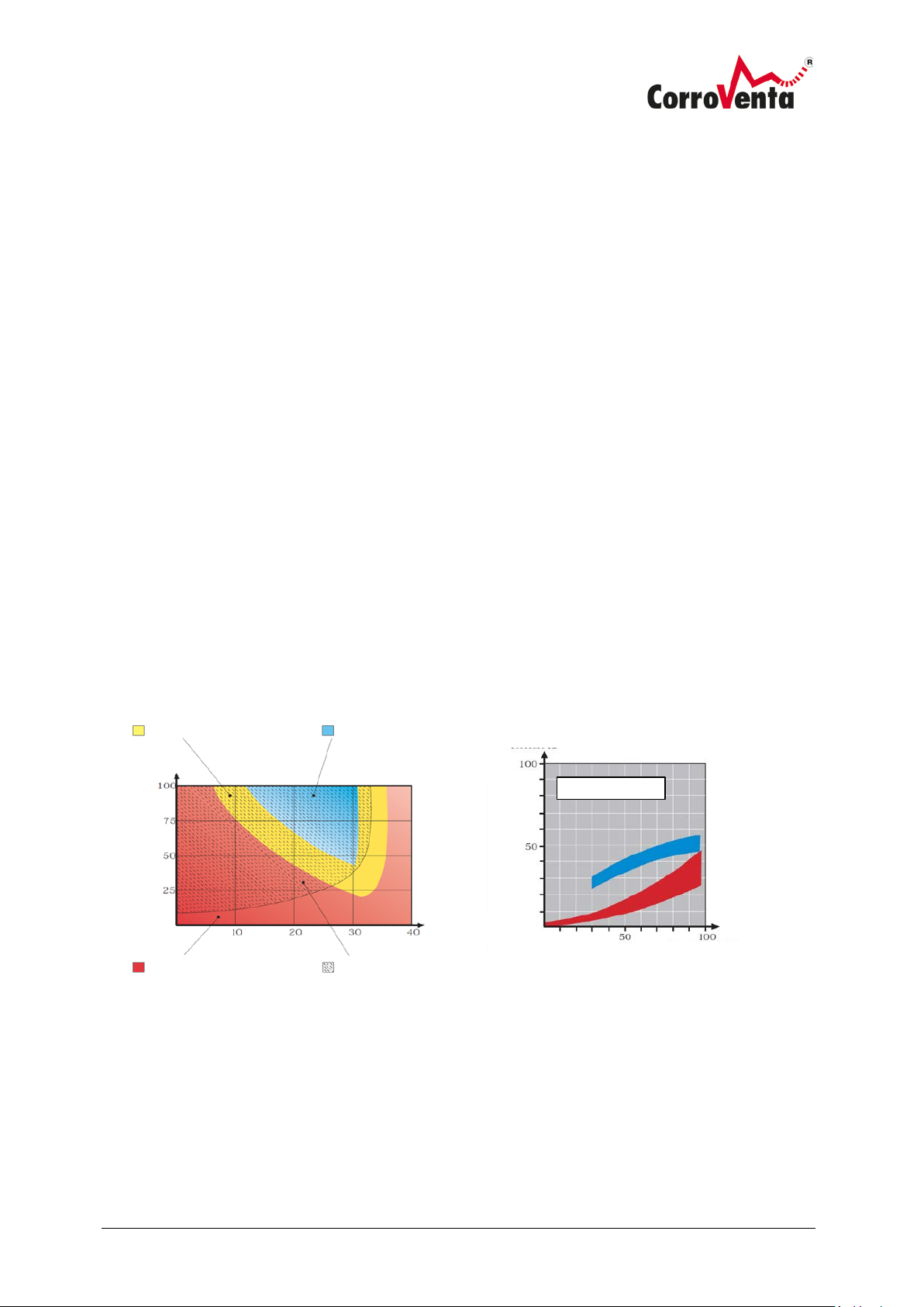
The adsorption principal has, compared to condensation drying, the advantage of a lower ambient
temperature dependency. Adsorption functions even well below the freezing point while the capacity
of a condensation dryer inevitably decreases rapidly with falling temperature, something that is
depicted in the diagram below to the left.
As a rule of thumb, a general aid in the selection of type, it can be said that adsorption is the primary
choice for drying of unheated spaces or when material is to be dried. The latter is motivated by the
fact that the adsorption dryer produces dryer air, generates a greater reduction of water content
measured in grams per kilogram (Δx), easily deduced from the diagram below to the right and
something that is directly correlated to the drying speed. Drying of layered constructions such as floor
structures are, with advantage, dried with combined use of turbines, high pressure fans, installed for
either suction or pressure drying.
Condensation dryers are, in accordance with the diagram above, used in hot and humid conditions
provided the goal and aim is drying of rooms, ambient air.
Page 8
© Corroventa Ltd.
2017.02
6 (25)
Turbine CTR T ES
1 pc
Spare cooling air filters
4 pcs
Manual
1 pc
Cooling air
Durable poly-urethane
Inlet
Control Panel
Outlet
Foldable carrying
Locks,
Power switch, on/off
Delivery inspection
CTR T ES is delivered with the following items included:
Product Overview
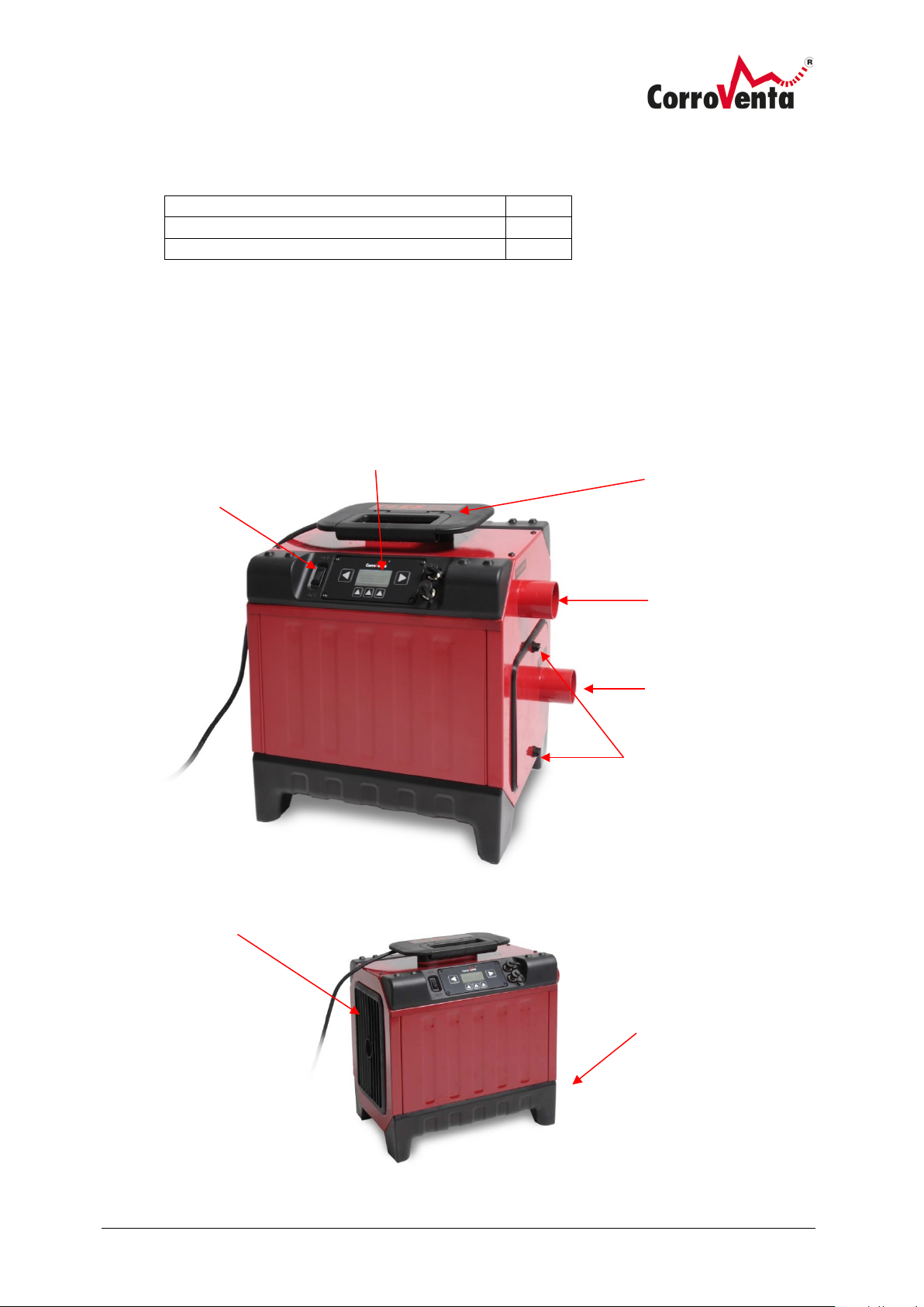
Below pictures present CTR T ES with all its external features and controls. The CTR T2 ES is shorter
than the CTR T4 ES but all the external features are the same.
handle with
integrated cable
parking
Process air
filter hatch
filter hatch
feet
Page 9
© Corroventa Ltd.
2017.02
7 (25)
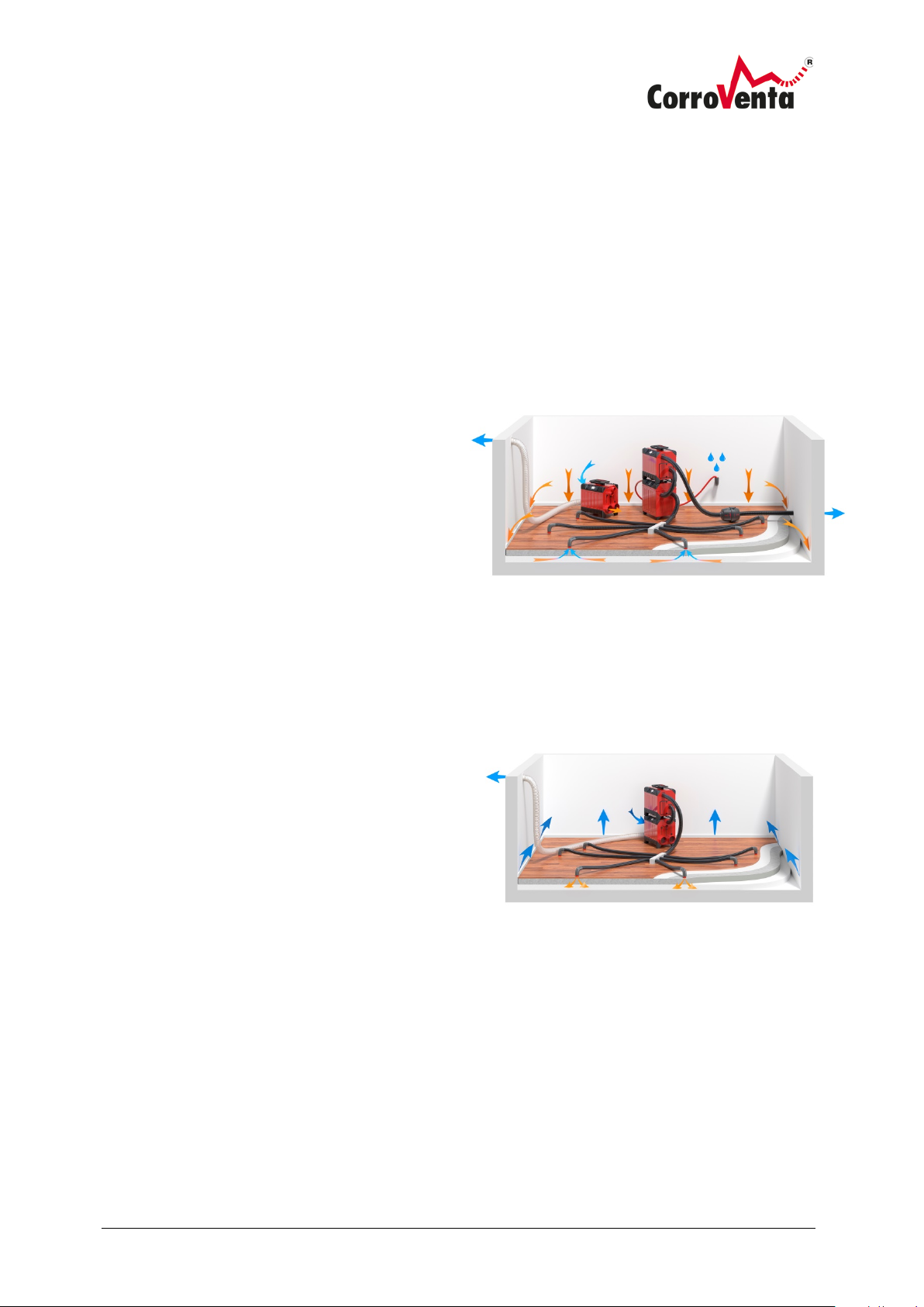
Pressure drying. The turbine is fed with dry air from the
dehumidifier and presses this air into the layered
construction.
Suction drying. The dryer dries the ambient air and the turbine
draws and evacuates air from the construction. The resulting
underpressure in the construction draws dry air into it.
Drying methods
The turbine CTR T ES is, in combination with adsorption dryer, used for suction and pressure drying.
The reason for the use of an adsorption dryer is that both suction and pressure drying are all about
drying material and the speed of that process is dependant of the difference in water contents (Δx),
measured in grams per kilogram, between the material and its environment. Adsorption dryers
produce dryer air, generates a greater reduction of water contents measured in grams per kilogram)
which increases the speed of the drying process. With pressure drying, warm and dry air is pressed
down into the construction making the construction temperature rise which increases the speed even
further and is the reason for it being faster than suction drying.
Suction drying
For suction drying the turbine is installed so that
it draws air from the construction through hose,
water separator and filter and then evacuates
this, normally outdoors. Use of water separator is
critical to prevent water from being sucked into
the turbine and damage its motor.
The dryer is installed for normal drying of room.
Pressure drying
For pressure drying, the turbine is installed so that
it is fed with dry air from the dryer and then presses
this down into the construction. This makes the
construction temperature rise and the drying goes
faster. Wet and cooled air leaks into the room
through drilled holes or gaps between the floor and
the walls and then returns to the dryer as process
air.
Before pressure drying is applied, suction drying
shall be used to remove any free water from the
construction and thus avoid pushing this into other
parts of the building. The initial removal of free
water also saves time.
Pressure drying might free particles/fibers from the construction and thus release them in the air. If
this is a potential problem, another method should be applied.
Page 10

© Corroventa Ltd.
2017.02
8 (25)
Installation
The CTR T ES shall be placed and installed leveled and in a stable position so that it does not fall over
and cause damage to the machine itself, person or property.
For suction drying, a water separator shall be used and connected to the hose prior to the turbine so
that water is not sucked into the turbine as that will damage the motor.
For pressure drying it is important to verify that the capacity of the turbine does not exceed that of
the dryer, that the latter’s dry air volume matches the turbine’s throughput. If not, too much air will
be drawn through the dryer and its capacity will decrease dramatically. If using a CTR ES version
dryer, this is verified by observing that the wet air volume is correct. When using one of these
machines, there is also the possibility of networking them, using the turbine as Master, and setting
the slaved adsorption dryer to pressure drying mode. In this mode, the dryer will automatically adjust
to the air volume that the turbine is pushing.
Verify that the cooling air filter is clean and not clogged by dirt. If required, replace the filter before
the work is commenced.
Contrary to its predecessors, the CTR T ES is not equipped with a manually resettable overheating
protection as this no longer is necessary. The turbine provides itself with cooling air and prevents
overheating by automatically adjusting its speed if the temperature should still rise too high. For best
drying performance, the user should however still verify that the airflow through the construction to
be dried is correct.
Installation in short, main points:
1. Put the turbine in a leveled and stable position so that it does not fall over and cause
damage.
2. Check the process air filter and the cooling air filters and replace them if necessary. Connect
the hoses configured for the drying to be undertaken. If free water might be present in the
construction to be dried, use Water separator to prevent water from being sucked into the
turbine.
3. Connect the cable to a 1-phase, 230 VAC socket with a 10A or maximum 16A fuse. As the
machine is normally used in humid or wet spaces, the use of a ground fault circuit interrupter
is strongly recommended.
4. Put the power switch in position On. When the display has started up, for new job with
default settings, push Start. To operate with the same settings as last time the machine was
used, push Resume.
5. Adjust the speed until desired air flow is obtained.
Page 11
© Corroventa Ltd.
2017.02
9 (25)
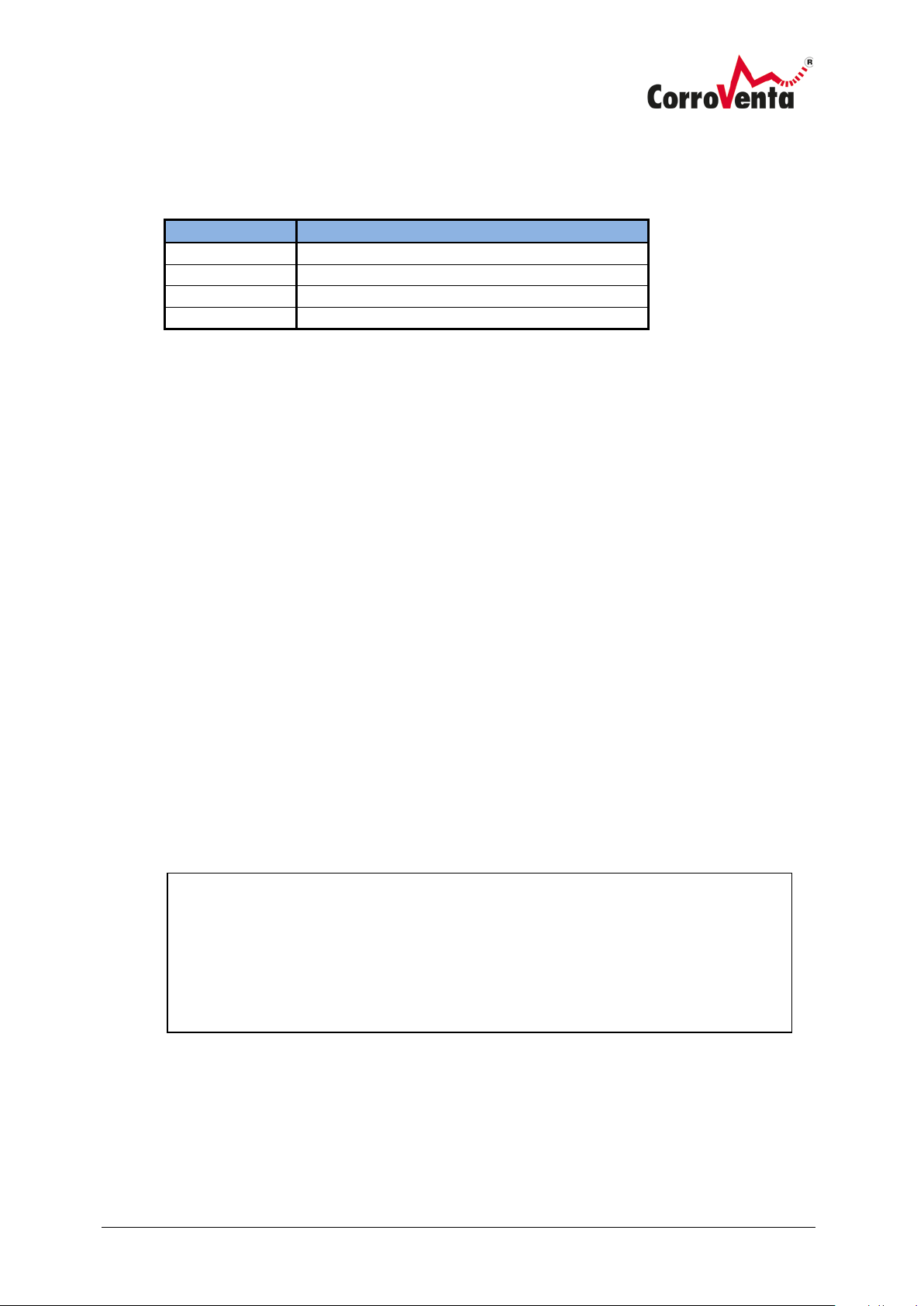
Article number
Name
1001238
Cooling air filter
6000371
Process Air filter
1002749
System cable, 0.5m
1002748
System cable, 5m
Top left and right buttons – Menu navigation only. Never changes any
Accessories and consumables
The following articles are available as accessories and consumables to the CTR T ES:
To Use CTR T ES, menus and operation
The CTR T ES has an easily understood user interface with a display and five push buttons. The two
larger buttons on the respective sides of the display are used to select between the different menus
– no changes to the setup can ever be made with these buttons as they are for navigation only.
The three smaller buttons below the display are used for selection and editing. At the top level
menus, the left of these buttons is named Home and a push on this button will immediately lead
back to the default view, something that can be good to remember if unfamiliar with the menu
system. In many of the views there is an Info button which presents information that may be of use
to the inexperienced user.
If the backlight of the display has timed out, the first button push serves only to light up the display.
After 10 minutes, if no button is pushed, a key pad lock is activated. The machine is then unlocked by
simultaneous push of the two upper buttons, something that is presented in text as well as picture
on the display.
Home button Return to the default view
Info button Presents information. On-board manual
settings.
Page 12
© Corroventa Ltd.
2017.02
10 (25)
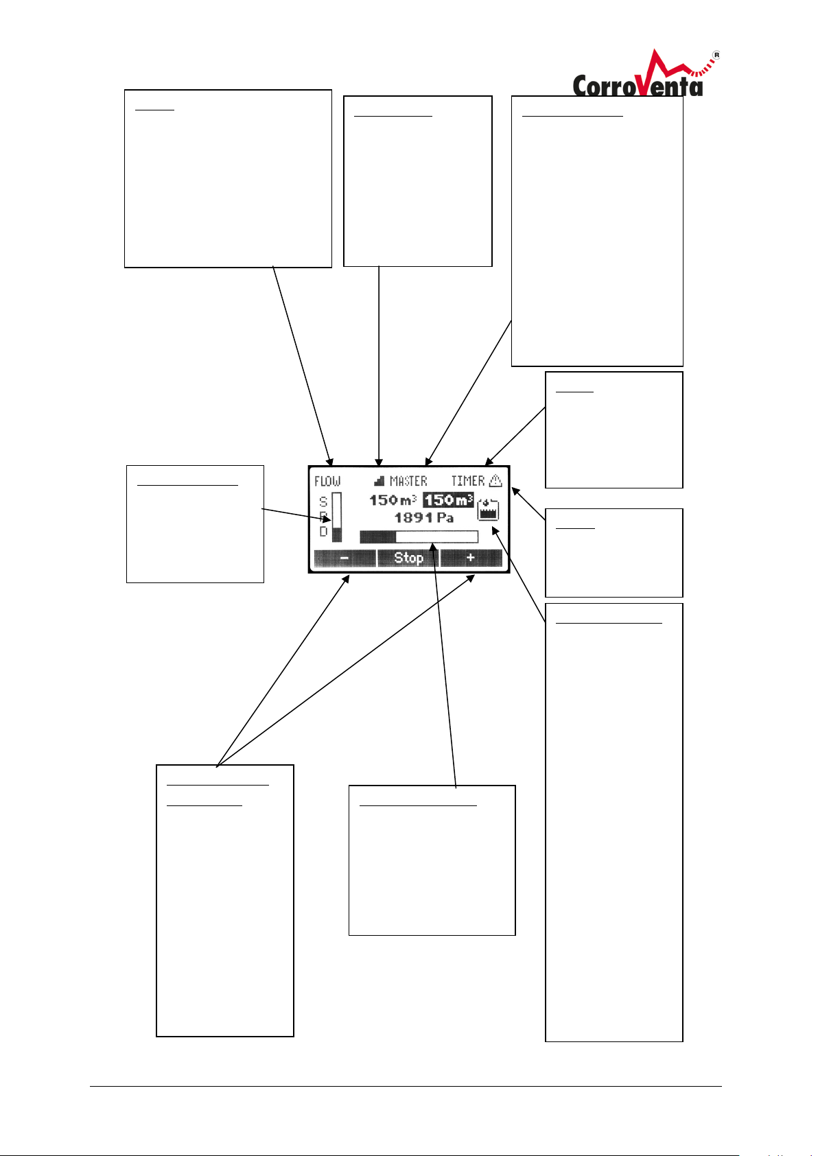
FLOW
SuperVision
Network status
Timer
Alarm
Speed indicator
Water separator
Pressure indicator
Speed/setpoint
adjustment
This text is visible when the
machine is set to flow mode
and maintains constant
airflow by automatically
regulating the turbine speed.
Visible when the
machine is
connected to
SuperVision for
remote monitoring
and control.
“Master” or “Slaved”
If the machine is
connected to local
network, this position
indicates whether the
machine is controlling
the network, Master, or
if it is controlled by
other machine and thus
Slaved.
Indicates what
speed the turbine
is operating at.
indicates that the
left and right
buttons below the
screen are used to
increase and
decrease the
setpoint which is
displayed with
black background.
Visible when
machine is set to
operate on Timer.
Machine has
detected an error.
Visible when the
machine is
connected to WS 4
ES water
separator through
system cable,
allowing the
turbine to count
the number of
Visualization of current
differential pressure vs
the maximum
achievable pressure at
the selected speed.
times the water
separator has
pumped and also
to present when it
last pumped which
is useful for
evaluation of
drying progress.
time of the last
pump.
Page 13
© Corroventa Ltd.
2017.02
11 (25)
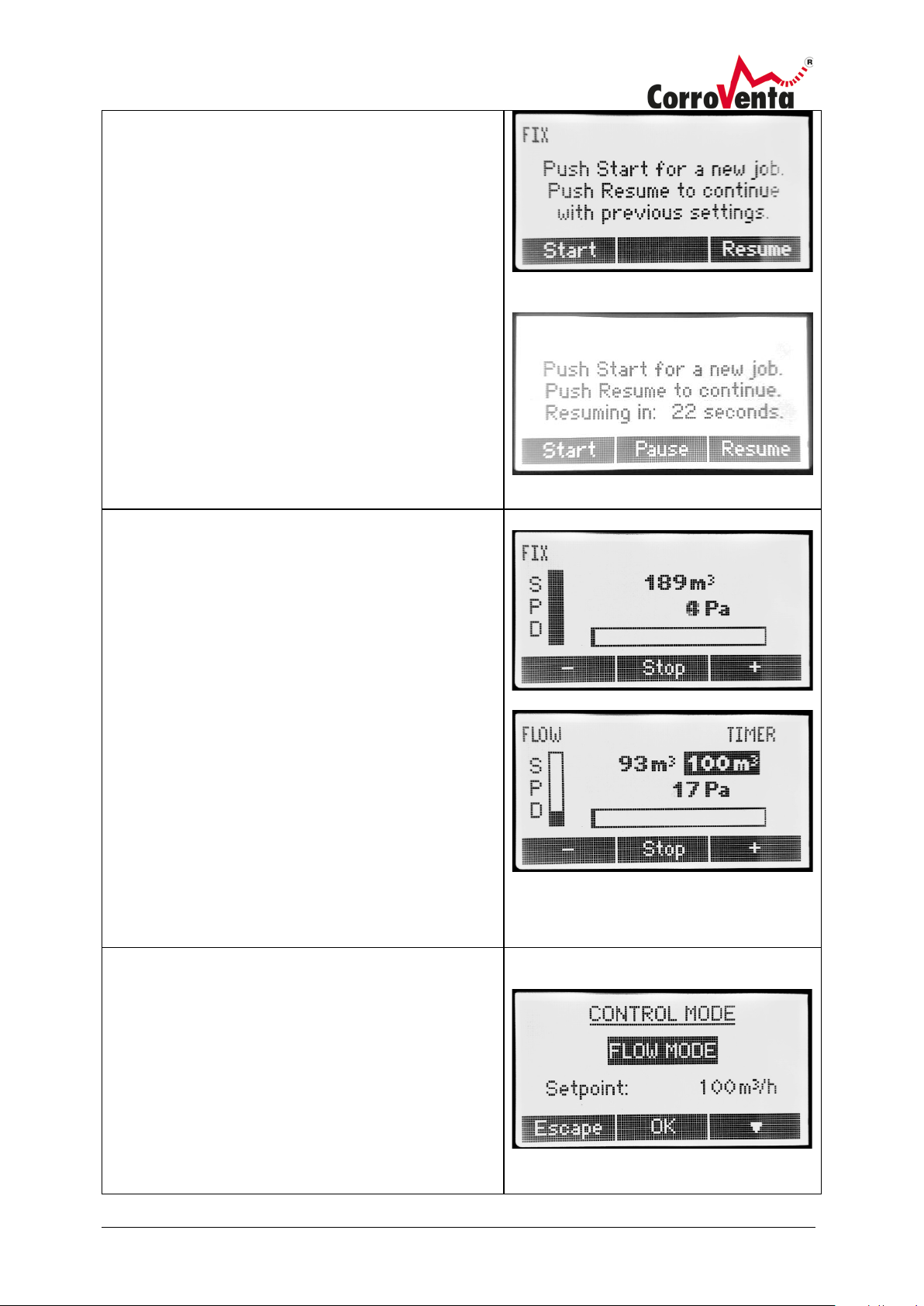
Start up view
Start:
Resume:
Default View
Control Mode
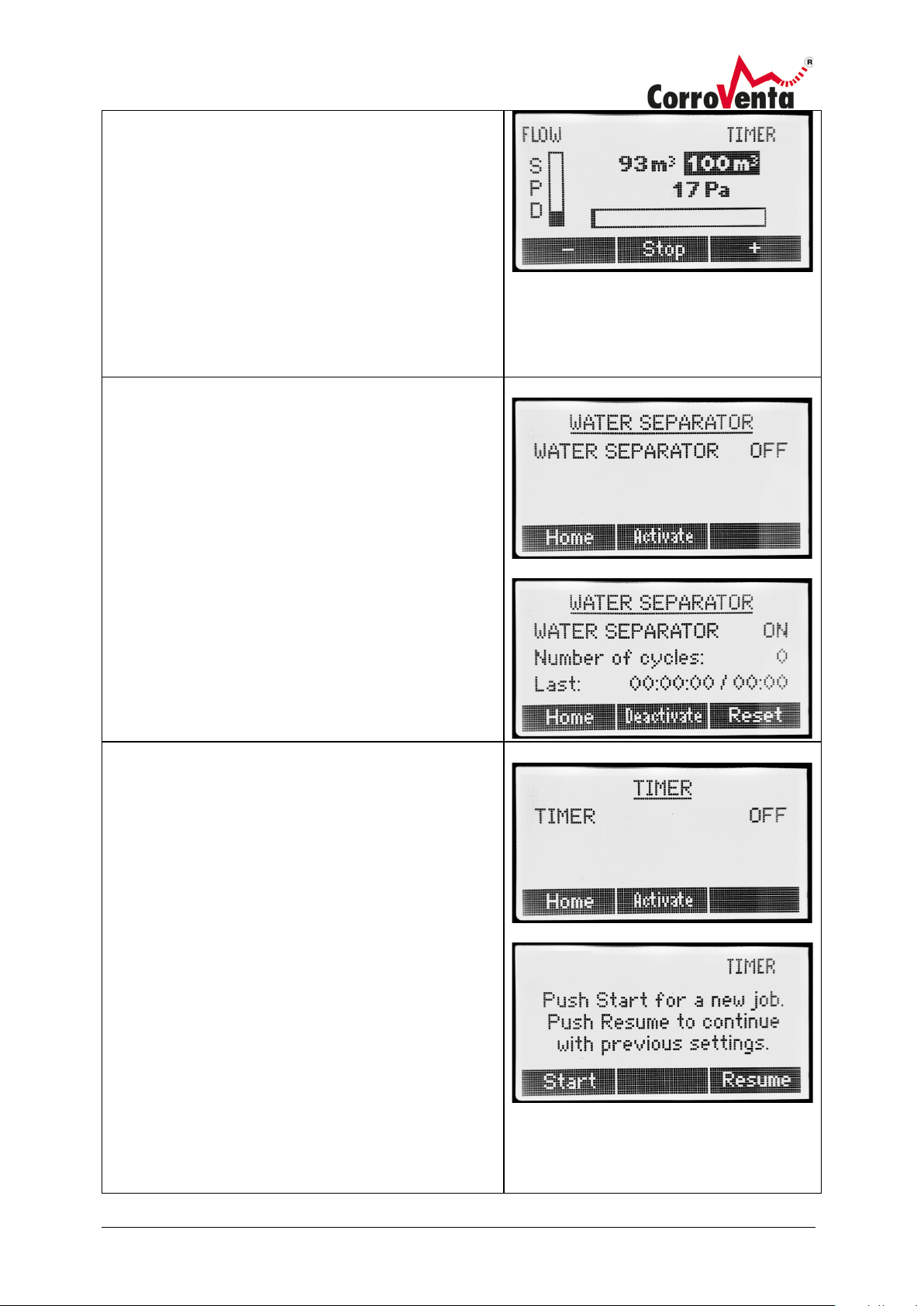
When the T ES starts up, the display presents the user
with two options:
Starts the machine at default speed. Previous
settings made such as Timer and Flow settings are
discarded.
The machine resumes operation with the
Normal start
settings it had last time it was used.
If, last time it was used, the user never pushed stop
before the power was cut, the machine will
automatically resume operation when the countdown
has reached zero.
Start med timer
When the T ES is operating, the machine can always be
stopped, set to standby, by use of the center button
below the display.
When the Turbine is operating on fixed speed, the left
and right buttons below the display are used to
decrease and increase the speed level. The current
speed level is depicted on the vertical bar to the left.
The horizontal indicator presents the current pressure
level compared to the maximum pressure achievable
for the given turbine speed.
When set to flow mode, the left and right buttons
below the display changes the setpoint flow,
highlighted with black background. The same principal
applies to Relation mode which can be used when the
machine is used in a network and slaved to another
Turbine.
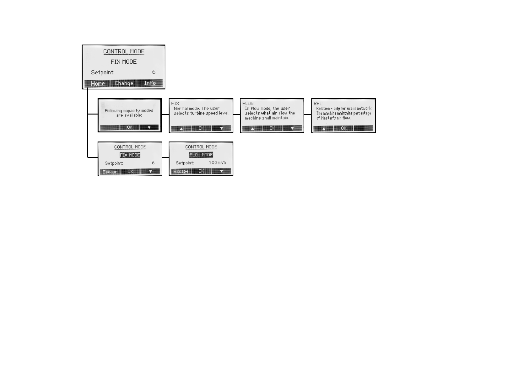
The machine can operate in three different control
modes, Fix, Flow and Relation. In Fix mode, the user
selects a fixed speed level for the turbine. In Flow
mode, the user instead selects what air flow shall be
maintained and the machine will then automatically
adjust the turbine speed to maintain that airflow even
if the counter pressure changes.
The third option, Relation, is only available when the
machine is networked and slaved to another turbine.
Page 14
© Corroventa Ltd.
2017.02
12 (25)
The Relation mode functions like the Flow mode, the
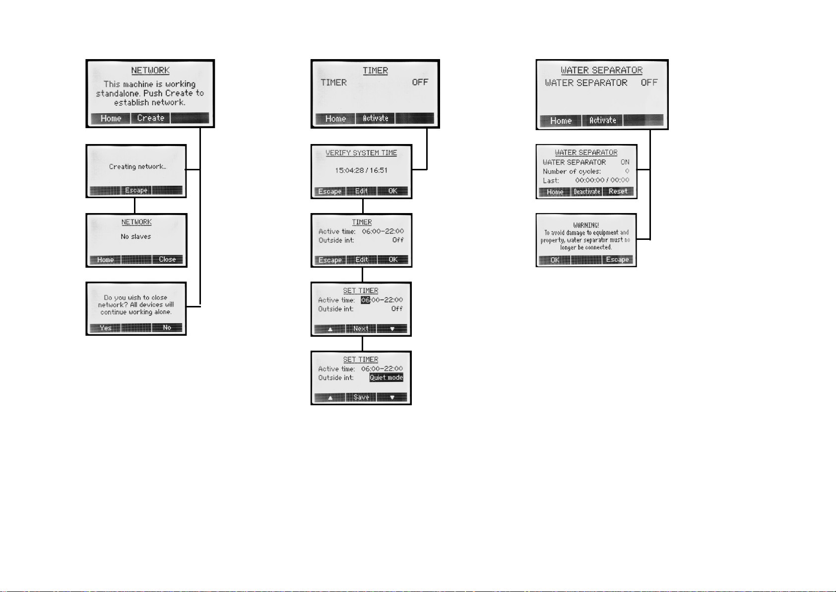
Water Separator
Note:
Timer - on/off and quiet mode
only difference being that instead of defining a certain
air flow, the user selects what percentage of the
Master machine’s air flow the turbine should maintain.
To select Control Mode, push Change and then use the
right down arrow button to select mode. Push OK to
confirm the selection. In the next step, adjust setpoint
as required.
The current Control Mode is displayed in the top left
corner of the default screen.
This functionality can only be used when the
turbine is connected to a WS4 ES Water Separator.
If the turbine is connected by power cable and by
system cable to a WS 4ES, the turbine can register how
many times the water separator is emptied so as to
allow the user to calculate how much water has been
removed. In addition, the turbine can also present at
what date and time the water separator was last
emptied in order for the user to assess whether or not
there is any more water to be removed.
If this functionality is activated there when there is no
WS 4ES connected, the turbine will remain in standby.
If, for some reason, the machine must not operate
continuously but for instance only day time or night
time, the machine can be set to operate on Timer.
For the remainder of the time, the machine can be set
to turn off completely or to operate in quiet mode.
In quiet mode, the speed of the turbine is reduced to
approximately level 4 in order to minimize noise.
When Timer is selected, the word Timer is displayed in
the upper right corner of the default screen.
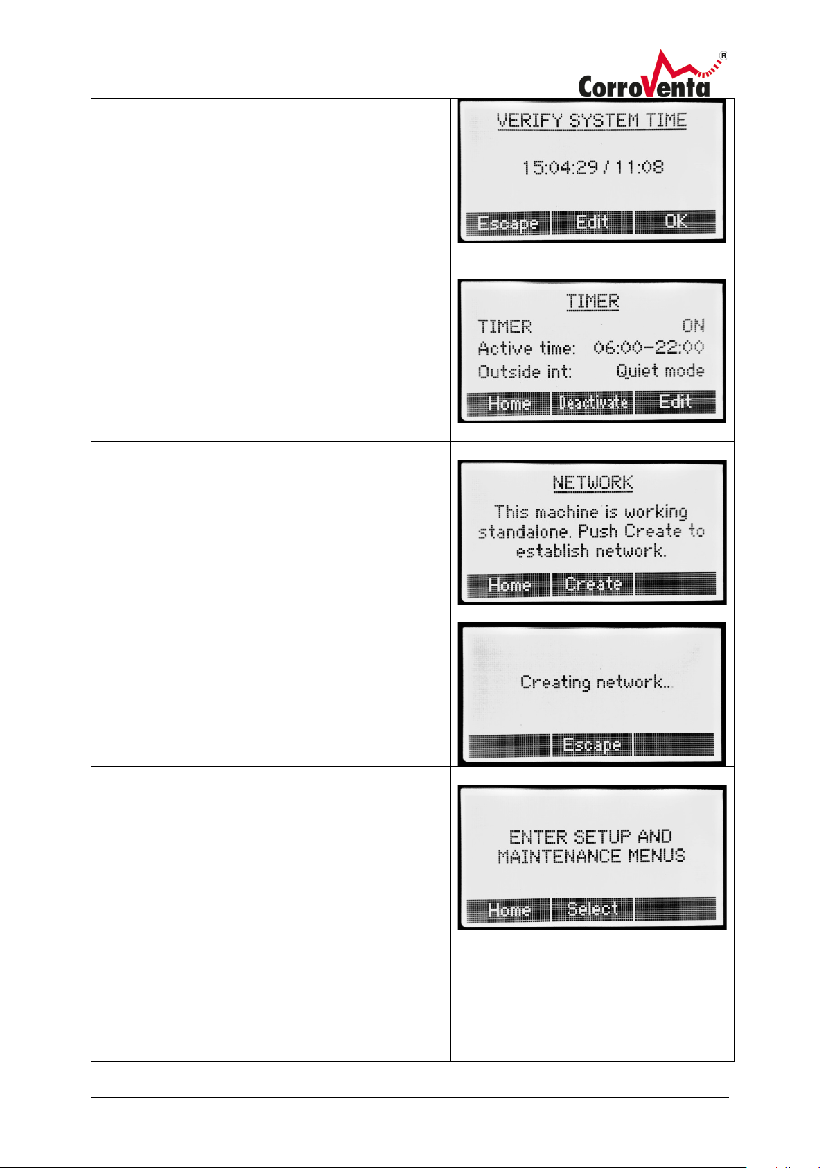
To activate Timer, enter the Timer menu and push
Activate.
Confirm or, if required, edit the system time and date
which is presented in the following format:
YY:MM:DD / HH:MM.
Push OK.
Page 15
© Corroventa Ltd.
2017.02
13 (25)
The Timer function is now activated with the settings
Network
Setup and Maintenance Menus
Date and Time
Language:
Menu System:
Key Pad lock
presented. If the settings are incorrect, push Edit and
use down and up arrows to change the settings.
Confirm each selection with the push of Next.
The last parameter, Outside int, controls what the
machine shall the remaining time, outside the interval.
It can be set to either Quiet Mode, in which the
machine operates at reduced speed, or Off where
naturally the machine will stop and remain in standby
until it restarts at selected start time.
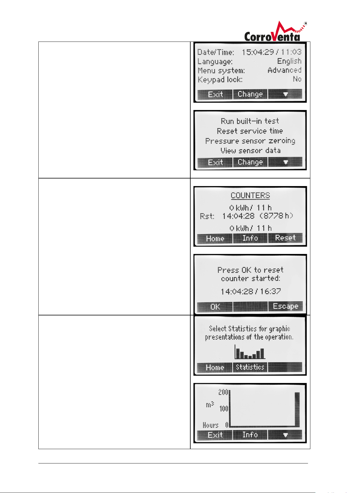
Note: Install all the system cables before powering up
the machines.
To use this machine as a Master on local network, in
the Network menu, push Create. The creation can take
up to one minute.
When the creation process is through, a slave selection
menu is presented. If there is no need to change the
settings on any of the slaves, push Escape.
If changes are required, push Select and use the left
and right arrow buttons to choose the machine to edit.
When selecting a slave, its display backlight will start
blinking as an acknowledgement to the user.
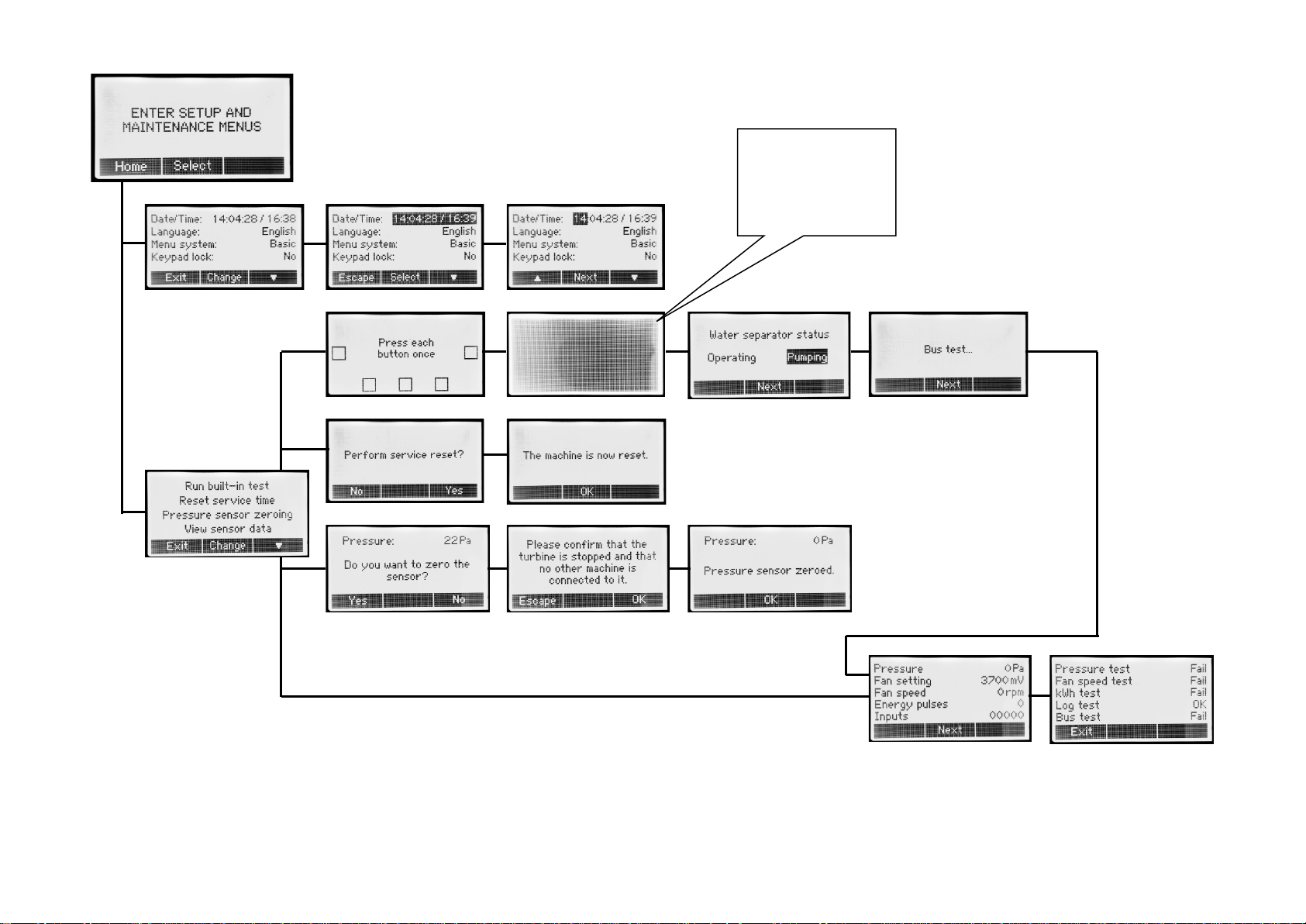
Under Setup and Maintenance, functions that are not
required for normal operation are found.
: Setting of system date and time.
Format is YY:MM:DD / HH:MM.
Selection of language for the interface.
The menu system is by default set to
Advanced with all functions visible and accessible. If
set to Basic, the more advanced functions, flow are
removed from the menu system.
: Possibility to deactivate the key pad
lock.
Page 16
© Corroventa Ltd.
2017.02
14 (25)
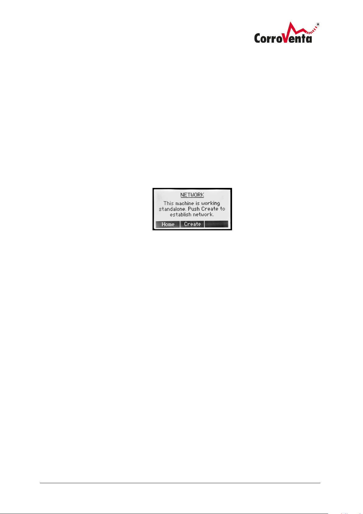
Run built-in test:
Reset Service Time:
Pressure sensor zeroing:
View sensor data:
Counters
Statistics
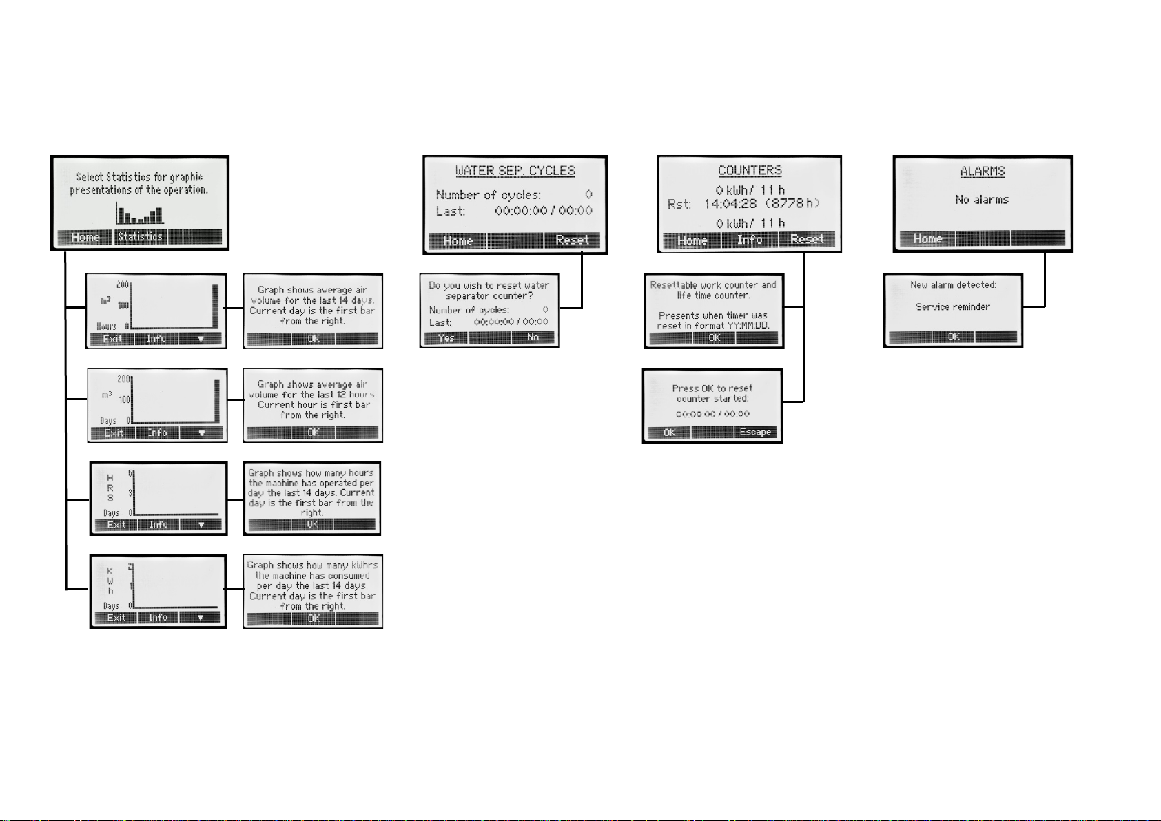
graphs, is the current hour or current day as applicable.
A built-in self-test that is available
for service technicians.
The machine is set to give a
service reminder once every 12 months. When service
has been performed, this service reminder can be reset
using this function.
Functionality allowing
zeroing of pressure sensor to eliminate drift that can
occur over time. Must only be used when the machine
is stand-alone, not connected by hoses to any other
machine and also with clean process air filter.
Functionality intended for service
technicians.
This screen presents the hour and energy counters.
At the top, the resettable work counters are presented,
followed by the date at which the counters were reset.
After the date, the number of hours elapsed since this
reset is presented so as to allow for a quick
comparison.
To reset the work counters, push Reset. Acknowledge
the intent to reset the counters by push of OK in the
following confirmation screen.
At the bottom, the machine life time counters for
energy and hours are presented. These counters are
not resettable.
Statistics are provided to assist the user in studying
the progress of the drying process and to allow for
monitoring and follow-up of the operation of the
machine.
Found under the statistics menu are the following
graphs:
• Average air volume for the duration of
operation during the last 12 hours and for the
last 14 days respectively.
• Operation hours for the last 14 days
• Consumed energy, kWhrs, for the last 14 days.
The last value, the bar at the far right in the respective
Page 17

© Corroventa Ltd.
2017.02
15 (25)
Network functions
As a member of the new CTR ES family of machines, the T ES can be networked with other turbines
and adsorption dryers which provides extended functionality including:
• Relation – cooperation between two or more turbines with defined relation between the
respective air flows.
• Optimized pressure drying, a mode of operation where the slaved adsorption dryer
automatically adjusts to the turbine air flow producing as dry air as possible.
• Operation on common timer
• Interoperability with future SuperVision system allowing remote monitoring and control of
machine operation.
The networking of machines requires no pre-configuration or other preparations. When installed, the
machines are simply connected with system cables and then a simple push of the Create button in
the Network menu of the intended Master machine is all that is required. The Master is the machine
selected to control the others and all machines can be used to this purpose. For use of Relation and
Pressure drying modes, the Master needs to be a turbine but for other purposes it does not matter
what machine is Master on the network.
While a machine is slaved to another unit, its settings can still be changed on the machine itself and
not only through the Master. If the user selects to do necessary changes to the settings through the
Master, the display of the selected Slave flashes while the changes are made so as to allow for easy
identification and avoid confusion.
Page 18
© Corroventa Ltd.
2017.02
16 (25)
How to network machines
In order to network machines to use for instance the pressure drying mode of the dehumidifier,
proceed as follows:
1. If the machines are powered, switch them off and then proceed by connecting the machines
with system cables. The two connectors on the machines have the same functionality so it
does not matter which one is used. If SuperVision is to be used, this too must be connected
to one of the machines, it does not matter which one.
2. Power up the machines.
3. Select what machine shall be master, for use of pressure drying mode, this shall be the
Turbine set to push the dry air into the construction.
If networking the units with the only purpose of having them monitored and remotely
operated through SuperVision, it does not matter what machine is selected as Master.
4. On the selected Master machine, use right arrow button to step to the Network menu
depicted below.
(If this menu is not found, the machine is set to Basic menu setting. To change this, select
Setup and Maintenance menu and change the menu system setting to Advanced.)
5. In the Network menu, push <Create> and then wait while the machine sets up the network.
6. When the network is created, at the top of the screen the presentation will toggle between
the different slaves. If SuperVision is connected, the text SuperVision will be presented at
the bottom of the screen although it can take up to a minute before this is shown.
After having followed the steps above, all the slave machines are now controlled by the Master.
This means that they will all be started and stopped with the Master. They still work with the
same settings they had before the network connection so if these need to be changed, push Edit
and then select the slave to be edited through the Master or do the necessary changes to the
settings on the machine itself. When being edited through the Master, the slave machine will
start to blink its display backlight so that the user can see what machine is selected.
Page 19
© Corroventa Ltd.
2017.02
17 (25)
Alarm
Action / Advice
One or more slaves are not
This alarm is presented when the machine, used
Water separator pumping time
This alarm can be displayed when the turbine is
Air flow is too low
If displayed the turbine is running with too much
Mainboard connection failure
Internal error. If it remains, please contact service
Pressure sensor failure
Internal error. If it remains, please contact service
Failed to save the statistics
Internal error. If it remains, please contact service
Failed to save the event log
Internal error. If it remains, please contact service
technician.
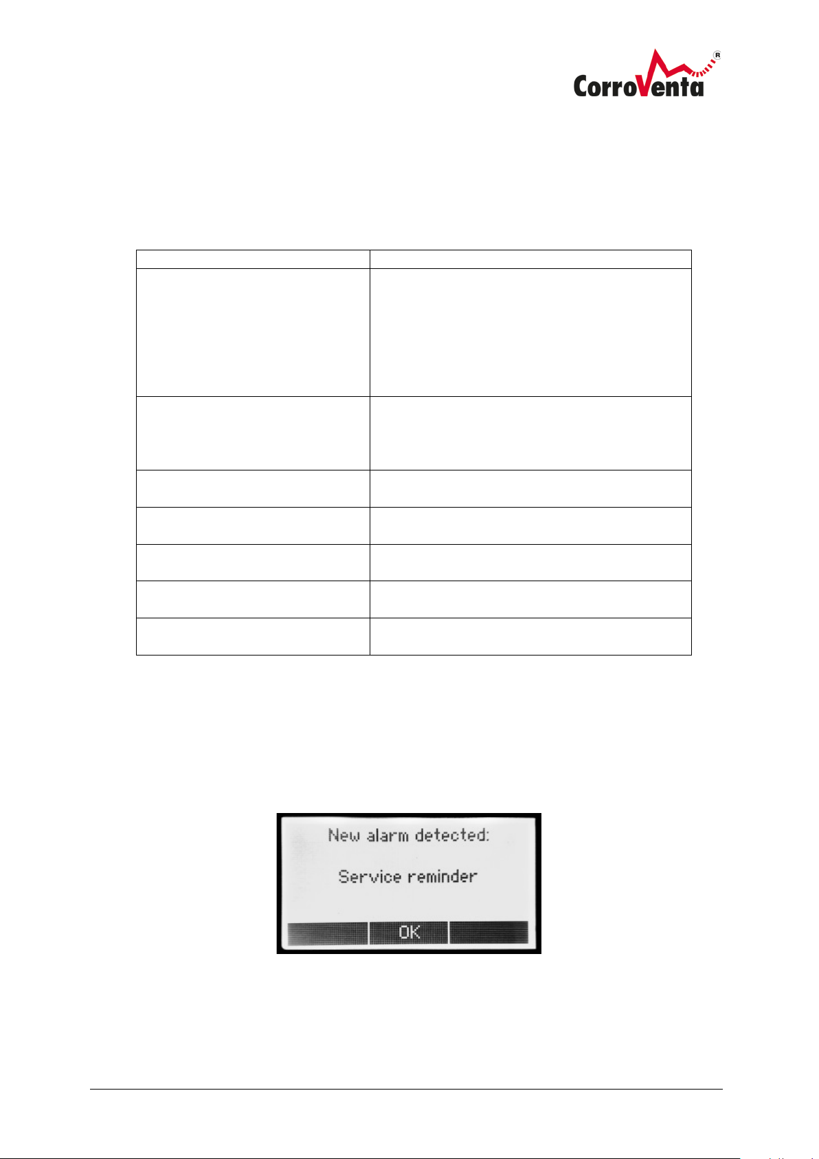
Alarms
If the machine detects an error, this information is presented in a pop-up screen and for as long as
one or more problems exist, there is a warning symbol in the top right corner of the default view.
The alarms that can be displayed are the following, each presented with recommendation on what to
do.
responding
as Master on a network, has lost connection with
one or more of its slave machines. If it is
presented, check all the system cables and the
power to the respective machines. As soon as
communication is re-established, the alarm will
automatically disappear.
limit
used with a WS4 ES water separator. If displayed,
check the water separator to see why the pump
has not succeeded in emptying the machine.
counterpressure. Check the installation.
technician.
technician.
technician.
Service Reminder
The machine is set to provide a service reminder every twelve months. The reminder is presented as
an alarm but it does not affect the operation of the machine. The service reminder function is reset
under Setup and Maintenance.
Page 20
© Corroventa Ltd.
2017.02
18 (25)
Turn knob anti-
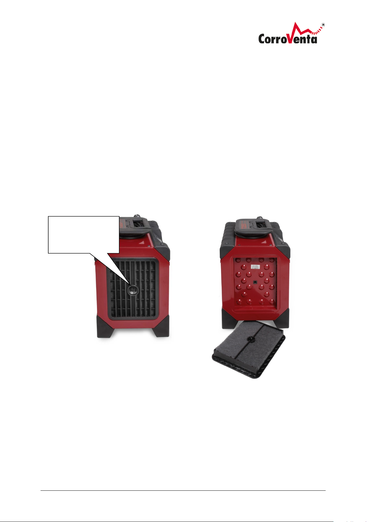
Maintenance and service
The turbine’s air filter shall be replaced regularly, suitably between every installation, every work, that
the dehumidifier is used for. When used in dirty environment, the filter needs to be replaced more
often.
1. Disconnect power to the turbine - remove its cable from the socket.
2. Turn the knobs of the filter hatch anti-clockwise to open it. Pull out the dirty filter and insert
the replacement filter. Close the hatch by turning the knobs clockwise.
3. Reconnect power.
The cooling air filters shall be replaced regularly, suitably for each new job. In very dirty environments
even more frequent replacements can be necessary.
4. Turn the knob anti-clockwise to remove the filter holder.
5. Remove and discard the old filters, install the new ones.
6. Put the filter holder back in position.
clockwise to remove
filter holder.
Page 21

© Corroventa Ltd.
2017.02
19 (25)
Symptom
Probable cause
Action
Turbine speed
varies, it shuts down
and restarts again
The turbine is too heavily
Inspect the installation and all filters, both
The turbine makes
noise, does not
sound the way it
normally does.
Bearing in motor is worn
Please contact your retailer for repair.
The turbine has
stopped/ does not
start.
No mains power.
Check that power cable is connected and that
Fault finding
loaded, the resistance
through the construction or
the hoses is too high due to
too few suction/pressure
points, squeezed or clogged
hoses, and/or clogged filter.
that of the turbine itself and the others in
the system. Verify that they are clean and
are not stopping the flow. Verify that no
hoses are squeezed or clogged with dirt.
Make and install additional suction or
pressure points depending on installation.
Drill further holes and connect additional
hoses or whatever is appropriate and feasible
to decrease the resistance and increase the
flow.
and/or damaged.
Built-in overheating
protection triggered.
Turbine failure.
the power outlet is live, that the fuse and, if
present, the ground fault circuit breaker are
in order.
Disconnect power by pulling the cable from
the socket and let the turbine cool down for
15 minutes. Reconnect the power and start
the turbine.
If the above does not rectify the operation,
please contact your retailer for repair.
Page 22
© Corroventa Ltd.
2017.02
20 (25)
Air volume (m3/h)
Up to 180
(continuously variable)
Pressure (mbar)
Up to 260
(continuously variable)
Noise, dBA (3m)
approx. 48 *
Voltage
230 VAC / 50 Hz
Rated power (W)
1100
Height x width x length (mm)
430 x 295 x 370
Weight, kg 14
Air volume (m3/h)
Up to 300
(continuously variable)
Pressure (mbar)
Up to 260
(continuously variable)
Noise, dBA (3m)
approx. 48 *
Voltage
230 VAC / 50 Hz
Rated power (W)
1800
Height x width x length (mm)
430 x 295 x 430
Weight, kg 17,5
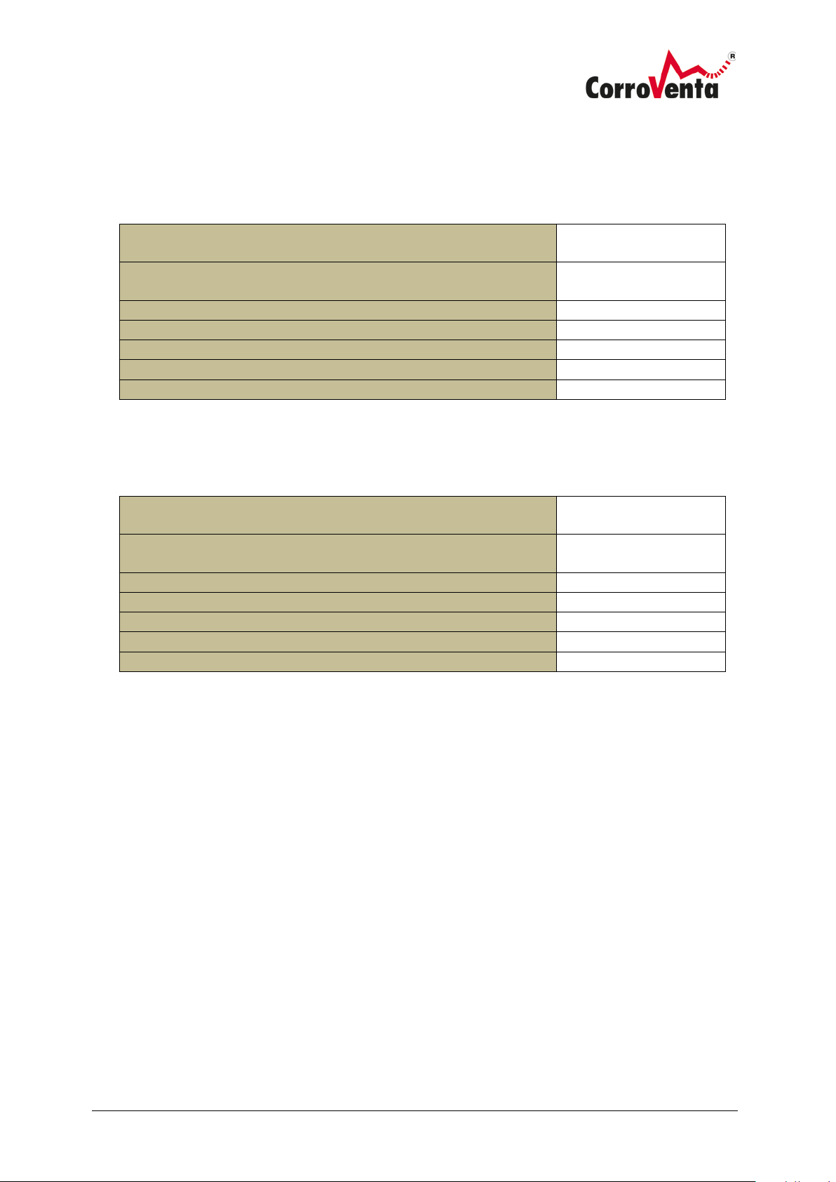
Technical data
CTR T2 ES
Typ LAF 50 LAF 50E LAF 50E2 LAF 100 LAF 100E LAF 150 LAF 150E
*Noise level varies with installation.
CTR T4 ES
*Noise level varies with installation.
Page 23
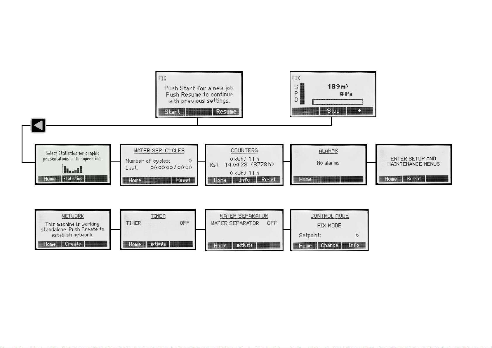
Interface Map for CTR A2ES, CTR A4 ES and CTR A ES
Top Menu
Page 24
Info
Statistics
Info
Info
Info
Reset
Reset
Info
Sublevels
Page 25
Select
Change
Change Reset…
Change Run…
Change Pressure…
Change View…
Functional test of
the display.
This is to test that
all pixels are active
Page 26
Create
Activate
Activate
Deactivate
OK
Edit
Page 27
Info
Change
Page 28
DO YOU HAVE ANY QUESTIONS OR DO YOU NEED OUR SUPPORT?
Please visit www.corroventa.com or call us at +44 (0)161-244 95 23 and speak to an expert.
We have the knowledge and the equipment to find a solution as eciently as possible.
Corroventa develops, manufactures, sells and hires out high quality products for
dealing with water damage, moisture, odours and radon. We are market leaders
and specialise in innovation within the industry. Our products are compact, eective, ergonomic and energy ecient. In emergency situations and during flooding,
Corroventa’s customers have access to one of the largest rental parks in Europe.
We have sales oces and machine depots in several locations throughout Europe.
All our manufacturing takes place in Bankeryd, Sweden.
www.corroventa.com
Unit 29, Irlam Business Centre, Irlam, Manchester,
CORROVENTA LTD
England, M44 6GP • Tel +44 (0) 161-2449523
www.corroventa.com
 Loading...