

Page 1
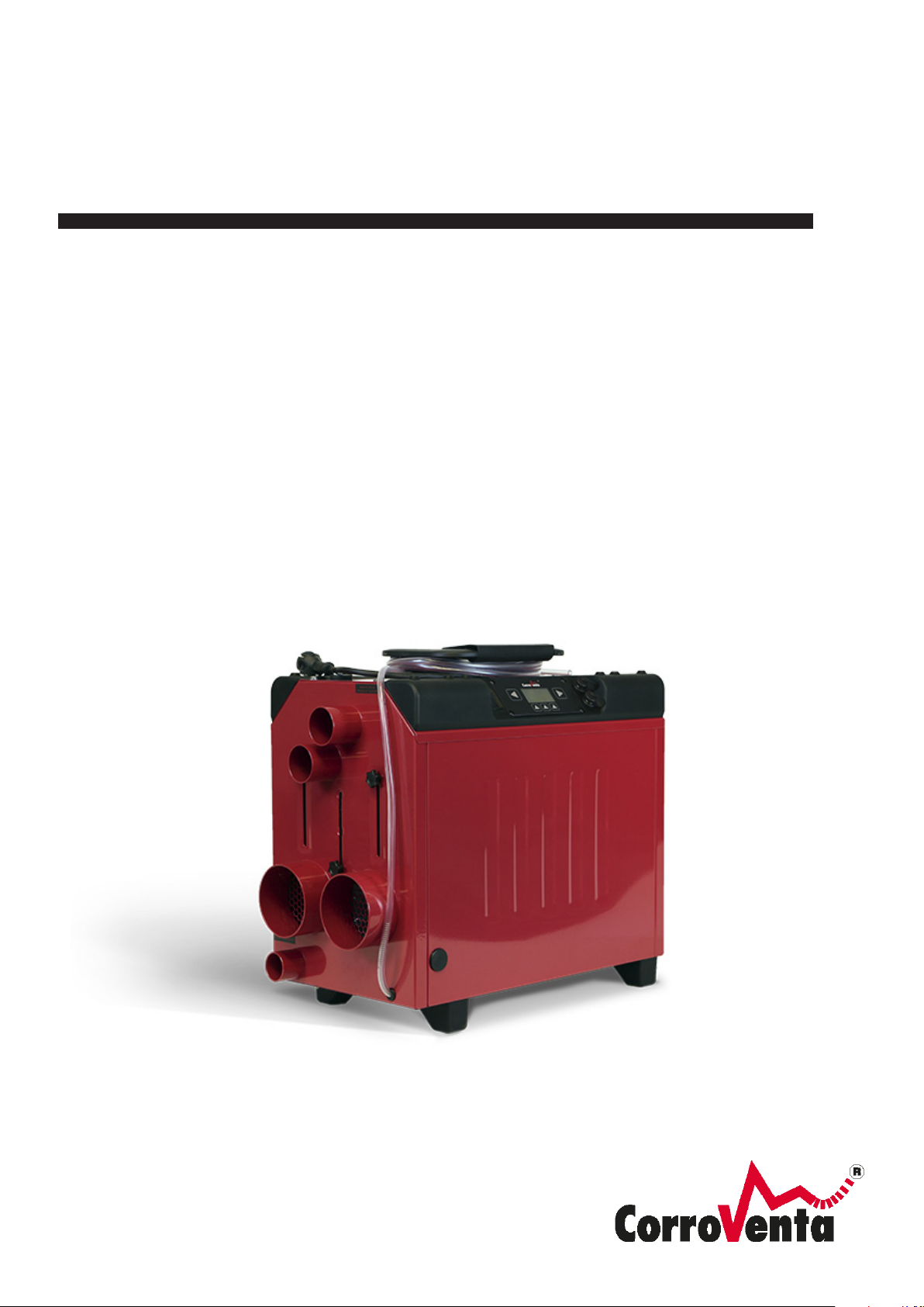
ADSORPTION DEHUMIDIFIER
WITH CONDENSER
L4 ES
USER MANUAL
Page 2
Description:
Manual L4 ES HP; L4 ES HP W
Document Number:
1004289
Created By:
MSHN
Revision Approval Date:
2019-06-28
Revision:
A
© Corroventa Avfuktning AB 1 (42)
Contents
Area of use ......................................................................................................................................... 2
Delivery check .................................................................................................................................... 3
Manufacture directive ......................................................................................................................... 3
Safety information .............................................................................................................................. 4
Relative humidity and its impact on materials .................................................................................... 5
How to select dehumidification technology for a given situation ....................................................... 5
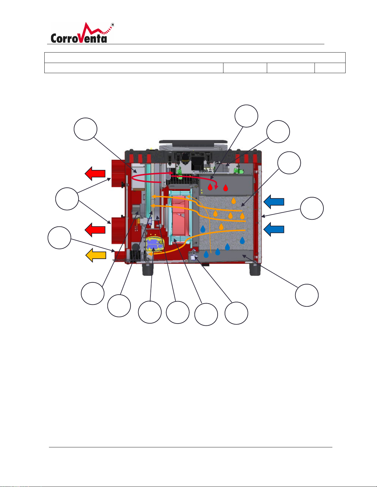
This is how the dehumidifier works .................................................................................................... 7
Dehumidification process ................................................................................................................... 7
Product overview ................................................................................................................................ 9
Installation ........................................................................................................................................ 10
Transportation .................................................................................................................................. 13
Storage ............................................................................................................................................. 13
Drying methods ................................................................................................................................ 14
General drying, room dehumidification ...............................................................................14
Drying framed flooring and beams .....................................................................................15
Suction drying ....................................................................................................................16
Pressure drying ..................................................................................................................17
Using L4 ES, menus and operation ................................................................................................. 18
Control mode and hysteresis ........................................................................................................... 29
Alarms............................................................................................................................................... 30
MID ENERGY METER MENU ......................................................................................................... 32
Network functions ............................................................................................................................. 33
Connecting machines to a network .................................................................................................. 33
Maintenance and service ................................................................................................................. 34
Service reminder ................................................................................................................34
Filter replacement ..............................................................................................................35
Cleaning the rotor insert. ....................................................................................................36
Accessories and consumables ......................................................................................................... 39
Page 3
Description:
Manual L4 ES HP; L4 ES HP W
Document Number:
1004289
Created By:
MSHN
Revision Approval Date:
2019-06-28
Revision:
A
© Corroventa Avfuktning AB 2 (42)
• Energy efficient
• Service-friendly
• High capacity level
• Digital interface with network function
• Robust
• Very quiet
•
• Energy and time meter – resettable work
counter
• Easy to transport
• Stackable
• Ergonomic
• Very compact
Fault tracing ...................................................................................................................................... 39
Technical data .................................................................................................................................. 41
User instructions L4 ES
Area of use
L4 ES is an adsorption dehumidifier with air-cooled condenser, developed and designed for construction
dehumidification and for drying water damage and is very practical for use in situations where it is
difficult to extract wet air from a normal adsorption dehumidifier.
Using the adsorption principle, L4 ES also works at low temperatures and by condensing in the aircooled condenser, the room is supplied with up to 400 W of extra heat.
Via the control panel, the user of L4 ES can optimise the operation for the intended job, set the capacity
and volume, control the fan as well as use integrated or external sensors for temperature and relative
humidity to achieve the desired effect in combination with the lowest possible energy consumption. L4
ES can also be used in networks and is prepared for remote monitoring and remote control.
Furthermore, it has a built-in pump, integrated hose and cable wind, as well as flexible support feet that
protect floor surfaces and at the same time allow stackability. Its robust design gives a long service life.
In addition to room drying, L4 ES can also be used together with turbines for drying layered
constructions, both suction and pressure drying.
Properties:
Low weight
Page 4
Description:
Manual L4 ES HP; L4 ES HP W
Document Number:
1004289
Created By:
MSHN
Revision Approval Date:
2019-06-28
Revision:
A
© Corroventa Avfuktning AB 3 (42)
Dehumidifier L4 ES
1 x
Extra process air filter in addition to the one in
the dehumidifier
2 x
Manual
1 x
Delivery check
L4 ES is supplied with the following parts in the package:
Manufacture directive
The machines in the L4 ES series are CE approved.
Limitation of Liability
• Incorrect installation and/or incorrect use can cause property damage as well as injury.
• The manufacturer assumes no liability for property damage or injury incurred as a result of
failing to follow these instructions, the machine being used for purposes other than those
intended or failure to observe these warnings. Such damage, injury or liability is not covered by
the product warranty.
• The product warranty does not cover consumable parts or normal wear.
• The purchaser is responsible for checking the product upon delivery and before use to ensure it
is in good condition. The product warranty does not cover damages resulting from the use of
defective products.
• Changes or modifications to the machine must not be performed without written permission
from Corroventa Avfuktning AB.
• The product, technical data and/or installation and operating instructions are subject to change
without notice.
• These user instructions contain information protected by applicable intellectual property laws.
No part of these user instructions may be reproduced, stored in a retrieval system or
transmitted to third parties in any form or by any means without the prior written consent of
Corroventa Avfuktning AB.
Any comments regarding the content of this document must be sent to:
Corroventa Avfuktning AB Tel: +46 (0)36-37 12 00
Mekanikervägen 3 Fax +46 (0)36-37 18 30
SE-564 35 Bankeryd E-mail: [email protected]
SWEDEN
Page 5
Description:
Manual L4 ES HP; L4 ES HP W
Document Number:
1004289
Created By:
MSHN
Revision Approval Date:
2019-06-28
Revision:
A
© Corroventa Avfuktning AB 4 (42)
Safety information
The equipment can be used by children over 8 years old and people with reduced physical, sensory or
mental capabilities, or by people who lack of experience or knowledge, on the condition that they have
received guidance or information on how to use the equipment safely and understand the risks that may
occur.
Children must not be allowed to play with the equipment. Cleaning and maintenance must not be
carried out by children without the supervision of an adult. Electrical installations carried out in
connection with the installation of L4 ES must be done by a qualified electrician in accordance with local
and national regulations.
In addition, the following warnings and instructions must be read and followed:
1. The dehumidifier is only intended for indoor use.
2. The dehumidifier must not be powered on before installation is completed in accordance with
this manual.
3. The dehumidifier must not be covered because this may lead to overheating and fire.
4. The dehumidifier must not be used as a worktable, trestle or stool.
5. The dehumidifier is not intended to be stood or climbed on.
6. Never operate the dehumidifier without installing the filter, as this may damage the
dehumidifier. Ensure that the filter is clean. If it is blocked, the machine may overheat.
7. Do not allow the dehumidifier to draw in alkaline chemicals or organic substances with a high
boiling point, such as oil, grease, solvents, boracol or similar. These can damage the rotor.
8. The dehumidifier may not be used in areas where it can produce explosive gases.
9. Do not insert objects into the intake or exhaust as this could damage the dehumidifier and
injure people.
10. Place the dehumidifier on a firm and flat surface so that it cannot overturn.
11. Keep children, animals and bystanders away from the workplace.
12. Contact the supplier if the dehumidifier is damaged or if the plug or the electrical cable are
damaged. Do not make any repairs yourself if you have not undergone the supplier's training.
13. Do not damage the electrical cable. The cable must not run through water or over sharp edges.
14. Never carry or drag the dehumidifier by the cable.
15. Using electrical equipment in very damp or wet conditions can be dangerous. Do not operate
the dehumidifier if it is standing in water.
16. The dehumidifier may only be connected to a grounded socket with voltage according to the
rating plate.
17. It is recommended to use an earth-fault breaker to minimise the risk of electric shock.
18. Water must not encounter the dehumidifier's electrical components. If it does, ensure that they
are dried thoroughly before the dehumidifier is used again.
19. Never open the dehumidifier for cleaning or service without first ensuring that the dehumidifier
is disconnected from power.
20. Repairs and maintenance of the dehumidifier's electrical system must be performed by a
qualified electrician.
Page 6
Description:
Manual L4 ES HP; L4 ES HP W
Document Number:
1004289
Created By:
MSHN
Revision Approval Date:
2019-06-28
Revision:
A
© Corroventa Avfuktning AB 5 (42)
21. The dehumidifier must not be used with accessories other than those described in this manual
or approved by Corroventa Avfuktning AB.
Contact the supplier of this dehumidifier for further advice on the safety and use of the product.
Relative humidity and its impact on materials
All air contains a greater or lesser degree of moisture. We can’t see it with the naked eye until it appears
in the form of small water drops against a cold metal or glass surface for example. However, before it is
visible, moisture is already causing problems by affecting materials and manufacturing processes,
causing corrosion and growth of micro-organisms.
Air moisture is measured and usually given in relative humidity (% RH). It is a measurement of how much
water vapour the air contains over how much it can hold in total at a given temperature and pressure.
The higher the temperature, the more water the air can hold, but it is the relative humidity that is
calculated and must be controlled to prevent corrosion or mould growth.
At 100% RH the air is saturated, and the moisture falls in the form of small water droplets. Steel
corrodes at 60% RH and at 70% RH there is a risk of mould. A rule of thumb is that 50% RH is a good
climate for most materials.
How to select dehumidification technology for a given situation
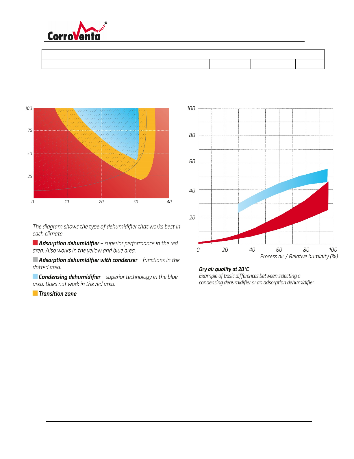
The adsorption principle has the advantage of not having the same temperature dependence as
condensing dehumidification. Adsorption also works way below freezing, whilst condensing drier
capacity decreases sharply with decreasing temperature, which is illustrated in the graph below to the
left.
An adsorption dehumidifier with air-cooled condenser like L4 ES, bridges these properties by working
within a large area, including the primary area of the condensing drier. In other words, it is the best
option for room drying at low temperatures, ideal for emergency damage and construction
dehumidification.
As a general tip when choosing the technique for the relevant drying situation, it can be said that
adsorption dehumidification is the primary choice for drying in unheated spaces or when material drying
is required. The latter is justified by the adsorption dehumidifier producing dehumidifier air, i.e. provides
a greater difference between the incoming and outgoing air's moisture content calculated in grams per
cubic metre (ΔX), which can be seen using the graph to the right below and which is decisive for the rate
of drying. Layered structures are dried by the machine being installed, with the turbine, for suction or
pressure drying.
Page 7
Description:
Manual L4 ES HP; L4 ES HP W
Document Number:
1004289
Created By:
MSHN
Revision Approval Date:
2019-06-28
Revision:
A
© Corroventa Avfuktning AB 6 (42)
Relative humidity (% RH)
Temperature ◦C
Process air / Relative humidity (%)
Dry air / Relative humidity (% RH)
As the graph above shows, condensing drier are used in hot and humid spaces if room drying is required.
Page 8
Description:
Manual L4 ES HP; L4 ES HP W
Document Number:
1004289
Created By:
MSHN
Revision Approval Date:
2019-06-28
Revision:
A
© Corroventa Avfuktning AB 7 (42)
This is how the dehumidifier works
L4 ES is an adsorption dehumidifier with built-in air-cooled condenser through which cooled air from the
surrounding area passes, driven by the process/cooled air fan.
The desiccant used in L4 ES is silica gel, which can be regenerated an almost unlimited number of times.
Silica gel is a crystal with a lot of microscopic pores that make the total surface very large. A single gram
has an active surface of 500 to 700 m2. It is very powerful and can absorb a volume of water of up to
40% of its own weight. It is not water soluble and therefore cannot be washed away or diverted to the
passing air.
Dehumidification process
The desiccant is placed in a rotor (1). The air to be dried is sucked in through the inlet and
passes a filter (2) by means of a process/cooling air fan (3).
The air then passes the drying rotor, after which the dehumidified air goes through the dry air
outlet (4) to the area to be kept dry. The rotor has axially directed air ducts and consists of a
highly active desiccant, silica gel, bonded in a ceramic structure. The axially directed air ducts
in the rotor give laminar flow with minimal pressure drop.
The rotor rotates by means of a drive motor (5) and a drive belt (6). The moisture that
is adsorbed in the rotor is driven out by a small portion of the process air being heated by the
heater (7) and then passing a smaller part of the rotor, which is thus regenerated and cleaned
by the countercurrent principle.
The wet air is removed via the outlet (8) and led to the air-cooled condenser (9), where it is
cooled by air from the surroundings and then resupplied to the dehumidifier as part of the
new process air. The condensation water in the condenser runs down into the bottom tray
(10) and is removed via the built-in pump (11).
The bottom tray is equipped with overfill protection (12) that shuts off the machine if the
condensation water is not removed. The control electronics (13) are located in the cover. L4
ES is also equipped with a cooling air connector (14). The cooling air ensures that the cooling
air flow across the air-cooled condenser and connector connection makes it possible to
connect a cooling air hose to route the cooling air away. If there is a need to create negative
pressure during the drying process, this is an energy efficient way of routing the cooling air
out. The cooling air flow/The cooling air connector must always be fully open.
Page 9
Description:
Manual L4 ES HP; L4 ES HP W
Document Number:
1004289
Created By:
MSHN
Revision Approval Date:
2019-06-28
Revision:
A
© Corroventa Avfuktning AB 8 (42)
11
10
4
7 8 9
2
3 1 6
5
12
13
14
Page 10
Description:
Manual L4 ES HP; L4 ES HP W
Document Number:
1004289
Created By:
MSHN
Revision Approval Date:
2019-06-28
Revision:
A
© Corroventa Avfuktning AB 9 (42)
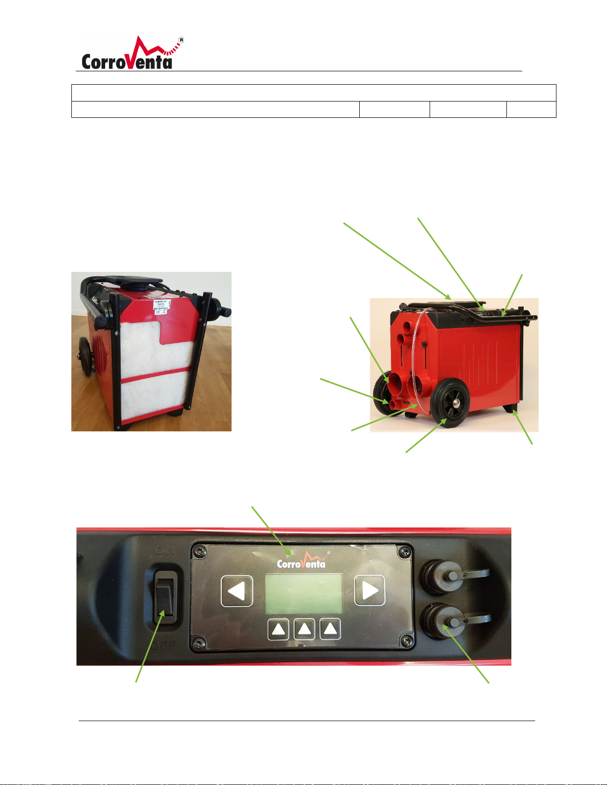
2 x 50 mm
Durable Feet
Switch
Control panel
System
Wheels with roller
HPW)
Product overview
The images below present L4 ES with all external parts and controls.
Folding handle with
integrated cable reel
Dry air outlet with
damper
2 x 100 mm
Cooling air outlet
Control panel
Folding carry
handle/manoeuvring
handle
(only L4 ES HPW)
Process/cooling air inlet
Condensation water
hose
with filter
bearings (only L4 ES
device
Page 11
Description:
Manual L4 ES HP; L4 ES HP W
Document Number:
1004289
Created By:
MSHN
Revision Approval Date:
2019-06-28
Revision:
A
© Corroventa Avfuktning AB 10 (42)
Do not use the machine at temperatures below 0°C as the
Installation
Place L4 ES on a flat and level surface, so that it cannot tip over causing damage to the machine or other
property or injury to people.
L4 ES is very quick and easy to install, which makes it suitable as, for example an emergency machine
that can quickly be on site after damage. It is positioned in the area to be dried in such a way that the
best air circulation is obtained. The better the circulation of the air in the room, the better and faster the
drying. The dehumidifier produces 400 m³ of dry air per hour and because there should be a turnover of
air between 1.5 and 2 times per hour, the machine is suitable for areas with a volume of up to 300 m³.
Do not position the machine closer than 0.5 to 1.0 metres to a wall as this can unnecessarily obstruct
the air flows. Hoses can be connected to the dry air connectors to dry multiple areas simultaneously or
to distribute the dry air further.
If negative pressure is required in the area to be dried, a hose can be connected to the cooling air
connector that is routed out of the area. This air is unheated, thus providing an energy efficient way of
creating negative pressure. Ensure that the Cooling air from the cooling air connector is not blocked.
As with all dehumidification, it is important that L4 ES is used to ensure that the space to be dried is well
enclosed and cordoned off. Any doors and windows to the space must be closed and if there are not
any, use plastic sheeting or another temporary solution. If the space is very small, it is important to
remember that the machine can produce up 1.7 KW of heat, which, depending on the situation, can
quickly lead to a large increase in temperature and thus a decreasing capacity of the machine. Optimum
machine performance is achieved between 0 and 25°C.
When drying wood or in other situations where there is a risk of drying occurring too quickly or at too
low relative humidity, L4 ES can be used with the built-in hygrostat or with an external hygrostat, which
is available as an accessory. Using the hygrostat, you set a threshold value for the relative humidity of
the air at which the machine will switch off and stop dehumidification. If the humidity in the room rises
again, the machine starts automatically.
The machine's condensation water hose is routed to a sewer, floor drain, sink, toilet or similar. The builtin pump can push the water up to five metres in height, which allows the drain to be higher than the
machine.
condensation water can then freeze and damage the built-in pump.
Page 12
Description:
Manual L4 ES HP; L4 ES HP W
Document Number:
1004289
Created By:
MSHN
Revision Approval Date:
2019-06-28
Revision:
A
© Corroventa Avfuktning AB 11 (42)
• Operating range humidity: 20-100% RH
• Operating range temperature: +0°C to +30°C
• The dehumidifier must reach ambient temperature before starting, if stored in cold conditions.
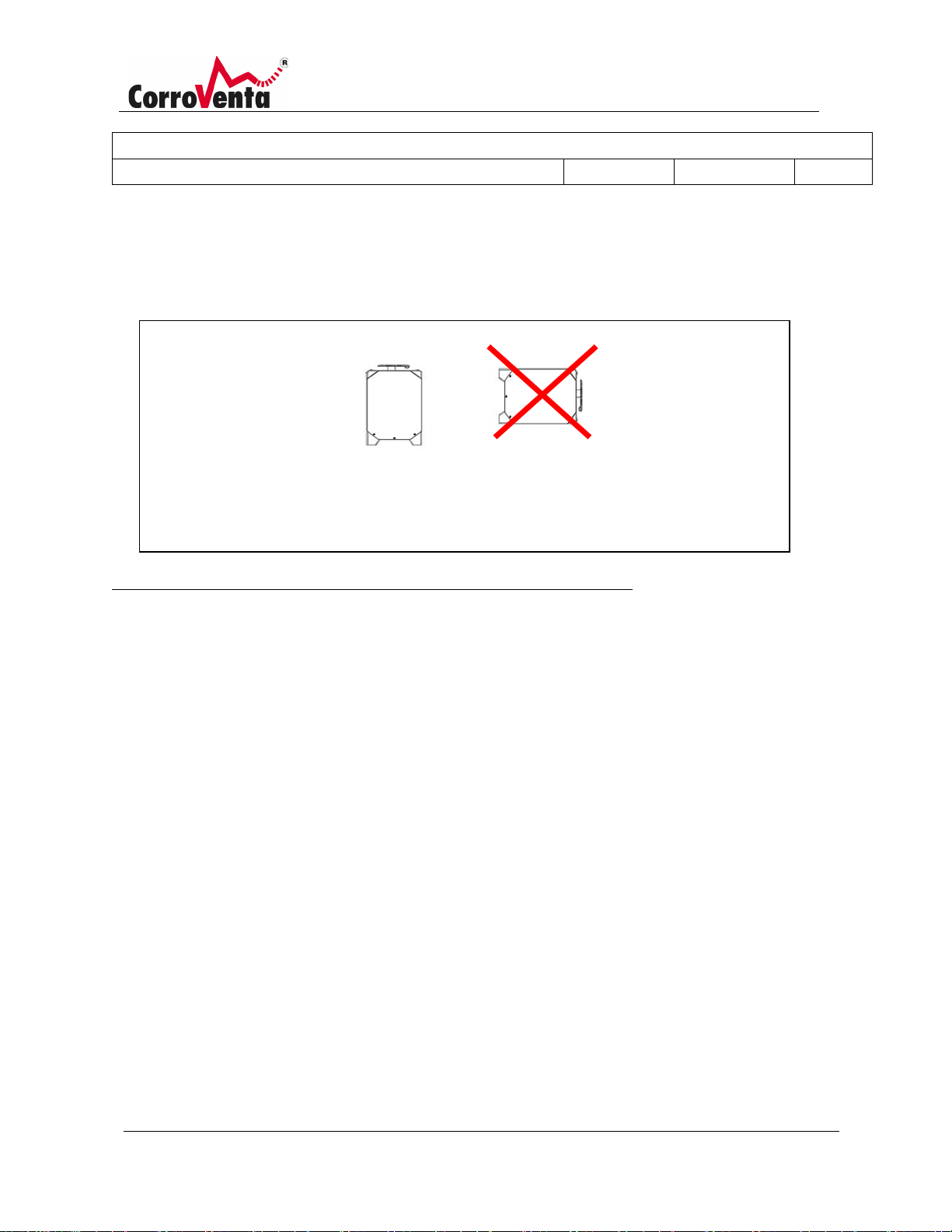
The machine must be transported upright and must always be upright during operation.
Installation in brief (also see page 10, Overview, controls and connections):
• Place the dehumidifier in the area that is to be dried in such a way that good air circulation is
achieved.
• Do not position the machine closer to a wall than 0.5 to 1.0 metres, as this can unnecessarily
obstruct the air flows.
• If needed, use hoses to the dry air connectors to distribute the air.
• Ensure that the dehumidifier is on firm and level ground so that it cannot tip over.
• Route the condensation water hose to a suitable drain. The pump module can achieve a rise of
up to five metres. Ensure that the hose is not pinched and that it is clear, so that the water can
flow unrestricted
• Connect the cable to 1-phase, 230 VAC electrical socket fused to 10A or maximum 16A. Since
the machine is normally used in humid or wet areas, it is strongly recommended to use an earth
fault breaker.
• Start the machine with the switch. When the display lights up and shows the first screen image
after start-up, press Start or Resume.
• When drying wood, or in other situations where drying must not occur too quickly or to too low
a relative humidity, drying should not occur continuously, control mode (MAN-manual position)
should not be selected.
• Before leaving the dehumidifier, check, by looking into the dry air connectors, that the rotor is
rotating, feel for air blowing out of both the dry air connectors and out of the cooling air
connector and that the dry air feels warmer than the surroundings. Check the latter in the upper
connectors closest to the heat cover on the rotor insert. Note that when using a hygrostat, the
Page 13
Description:
Manual L4 ES HP; L4 ES HP W
Document Number:
1004289
Created By:
MSHN
Revision Approval Date:
2019-06-28
Revision:
A
© Corroventa Avfuktning AB 12 (42)
setpoint value may need to be lowered for a while for dehumidification to start – otherwise the
heater and rotor will not run, and the air will not be hot.
Regardless of the area of use, ensure that not all dry air connectors are closed at the same time and
that the cooling air connectors are not blocked.
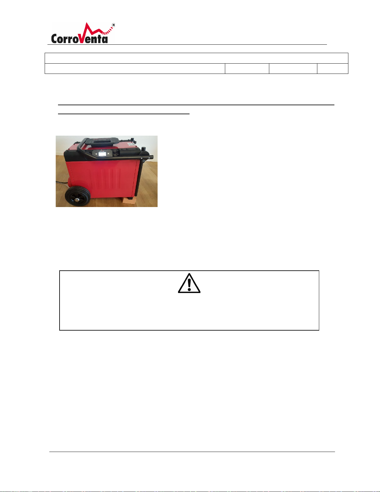
When the work is to be completed, in order to avoid spilling
condensation water on the floor or in the transport vehicle,
the remaining condensation water from the condenser
should be pumped out. Leave the switch in the ON position
and stop the machine by pressing the ”Stop” on the control
panel. The machine then runs in a post cooling mode, the fan
and pump continue to run for 120 seconds before the
machine switches off. The machine can be tilted as illustrated
advantageously.
The machine must be transported upright and must always be upright during operation.
Page 14
Description:
Manual L4 ES HP; L4 ES HP W
Document Number:
1004289
Created By:
MSHN
Revision Approval Date:
2019-06-28
Revision:
A
© Corroventa Avfuktning AB 13 (42)
Transportation
Secure the dehumidifier well when it is being transported.
If the machine toppled over during transportation, the machine must stand upright for at least 30
minutes prior to starting
.
Storage
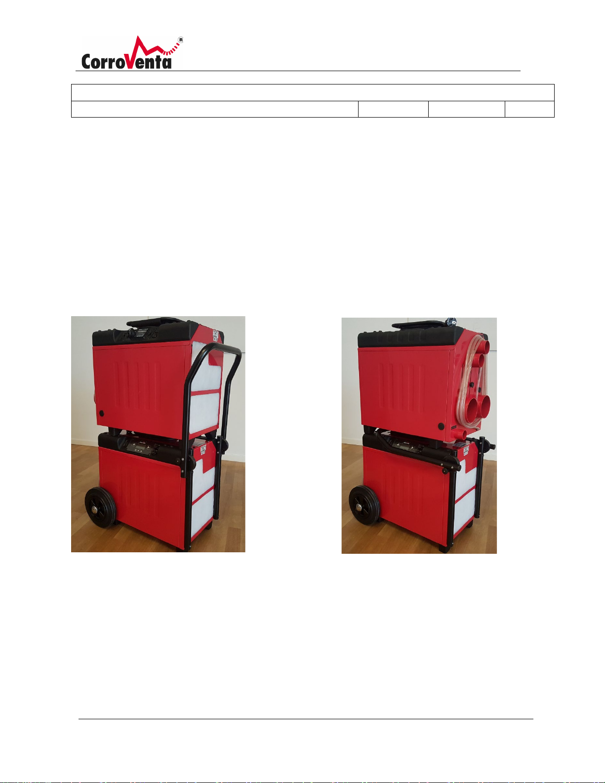
L4 ES can be stored stacked on top of each other as shown below, thus saving floor space. The machine
must always be stored upright and in a frost-free area
.
Page 15
Description:
Manual L4 ES HP; L4 ES HP W
Document Number:
1004289
Created By:
MSHN
Revision Approval Date:
2019-06-28
Revision:
A
© Corroventa Avfuktning AB 14 (42)
C
REDUCE ENERGY CONSUM
Drying methods
The following outlines the basics of different drying methods that can be applied to L4 ES and, in some
cases, additional equipment from Corroventa's product range. The descriptions are only an overview,
and in the event of any doubt about how any given situation should be handled please consult an
experienced dehumidification technician.
General drying, room dehumidification
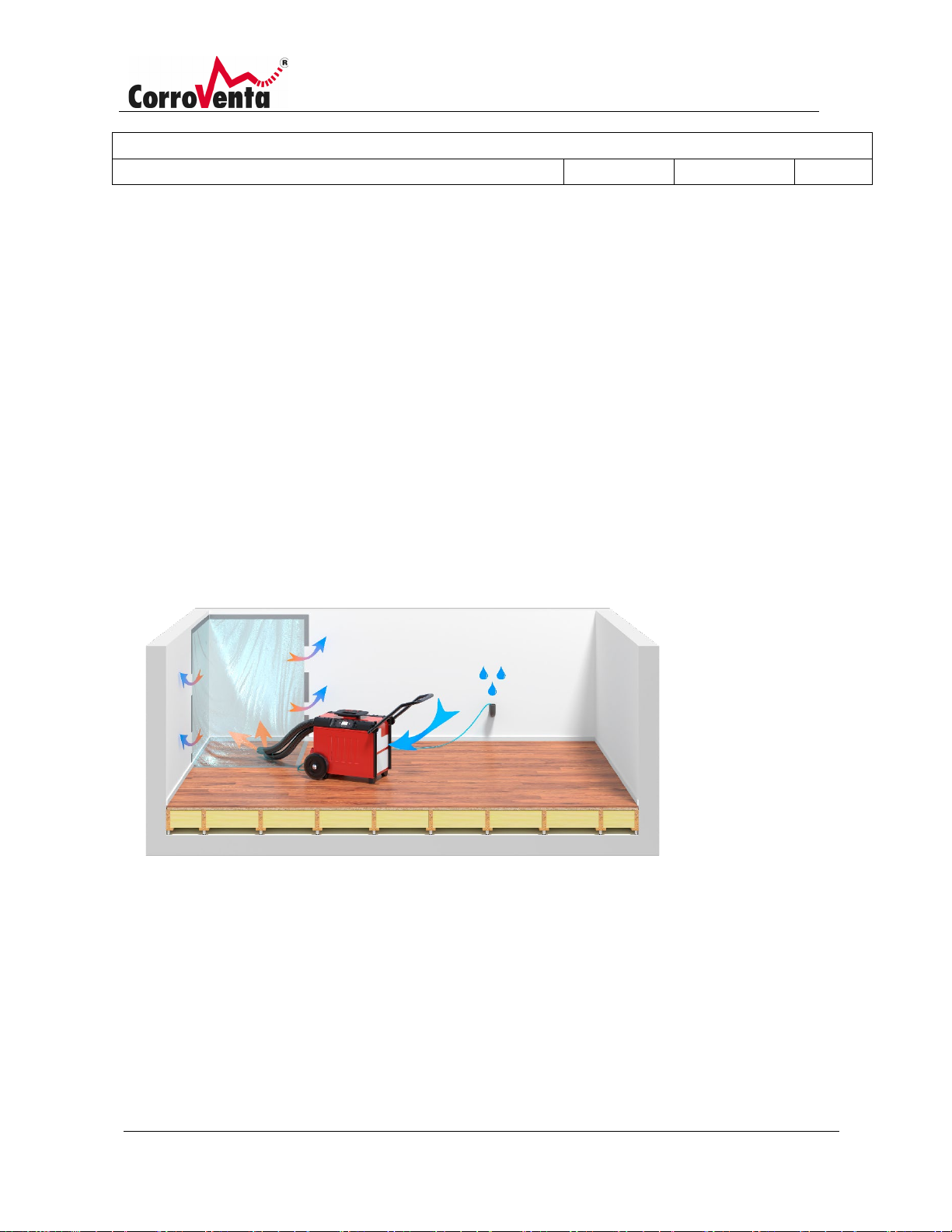
As with all dehumidification, regardless of type or model, it is important to ensure that the area to be
dehumidified is well sealed so that the process is performed as fast and as energy efficiently as possible.
Windows and doors to the area must be closed, and if there are not any, plastic or other temporary
partitions must be used.
If the extent of the damage is limited. it is advisable to cover it with plastic and let the dry air flow in
under the plastic via a hose. Leave openings at the edges where the air can exit. This makes the process
faster and consumes less energy
.
OVER LOCAL DAMAGE WITH PLASTIC WHEN DRYING TO INCREASE THE DRYING RATE AND
PTION.
Page 16
Description:
Manual L4 ES HP; L4 ES HP W
Document Number:
1004289
Created By:
MSHN
Revision Approval Date:
2019-06-28
Revision:
A
© Corroventa Avfuktning AB 15 (42)
D
DIRECTLY CONNECTED T
THE
FAN
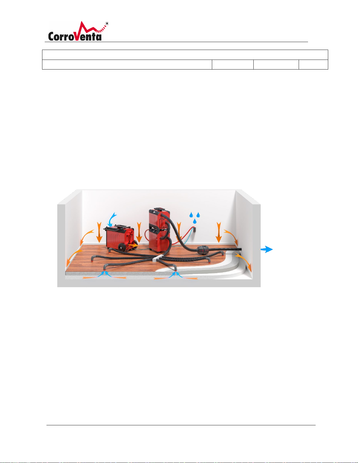
Drying framed flooring and beams
For framed flooring and beams with easy-to-dry insulation, for example, glass wool, L4 ES can be used
with a high-pressure fan such as HP2000 according to the schematic diagram below. Remember that the
capacity of this fan far exceeds that of the dehumidifier and therefore allow the fan to "draw the bad
air". The diagram below shows this by the dry air hose from the dehumidifier to the right not being
connected directly to the fan, but placed next to it instead. In this way, the fan can draw enough air
without drawing excess air through the dehumidifier affecting its function and efficiency
.
RYING BEAMS USING A FAN. NOTE THAT THE DEHUMIDIFIER TO THE RIGHT IS NOT
.
O THE FAN. THE DRY AIR HOSE IS ONLY PLACED CLOSE TO
Page 17
Description:
Manual L4 ES HP; L4 ES HP W
Document Number:
1004289
Created By:
MSHN
Revision Approval Date:
2019-06-28
Revision:
A
© Corroventa Avfuktning AB 16 (42)
S
OUT OF THE LAYERED S
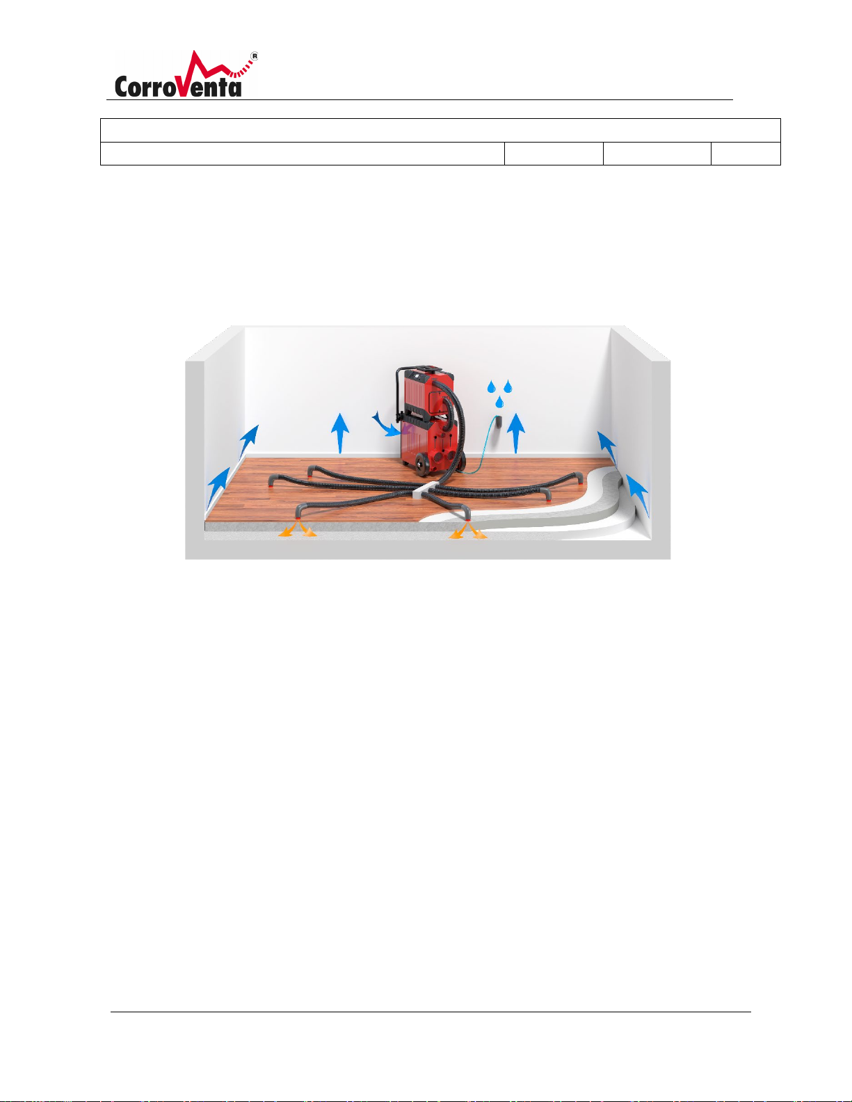
Suction drying
When suction drying layered structures, use L4 ES together with a turbine according to the schematic
diagram below. Connect the turbine or turbines so that they draw air out of the layered structure via
hose system, water separator and filter, and then evacuate the air via the hose out to the surroundings.
Place the dehumidifier in the room and route its condensation water hose out of the room normally. In
this way, the turbine will draw in dry air into the layered structure and this is how the method got its
name.
Use of a water separator is crucial to prevent water being sucked into the turbine and damaging the
motor.
UCTION DRYING. THE DEHUMIDIFIER DRIES THE AIR IN THE SPACE AND THE TURBINES DRAW AIR
TRUCTURE, RESULTING IN DRY AIR BEING DRAWN DOWN INTO IT.
Page 18
Description:
Manual L4 ES HP; L4 ES HP W
Document Number:
1004289
Created By:
MSHN
Revision Approval Date:
2019-06-28
Revision:
A
© Corroventa Avfuktning AB 17 (42)
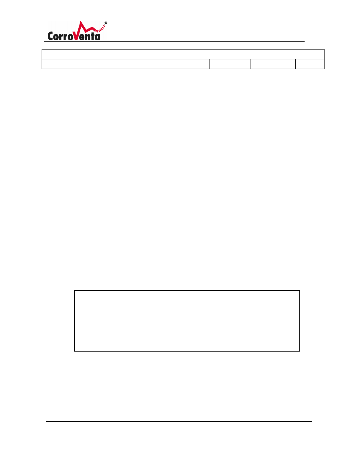
Pressure drying
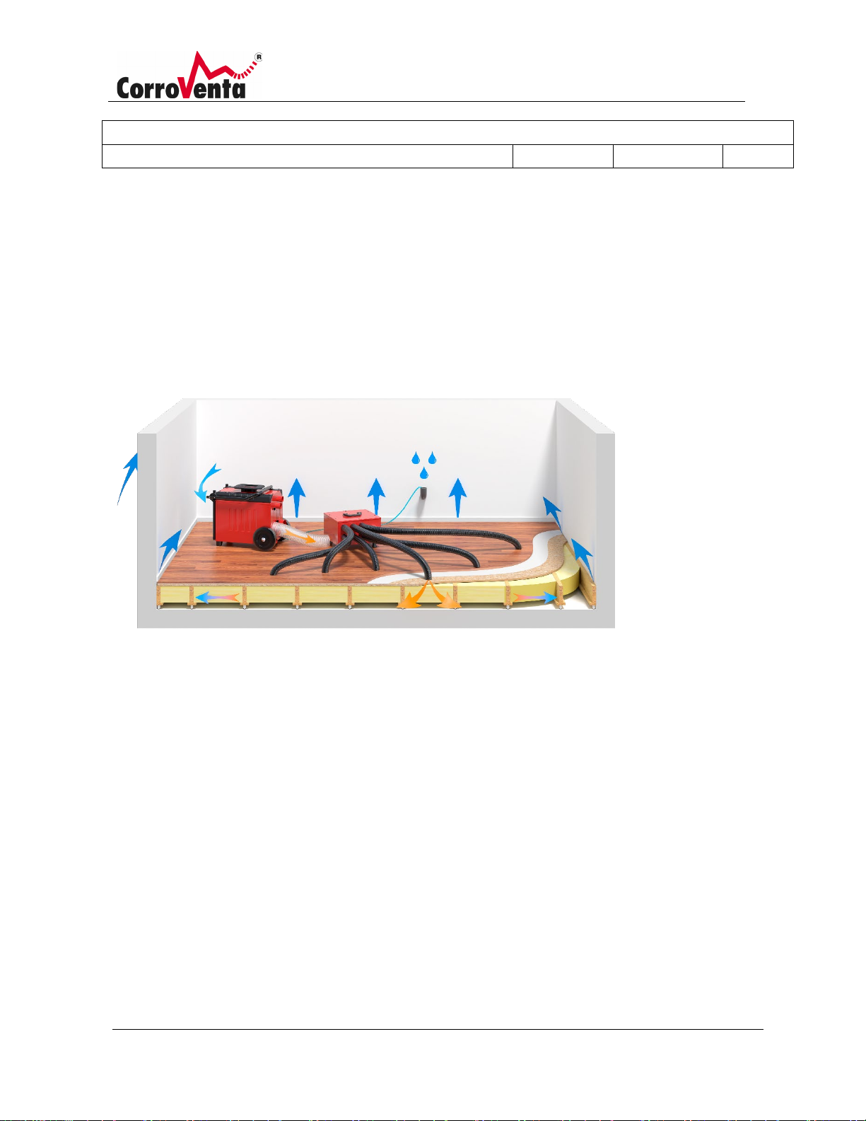
When pressure drying, use L4 ES together with a turbine according to the schematic diagram below.
Pressure drying is two to four times faster than suction drying and is therefore the primary choice for a
layered structure, if there are no obstructions.
PRESSURE DRYING. THE TURBINE IS FED WITH DRY AIR FROM THE DEHUMIDIFIER AND FORCES
IT INTO THE LAYERED STRUCTURE.
During pressure drying, dry air is routed from L4 ES to a turbine and then forces this air into the layered
structure. In this way, warm and dry is forced down into the structure, which achieves the material
temperature and thus increases the rate of the drying process. Wet and cool air leaks into the room
through the gaps between the floor and the wall or via drilled check holes and is then re-sucked into the
dehumidifier as process air.
Before starting pressure drying, suction drying is required to evacuate all free-flowing water so that this
is not forced into other parts of the structure.
Pressure drying may release fibres/particles from the layered structure into the indoor air and if this is a
potential problem another method should be applied.
Page 19
Description:
Manual L4 ES HP; L4 ES HP W
Document Number:
1004289
Created By:
MSHN
Revision Approval Date:
2019-06-28
Revision:
A
© Corroventa Avfuktning AB 18 (42)
Upper buttons to the left and right – Only menu navigation. Never change
Using L4 ES, menus and operation
L4 ES has an easy-to-use user interface with a display and five buttons. The two larger buttons on each
side of the display are used to select between different menus. These buttons are only intended for
navigation and cannot be used to change the settings.
The three smaller buttons are used for selection and editing, and their functions are always presented as
text at the bottom of the screen. On the upper menus, the left-hand button is called the HOME button.
One push of this button takes you straight back to the standard view. In many of the views there is an
Info button that presents information that can be useful for inexperienced users.
If the display's background lighting goes out after the preset time, the first button push only illuminates
the display.
If no button is pushed for ten minutes, a keylock is activated. The machine then must be unlocked by
pushing the two upper button simultaneously. This procedure is presented as text and as an image on
the display.
any settings.
Home button Return to standard view.
Info button Presents information.
Electronic user instructions.
Page 20
Description:
Manual L4 ES HP; L4 ES HP W
Document Number:
1004289
Created By:
MSHN
Revision Approval Date:
2019-06-28
Revision:
A
© Corroventa Avfuktning AB 19 (42)
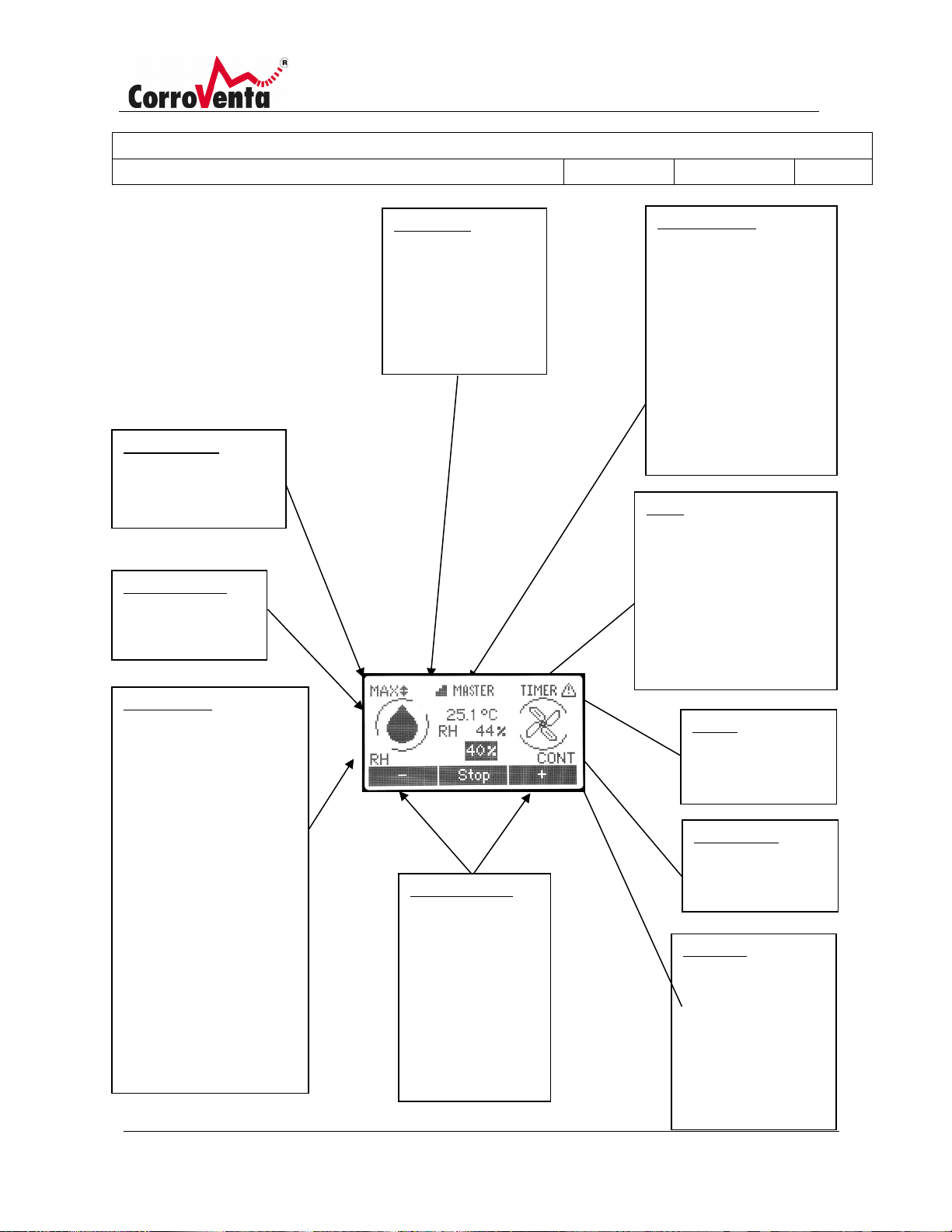
Capacity mode
Eco or ΔX.
SuperVision
Network status
Timer
by another machine.
Alarms
Drying indicator
is in progress.
Fan indicator
is running.
Fan mode
Control mode
Setting setpoint
black background.
Indicates the selected
capacity mode, Max,
Moves when drying
Appears when the
machine is connected
to Supervision for
remote monitoring
and remote control.
”Master” or ”slave”
If the machine is
connected to a local
network this mode is
indicated if the machine
controls the network
(Master), or if it is
controlled by another
machine and thus is Slave.
Indicates when the
machine is set to timer
mode.
Slave – indicates that the
machine is being controlled
Indicates how drying is
controlled, if it is
continuous (MAN =
manual) or if it works to a
preset setpoint for Relative
Humidity (RH), Mixing ratio
(X), or dew point (DP). It
can also be controlled from
an external hygrostat
(HYG).
If an external sensor for
relative humidity and
temperature is used, E.RF,
E.X or E.DP appears in this
mode.
The left and right
buttons below the
screen are used to
increase and
decrease the
setpoint that is
shown against a
The machine has
detected a fault.
Moves when the fan
Cont – continuous
fan.
If this information
does not appear, the
fan only runs when
drying is required.
Page 21
Description:
Manual L4 ES HP; L4 ES HP W
Document Number:
1004289
Created By:
MSHN
Revision Approval Date:
2019-06-28
Revision:
A
© Corroventa Avfuktning AB 20 (42)
Start view
Standard view
Standard view graphics.
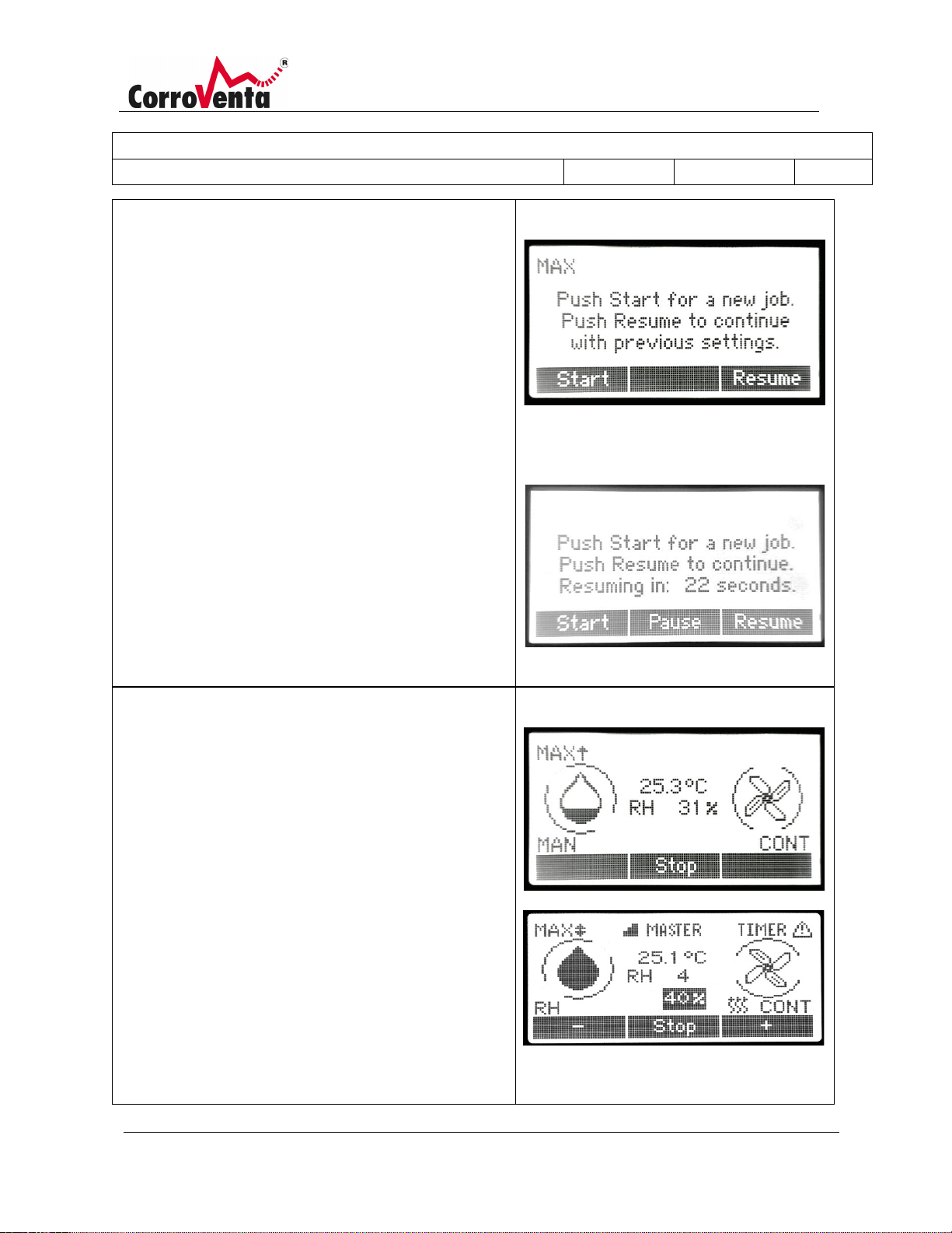
When L4 ES starts up, two options appear for the user on
the display:
Start: Starts the machine with standard settings,
continuous operation with maximum capacity. Previous
settings such as use of sensor control, timer etc.
Resume: The machine resumes operation with the same
settings that previously applied.
If the user did not press the stop button before the power
was interrupted the last time the machine was used, the
machine will automatically resume operation when the
timer has counted down to zero.
The countdown can be stopped by pressing the Stop
button, which then switches the machines to standby
until it is started manually.
Normal start
Start after power cut –
automatic resumption of operation
L4 ES must usually be switched off using the “Stop”
button below the display. The machine then switches to
post cooling mode, the fan and pump run for 120 seconds
before the machine switches off and excess condensation
water is pumped out.
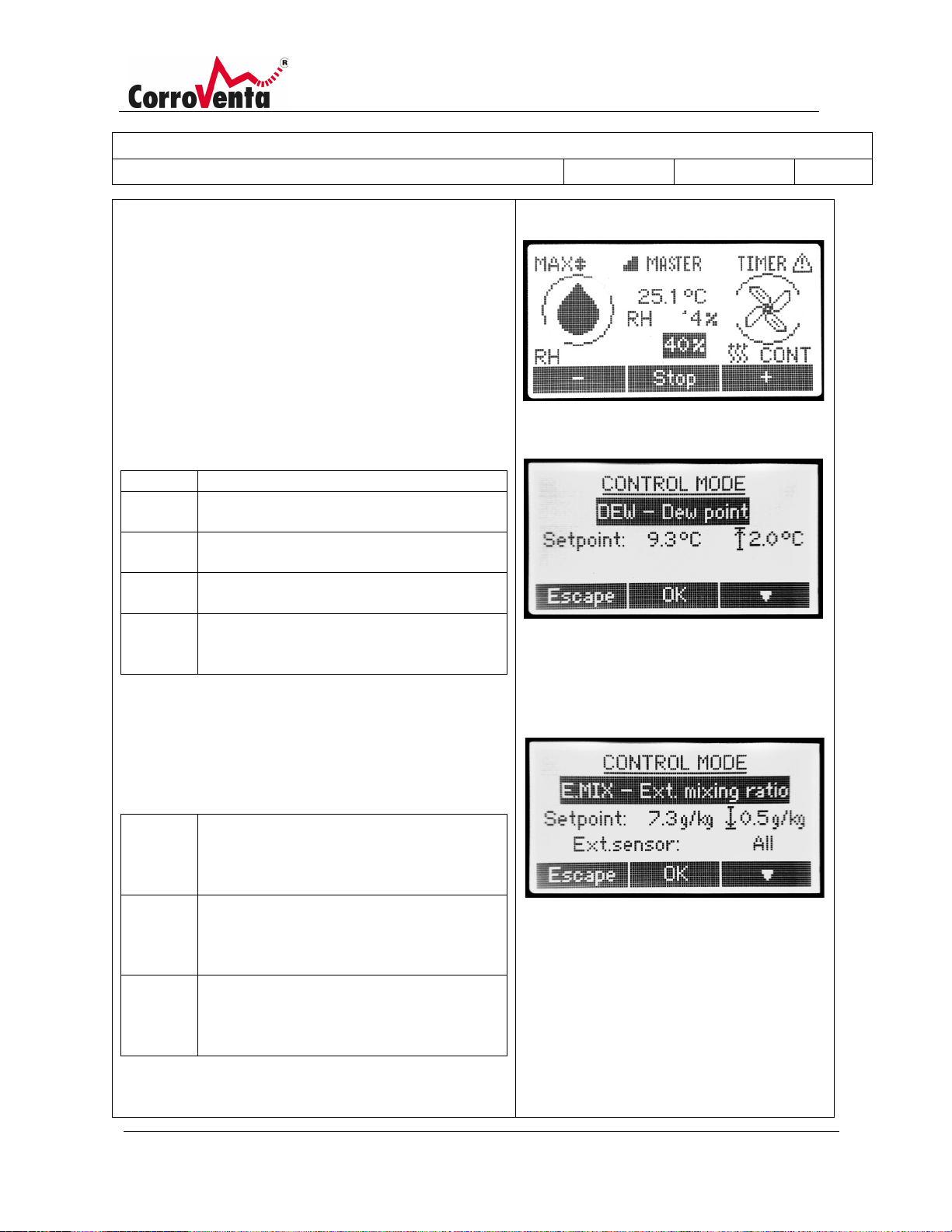
When the machine is running in a control mode instead of
in manual mode, the setpoint (which is marked with black
background in the middle of the screen) can be increased
or decreased using the negative (-) and positive (+)
buttons.
Page 22
Description:
Manual L4 ES HP; L4 ES HP W
Document Number:
1004289
Created By:
MSHN
Revision Approval Date:
2019-06-28
Revision:
A
© Corroventa Avfuktning AB 21 (42)
Control mode
MAN
Manual, continuous drying.
RH
Dehumidification for selectable relative
humidity (%).
X
Dehumidification for selectable mixing ratio
(g/kg).
DP
Dehumidification for selectable dew point
(°C).
HYG
Dehumidification is controlled by an
machine.
E.RH
Dehumidification for selectable relative
that are connected to the machine.
E.X
Dehumidification for selectable mixing ratio
the machine.
E.DP
Dehumidification for selectable dew point
machine.
network connected and connected to an external temp.
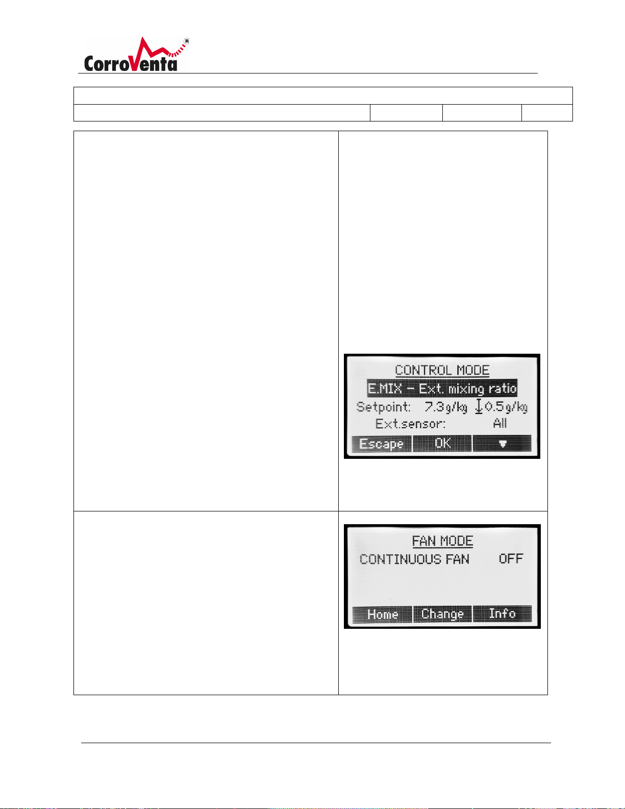
In control mode, it is determined whether drying should
occur continuously (MAN - manual mode) or is only to be
activated when necessary, on the basis of the ambient
climate.
The selected control mode is displayed in the lower, lefthand corner in standard view.
Open the screen for selecting control mode by pressing
the upper, right-hand button.
The following basic control modes are available:
external hygrostat that is connected to the
Thanks to its network functions, you can also connect the
machine to external temp. and RH sensors, and use their
values to control operation, instead of the built-in sensor
for relative humidity and temperature. The following
modes for external sensors exist for this purpose:
humidity (%) according to the input values
from the external temp and RF sensor(s)
(g/kg), according to the input values from
the external sensor(s) that are connected to
(°C), according to the input values from the
external sensor(s) that are connected to the
The external control mode requires that the machine is
Page 23
Description:
Manual L4 ES HP; L4 ES HP W
Document Number:
1004289
Created By:
MSHN
Revision Approval Date:
2019-06-28
Revision:
A
© Corroventa Avfuktning AB 22 (42)
and RH sensor. If the machine is not already connected to
Fan mode
the network, the machine asks whether to create a
network.
If there are several sensors in the network and if the <All<
option has been selected (instead of a single sensor, e.g.
RHT61) the machine works on the "worst case scenario"
and runs for as long as any of the sensors detects that the
humidity is above the setpoint.
If the machine selects a mode other than MAN, the user
will note that the setpoint can be set.
When the setpoint has been reached, drying stops
automatically. If the humidity later rises above the
setpoint again, drying resumes automatically.
Hysteresis
When one of control modes; RH, DP or X is selected, a
symbol and a hysteresis value appears to the right of the
display.
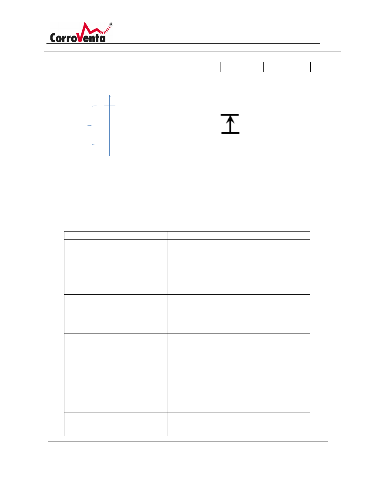
The symbol shows the setpoint value's position in the
operation range as below.
↕ - centre
↓ - bottom
↑ - top
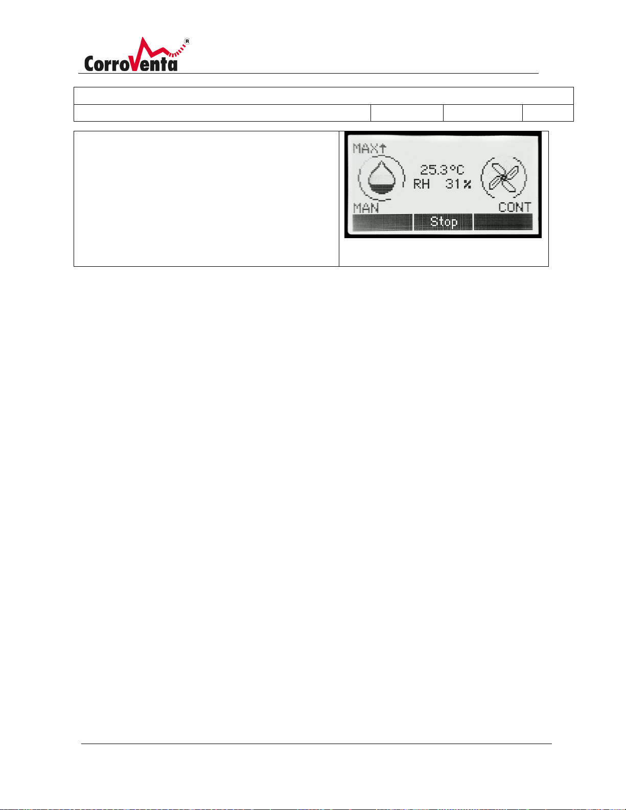
The fan mode determines whether the fan in the
dehumidifier is to work continuously or only for as long as
drying is required.
If continuous fan is selected, the word Cont appears in
the lower right-hand corner in standard view.
For optimal drying effect, continuous fan operation
should be used as far as is possible to keep the air
moving.
Page 24
Description:
Manual L4 ES HP; L4 ES HP W
Document Number:
1004289
Created By:
MSHN
Revision Approval Date:
2019-06-28
Revision:
A
© Corroventa Avfuktning AB 23 (42)
Page 25
Description:
Manual L4 ES HP; L4 ES HP W
Document Number:
1004289
Created By:
MSHN
Revision Approval Date:
2019-06-28
Revision:
A
© Corroventa Avfuktning AB 24 (42)
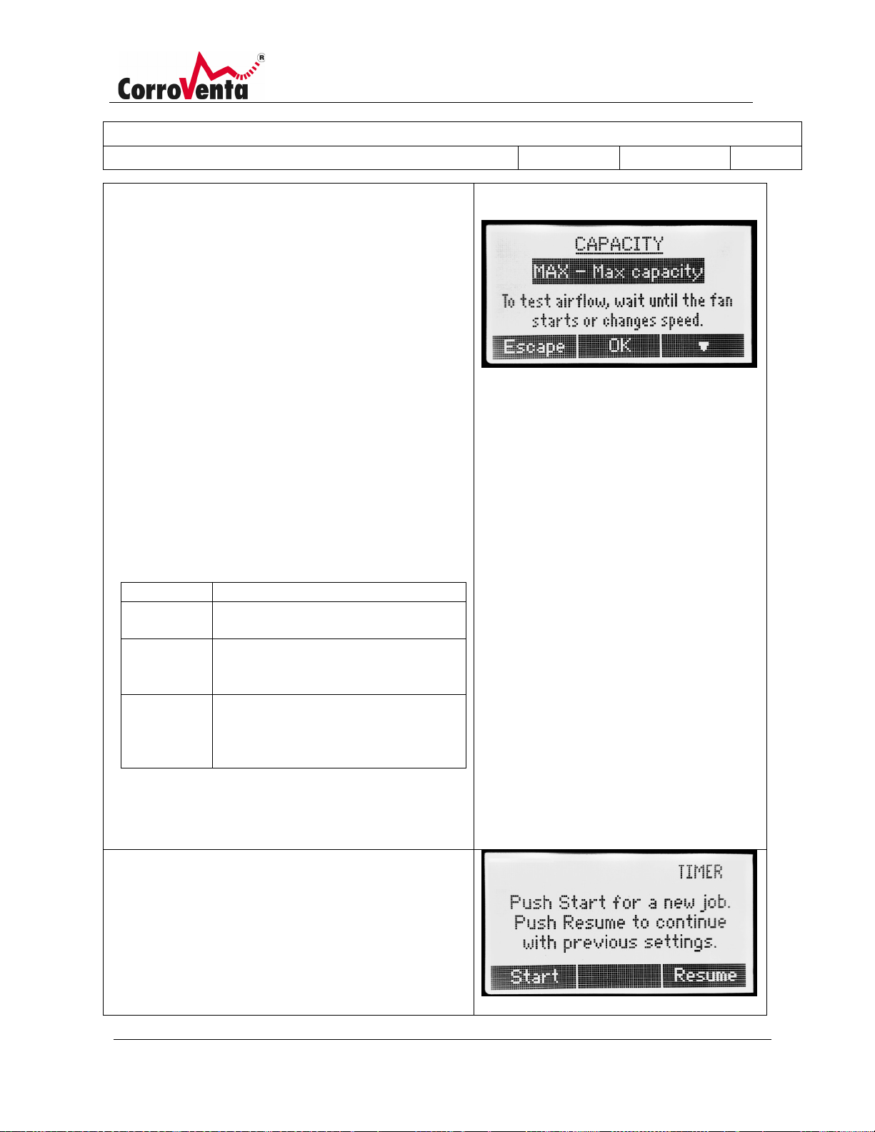
Capacitymode
MAX
For maximum removal of water.
ECO
For minimal energy consumption per
litre of removed water.
ΔX1, ΔX2...
For maximum ΔX, as dry air as
for e.g. local, isolated water damage.
TRT
Pressure drying mode that can be used
turbine.
Timer
The drying capacity of L4 ES can be optimised for a given
work task and situation with three different operating
modes.
When setting MAX (maximum) the machine works to
remove as much water as possible. If the machine's total
power is not required, it can instead be set to ECO (ecomode) where the energy consumption per litre of
removed water is minimised.
For localised water damage where the dry air volume is
not required, the machine can be set to one of its ΔX
modes. In this mode, the machine produces a smaller
amount of even drier air that further accelerates the
drying process. The difference between ΔX1 and ΔX2 etc.
is the dry air volume. ΔX1 has the smallest volume.
For use during pressure drying when the machine is
connected as slave to a turbine in a local network, L4 ES
also has a pressure drying mode (TRT) where it
automatically adjusts the wet air flow so that the
produced air is as dry as possible.
possible. Reduced air amounts suitable
when the machine is connected to a
network and connected as slave to a
L4 ES has an integrated timer function that allows the
user to determine when the machine is to run. When the
timer function is used, the word Timer appears in the
standard view's upper, right-hand corner according to the
graphic to the right.
Page 26
Description:
Manual L4 ES HP; L4 ES HP W
Document Number:
1004289
Created By:
MSHN
Revision Approval Date:
2019-06-28
Revision:
A
© Corroventa Avfuktning AB 25 (42)
Network
master, i.e. control the others.
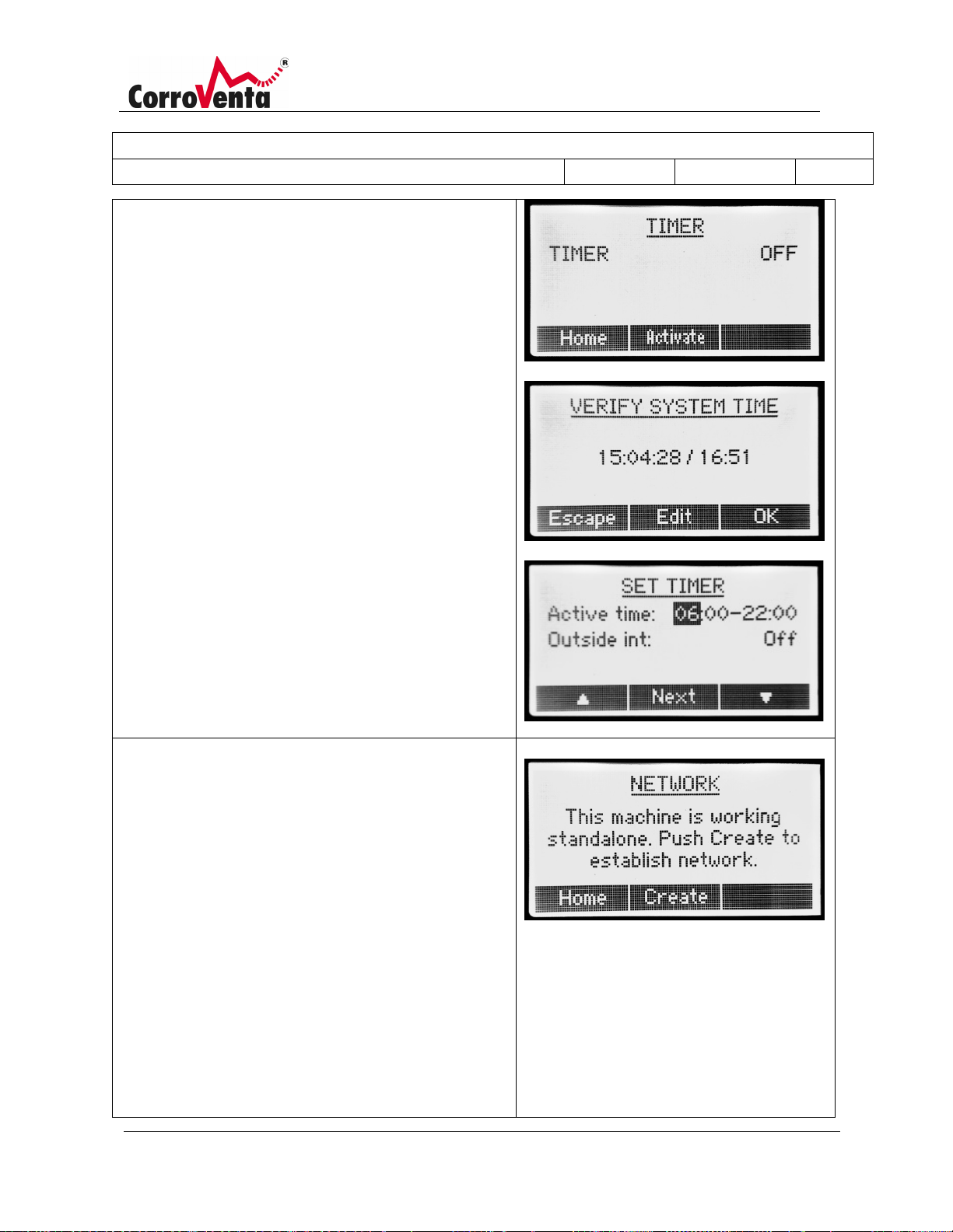
Activate the timer by pressing the right-hand arrow
button four times to open the timer menu.
Press Activate.
When the timer has been activated, the machine begins
by prompting the user to check that the time and date
have been set correctly. If they have been, press OK. If the
time or date need changing, press Edit and adjust the
values before continuing.
In the next step the user can set the time interval that the
machine is to work within. The machine remembers the
timer settings from the previous time it was used and
shows its settings as the start values.
The Other time setting determines whether the machine,
during the day's remaining hours, must be in standby
mode or run at lower fan speed for minimal noise.
Note! Install all system cables before the machines are
started.
L4 ES has network functions that enable local interaction
between machines, for example pressure drying and use
of external sensors for relative humidity and temperature
control of the machine. The network functions also
prepare the machine for a future SuperVision system that
will allow remote monitoring and remote control of the
machines via Internet.
A network is established by installing the machines in the
intended way and connecting them to each other using
system cables before they are started.
Open the network menu on the machine which is to be
Page 27
Description:
Manual L4 ES HP; L4 ES HP W
Document Number:
1004289
Created By:
MSHN
Revision Approval Date:
2019-06-28
Revision:
A
© Corroventa Avfuktning AB 26 (42)
Setup and maintenance menus
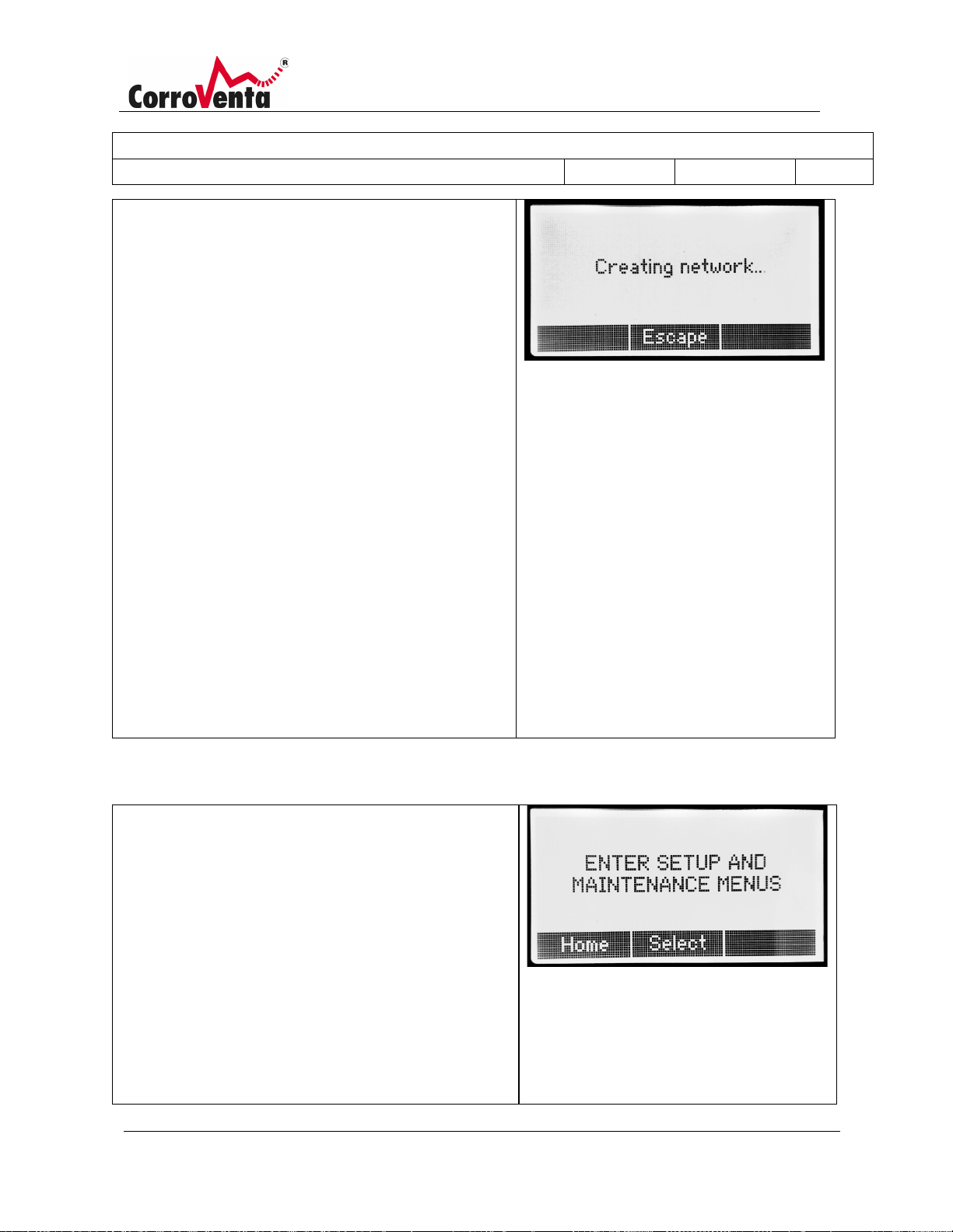
Press Create and wait while the machine establishes the
the master machine is in operation.
network. This can take up to one minute.
Once the network has been established, the display
switches between the slave units in the network menu.
These are indicated by type (e.g. L4 ES) and bus address
(e.g. 101).
To change the settings for a slave unit, press Change and
select the slave unit. The background lighting for the
selected unit starts to flash to confirm that the unit has
been selected.
Desired settings can also be made directly on the relevant
machine.
Start the master machine when all desired settings have
been made. The slaves start automatically within one
minute. The machines are stopped in the same way. Press
stop on the master machine and the slaves stop
automatically shortly afterwards.
As the network is controlled by the master machine, a
slave unit that is started manually is stopped when the
master machine is in standby. In the same way, a slave
unit that is stopped manually is restarted manually when
The setup and maintenance menus contain functions that
are not needed for normal operations.
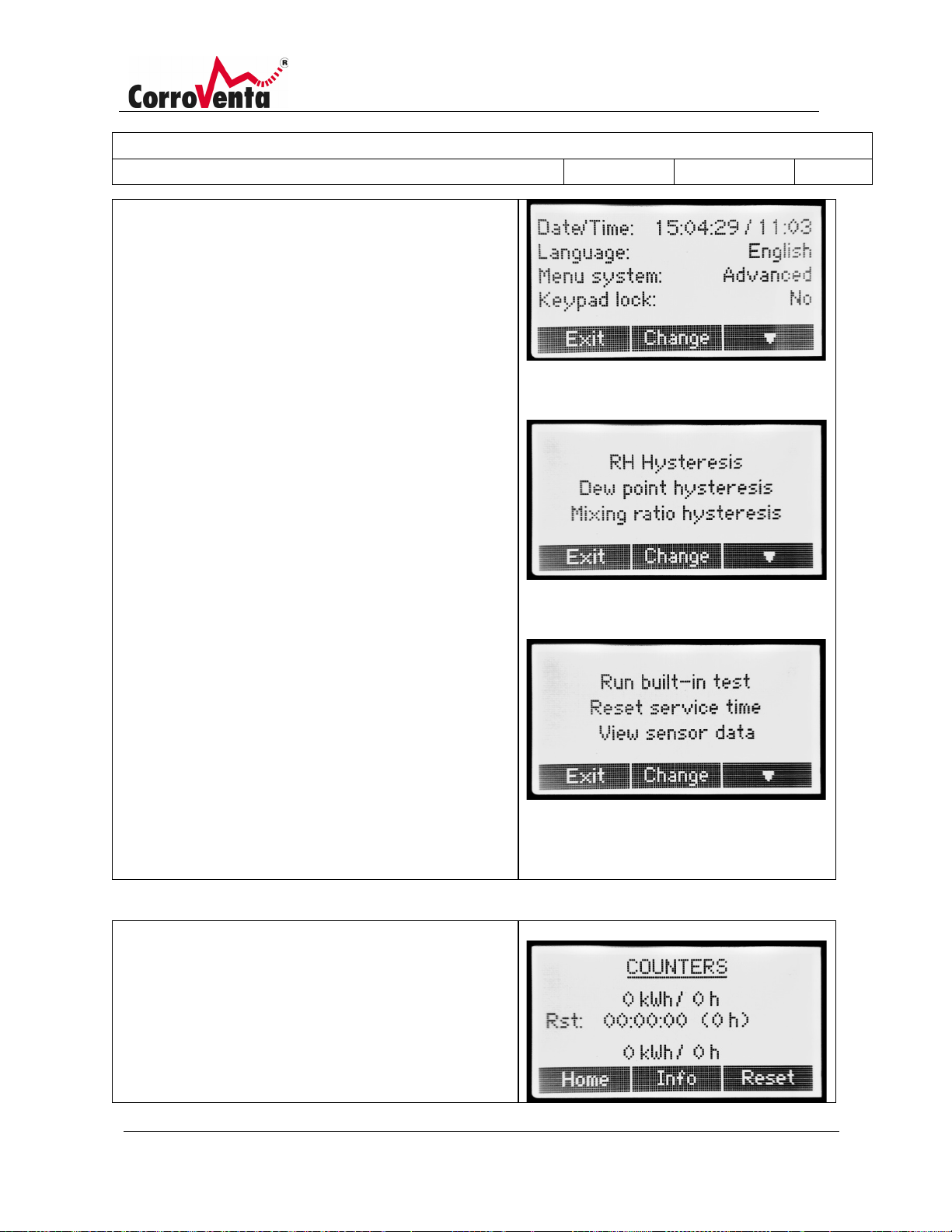
Date and time: Setting system date and system time: The
format is YY:MM:DD / HH:MM.
Language: Language selection for the interface.
Menu system: The menu system is set to Advanced as
standard with all functions visible and available. If it is set
to Basic, the more advanced functions are removed from
the menu system.
Page 28
Description:
Manual L4 ES HP; L4 ES HP W
Document Number:
1004289
Created By:
MSHN
Revision Approval Date:
2019-06-28
Revision:
A
© Corroventa Avfuktning AB 27 (42)
Keylock: Option to activate/deactivate the keylock:
Counters
RH hysteresis: Option to adjust the hysteresis settings for
control mode RH. The setpoint's position in the operation
interval and the hysteresis value can be set from here.
Dew point (DP) hysteresis: Option to adjust the hysteresis
settings for control mode dew point (DP). The setpoint's
position in the operation interval and the hysteresis value
can be set from here.
Mixing ratio (X) hysteresis: Option to adjust the hysteresis
settings for control mode mixing ratio (X). The setpoint's
position in the operation interval and the hysteresis value
can be set from here.
Run built-in test: A built-in self-test that is available to
service technicians.
Reset service time: The machine is set to remind you
about a service once a year. Once the service has been
carried out, the service reminder can be reset using this
function.
See sensor data: Function intended for service
technicians.
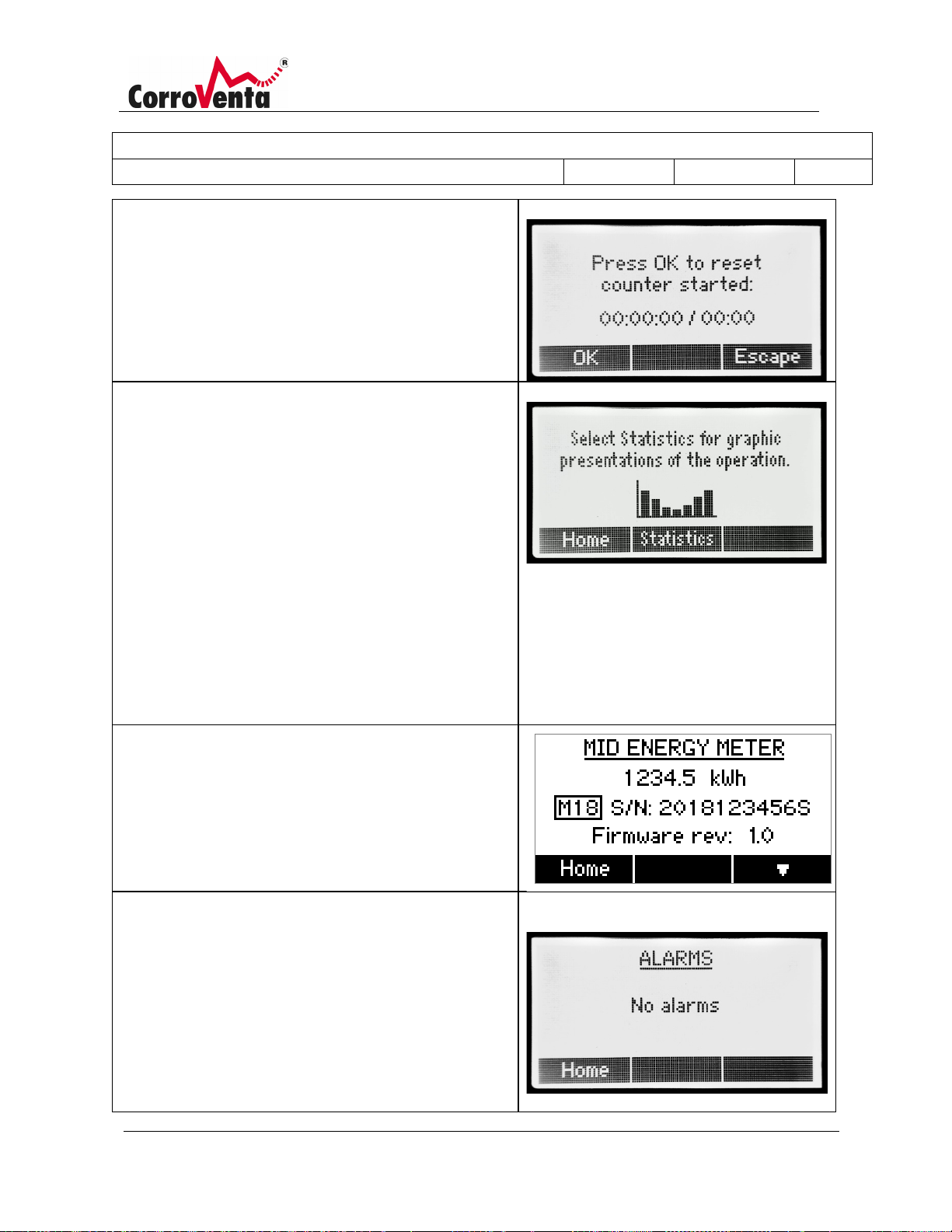
This screen shows time and energy counters.
The resettable work counters are displayed at the top. The
date when the counters were reset is displayed below.
After the date, the number of hours that have passed
since the last reset are indicated to enable a quick
comparison.
Page 29
Description:
Manual L4 ES HP; L4 ES HP W
Document Number:
1004289
Created By:
MSHN
Revision Approval Date:
2019-06-28
Revision:
A
© Corroventa Avfuktning AB 28 (42)
Press Reset to reset the work counters. Confirm to reset
Statistics
graph, is the current hour or the current day.
MID Energy Meter
Alarms
the counters by pressing OK on the following screen.
The counters for energy and hours for the entire service
life of the machine are displayed at the bottom. These
counters cannot be reset.
Statistics are provided to assist the user's observation of
the drying process and to enable the monitoring and
follow-up of machine operation.
The following graphs appear below the statistics menu:
• Average relative humidity for the last twelve
hours and the last 14 days.
• Average temperature for the last twelve hours
and the last 14 days.
• Number of hours in drying mode for the last 14
days.
• Consumed energy in kWh for the last 14 days.
The last value, the bar at the far right in the respective
This menu presents the total, accumulated energy
consumption.
For more information, please refer to chapter MID Energy
Meter.
Identified alarms are shown on this screen. As soon as an
alarm is identified, a pop-up window also appears.
Additionally, a warning symbol appears in the standard
view's upper right corner, as long as the fault remains.
The user does not have to erase the alarms that are
shown. As soon as the machine detects that the function
has been reset, the alarm disappears automatically.
Page 30
Description:
Manual L4 ES HP; L4 ES HP W
Document Number:
1004289
Created By:
MSHN
Revision Approval Date:
2019-06-28
Revision:
A
© Corroventa Avfuktning AB 29 (42)
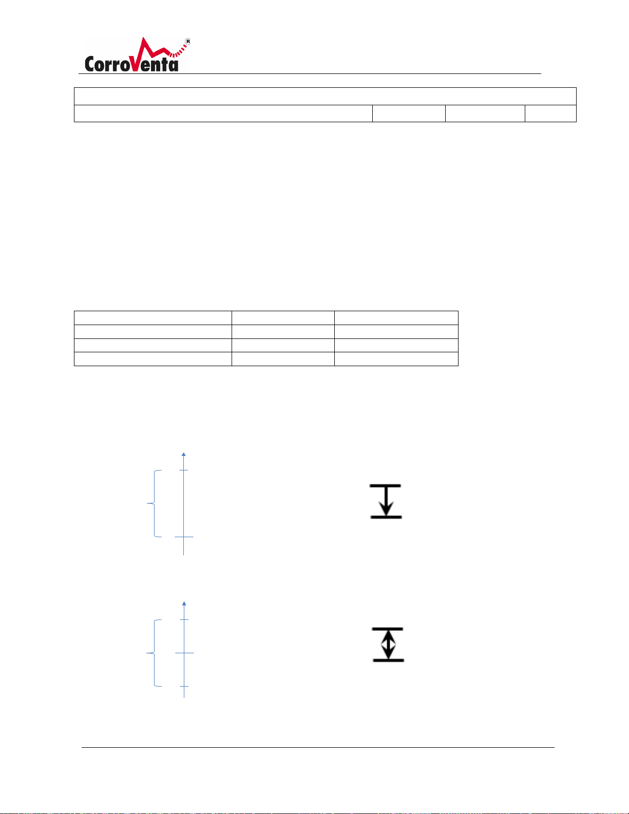
Control mode
Hysteresis
Setpoint's position
RH
4 %
Bottom
Dew point
2°C
Top
Mixing ratio
0.5 g/kg
Bottom
Setpoint RH 60 %
Start drying = 65 %
Hysteresis
5 %
Bottom
Setpoint RH 60 %
Start drying = 62.5 %
Stop drying = 57.5 %
Hysteresis
5 %
Centre
Control mode and hysteresis
In addition to the normal, continuous drying operation, the operation of L4 ES can also be controlled via
its built-in sensors for relative humidity and temperature as well as via its external hygrostat or external,
networked sensor.
If a built-in or external electronic sensor is used, the machine uses a software-controlled hysteresis that
stabilizes machine operation and prevents too many restarts.
The table below shows the machine's standard settings. If changes are required, these can be made in
the setup and maintenance menus.
The illustrations below describe the different hysteresis settings; bottom, center and top
.
Page 31
Description:
Manual L4 ES HP; L4 ES HP W
Document Number:
1004289
Created By:
MSHN
Revision Approval Date:
2019-06-28
Revision:
A
© Corroventa Avfuktning AB 30 (42)
Alarms
Action/advice
On or more slaves not responding
This alarm appears when the machine is used as
again.
Ambient temperature too high!
The machine has switched off all heaters due to too
automatically if the temperature drops.
Fan control error
The fan speed deviates from the expected fan
technician.
No contact with internal control
board
Internal fault. If the alarm remains, contact a
service technician.
Internal sensor fault Temp and RH
Internal fault. If the alarm appears after the
remains, contact a service technician.
External Temp and RF sensor fault
The machine has lost contact with the external
correctly installed. When contact with the external
Setpoint RH 60 %, start drying
Hysteresis
5 %
Stop drying = RH 55 %
Top
Alarms
If the machine detects a fault, corresponding information appears in a pop-up window. Additionally, a
warning symbol appears in the standard view's upper right corner, if one or more problems remain.
The following alarms can appear. Recommended corrective action is also given for each alarm.
master in a network that has lost contact with one
or more of its slave machines. If this alarm appears,
check all system cables and the power supply to all
machines. When communication has been reestablished, the alarm disappears automatically
high ambient temperature (above 35 degrees
Celsius). If continuous fan is selected, the fan
continues to run. The machine resumes operation
speed. If the alarm remains, contact a service
sensor
machine has been disassembled, the fault may be
because the sensor connection to the cover has not
been installed correctly. If not, and if the alarm
temp and RH sensor(s). Check that the cables are
Page 32
Description:
Manual L4 ES HP; L4 ES HP W
Document Number:
1004289
Created By:
MSHN
Revision Approval Date:
2019-06-28
Revision:
A
© Corroventa Avfuktning AB 31 (42)
sensors has been lost, the machine automatically
returns to using the built-in temp and RF sensor.
The statistics cannot be saved to the
memory
Internal fault. If the alarm remains, contact a
service technician.
The event log cannot be saved to the
memory
Internal fault. If the alarm remains, contact a
service technician.
Water level
The bottom tray is filled with condensation water.
pressure build up.
Check that the condensation hose is not blocked.
Check that the pump runs by holding the outlets on
the condensation water hose and feel for a small
Page 33
Description:
Manual L4 ES HP; L4 ES HP W
Document Number:
1004289
Created By:
MSHN
Revision Approval Date:
2019-06-28
Revision:
A
© Corroventa Avfuktning AB 32 (42)
MID ENERGY METER MENU
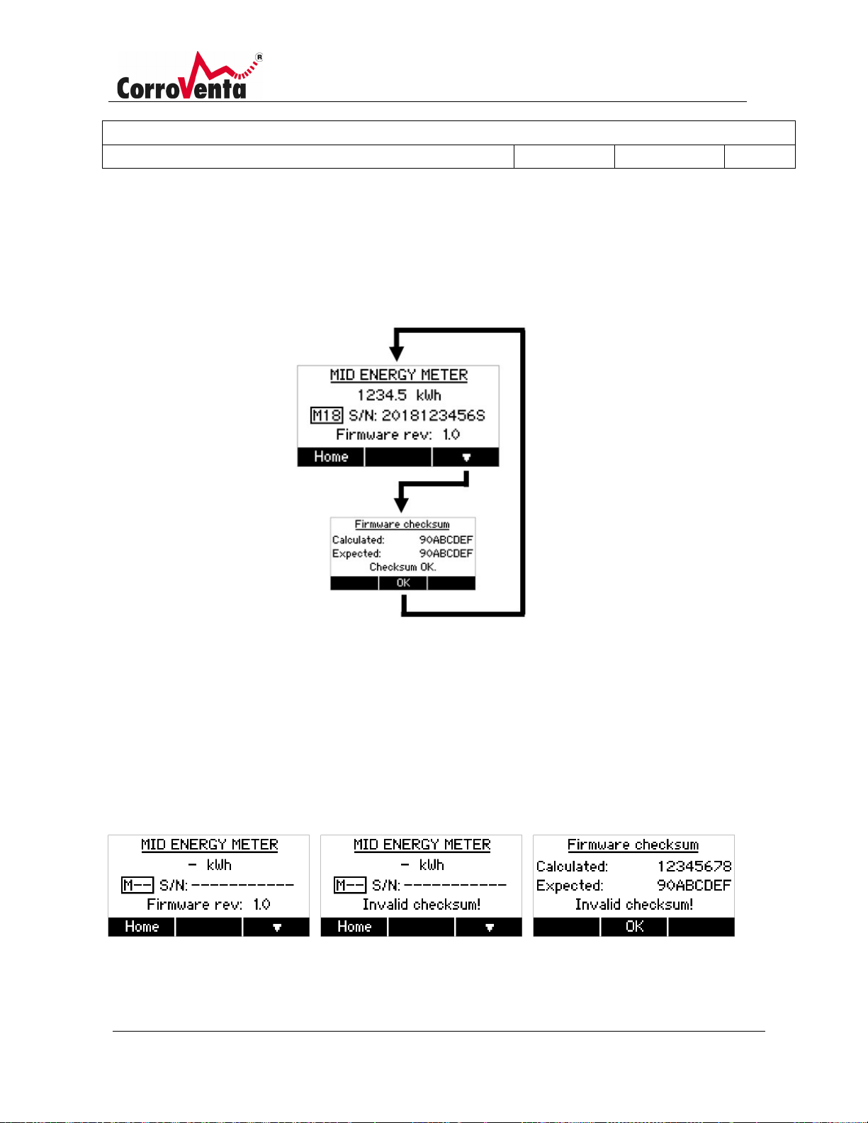
Part of the main menu loop and accessible with either of the navigation keys, the MID Energy Meter menu
presents the total, accumulated energy consumption. The affixing, M18 in the example below, as well as the
serial number that follows is information on the built-in CEMP energy meter. The revision number given at
the bottom row refers to the legally relevant firmware within the machine.
The integrity of the data presented with this menu is thoroughly checked and protected. One such important
test is the calculation of a checksum to verify that the program memory has not been corrupted. The result of
the latest calculation is always available with the Firmware checksum screen, accessed through the MID
Energy Meter menu with the lower right button. If any of the tests fail and the machine concludes that the
available energy meter data must not be trusted, the information is removed from the screen and replaced
with dashes. If the problem detected has to do with the checksum calculation, the bottom row of the screen
will say so.
Left: Data removed due to communication error
Centre: Data removed due to checksum error
Right: Appearance of Firmware checksum screen when error is detected.
Page 34
Description:
Manual L4 ES HP; L4 ES HP W
Document Number:
1004289
Created By:
MSHN
Revision Approval Date:
2019-06-28
Revision:
A
© Corroventa Avfuktning AB 33 (42)
Network functions
As a member of the new product family CTR ES, L4 ES can be included in a network together with other
turbines and adsorption dehumidifiers with several functions, such as for example
• Relation – interaction between two or more turbines with a defined relationship between
respective air flows.
• Optimised pressure drying, an operating method where the slave connected adsorption
dehumidifier automatically adjusts to the turbine's airflow and thus produces as dry air as
possible.
• Operation with common timer.
• Interaction with the future SuperVision system that enables remote monitoring and remote
control of machine operation.
For network connected machines, no pre-configuration or other preparation is required. Once the
machines have been installed, they can be connected easily using system cables. All that is then required
is a single press of the Create button in the network menu on the machine that will be master. The
master is the machine that is designated to control other machines. All machines can be used for this
purpose. When operating modes Relation and Pressure drying are to be used, the master machine must
be a turbine. For all other purposes, it does not matter which machine is master in the network.
The settings can be changed directly on the machine that is connected as a slave to another unit, and
not only via the master machine. If the user selects to make necessary changes via the master machine,
the display flashes on the selected slave machine for as long as the changes are being made. Thus
avoiding confusion in that the machine can be easily identified.
Connecting machines to a network
Carry out the following when connecting machines to a network, e.g. in order to use the dehumidifier's
pressure drying operation:
1. If the machines are connected, switch them off. Then connect the machines to each other using
system cables. The two connectors on the machines have the same function, so it does not
matter which of them is used. If SuperVision is to be used, it can be connected to any machine.
2. Start the machines.
3. Select which machine is to be master. During pressure drying, the master machine must be the
turbine, which is used to force dry air into the construction.
If the units are used in a network with the single purpose of monitoring and remotely controlling
them via SuperVision, it does not matter which machine is master.
Page 35
Description:
Manual L4 ES HP; L4 ES HP W
Document Number:
1004289
Created By:
MSHN
Revision Approval Date:
2019-06-28
Revision:
A
© Corroventa Avfuktning AB 34 (42)
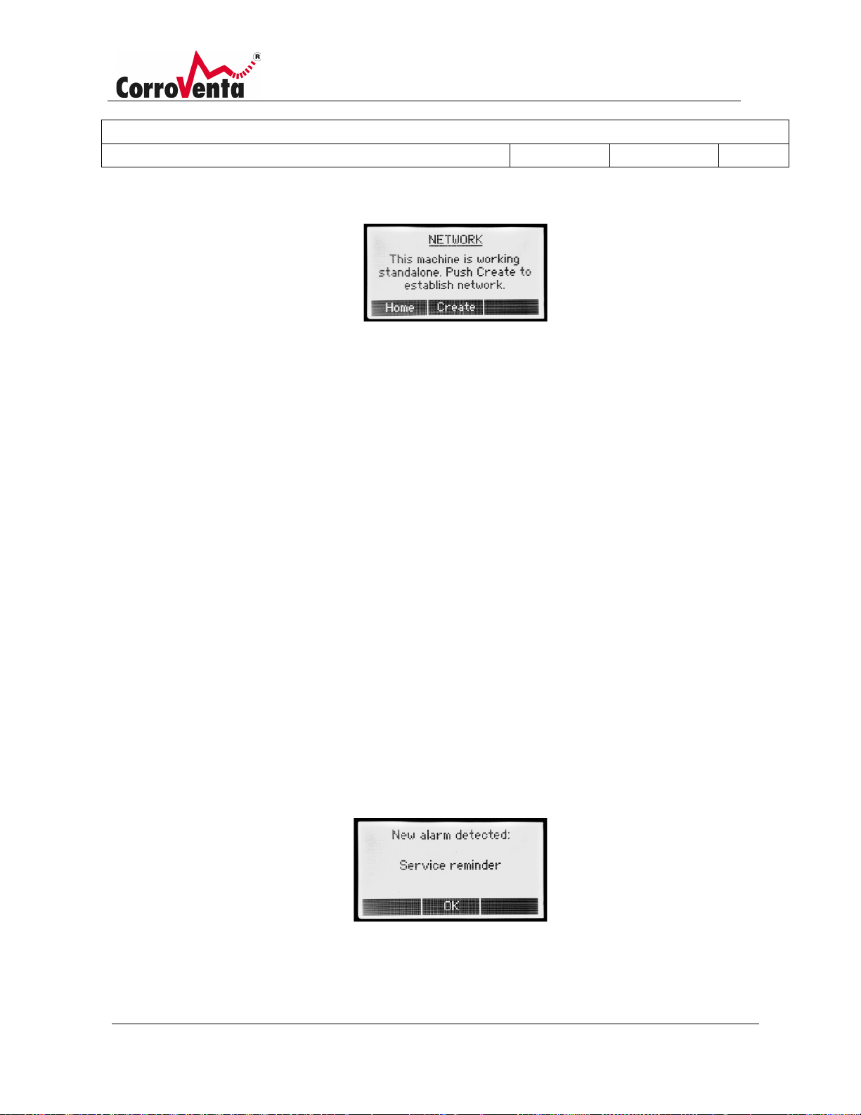
4. Open the network menu as shown below using the right arrow button on the selected master
machine.
(If the menu is not found, the Basic menu system has been activated on the machine. Change
this by opening the setup and maintenance menus and set the menu system to Advanced.)
5. Press <Create> in the network menu and wait whilst the machine establishes the network.
6. Once the network has been created, the display switches between the different slaves at the
top of the screen. If SuperVision has been connected, the text SuperVision appears at the
bottom of the screen. It can take up to one minute for the text to appear.
When the above steps have been followed, all slave machines are controlled by the master. This means
that all slave machines start and stop together with the master. They work with the same settings as
they had before being connected in the network. If the settings need changing, press Change and then
select the slave to be changed via the master. It is also possible to make the necessary changes on the
machine itself. Whilst the slave machine is being changed, via the master, the slave machine's
background lighting flashes so that the user can see which machine is selected.
Maintenance and service
Service reminder
The machine is set to remind you about a service once a year. The reminder is given in the form of an
alarm, but does not affect the operation of the machine. The service reminder function is reset in the
setup and maintenance menus
.
Page 36
Description:
Manual L4 ES HP; L4 ES HP W
Document Number:
1004289
Created By:
MSHN
Revision Approval Date:
2019-06-28
Revision:
A
© Corroventa Avfuktning AB 35 (42)
Filter replacement
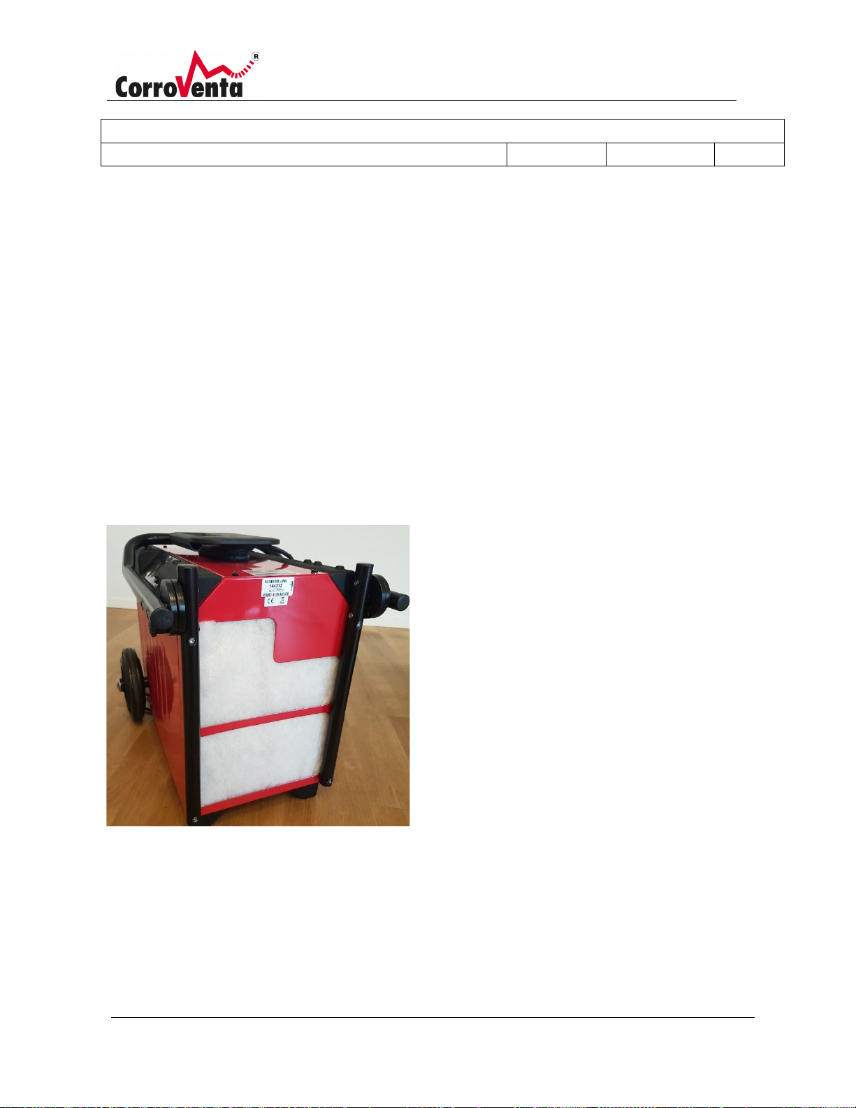
The dehumidifier filter should be replaced regularly, preferably between each work assignment in order
to maintain energy efficiency and to avoid overheating. If the air filter is extremely dirty it must be
replaced more often.
1. Disconnect the power from the dehumidifier.
2. Pull out the dirty filter from the machine and slide in the new one.
3. Reconnect the power to the dehumidifier.
Page 37
Description:
Manual L4 ES HP; L4 ES HP W
Document Number:
1004289
Created By:
MSHN
Revision Approval Date:
2019-06-28
Revision:
A
© Corroventa Avfuktning AB 36 (42)
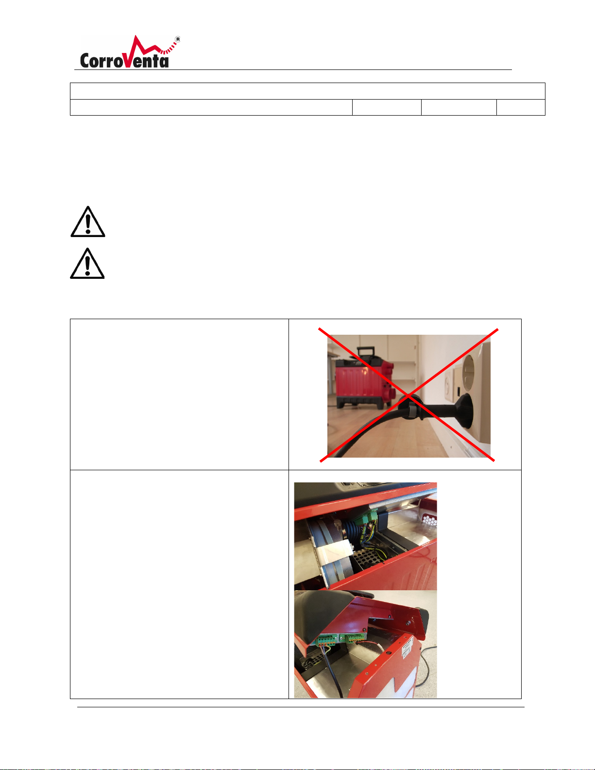
1. Disconnect the machine from the
2. Carefully lift up the cover so that the
Cleaning the rotor insert.
If necessary, it is advisable to clean the rotor in the dehumidifier with compressed air annually or after
use in very dirty environments. Otherwise the rotor's ducts can become blocked, causing restricted air
flow and reduced capacity. To clean the rotor, follow the instructions below:
Disconnect the power from the dehumidifier when cleaning the rotor!
Always wear a protective mask when cleaning the rotor and perform the work
outdoors.
mains supply.
Remove the four screws holding the
upper cover of the dehumidifier.
four cable connections along the front
of the machine are accessible.
Disconnect the connections.
Page 38
Description:
Manual L4 ES HP; L4 ES HP W
Document Number:
1004289
Created By:
MSHN
Revision Approval Date:
2019-06-28
Revision:
A
© Corroventa Avfuktning AB 37 (42)
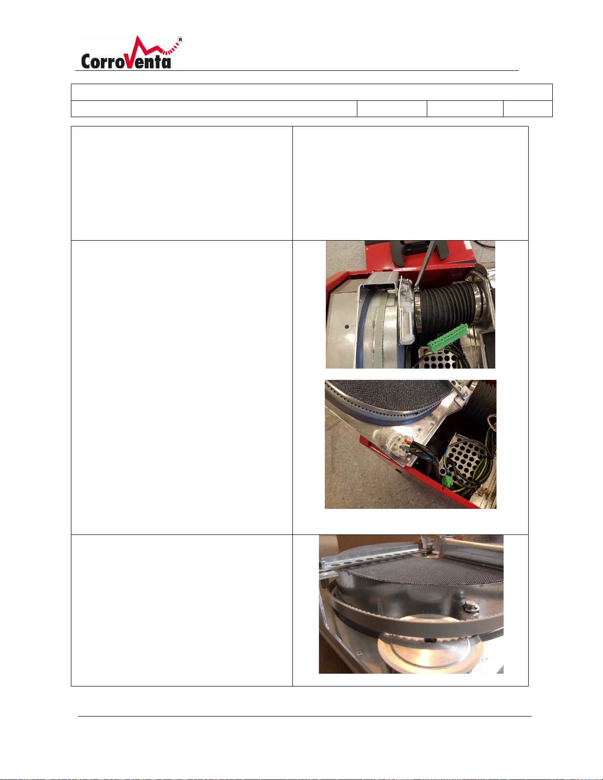
3. Disconnect the wet air hose from the
4. Press the tensioning wheel backward
wet air cover on the cassette.
Pull the entire rotor unit up and lift it
out of the machine. Take care not to
damage the rotor.
Disconnect the AMP connector.
on the rotor unit and slide the belt off
the wheel so that the rotor can rotate
freely.
Page 39
Description:
Manual L4 ES HP; L4 ES HP W
Document Number:
1004289
Created By:
MSHN
Revision Approval Date:
2019-06-28
Revision:
A
© Corroventa Avfuktning AB 38 (42)
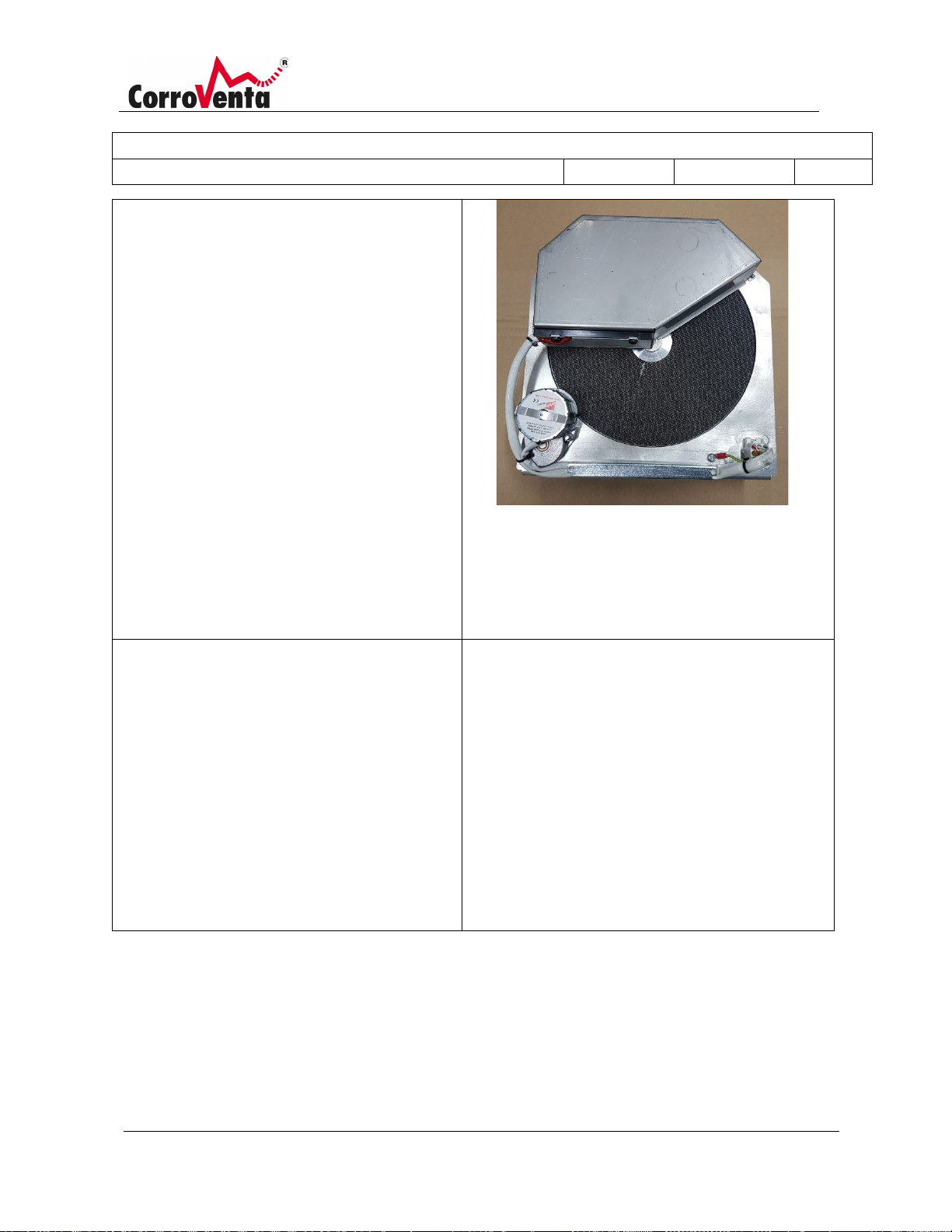
5. Note! Always use a suitable protective
6. Assemble the dehumidifier in reverse
mask when cleaning the rotor and
perform the work in a suitable location
outdoors.
Carefully blow clean the inside of the
rotor using compressed air. Hold the
nozzle about 15 cm from the rotor and
start blowing from the heat shield side
of the rotor. In this way, the air will
flow through the rotor in the opposite
direction to normal. This prevents more
dirt from getting stuck inside.
When you later clean from the other
direction, do not blow air into the heat
shield, otherwise dirt will accumulate
inside. Only blow on the rotor where
the opposite side is free and
unobstructed.
order when the rotor has been cleaned:
• Install the belt.
• Install the AMP connector
• Carefully lower the rotor unit into
the machine.
• Reinstall the wet air hose.
• Reinstall the four connectors.
• When the cover is in place and its
four screws installed, ensure that
the tag washers, one at each end,
are also re-installed.
Page 40
Description:
Manual L4 ES HP; L4 ES HP W
Document Number:
1004289
Created By:
MSHN
Revision Approval Date:
2019-06-28
Revision:
A
© Corroventa Avfuktning AB 39 (42)
Fault symptom
Probable cause
Actions
Premises not
Depending on the situation,
Perform fault tracing as follows until the
which is marked in the middle of the
Article number
Designation
9901100
EXT. Hygrostat, HR1-5 (used together with
Adapter cable 1002816)
1002816
Adapter cable, EXT. Hygrostat
1002817
EXT. Temp and RH sensor, series ES
1004010
Process air filter
1002749
System cable, 0.5 m
1002748
System cable, 5.0 m
Accessories and consumables
The following parts are available as accessories and consumables for L4 ES:
Fault tracing
dehumidified/low
capacity.
the cause of the problem
could be incorrect
installation, e.g. because of
obstructed condensation
water hose, clogged filter,
incorrect settings on the
machine or machine fault.
problem has been identified:
Check the installation - check that the
condensation water hose is not obstructed,
that the dry air damper is in the correct
position and that the hose used on the dry
air side is not trapped or clogged. Ensure
that the air flow is correct.
If the air flow is weak, check the process air
filter and replace if necessary.
Check the machine settings as follows.
Start by checking that the water symbol on
the left-hand side of the display screen
moves as an indication that
dehumidification is in operation. If it does
not move, check the control mode in the
lower, left-hand corner of the display. For
continuous drying, MAN must be indicated
for manual operating mode. If an external
hygrostat is connected and used (operating
mode HYG), check the hygrostat's setting. If
control mode RH, dew point (DP) or mixing
ratio (X) is used, check the setpoint value
Page 41

Description:
Manual L4 ES HP; L4 ES HP W
Document Number:
1004289
Created By:
MSHN
Revision Approval Date:
2019-06-28
Revision:
A
© Corroventa Avfuktning AB 40 (42)
display and adjust if necessary. Check that
The rotor rotates
outlet) or not at all.
Fault with rotor motor or
Contact the dealer for repair.
No air flow, low air
The dry air dampers are
Adjust the position of the Dry air dampers.
the water symbol starts to move.
If the control mode and its settings were
not the problem, continue by checking the
capacity mode that is shown at the upper
right-hand corner in standard view. For
maximum water removal, the text ”MAX”
appears.
ECO mode minimizes the energy
consumption per litre removed water and
the ΔX operating modes are used for drying
local, isolated water damage for example.
If necessary, change operating mode by
opening the menu for capacity mode using
the right-hand arrow button. Follow the
instructions for adjusting the wet air
volume.
anti-clockwise (seen
motor capacitor.
through the dry air
flow
closed
The machine has been set
to standby.
The dehumidifier has been
set to a control mode other
than manual (MAN), the
continuous fan functions
are switched off and the
surrounding humidity is so
low that the machine has
switched to standby.
Press Start to start the machine with the
standard settings or press Resume to start
with the previous settings.
Check the control mode in the lower lefthand corner of the display. For continuous
operation, MAN (for manual operating
mode) should be indicated. Check the
setpoint value if another operating mode is
being used.
For continuous fan operation, use the righthand arrow button to open the menu for
fan mode and activate continuous fan
operation.
Page 42
Description:
Manual L4 ES HP; L4 ES HP W
Document Number:
1004289
Created By:
MSHN
Revision Approval Date:
2019-06-28
Revision:
A
© Corroventa Avfuktning AB 41 (42)
The machine is controlled
Adjust the hygrostat's setpoint value if
Dry air volume Max/ECO (m3/h)
380/300
Cooling air volume Max/ECO (m3/h)
100/60
Drying capacity at 20°C, 60% Max/Low (litres/day)
12/9
Ø dry air outlet (mm)
2 x 100, 2 x 50
Sound level, Max/ECO dBA (3 m)
approx. 50-58*
Voltage
230 VAC/50 Hz
Rated power Max/ ECO (W)
1300/1000
Height x width x length (mm)
495 x 295 x 550
Weight, kg 23.5
Dry air volume Max/ECO (m3/h)
380/300
Cooling air volume Max/ECO (m3/h)
100/60
Drying capacity at 20°C, 60% Max/Low (litres/day)
12/9
Ø dry air outlet (mm)
2 x 100, 2 x 50
Sound level, Max/ECO dBA (3 m)
approx. 50-58*
Voltage
230 VAC/50 Hz
Rated power Max/ ECO (W)
1300/1000
Height x width x length (mm)
495 x 440 x 620
Weight, kg 30
by a timer and is currently
in standby mode.
Technical data
L4 ES HP
*Sound level varies depending on the installation.
appropriate.
L4 ES HP W
*Sound level varies depending on the installation.
Page 43
Description:
Manual L4 ES HP; L4 ES HP W
Document Number:
1004289
Created By:
MSHN
Revision Approval Date:
2019-06-28
Revision:
A
© Corroventa Avfuktning AB 42 (42)
Accuracy class
Class B
Rated Operating Conditions
Voltage
230VAC
Frequency
50Hz
Power factor
0.5ind. to 0.8cap.
Current
I st
0.02A
I min
0.25A
I tr
0.5A
I ref
5A
I max
45A
Operating temperature
-25°C to + 55°C
Climate
Non-condensing
Environment/position
Closed location
Electromagnetic environment class
E2
Mechanical environment class
M2
Max capacity of energy register
9 999 999,9 kWh
Notified body
0402
CEMP Energy Metering Data
NOTE: The below data, temperatures and current levels etc., relate to the built-in energy metering function,
the CEMP, alone and not to the complete machine.
The CEMP declaration of conformity is available at www.corroventa.com/mid-certificate/.
Page 44

DO YOU HAVE QUESTIONS OR NEED HELP?
Visit www.corroventa.com or call +44(0) 161-2449523 to speak with an expert.
We have the knowledge and the equipment to find a solution as eciently as possible.
Corroventa develops, manufactures, sells and hires out high quality products
for dealing with water damage, moisture, odours and radon. We are one of the
market leaders and specialise in innovation within the industry. Our products are
compact, eective, ergonomic and energy ecient. In emergency situations and
during flooding, Corroventa’s customers have access to one of the largest rental
parks in Europe. We have sales oces and machine depots in several locations
throughout Europe. All our manufacturing takes place in Bankeryd, Sweden.
www.corroventa.com
CORROVENTA LTD
Unit 29, Irlam Business Centre, Irlam, Manchester
England, M44 6GP • Tel +44(0) 161-2449523
 Loading...