

Page 1
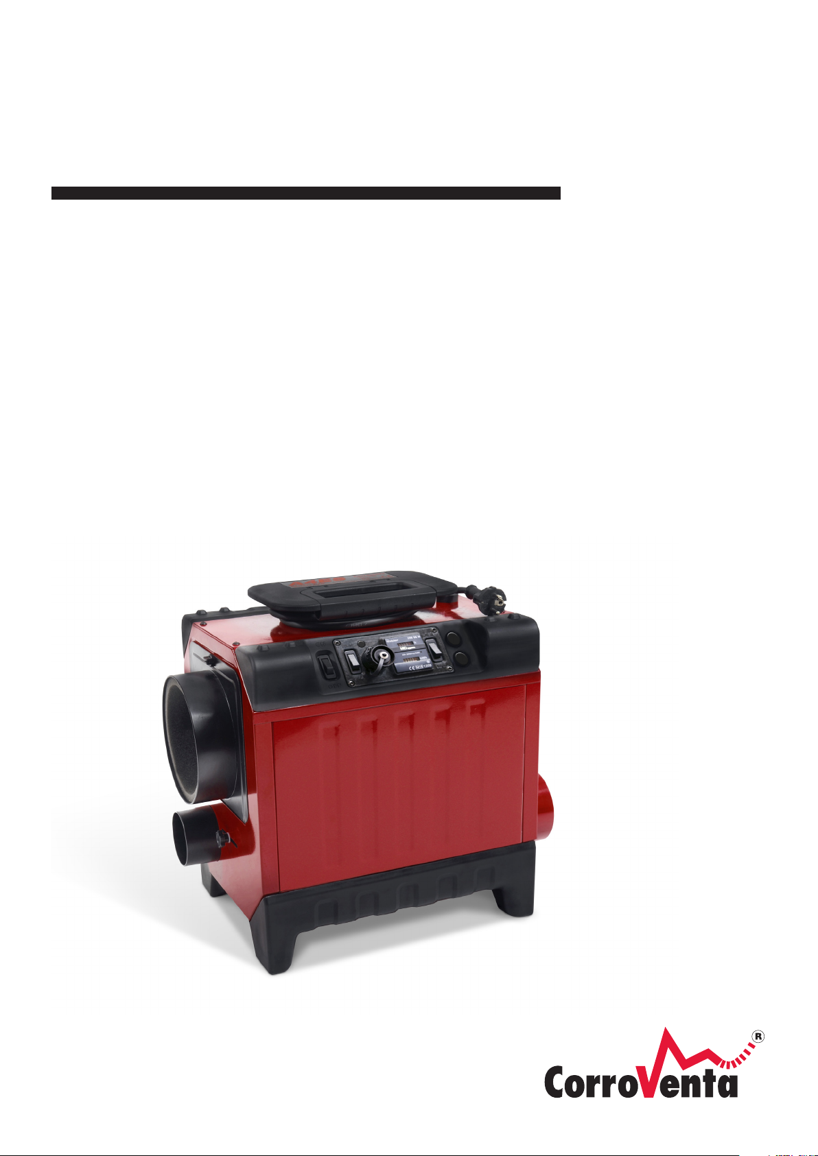
A2 / A4
ADSORPTION
DEHUMIDIFIERS
USER MANUAL
Page 2

Page 3

© Corroventa Ltd.
2017.05
1 (17)
Contents
Area of use .......................................................................................................................................... 2
Delivery check ..................................................................................................................................... 2
Manufacture directive ......................................................................................................................... 3
Safety information ............................................................................................................................... 4
Relative humidity and its impact on materials .................................................................................... 5
How to select dehumidification technology for a given situation ...................................................... 5
This is how the drier works ................................................................................................................. 6
Dehumidification process .................................................................................................................... 6
Product overview ................................................................................................................................ 7
Drying methods ................................................................................................................................... 8
General drying, room dehumidification .......................................................................................... 8
Drying framed flooring and beams ................................................................................................. 9
Suction drying ................................................................................................................................ 10
Pressure drying .............................................................................................................................. 11
Installation ......................................................................................................................................... 12
Maintenance and service .................................................................................................................. 13
Filter replacement ......................................................................................................................... 13
Cleaning the rotor insert. .............................................................................................................. 14
Accessories and consumables ........................................................................................................... 16
Fault tracing ........................................................................................................................................... 16
Technical data ....................................................................................................................................... 17
Page 4
© Corroventa Ltd.
2017.05
2 (17)
User instructions CTR A
• Energy efficient
• Service-friendly
• High capacity level
• Time and kWh meter
• Robust
• Very quiet
Drier CTR A
1 x
Extra process air filter in addition to the one in
the dehumidifier
2 x
Manual
1 x
Area of use
The CTR A adsorption dehumidifiers have been developed and designed for drying water damage and
building moisture. CTR A has a robust analogue control system with fewer functions than the sister
machines in the ES range.
The unit also has a folding handle with a holder for the electrical cable, while its light weight means
it is easy to carry and install. The durable but flexible feet protect the floor surfaces and also make it
possible to stack the machines. The driers have a naturally robust construction that gives a long
service life.
By using the adsorption principle, the dehumidifier does not have the same temperature
dependence as a condensing drier. It also works well below the freezing point. Furthermore, an
adsorption dehumidifier is capable of creating drier air, a greater difference between the water
content of incoming and outgoing air, than a condensing drier. It can be used for drying rooms and,
using turbines, also for drying layered structures. The latter can be dried by suction, as well as
pressure drying.
Properties:
Delivery check
CTR A is supplied with the following parts in the package:
Page 5

© Corroventa Ltd.
2017.05
3 (17)
Manufacture directive
The machines in the CTR A range are CE approved.
Limitation of Liability
• Incorrect installation and/or incorrect use can cause property damage as well as injury.
• The manufacturer assumes no liability for property damage or injury incurred as a result of
failing to follow these instructions, the machine being used for purposes other than those
intended or failure to observe these warnings. Such damage, injury or liability is not covered
by the product warranty.
• The product warranty does not cover consumable parts or normal wear.
• The purchaser is responsible for checking the product upon delivery and before use to
ensure it is in good condition. The product warranty does not cover damages resulting from
the use of defective products.
• No changes or modifications to the machine may be performed without written consent
• from Corroventa Avfuktning AB.
• The product, technical data and/or installation and operating instructions are subject to
change without notice.
• These user instructions contain information protected by applicable intellectual property
laws. No part of these user instructions may be reproduced, stored in a retrieval system or
transmitted to third parties in any form or by any means without the prior written consent of
Corroventa Avfuktning AB.
Any comments regarding the content of this document must be sent to:
Corroventa Avfuktning AB Tel: +46 (0)36-37 12 00
Mekanikervägen 3 Fax: +46 (0)36-37 18 30
SE-564 35 Bankeryd E-mail: [email protected]
SWEDEN
Page 6

© Corroventa Ltd.
2017.05
4 (17)
Safety information
This device is not intended for use by persons with reduced physical, mental or sensory impairments
nor other persons lacking the necessary skills or experience, unless supervised or instructed by
another person with responsibility for their safety.
Children may only use the device under the supervision of an adult to
ensure that the device is not used as a toy.
Electrical installations carried out in connection with the drier installation must be performed by a
professional in accordance with local and national regulations.
In addition, the following warnings and instructions must be read and followed:
1. The drier is only intended for indoor use.
2. The drier must not be powered on before installation is completed in accordance with this
manual.
3. The drier must not be covered because this may lead to overheating and fire.
4. The drier must not be used as a work table, trestle or stool.
5. The drier is not intended to be stood or climbed on.
6. Never operate the drier without installing the filter as this may damage the drier. Ensure that
the filter is clean. If it is blocked, the machine may overheat.
7. Do not allow the drier to draw in alkaline chemicals or organic substances with a high boiling
point, such as oil, grease, solvents, boracol or similar. These can damage the rotor.
8. The drier may not be used in areas where it can produce explosive gases.
9. Do not insert objects into the intake or exhaust as this could damage the drier and injure
people.
10. Place the drier on a firm and flat surface so that it cannot overturn.
11. Keep children, animals and bystanders away from the workplace.
12. Contact the supplier if the drier is damaged or if the plug or the electrical cable are damaged.
Do not make any repairs yourself if you have not undergone the supplier's training.
13. Do not damage the electrical cable. The cable must not run through water or over sharp
edges.
14. Never carry or drag the drier by the cable.
15. Using electrical equipment in very damp or wet conditions can be dangerous. Do not operate
the drier if it is standing in water.
16. The drier may only be connected to a grounded socket with voltage according to the rating
plate.
17. It is recommended to use an earth-fault breaker to minimise the risk of electric shock.
18. Water must not come into contact with the drier's electrical components. If it does, ensure
that they are dried thoroughly before the drier is used again.
19. Never open the drier for cleaning or service without first ensuring that the drier is
disconnected from power.
20. Repairs and maintenance of the drier's electrical system must be performed by a qualified
electrician.
21. Wet air hoses/pipes used and connected to the drier must be corrosion resistant and able to
withstand heat of 80°C.
22. The drier must not be used with accessories other than those described in this manual or
approved by Corroventa Avfuktning AB.
Contact the supplier of this drier for further advice on the safety and use of the product.
Page 7
© Corroventa Ltd.
2017.05
5 (17)
Relative humidity and its impact on materials
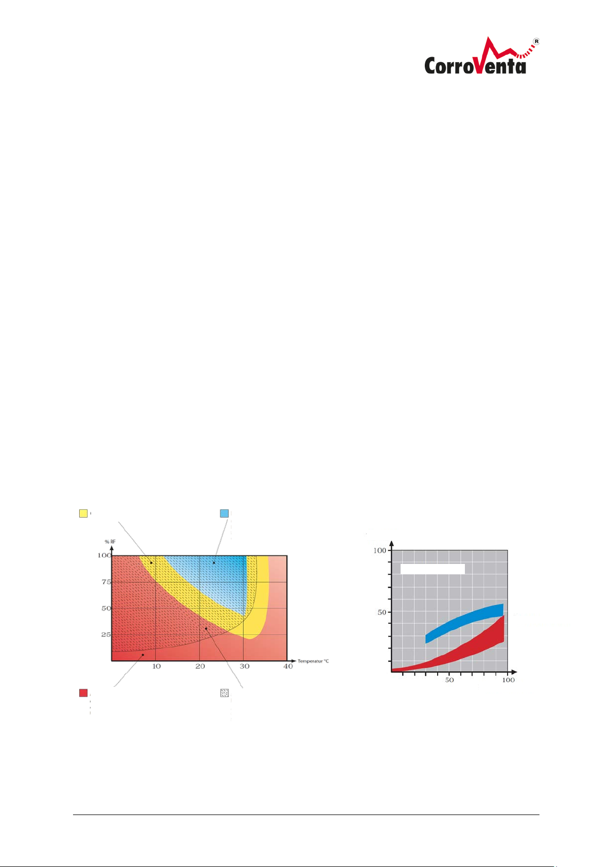
TRANSITION Z ONE
CONDENSING DRIER
Superior performance within the blue area
–
work well or not at all in the red area.
ADSORPTION DEHUMIDIFIER
Superior performance in the red area
also works in the yello w and blue a rea.
ADSORPTION DEHUMIDIFIER WITH
CONDENSER
Drier combined with air
condenser (LKV)
area.
Dry air RH
Dry air quality 20°C
Condensing driers
Adsorption
dehumidifie rs
Process air RH
All air contains a greater or lesser degree of moisture. We can’t see it with the naked eye until it
appears in the form of small water drops against a cold metal or glass surface for example. However,
before it is visible, moisture is already causing problems by affecting materials and manufacturing
processes, causing corrosion and growth of micro-organisms.
Air moisture is measured and usually given in relative humidity (% RH). It is a measurement of how
much water vapour the air contains over how much it can hold in total at a given temperature and
pressure. The higher the temperature, the more water the air can hold, but it is the relative humidity
that is calculated and must be controlled to prevent corrosion or mould growth.
At 100% RH the air is saturated and the moisture falls in the form of small water droplets. Steel
corrodes at 60% RH and at 70% RH there is a risk of mould. A rule of thumb is that 50% RH is a good
climate for most materials.
How to select dehumidification technology for a given situation
The adsorption principle has the advantage of not having the same temperature dependence as
condensing dehumidification. Adsorption also works way below freezing whilst condensing
dehumidification capacity decreases sharply with decreasing temperature, which is illustrated in the
graph below to the left.
As a general tip when choosing the technique for the relevant drying situation, it can be said that
adsorption dehumidification is the primary choice for drying in unheated spaces or when material
drying is required. The latter is justified by the adsorption dehumidifier producing drier air, i.e.
provides a greater difference between the incoming and outgoing air's moisture content calculated
in grams per cubic metre (ΔX), which can be seen using the graph to the right below and which is
decisive for the rate of drying. Layered structures are dried by the machine being installed, with the
turbine, for suction or pressure drying.
As the graph above shows, condensing driers are used in hot and humid spaces as long as room
drying is required.
can be used i n the yellow area – does not
–
cooled
– works in the shaded
Page 8
© Corroventa Ltd.
2017.05
6 (17)
This is how the drier works
The desiccant used in CTR A is silicate gel, which can be regenerated an almost unlimited number of
times. Silicate gel is a crystal with a lot of microscopic pores that make the total surface very large. A
2
single gram has an active surface of 500 to 700 m
. Silicate gel is very powerful and can absorb a
volume of water of up to 40% of its own weight. It is not water soluble and therefore cannot be
washed away or diverted to the passing air.
Dehumidification process
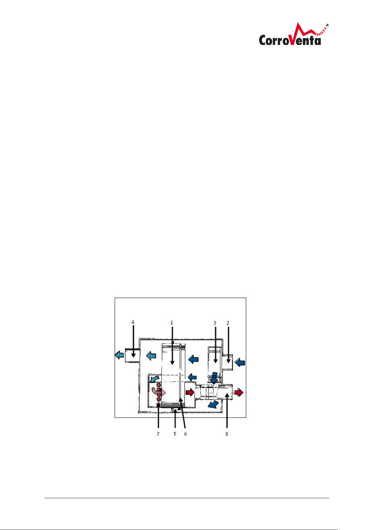
The desiccant is placed in a rotor (1). The air to be dried is sucked in through the inlet (2) by
means of a process air fan (3).
The air passes a filter and then the drying rotor after which the dehumidified air goes through
the dry air outlet (4) to the area to be kept dry. The rotor has axially directed air ducts and
consists of a highly active desiccant, silica gel, bonded in a ceramic structure. The axially
directed air ducts in the rotor give laminar flow with minimal pressure drop.
The rotor rotates by means of a drive motor (5) and a drive belt (6). The moisture that
is adsorbed in the rotor is driven out by a small portion of the process air being heated by the
heater (7) and then passing a smaller part of the rotor, which is thus regenerated and cleaned
by the countercurrent principle.
The wet air is removed via the outlet (8) to the surroundings.
Page 9
© Corroventa Ltd.
2017.05
7 (17)
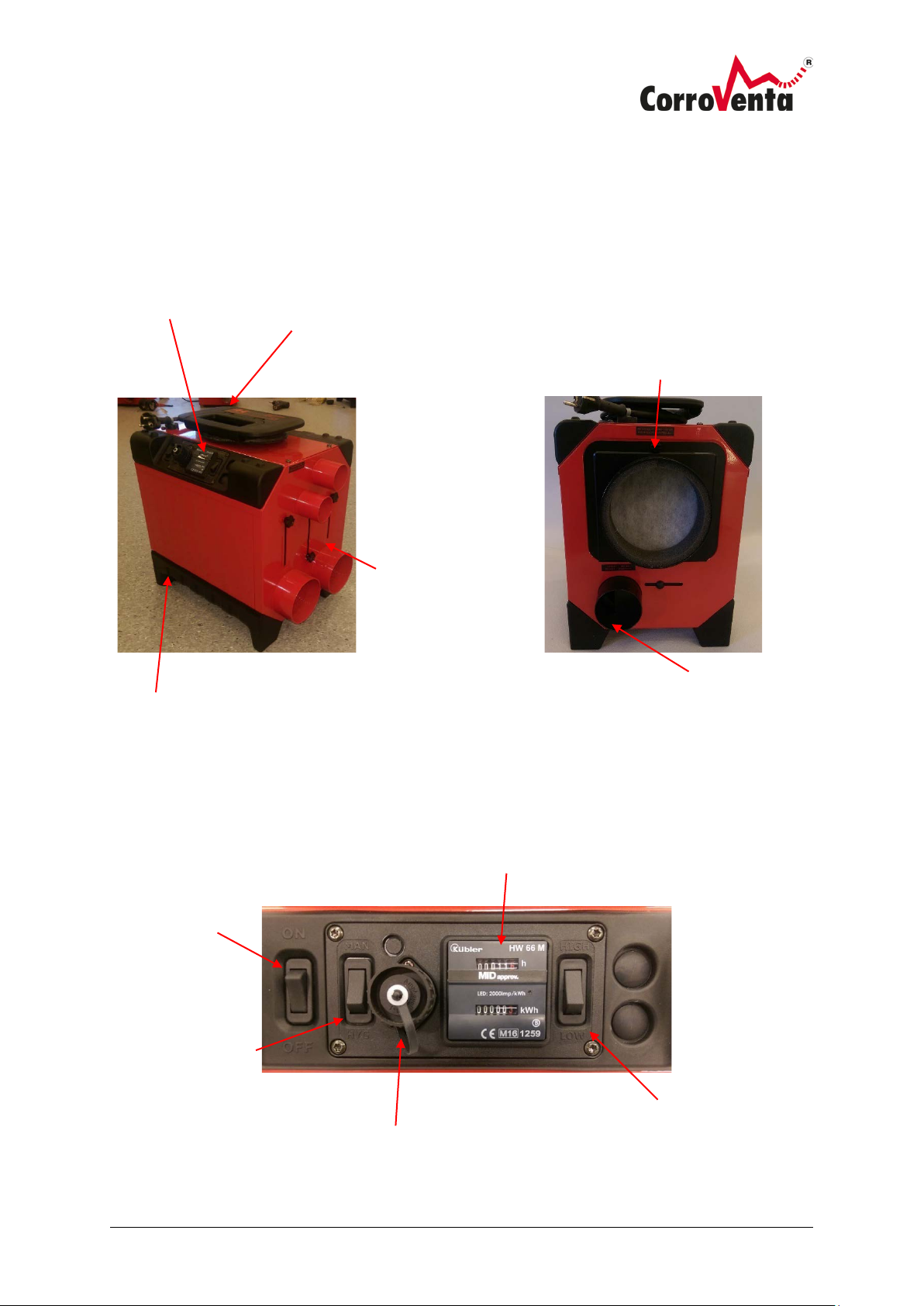
Product overview
Folding handle with
Control panel
Dry air outlet with
Support feet made of durable
Process air inlet with
cover and filter
Wet air outlet
Man/Hyg button/selector
Connection for
Time and kWh meter
ON/OFF
High/low fan speed
The images below present CTR A4 with all external parts and controls. CTR A2 is shorter and has
fewer dry air outlets, but otherwise has the same properties.
integrated cable reel
damper
1 x 100 mm
2 x 50 mm
polyurethane
Manual (continuous
operation) or control via
connected hygrostat (Hyg).
hygrostat
Page 10
© Corroventa Ltd.
2017.05
8 (17)
Drying methods
Cover local damage with plastic when drying to increase the drying rate and reduce
energy consumption.
The following outlines the basics of different drying methods that can be applied to CTR A and, in
some cases, additional equipment from Corroventa's product range. The descriptions are only an
overview, and in the event of any doubt about how any given situation should be handled please
consult an experienced dehumidification technician.
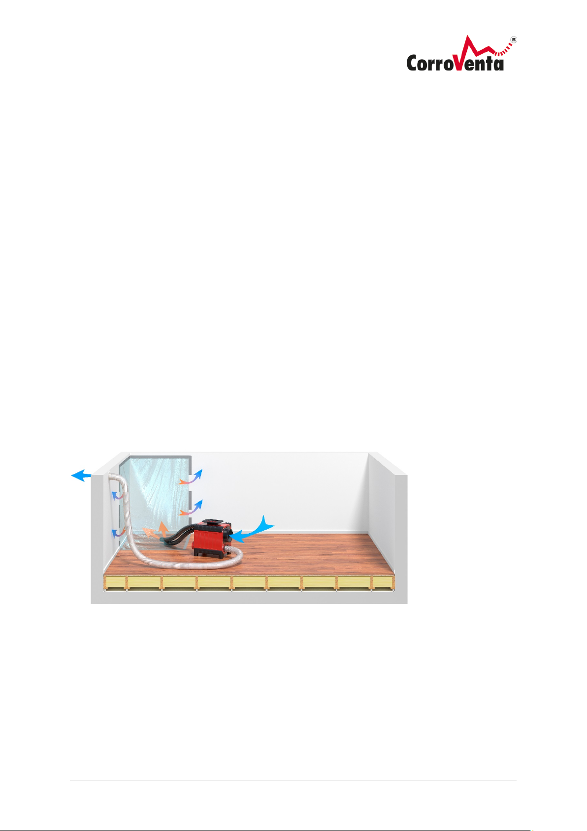
General drying, room dehumidification
An adsorption dehumidifier like CTR A produces such dry air that an air turnover of between one and
two times per hour are sufficient, compared with condensing driers where turnover should instead
be between three and four times per hour. Approx. 300 m
area if the roof height is 2.5 metres.
As with all dehumidification, regardless of type or model, it is important to ensure that the area to be
dehumidified is well sealed so that the process is performed as fast and as energy efficiently as
possible. Windows and doors to the area must be closed, and if there are not any, plastic or other
temporary partitions must be used.
3
/h is enough for a room with a 50 to 60m
2
If the spread of the damage is limited it is advisable to cover it with plastic and let the dry air flow in
under the plastic via hose. Leave openings at the edges where the air can exit. This makes the
process faster and consumes less energy.
Page 11
© Corroventa Ltd.
2017.05
9 (17)
Drying framed flooring and beams
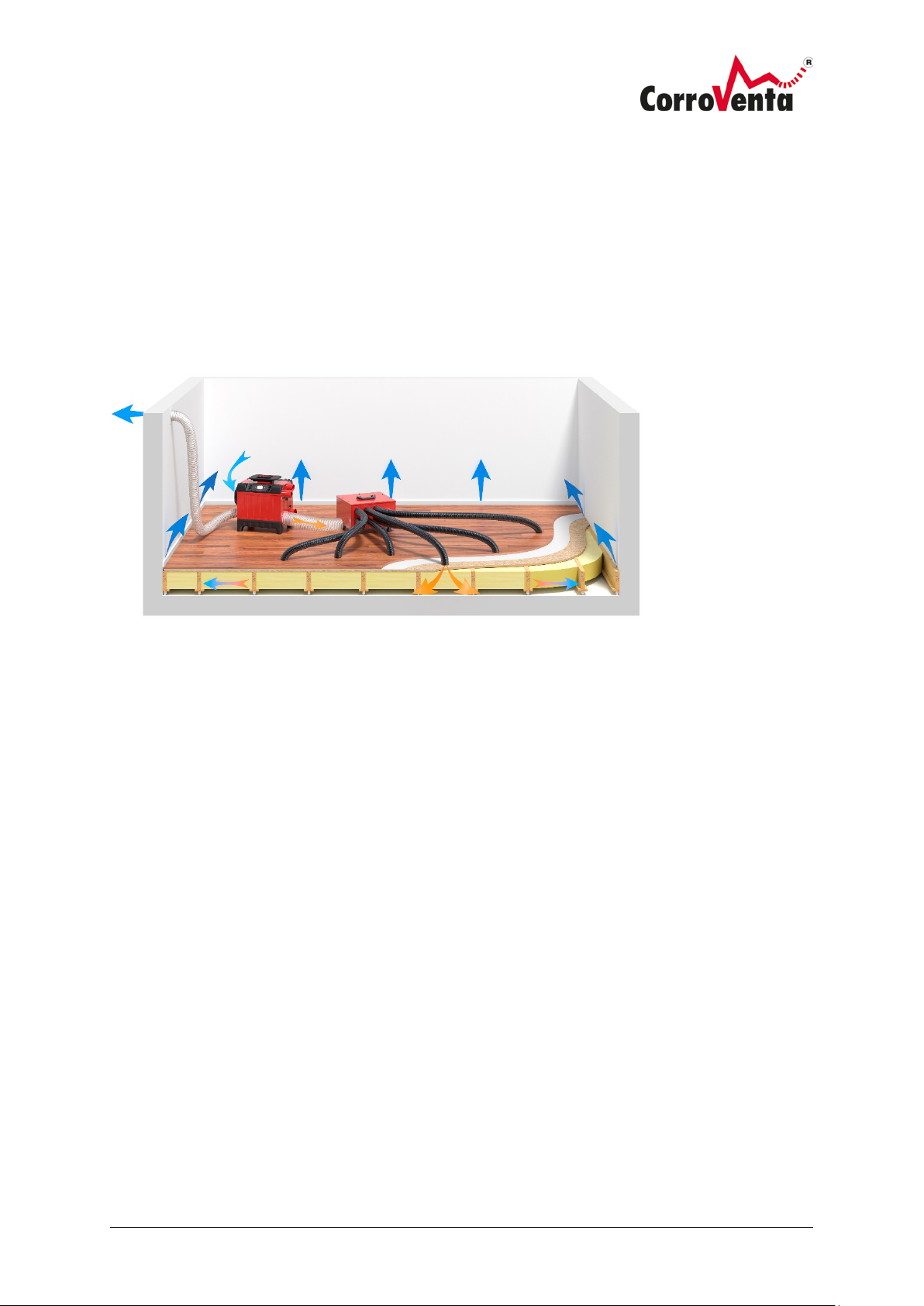
Drying beams using a fan. Note that the drier to the right is not directly
connected to the fan. The dry air hose is only placed close to the fan.
For framed flooring and beams with easy-to-dry insulation, for example, glass wool, CTR A can be
used with a high-pressure fan such as HP2000 according to the schematic diagram below. Remember
that the capacity of this fan far exceeds that of the drier and therefore allow the fan to "draw the bad
air". The diagram below shows this by the dry air hose from the drier to the right not being
connected directly to the fan, but placed next to it instead. In this way, the fan can draw enough air
without drawing excess air through the drier affecting its function and efficiency.
Page 12
© Corroventa Ltd.
2017.05
10 (17)
Suction drying
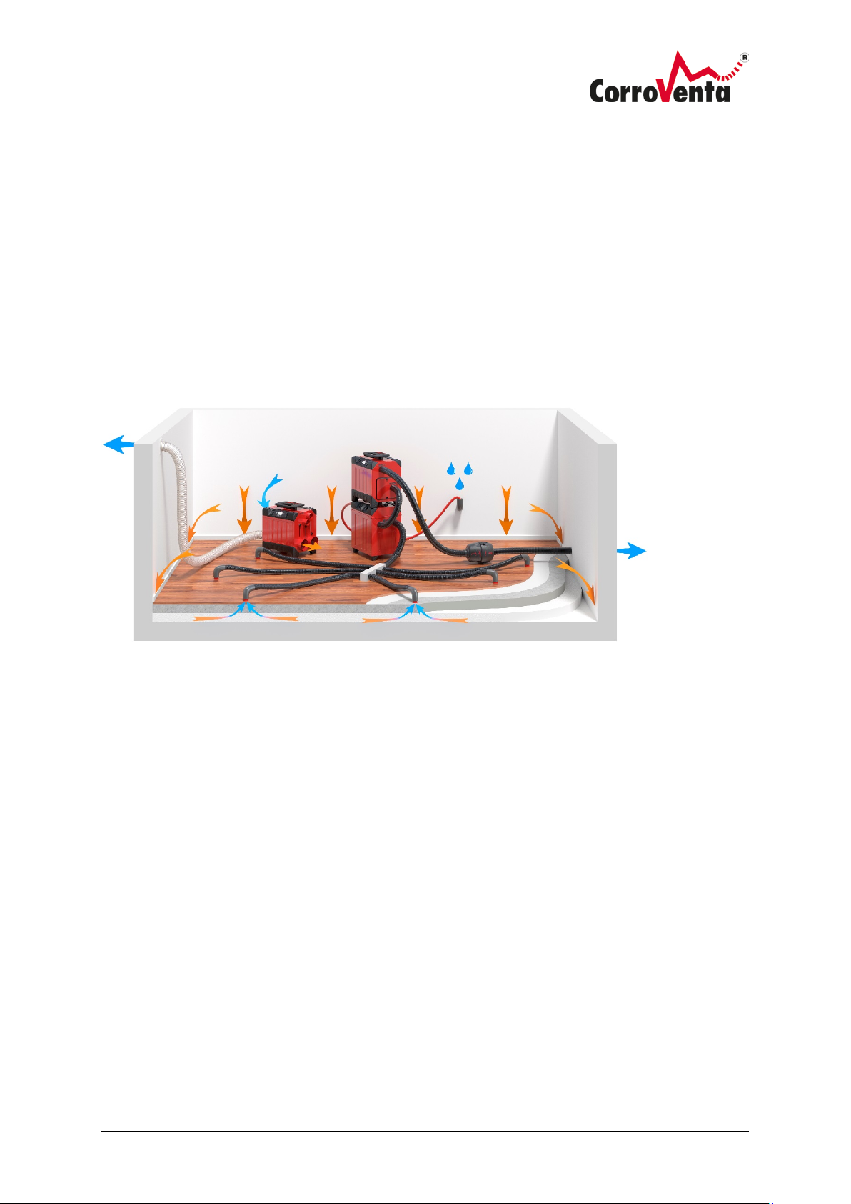
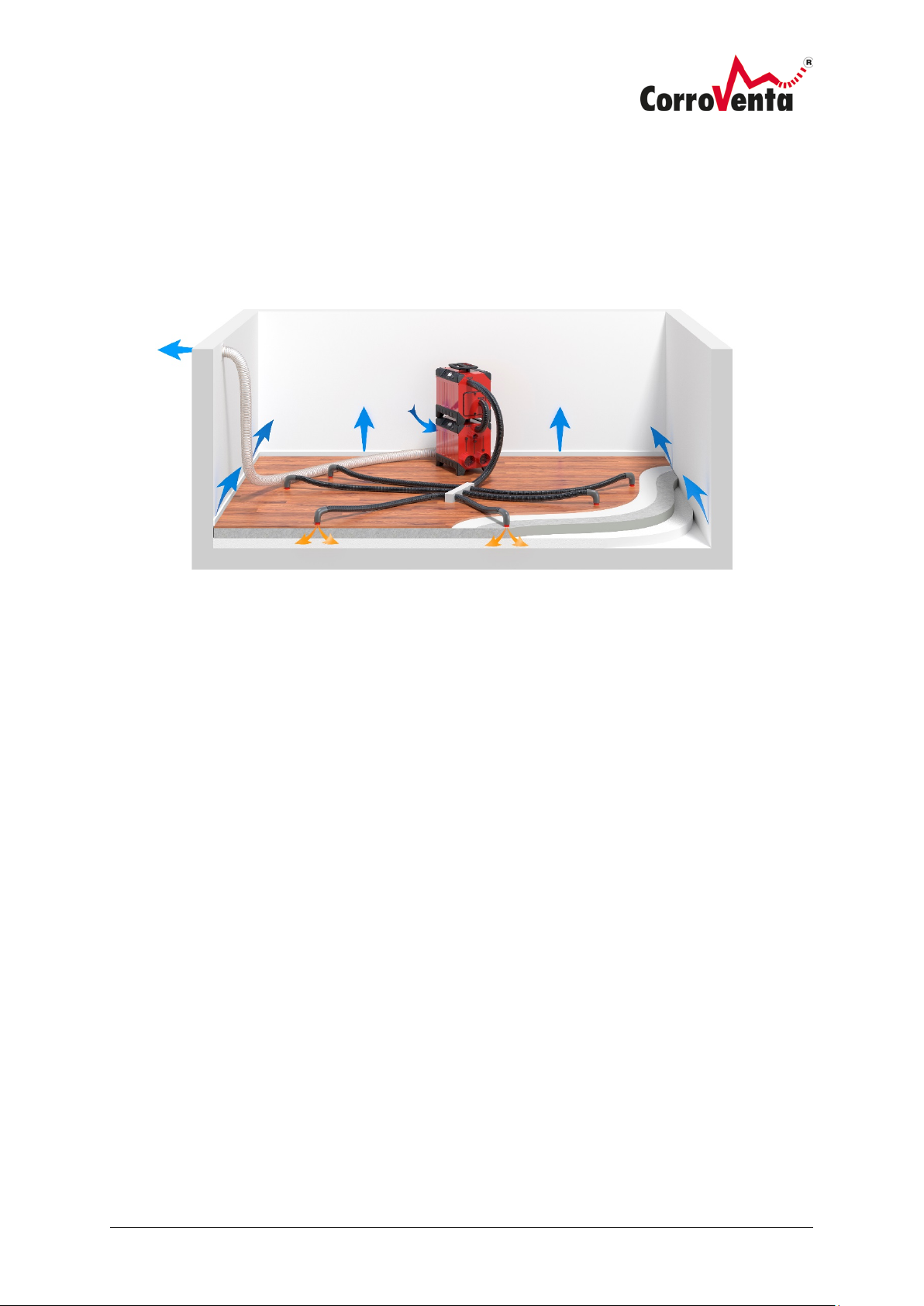
Suction drying. The drier dries the air in the space and the turbines draw air out of the layered
structure, resulting in dry air being drawn down into it.
When suction drying layered structures, use CTR A together with a turbine according to the
schematic diagram below. Connect the turbine or turbines so that they draw air out of the layered
structure via hose system, water separator and filter, and then evacuate the air via the hose out to
the surroundings. Place the drier in the room and route its wet air hose out of the room normally. In
this way, the turbine will draw in dry air into the layered structure and this is how the method got its
name.
Use of a water separator is crucial to prevent water being sucked into the turbine and damaging the
motor.
Page 13
© Corroventa Ltd.
2017.05
11 (17)
Pressure drying
When pressure drying, use CTR A together with a turbine according to the schematic diagram below.
Pressure drying is two to four times faster than suction drying and is therefore the primary choice for
a layered structure, if there are no obstructions.
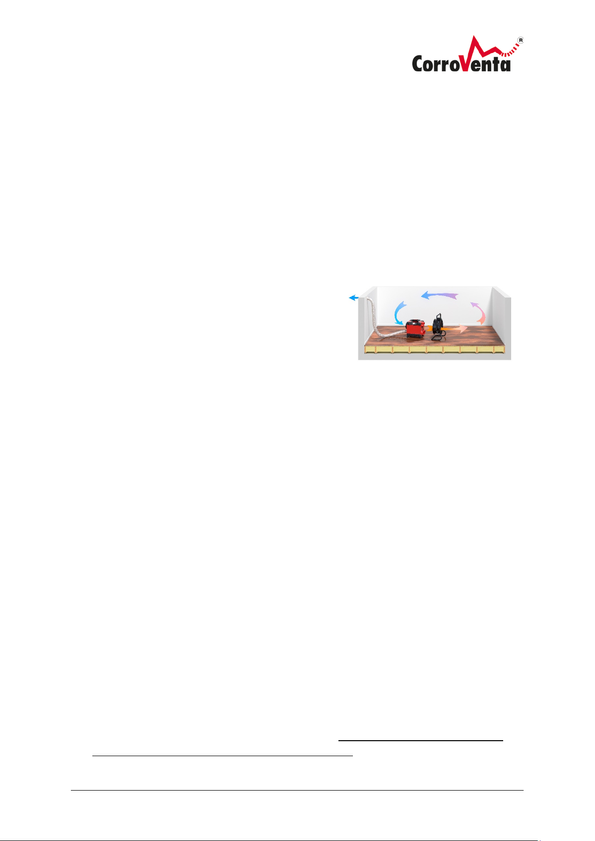
Pressure drying. The turbine is fed with dry air from the drier and forces
it into the layered structure.
During pressure drying, dry air is routed from CTR A to a turbine and then forces this air into the
layered structure. In this way, warm and dry is forced down into the structure, which achieves the
material temperature and thus increases the rate of the drying process. Wet and cool air leaks into
the room through the gaps between the floor and the wall or via drilled check holes, and is then resucked into the drier as process air.
Before starting pressure drying, suction drying is required to evacuate all free-flowing water so that
this is not forced into other parts of the structure. Furthermore, it is important to balance the turbine
capacity with the drier's so that not too much air is drawn through the latter, which interferes with
its function and performance.
Pressure drying may release fibres/particles from the layered structure into the indoor air and if this
is a potential problem another method should be applied.
Page 14
© Corroventa Ltd.
2017.05
12 (17)
Installation
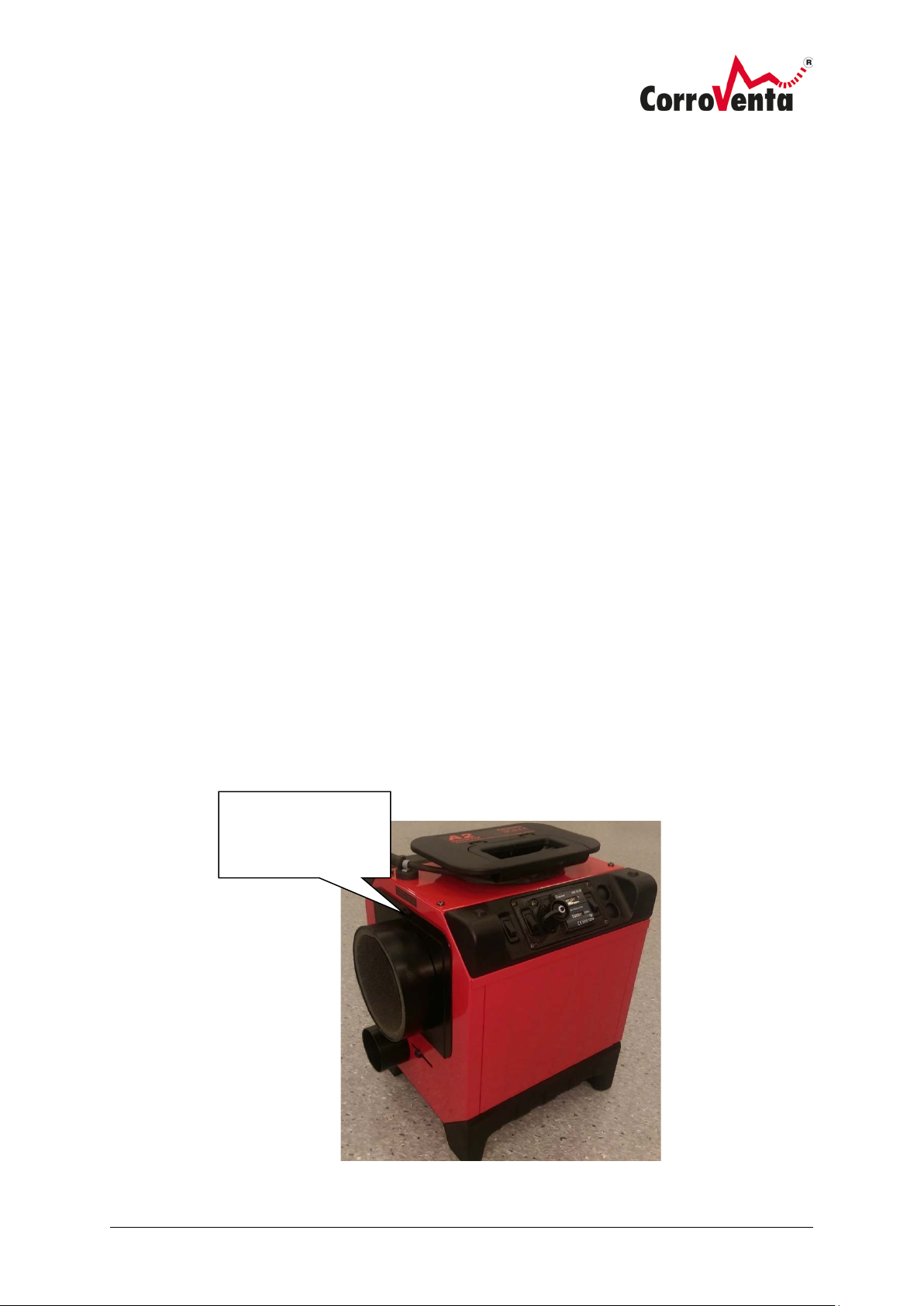
The wet air must always be evacuated via
hose out from the space to be dried. The
image shows room drying.
Place CTR A on a flat and level surface, so that it cannot tip over causing damage to the machine or
other property or injury to people.
Connect a hose to the wet air connector to lead the wet air out of the space to be dried. The wet air
hose should have a smooth inside and should be as short as possible, no longer than 5 metres, for
optimum function and highest capacity. If a longer wet air hose is necessary for the installation, the
high static pressure that the machine has is capable of dealing with a hose of up to ten metres but
the dry air must then be restricted, which can be done without tools or instruments and yet with
sufficient precision as follows:
1. Connect a 5 metre long hose and blow the wet air into your face to get an idea of the airflow.
2. Now connect the longer hose, up to ten metres, and restrict the dry air using the damper until the
flow to the face feels as strong as with the shorter hose.
In the event of problems with condensation in the wet air
hose, if best solution of shortening the hose is not possible,
this can be alleviated by restricting the dry air slightly,
which leads to an increased volume of wet air. Performance
is reduced slightly so this method must be evaluated from
case to case. Another method is to make holes in the hose
for the condensation and to use a container.
Installation in brief (also see page 7, Overview, controls and connections):
1. Place the drier in a location where the wet air hose reaches the intended evacuation point.
Ensure that it is on firm and level ground so that it cannot tip over.
2. Connect the cable to 1-phase, 230 V electrical socket fused to 10A or maximum 16A. As the
machine is usually used in damp, wet areas, the use of a earth-fault breaker is strongly
recommended.
3. Set the machine to Manual (Man) mode with the left button on the control panel. Check that
the fan starts by the machine blowing air. Look into the wet air connector and check that the
rotor rotates anti-clockwise. Hold your hand by the wet air connector and check that the wet air
feels warm. Note that the machine needs to run a few minutes before this can be checked.
4. Connect the wet air hose and route it out through the intended evacuation point (hole in the
wall, window, or whatever is relevant). Ensure that the hose not trapped or obstructed
anywhere.
5.
Connect any dry air hoses, turbine or whatever is relevant for the situation. Room and suction
drying usually occurs with the 100 mm dry air connector open and the 50 mm connectors
closed. The latter can be used to lead dry air to a separate area if necessary. During pressure
drying with T200, connect this to a 50 mm connector. Leave the other 50 mm connector open
but close the 100 mm connector. During pressure drying, ensure that the turbine or turbines
total capacity (m
3
/h) does not exceed that of the drier. Regardless of the area of use, ensure
that not all dry air connectors are closed at the same time.
Page 15
© Corroventa Ltd.
2017.05
13 (17)
6. If using a hygrometer, connect it to the hygrometer connector on the control panel and set the
Turn anti-clockwise
desired setpoint value. The red Man/Hyg button must also be in the Hyg. position. Verify that
the Ventilation button is in the ”On” position, provided there is no special reason it should not
be. If this is off, the fan only runs when dehumidification is in progress, which reduces the noise
further, but it also means that the air does not circulate continuously, which can reduce the
drying effect.
7. Inspect the installation and if there are no faults and, if not already connected, reconnect the
cable in the electrical socket so that the drier starts.
Maintenance and service
Filter replacement
The drier filter should be replaced regularly, preferably between each work assignment in order to
maintain energy efficiency and to avoid overheating. If the air filter is extremely dirty it must be
replaced more often.
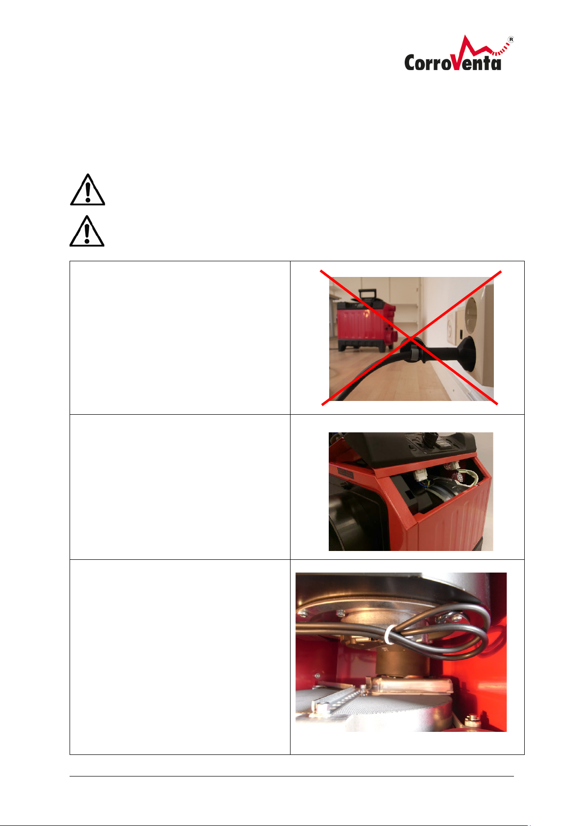
1. Disconnect the power from the drier.
2. Turn the button on the filter cover anti-clockwise and open the cover. Pull out the dirty filter
from the machine and slide in the new one. Close the cover and turn the button clockwise to
lock it.
3. Reconnect the power to the drier.
to open the filter
cover.
Page 16
© Corroventa Ltd.
2017.05
14 (17)
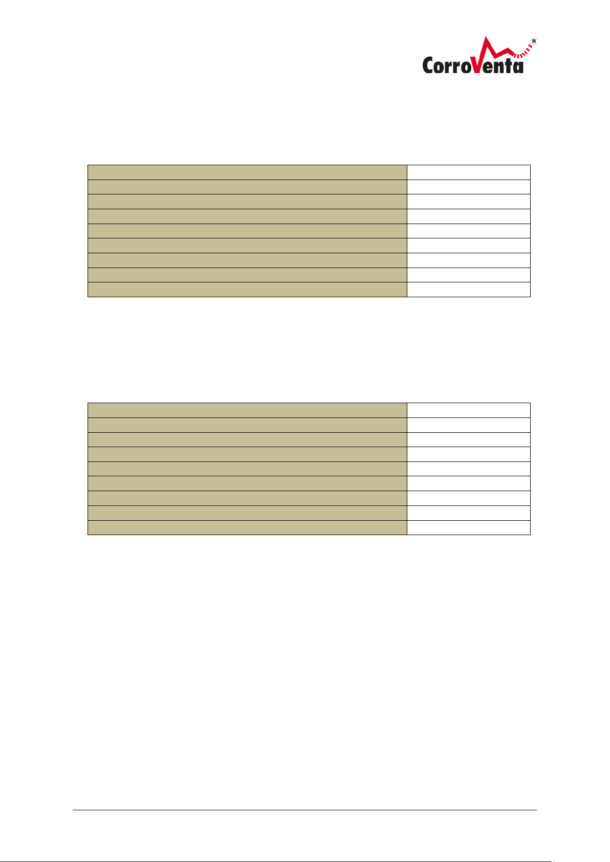
Cleaning the rotor insert.
1. Disconnect the machine from the
2. Carefully lift up the cover so that the
3. On A2 and A4 you must insert your
If necessary, it is advisable to clean the rotor in the drier with compressed air annually or after use in
very dirty environments. Otherwise the rotor's ducts can become blocked, causing restricted air flow
and reduced capacity. To clean the rotor, follow the instructions below:
Disconnect the power from the drier when cleaning the rotor!
Always wear a protective mask when cleaning the rotor and perform the work
outdoors.
mains supply.
Remove the four screws holding the
upper cover of the drier.
two cable connections along the front
of the machine are accessible.
Disconnect the connections.
hand between the fan and the rotor
unit and pull off the internal wet air
hose from the nipple.
Pull the entire rotor unit up and lift it
out of the machine. Take care not to
damage the rotor.
On A2 is it easier to remove the fan
bracket. Remove the two screws
holding the fan bracket in place. They
are located between the machine feet.
When the screws have been removed,
pull the fan bracket up and remove it.
Page 17
© Corroventa Ltd.
2017.05
15 (17)
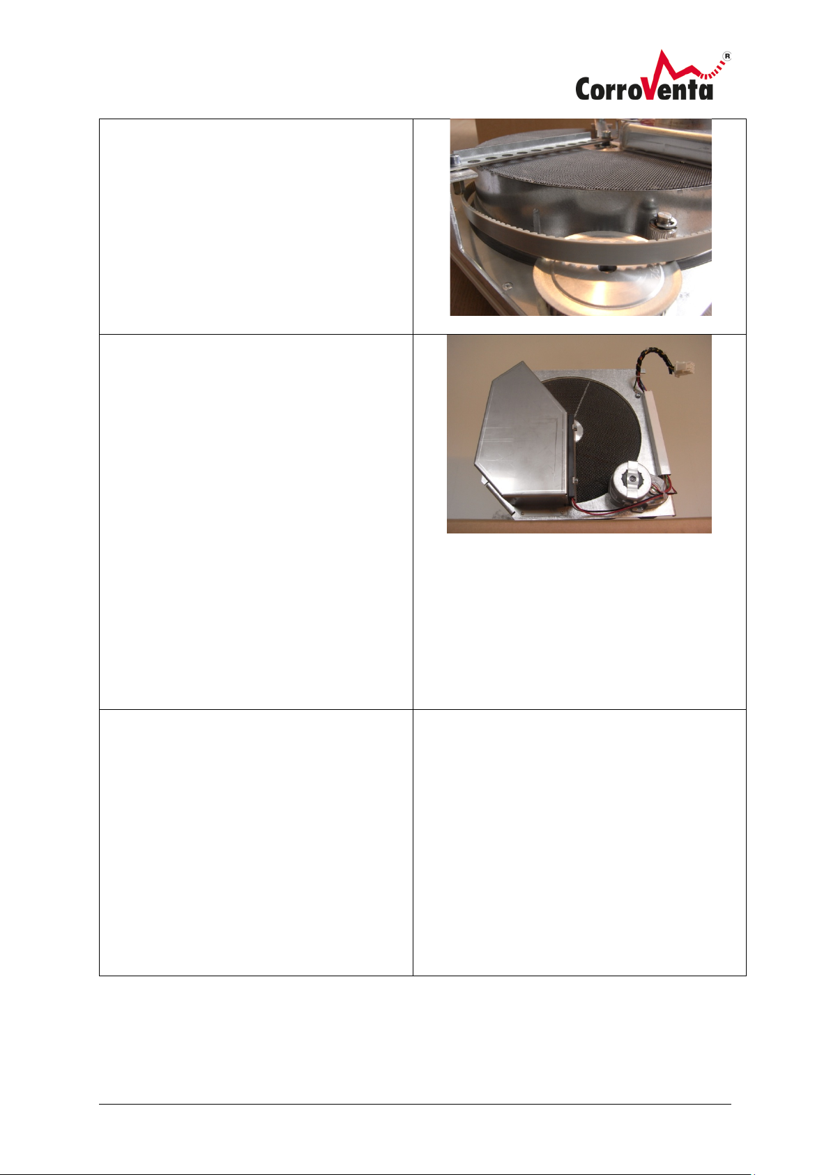
4. Press the tensioning wheel backward
on the rotor unit and slide the belt off
5. Note! Always use a suitable protective
6. Assemble the drier in reverse order
the wheel so that the rotor can rotate
freely.
mask when cleaning the rotor and
perform the work in a suitable location
outdoors.
Carefully blow clean the inside of the
rotor using compressed air. Hold the
nozzle about 15 cm from the rotor and
start blowing from the heat shield side
of the rotor. In this way, the air will
flow through the rotor in the opposite
direction to normal. This prevents more
dirt from getting stuck inside.
When you later clean from the other
direction, do not blow air into the heat
shield, otherwise dirt will accumulate
inside. Only blow on the rotor where
the opposite side is free and
unobstructed.
when the rotor has been cleaned:
• Install the belt.
• Carefully lower the rotor unit into
the machine.
• Reinstall the wet air hose. Reinstall
the bracket on A2ES and reconnect
the hose on the nipple on the heat
shield of the rotor unit.
• When the cover is in place and its
four screws installed, ensure that
the tag washers, one at each end of
the machine are also installed.
Page 18

© Corroventa Ltd.
2017.05
16 (17)
Accessories and consumables
Fault symptom
Probable cause
Actions
Premises not
Depending on the situation,
Perform fault tracing as follows until the
The drier does not
The drier is set to Hyg.
Connect a hygrostat, or switch to Man.
The rotor rotates
outlet) or not at all.
Fault with rotor motor or
Contact the dealer for repair.
No air flow, low air
Fault with fan or fan
Contact the dealer for repair.
Part number
Designation
01100
Hygrostat, HR1-5
1002720
Process air filter
The following parts are available as accessories and consumables for CTR A:
Fault tracing
dehumidified/low
capacity.
start.
anti-clockwise (seen
through the dry air
the cause of the problem
could be incorrect
installation, e.g. because of
obstructed wet air hose,
clogged filter, incorrect
settings on the machine or
machine fault.
without the hygrostat
connected.
motor capacitor.
problem has been identified:
Check the installation - check that the wet
air hose is not obstructed, that the dry air
damper is in the correct position and that
the hose used on the dry air side is not
trapped or clogged. Ensure that the air flow
is correct.
If the air flow is weak, check the process air
filter and replace if necessary.
mode.
flow
capacitor.
Page 19
© Corroventa Ltd.
2017.05
17 (17)
Technical data
Dry air volume (m3/h)
220/170
Drying capacity at 20°C, 60 % RH MAX mode (litres/day)
16/12
Ø dry air outlet (mm)
1 x 100, 2 x 50
Ø wet air outlet (mm)
80
Sound level, normal operation dBA (3 m)
approx. 50-55 *
Voltage
230 VAC/50 Hz
Rated output (W)
1250
Height x width x length (mm)
430 x 295 x 415
Weight, kg 16
Dry air volume (m3/h)
330/210
Drying capacity at 20°C, 60 % RH MAX mode (litres/day)
25/17
Ø dry air outlet (mm)
2 x 100, 2 x 50
Ø wet air outlet (mm)
80
Sound level, normal operation dBA (3 m)
approx. 50-55 *
Voltage
230 VAC/50 Hz
Rated output (W)
1550
Height x width x length (mm)
430 x 295 x 475
Weight, kg 18
CTR A2
*Sound level varies depending on the installation.
CTR A4
*Sound level varies depending on the installation.
Page 20
DO YOU HAVE ANY QUESTIONS OR DO YOU NEED OUR SUPPORT?
Please visit www.corroventa.com or call us at +44 (0)161-244 95 23 and speak to an expert.
We have the knowledge and the equipment to find a solution as eciently as possible.
Corroventa develops, manufactures, sells and hires out high quality products for
dealing with water damage, moisture, odours and radon. We are market leaders
and specialise in innovation within the industry. Our products are compact, eective, ergonomic and energy ecient. In emergency situations and during flooding,
Corroventa’s customers have access to one of the largest rental parks in Europe.
We have sales oces and machine depots in several locations throughout Europe.
All our manufacturing takes place in Bankeryd, Sweden.
www.corroventa.com
Unit 29, Irlam Business Centre, Irlam, Manchester,
CORROVENTA LTD
England, M44 6GP • Tel +44 (0) 161-2449523
www.corroventa.com
 Loading...