

Page 1
When selecting the site for your pool, take into account city
by-laws regarding fences and utilities laws pertaining to
electrical cables, as well as the landscaping which you are
planning once the pool is installed.
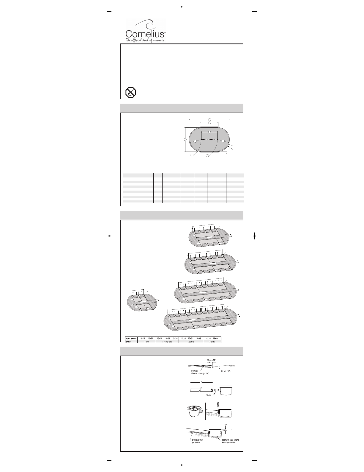
1) Drive a stake into the ground at points A and B respecting the
distance of the straight section between those two points (A-B).
2) Draw two half circles respecting the radius (R).
3) Join the two half circles with straight lines respecting the
width between these two lines (D).
4) Verify that the total length is consistent. (E)
5) Add 15cm (6”) wide trenches on each side, respecting the
lenght (F), to leave room for the stays.
6) Remove all grass from the area which you have just outlined.
Dear Customer
Congratulations! You have purchased a pool of superior quality and durability. To achieve the best possible results, follow
the instructions carefully. Failure to follow the installation procedures may result in damage to your pool or proper ty and
void your warranty. We recommend that you make a preliminar y study of the instructions booklet to familiarize yourself
with the different parts of your pool. Make sure that you understand each step thoroughly before you begin assembling.
We wish you a most pleasant and refreshing summer.
WARNING: Be sure you have read and understood the “Safety Information”
sheets before you begin your pool installation.
WARNING: For your safety, your pool is not designed for diving and/or jumping head first.
Please do not dive. Diving may result in permanent injury or death.
SITE PREPARATION
1
SITE LEVELLING AND EXCAVATION
2
Dig a hole 30 cm (12") wide by approximately 25 cm (10") deep
in the center of the circumference.
From the center hole to the projected location of the pool motor,
dig a 15 cm (6") wide trench. Place the removed soil aside to
be used later to cover the hose.
Bottom Drain Assembly
Place teflon around the threaded plug. Screw in drain holes
using large pliers. Glue the connector in the appropriate
opening.Glue connector in the appropriate opening.
Take one of the two rubber rings and adjust it to the top of the
drain, aligning the holes carefully. Secure with strips of adhesive
tape to prevent sand from penetrating inside the holes once the
drain has been installed.
Secure one end of the long black or white hose inside the drain
spout. First apply glue on the drain spout and inside the drain
end, then secure with one or two collars.
Cut the hose so that it ends with the stone dust (or sand).
Measure the pool radius from the center of the drain, then add
15 cm (6").
Place the assembled bottom drain in the hole so that it is
approximately 1.3cm (1/2") higher than the surface soil. Bury
the hose, levelling the
drain as much as possible. Compact the
soil, using your feet and a tampering tool as well.
Mix three (3) shovels of stone or sand dust with one half shovel
of pure cement, adding a small quantity of water, then pour the
cement around the drain until it reaches 1.3 cm (1/2") from the
top.
BOTTOM DRAIN ASSEMBLY (if applicable)
3
Chart 1.1 - Grass removal area (Figure 1.1)
1,68m (5'6")
1,68m (5'6")
2,13m (7')
2,13m (7')
2,44m (8')
2,44m (8')
2,44m (8')
2,90m (9'-6")
2,90m (9'-6")
2,90m (9'-6")
3,35m (11')
3,35m (11')
4,27m (14')
4,27m (14')
4,88m (16')
4,88m (16')
4,88m (16')
5,79m (19')
5,79m (19')
5,79m (19')
5,03m (16'-5 3/4")
6,69m (21'-11")
5,48m (17'-11 3/4")
7,14m (23'-5")
6,30m (20'-8")
7,96m (26'-1 1/2")
9,64m (31'-7 1/4")
10,29m (33'-9")
11,95m (39'-2 1/2")
13,63m (44
'-8 1/2")
1,66m (5'-5 1/2")
3,33m (10'-11")
1,66m (5'-5 1/2")
3,33m (10'-11")
1,66m (5'-5 1/2")
3,33m (10'-11")
4,99m (16'-4 1/2")
4,99m (16'-4 1/2")
6,66m (21'-10")
8,32m (27'-3 1/2")
MODELTRUE POOL SIZE
DISTANCE (A-B)
RADIUS (R) WIDTH (D) TOTAL LENGHT (E) CORRIDOR (F)
10'x16' 1,67m (5'-5 3/4")
10'x21' 3,33m (10'-11")
13'x18' 1,18m (3'-10 1/2")
13'x23' 2,84m (9'-3 3/4")
15'x20' 1,42m (4'-7 3/4")
15'x26' 3,07m (10'-1")
15'x31' 4,75m (15'-7")
18'x33' 4,53m (14'-10 1/4")
18'x38' 6,19m (20'-3 1/2")
18'x44' 7,87m (25'-9
3/4")
3,05 x 4,72 m (10' x 15' 5-3/4")
3,05 x 6,38 m (10' x 20' 11-1/8")
3,96 x 5,17 m (13' x 16' 11-3/4")
3,96 x 6,83 m (13' x 22' 5")
4,57 x 5,99 m (15' x 19' 8")
4,57 x 7,65 m (15' x 25' 1-3/8")
4,57 x 9,33 m (15' x 30' 7-1/4")
5,44 x 9,98 m (17' 10" x 32' 9")
5,44 x 11,64 m (17' 10" x 38' 2-3/8")
5,44 x 13,32 m (17' 10" x 43' 8-1/2")
A
B
A-B
R
R
D
15cm (6”)
E
F
POOL WALL
AREA TO OUTLINE
Figure 1.1
SITE LEVELLING
For an oval pool, the bottom must absolutely be levelled, using a
carpenter's level and a straight plank. Eliminate any protrusions.
Ensure that the surface is free of debris such as rocks, wood,
etc.
TRENCHES FOR BUTTRESS ASSEMBLIES
1) Dig trenches to a depth equal to the sum of the thickness of
the patio blocks (2” thick slabs recommen ded) and the
thickness of the butress assembly beam 8cm (3 1/4”). (Refer to
illustrations for trenches layout details).
2) Make sure trenches are smooth and leveled without
compacting them.
3) Place and level patio blocks into trenches. Make sure that the
top of the slabs is at a depth of 8cm (3 1/4”). Top of framework
must be level with pool area.
141" - 358cm
22-3/4"
22-3/4"
10"
10"
10"
25cm
25cm
25cm
25cm
25cm
141" - 358cm
22-3/4"
22-3/4"
10"
10"
10"
25cm
25cm
25cm
25cm
25cm
FOR
10x21: 38" (97cm)
13x23: 62" (157cm)
15x26: 110" (279cm)
22-3/4"
22-3/4"
58cm
58cm
58cm
10"
10"
3-1/4" - 8cm
DEEP
15cm
31"
79cm
22-3/4"
22-3/4"
58cm
58cm
58cm
10"
10"
3-1/4" - 8cm
DEEP
15cm
122cm
6"
31"
79cm
122cm
6"
15cm
6"
58cm
141" - 358cm
48"
6"
15cm
43cm
58cm
141" - 358cm
48"
43cm
17"
R
10"
10"
10"
22-3/4"
22-3/4"
75-1/2" - 192cm
3-1/4" - 8cm
DEEP
15cm
25cm
25cm
25cm
6"
15cm
31"
79cm
FOR:
10x16: 38" (97cm)
13x18: 62" (157cm)
15x20: 87" (221cm)
10"
10"
10"
22-3/4"
22-3/4"
75-1/2" - 192cm
75-1/2" - 192cm
3-1/4" - 8cm
DEEP
15cm
25cm
25cm
25cm
R
6"
15cm
6"
43cm
31"
79cm
58cm
58cm
17"
48"
122cm
15cm
3-1/4" - 8cm
DEEP
122cm
6"
79cm
15cm
FOR:
15x31: 110" (279cm)
18x33: 132" (335cm)
3-1/4" - 8cm
DEEP
122cm
6"
79cm
17"
31"
206-1/2" - 525cm
17"
31"
48"
R
6"
15cm
R
43cm
206-1/2" - 525cm
22-3/4"
22-3/4"
22-3/4"
58cm
22-3/4"
58cm
10"
10"
10"
10"
10"
25cm
25cm
25cm
25cm
25cm
25cm
206-1/2" - 525cm
22-3/4"
58cm
22-3/4"
22-3/4"
22-3/4"
58cm
22-3/4"
58cm
10"
10"
10"
10"
10"
25cm
25cm
25cm
25cm
25cm
25cm
10"
10"
22-3/4"
22-3/4"
58cm
58cm
58cm
25cm
10"
10"
58cm
22-3/4"
58cm
58cm
25cm
58cm
15cm
3-1/4" - 8cm
DEEP
122cm
6"
79cm
15cm
FOR:
18x38: 132" (335cm)
3-1/4" - 8cm
DEEP
122cm
6"
79cm
17"
31"
206-1/2" - 525cm
17"
31"
48"
R
6"
15cm
R
43cm
272" - 691cm
22-3/4"
22-3/4"
22-3/4"
58cm
22-3/4"
58cm
10"
10"
10"
10"
10"
25cm
25cm
25cm
25cm
25cm
25cm
22-3/4"
58cm
22-3/4"
22-3/4"
10"
10"
10"
25cm
25cm
25cm
22-3/4"
58cm
10"
25cm
22-3/4"
58cm
10"
25cm
25cm
10"
10"
22-3/4"
22-3/4"
58cm
58cm
58cm
25cm
10"
10"
58cm
22-3/4"
58cm
58cm
25cm
58cm
15cm
3-1/4" - 8cm
DEEP
122cm
6"
79cm
15cm
FOR:
18x44: 132" (335cm)
3-1/4" - 8cm
DEEP
122cm
6"
79cm
17"
31"
206-1/2" - 525cm
17"
31"
48"
R
6"
15cm
R
43cm
337-1/2" - 857cm
22-3/4"
22-3/4"
22-3/4"
58cm
22-3/4"
58cm
10"
10"
10"
10"
10"
25cm
25cm
25cm
25cm
25cm
25cm
22-3/4"
58cm
22-3/4"
22-3/4"
10"
10"
10"
25cm
25cm
25cm
22-3/4"
58cm
10"
25cm
22-3/4"
58cm
10"
25cm
22-3/4"
58cm
10"
25cm
22-3/4"
58cm
10"
25cm
25cm
10"
10"
22-3/4"
22-3/4"
58cm
58cm
58cm
25cm
10"
10"
58cm
22-3/4"
58cm
58cm
25cm
58cm
Chart: Sand quantity
ASSEMBLY INSTRUCTIONS
OVAL POOLS
MODELS: CAPRI / ZEPHYR / BORA / BRISA
25x38-Trevi Capri OVALE_V2_25-38-Trevi 209-218 OVALE.qxd 08-02-12 10:11 Page 6
Page 2
1) Dump the sand.
2) Choose the filter location beside a round section (never a straight
section). The starting point will be at that location so that the
skimmer and retur n holes are as close as possible to the filtration
system.
3) Before uncoiling the wall, make sure the pre-punched holes for
the skimmer and pump return are at the top and facing the planned
location of your filter.
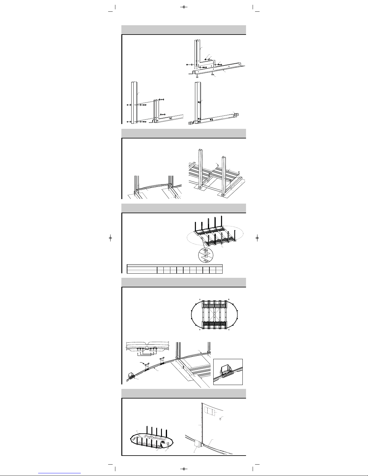
SRTAIGHT SECTION BUTTRESS ASSEMBLY
4
1) Refer to Illustration 4.1. To assemble, join splice brackets
(R) to the horizontal beam (Q) using the bolt 1/2 "X 3" X #13
(12.7 mm x 76.2 mm) (U), nuts (UU ) and washers (V).
Remember to insert a spacer (T) inside the beams aligned to
each bolt.
2) Refer to Illustration 4.2. Assemble the post using bolts
1/2" X 3" X #13 (12,7 mm X 76,2 mm) (U), nuts (UU) and
washers (V). Remember to insert a spacer (T) and two washers
(V) inside the beam aligned to each bolt.
3) Refer to Illustration 4.3. Cover the bolt heads with bolt
caps (W) and insert the styrofoam caps (X) at both ends of foot
beam.
1/2” BOLT CAP COVER
STYROFOAM CAP
SPLICE BRACKET
WASHER 1/2”
NUT 1/2”
FOOT BEAM
SPOOL SLEEVE
BOLT 1/2” X 3”
BUTTRESS POST
Illustration 4.1
Illustration 4.3
Illustration 4.2
1) Position the buttress pillars assembled in Step 4 on the patio
blocks in the trenches previously dug.
2) Refer to Illustration 5.1 : Once the buttress pillars are
placed in the trenches, assemble the straight sections bottom
tracks (J) between the pillars on the foot beams.
3) Refer to Illustration 5.2 : Fix the pressure plates between
foot beams using 4 standard screws #14.
BOTTOM TRACK
STRAIGHT SECTION
BOTTOM TRACKS (STRAIGHT) AND PRESSURE PLATES
5
STANDARD
SCREW # 14
PRESSURE PLATE
Illustration 5.2
Illustration 5.1
1) Study illustrations and chart carefully. You are now ready to
assemble the metallic tension straps. Refer to indications on the
chart for the exact number of tension straps and sections per
straps according to their respective pool size.
2) Refer to Illustration 6.1: If there is more than one metallic
strap per tension strap rows, assemble the straps together using 4
bolts and nuts (BB) 1/4" #20 X 5/8" (6,35 mm X 15,88 mm),
taking care of placing the bolt head on top.
3) Attach the assembled tension straps to foot beams on both
sides, using 4 standard screws #14.
POOL SIZE 10x16 10x21 13x18 13x23 15x20 15x26 15x31 18x33 18x38 18x44
TENSION STRAPS QUANTITY (TOTAL) 356 10 6 15 21 21 27 33
ROWS TO ASSEMBLE 3 5 35257 7 9 11
STRAPS PER ROW 1 1 22333 3 3 3
Chart
TENSION STRAPS ASSEMLBY
6
BUTTRESS ASSEMBLY
Illustration 6.1
Start with round sections, refer to illustration 7.1 :
Place the end of the first round section bottom track on the foot
beam of the last pillar of the straight section. At the other end,
place the first foot plate of the round section.
Round section, refer to Illustration 7.1 and 7.2 :
Using the round section bottom tracks and the foot plates, start
with the first plate of the round section. Repeat this procedure
until the half circle is completed.
Lock the track to the right pool
diameter by snapping the key on the corresponding posts.
Refer to Illustration 7.3. :
Before going to next step, make sure that the centre of the pool
is properly squared and metallic tension straps are stretched.
ROUND SECTIONS BOTTOM TRACKS ASSEMBLY
7
WALL INSTALLATION
8
SAND
PLANKS
SUPPORT
BAR
SAND
BAR
SUPPORT
PLANKS
JOINER PLATE
BOTTOM TRACK
PUMP RETURN
HOLE
WALL
SKIMMER HOLE
1ST TRACK
ROUND SECTION
1
ST
FOOT PLATE
ROUND SECTION
BOTTOM TRACK
STRAIGHT SECTION
Illustration 7.3
Illustration 7.1
Illustration 7.2
25x38-Trevi Capri OVALE_V2_25-38-Trevi 209-218 OVALE.qxd 08-02-12 10:11 Page 7
Key
Page 3

Before pulling the liner up against the wall, insert a vacuum
cleaner hose down into the pump return hole to approximately
15 cm (6") from the ground.
Maintain the hose in place with adhesive tape. Don't forget to
block the skimmer hole with adhesive tape to prevent air from
leaking in.
Place the unfolded liner in the center of the pool area at right
angles with the skimmer hole. Make sure you wear light, flatsoled shoes to walk on the sand as the slightest heel mark could
be visible once the pool is filled.
Carefully unfold the liner, bringing the bottom-sidewall seam
close to the wall base. Make sure that the side with the
protruding seams faces downward or that the patterned side
faces upward.
Lift up a section of the liner over the top of the wall leaving a 10
cm to 15 cm (4" to 6") fringe outside the wall. Secure the liner
with a plastic coupler. Install the resine stabiliser strack on the
wall then install the joiner plates on top of each upright.
At this point, the liner may be too tight, making it difficult to
drape the overlap or, on the contrary, too loose. In such cases,
you will have to redistribute the tension in the liner by remo-ving
some of the couplers and readjusting the liner.
Installation detail of the u-bead liner.
Hang the liner on the top of the wall and install thesquare
stabiliser to secure.
Start the vacuum cleaner to allow the liner to adhere to the wall
and check for excess tension at the bottom or for wrinkles.
Adjust the liner by removing couplers if needed, to lift or lower it
in order to ensure a perfect fit.
Fill the pool up to the base of the wall before stopping and
removing the vacuum cleaner.
PUMP RETURN FITTING
After you remove the vacuum cleaner, you may install the return
fitting. Place the return fitting ring against the liner and adjust it
so that it is perfectly aligned with the hole in the wall.
When the ring is properly positioned and secured, cut the liner in
the middle of the ring. Insert the return fitting from the inside,
placing the first gasket between the return fitting and the liner
and the second between the wall and the liner. Then tighten the
outside ring with large pliers, taking care not to crease the liner.
BOTTOM DRAIN (optional)
Find the holes through the middle of the liner and screw the ring
and gasket in against the liner before cutting the liner in the
middle of the ring, then screw on the drain cover.
VINYL LINER INSTALLATION
10
LINER
RESINE
STABILISER
TRACK
WALL
PLASTIC
COUPLER
(SOLD SEPARATELY)
LINER
WALL
TRACK
WALL
You can now spread approximately 10 cm (4") of compacting
sand all around the inside base of the wall in order to protect the
liner from the cutting edges of the bottom wall tracks and the
stone dust (if applicable). Or install a prefabricated cove, if
available.
SAND BASE FINISHING
Level finishing sand one last time. Make sure that any sharp
stones, debris or roots have been removed from the surface. For
better protection, spray sand with water and pack it once more
until the base is nicely even.
SAND BASE FINISHING
9
WALL INSTALLATION (continued)
8
LINER
WALL
30 cm (12")
10 cm (4")
SAND COVE
(or PREFAB COVE)
BOTTOM
TRACK
Begin inserting the wall into the bottom wall tracks in the middle
of a joiner plate. At first, the wall is kept in place with one or two
support bars (or extra persons). One person uncoils the wall on
a beam or a plank, while a second person inserts it in the bottom
wall tracks. Do not uncoil more than 3 m (10') of wall before you
install a support bar to reinforce the structure.
Once the wall is completely uncoiled, you may find that it is too
long or that both ends do not meet by a few centimetres. If such
is the case, you must gently push the wall in or out. If this does
not work, roll up the wall again, realign the grooves and uncoil
the wall again. If the spread is too wide, measure the wall and
check it against the following chart.
When you prepare to join the ends of the wall, make sure the end
that is reinforced by the fold is inside the circle, facing the liner
and that the other end faces outward (Illustration 8.1).
When the wall joint is secured, install the round stabilisers on top
of it.
IMPORTANT: Due to the enormous
pressure exerted by the water on the
steel wall, it is absolutely essential that
all the bolts are screwed in tigh-tly and
no hole is left open. All bolt heads
must be inside with washer and nut
outside. Cover all bolt heads with
heavy fabric tape.
MODEL 10x16 10x21 13x18 13x23 15x20 15x26 15x31 18x33 18x38 18x44
42' 4-3/4" 53' 3-3/4" 48' 11" 59' 8" 56' 6" 67' 5" 78' 5" 86' 96' 11" 107' 11-1/2"
(12,92m) (16,25m) (19,91m) (18,24m) (17,22m) (20,55m) (23,90m) (26,21m) (29,54m) (32,91m)
ACTUAL LENGHT
OF THE WALL
Chart
Illustration 8.1
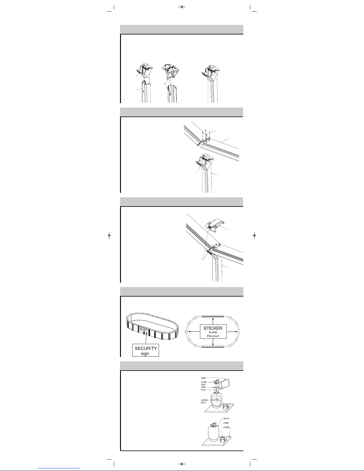
Clip the uprights to the bottom joiner plates.
Make sure the post is well snaped into the bottom plate.
BUTTRESS POST INSTALLATION
11
UPRIGHT
BOTTOM PLATE
25x38-Trevi Capri OVALE_V2_25-38-Trevi 209-218 OVALE.qxd 08-02-12 10:11 Page 8
Page 4
Note: See 'Safety Information" Manual, Page 1.
As described in the manual, all components of the filtration
system should be placed to prevent a child to climb on top and
get access to the pool.
Using a little bit of stone dust (or sand), place at level a patio
stone 61 cm x 76 cm (24" x 30") before installing the motor and
filter
Position the motor on the stone and insert the two nozzles to
connect the hoses.
Then, install the filter tank. Adjust the lateral assembly pro-perly
in its channel.
It is sometimes necessary to install the laterals.
Patch the center hole of the lateral assembly using the plug to
allow filtering sand to flow into the tank.
Remove the plug. Install the joint in the cavity and secure the
filter head by placing the back wash position on opposite side of
the pool.
Position the Safety procedures panel on the outside of the pool.
This panel must be at the most visible place from the yard on
your pool.
Place the four (4) safety stickers inside the pool in a way that it’s
seen from any entry point of the swimmer (See positionning
drawing).
SECURITY SIGNS INSTALLATION
15
SEAT CAP INSTALLATION
14
Clip the top plate into the upright.
Make sure the T shaped key is well align in the upright
front hole.
Make sure the top plate is well snaped into the post.
BUTTRESS POST TOP PLATE (STRAIGHT SECTIONS)
12
TOP SEAT INSTALLATION
13
Place the top seat on the upper side of the upright.
Align the holes on top seat with the right pool size on the
top plate.
Secure the top seat with two (4) screws.
Snap the seat cap stating out side the top seat.
Clip the front nose of the seat in side the top seat.
FILTRATION SYSTEM ASSEMBLY
16
UPRIGHT
TOP PLATE
KEY
TOP PLATE
UPRIGHT
SCREW
TOP SEAT
SEAT CAP
UPRIGHT
FIXE THE FRONT
HOOK FIRST
25x38-Trevi Capri OVALE_V2_25-38-Trevi 209-218 OVALE.qxd 08-02-12 10:11 Page 9
Page 5
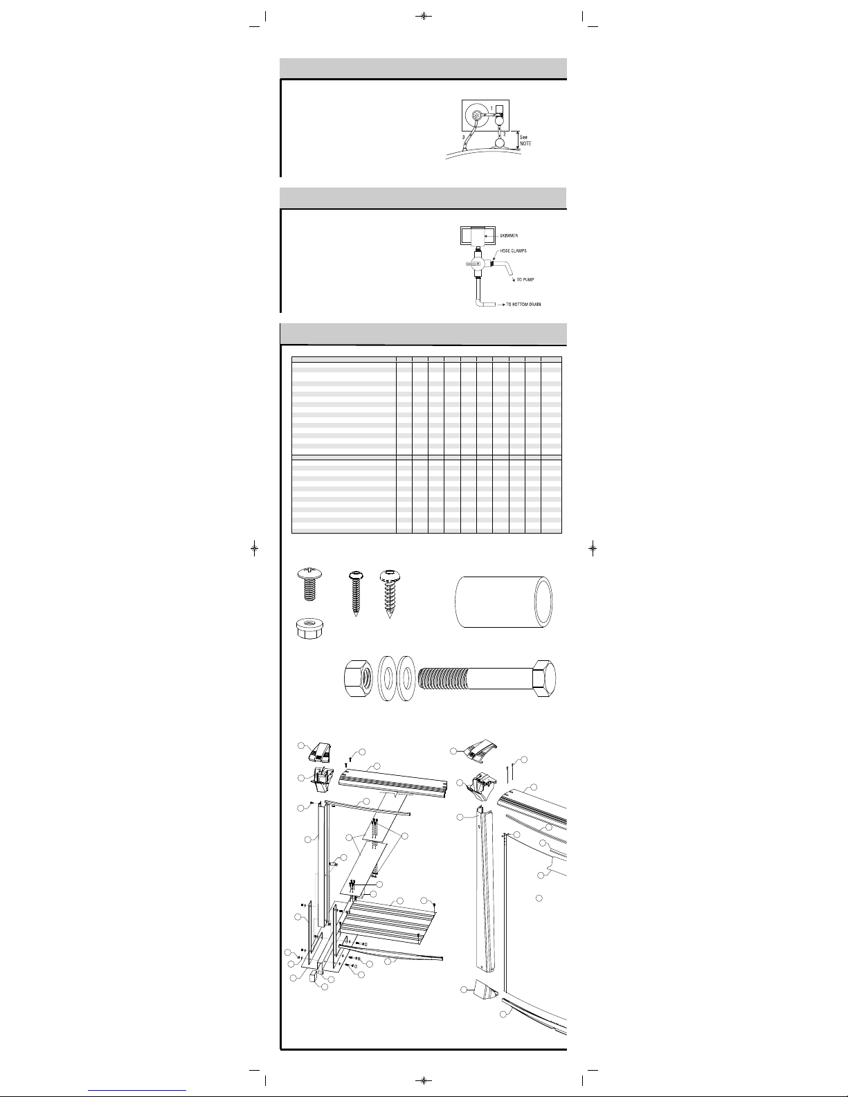
PARTS LIST
18
Insert threaded nozzles, if applicable, in order to be able to screw
the valve in the skimmer.
Connect the drain hose to the bottom nozzle. Connect the motor
hose to the side nozzle.
The threads on all threaded nozzles must be covered with teflon
tape prior to installing in order to prevent water leaks. Teflon is
applied to the threads as follows: little or none on the first few
threads (to facilitate introduction) and several layers toward the
end threads (for better watertightness).
DRAIN VALVE ASSEMBLY (if applicable)
17
Install necessary nozzles, then connect hoses using collars.
1. The first hose runs from the top of the pump to the side of the
filter head;
2. The second one goes from the pump to the skimmer (or to the
bottom drain valve);
3. The third goes from the front of the filter head to the water
return or from the front of the chlorinator to the water return.
A back wash hose may be placed behind the filter head.
If there is a chlorinator and/or heat pump, they must be
assembled at the filter exit.
FILTRATION SYSTEM ASSEMBLY
16
ITEMDESCRIPTION 10x16 10x2113x18 13x23 15x20 15x26 15x3118x33 18x38 18x44
Number of curved section
8 8 10 10 12 12 12 14 14 14
Number of straight section
4 8 4 8 4 8121216 20
POOL WALL (finished lenght, inch)
42' 4-3/4"
(12,92m)
53' 3-3/4"
(16,25m)
48' 11"
(19,91m)
59' 8"
(18,24m)
56' 6"
(17,22m)
67' 5"
(20,55m)
78' 5"
(23,90m)
86'
(26,21m)
96' 11"
(29,54m)
107' 11-1/2"
(32,91m)
BOLT & NUT FOR 52" (OR 54") WALL
25 (29) 25 (29) 25 (29) 25
(29) 25 (29) 25 (29) 25 (29) 25 (29) 25 (29) 25 (29)
POOL LINER
111111111 1
PLASTIC COUPLER (SOLD SEPARATELY)
111111111 1
TOP SEAT - ROUND SECTIONS
8 8 10 10 12 12 12 14 14 14
TOP SEAT- STRAIGHT SECTIONS
4
8 4 8 4 8121216 20
FOOT PLATE
6 6 8 8 10 10 10 12 12 12
UPRIGHT 52'' or UPRIGHT 54''
6 6 8 8 10 10 10 12 12 12
TOP PLATE ROUND SECTION
SEAT CAP
BTM TRACK - ROUND SECTIONS
446 6 8 8 8 10 10 10
BTM TRACK - STRAIGHT SECTIONS
4 8 4 8 4 8121216 20
TOP TRACK - ROUND SECTIONS
8 8 10 10 12 12 12 14
14 14
TOP TRACK - STRAIGHT SECTIONS
4 8 4 8 4 8121216 20
BUTTR
ESS ASSEMBLY
BUTTRESS POST
61061061014 14 18 22
TOP PLATE OVALE SECTION
61061061014 14 18 22
FOOT BEAM
61061061014 14 18 22
SPLICE BRACKET
12 20 12 20 12 20 28 28 36 44
PRESSURE PLATE
4 8 4 8 4 8121216 20
SPOO
L SLEEVE
244024402440565672 88
BOLT 1/2" X 3" X #13 (12,7 mm X 76,2 mm)
244024402440565672 88
NUT 1/2" (12,7 mm)
244024402440565672 88
WASHER 1/2" (12,7 mm)
72 120 72 120 72 120 168 168 216 264
BOLT CAP COVER
244024402440565672 88
FOOT BEAM STYROFOAM CAP
12 20 12 2
012202828
36 44
TENS
ION STRAP
3 5 6 10 6 15 21 21 27 33
1/4" #20 X 5/8" (6,35 mm X 15,88 mm) SCREW & FLANGE NUT
12 20 2440565672 88
STANDARD SCREW ( SCREW #14 , 1" LENGHT)
AA
BB
DD
CC
A
B
C
D
E
F
G
J
K
L
O
P
Q
R
S
T
U
UU
V
W
X
Y
BB
Z
6 6 8 8 10 10 10 12212 12
12 16 14 18 16 20 24 26 30 34
100
156 108 164 116 172 228 236 292 348
6
10 6 10 6 10 14 14 18 22
A
C
U
W
T
X
E
DD
O
Z
G
J
Q
V
B
Z
AA
L
S
T
Z
R
F
D
UU
P
Y
X
Z
BB
K
BB
CC
F
Z
BB
M
Z
T
U
UU
V
25x38-Trevi Capri OVALE_V2_25-38-Trevi 209-218 OVALE.qxd 08-02-12 10:11 Page 10
 Loading...