

Cornelius WM600, CM600 Installation & Owner's Manual
IMI CORNELIUS INC g One Cornelius Place g Anoka, MN 55303-6234
Telephone (800) 238-3600 Facsimile (763) 422-3246
Installation/Owner’s Manual
ICE MAKER
(WM600 AND CM600)
IMPORTANT:
TO THE INSTALLER.
It is the responsibility of the Installer to
ensure that the water supply to the Ice
Maker is provided with protection against
backflow by an air gap as defined in
ANSI/ASME A112. 1.2-1979; or an approved
vacuum breaker or other such method as
proved effective by test.
Water pipe connections and fixtures
directly connected to a potable water
supply shall be sized, installed, and
maintained according to Federal, State,
and Local laws.
Part No. 630460082
March 3, 2003
Revision: B
THIS DOCUMENT CONTAINS IMPORTANT INFORMATION
This Manual must be read and understood before installing or operating this equipment
IMI CORNELIUS INC; 1998–2003
PRINTED IN U.S.A

TABLE OF CONTENTS
SPECIIFICATIONS 3. . . . . . . . . . . . . . . . . . . . . . . . . . . . . . . . . . . . . . . . . . . . . . . . . . . . . . . . .
DESCRIPTION 3. . . . . . . . . . . . . . . . . . . . . . . . . . . . . . . . . . . . . . . . . . . . . . . . . . . . . . . . . . . .
INSTALLATION INSTRUCTIONS 3. . . . . . . . . . . . . . . . . . . . . . . . . . . . . . . . . . . . . . . . . . . .
REMOVE ICE MAKER FROM CARTON: 3. . . . . . . . . . . . . . . . . . . . . . . . . . . . . . . . .
CABINET REMOVAL 3. . . . . . . . . . . . . . . . . . . . . . . . . . . . . . . . . . . . . . . . . . . . . . . . . . .
PREPARATION OF INSTALLATION SITE 3. . . . . . . . . . . . . . . . . . . . . . . . . . . . . . . .
WATER INLET HOOK–UP: 4. . . . . . . . . . . . . . . . . . . . . . . . . . . . . . . . . . . . . . . . . . . . .
ELECTRICAL SUPPLY 4. . . . . . . . . . . . . . . . . . . . . . . . . . . . . . . . . . . . . . . . . . . . . . . . .
AUGER ENGAGEMENT 4. . . . . . . . . . . . . . . . . . . . . . . . . . . . . . . . . . . . . . . . . . . . . . .
INITIAL START UP, CHECKS AND ADJUSTMENT INSTRUCTIONS 5. . . . . . . . .
GUIDE TO SERVICE 6. . . . . . . . . . . . . . . . . . . . . . . . . . . . . . . . . . . . . . . . . . . . . . . . . . . . . . .
ICE MAKER CLEANING AND SANITIZING PROCEDURES 6. . . . . . . . . . . . . . . . .
MAINTENANCE 6. . . . . . . . . . . . . . . . . . . . . . . . . . . . . . . . . . . . . . . . . . . . . . . . . . . . . . .
MONTHLY 6. . . . . . . . . . . . . . . . . . . . . . . . . . . . . . . . . . . . . . . . . . . . . . . . . . . . . . . . . . .
QUARTERLY 6. . . . . . . . . . . . . . . . . . . . . . . . . . . . . . . . . . . . . . . . . . . . . . . . . . . . . . . .
SEMI-ANNUALLY 6. . . . . . . . . . . . . . . . . . . . . . . . . . . . . . . . . . . . . . . . . . . . . . . . . . . . .
WATER LEVEL CONTROL 7. . . . . . . . . . . . . . . . . . . . . . . . . . . . . . . . . . . . . . . . . . . . . .
WATER LEVEL CONTROL OPERATION 7. . . . . . . . . . . . . . . . . . . . . . . . . . . . . . . .
PURPOSE OF WATER LEVEL CONTROL 7. . . . . . . . . . . . . . . . . . . . . . . . . . . . . . .
TO REPLACE WATER LEVEL CONTROL 8. . . . . . . . . . . . . . . . . . . . . . . . . . . . . . .
TO REPLACE WATER LEVEL SAFETY SWITCH 8. . . . . . . . . . . . . . . . . . . . . . . . .
ICE LEVEL CONTROL 8. . . . . . . . . . . . . . . . . . . . . . . . . . . . . . . . . . . . . . . . . . . . . . . .
REFRIGERATION SYSTEMS 9. . . . . . . . . . . . . . . . . . . . . . . . . . . . . . . . . . . . . . . . . . . . . . .
Page
REFRIGERATION SYSTEM ADJUSTMENTS 9. . . . . . . . . . . . . . . . . . . . . . . . . . . . .
EXPANSION VALVE 9. . . . . . . . . . . . . . . . . . . . . . . . . . . . . . . . . . . . . . . . . . . . . . . . . .
ADJUSTMENT AND TROUBLESHOOTING 9. . . . . . . . . . . . . . . . . . . . . . . . . . . . . . .
ADJUSTMENT AND TROUBLESHOOTING 9. . . . . . . . . . . . . . . . . . . . . . . . . . . . . .
TEMPERATURE/PRESSURE CHART 10. . . . . . . . . . . . . . . . . . . . . . . . . . . . . . . . . . . . . . . .
CONDENSER MODULATING VALVE (WATER COOLED ONLY) 10. . . . . . . . . . . .
CONDENSER MODULATING VALVE REMOVAL 11. . . . . . . . . . . . . . . . . . . . . . . . . .
GEAR MOTOR 11. . . . . . . . . . . . . . . . . . . . . . . . . . . . . . . . . . . . . . . . . . . . . . . . . . . . . . . .
TROUBLESHOOTING 13. . . . . . . . . . . . . . . . . . . . . . . . . . . . . . . . . . . . . . . . . . . . . . . . . . . . . .
TROUBLESHOOTING GEAR MOTORS 13. . . . . . . . . . . . . . . . . . . . . . . . . . . . . . . . . .
THE GEARMOTOR WILL NOT RUN 13. . . . . . . . . . . . . . . . . . . . . . . . . . . . . . . . . . . . .
THE GEARMOTOR STARTS BUTS TRIPS REPEATEDLY ON THE
OVERLOAD PROTECTOR 13. . . . . . . . . . . . . . . . . . . . . . . . . . . . . . . . . . . . . . . . . . . . . .
THE MOTOR RUNS BUT OUTPUT SHAFT DOES NOT ROTATE 13. . . . . . . . . . . .
OVERLOAD CHECK: 13. . . . . . . . . . . . . . . . . . . . . . . . . . . . . . . . . . . . . . . . . . . . . . . . . . .
MOTOR CHECK: 13. . . . . . . . . . . . . . . . . . . . . . . . . . . . . . . . . . . . . . . . . . . . . . . . . . . . . .
INSTALLATION AND SHAFT SEAL REPLACEMENT 14. . . . . . . . . . . . . . . . . . . . . . .
AUGER & EXTRUDING HEAD REMOVAL 15. . . . . . . . . . . . . . . . . . . . . . . . . . . . . . . .
TO REPLACE BEARINGS 15. . . . . . . . . . . . . . . . . . . . . . . . . . . . . . . . . . . . . . . . . . . . . .
TROUBLESHOOTING COMPRESSOR 15. . . . . . . . . . . . . . . . . . . . . . . . . . . . . . . . . . .
i
630460082

TABLE OF CONTENTS (cont’d)
ELECTRICAL CHECKOUT 16. . . . . . . . . . . . . . . . . . . . . . . . . . . . . . . . . . . . . . . . . . . . . .
OVERLOAD CHECK 16. . . . . . . . . . . . . . . . . . . . . . . . . . . . . . . . . . . . . . . . . . . . . . . . . . .
COMPRESSOR CHECK 16. . . . . . . . . . . . . . . . . . . . . . . . . . . . . . . . . . . . . . . . . . . . . . . .
CAPACITOR CHECK 16. . . . . . . . . . . . . . . . . . . . . . . . . . . . . . . . . . . . . . . . . . . . . . . . . . .
SAFETY CONTROLS 17. . . . . . . . . . . . . . . . . . . . . . . . . . . . . . . . . . . . . . . . . . . . . . . . . .
GUIDE TO GOOD ICE 18. . . . . . . . . . . . . . . . . . . . . . . . . . . . . . . . . . . . . . . . . . . . . . . . . . . . . .
TROUBLESHOOTING CHART – ICEMAKER NOT OPERATING 19. . . . . . . . . . . . . . . .
WARRANTY 27. . . . . . . . . . . . . . . . . . . . . . . . . . . . . . . . . . . . . . . . . . . . . . . . . . . . . . . . . . . . . .
LIST OF FIGURES
FIGURE 2. AUGER ASSEMBLY 7. . . . . . . . . . . . . . . . . . . . . . . . . . . . . . . . . . . . . . . . .
FIGURE 3. ADJUSTMENT SCREW 10. . . . . . . . . . . . . . . . . . . . . . . . . . . . . . . . . . . . . .
FIGURE 4. OUTPUT SHAFT 13. . . . . . . . . . . . . . . . . . . . . . . . . . . . . . . . . . . . . . . . . . .
FIGURE 5. SHAFT SEAL REPLACEMENT 14. . . . . . . . . . . . . . . . . . . . . . . . . . . . . . .
FIGURE 6. EXTRUDING HEAD 14. . . . . . . . . . . . . . . . . . . . . . . . . . . . . . . . . . . . . . . . .
FIGURE 7. AUGER 14. . . . . . . . . . . . . . . . . . . . . . . . . . . . . . . . . . . . . . . . . . . . . . . . . . . .
FIGURE 8. UPPER NUT AND BEARING 15. . . . . . . . . . . . . . . . . . . . . . . . . . . . . . . . .
FIGURE 9. ELECTRICAL BOX 16. . . . . . . . . . . . . . . . . . . . . . . . . . . . . . . . . . . . . . . . . .
FIGURE 10. GEAR MOTOR THERMAL OVERLOAD 17. . . . . . . . . . . . . . . . . . . . . . .
FIGURE 11. TROUBLESHOOTING CHART 19. . . . . . . . . . . . . . . . . . . . . . . . . . . . . . .
FIGURE 14. MOUNTING TEMPLATE 26. . . . . . . . . . . . . . . . . . . . . . . . . . . . . . . . . . . .
Page
630460082
ii
SAFETY INFORMATION
Recognize Safety Information
This is the safety-alert symbol. When you see this
symbol on our machine or in this manual, be alert to
the potentially of personal injury.
Follow recommended precautions and safe operating
practices.
Understand Signal Words
A signal word - DANGER, WARNING, OR CAUTION
is used with the safety-alert symbol. DANGER identi-
fies the most serious hazards.
DANGER
Safety signs with signal word DANGER or WARNING
are typically near specific hazards.
General precautions are listed on CAUTION safety
signs. CAUTION also calls attention to safety messages in this manual.
WARNING
CAUTION
Follow Safety Instructions
Carefully read all safety messages in this manual and on your machine safety signs. Keep safety signs in
good condition. Replace missing or damaged safety signs. Learn how to operate the machine and how to
use the controls properly. Do not let anyone operate the machine without instructions. Keep your machine in
proper working condition. Unauthorized modifications to the machine may impair function and/or safety and
affect the machine life.
CAUTION: Very high discharges pressure is present in system. Quick disconnects on your
gages will minimize danger and loss of refrigerant.
CAUTION: Unit requires separate electrical line. See instruction manual for proper fuse
size.
WARNING: There must be adequate clearance around ice maker. Allow minimum 6” air
intake and 4” air exhaust for air exhaust and panel removal.
NOTE: Unit must be installed per local plumbing and electrical codes. See Installation manual for
unit requirements. Failure to do so may cause damage to unit, which would void unit warranty.
NOTE: Using any parts other than genuine factory manufactured parts relieves the manufacturer of all
liability.
NOTE: Manufacturer reserves the right to change specifications at any time.
1 630460082

THIS PAGE LEFT BLANK INTENTIONALLY
2630460082

SPECIIFICATIONS
Model WM (Wall Model) 600 and CM (Counter Model) 600
Compressor 3/4 H.P. (R404 Refrigerant)
Voltage 115 VAC, 60 Hz, Single Phase
Current Draw 16 Amps
Circuit Breaker or Fuse Size 20 Amp Maximum Time Delay
DESCRIPTION
Models WM600 and CM600 Ice Makers are self-contained wall mount and counter style Units which automatically make hard compressed-style ice and store it in a sealed hopper for sanitary dispensing.
INSTALLATION INSTRUCTIONS
IMPORTANT: An Everpure Model 9320–42 Systems IV Model DB900 ice maker quality water treatment
unit MUST BE INSTALLED in the water supply line to the Ice Maker. Failure to do so may result in poor
quality ice, low production output, and may cause premature failure of the Ice Maker evaporator and
void the extended evaporator warranty.
This Ice Maker is provided with a stainless–steel evaporator designed to last the life of the product.
But, some of the chemicals in treated and untreated water, specifically chlorine and sulphur (sulphide),
have the ability to attack stainless–steel and cause premature failure. An initial investment in proper
water treatment will pay for itself in increased production, quality, and long life of the product.
REMOVE ICE MAKER FROM CARTON:
1. Keep Unit in the upright position, remove carton and pallet from the Unit and inspect the unit for damage.
Upon inspection of the unit, if any damage is found, file a claim with the carrier immediately.
2. Locate the Startup Card either on the outside of the container or on the plastic liner. Fill in the proper information and send one copy to the factory and the other copy to the Distributor. The postage is prepaid.
CABINET REMOVAL
1. Unscrew and remove the front panels for electrical and start–up access.
2. Remove shipping tape from the storage hopper cover and the agitator in storage hopper.
PREPARATION OF INSTALLATION SITE
1. For maximum efficiency and ice output, select a location for your ice maker where it will not be exposed to
sunlight, excessive heat or reflected radiation (preferably in a room with a temperature of 70° F to 80° F).
The icemaker normally will not function properly in temperatures below 65° F. The area surrounding the ice
maker should be well ventilated. (Consult Figure ???? for proper airflow clearance). WM600 – Two (2)
mounting brackets are supplied for securing the Unit to a wall.
CM600 – Consult Figure 1B and 1C for dimensions for mounting the Unit to the counter. Note that the Unit
must be level for proper operation.
2. The Unit must be sealed to the counter. Locate the desired position for the Unit, then mark the outline
dimensions on the counter.
3 630460082

3. Apply a continuous bead of NSF listed silastic sealant (Dow 732 or equal) approximately 1/4–inch inside of
the Unit outline dimensions. Then, position the Unit on the counter within the outline dimensions. All excess
sealant must be wiped away immediately.
IMPORTANT: The WM600 with a full ice storage hopper weighs 450 pounds. Make sure that the
mounting surface is adequately reinforced to support this weight.
The mounting hole dimensions for the brackets are shown in Figure 1A. Use these dimensions to locate the Unit
at the desired height on the wall.
IMPORTANT: Provide support for the Unit until all eight (8)–mounting bolts are installed. Do not hang
the Unit from the top mounting angle bracket only while installing the lower angle.
W ATER INLET HOOK–UP:
1. Water Inlet – The fitting is a 1/4”–in. compression fitting located at the bottom of the Unit. Connect water
supply with a 1/4–inch or larger copper or flexible tubing.
2. Water Pressure – Unless otherwise specified, the Unit is designed to operate on a water pressures between 10 P.S.I. and 90 P.S.I. (NOTE: for pressures above 90 P.S.I; a water pressure regulator must
be installed).
3. Water Cooled Condensers – The inlet uses a 3/8–inch compression fitting. Use a separate 3/8–inch or
larger water line.
4. Filter Conditioners are recommended on supply lines to the Ice Makers. Never run the water supply to
the water cooled condenser through a Filter/Conditioner. It uses up the cartridge unnecessarily and a saturated cartridge can starve the Ice Maker causing premature component damage. Separate water supplies
are recommended.
WM600 – Connect a 1–1/4 inch IPS (or equal) drain line to the1–1/4 inch diameter P–trap at the lower
bottom of the Unit. The line must pitch downward to an open drain and must contain no traps or improper
drainage will result.
CM600 – Connect two (2) 3/4–inch IPS (or equal) drain lines to the 3/4–inch threaded drain connections at
the lower rear of the Unit. These lines must pitch downward to an open drain and must contain no traps or
improper drainage will result. For water–cooled Units, a third 3/4–inch FPT drain fitting is provided for the
condenser drain (see Figure 1B).
NOTE: The Unit must be installed per local plumbing codes.
ELECTRICAL SUPPLY
1. Power Access – Is provided by way of a 7/8–inch diameter hole located on the lower left side of the Unit.
Route incoming power in conduit, to the Ice Maker electrical control box. Make connections to wires provided in the control box and the ground lug/screw.
2. Fused Line – Should be a dedicated circuit checked and sized according to the electrical rating shown on
the Unit nameplate.
NOTE: The Unit must be installed per local electrical codes.
AUGER ENGAGEMENT
Be certain that the auger is fully engaged to the lower drive and that the extruding head is fully engaged to the
evaporator.
4630460082
INITIAL START UP, CHECKS AND ADJUSTMENT INSTRUCTIONS
NOTE: Do not start the Unit before completing the previous Installation steps.
Turn on the water supply and main power switch (located on top of the electrical box).
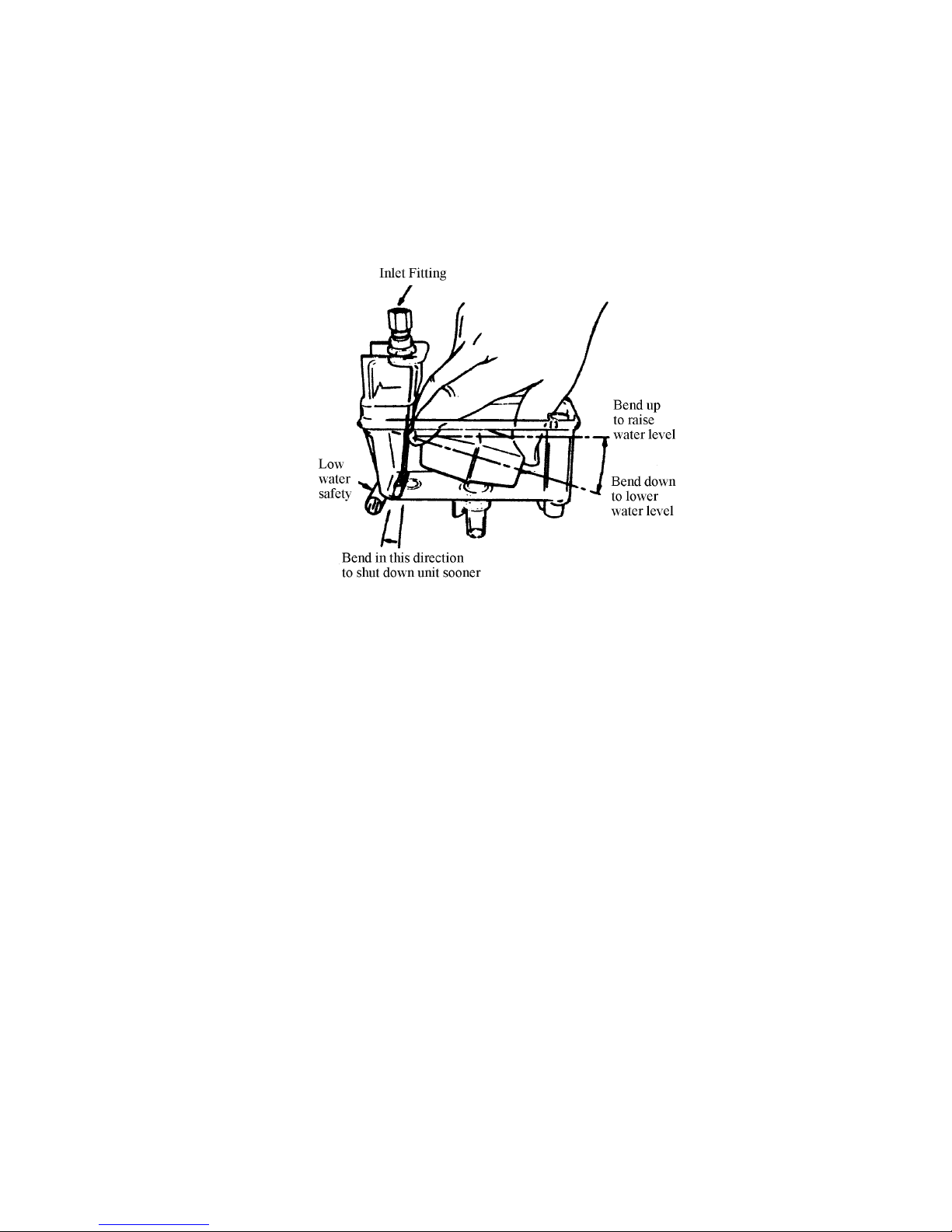
NOTE: If the Unit will not start, be sure the water reservoir is full. The low water safety control must be
properly adjusted to start and shut down the Unit. If the water level drops below the bottom of the reservoir, the Unit must shut down. Adjustment is made by moving the magnet up or down.
FIGURE 1. FLOAT ADJUSTMENT
Water Level Control Adjustment – If necessary, adjust the float by bending the float arm up or down as need-
ed. Push the float assembly down until the Unit stops running. Release the float and the Unit will restart. Keep
water in the reservoir at the level line while the Unit is in operation (See Figure 1).
Low Water Safety Control – Adjust the magnet by bending the magnet arm as shown in Figure 1 to shut down
the Unit if the water level drops below the line on the side of the reservoir.
Bin Control – Remove four clips from top of the bin cover and lift cover so the bin control switch can be manu-
ally lifted until the Unit shuts down. Release the plate and unit will restart
Dispense Switch and Mechanism – By depressing the dispense switch, the dispense mechanism door on the
storage bin will open, and the agitator will rotate counterclockwise.
NOTE: If any of these checks or adjustments cannot be achieved, refer to Troubleshooting Section of
this manual or call our Technical Support Center for assistance.
5 630460082

GUIDE TO SERVICE
IMPORTANT: Prventive maintenance can increase the trouble-free life of your Ice Maker. Failure to
perform preventive maintenance could void your equipment warranty.
ICE MAKER CLEANING AND SANITIZING PROCEDURES
IMPORTANT: Do not use any of the ice made during cleaning operations.
Clean and sanitize ice storage area when cleaning Ice Maker.
1. Turn Ice Maker off.
2. Shut off water supply.
3. Remove ice from storage bin.
4. Mix approved cleaner (2 gallons as directed). Recommended cleaner: Calgon Corp. or Virginia Chemicals,
ice machine cleaner. Mixture: 3–1/3 ounces per gallon water. Do not use nickel safe cleaners.
5. Turn Ice Maker on and add cleaner solution to water level control (float reservoir) until 2 gallons have been
used.
6. Turn on water supply and operate Ice Maker for 15 minutes.
7. Turn Ice Maker off. Remove and discard all ice.
8. Sanitize using household liquid bleach (50 ppm chlorine). Mixture: 1 fluid ounce per gallon room temperature water. Allow a two minute exposure time.
9. Sanitize pre–cleaned inside areas of storage bin liner, door frame, door, as well as all exposed surfaces of
the evaporator assembly and the bin shutoff assembly with sanitizing solution. Allow to air dry.
MAINTENANCE
Preventative Maintenance can increase the trouble-free life of your Ice Maker. Many Authorized IMI Service
Agencies offer service contracts. Contact your local distributor for further information.
MONTHLY
1. Clean the condenser coil. Use a brush, vacuum cleaner, or blow from inside the coil with air or CO2 gas.
2. Inspect the water feed reservoir at least once a month until a definite pattern for cleaning and sanitizing
has been established.
QUARTERLY
This is the maximum period of time between cleaning and sanitizing the Ice Maker. In addition to recommended
monthly procedure, and if a more frequent cleaning and sanitizing pattern has not been established, the Ice
Maker must be cleaned and sanitized quarterly.
SEMI-ANNUALLY
Semi-annually, in addition to all previously established service procedures, perform the following:
1. Check for water leaks; tube connections, water fittings, and the lower icemaker water seal.
6630460082
2. Check the drain tubes for clogs and ”aged” tubes. Replace if tubes are stained or brittle.
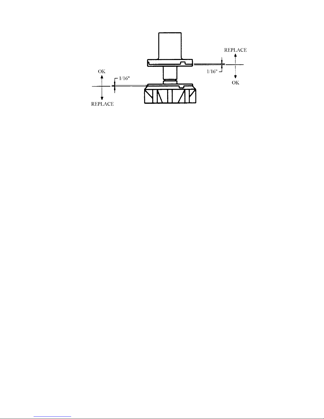
FIGURE 2. AUGER ASSEMBLY
3. Check for signs of condensation. Clean where necessary and replace insulation properly.
4. Check safety circuits for proper operation.
5. Check refrigeration system (see REFRIGERATION SYSTEMS section of this manual).
6. Check Unit for abnormal noise. Tighten machine and cabinet screws, if necessary.
7. Check white upper bearings on auger assembly (see Figure 2). If bearing are less than 1/16-inch thick,
replace the bearings.
W ATER LEVEL CONTROL
WATER LEVEL CONTROL OPERATION
When water is introduced through the inlet fitting, the float rises (see Figure 1). The float pushes against a lever
that in turn, forces the poppet assembly against the inlet fitting valve seat that seals the water off. Before the
water inlet is sealed, the safety switch is operated. In the event of a water failure, the float would drop down and
operate the safety switch to shut off the Unit.
If water level control will not shut off and seal at level as indicated, be sure inlet pressure does not exceed recommended factory operating range.
Under ordinary circumstances, the water level control adjustment should not be necessary providing the control
was properly adjusted when the Unit was installed or relocated (see “Water Level Control Adjustment ” in
“INSTALLATION INSTRUCTIONS” SECTION of this manual). If however, the water level control becomes inop-
erative, repair or replace the control.
PURPOSE OF WATER LEVEL CONTROL
1. To automatically maintain the proper water level in the evaporator when the Unit is operating and making
ice.
2. A safety switch is operated in the event of an interruption in the water supply.The switch shuts off the electrical power to the Ice Maker and it’s refrigeration system. The switch will reset as soon as the cause of
the water failure has been corrected and the proper water level in the Ice Maker has again been reached.
3. The transparent bowl not only provides a visible check of the water level, but also is a good guide to the
internal conditions which exist within the Ice Maker assembly itself (see cleaning procedure).
7 630460082
 Loading...