

Page 1
INSTALLATION MANUAL
Quest Bib Option Kit
Release Date: November 28, 2012
Publication Number: 720901123INS
Revision Date: March 24, 2014
Revision: E
Visit the Cornelius web site at
www.cornelius.com for all your Literature needs.
Page 2

The products, technical information, and instructions contained in this manual are subject to change without notice.
These instructions are not intended to cover all details or variations of the equipment, nor to provide for every possi
ble contingency in the installation, operation or maintenance of this equipment. This manual assumes that the person(s) working on the equipment have been trained and are skilled in working with electrical, plumbing, pneumatic,
and mechanical equipment. It is assumed that appropriate safety precautions are taken and that all local safety and
construction requirements are being met, in addition to the information contained in this manual.
This Product is warranted only as provided in Cornelius’ Commercial Warrant applicable to this Product and is subject to all of the restrictions and limitations contained in the Commercial Warranty.
Cornelius will not be responsible for any repair, replacement or other service required by or loss or damage resulting
from any of the following occurrences, including but not limited to, (1) other than normal and proper use and normal
service conditions with respect to the Product, (2) improper voltage, (3) inadequate wiring, (4) abuse, (5) accident,
(6) alteration, (7) misuse, (8) neglect, (9) unauthorized repair or the failure to utilize suitably qualified and trained per
sons to perform service and/or repair of the Product, (10) improper cleaning, (11) failure to follow installation, operating, cleaning or maintenance instructions, (12) use of “non-authorized” parts (i.e., parts that are not 100%
compatible with the Product) which use voids the entire warranty, (13) Product parts in contact with water or the
product dispensed which are adversely impacted by changes in liquid scale or chemical composition.
Contact Information:
To inquire about current revisions of this and other documentation or for assistance with any Cornelius product contact:
www.cornelius-usa.com
800-238-3600
-
-
Trademarks and Copyrights:
This document contains proprietary information and it may not be reproduced in any way without permission from
Cornelius.
This document contains the original instructions for the unit described.
CORNELIUS INC
101 Regency Drive
Glendale Heights, IL
Tel: + 1 800-238-3600
Printed in U.S.A.
Page 3

Quest BIB Option Installation Guide
!
WARNING:
!
WARNING:
!
WARNING:
CAUTION:
!
SAFETY INSTRUCTIONS
SAFETY
Before starting installation, read and understand all safety label and warnings on the machine. Also review and
understand all safety instructions in the owners, installation and service manuals.
Failure to comply could result in serious injury, death or damage to the equipment.
QUALIFIED SERVICE PERSONNEL
Only trained and certified electrical, plumbing and refrigeration technicians should service this unit.
All wiring and plumbing must conform to national and local codes. Failure to comply could
result in serious injury, death or equipment damage.
SAFETY PRECAUTIONS
This unit has been specifically designed to provide protection against personal injury. To ensure continued
protection observe the following:
Disconnect power to the unit before servicing. Follow all lock out/tag out procedures established by the user. Verify all
power is off to the unit before performing any work.
Failure to comply could result in serious injury, death or damage to the equipment.
Always be sure to keep area around the unit clean and free of clutter.
Failure to keep this area clean may result in injury or equipment damage.
© 2003-2014, Cornelius Inc. - 1 - Publication Number: 720901123INS
Page 4
Quest BIB Option Installation Guide
4holesonthe
rearpanel
INSTALLATION INSTRUCTIONS
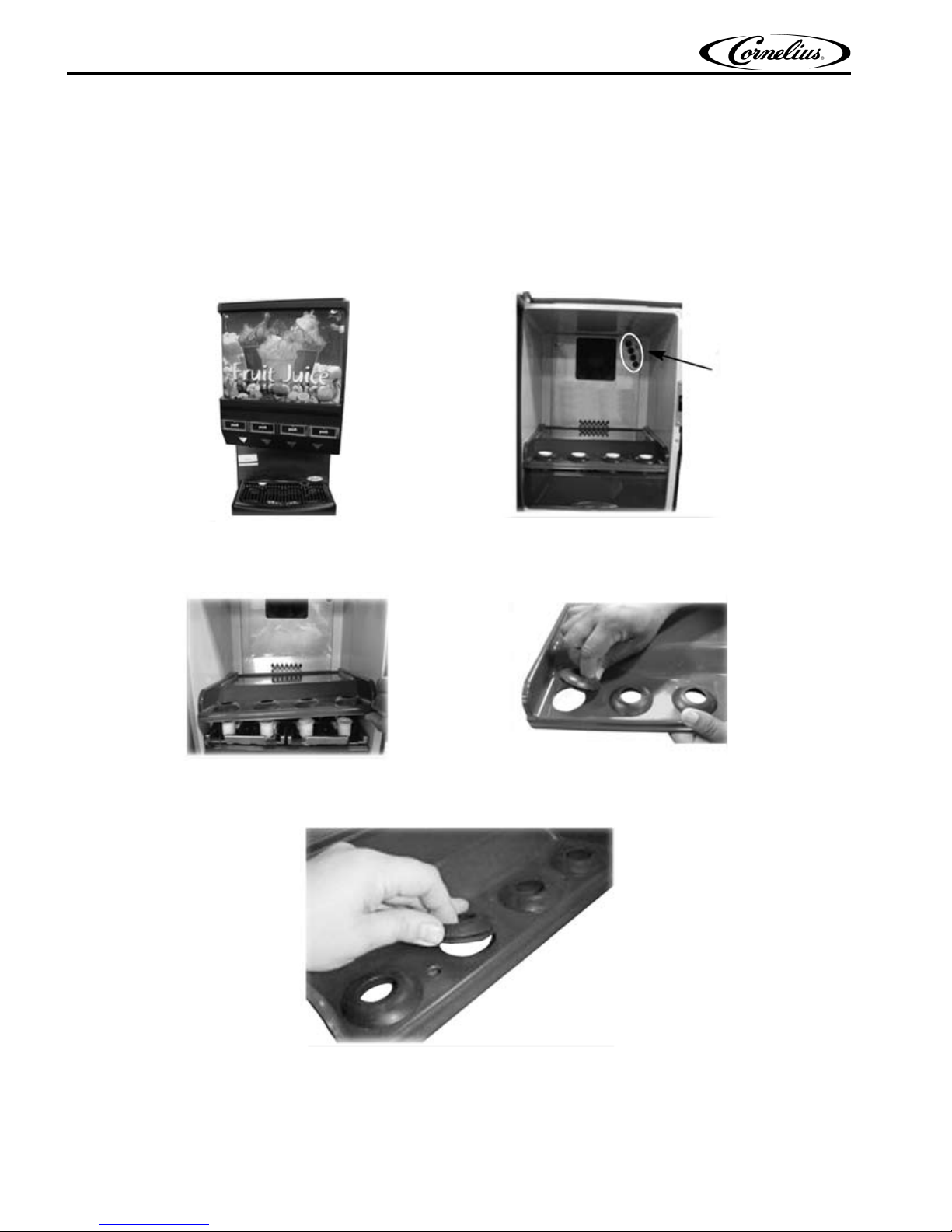
NOTE: P/N 629097210 is used for Quest 4, w/o rear cabinet back panel, P/N 729011125 is used for
Quest 4, 4 hole BIB, P/N 729011126 is used for Quest 2, 2 hole BIB
1. Verify that the back panel of the unit has the 4-hole pattern, as shown in Figure 1.
NOTE: Does not apply to P/N 729011125 & 729011126 kits.
If the back panel cabinet has been updated with the 4-hole pattern proceed to Step 9, if not continue to
Step 2.
Figure 1.
2. Remove the shelf from the top of the platform assemblies and slowly lift it out of the cabinet, as shown in
Figure 2. When the shelf is removed from the unit, remove the four rubber grommets from the shelf.
Figure 2.
3. Install the rubber grommets removed in Step 2 into the new shelf, as shown in Figure 3.
Publication Number: 720901123INS - 2 - © 2003-2014, Cornelius Inc.
Figure 3.
Page 5
Quest BIB Option Installation Guide
(a)
(b)
(c) (d)
(a)
(b)
(c)
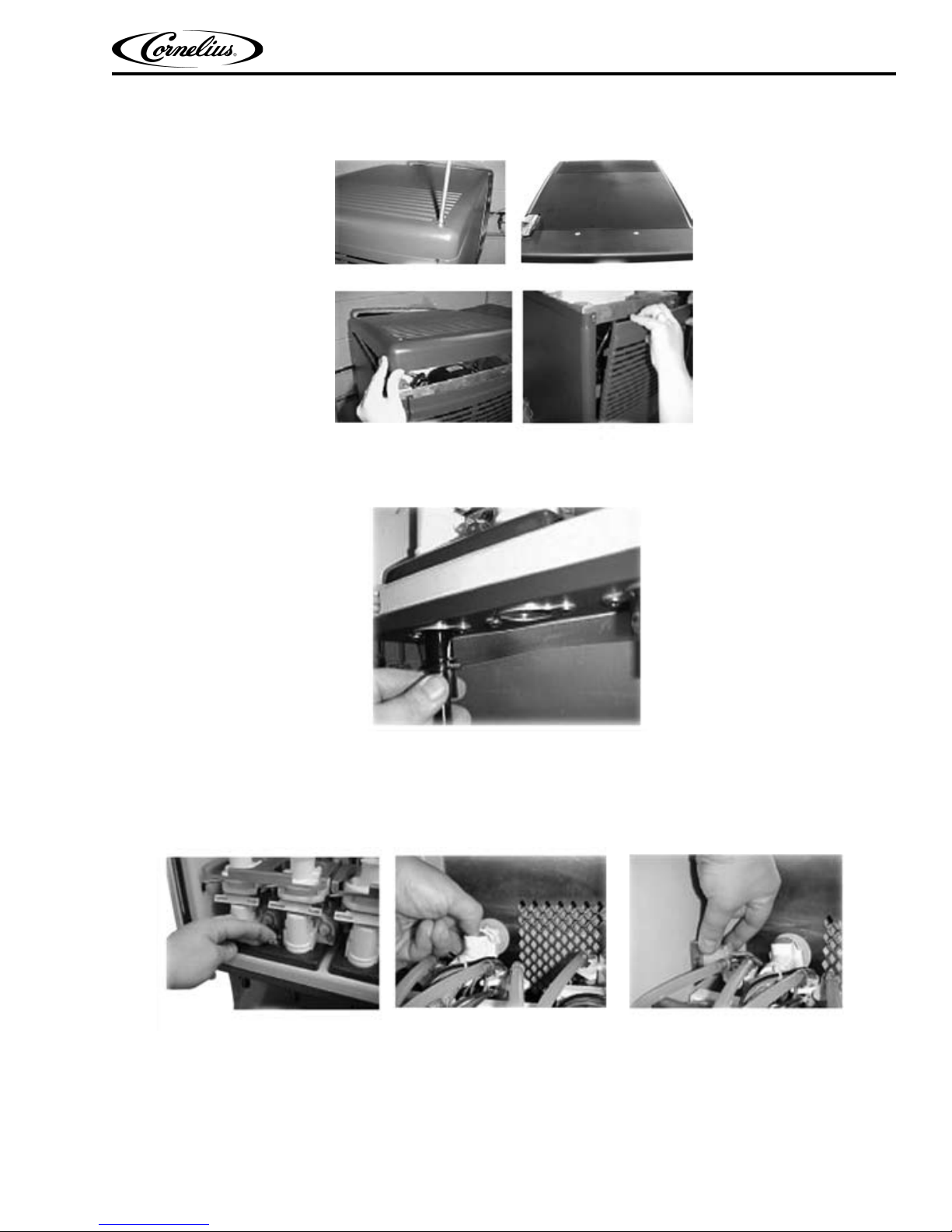
4. Unscrew the top panel (a). Remove the top panel (b). Slide the panel out until it clears the door hinge (c).
Remove the back panel pulling up and out (d).
Figure 4.
5. Remove the nozzles and static mixers from the unit.
6. Unlatch the platform assemblies and lift them over the latch (a). Disconnect the water lines (b) disconnect
the electrical connections (c) remove the platform assemblies.
© 2003-2014, Cornelius Inc. - 3 - Publication Number: 720901123INS
Figure 5.
Figure 6.
Page 6

Quest BIB Option Installation Guide
(a)
(b)
(c)
(d)
(a)
(b)
7. Remove the existing back panel from the cabinet (a) and (b). Remove the fan from the panel (c) and (d).
IMPORTANT: Be careful NOT to pull on the fan wires.
NOTE: (c) shows the back panel with 10-32 screws.
(d) shows the back panel with integrated plastic screw inserts.
Figure 7.
8. Pry open the fan shroud using a screwdriver, as shown in (a). Attach the fan to the new back panel
included in the kit. Be careful NOT to pull on the fan wires. Install the new back panel on the cabinet as
shown on the right.
9. Replace the fan shroud with the screw inserts provided with the replacement shroud.
IMPORTANT: DO NOT pinch the fan wires between the fan and the cabinet or between the panel
and the evaporator. Minimize the risk of pinching the wires by gently pulling them from the rear of
the unit, removing any slack.
Figure 8.
Publication Number: 720901123INS - 4 - © 2003-2014, Cornelius Inc.
Page 7

Quest BIB Option Installation Guide
(a)
(b)
10. Remove the front catch strike plate bracket (a). Remove the two additional screws on the back of the unit to
allow for removal of the side panel (b). Remove the side panel by pulling it out (b).
IMPORTANT: If your kit contains the black plastic panel (P/N 620056690) with the slot, skip to Step
11.
Figure 9.
IMPORTANT: This step requires the use of a drill and a small saw blade.
11. Use the appropriate template shown on the right to cut out a slot for the tube clearance in the back cabinet
panel. Drill an initial clearance hole, then use the saw blade to cut the appropriate size slot. Cut a 0.625” by
1.75” wide slot for the two-flavor unit. Cut a 0.625” high by 3.5” wide slot for the four-flavor unit. Remove
any sharp edges.
Figure 10.
© 2003-2014, Cornelius Inc. - 5 - Publication Number: 720901123INS
Page 8

Quest BIB Option Installation Guide
(a)
(b)
Thermal
Shield
Tub ingRouting
Region
12. Remove the four black plugs on the back panel and replace them with the white grommets provided in the
kit.
Figure 11.
13. Slip the Oetiker clamp over the tubing (a). Use the Oetiker pliers (b), to crimp the ears of the clamp to seal
the tubing.
14. The top view of the machine as shown on the right and dress the tubing routing as shown in the Figure 13.
This will keep the tubing away from the heat of the discharge line and compressor being blocked by the
thermal shield.
NOTE: Applies for LM1 units only.
Publication Number: 720901123INS - 6 - © 2003-2014, Cornelius Inc.
Figure 12.
Figure 13.
Page 9

Quest BIB Option Installation Guide
(a)
(b)
15. From the inside of the unit, feed the tubing through the holes in the back of the cabinet (a).
A. Save the foam plugs as they will be re-used if the BIB option kit is ever uninstalled (b).
B. Ensure that the tubes will not contact the compressor.
C. Adjust the length of the tubing to allow access to the furthest drink port (a).
D. Mark the tubing at the back of the unit with the matching drink selection.
Figure 14.
16. Pull the tubing through the side of the unit, away from the thermal shield as shown in the Figure 15.
Figure 15.
17. From the inside of the unit, continue feeding the remaining tubing through the holes in the back of the
cabinet. Align the tubing vertically in the space between the shield and the side frame.
© 2003-2014, Cornelius Inc. - 7 - Publication Number: 720901123INS
Figure 16.
Page 10

Quest BIB Option Installation Guide
18. Using the zip tie, to secure the tubing set away from the thermal shield as shown in the Figure 17. DO NOT
cause the tubing to kink with the zip tie.
Figure 17.
19. Pull the tubing through the slot in the back panel. Ensure that the tubing does not kink.Replace the back
panel of the unit by aligning the four locating hooks with the slot on the frame.
Figure 18.
20. Replace the back and side panels that were removed in Step 6.
Figure 19.
21. Re-install the platform assemblies, reconnect the water and electrical connections and install the new
shelf.
Publication Number: 720901123INS - 8 - © 2003-2014, Cornelius Inc.
Figure 20.
Page 11

Quest BIB Option Installation Guide
22. Insert the bottle adapter end of the tubing into the appropriate station.
Figure 21.
23. Install the hold brackets as shown in Figure 22. for the four flavor kit, the wider bracket goes on the right
side of the unit.
Figure 22.
24. The completed assembly should look like as shown in Figure 23.
Figure 23.
© 2003-2014, Cornelius Inc. - 9 - Publication Number: 720901123INS
Page 12

Quest BIB Option Installation Guide
Publication Number: 720901123INS - 10 - © 2003-2014, Cornelius Inc.
Page 13

Page 14

Cornelius Inc.
www.cornelius.com
 Loading...