

Page 1

Operator’s Manual
THE PROFILE™ ICE/DRINK DISPENSER
Model: PR150 BC
Release Date: October 5, 2001
Publication Number: 620918702
Revision Date: March 27, 2014
Revision: G
Visit the Cornelius web site at
www.cornelius.com for all your Literature needs.
Page 2

The products, technical information, and instructions contained in this manual are subject to change without notice.
These instructions are not intended to cover all details or variations of the equipment, nor to provide for every possi
ble contingency in the installation, operation or maintenance of this equipment. This manual assumes that the person(s) working on the equipment have been trained and are skilled in working with electrical, plumbing, pneumatic,
and mechanical equipment. It is assumed that appropriate safety precautions are taken and that all local safety and
construction requirements are being met, in addition to the information contained in this manual.
This Product is warranted only as provided in Cornelius’ Commercial Warrant applicable to this Product and is subject to all of the restrictions and limitations contained in the Commercial Warranty.
Cornelius will not be responsible for any repair, replacement or other service required by or loss or damage resulting
from any of the following occurrences, including but not limited to, (1) other than normal and proper use and normal
service conditions with respect to the Product, (2) improper voltage, (3) inadequate wiring, (4) abuse, (5) accident,
(6) alteration, (7) misuse, (8) neglect, (9) unauthorized repair or the failure to utilize suitably qualified and trained per
sons to perform service and/or repair of the Product, (10) improper cleaning, (11) failure to follow installation, operating, cleaning or maintenance instructions, (12) use of “non-authorized” parts (i.e., parts that are not 100%
compatible with the Product) which use voids the entire warranty, (13) Product parts in contact with water or the
product dispensed which are adversely impacted by changes in liquid scale or chemical composition.
Contact Information:
To inquire about current revisions of this and other documentation or for assistance with any Cornelius product contact:
www.cornelius-usa.com
800-238-3600
-
-
Trademarks and Copyrights:
This document contains proprietary information and it may not be reproduced in any way without permission from
Cornelius.
This document contains the original instructions for the unit described.
CORNELIUS INC
101 Regency Drive
Glendale Heights, IL
Tel: + 1 800-238-3600
Printed in U.S.A.
Page 3

TABLE OF CONTENTS
Safety Instructions . . . . . . . . . . . . . . . . . . . . . . . . . . . . . . . . . . . . . . . . . . . . . . . . . . . . . . . . . . . . . 1
Read And Follow All Safety Instructions . . . . . . . . . . . . . . . . . . . . . . . . . . . . . . . . . . . . . . . . . 1
Safety Overview . . . . . . . . . . . . . . . . . . . . . . . . . . . . . . . . . . . . . . . . . . . . . . . . . . . . . . . . 1
Recognition. . . . . . . . . . . . . . . . . . . . . . . . . . . . . . . . . . . . . . . . . . . . . . . . . . . . . . . . . . . . 1
Different Types Of Alerts. . . . . . . . . . . . . . . . . . . . . . . . . . . . . . . . . . . . . . . . . . . . . . . . . . . . . 1
Safety Tips . . . . . . . . . . . . . . . . . . . . . . . . . . . . . . . . . . . . . . . . . . . . . . . . . . . . . . . . . . . . . . . 1
Qualified Service Personnel . . . . . . . . . . . . . . . . . . . . . . . . . . . . . . . . . . . . . . . . . . . . . . . . . . 1
Safety Precautions . . . . . . . . . . . . . . . . . . . . . . . . . . . . . . . . . . . . . . . . . . . . . . . . . . . . . . . . . 2
Shipping And Storage . . . . . . . . . . . . . . . . . . . . . . . . . . . . . . . . . . . . . . . . . . . . . . . . . . . . . . . 2
Co2 (Carbon Dioxide) Warning . . . . . . . . . . . . . . . . . . . . . . . . . . . . . . . . . . . . . . . . . . . . . . . . 2
Mounting In Or On A Counter . . . . . . . . . . . . . . . . . . . . . . . . . . . . . . . . . . . . . . . . . . . . . . . . . 2
Description. . . . . . . . . . . . . . . . . . . . . . . . . . . . . . . . . . . . . . . . . . . . . . . . . . . . . . . . . . . . . . . . . . . 3
Specifications . . . . . . . . . . . . . . . . . . . . . . . . . . . . . . . . . . . . . . . . . . . . . . . . . . . . . . . . . . . . . 3
Installation Instructions . . . . . . . . . . . . . . . . . . . . . . . . . . . . . . . . . . . . . . . . . . . . . . . . . . . . . . . . . 4
Countertop Installation . . . . . . . . . . . . . . . . . . . . . . . . . . . . . . . . . . . . . . . . . . . . . . . . . . . . . . 4
Cleaning And Maintenance Instructions . . . . . . . . . . . . . . . . . . . . . . . . . . . . . . . . . . . . . . . . . . . 7
Daily Cleaning: . . . . . . . . . . . . . . . . . . . . . . . . . . . . . . . . . . . . . . . . . . . . . . . . . . . . . . . . . 7
Daily Maintenance: . . . . . . . . . . . . . . . . . . . . . . . . . . . . . . . . . . . . . . . . . . . . . . . . . . . . . . 7
Weekly Cleaning: (In Addition To Daily Procedures) . . . . . . . . . . . . . . . . . . . . . . . . . . . . 7
Monthly Cleaning: (In Addition To Daily And Weekly Procedures). . . . . . . . . . . . . . . . . . 8
Yearly Maintenance: . . . . . . . . . . . . . . . . . . . . . . . . . . . . . . . . . . . . . . . . . . . . . . . . . . . . . 8
Unit Requiring Remote Carbonator . . . . . . . . . . . . . . . . . . . . . . . . . . . . . . . . . . . . . . . . . 9
Adjusting Syrup Source Co2 Regulator.. . . . . . . . . . . . . . . . . . . . . . . . . . . . . . . . . . . . . . 9
Adjusting Dispensing Valves Water Flow Rate . . . . . . . . . . . . . . . . . . . . . . . . . . . . . . . . . . . . 9
Adjusting Water-to-syrup “ratio” (Brix) Of Dispensed Product . . . . . . . . . . . . . . . . . . . . . . . 10
Start-up And Operating Instructions . . . . . . . . . . . . . . . . . . . . . . . . . . . . . . . . . . . . . . . . . . . . . . 12
Auger Assembly Breakdown . . . . . . . . . . . . . . . . . . . . . . . . . . . . . . . . . . . . . . . . . . . . . . . . . 12
Cleaning And Sanitizing Instructions . . . . . . . . . . . . . . . . . . . . . . . . . . . . . . . . . . . . . . . . . . . . . . 14
Cleaning Dispenser . . . . . . . . . . . . . . . . . . . . . . . . . . . . . . . . . . . . . . . . . . . . . . . . . . . . 14
1. Cleaning Exterior Surfaces . . . . . . . . . . . . . . . . . . . . . . . . . . . . . . . . . . . . . . . . . . . . . 14
2. Cleaning Interior Surfaces . . . . . . . . . . . . . . . . . . . . . . . . . . . . . . . . . . . . . . . . . . . . . 14
Cleaning Dispensing Valves . . . . . . . . . . . . . . . . . . . . . . . . . . . . . . . . . . . . . . . . . . . . . . . . . 16
Sanitizing Syrup Tanks System . . . . . . . . . . . . . . . . . . . . . . . . . . . . . . . . . . . . . . . . . . . . 16
Sanitize B–I–B Systems . . . . . . . . . . . . . . . . . . . . . . . . . . . . . . . . . . . . . . . . . . . . . . . . . 16
Ice Auger Speed Control. . . . . . . . . . . . . . . . . . . . . . . . . . . . . . . . . . . . . . . . . . . . . . . . . . . . 17
Troubleshooting. . . . . . . . . . . . . . . . . . . . . . . . . . . . . . . . . . . . . . . . . . . . . . . . . . . . . . . . . . . . . . 20
Blown Fuse Or Circuit Breaker . . . . . . . . . . . . . . . . . . . . . . . . . . . . . . . . . . . . . . . . . . . . . . . 20
Agitator Does Not Turn, Auger Does Not Turn. . . . . . . . . . . . . . . . . . . . . . . . . . . . . . . . . . . 20
Ice Dispenses Continuously. . . . . . . . . . . . . . . . . . . . . . . . . . . . . . . . . . . . . . . . . . . . . . . . . . 20
Slushy Ice. Water In Hopper. . . . . . . . . . . . . . . . . . . . . . . . . . . . . . . . . . . . . . . . . . . . . . . . . 20
Agitator Turns, Auger Does Not Turn.. . . . . . . . . . . . . . . . . . . . . . . . . . . . . . . . . . . . . . . . . . 20
Agitator Turns, Auger Does Not Turn (Cont’d) . . . . . . . . . . . . . . . . . . . . . . . . . . . . . . . . . . . 20
Auger Turns, Agitator Does Not. . . . . . . . . . . . . . . . . . . . . . . . . . . . . . . . . . . . . . . . . . . . . . . 21
Beverages Donot Dispense . . . . . . . . . . . . . . . . . . . . . . . . . . . . . . . . . . . . . . . . . . . . . . . . . 21
Beverages Too Sweet. . . . . . . . . . . . . . . . . . . . . . . . . . . . . . . . . . . . . . . . . . . . . . . . . . . . . . 21
Beverages Not Sweet Enough . . . . . . . . . . . . . . . . . . . . . . . . . . . . . . . . . . . . . . . . . . . . . . . 21
Beverages Not Cold. . . . . . . . . . . . . . . . . . . . . . . . . . . . . . . . . . . . . . . . . . . . . . . . . . . . . . . . 21
Illustrated Parts List . . . . . . . . . . . . . . . . . . . . . . . . . . . . . . . . . . . . . . . . . . . . . . . . . . . . . . . . . . . 22
PR 150 BC Assembly . . . . . . . . . . . . . . . . . . . . . . . . . . . . . . . . . . . . . . . . . . . . . . . . . . . . . . 25
Page 4

Page 5
PR150 BC Ice Drink Dispenser Operator’s Manual
!
DANGER:
!
WARNING:
CAUTION:
!
!
WARNING:
!
SAFETY INSTRUCTIONS
READ AND FOLLOW ALL SAFETY INSTRUCTIONS
Safety Overview
• Read and follow ALL SAFETY INSTRUCTIONS in this manual and any warning/caution labels on the unit (decals, labels or
laminated cards).
• Read and understand ALL applicable OSHA (Occupational Safety and Health Administration) safety regulations before
operating this unit.
Recognition
Recognize Safety Alerts
This is the safety alert symbol. When you see it in this manual or on the unit,
be alert to the potential of personal injury or damage to the unit.
DIFFERENT TYPES OF ALERTS
Indicates an immediate hazardous situation which if not avoided WILL result in serious injury, death or equipment
damage.
Indicates a potentially hazardous situation which, if not avoided, COULD result in serious injury, death, or equipment
damage.
Indicates a potentially hazardous situation which, if not avoided, MAY result in minor or moderate injury or equipment
damage.
SAFETY TIPS
• Carefully read and follow all safety messages in this manual and safety signs on the unit.
• Keep safety signs in good condition and replace missing or damaged items.
• Learn how to operate the unit and how to use the controls properly.
• Do not let anyone operate the unit without proper training. This appliance is not intended for use by very young children or
infirm persons without supervision. Young children should be supervised to ensure that they do not play with the appliance.
• Keep your unit in proper working condition and do not allow unauthorized modifications to the unit.
QUALIFIED SERVICE PERSONNEL
Only trained and certified electrical, plumbing and refrigeration technicians should service this unit. ALL WIRING AND
PLUMBING MUST CONFORM TO NATIONAL AND LOCAL CODES. FAILURE TO COMPLY COULD RESULT IN
SERIOUS INJURY, DEATH OR EQUIPMENT DAMAGE.
©2001-2014, Cornelius Inc. - 1 - Publication Number: 620918702
Page 6

PR150 BC Ice Drink Dispenser Operator’s Manual
!
WARNING:
CAUTION:
!
CAUTION:
!
!
DANGER:
!
WARNING:
SAFETY PRECAUTIONS
This unit has been specifically designed to provide protection against personal injury. To ensure continued protection
observe the following:
Disconnect power to the unit before servicing following all lock out/tag out procedures established by the user. Verify
all of the power is off to the unit before any work is performed.
Failure to disconnect the power could result in serious injury, death or equipment damage.
Always be sure to keep area around the unit clean and free of clutter. Failure to keep this area clean may result in
injury or equipment damage.
SHIPPING AND STORAGE
Before shipping, storing, or relocating the unit, the unit must be sanitized and all sanitizing solution must be drained
from the system. A freezing ambient environment will cause residual sanitizing solution or water remaining inside the
unit to freeze resulting in damage to internal components.
CO2 (CARBON DIOXIDE) WARNING
CO2 displaces oxygen. Strict attention MUST be observed in the prevention of CO2 gas leaks in the entire CO2 and
soft drink system. If a CO
contaminated area before attempting to repair the leak. Personnel exposed to high concentrations of CO
experience tremors which are followed rapidly by loss of consciousness and DEATH.
2 gas leak is suspected, particularly in a small area, IMMEDIATELY ventilate the
2 gas
MOUNTING IN OR ON A COUNTER
When installing the unit in or on a counter top, the counter must be able to support a weight in excess of 450 lbs. to
insure adequate support for the unit. FAILURE TO COMPLY COULD RESULT IN SERIOUS INJURY, DEATH OR
EQUIPMENT DAMAGE.
NOTE: Many units incorporate the use of additional equipment such as icemakers. When any addition
equipment is used you must check with the equipment manufacturer to determine the additional weight the
counter will need to support to ensure a safe installation.
.
Publication Number: 620918702 - 2 - © 2001-2014, Cornelius Inc.
Page 7
PR150 BC Ice Drink Dispenser Operator’s Manual
DESCRIPTION
The Undercounter ice dispenser solves your ice service needs in a sanitary, space saving, economical way.
Designed to be manually filled with ice this dispenser will dispense cubes (up to 1-1/4” in size), cubelets and hard
chipped or cracked ice.
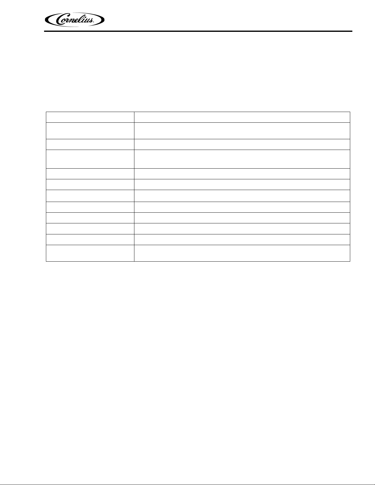
SPECIFICATIONS
Model:
Dimensions
Electrical
Recommended Electrical
Supply
Clearance Required
Drain
CO
or Air Requirements
2
Flavor Selections
Cup Selection
Ice Requirements
Water Supply
Drink Draw Rate
PR150 BC Ice Drink Dispenser (Eight-Flavor)
31-7/8 inches wide X 27-7/8 inches Deep X 21-1/4 inches High with
29 inches Depth Below Countertop
120 VAC/1 Phase/60 Hz/5.2 Amps Total Current Draw
115 VAC/60 Hz/15.0 Amps, 3-Wire Grounded Circuit
54–In. above counter front access.
Base Unit is plumbed for PVC or flex plastic tubing installed to local code.
CO
80-100 PSI supply (preferred) or air = 70 PSI minimum supply.
2 =
Maximum of eight syrup flavors plus plain water and carbonated water.
Five Sizes (12, 16, 21, 32, and 42 0z.)
Ice bin capacity is 150 pounds of ice.
60-PSI flowing pressure (3/4 inch supply with shutoff valve)
Dispenses seven 21 oz. drinks per minute at or below 40° F
continuous.
©2001-2014, Cornelius Inc. - 3 - Publication Number: 620918702
Page 8
PR150 BC Ice Drink Dispenser Operator’s Manual
!
WARNING:
INSTALLATION INSTRUCTIONS
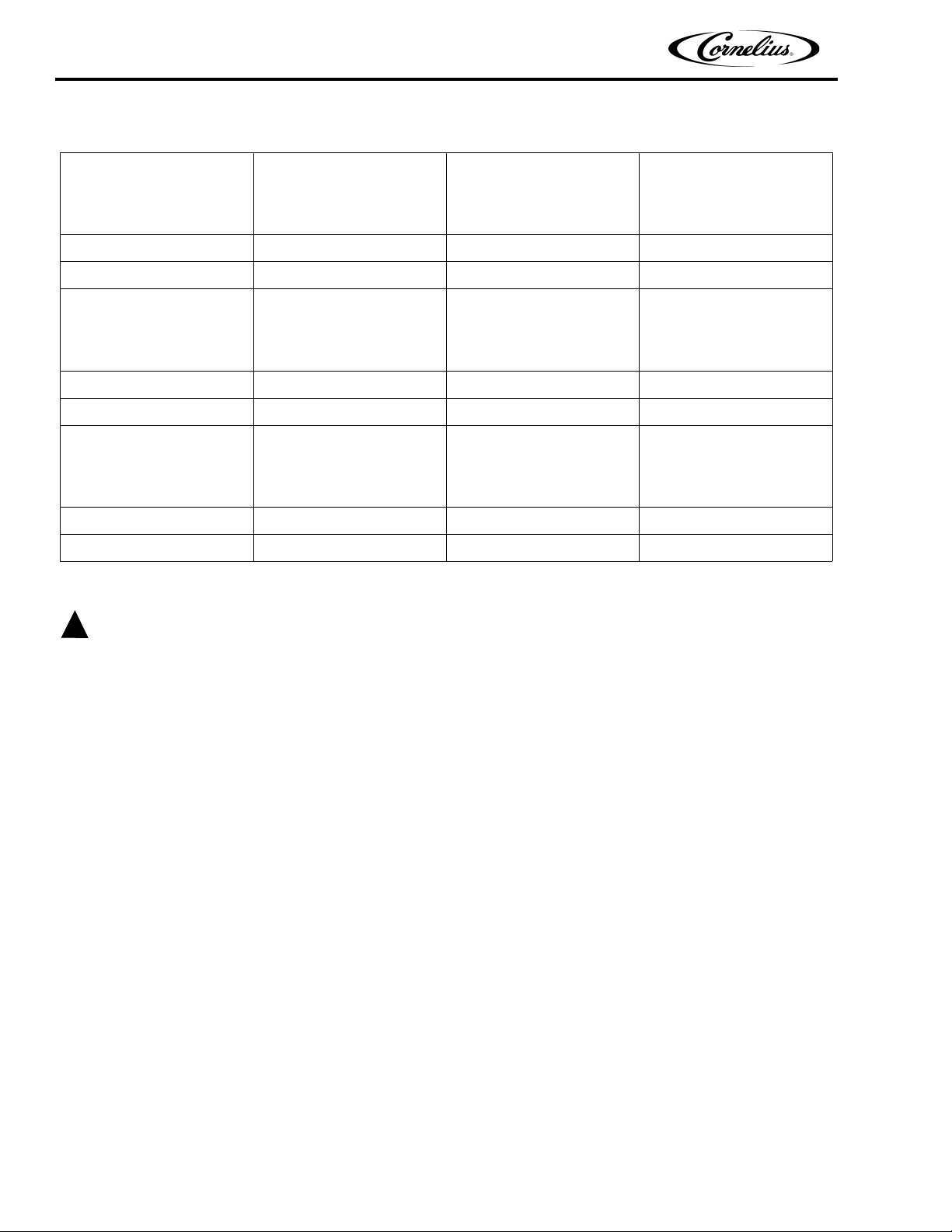
COUNTER HEIGHT
(INCHES)
30 29 1 CONSULT FACTORY
31 29 2 CONSULT FACTORY
32 29 3 620517502
33 29 4 629087406
34 29 5 629087406
34-1/2 29 5-1/2 629087412
35 29 6 629087412
36 29 7 629087412
DISPENSER
(INCHES
COUNTERTOP INSTALLATION
DEPTH
AVAILABLE SPACE
BELOW DISPENSER
(INCHES)
USE KIT NO.
AND
629087406
AND
620517502
It is the responsibility of the installer to ensure that the water supply to the dispensing equipment is provided with
protection against backflow by an air gap as defined in ANSI/ASME A112. 1.2-1976; or an approved vacuum breaker
or other such method as proved effective by test and must comply with all federal, state and local codes.
Failure to comply could result in serious injury, death or damage to the equipment.
Water pipe connections and fixtures directly connected to a potable water supply shall be sized, installed, and
maintained according to federal, state and local laws.
1. Locate the dispenser indoors on a level countertop.
must
The dispenser
opening that
dimension on the countertop using the dimensions given or use the full size template enclosed.
Apply a continuous bead of NSF International (NSF) listed silastic sealant (Dow 732 or equivalent) approximately
1/4 inch inside the dispenser outline dimensions and around all openings. Position the dispenser on the
countertop within the outline dimensions. All excess sealant
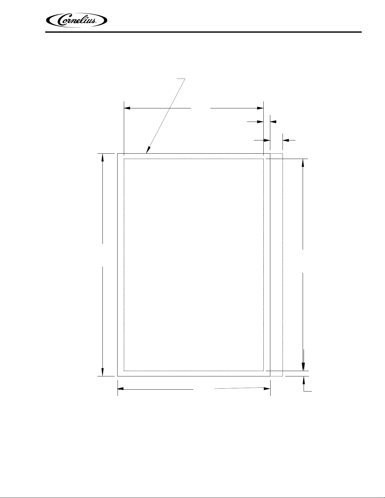
2. The drain tube is routed through the large opening in the bottom of the dispenser. See the MOUNTING TEMPLATE (see Figure 1) for locating the required clearance hole in the countertop for these utility lines. The
power cord is routed through hole in the side of the dispenser electrical control box.
3. SINK DRAIN ASSEMBLY: Connect the drain tube to an open drain. Additional drain tubing is provided with the
Dispenser. The drain tube
result.
A. Use 3/4-inch nominal plastic pipe.
B. To assure proper drainage,
must
bottom of the dispenser.
be sealed to the countertop. The MOUNTING TEMPLATE (see Figure 1) indicates the
be cut in the countertop. Locate the desired position for the dispenser, then mark the outline
must
be wiped away immediately.
must
continuously pitch downward and contain no “traps” or improper drainage will
do not
allow a “trap” to form in the drain line.
Be sure
drain line runs flat with
Publication Number: 620918702 - 4 - © 2001-2014, Cornelius Inc.
Page 9
PR150 BC Ice Drink Dispenser Operator’s Manual
COUNTER CUTOUT
FOR
UNIT DROP IN
FRONT OF COUNTERTOP
FOOT PRINT OF UNIT
ON COUNTERTOP
29 - 5/8
27-3/16
25-3/4
31-7/8
THE ABOVE FIGURE SHOWS THE REQUIRED CUTOUT FOR PLACING THE ICE DISPENSER INTO A COUNTERTOP. THE DASHED
LINE IS THE ACTUAL CUTOUT DIMENSIONS WHILE THE SOLID LINE SHOWS THE AMOUNT OF OVERHANG FOR THE DISPENSER.
4. Clean the hopper interior (See CLEANING INSTRUCTIONS).
5. Connect dispenser power cord to 120 VAC 60 HZ 15-Amp 3-wire grounded receptacle.
©2001-2014, Cornelius Inc. - 5 - Publication Number: 620918702
Figure 1. Mounting Template
Page 10
PR150 BC Ice Drink Dispenser Operator’s Manual
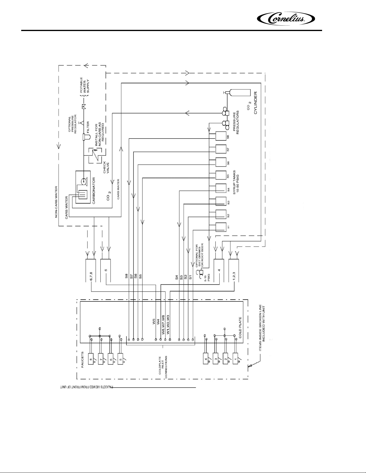
Figure 2. Flow Diagram
Publication Number: 620918702 - 6 - © 2001-2014, Cornelius Inc.
Page 11

PR150 BC Ice Drink Dispenser Operator’s Manual
!
WARNING:
CAUTION:
!
CLEANING AND MAINTENANCE INSTRUCTIONS
These instructions are used on all Cornelius ice drink dispensers. Some models may have additional cleaning
requirements. Those models will have addition procedures listed later in the manual.
Disconnect power to the unit before cleaning or servicing following all lock out / tag out procedures established by
the user. Verify all of the power is off to the unit before performing any work.
Failure to comply could result in serious injury, death or damage to the equipment.
Do not use metal scrapers, sharp objects or abrasives on the ice storage hopper, top cover, agitator disc or exterior
surfaces as damage to the unit may result. Do not use solvents or other cleaning agents as they may attack the
material resulting in damage to the unit.
Soap solution – Use a mixture of mild detergent and warm (100° F ) potable water.
Sanitizing Solution – Dissolve 2 packets (4 oz) of Stera Sheen Green Label into 2 gallons of warm (80 – 100° F)
potable water to ensure 200 ppm of chlorine.
Daily Cleaning:
1. Remove cup rest from drip tray and clean with warm soapy water, rinse with clean water and allow to air
dry.
2. Wipe down the exterior of the unit with warm soapy water, rinse with clean water and allow to air dry.
3. Remove valve nozzles and diffusers and wash in warm soapy water, rinse in clean water and allow to air
dry.
4. Clean the interior of the ice chute using the brush provided with the unit with warm soapy water, rinse with
clean water and allow to air dry.
5. Spray the ice chute inside and out with sanitizer and allow to air dry.
6. Pour warm soapy water down the drains to keep them clean and flowing smoothly.
7. Spray the nozzles and diffusers inside and outside with approved sanitizing solution, reinstall them on the
valves and allow to air dry.
8. Reinstall the cup rest into the drip tray.
9. Pour all remaining sanitizer solution down the drains to help keep the drain clear.
Daily Maintenance:
1. Check the temperature, smell and taste of the product.
2. Check the water pressure coming to the unit using the pressure gauges on the back room package.
3. Check carbonation of the drink
4. Check level of CO2 supply to the system.
5. Check the date on all of the BIB’s (bags in boxes).
Weekly Cleaning: (In addition to daily procedures)
Remove the ice chute cover and clean it along with the back half with warm soapy using the brush provided with
the unit. Rinse with clean water and reinstall on the unit. Spray the ice chute assembly with approved sanitizer
allowing it to air dry.
©2001-2014, Cornelius Inc. - 7 - Publication Number: 620918702
Page 12

PR150 BC Ice Drink Dispenser Operator’s Manual
Monthly Cleaning: (In addition to daily and weekly procedures)
1. Flush and sanitize all syrup lines as well as all of the syrup connectors. (See the sanitize syrup lines
section shown later in this manual).
2. Remove ice from hopper and clean and sanitize the hopper. (See the Cleaning the interior surfaces section
shown later in this manual).
3. While cleaning the hopper use the brush provided with the unit to clean the cold plate surface. To
accomplish this, the brush needs to be extended through the opening in the bottom of the hopper.
Yearly Maintenance:
Have the water pump and check valve inspected and cleaned by a qualified service technician.
Have the CO2 gas check valve inspected and cleaned by a qualified service technician.
Remove the unit’s splash and cold plate cover to clean and sanitize the cold plate surface. (See the cleaning the
cold plate section shown later in this manual).
Publication Number: 620918702 - 8 - © 2001-2014, Cornelius Inc.
Page 13

PR150 BC Ice Drink Dispenser Operator’s Manual
Unit Requiring Remote Carbonator
Adjust CO2 regulator for the remote carbonator to CO
pressure specified in manual provided with the carbonator.
2
Adjusting Syrup Source CO2 Regulator.
SUGAR SYRUP TANKS CO2 REGULATOR
Adjust syrup tanks CO
SYRUP PUMPS (BAG–IN–BOX SYSTEM)
Adjust the syrup pumps CO
regulator to a minimum of 45–psi.
2
regulator to 70–psi.
2
DO NOT EXCEED MAXIMUM CO2 PRESSURE SPECIFIED ON
THE SYRUP PUMPS.
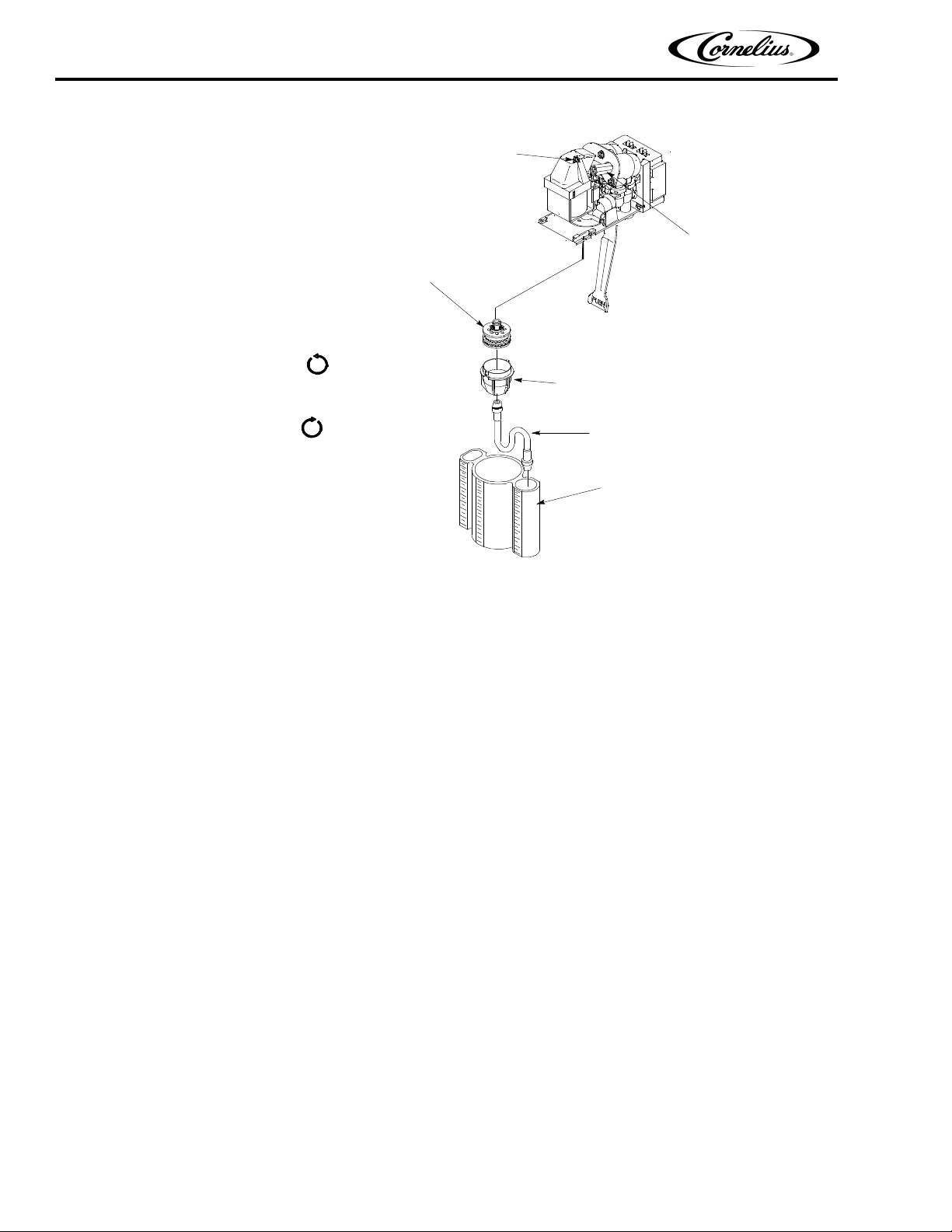
ADJUSTING DISPENSING VALVES WATER FLOW RATE
(see Figure 3)
1. Remove cover from the dispensing valve by lifting the front cover up 1/4 inch and pulling forward.
2. Install syrup diversion tube assembly on the dispensing valve by pushing rubber end of the syrup diversion
tube onto the syrup outlet of the inner nozzle.
3. Measure the water flow rate by dispensing water into a graduated cup for a set period of time.
NOTE: Adjusting screw stops are built into the valve to prevent leakage when the screws are adjusted too
far clockwise. Stop adjusting clockwise when turning resistance increases. Turn the screw counterclockwise 1-1/2 turns after the stop are contacted.
4. Turn the water flow regulator adjusting screw to the left (counterclockwise) to decrease the water flow rate or
turn the adjusting screw to the right (clockwise) to increase the water flow rate, then recheck the flow rate.
Adjustments should be no more than 1/4 turn at a time.
5. Remove syrup diversion tube from the dispensing valve, then install cover on the dispensing valve.
©2001-2014, Cornelius Inc. - 9 - Publication Number: 620918702
Page 14
PR150 BC Ice Drink Dispenser Operator’s Manual
WATER FLOW
REGULATOR
SYRUP FLOW
REGULATOR
INNER NOZZLE
NOZZLE
SYRUP DIVERSION
TUBE
RATIO CUP
Counterclockwise
to Decrease
Clockwise
to Increase
Figure 3. UF–1 Dispensing valve
ADJUSTING WATER-TO-SYRUP “RATIO” (BRIX) OF DISPENSED PRODUCT
(see Figure 3)
NOTE: Make sure the dispensing valve water flow rate is as desired before adjusting the valve for Water–
to–Syrup ‘‘Ratio’’ (Brix) of the dispensed product.
Adjust Water-to-Syrup “Ratio” (Brix) of the dispensed product by using ratio cup (P/N 311100000) and syrup
diversion tube assembly (P/N 319540000) as follows:
1. Remove cover from the dispensing valve by lifting front cover up 1/4 inch and pulling forward.
2. Install syrup diversion tube assembly on the dispensing valve by pushing the rubber end of the syrup diversion
tube onto the syrup outlet of the inner nozzle.
NOTE: Refer to syrup manufacturer’s recommendations on syrup package for water–to–syrup ratio.
3. Dispense enough to fill syrup diversion tube with syrup.
4. Hold large chamber of the ratio cup under the dispensing valve nozzle. Place free end of the syrup diversion
tube into the syrup chamber marked for the proper ratio. Dispense approximately 6 ounces of water into the
ratio cup. Water and syrup levels should be even in cup.
NOTE: Adjusting screw stops are built into the valve to prevent leakage when the screws are adjusted
clockwise too much. Stop adjusting clockwise when turning resistance increases. Turn the screw counterclockwise 1-1/2 turns after the stop are contacted.
Publication Number: 620918702 - 10 - © 2001-2014, Cornelius Inc.
Page 15

PR150 BC Ice Drink Dispenser Operator’s Manual
5. Adjusting Syrup Flow Regulator - If water and syrup levels are uneven in the ratio cup, adjust by
turning the dispensing valve syrup flow regulator adjusting screw labeled SYRUP as follows.
A. For less syrup, turn the adjusting screw counterclockwise no more than 1/4 turn at a time.
B. For more syrup, turn the adjusting screw clockwise no more than 1/4 turn at a time.
6. Repeat water–to–syrup ratio test and adjust syrup flow regulator as many times as necessary until proper
ratio of dispensed drink is achieved.
7. Remove syrup diversion tube assembly from dispensing valve.
8. Install dispensing valve front cover.
©2001-2014, Cornelius Inc. - 11 - Publication Number: 620918702
Page 16

PR150 BC Ice Drink Dispenser Operator’s Manual
START-UP AND OPERATING INSTRUCTIONS
Fill the hopper with ice. Dispense a large cup of ice. Repeat this procedure when ever the dispenser has run out of
ice.
In normal operation, pushing the ice dispenser lever will cause ice to flow from the ice chute. Ice flow will continue
to flow as long as the lever is held depressed.
If the dispenser fails to dispense beverage or ice, refer to TROUBLESHOOTING in back of the manual.
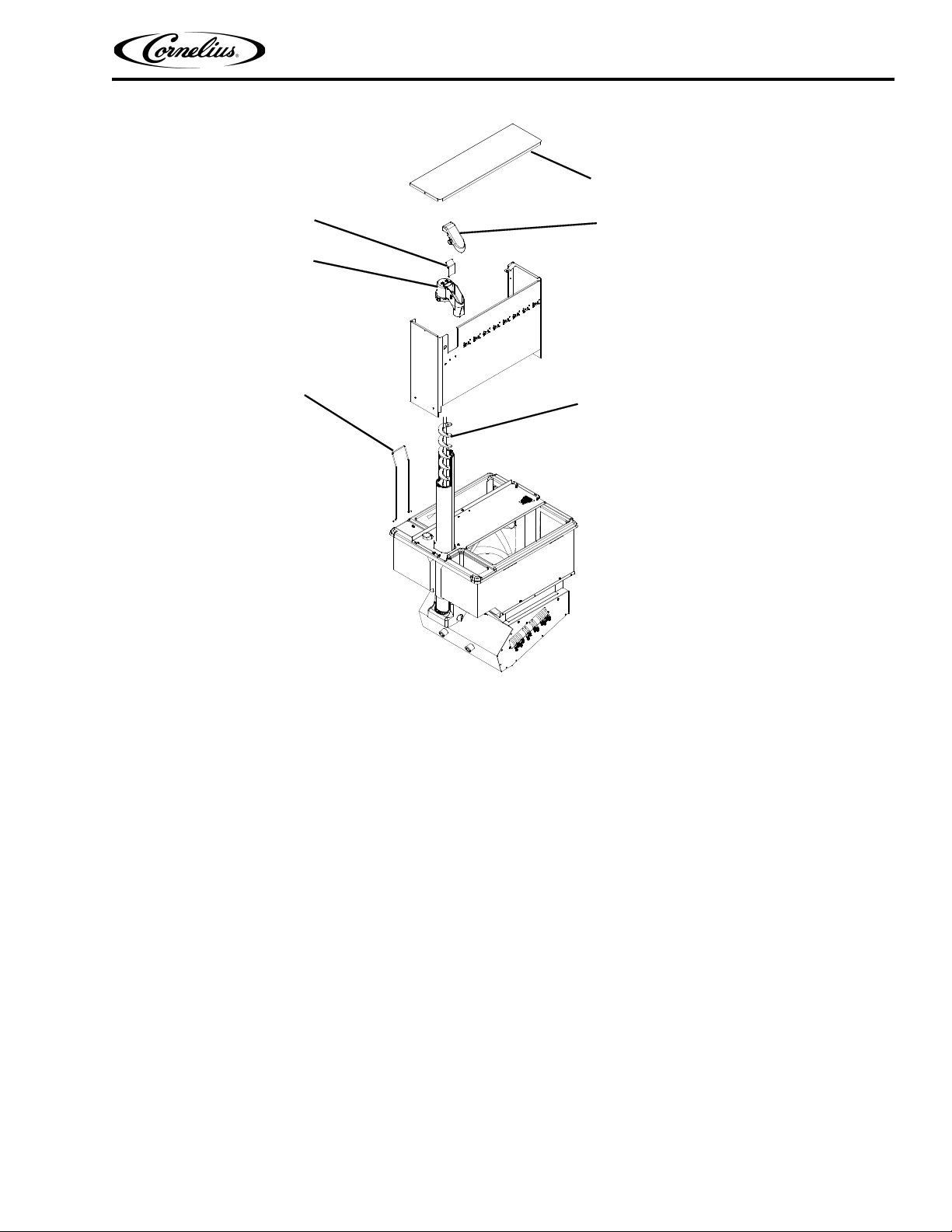
AUGER ASSEMBLY BREAKDOWN
1. For cleaning, the auger assembly is constructed for simple (tools not required) breakdown. First remove the
tower cover (item 69) by removing the 2 knurled screws.
2. Once the tower cap is out of the way you will see a wire retainer (item 77). By placing your fingers on the backside of the ice chute (item 65) with your thumbs pointing upward, place the thumbs on the retainer wire and
with a slight upward movement push the wire retainer towards the rear of the unit. The retainer should pop out
of the saddle and swing backwards.
3. At this point, you should be able to pull up on the ice chute and remove it from the assembly. You will notice that
the ice chute is made up of three pieces. That is the ice chute, the ice chute cover and the auger gate which is
respectively (Items 65, 66, and 67). Take not so that when reassembling the ice chute, the auger gate cradles
in the ice chute with the short tang side up.
4. The auger (Item 73) can now be removed by just grasping it and pulling up. Notice that the bottom of the
auger has a depression in the form of a D pattern. When replacing the auger, it will be necessary to rotate the
auger after insertion in the tube to engage the motor shaft.
Publication Number: 620918702 - 12 - © 2001-2014, Cornelius Inc.
Page 17
PR150 BC Ice Drink Dispenser Operator’s Manual
69
66
67
65
73
77
Figure 4. Auger Assembly
©2001-2014, Cornelius Inc. - 13 - Publication Number: 620918702
Page 18
PR150 BC Ice Drink Dispenser Operator’s Manual
CAUTION:
!
CLEANING AND SANITIZING INSTRUCTIONS
Soap Solution - Use a mixture of mild detergent and warm (100° F) potable water.
Sanitizing Solution
solution to this ratio will create a solution of 200 PPM.
Cleaning Dispenser
1. CLEANING EXTERIOR SURFACES
IMPORTANT: Perform the following daily.
A. Remove cup rest from the drip tray.
B. Wash the drip tray with soap solution. Rinse with potable water and allow solution to run down the drain.
C. Wash cup rest with soap solution and rinse with potable water. Install cup rest in drip tray.
D. Clean all exterior surfaces of the dispenser with soap solution and rinse with potable water.
- Use 1/2-ounce of household bleach in one gallon of potable water. Preparing the sanitizing
2. CLEANING INTERIOR SURFACES
When pouring liquid into the hopper, do not exceed the rate of 1/2-gallan per minute.
IMPORTANT: Perform the following at least once a month.
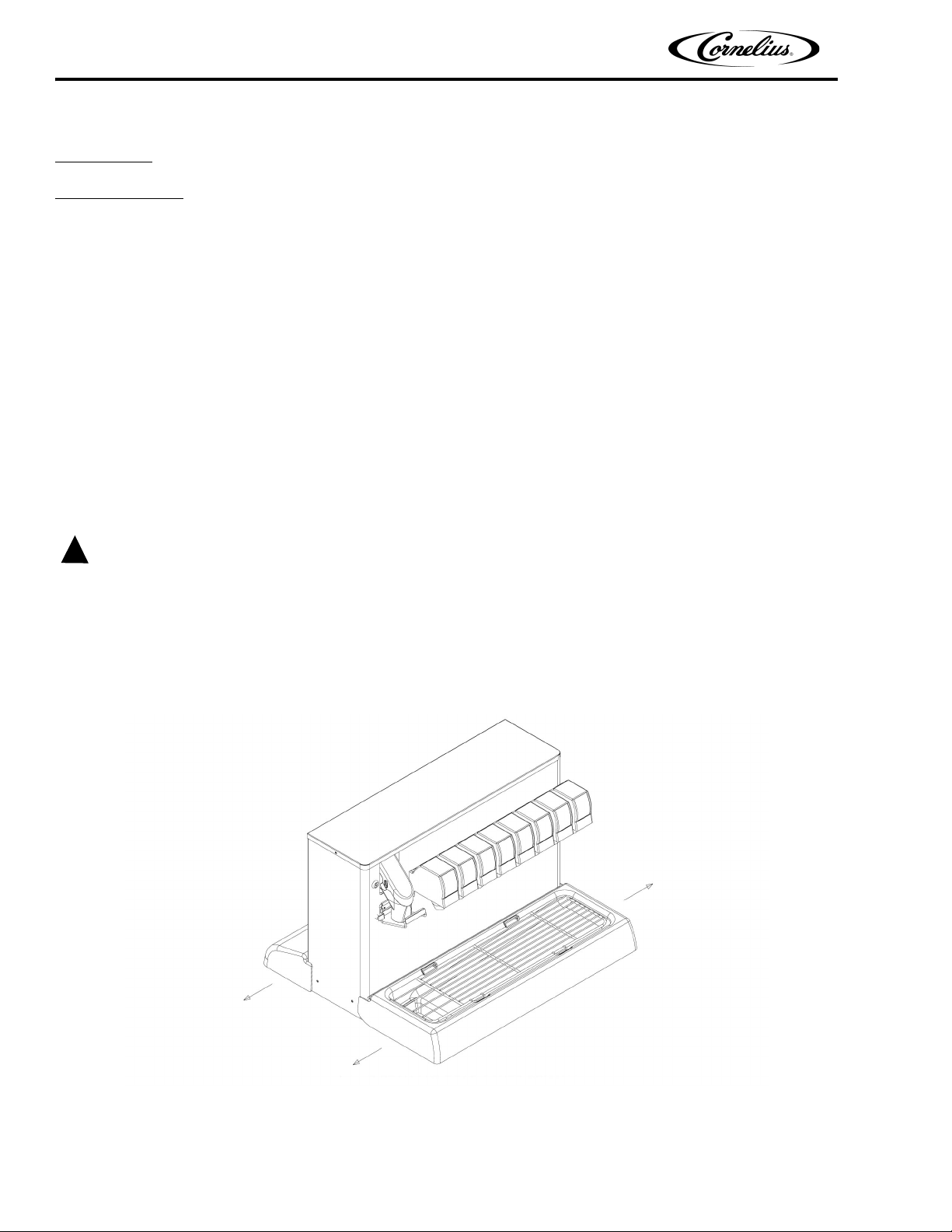
A. Lift drip tray to expose the hopper, then remove all ice from the hopper.
B. The drip tray can be removed from the dispenser by grasping at rear side panels and pulling gently
outward.
Figure 5. Drip Tray and Rear Cover Removal
Publication Number: 620918702 - 14 - © 2001-2014, Cornelius Inc.
Page 19

PR150 BC Ice Drink Dispenser Operator’s Manual
C. Remove agitator disk and agitator assembly.
D. Remove tower cover by removing two thumb screws.
E. Move the retaining bail to the rear of the tower which will allow removal of the ice chute assembly.
F. Grasp the auger by the shaft end and lift out the auger tube. Take care not to damage either end of the
auger.
G. Remove the auger tube by lifting upward. The tube will separate into two halves for easy cleaning when
fully removed.
H. Open the front door of the cabinet below the hopper. This will give you access to the lower auger drive
area and the passage between the hopper and the auger for cleaning.
I. Using the previously prepared detergent solution, clean the valves, the hopper covers, agitator disk,
agitator assembly, interior of the hopper, both halves of the ice chute, auger, auger tubes, and the
lower auger area of the auger housing. Thoroughly rinse all of the previously cleaned parts with potable
water.
J. Reassemble the agitator assembly and disc into the hopper. Make certain the retaining screw is tight.
K. Using a mechanical spray bottle filled with sanitizing solution, spray the entire interior of the hopper and
the agitator assembly. Go to the lower auger drive area and also spray with sanitizing solution. Allow to
air dry.
L. Using the spray bottle, spray the inside of the two halves of the auger tube, the auger, the two halves of
the chute assembly, and the undersides of the right and left covers. Allow to air dry.
M. Reassemble the two halves of the auger tube and place back into it’s mounting. Holding the auger by the
upper shaft end, insert into the guide tube. Make certain that the auger slips into it’s drive pin. The chute
assembly will not assemble properly if the auger is not seated on it’s drive pin. Reassemble the upper
auger and chute assembly onto the auger and lock down by snapping the ball onto the upper housing.
Reinstall the tower cover with the thumb screws.
N. Reinstall the covers. Put the right cover on first before you close the left cover.
3. Last are the auger housings (Items 74 and 75). They are dislodged by pulling upward. Check their orientation
and the fact that the longer tube is on the front side. When positioning the housings back in the dispenser, the
longer tube should be placed first so as to seat in the lower housing to set up the orientation (top and bottom
are marked on end of the tube tab at the top), otherwise the ice chute spout will not point towards the front of
the dispenser.
©2001-2014, Cornelius Inc. - 15 - Publication Number: 620918702
Page 20

PR150 BC Ice Drink Dispenser Operator’s Manual
CLEANING DISPENSING VALVES
Refer to addendum supplied with the unit that is applicable to the manufacturer of the valves installed
on the unit.
Sanitizing Syrup Tanks System
Only trained and qualified persons should perform these cleaning and sanitizing procedures.
Sanitize syrup tanks system as follows:
1. Remove all the quick disconnects from all the tanks. Fill a suitable pail or bucket with soap solution.
2. Submerge all disconnects (gas and liquid) in the soap solution and then clean them using a nylon bristle
brush. (Do not use a wire brush). Rinse with clean water.
3. Prepare sanitizing solution and using a mechanical spray bottle, spray the disconnects.
Allow to air dry.
4. Using a clean, empty tank, prepare five (5) gallons of the sanitizing solution. Rinse the tank disconnects with
approximately 9 oz. of the sanitizing solution. Close the tank.
5. Prepare cleaning tank by filling clean five (5) gallon tank with a mixture of mild detergent and potable water
(120°F).
6. Connect a gas disconnect to the tank and then apply one of the product tubes to the cleaning tank. Operate
the appropriate valve until liquid dispensed is free of any syrup.
7. Disconnect cleaning tank and hook up sanitizing tank to syrup line and CO
8. Energize beverage faucet until chlorine sanitizing solution is dispensed through the faucet. Flush at least two
(2) cups of liquid to ensure that the sanitizing solution has filled the entire length of the syrup tubing.
9. Allow sanitizer to remain in lines for fifteen (15) minutes.
10. Repeat the step above, applying a different product tube each time until all tubes are filled with the sanitizing
solution.
11. For post–mix valves, remove the nozzle and syrup diffuser and clean them in a mild soap solution.
Rinse with clean water and reassemble the nozzle and syrup diffuser on the valve.
12. For pre–mix valves, disconnect all product tubes from the tank of sanitizing solution and then open the valves
to allow the pressure to be relieved. Remove the valves from the dispenser, disassemble and wash
thoroughly in a mild soap solution.
13. Rinse the parts in clean water, reassemble the valve and reconnect it to the dispenser.
system.
2
14. Discard the tank of sanitizing solution and reconnect the product (syrup or pre–mix) tanks. Operate the valves
until all sanitizer has been flushed from the system and only product (syrup or pre–mix) is flowing.
Sanitize B–I–B Systems
1. Remove all the quick disconnects from all the B–I–B containers.
2. Fill a suitable pail or bucket with soap solution.
3. Submerge all disconnects (gas and liquid) in the soap solution and then clean them using a nylon bristle
brush. (Do not use a wire brush). Rinse with clean water.
Publication Number: 620918702 - 16 - © 2001-2014, Cornelius Inc.
Page 21
PR150 BC Ice Drink Dispenser Operator’s Manual
4. Using a plastic pail, prepare approximately five (5) gallons of sanitizing solution.
5. Rinse the B–I–B disconnects in the sanitizing solution.
6. Sanitizing fittings must be attached to each B–I–B disconnect. If these fittings are not available, the fittings
from empty B–I–B bags can be cut from the bags and used. These fittings open the disconnect so the
sanitizing solution can be drawn through the disconnect.
7. Place all the B–I–B disconnects into the pail of sanitizing solution. Operate all the valves until the sanitizing
solution is flowing from the valve. Allow sanitizer to remain in lines for fifteen (15) minutes.
8. Remove the nozzle and syrup diffuser from each valve and clean them in a soap solution. Rinse with clean
water and reassemble the nozzle and syrup diffuser to the valve.
9. Remove the sanitizing fittings from the B–I–B disconnects and connect the disconnects to the appropriate
B–I–B container. Operate the valves until all sanitizer has been flushed from the system and syrup is flowing
freely.
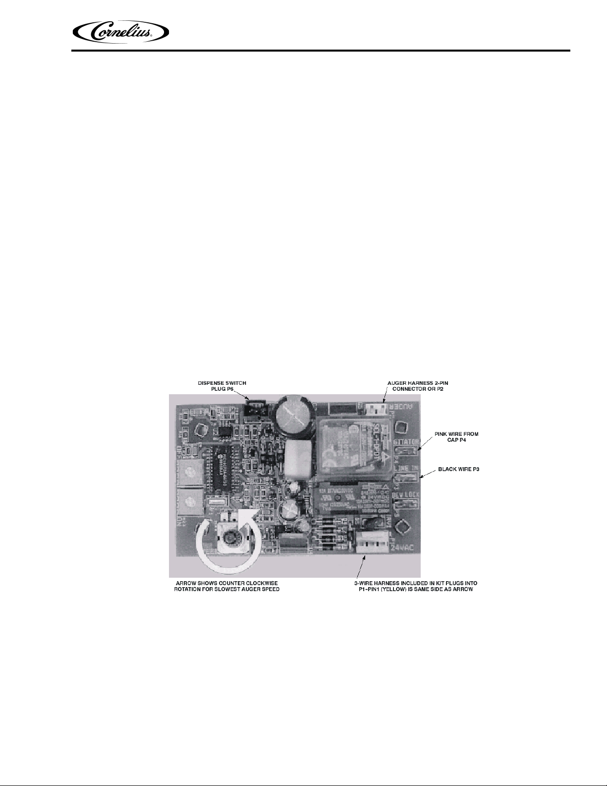
ICE AUGER SPEED CONTROL
The ice auger is a variable speed device. A potentiometer is used to control this speed. The potentiometer is
located on the CB 1 control board (see Figure 4). The CB 1 control board is located inside the electrical control box
which is below the counter facing towards the front of the counter. Removing the three screws and cover will
expose the CB 1 Control board. By turning the potentiometer knob located on the CB1 control board CCW
(counterclockwise) will increase the speed of the ice delivery. Turning the potentiometer knob CW (clockwise) will
decrease the speed of the ice delivery.
Figure 6. Ice Auger Speed Control
©2001-2014, Cornelius Inc. - 17 - Publication Number: 620918702
Page 22
PR150 BC Ice Drink Dispenser Operator’s Manual
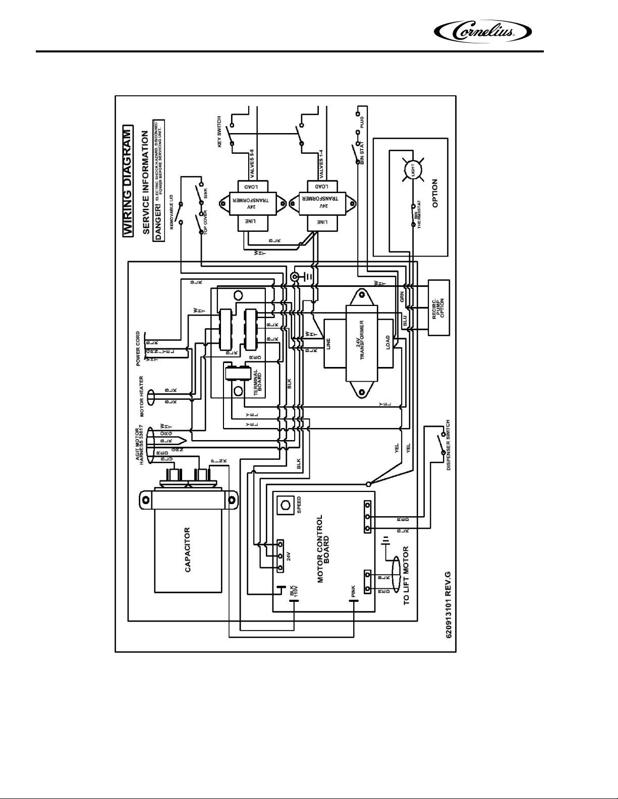
Figure 7. Wiring Diagram
Publication Number: 620918702 - 18 - © 2001-2014, Cornelius Inc.
Page 23
PR150 BC Ice Drink Dispenser Operator’s Manual
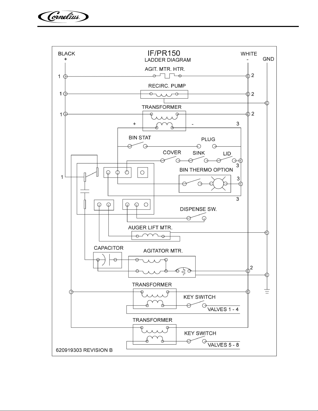
Figure 8. Ladder Diagram
©2001-2014, Cornelius Inc. - 19 - Publication Number: 620918702
Page 24
PR150 BC Ice Drink Dispenser Operator’s Manual
!
WARNING:
TROUBLESHOOTING
If repairs are to be made to a syrup system, disconnect syrup supply from the applicable syrup system, then relieve
the system pressure before proceeding. If repairs are to be made to the CO2 system, stop dispensing, shut off the
CO2 supply, then relieve the system pressure before proceeding. If repairs are to be made to the unit electrical
system, make sure electrical power is disconnected from the unit before proceeding.
IMPORTANT: Only qualified Personnel should service internal components or electrical wiring
Should your unit fail to operate properly, check that there is power to the unit and that the hopper contains ice. If the
unit does not dispense, check the following chart under the appropriate symptoms to aid in locating the defect.
Trouble Probable Cause Remedy
BLOWN FUSE OR CIRCUIT
BREAKER
A. Short circuit in electrical wiring. A. Repair electrical wiring.
AGITATOR DOES NOT TURN,
AUGER DOES NOT TURN.
ICE DISPENSES CONTINUOUSLY.
SLUSHY ICE. WATER IN HOPPER.
B. Inoperative 24 VAC
transformer.
C. Inoperative agitator motor. C. Replace agitator motor.
D. Shorted motor. D. Replace Agitator Auger motor.
A. No electrical power. A. Restore electrical power.
B. Bent depressor plate (does not
actuate switch).
C. Inoperative dispensing switch. C. Replace dispensing switch.
D. Inoperative interlocks, lids not
closed.
E. Inoperative timer board. E. Replace timer board.
F. Inoperative 24 VAC
transformer.
A. Stuck or bent depressor plate
(does not release switch).
B. Inoperative dispensing switch. B. Replace dispensing switch.
C. Improper switch installation. C. Correct switch installation.
D. Inoperative timer board. D. Replace timer board.
A. Blocked drain. A. Unplug and flush out the drain.
B. Replace transformer.
B. Replace depressor plate.
D. Replace interlocks.
F. Replace transformer.
A. Replace depressor plate.
B. Unit not sitting level. B. Level the unit.
C. Poor ice quality due to water
quality or icemaker problems.
D. Improper use of flaked ice. D. Use correct ice.
AGITATOR TURNS, AUGER
DOES NOT TURN.
Publication Number: 620918702 - 20 - © 2001-2014, Cornelius Inc.
A. Inoperative auger motor. A. Replace auger motor.
B. Inoperative or improper setting
of speed control.
C. Inoperative rectifier. C. Replace rectifier.
C. Install water filter system. For
icemaker problems, consult
icemaker manual.
B. Replace speed control or re-adjust
speed control.
Page 25
PR150 BC Ice Drink Dispenser Operator’s Manual
AGITATOR TURNS, AUGER
DOES NOT TURN (CONT’D)
AUGER TURNS, AGITATOR
DOES NOT.
BEVERAGES DONOT DISPENSE
BEVERAGES TOO SWEET.
BEVERAGES NOT SWEET
ENOUGH
D. Ice jam. D. Clear ice jam.
E. Inoperative timer board. E. Replace timer board.
A. Inoperative agitator motor. A. Replace agitator motor.
B. Inoperative motor capacitor. B. Replace motor capacitor.
C. Inoperative timer board. C. Replace timer board.
A. No 24 volts to dispensing
valves.
A. Make sure unit is connected to
electrical power. Check 24 VAC
transformer.
B. No CO2 pressure. B. Check CO2 regulator. Check CO
tank pressure.
A. Carbonator not operating. A. Consult carbonator manual.
B. No CO2 Pressure in carbonator. B. Check CO2 regulator. Check CO
tank pressure.
C. Dispensing valve brix requires
re-adjustment.
C. Refer to dispensing valve
manufacturer for brix adjustment
instructions.
A. Depleted syrup supply. A. Replenish syrup supply.
2
2
B. Dispensing valve brix requires
re-adjustment.
B. Refer to dispensing valve
manufacturer for brix adjustment
instructions.
BEVERAGES NOT COLD.
A. Unit standing with no ice in it’s
A. Replenish ice supply.
hopper.
NOTE: Contact your local syrup or beverage equipment distributor for additional information and trouble
shooting of your beverage system.
©2001-2014, Cornelius Inc. - 21 - Publication Number: 620918702
Page 26
PR150 BC Ice Drink Dispenser Operator’s Manual
1234
8
139
6
17
11
58
13
34
9
59
122
133
79
118
89
78
87
114
142
141
134
86
115
116
96
85
98
121
24.
74
75
136
105
110
112
109
83
88
9
117127
103
80
90
16
82
92
77
95
48
93
31
93
31
93
13
35
33
29
31
93
36
35
16
40
95
53
52
33
93
35
4142
36
137
31
93
99
131
106
132
94
146
146
160
161
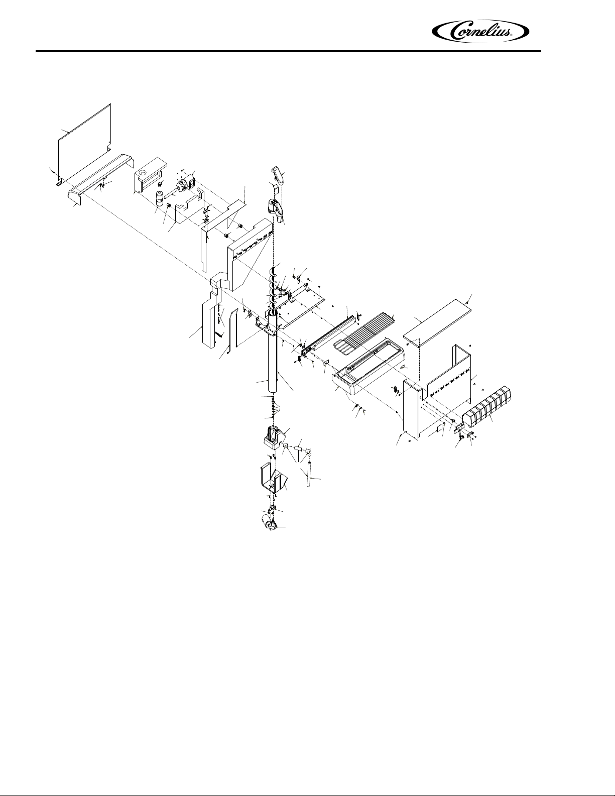
ILLUSTRATED PARTS LIST
35
Publication Number: 620918702 - 22 - © 2001-2014, Cornelius Inc.
101
12
Page 27
145
5
63
91
140
124
126
65
125
84
124
138
120
72
119
25
27
37
38
7
39
29
104
113
24
113
65
111
26 32
95
95
52
53
102
123
36
95
22
95
44
100
70
35
47
35
36
30
95
130
69 20 18 19 97
95
51
146
146
148
147
157
152
155
158
156
149
157
157
159
157
154
156 151
157
153
160 161
PR150 BC Ice Drink Dispenser Operator’s Manual
107
73
81445
©2001-2014, Cornelius Inc. - 23 - Publication Number: 620918702
Page 28
PR150 BC Ice Drink Dispenser Operator’s Manual
67
56
68
55
74
57
71
54
66
61
60
81
62
76
64
43
108
49
50
46
28
15
36
135
35
35
36
23
144
129
36
Publication Number: 620918702 - 24 - © 2001-2014, Cornelius Inc.
Page 29
PR150 BC Ice Drink Dispenser Operator’s Manual
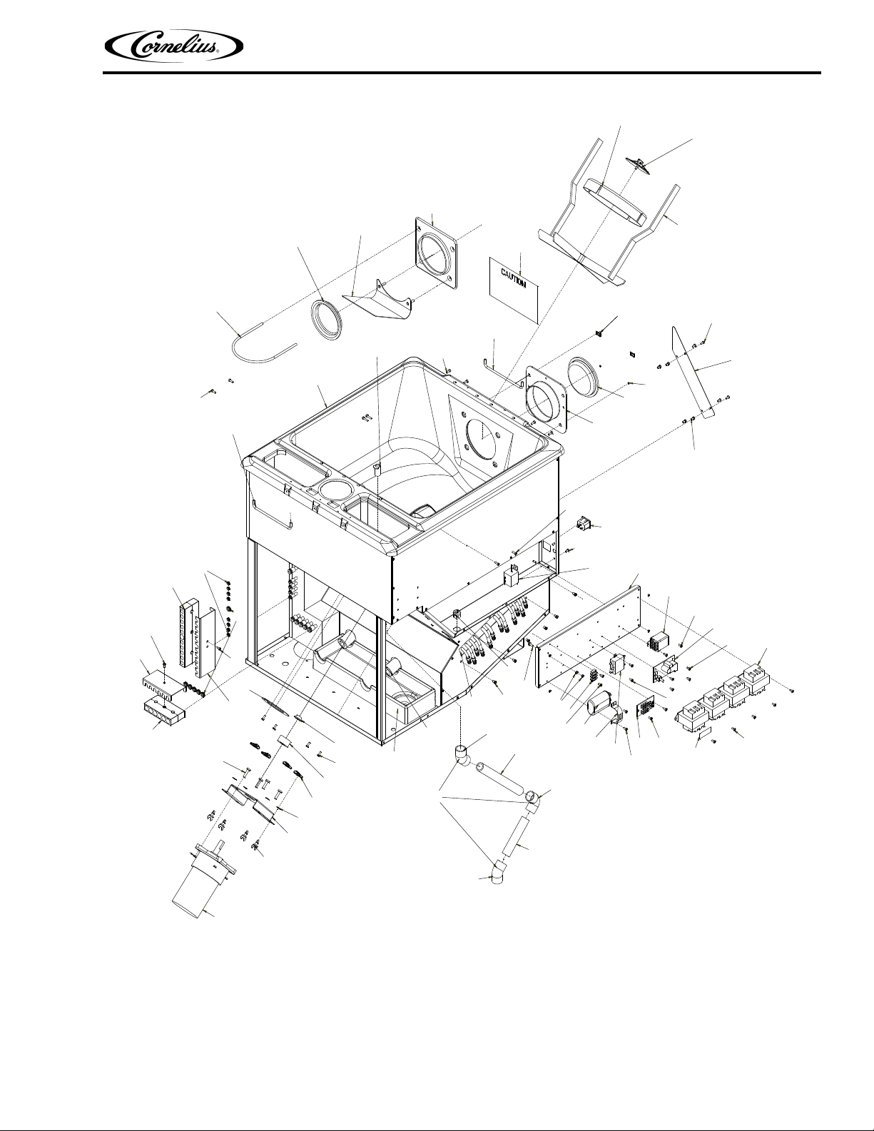
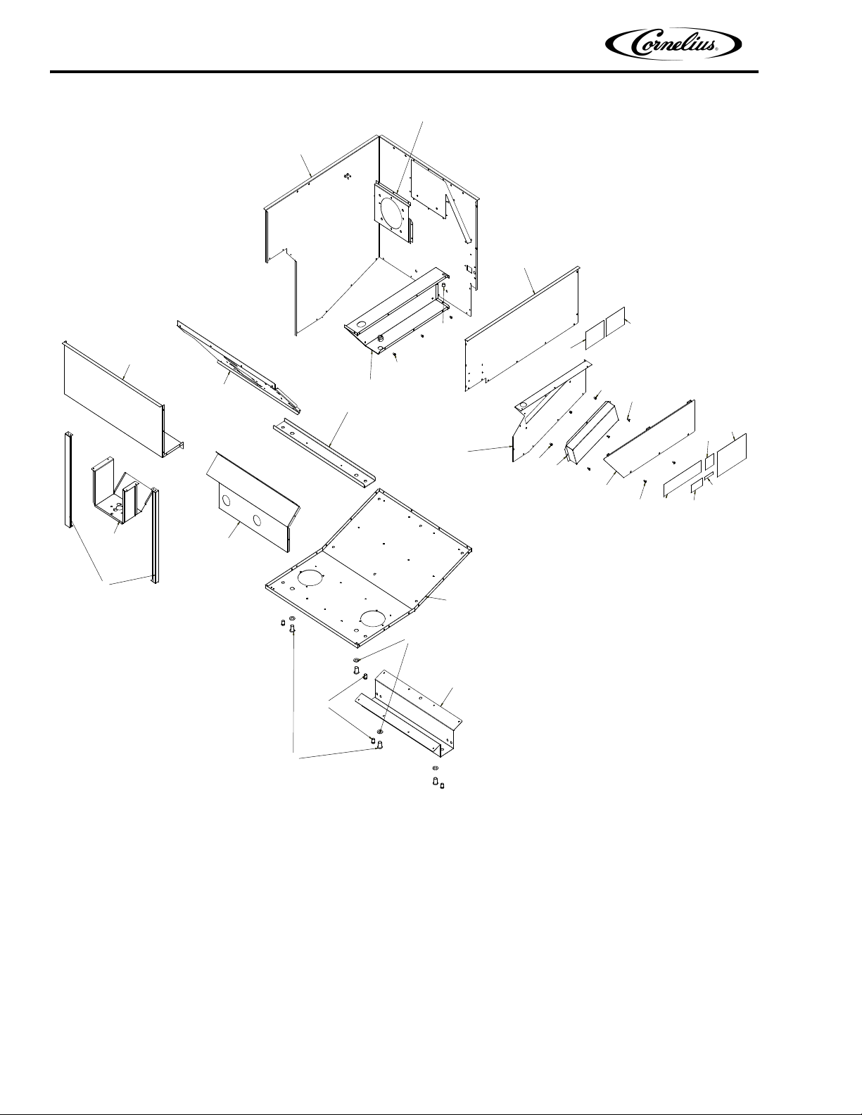
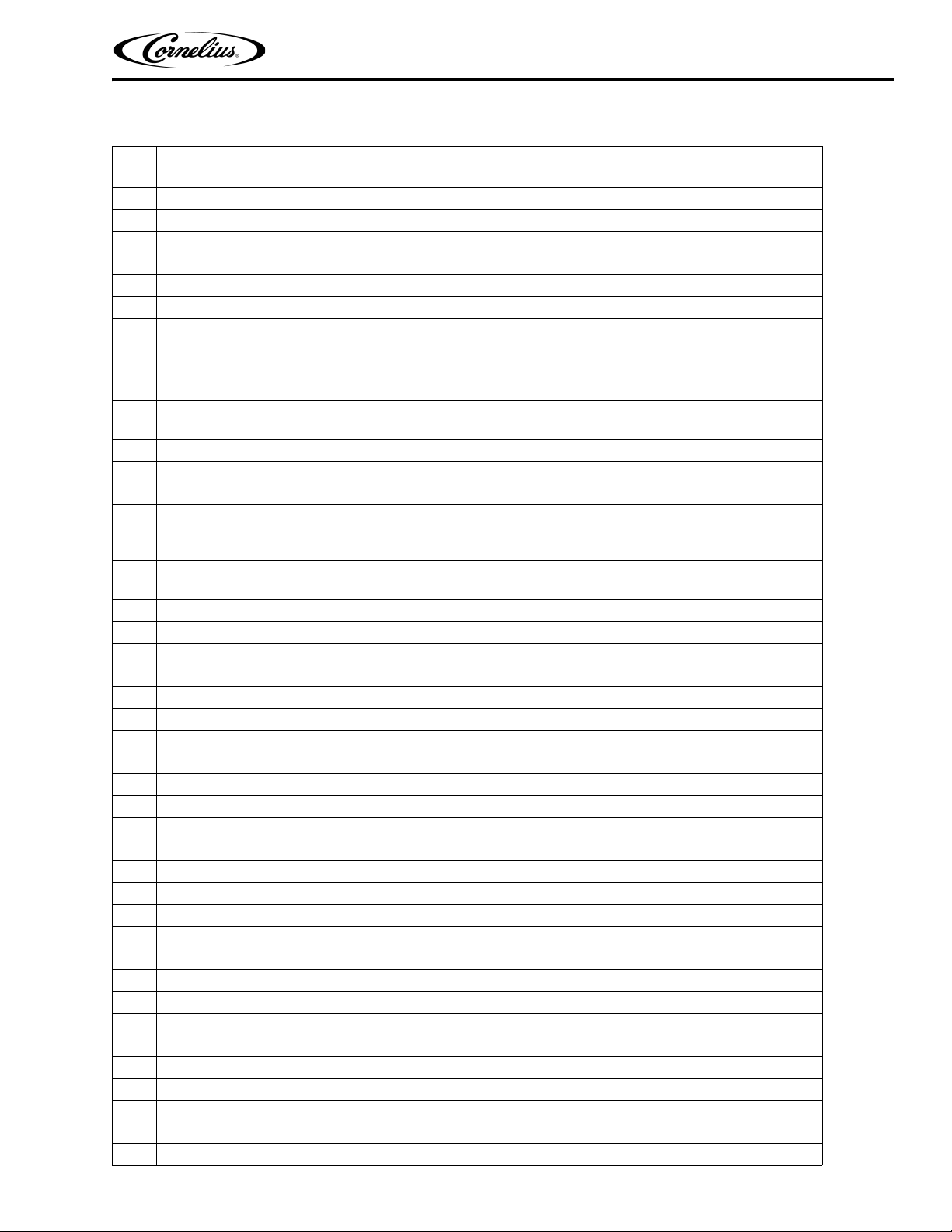
PR150BC ASSEMBLY
Item
Part No. Name
No.
1 1919 Mounting Block Ass’y, UF–1
2 1950 Cover, Valve, Back
3 1951 Cover, Valve, Front
4 1966 Dispensing Valve
5 15087 Retainer, Agitatotr
6 27107 Retainer, Ice Lever
7 29303R Plate, Motor Mount
8
9 02070 Kit Switch, includes switch, boot, and spacer
10
11 31007 Boot, Switch
12 31827 Wire Harness, Dispensing Valve
13 31981 Actuator
14
15
16 32953 Reed Switch Ass’y
17 32977 Switch, Key
18
19
20
21
22 50458 Strain Relief
23 50573 Snap Bushing, .375 I.D.
24 50951 Fitting, Elbow
25 51859 Seal, Motor Shaft
26 52132 Adhesive, Locktite
27 52876 Gasket, Motor Shaft
28 620911202 Label, Operate Auger Speed
29 70018 Hex Nut, 1/4–20 Keps
30 70023 Hex Nut, No. 4–40 STCA Keps
31 70048 Washer, .449 I.D.
32 70260 Machine Screw, Phil Rd Hd, 1/4–20 By 1–In. Long
33 70320 Pop Rivet, 125 Dia.
34 70847 Spacer, Switch
35 70894 Machine Screw, Phil Truss Hd, No. 8–32 By 3/4–In. Long
36 70959 Nut, No. 8–32
37 70992 Receptacle, 1/4 Turn
38 70993 Retainer, 1/4 Turn
39 70994 Stud, Wing Hd, 1/4 Turn
40 71028 Bolt, 1/4–20
41 720509208 Fitting, Push Connector, 3/8 By 3/8–NPTF
30794
32826
30995
620302901
620307901
32824
620913101
620919341
Heater, Agitator Motor, 115v
Heater, Agitator Motor, 230v
Cord Ass’y, 115v
Cord Ass’y, 230v
Gear Motor Kit, 115/120V 50/60HZ, includes motor, seal gasket, and
hardware
Gear Motor, 230v 50/60HZ
Label, Wiring 115v
Label, Wiring 230v
©2001-2014, Cornelius Inc. - 25 - Publication Number: 620918702
Page 30
PR150 BC Ice Drink Dispenser Operator’s Manual
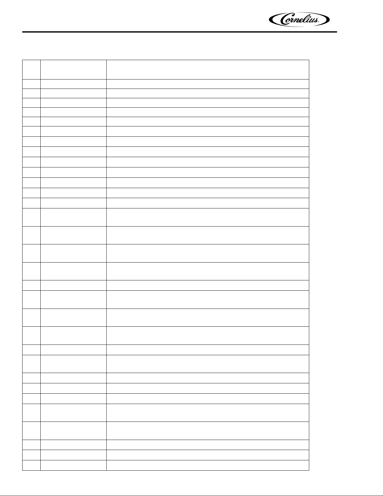
PR150BC ASSEMBLY (CONT’D)
Item
Part No.
No.
42 750700502 Clip, Locking, 3/8
43 620919303 Label, Wiring Ladder
44 638009387 Switch, Bin Control
45 90432 Label, Warning, Disconnect
46 90580 Label, Identification Data
47 90629 Label, Clean Hopper
48 91486 Medallion, Cornelius Logo
49 91956 Label, Warning Chiller Disconnect
50 92067 Label, Operation, Agitation Timer
51 92305 Label, Notice Transformer
52 31525003 O–Ring, .239 I.D. By .070 CS
53 31525017 O–Ring, .426 I.D. By .070 CS
54 620028201 Base, Cabinet
55
56
57
58
59 620028211 Cover, Tower Top
60
61
62
63 620028218 Agitator Ass’y
64
65 620028226 Bolt, 1/4–20
66 620028227 Bracket, Leg Adapter
67 620028232 Support Bracket, Auger Motor
68
69
70 620028223 Plate, Mounting
71 620028246 Stiffener, Base
72 620028249 Plate, Syrup Lines Alignment
620028202
620028252
620028204
620028269
620028205
620028254
620028209
620028256
620028213
620028255
620028214
620028257
620028216
620028258
620028222
620028261
620028234
620028263
620028235
620517201
Name
Plate, Motor Mount LH
Plate, Motor Mount RH
Cover, Access LH
Cover, Access RH
Wrap, Cabinet LH
Wrap, Cabinet RH
Tower, Valve Mounting LH
Tower, Valve Mounting RH
Wrap, Cabinet, Front LH
Wrap, Cabinet, Front RH
Electrical Box LH
Electrical Box RH
Panel, Base LH
Panel, Base RH
Cover, Electrical Box LH
Cover, Electrical Box RH
Bracket, Lower Motor Mount LH
Bracket, Lower Motor Mount RH
Hopper Ass’y LH
Hopper Ass’y RH
Publication Number: 620918702 - 26 - © 2001-2014, Cornelius Inc.
Page 31
PR150 BC Ice Drink Dispenser Operator’s Manual
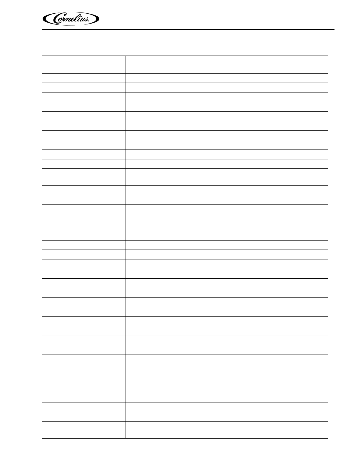
PR150BC ASSEMBLY (CONT’D)
Item
No.
Part No.
73 620028250 Plate, Water Lines Alignmen
74 620028253 Bracket, Auger Motor Mount, Right–Hand
75 620028270 Plate, Auger Motor Spacing
76 620028282 Cover, Inlet Lines
77 620906404 Label, Ice Notice
78 620043104 End Cap, Hinge, Left–Hand
79 620043105 End Cap, Hinge, Right–Hand
80 620043201 Insulation Box Foamed
81 620043206 Icemaker Sleeve Mounting Box
82 620043507 Lid, Ice Fill, Back
83
84 620044614 Plate, Deflector
85
86 620045301 Bracket, Reed Switch
87
88 620045904 Bracket, Dispense Switch
89 620045958 Bracket Ass’y, Interlock Switch
90 620046005 Cover, Reservoir
91 620046017 Cover, Bin Thermostat
92 620048102 Panel, Tower, Back
93 70076 Hex Nut, Keps, No. 8–32
94 70188 Screw, Knurled Hd, No. 8–32
95 70204 Screw, Self–Tapping, No. 8–32
96
97 620711401 Insulation, Stop Ice Conduit
98 629088578 SuperSeal Kit
99
100 620314201 Connector, Power Inlet
101
102
103 620403008 Pump, Recirculating
104 629087415 Drain Tray with Elbow Kit
105
620044601
620044602
620045724
620045727
629087456
629087489
620403001
620403002
620407601
620407622
Name
Plate, Pump Mounting LH
Plate, Pump Mounting RH
Base, Tower LH
Base, Tower RH
SuperSeal Upgrade Kit - units built before 2/02/2001 (Includes Motor, Seals, and
Motor Housing)
Motor and SuperSeal Asy Kit - units built after 2/01/2001 (Includes Motor and
Seals)
Cold Plate LH
Cold Plate RH
Coil Pack Ass’y LH
Coil Pack Ass’y RH
©2001-2014, Cornelius Inc. - 27 - Publication Number: 620918702
Page 32
PR150 BC Ice Drink Dispenser Operator’s Manual
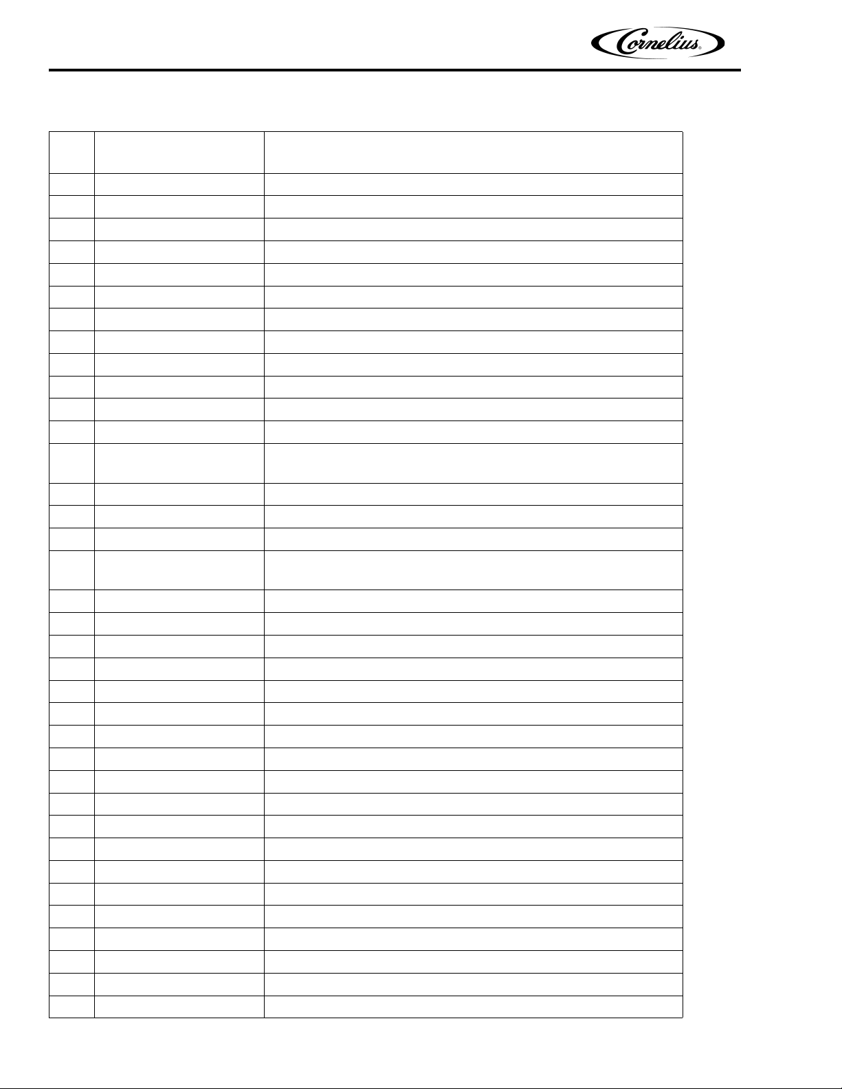
PR150BC ASSEMBLY (CONT’D)
Item
Part No.
No.
106 620407801 Fitting, Nipple, 1/2 By 1/2 NPTF
107 620503801 Agitator, Disk
108 620918901 Label, Plumbing
109 620504001 Ice Chute
110 620504002 Cover, Ice Chute
111 620504006 Seal, Hopper Conduit
112 620504011 Gate, Auger
113 620504021 Fitting, Elbow
114 620505502 Auger
115 620505703 Tube Ass’y, Auger, Front
116 620505704 Tube Ass’y, Auger, Back
117 620506512 Reservoir, Recirculating
118
119 620506518 Block, Connector, Water Lines
120 620506519 Block, Connector, Syrup Lines
121 620506531 Housing, Auger
122 620517136
123
124 620516602 Cover, Icemaker Sleeve
125 620517501 Collar, Icemaker Sleeve
126 620517601 Sleeve, Icemaker
127 620202849 Propylene Glycol
128 620700602 Sheet Metal Screw, Phil Rd Hd, No. 10–16 By 1–In. Long
129 620701123 Washer, 9/16 I.D.
130 620718101 Strainer, Drip Tray
131 620704603 Coupling
132 620704604 Fitting, 3/8 By 1/2 MPT
133 620708524 Cup Rest
134 620705201 Pushon Nut, 3/16
135 620705401 Insert Nut, 1/2–13
136 620705501 Retainer, Ice Chute Holddown
137 620708202 Plug
138 620708908 Tube, Bin Stat
139 620709301 Lever, Ice
140 620709601 Clip, Pushon
141 620709604 Clip, Back Lid, Left–Hand
620506513
620506538
620517138
Name
Hinge, Drain Trough LH
Hinge, Drain Trough RH
Drip Tray Ass’y Black, LH
Drip Tray Ass’y Black, RH
Publication Number: 620918702 - 28 - © 2001-2014, Cornelius Inc.
Page 33
PR150 BC Ice Drink Dispenser Operator’s Manual
PR150BC ASSEMBLY (CONT’D)
Item
Part No.
No.
142 620707605 Clip, Back Lid, Right–Hand
143 620709901 Pop Rivet, 125 Dia.
144 620710201 Insert, 3/8–16
145 620710301 Stop, Insulation Foam Inlets
146 50336 PVC Pipe, 3/4
147 30514
620045302
148 30774
620314301
149 31107 Terminal Board
150 33617 Wire Harness, Agitator Motor
151 449999999
560002114
152 70223 Screw, No. 10–32 By 3/4–In. Long
153 33082 Relay
154 620311701
620311702
155 70015 Hex Nut, No. 10–32
156 70147 Sheet Metal Screw, Phil Rd Hd, No. 6 By 1/2–In. Long
157 70217 Sheet Metal Screw, No. 8 By 1/2–In. Long
158 32244 Terminal Board, 230V only
159 620307301 Filter
160 50158R Armaflex
161 50326 Armaflex Tape
162 620307301 Filter RFI 230v only
163 620304601 Varistor Ass’y 230v only
164 629087412 6” Leg Kit (Not Shown)
165 629087430 Interlock Switch Bracket Kit (Not Shown)
166 70739 Key, Keyswitch Replacement (Not Shown)
Name
Strap, Capacitor 115V
Strap, Capacitor 230V
Capacitor, Agitator Motor 115v
Capacitor, Agitator Motor 230v
Transformer, 120V 60HZ
Transformer, 230V 60HZ
Timer, Agitator 115V
Timer, Agitator 230V
©2001-2014, Cornelius Inc. - 29 - Publication Number: 620918702
Page 34

PR150 BC Ice Drink Dispenser Operator’s Manual
Publication Number: 620918702 - 30 - © 2001-2014, Cornelius Inc.
Page 35

Page 36

Cornelius Inc.
www.cornelius.com
 Loading...