

Cornelius QLT180/1000-1, QLT180/1002-1, QLT180/1001-1 Installation & Service Manual
INSTALLATION
&
SERVICE
MANUAL
MODEL
QLT180/1000-1,
1002-1, & 1001-1
IMI
CORNELIUS INC.
One Cornelius Place
Anoka,
MN
55303
Tel:
1-800-238-3600 / 763-421 -61 20
Fax:
763-422-3226
Part
No.
8531 2001
Revision-
C
July
22,2002
Installation & Service Manual
SEMI-ANNUAL
"
CAUTION: The following procedures require removal of the dispenser side
panel
(8).
Disconnect the power cord from the receptacle prior to proceed-
A
ing.
0
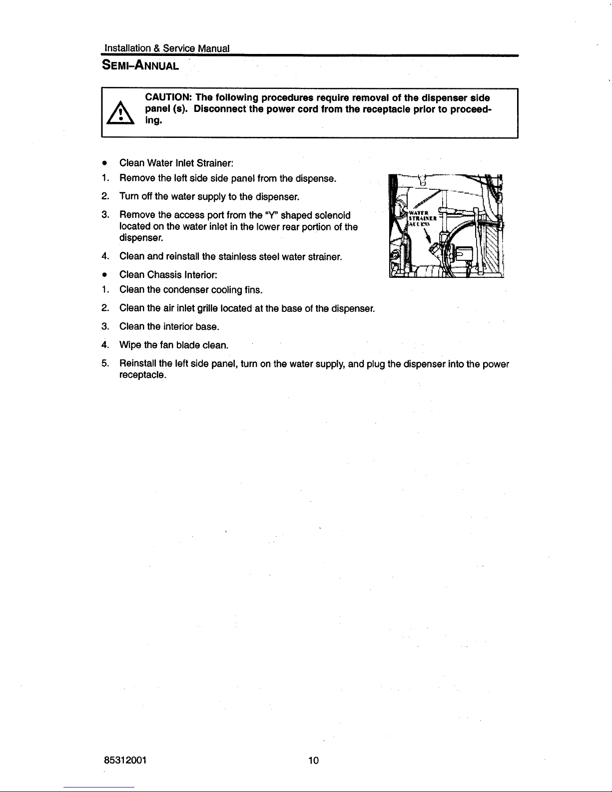
Clean Water Inlet Strainer:
1.
Remove the left side side panel from the dispense.
2.
Turn
off
the water supply to the dispenser.
3.
Remove the access port from the
"Y"
shaped solenoid
located on the water inlet in the lower rear portion
of
the
dispenser.
4.
Clean and reinstall the stainless steel water strainer.
0
Clean Chassis Interior:
1.
Clean the condenser cooling fins.
2.
Clean the air inlet grille located at the base
of
the dispenser.
3.
Clean the interior base.
4.
Wipe the fan blade clean.
5.
Reinstall the left side panel, turn on the water supply, and plug the dispenser into the power
receptacle.
8531
2001
10
Installation & Service Manual
TROU
BLE-SHOOTING
GUIDE
The following pages contain trouble-shooting information intended to aid an experienced service
person in diagnosing any operational problems that may occur.
If
you are unable to resolve the
problem after several attempts, contact the IMI Cornelius
/
Wilshire Inc. Technical Services department at 1-800-238-3600 (763-421-6120 outside the United States) between the hours of
8:OO AM and
300
PM Central Standard Time. You must have the model and serial number
(lo-
cated on the right side of the dispenser) prior to calling.
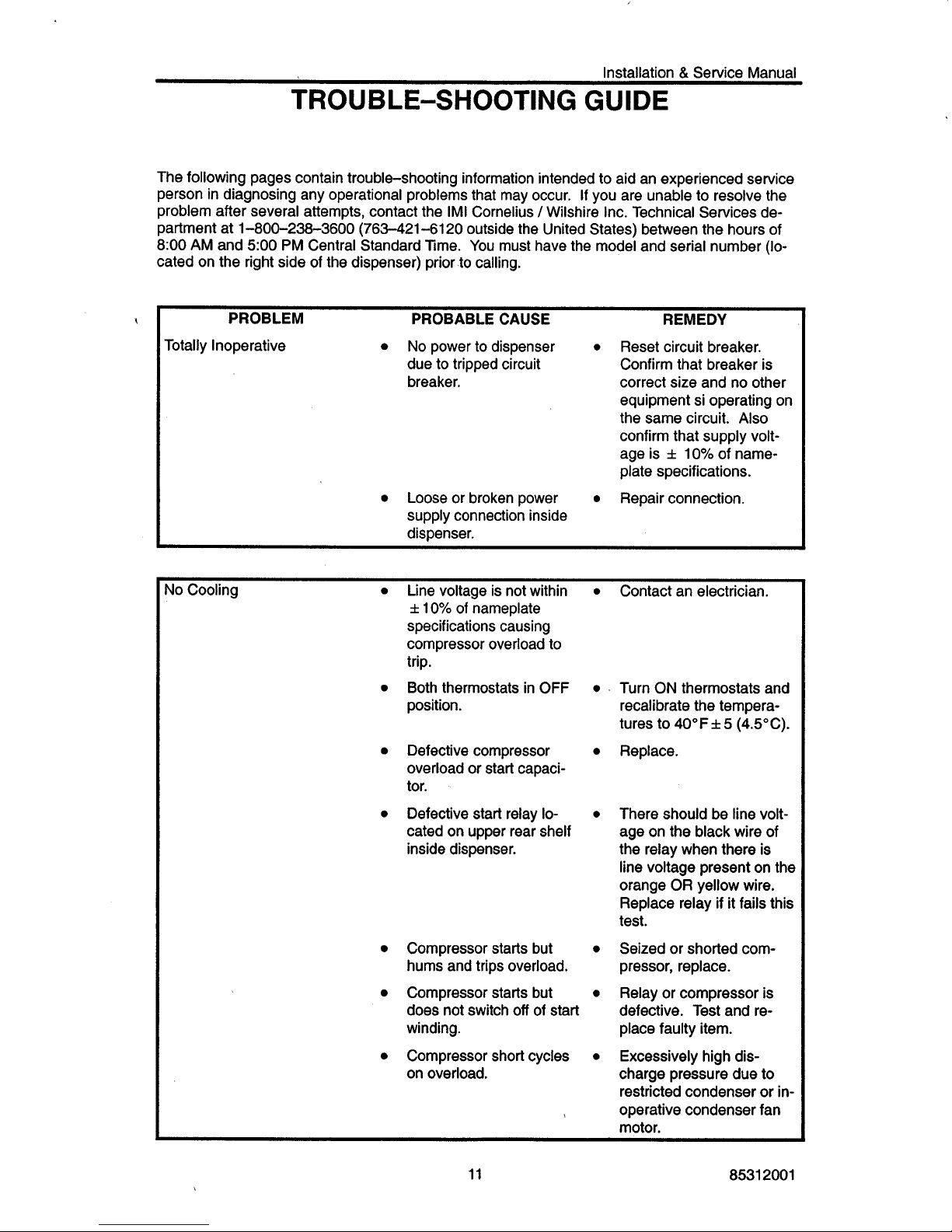
PROBLEM PROBABLE CAUSE REMEDY
due to tripped circuit
breaker.
Totally Inoperative
No
power to dispenser
0
Reset circuit breaker.
Confirm that breaker is
correct size and no other
equipment si operating on
the same circuit.
Also
confirm that supply voltage is
f
10% of name-
plate specifications.
0
Loose or broken power
0
Repair connection.
supply connection inside
dispenser.
Yo
Cooling
Line voltage is not within
f
10%
of
nameplate
specifications causing
compressor overload to
trip.
Both thermostats in
OFF
0
position.
0
Defective compressor
0
overload or start capacitor.
Defective start relay
lo-
0
cated on upper rear shelf
inside dispenser.
Compressor starts but
0
hums and trips overload.
Compressor starts but
0
does not switch
off
of
start
winding.
Compressor short cycles
0
on overload.
Contact an electrician.
Turn
ON
thermostats and
recalibrate the temperatures to
40°F f 5
(45°C).
Replace.
There should
be
line voltage on the black wire of
the relay when there is
line voltage present
on
the
orange
OR
yellow wire.
Replace relay
if
it fails this
test.
Seized or shorted com-
pressor, replace.
Relay or compressor is
defective. Test and replace faulty item.
Excessively high discharge pressure due to
restricted condenser or
in-
operative condenser fan
motor.
11 8531 2001
Installation & Service Manual
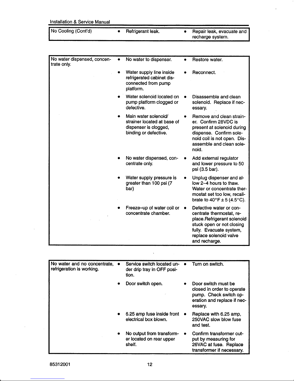
No Cooling (Cont'd)
0
Refrigerant leak.
0
Repair leak, evacuate and
recharge system.
Yo
water dispensed, concen-
0
trate only.
0
0
No
watertodispenser.
0
Water supply line inside
0
refrigerated cabinet dis-
connected from pump
platform.
Water solenoid located on
0
pump platform clogged or
defective.
Main water solenoid
0
strainer located at base of
dispenser is clogged,
binding or defective.
No
water dispensed, con-
0
centrate only.
Water supply pressure is
0
greater than
100
psi
(7
bar)
Freeze-up of water coil or
0
concentrate chamber.
Restore water.
Reconnect.
Disassemble and clean
solenoid. Replace
if
nec-
essary.
Remove and clean strain-
er. Confirm 28VDC is
present at solenoid during
dispense. Confirm solenoid coil is not open. Disassemble and clean solenoid.
Add external regulator
and lower pressure to
50
psi
(3.5
bar).
Unplug dispenser and al-
low 2-4 hours to thaw.
Water or concentrate thermostat set too low, recalibrate to 40" F
f
5
(4.5"C).
Defective water or concentrate thermostat, replace. Refrigerant solenoid
stuck open or not closing
fully. Evacuate system,
replace solenoid valve
and recharge.
No
water and no concentrate,
0
Service switch located un-
0
Turn on switch.
refrigeration is working.
der drip tray in OFF position.
0
Door switch open.
0
Door switch must be
closed
in
order to operate
pump. Check switch operation and replace
if
nec-
essary.
0
6.25 amp fuse inside front
0
Replace with 6.25 amp,
25OVAC
slow
blow fuse
and test.
0
No output from transform-
0
Confirm transformer out-
er located on rear upper put by measuring for
shelf. 26VAC at fuse. Replace
transformer
if
necessarv.
electrical
box
blown.
8531 2001
12
Installation & Service Manual
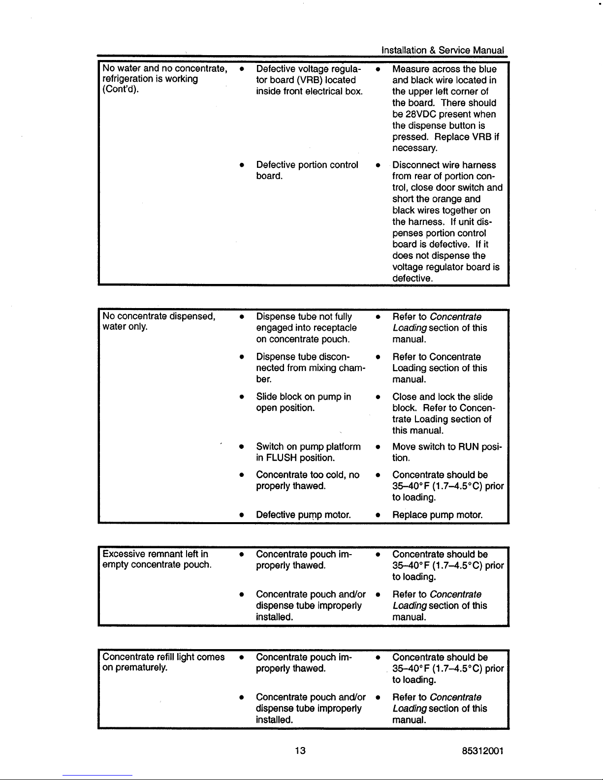
No water and no concentrate,
0
Defective voltage regula-
0
Measure across the blue
refrigeration is working
and black wire located in
(Cont'd). inside front electrical box. the upper left corner of
the board. There should
be 28VDC present when
the dispense button is
pressed. Replace VRB
if
necessary.
0
Defective portion control
0
Disconnect wire harness
from rear of portion control, close door switch and
short the orange and
black wires together on
the harness.
If
unit dispenses portion control
board
is
defective.
If
it
does not dispense the
voltage regulator board is
defective.
tor board (VRB) located
board.
No
concentrate dispensed,
0
Dispense tube not fully
0
Refer to
Concentrate
water only.
engaged into receptacle
Loading
section of this
on concentrate pouch. manual.
nected from mixing chamber. manual.
open position.
0
Dispense tube discon-
0
Refer to Concentrate
Loading section of this
0
Slide block on pump in
0
Close and lock the slide
block. Refer to Concentrate Loading section of
this manual.
'
Switch on pump platform
0
Move switch to RUN posi-
0
Concentrate too cold, no
0
Concentrate should be
in FLUSH position. tion.
properly thawed. 3540°F (1.74.5"C) prior
to loading.
I
0
Defective pump motor.
0
Replace pump motor.
Excessive remnant left in
0
Concentrate pouch im-
0
Concentrate should be
empty concentrate pouch. properly thawed.
3540°F (1.7-4.5"C) prior
to loading.
Loading
section of this
0
Concentrate pouch and/or
0
Refer to
Concentrate
dispense tube improperly
installed. manual.
Concentrate refill light comes
0
Concentrate pouch im-
0
Concentrate should
be
on prematurely.
properly thawed. 3540°F (1.7-4.5"C) prior
to loading.
Loading
section of this
0
Concentrate pouch andlor
0
Refer to
Concentrate
dispense tube improperly
installed. manual.
_____
13 8531 2001
Installation & Servicg Manual
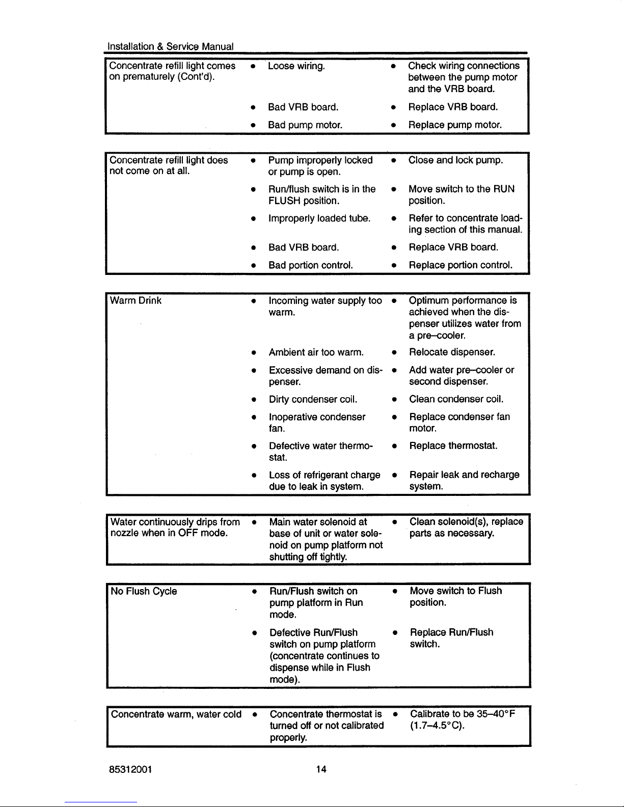
Concentrate refill light comes
0
Loose wiring.
0
Check wiring connections
on prematurely (Cont'd).
between the pump motor
and the VRB board.
0
Bad VRB board.
0
Replace VRB board.
I
0
Bad pump motor.
0
Replace pump motor.
I
Concentrate refill light does
0
Pump improperly locked
0
Close and lock pump.
not come on at all.
or pump is open.
FLUSH position. position.
0
Run/flush switch is in the
0
Move switch to the RUN
0
Improperly loaded tube.
0
Refer to concentrate loading section of this manual.
0
Bad VRB board.
0
Replace VRB board.
0
Bad portion control.
0
Replace portion control.
Warm Drink
0
Incoming water supply too
0
Optimum performance is
warm. achieved when the dis-
penser utilizes water from
a pre-cooler.
0
Ambient air too warm.
0
Relocate dispenser.
0
Excessive demand on dis-
0
Add water pre-cooler or
penser.
second dispenser.
0
Dirty condenser coil.
0
Clean condenser coil.
I
I
0
Inoperative condenser
0
Replace condenser fan
0
Defective water thermo-
0
Replace thermostat.
0
Loss of refrigerant charge
0
Repair leak and recharge
fan. motor.
stat.
due to leak in system.
system.
Water continuously drips from
0
Main water solenoid at
0
Clean solenoid(s), replace
nozzle when in OFF mode.
base of unit or water solenoid on pump platform not
shutting
off
tightly.
parts as necessary.
No
Flush Cycle
0
Run/Flush switch on
0
Move switch to Flush
pump platform
in
Run position.
mode.
switch on pump platform switch.
(concentrate continues to
dispense while in Flush
mode).
0
Defective Run/Flush
0
Replace Run/Flush
Concentrate warm, water cold
0
Concentrate thermostat is
0
Calibrate to be 3540°F
turned
off
or not calibrated
properly.
(1 -7-4.5"C).
8531 2001 14
Installation & Service Manual
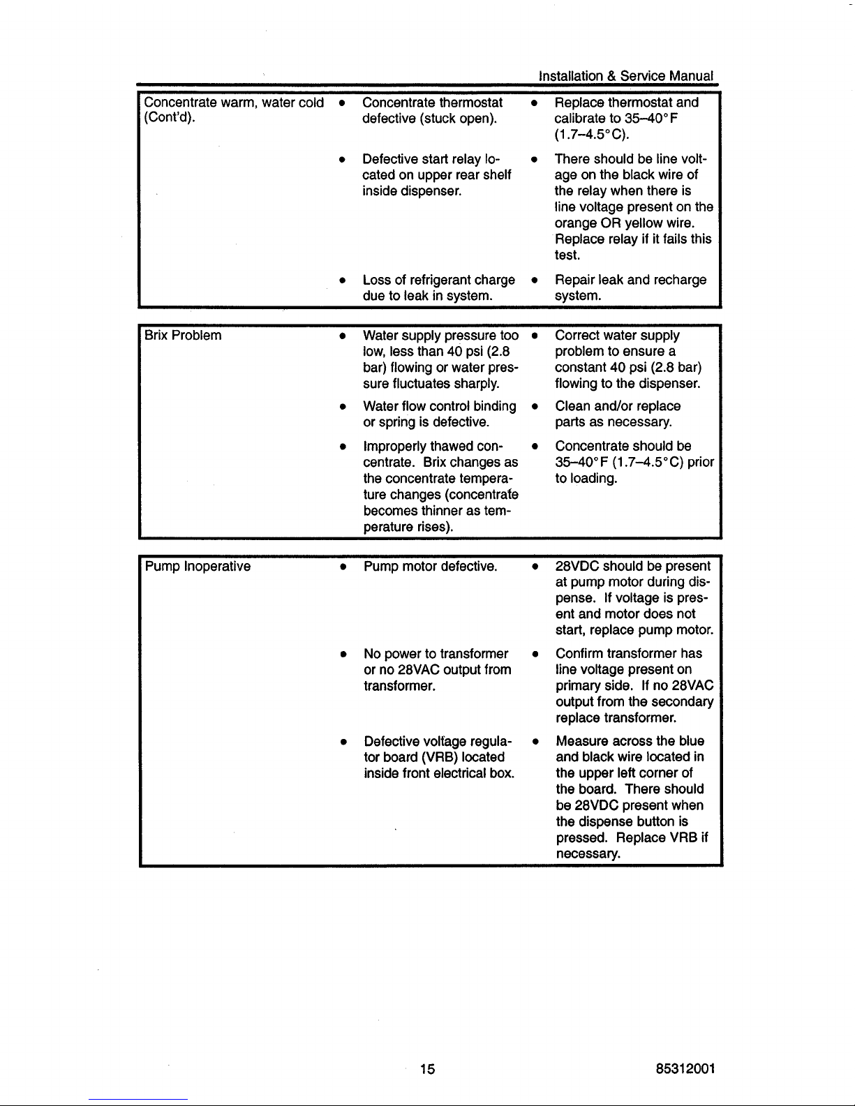
Concentrate warm, water cold
0
Concentrate thermostat
0
Replace thermostat and
(Cont'd).
defective (stuck open). calibrate to 3540°F
(1.7-4.5"C).
0
Defective start relay
lo-
0
There should be line voltcated on upper rear shelf
inside dispenser.
age on the black wire of
the relay when there is
line voltage present on the
orange
OR yellow wire.
Replace relay
if
it fails this
test.
0
Loss of refrigerant charge
0
Repair leak and recharge
system. due to leak in system.
Brix Problem
0
Water supply pressure too
0
Correct water supply
problem to ensure a
constant
40
psi (2.8 bar)
flowing to the dispenser.
parts as necessary.
3540°F (1.74.5"C) prior
low, less than 40 psi (2.8
bar) flowing or water pressure fluctuates sharply.
or spring is defective.
centrate. Brix changes as
the concentrate tempera- to loading.
ture changes (concentrate
becomes thinner as temperature rises).
0
Water flow control binding
0
Clean and/or replace
0
Improperly thawed con-
0
Concentrate should be
Pump Inoperative
0
Pump motor defective. 28VDC should be present
0
No power to transformer
or no 28VAC output from
transformer.
0
Defective voltage regulator board (VRB) located
inside front electrical box.
at pump motor during dispense.
If
voltage is present and motor does not
start, replace pump motor.
Confirm transformer has
line voltage present on
primary side. If no 28VAC
output from the secondary
replace transformer.
Measure across the blue
and black wire located
in
the upper
left
corner of
the board. There should
be 28VDC present when
the dispense button is
pressed. Replace VRB
if
necessary.
15
8531 2001
Installation & Service Manual
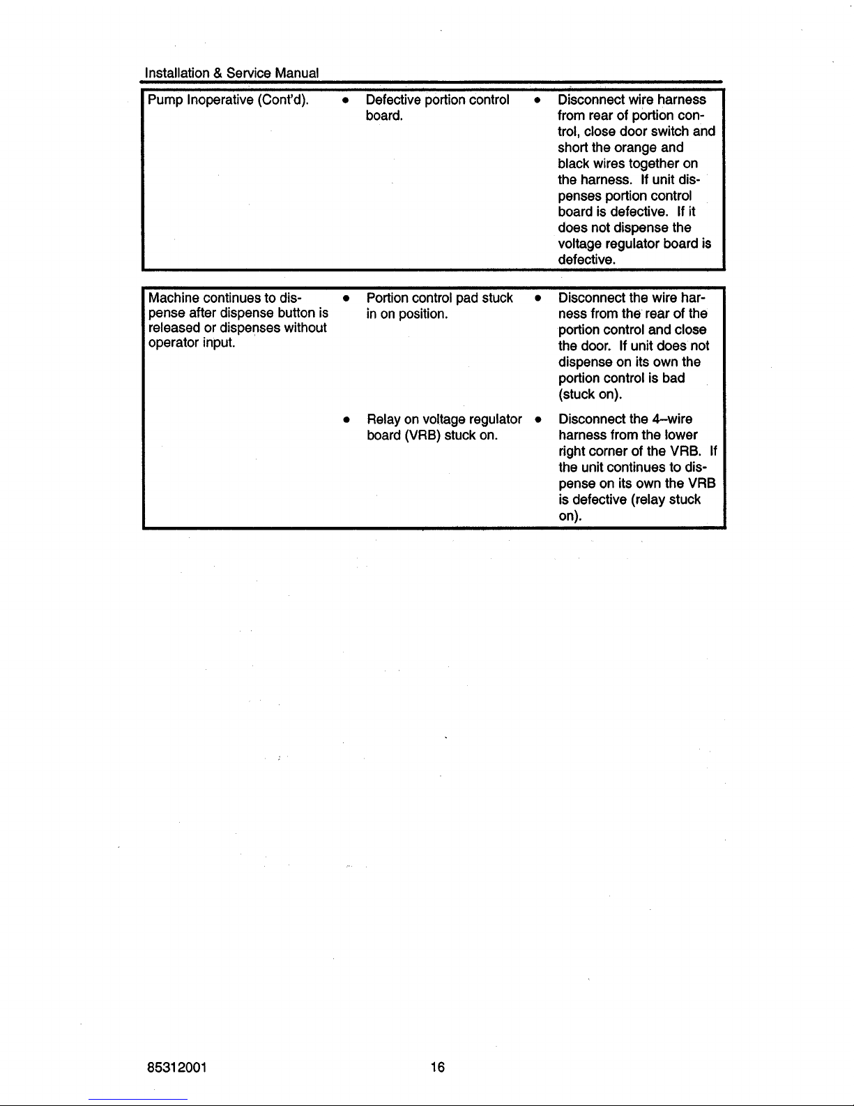
Pump Inoperative (Cont’d).
0
Defective portion control
0
Disconnect wire harness
from rear of portion control, close door switch and
short the orange and
black wires together on
the harness.
If
unit dispenses portion control
board is defective.
If
it
does not dispense the
voltage regulator board is
defective.
board.
Machine continues to dis-
0
Portion control pad stuck
0
Disconnect the wire har-
pense after dispense button is
ness from the rear of the
released or dispenses without
portion control and close
operator input.
the door. If unit does not
dispense on its own the
portion control is bad
(stuck on).
0
Relay on voltage regulator
0
Disconnect the &wire
harness from the lower
right corner of the VRB.
If
the unit continues to dis-
pense on its own the VRB
is defective (relay stuck
on).
in on position.
board (VRB) stuck on.
8531
2001
16
Installation
&
Service
Manual
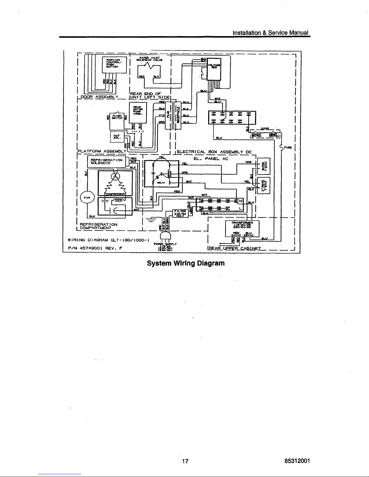
System
Wiring
Diagram
17
8531
2001
Installation & Service Manual
0
0
0
0
0
0
0
0
0
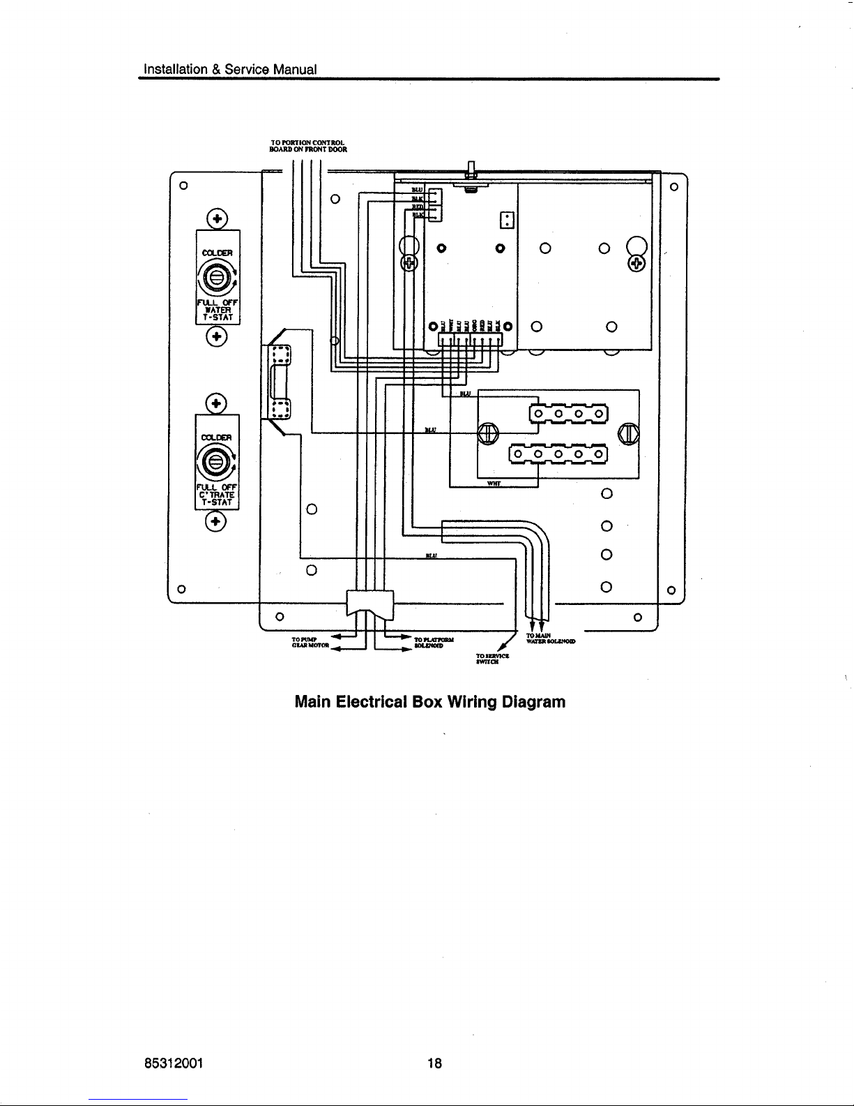
Main Electrical
Box
Wiring Diagram
8631 2001
18
Installation & Service Manual
45551
455381
00
455091
000
451 55001
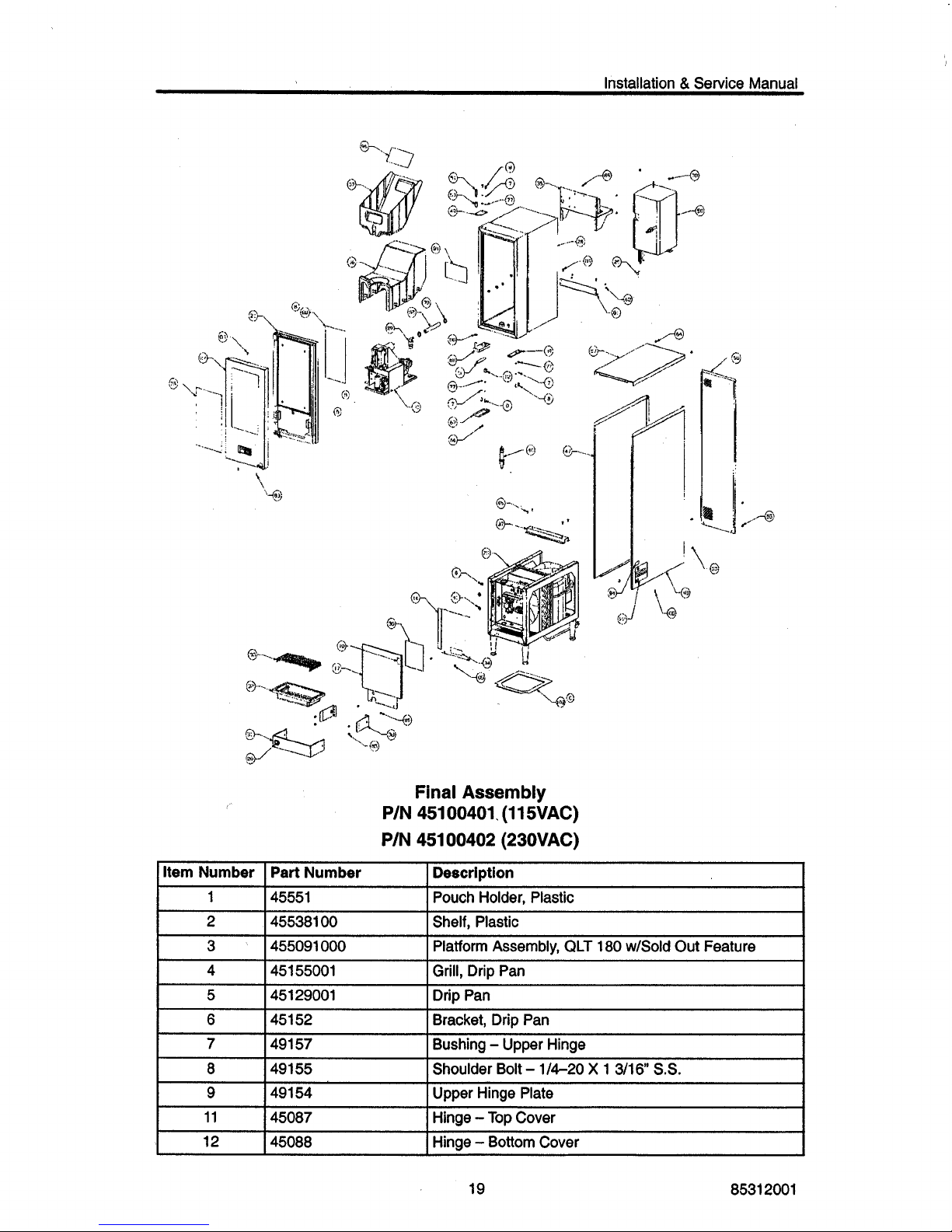
Final
Assembly
P/N
45100401. (115VAC)
P/N
451 00402 (23OVAC)
Pouch Holder, Plastic
Shelf, Plastic
Platform
Assembly,
QLT
180
w/Sold
Out Feature
Grill, Drip Pan
I
1
451 52
491 57
I
Item Number
Bracket, Drip Pan
Bushing
-
Upper Hinge
I
6
Part Number
I
Description
I
451 29001
I
Drip Pan
I
I
49155
I
Shoulder Bolt - 1/4-20 X 1 3/16 S.S.
1
I
49154
I
Upper Hinge Plate
I
..
-
45087
I
Hinge - Top Cover
I
45088
I
Hinge - Bottom Cover
I
19 85312001
 Loading...