

Cornelius pbd175 Service Manual
PBD175 (SPIRE 3.0)
Service Manual
Release Date: September 01, 2015
Publication Number: 620062609SER
Revision Date: September 06, 2016
Revision: D
Visit the Cornelius web site at www.cornelius.com
for all your Literature needs.

The products, technical information, and instructions contained in this manual are subject to change without notice.
RECYCLE
These instructions are not intended to cover all details or variations of the equipment, nor to provide for every possible contingency in the installation, operation or maintenance of this equipment. This manual assumes that the person(s) working on the equipment have been trained and are skilled in working with electrical, plumbing, pneumatic,
and mechanical equipment. It is assumed that appropriate safety precautions are taken and that all local safety and
construction requirements are being met, in addition to the information contained in this manual.
This Product is warranted only as provided in Cornelius’ Commercial Warranty applicable to this Product and is subject to all of the restrictions and limitations contained in the Commercial Warranty.
Cornelius will not be responsible for any repair, replacement or other service required by or loss or damage resulting
from any of the following occurrences, including but not limited to, (1) other than normal and proper use and normal
service conditions with respect to the Product, (2) improper voltage, (3) inadequate wiring, (4) abuse, (5) accident,
(6) alteration, (7) misuse, (8) neglect, (9) unauthorized repair or the failure to utilize suitably qualified and trained persons to perform service and/or repair of the Product, (10) improper cleaning, (11) failure to follow installation, operating, cleaning or maintenance instructions, (12) use of “non-authorized” parts (i.e., parts that are not 100%
compatible with the Product) which use voids the entire warranty, (13) Product parts in contact with water or the
product dispensed which are adversely impacted by changes in liquid scale or chemical composition.
Contact Information:
To inquire about current revisions of this and other documentation or for assistance with any Cornelius product contact:
www.cornelius.com
800-238-3600
Trademarks and Copyrights:
This document contains proprietary information and it may not be reproduced in any way without permission from
Cornelius.
This document contains the original instructions for the unit described.
CORNELIUS INC
101 Regency Drive
Glendale Heights, IL
Tel: + 1 800-238-3600
Printed in U.S.A.
Correct Disposal of this Product
This marking indicates that this product should not be disposed with other household wastes throughout the EU. To
prevent possible harm to the environment or human health from uncontrolled waste disposal, recycle it responsibly
to promote the sustainable reuse of material resources. To return your used device, please use the return and
collection systems or contact the retailer where the product was purchased. They can take this product for
environmental safe recycling.

PBD175 (Spire 3.0) Service Manual
TABLE OF CONTENTS
Safety Instructions. . . . . . . . . . . . . . . . . . . . . . . . . . . . . . . . . . . . . . . . . . . . . . . . . . . . . . . . . . . . . . . . . 1
Read and Follow ALL Safety Instructions . . . . . . . . . . . . . . . . . . . . . . . . . . . . . . . . . . . . . . . . . . . . . 1
Safety Overview . . . . . . . . . . . . . . . . . . . . . . . . . . . . . . . . . . . . . . . . . . . . . . . . . . . . . . . . . . . . . . 1
Recognition . . . . . . . . . . . . . . . . . . . . . . . . . . . . . . . . . . . . . . . . . . . . . . . . . . . . . . . . . . . . . . . . . 1
Different Types of Alerts . . . . . . . . . . . . . . . . . . . . . . . . . . . . . . . . . . . . . . . . . . . . . . . . . . . . . . . . . . 1
Safety Tips . . . . . . . . . . . . . . . . . . . . . . . . . . . . . . . . . . . . . . . . . . . . . . . . . . . . . . . . . . . . . . . . . . . . . 1
Qualified Service Personnel. . . . . . . . . . . . . . . . . . . . . . . . . . . . . . . . . . . . . . . . . . . . . . . . . . . . . . . . 1
Safety Precautions. . . . . . . . . . . . . . . . . . . . . . . . . . . . . . . . . . . . . . . . . . . . . . . . . . . . . . . . . . . . . . . 2
Shipping And Storage . . . . . . . . . . . . . . . . . . . . . . . . . . . . . . . . . . . . . . . . . . . . . . . . . . . . . . . . . . . . 2
CO
(Carbon Dioxide) Warning . . . . . . . . . . . . . . . . . . . . . . . . . . . . . . . . . . . . . . . . . . . . . . . . . . . . . 2
2
Pepsi PBD175 (Spire 3.0) Usage . . . . . . . . . . . . . . . . . . . . . . . . . . . . . . . . . . . . . . . . . . . . . . . . . . . 2
Decommissioning and/or Transporting the Unit. . . . . . . . . . . . . . . . . . . . . . . . . . . . . . . . . . . . . . . . . 2
Introduction . . . . . . . . . . . . . . . . . . . . . . . . . . . . . . . . . . . . . . . . . . . . . . . . . . . . . . . . . . . . . . . . . . . . . . 3
Service Manual Overview . . . . . . . . . . . . . . . . . . . . . . . . . . . . . . . . . . . . . . . . . . . . . . . . . . . . . . . . . 3
System Overview . . . . . . . . . . . . . . . . . . . . . . . . . . . . . . . . . . . . . . . . . . . . . . . . . . . . . . . . . . . . . . . . 3
Critical Component Storage Temperatures . . . . . . . . . . . . . . . . . . . . . . . . . . . . . . . . . . . . . . . . . . . . 3
Preparing The Counter . . . . . . . . . . . . . . . . . . . . . . . . . . . . . . . . . . . . . . . . . . . . . . . . . . . . . . . . . . . 4
Marking and Cutting the Counter . . . . . . . . . . . . . . . . . . . . . . . . . . . . . . . . . . . . . . . . . . . . . . . . . 4
Control Panel . . . . . . . . . . . . . . . . . . . . . . . . . . . . . . . . . . . . . . . . . . . . . . . . . . . . . . . . . . . . . . . . . . . 5
Spire Subsystems . . . . . . . . . . . . . . . . . . . . . . . . . . . . . . . . . . . . . . . . . . . . . . . . . . . . . . . . . . . . . . . 6
Computer . . . . . . . . . . . . . . . . . . . . . . . . . . . . . . . . . . . . . . . . . . . . . . . . . . . . . . . . . . . . . . . . . . . 6
Valve Assemblies. . . . . . . . . . . . . . . . . . . . . . . . . . . . . . . . . . . . . . . . . . . . . . . . . . . . . . . . . . . . . 7
LX3 Board . . . . . . . . . . . . . . . . . . . . . . . . . . . . . . . . . . . . . . . . . . . . . . . . . . . . . . . . . . . . . . . . . . 8
Valve Control Board. . . . . . . . . . . . . . . . . . . . . . . . . . . . . . . . . . . . . . . . . . . . . . . . . . . . . . . . . . . 8
Agitator/Carbonator Control Board. . . . . . . . . . . . . . . . . . . . . . . . . . . . . . . . . . . . . . . . . . . . . . . . 9
ADA Console . . . . . . . . . . . . . . . . . . . . . . . . . . . . . . . . . . . . . . . . . . . . . . . . . . . . . . . . . . . . . . . . 9
Operation . . . . . . . . . . . . . . . . . . . . . . . . . . . . . . . . . . . . . . . . . . . . . . . . . . . . . . . . . . . . . . . . . . . . . . . 10
Starting the Unit . . . . . . . . . . . . . . . . . . . . . . . . . . . . . . . . . . . . . . . . . . . . . . . . . . . . . . . . . . . . . . . . 10
Icemaker Capability . . . . . . . . . . . . . . . . . . . . . . . . . . . . . . . . . . . . . . . . . . . . . . . . . . . . . . . . . . . . . 10
Preventative Maintenance. . . . . . . . . . . . . . . . . . . . . . . . . . . . . . . . . . . . . . . . . . . . . . . . . . . . . . . . . . 11
Cleaning the PBD175 (Spire 3.0). . . . . . . . . . . . . . . . . . . . . . . . . . . . . . . . . . . . . . . . . . . . . . . . . . . 11
Daily Cleaning . . . . . . . . . . . . . . . . . . . . . . . . . . . . . . . . . . . . . . . . . . . . . . . . . . . . . . . . . . . . . . 11
Daily Maintenance . . . . . . . . . . . . . . . . . . . . . . . . . . . . . . . . . . . . . . . . . . . . . . . . . . . . . . . . . . . 12
Monthly Cleaning . . . . . . . . . . . . . . . . . . . . . . . . . . . . . . . . . . . . . . . . . . . . . . . . . . . . . . . . . . . . . . . 12
Sanitizing Syrup Lines and the BIB System. . . . . . . . . . . . . . . . . . . . . . . . . . . . . . . . . . . . . . . . 12
Entering Service Mode . . . . . . . . . . . . . . . . . . . . . . . . . . . . . . . . . . . . . . . . . . . . . . . . . . . . . . . . . . . . 14
Service Screen. . . . . . . . . . . . . . . . . . . . . . . . . . . . . . . . . . . . . . . . . . . . . . . . . . . . . . . . . . . . . . 14
NUC Power Button. . . . . . . . . . . . . . . . . . . . . . . . . . . . . . . . . . . . . . . . . . . . . . . . . . . . . . . . . . . 15
Sold Out Syrups . . . . . . . . . . . . . . . . . . . . . . . . . . . . . . . . . . . . . . . . . . . . . . . . . . . . . . . . . . . . . 16
© 2015, Cornelius Inc. Publication Number: 620062609SER

PBD175 (Spire 3.0) Service Manual
Mapping the Valves . . . . . . . . . . . . . . . . . . . . . . . . . . . . . . . . . . . . . . . . . . . . . . . . . . . . . . . . . . 16
Valve Assignment Options. . . . . . . . . . . . . . . . . . . . . . . . . . . . . . . . . . . . . . . . . . . . . . . . . . . . . 18
4 Second BRIX Calibration . . . . . . . . . . . . . . . . . . . . . . . . . . . . . . . . . . . . . . . . . . . . . . . . . . . . 18
Sanitization . . . . . . . . . . . . . . . . . . . . . . . . . . . . . . . . . . . . . . . . . . . . . . . . . . . . . . . . . . . . . . . . 19
Priming. . . . . . . . . . . . . . . . . . . . . . . . . . . . . . . . . . . . . . . . . . . . . . . . . . . . . . . . . . . . . . . . . . . . 19
View Layout . . . . . . . . . . . . . . . . . . . . . . . . . . . . . . . . . . . . . . . . . . . . . . . . . . . . . . . . . . . . . . . . 19
Actions Options . . . . . . . . . . . . . . . . . . . . . . . . . . . . . . . . . . . . . . . . . . . . . . . . . . . . . . . . . . . . . . . . 20
System Reboot Shutdown . . . . . . . . . . . . . . . . . . . . . . . . . . . . . . . . . . . . . . . . . . . . . . . . . . . . . 20
Display Power . . . . . . . . . . . . . . . . . . . . . . . . . . . . . . . . . . . . . . . . . . . . . . . . . . . . . . . . . . . . . . 20
Volume Adjustment . . . . . . . . . . . . . . . . . . . . . . . . . . . . . . . . . . . . . . . . . . . . . . . . . . . . . . . . . . 20
Sanitization . . . . . . . . . . . . . . . . . . . . . . . . . . . . . . . . . . . . . . . . . . . . . . . . . . . . . . . . . . . . . . . . 20
Adjust Water to Syrup Ratio (BRIX). . . . . . . . . . . . . . . . . . . . . . . . . . . . . . . . . . . . . . . . . . . . . . . . . 20
Define Input Flow Rates . . . . . . . . . . . . . . . . . . . . . . . . . . . . . . . . . . . . . . . . . . . . . . . . . . . . . . . . . 21
Systems Options . . . . . . . . . . . . . . . . . . . . . . . . . . . . . . . . . . . . . . . . . . . . . . . . . . . . . . . . . . . . . . . 21
Equipment Status . . . . . . . . . . . . . . . . . . . . . . . . . . . . . . . . . . . . . . . . . . . . . . . . . . . . . . . . . . . . . . 21
SEN Connections. . . . . . . . . . . . . . . . . . . . . . . . . . . . . . . . . . . . . . . . . . . . . . . . . . . . . . . . . . . . 21
System. . . . . . . . . . . . . . . . . . . . . . . . . . . . . . . . . . . . . . . . . . . . . . . . . . . . . . . . . . . . . . . . . . . . 22
Valve Controller . . . . . . . . . . . . . . . . . . . . . . . . . . . . . . . . . . . . . . . . . . . . . . . . . . . . . . . . . . . . . 22
ADA Controller . . . . . . . . . . . . . . . . . . . . . . . . . . . . . . . . . . . . . . . . . . . . . . . . . . . . . . . . . . . . . . 22
Touch Controller . . . . . . . . . . . . . . . . . . . . . . . . . . . . . . . . . . . . . . . . . . . . . . . . . . . . . . . . . . . . 22
Preventative Maintenance. . . . . . . . . . . . . . . . . . . . . . . . . . . . . . . . . . . . . . . . . . . . . . . . . . . . . . . . . . 22
Component Replacement . . . . . . . . . . . . . . . . . . . . . . . . . . . . . . . . . . . . . . . . . . . . . . . . . . . . . . . . . . 23
Removing the Cladding . . . . . . . . . . . . . . . . . . . . . . . . . . . . . . . . . . . . . . . . . . . . . . . . . . . . . . . . . . 23
Replacing the Display . . . . . . . . . . . . . . . . . . . . . . . . . . . . . . . . . . . . . . . . . . . . . . . . . . . . . . . . . . . 24
Replacing Valves . . . . . . . . . . . . . . . . . . . . . . . . . . . . . . . . . . . . . . . . . . . . . . . . . . . . . . . . . . . . . . . 27
Replacing the Backblock . . . . . . . . . . . . . . . . . . . . . . . . . . . . . . . . . . . . . . . . . . . . . . . . . . . . . . . . . 28
Computer Information and Service . . . . . . . . . . . . . . . . . . . . . . . . . . . . . . . . . . . . . . . . . . . . . . . . . 29
Computer Diagnostics . . . . . . . . . . . . . . . . . . . . . . . . . . . . . . . . . . . . . . . . . . . . . . . . . . . . . . . . 29
Replacing the Computer . . . . . . . . . . . . . . . . . . . . . . . . . . . . . . . . . . . . . . . . . . . . . . . . . . . . . . 30
Valve Control Board Information and Service . . . . . . . . . . . . . . . . . . . . . . . . . . . . . . . . . . . . . . . . . 31
Valve Control Board Diagnostics . . . . . . . . . . . . . . . . . . . . . . . . . . . . . . . . . . . . . . . . . . . . . . . . 31
Replacing the Valve Control Board . . . . . . . . . . . . . . . . . . . . . . . . . . . . . . . . . . . . . . . . . . . . . . 32
ADA Control Board Information and Service . . . . . . . . . . . . . . . . . . . . . . . . . . . . . . . . . . . . . . . . . . 33
ADA Control Board Diagnostics. . . . . . . . . . . . . . . . . . . . . . . . . . . . . . . . . . . . . . . . . . . . . . . . . 33
Replacing the ADA Control Board . . . . . . . . . . . . . . . . . . . . . . . . . . . . . . . . . . . . . . . . . . . . . . . 33
LED Spot Light Assembly . . . . . . . . . . . . . . . . . . . . . . . . . . . . . . . . . . . . . . . . . . . . . . . . . . . . . . . . 35
Replacing the LED Spot Light Assembly . . . . . . . . . . . . . . . . . . . . . . . . . . . . . . . . . . . . . . . . . . 35
Enclave Re-Install Work Instructions . . . . . . . . . . . . . . . . . . . . . . . . . . . . . . . . . . . . . . . . . . . . . . . . 36
Replacing the Carbonator Sensor . . . . . . . . . . . . . . . . . . . . . . . . . . . . . . . . . . . . . . . . . . . . . . . 40
Replacing the Ice Bin Agitator . . . . . . . . . . . . . . . . . . . . . . . . . . . . . . . . . . . . . . . . . . . . . . . . . . 41
Publication Number: 620062609SER © 2015, Cornelius Inc.

PBD175 (Spire 3.0) Service Manual
Replacing the Agitator Timer Board . . . . . . . . . . . . . . . . . . . . . . . . . . . . . . . . . . . . . . . . . . . . . . 42
Replacing the Agitator Motor . . . . . . . . . . . . . . . . . . . . . . . . . . . . . . . . . . . . . . . . . . . . . . . . . . . 43
Off-Cycle Agitator Settings. . . . . . . . . . . . . . . . . . . . . . . . . . . . . . . . . . . . . . . . . . . . . . . . . . . . . . . . 44
Ice Chute Restrictor Adjustment . . . . . . . . . . . . . . . . . . . . . . . . . . . . . . . . . . . . . . . . . . . . . . . . . . . 44
Ice Maker Mounting . . . . . . . . . . . . . . . . . . . . . . . . . . . . . . . . . . . . . . . . . . . . . . . . . . . . . . . . . . . . . . . 45
Troubleshooting. . . . . . . . . . . . . . . . . . . . . . . . . . . . . . . . . . . . . . . . . . . . . . . . . . . . . . . . . . . . . . . . . . 49
Troubleshooting Valves . . . . . . . . . . . . . . . . . . . . . . . . . . . . . . . . . . . . . . . . . . . . . . . . . . . . . . . . . . 49
Low Syrup Flow . . . . . . . . . . . . . . . . . . . . . . . . . . . . . . . . . . . . . . . . . . . . . . . . . . . . . . . . . . . . . 49
Some Valves are Activating . . . . . . . . . . . . . . . . . . . . . . . . . . . . . . . . . . . . . . . . . . . . . . . . . . . . 50
No Valve Activity . . . . . . . . . . . . . . . . . . . . . . . . . . . . . . . . . . . . . . . . . . . . . . . . . . . . . . . . . . . . 51
One or Two Valves are Activating . . . . . . . . . . . . . . . . . . . . . . . . . . . . . . . . . . . . . . . . . . . . . . . 52
Troubleshooting the Display . . . . . . . . . . . . . . . . . . . . . . . . . . . . . . . . . . . . . . . . . . . . . . . . . . . . . . 53
Screen Locked Up . . . . . . . . . . . . . . . . . . . . . . . . . . . . . . . . . . . . . . . . . . . . . . . . . . . . . . . . . . . 53
UI Screen Black . . . . . . . . . . . . . . . . . . . . . . . . . . . . . . . . . . . . . . . . . . . . . . . . . . . . . . . . . . . . . 53
UI Screen Black (Continued) . . . . . . . . . . . . . . . . . . . . . . . . . . . . . . . . . . . . . . . . . . . . . . . . . . . 54
UI Screen Blue with “NO SIGNAL” Displayed . . . . . . . . . . . . . . . . . . . . . . . . . . . . . . . . . . . . . . 55
Out of Service Message on UI . . . . . . . . . . . . . . . . . . . . . . . . . . . . . . . . . . . . . . . . . . . . . . . . . . 55
Troubleshooting Power Supply Problems . . . . . . . . . . . . . . . . . . . . . . . . . . . . . . . . . . . . . . . . . . . . 56
No Power to Display. . . . . . . . . . . . . . . . . . . . . . . . . . . . . . . . . . . . . . . . . . . . . . . . . . . . . . . . . . 56
No Power to Computer. . . . . . . . . . . . . . . . . . . . . . . . . . . . . . . . . . . . . . . . . . . . . . . . . . . . . . . . 57
Troubleshooting Drink Quality . . . . . . . . . . . . . . . . . . . . . . . . . . . . . . . . . . . . . . . . . . . . . . . . . . . . . 57
Low or No Carbonation . . . . . . . . . . . . . . . . . . . . . . . . . . . . . . . . . . . . . . . . . . . . . . . . . . . . . . . 57
High Water Temperature . . . . . . . . . . . . . . . . . . . . . . . . . . . . . . . . . . . . . . . . . . . . . . . . . . . . . . 58
Carbonation Water Flow Low. . . . . . . . . . . . . . . . . . . . . . . . . . . . . . . . . . . . . . . . . . . . . . . . . . . 58
Troubleshooting the ADA Console. . . . . . . . . . . . . . . . . . . . . . . . . . . . . . . . . . . . . . . . . . . . . . . . . . 58
ADA Buttons do not Function. . . . . . . . . . . . . . . . . . . . . . . . . . . . . . . . . . . . . . . . . . . . . . . . . . . 58
Wiring Diagrams . . . . . . . . . . . . . . . . . . . . . . . . . . . . . . . . . . . . . . . . . . . . . . . . . . . . . . . . . . . . . . . . . 59
Valve Board Diagram. . . . . . . . . . . . . . . . . . . . . . . . . . . . . . . . . . . . . . . . . . . . . . . . . . . . . . . . . . . . . . 61
© 2015, Cornelius Inc. Publication Number: 620062609SER

PBD175 (Spire 3.0) Service Manual
Publication Number: 620062609SER © 2015, Cornelius Inc.
PBD175 (Spire 3.0) Service Manual
!
DANGER:
!
WARNING:
CAUTION:
!
!
WARNING:
!
SAFETY INSTRUCTIONS
READ AND FOLLOW ALL SAFETY INSTRUCTIONS
Safety Overview
• Read and follow ALL SAFETY INSTRUCTIONS in this manual and any warning/caution labels on the unit (decals,
labels or laminated cards).
• Read and understand ALL applicable OSHA (Occupational Safety and Health Administration) safety regulations before
operating this unit.
Recognition
Recognize Safety Alerts
This is the safety alert symbol. When you see it in this manual or on the unit,
be alert to the potential of personal injury or damage to the unit.
DIFFERENT TYPES OF ALERTS
Indicates an immediate hazardous situation, which if not avoided, WILL result in serious injury, death or equipment
damage.
Indicates a potentially hazardous situation, which if not avoided, COULD result in serious injury, death, or equipment
damage.
Indicates a potentially hazardous situation, which if not avoided, MAY result in minor or moderate injury or equipment
damage.
SAFETY TIPS
• Carefully read and follow all safety messages in this manual and safety signs on the unit.
• Keep safety signs in good condition and replace missing or damaged items.
• Learn how to operate the unit and how to use the controls properly.
• Do not let anyone operate the unit without proper training. This appliance is not intended for use by very young children or
infirm persons without supervision. Young children should be supervised to ensure that they do not play with the
appliance.
• Keep your unit in proper working condition and do not allow unauthorized modifications to the unit.
QUALIFIED SERVICE PERSONNEL
Only trained and certified electrical, plumbing and refrigeration technicians should service this unit. ALL WIRING
AND PLUMBING MUST CONFORM TO NATIONAL AND LOCAL CODES. FAILURE TO COMPLY COULD
RESULT IN SERIOUS INJURY, DEATH OR EQUIPMENT DAMAGE.
© 2015-2016, Cornelius Inc. - 1 - Publication Number: 620062609SER
PBD175 (Spire 3.0) Service Manual
!
WARNING:
CAUTION:
!
CAUTION:
!
!
DANGER:
CAUTION:
!
CAUTION:
!
SAFETY PRECAUTIONS
This unit has been specifically designed to provide protection against personal injury. To ensure continued protection
observe the following:
Disconnect power to the unit before servicing following all lock out/tag out procedures established by the user. Verify
all of the power is off to the unit before any work is performed.
Failure to disconnect the power could result in serious injury, death or equipment damage.
Always be sure to keep area around the unit clean and free of clutter. Failure to keep this area clean may result in
injury or equipment damage.
SHIPPING AND STORAGE
Before shipping, storing, or relocating the unit, the unit must be sanitized and all sanitizing solution must be drained
from the system. A freezing ambient environment will cause residual sanitizing solution or water remaining inside the
unit to freeze resulting in damage to internal components.
CO2 (CARBON DIOXIDE) WARNING
CO2 displaces oxygen. Strict attention MUST be observed in the prevention of CO2 gas leaks in the entire CO2 and
soft drink system. If a CO
contaminated area before attempting to repair the leak. Personnel exposed to high concentrations of CO
experience tremors which are followed rapidly by loss of consciousness and DEATH.
2 gas leak is suspected, particularly in a small area, IMMEDIATELY ventilate the
2 gas
PEPSI PBD175 (SPIRE 3.0) USAGE
This appliance is not intended for use by persons (including children) with reduced physical, sensory or mental capabilities, or lack of experience and knowledge, unless they have been given supervision or instruction concerning use of the
appliance by a person responsible for their safety.
Children should be supervised to ensure that they do not play with the appliance.
DECOMMISSIONING AND/OR TRANSPORTING THE UNIT
Whenever the unit is going to be removed from service and/or transported, the unit must be sanitized and completely
drained of all liquid.
When transporting the unit it must be carefully tied down or stored in such a manner that the unit will not move during
shipment.
Publication Number: 620062609SER - 2 - © 2015-2016, Cornelius Inc.
PBD175 (Spire 3.0)) Service Manual
!
WARNING:
INTRODUCTION
SERVICE MANUAL OVERVIEW
This manual is organized to allow the reader to scan quickly to the subject of interest along the left side of the
pages and to read the detail about the subject or procedure on the right side of the page. The manual provides the
detail needed for newcomers to the industry, while allowing experienced technicians to skip over the details and
move quickly through the material.
This manual is designed as a guide for the trained technician in maintaining and servicing the Pepsi PBD175 (Spire
3.0) dispenser. It is not meant for employees operating the equipment.
Electrical Static Discharge (ESD) is possible when handling the electronics used in this dispenser. ESD can damage
software and components. Always use a ground strap when handling circuit boards contained in this unit.
SYSTEM OVERVIEW
The PBD175 (Spire 3.0) dispenser uses touch screen technology to interface with users or service personnel. The control system is comprised of a touch screen display controlled by a computer mounted in the unit. The computer receives
inputs from the Touch Screen and sends signals to the Valve Control board. The Valve Control board controls the unit's
valves and lights. The computer also has a service menu that allows the technician to BRIX the unit, do unit cleaning and
sanitization, remap valves and monitor communications to the display and Valve Control board. Power for the dispenser
comes from the two internal power supplies mounted on the left side of the unit.
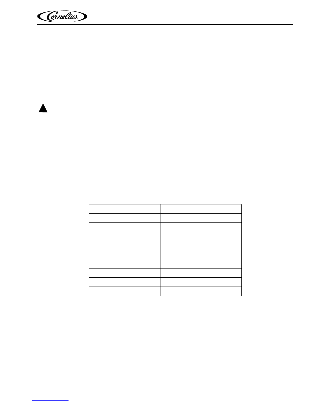
CRITICAL COMPONENT STORAGE TEMPERATURES
Component Storage Temperature Range
NUC -4°F – 158°F (-20°C – 70°C)
USB Hub -4°F – 185°F (-20°C – 85°C)
MFV PCBA -22°F – 176°F (-30°C – 80°C)
Agitator PCBA -22°F – 176°F (-30°C – 80°C)
LX3 PCBA -4°F – 158°F (-20°C – 70°C)
30 VDC Power Supply -40°F – 185°F (-40°C – 85°C)
12/24 VDC Power Supply -4°F – 185°F (-20°C – 85°C)
19 VDC Power Supply -4°F – 176°F (-20°C – 80°C)
ADA 32°F – 122°F (0°C – 50°C)
© 2015-2016, Cornelius Inc. - 3 - Publication Number: 620062609SER
PBD175 (Spire 3.0) Service Manual
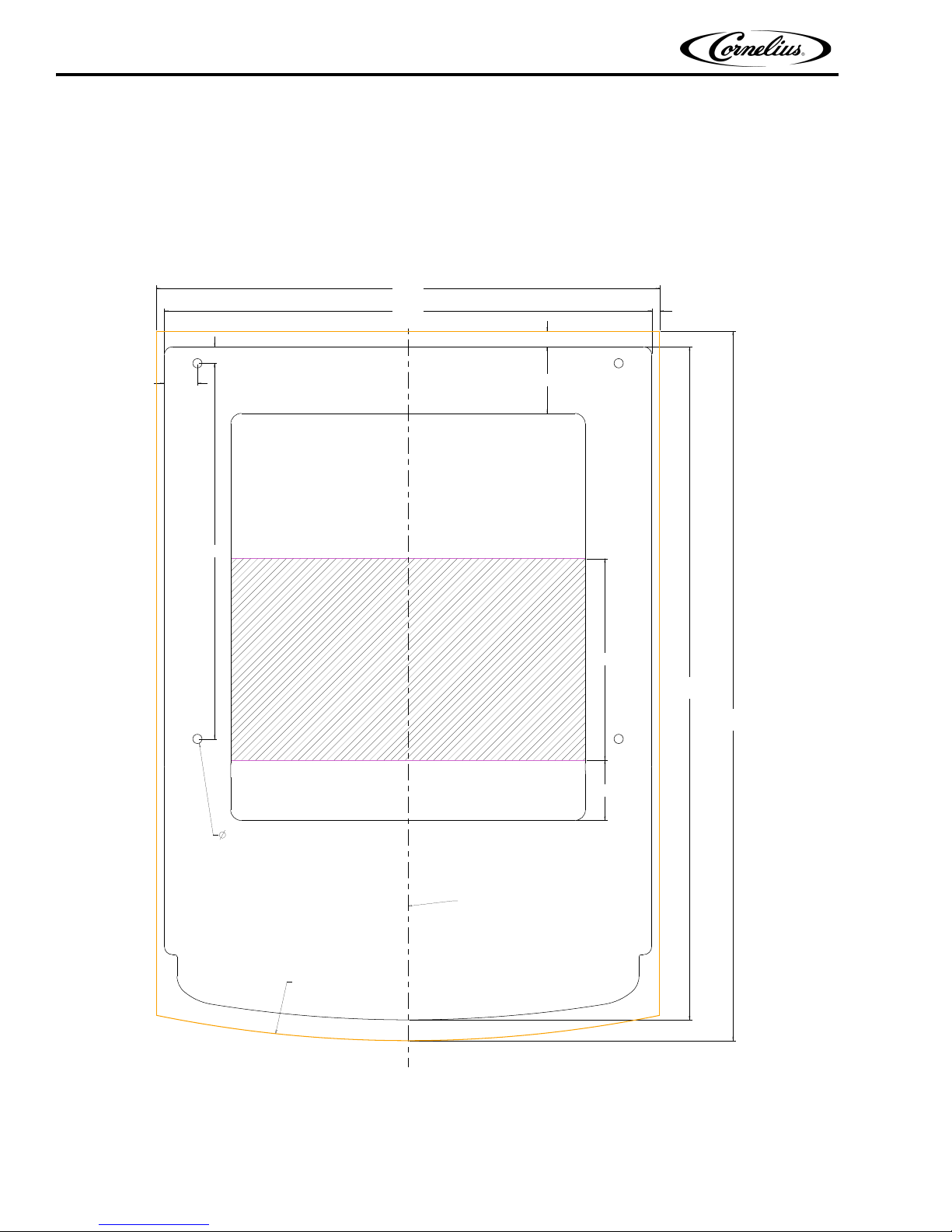
24.20
BASE PLATE
24.98
CLADDING
.82
1.64
3.00
3.30
.77
.39
35.21
CLADDING
33.41
BASE PLATE
18.64
10.000
CENTER LINE
CLADDING OUTLINE
1/2"
4 OUTER MOUNTING HOLES
PREFERRED CUTOUT
7" X 17.60"
NOTES:
-ALL DIMENSIONS ARE IN INCHES
-ALLOW FOR OPEN DOOR CLEARANCE
OF 5.5" TO THE LEFT OF THE UNIT
DATED: 8/6/2015
PREPARING THE COUNTER
In order to place the PBD175 (Spire 3.0) unit on a counter, the counter must be prepared by cutting an opening in the
counter to accommodate the syrup lines and power cord connection to the unit.
Marking and Cutting the Counter
To mark and cut the counter, refer to Figure 1.
Figure 1.
Publication Number: 620062609SER - 4 - ©2015-2016, Cornelius Inc.
PBD175 (Spire 3.0)) Service Manual
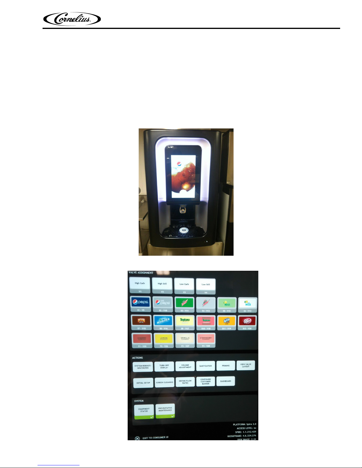
CONTROL PANEL
A microprocessor based control system monitors and controls all of the major systems and components of the unit.
This control system uses the front panel display to interface with the system, as shown in Figure 2.
The display is used by the operator to dispense drinks and by service technicians to access other screens for modifying operating characteristics or troubleshooting of the unit.
In addition to controlling the unit, the control system keeps track of the diagnostic information for use when adjusting
and/or repairing the unit. It also communicates with the local network through the SEN Modem.
The control system allows the service technician to perform service, maintenance and repair functions on the unit. This
is accomplished through the front panel display. The service screen with the basic service and maintenance functions is
shown in Figure 3.
.
Figure 2.
© 2015-2016, Cornelius Inc. - 5 - Publication Number: 620062609SER
Figure 3.
PBD175 (Spire 3.0) Service Manual
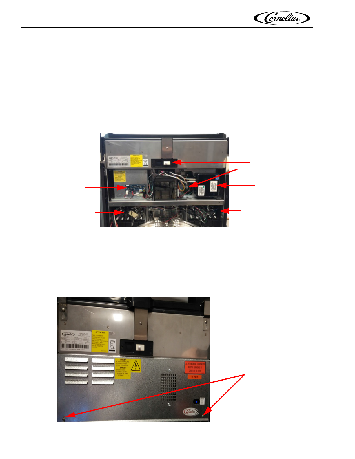
Valve control Board
Computer
Valve Assemblies
Valve Assemblies
Door Switch
LX3 Board
Mounting Screws
SPIRE SUBSYSTEMS
The subsystems that make up the PBD175 (Spire 3.0) unit are shown in Figure 4:
• Computer
• Top Power Supply is 30V only
• Bottom Power Supply is a 12V/24V
• Valve Control Board (MFV)
• ADA (Americans with Disabilities Act) Console
• LX3 Board
• Powered USB Hub (located beneath the computer)
• Valve Assemblies
Figure 4.
Computer
The computer controls all functions of the PBD175 (Spire 3.0) unit. This includes the display, all dispense functions,
setup and all external devices, such as the SEN modem.
The computer is shown in Figure 4. It has a power button and a LED on the front.
The computer is located in the top portion of the unit, behind the E-box cover shown in Figure 5.
Figure 5.
Publication Number: 620062609SER - 6 - ©2015-2016, Cornelius Inc.
PBD175 (Spire 3.0)) Service Manual
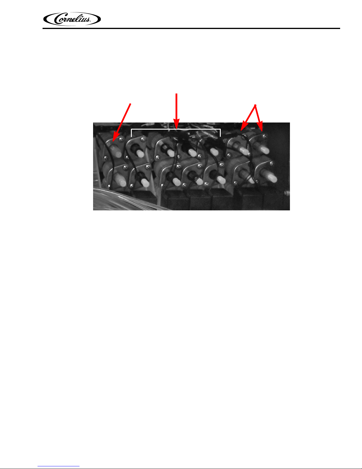
Water Valves
Syrup Valves
Flavor Shot Valves
Valve Assemblies
The valves are located behind the display panel and control the flow of the syrup, water and flavor shots to the valve
assembly.Image only applies to 16+8 unit.It also allows technicians to BRIX the unit. The valve assemblies are
shown in Figure 6. The white valves are water valves, the black valves are syrup valves and the purple valves are the
flavor shots.
Figure 6.
© 2015-2016, Cornelius Inc. - 7 - Publication Number: 620062609SER
PBD175 (Spire 3.0) Service Manual
Mounting
Nut
Mounting
Nut
Mounting Tabs
Mounting Tabs
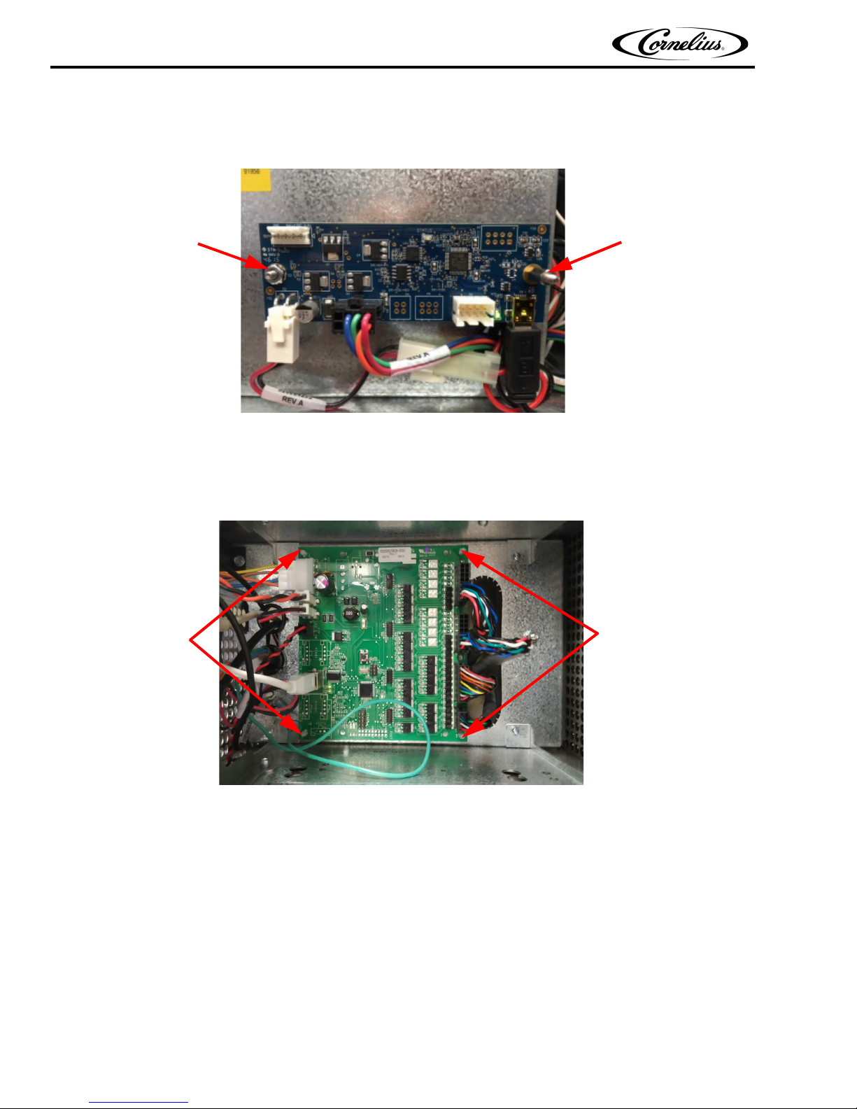
LX3 Board
The LX3 board is located on the upper-left of the unit, as shown in Figure 7. It is mounted to the unit by two mounting nuts, shown in Figure 7. It receives both 12 and 24 V input voltage.
Figure 7.
Valve Control Board
The Valve Control board is located on the upper-right of the unit, as shown in Figure 8. It is mounted to the unit by
four mounting tabs, shown in Figure 8.It contains both 12 and 30 V power.
Publication Number: 620062609SER - 8 - ©2015-2016, Cornelius Inc.
Figure 8.
PBD175 (Spire 3.0)) Service Manual
DispenseRightLeft Select
ADA Activation Button
Mounting
Tabs
Mounting
Tabs
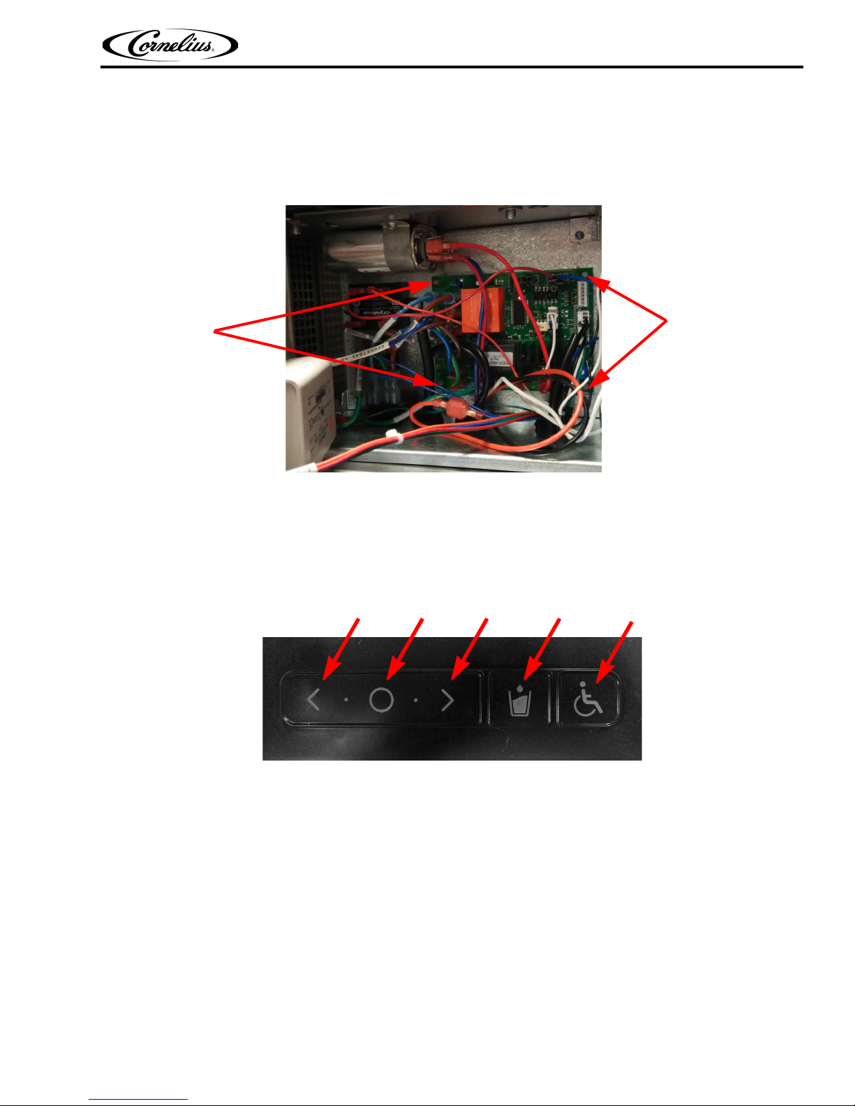
Agitator/Carbonator Control Board
The Agitator/Carbonator Control Board is located behind the 30 VDC and 12/24VDC power supplies. It supplies
function to the agitator motor, carb pump motor, off-cycle agitation settings, agitator motor heater, ice dispense
switch and safety switches. It receives both 24V and 115V input voltage.
Figure 9.
ADA Console
The ADA console controls the display screen and acts like a mouse to navigate the front panel display menu. The
ADA console sends its output to the computer through a USB interface. It is located at the bottom, right side of unit
front, as shown Figure 10.
Figure 10.
© 2015-2016, Cornelius Inc. - 9 - Publication Number: 620062609SER
PBD175 (Spire 3.0) Service Manual
Door Switch
CAUTION:
!
OPERATION
STARTING THE UNIT
To start the unit, plug the power cord into the appropriate, protected wall outlet. Open the front panel display by
grasping it on the right side and to open the unit’s door by grasping the grab handle. Machine (dispenser door) is
configurable as RH or LH hinge.By pressing the door switch, the front panel display will illuminate and display the
user screen, shown in Figure 2 on page 5.If the unit does not power up when plugged in, press the NUC power button
to turn it ON.
If the supply cord is damaged, it must be replaced by a cord available from Cornelius Inc.
Figure 11.
ICEMAKER CAPABILITY
The PBD175 (Spire 3.0) has a built-in icemaker adapter to accept a maximum 30” wide X 24” deep icemaker footprint. The dispenser is supplied and shipped with needed parts for this icemaker installation. Any ice maker smaller
than these dimensions may require an additional kit for proper icemaker installation. Contact your Cornelius Sale
Representative for additional information.
NOTE: Icemaker needs to be equipped with a low level ice sensor (bin stat) to prevent hopper overfill-
ing or icemaker harvest issues. Failure to install this sensor may result in equipment damage or
ice dispensing issues.
Publication Number: 620062609SER - 10 - ©2015-2016, Cornelius Inc.
PBD175 (Spire 3.0)) Service Manual
!
WARNING:
CAUTION:
!
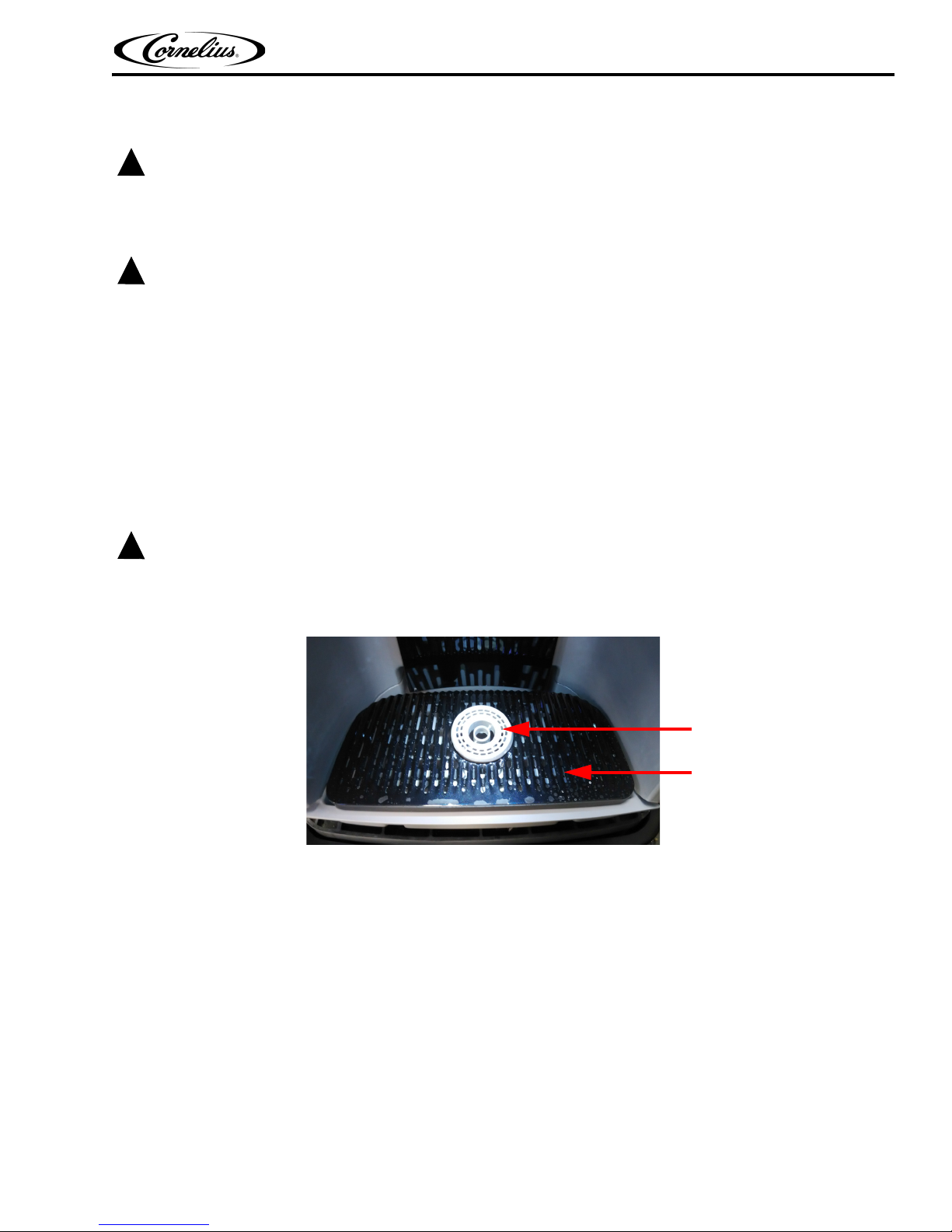
Ice Slide
Cup pedestal
!
WARNING:
PREVENTATIVE MAINTENANCE
Shutdown unit via the proper software shutdown procedure. When the computer has fully turned off, unplug the unit
from the wall outlet.
Failure to comply could result in serious injury, death or damage to the equipment.
Do not use metal scrapers, sharp objects or abrasives on the ice storage hopper, top cover or exterior surfaces, as
damage to the unit may result. Do not use solvents or other cleaning agents as they may attack the material
resulting in damage to the unit.
• Soap solution – Use a mixture of mild detergent and warm (100° F) potable water.
• Sanitizing Solution – Dissolve 1 packet [1 oz. (29.6 ml)] of Stera Sheen Green Label (or KAY-5 Sanitizer/
Cleaner) into 2-1/2 gallons (3.79 l) of warm [80-100° F (26.7-37.8° C)] potable water to ensure 100 ppm of
chlorine.
CLEANING THE PBD175 (SPIRE 3.0)
Daily Cleaning
Do not use abrasive cleansers.
Remove the cup pedestal from the ice slide, as shown in Figure 12, and clean them with warm soapy water, rinse
them with clean water and allow them to air dry.
Figure 12.
Wipe down the display screen and the exterior of the unit with warm soapy water. Then rinse with clean water and
wipe with a clean soft cloth.
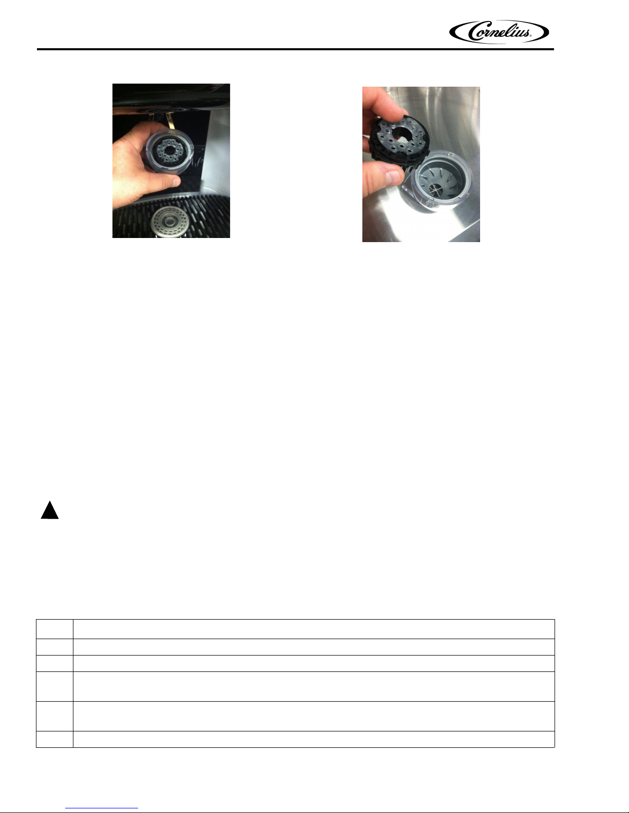
Remove the nozzle and separate it components, as shown in Figure 13 and Figure 14. Wash them in warm soapy
water, rinse in clean warm water and allow to air dry.
Wipe down the bottom of the dispensing valve with a clean damp cloth.
© 2015-2016, Cornelius Inc. - 11 - Publication Number: 620062609SER
PBD175 (Spire 3.0) Service Manual
!
WARNING:
Figure 13.
Spray the nozzle and diffuser inside and outside with approved sanitizing solution, reinstall the diffuser and nozzle on
the valve and allow them to air dry.
Pour warm, soapy water down the drains to keep them clean and flowing properly and reinstall the cup rest into the
drip tray.
Figure 14.
Daily Maintenance
1 Check the temperature, smell and taste of the product.
2 Check ice in the bin.
3 Check the water pressure coming to the unit monitoring the pressure gauges on the back room package.
4 Check the carbonation of the drinks.
5 Check the level of the CO
6 Check the date on all of the BIBs.
2 supply to the system.
MONTHLY CLEANING
NOTE: Perform all the daily procedures in addition to the monthly cleaning procedures.
Only trained and certified electrical, plumbing and refrigeration technicians should service this unit.
All wiring and plumbing must conform to national and local codes. Failure to comply could
result in serious injury, death or equipment damage.
Sanitizing Syrup Lines and the BIB System
Step Action
1
Remove all the quick disconnects from all the BIB containers.
2
Fill a suitable pail with soap solution.
3
Submerge all disconnects into the soap solution and then clean them using a nylon bristle brush. (Do not
use a wire brush). Rinse them with clean water.
4
Using the same soap solution, perform Steps 7 through 11. It is not necessary to allow the soap solution to
remain in the lines for 15 minutes.
5
Rinse all components using clean water.
Publication Number: 620062609SER - 12 - ©2015-2016, Cornelius Inc.
Table 1.
PBD175 (Spire 3.0)) Service Manual
Table 1.
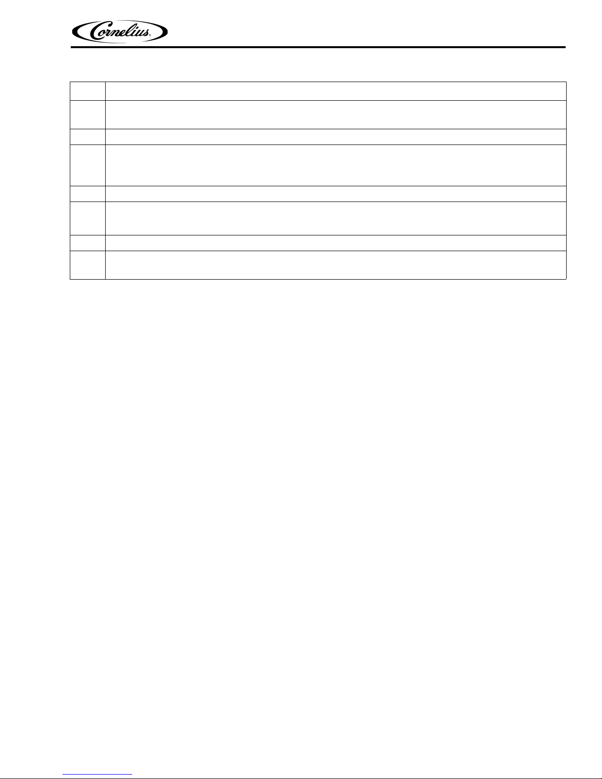
Step Action
6
Empty the plastic pail and prepare approximately five gallons of sanitizing solution. See sanitizing solution
instructions on page 11.
7
Submerge the BIB disconnects in the sanitizing solution.
8
Sanitizing fittings must be attached to each BIB disconnect. If these fittings are not available, the fittings
from empty BIB bags can be cut from the bags and used. These fittings open the disconnect so the sanitizing solution can be drawn through the disconnect.
9
Place all the BIB disconnects into the pail of sanitizing solution.
10
Select and press the syrup or water icon to be cleaned. Refer to Table 2 on page 14.
NOTE: Water will also be dispensed in this mode when dispensing any brand or flavor.
11
Enter the priming mode to prime up to five valves at a time.
12
Remove the nozzle components, clean in a soap solution, rinse and replace. Refer to Figure 13 and Figure
14.
© 2015-2016, Cornelius Inc. - 13 - Publication Number: 620062609SER
PBD175 (Spire 3.0) Service Manual
Start at the bottom and around
the P
ENTERING SERVICE MODE
Service Screen
The unit contains a service mode that is accessed through the front panel display. This allows service personnel to set up the
unit or service it.
To shut down the computer through the service screen, perform the procedure in Table 2.
Table 2.
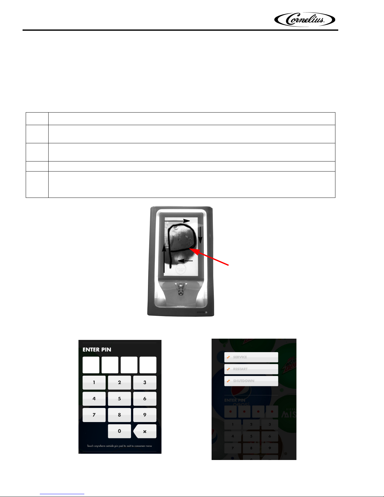
Step Action
1
Enter the service menu by using your finger to draw two large “P”s on the front panel display (Figure 15),
one right after the other. Do not lift your finger while drawing the letter “P”.
2
After the two “P”s have been accepted, the PIN number screen is displayed, as shown in Figure 16 .
Enter the correct PIN number.
3
When the PIN number is entered, the next screen shown in Figure 16 is displayed.
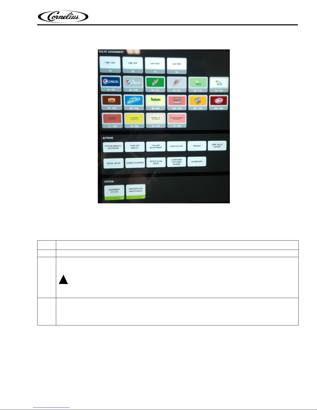
4
When the Service button is pressed in Figure 17, the screen shown in Figure 18 is displayed. This displays the service menus allowing the technician to map valves, prime valves and shutdown the computer, as well as other service related functions.
Figure 16.
Publication Number: 620062609SER - 14 - ©2015-2016, Cornelius Inc.
Figure 15.
Figure 17.
PBD175 (Spire 3.0)) Service Manual
!
WARNING:
Figure 18.
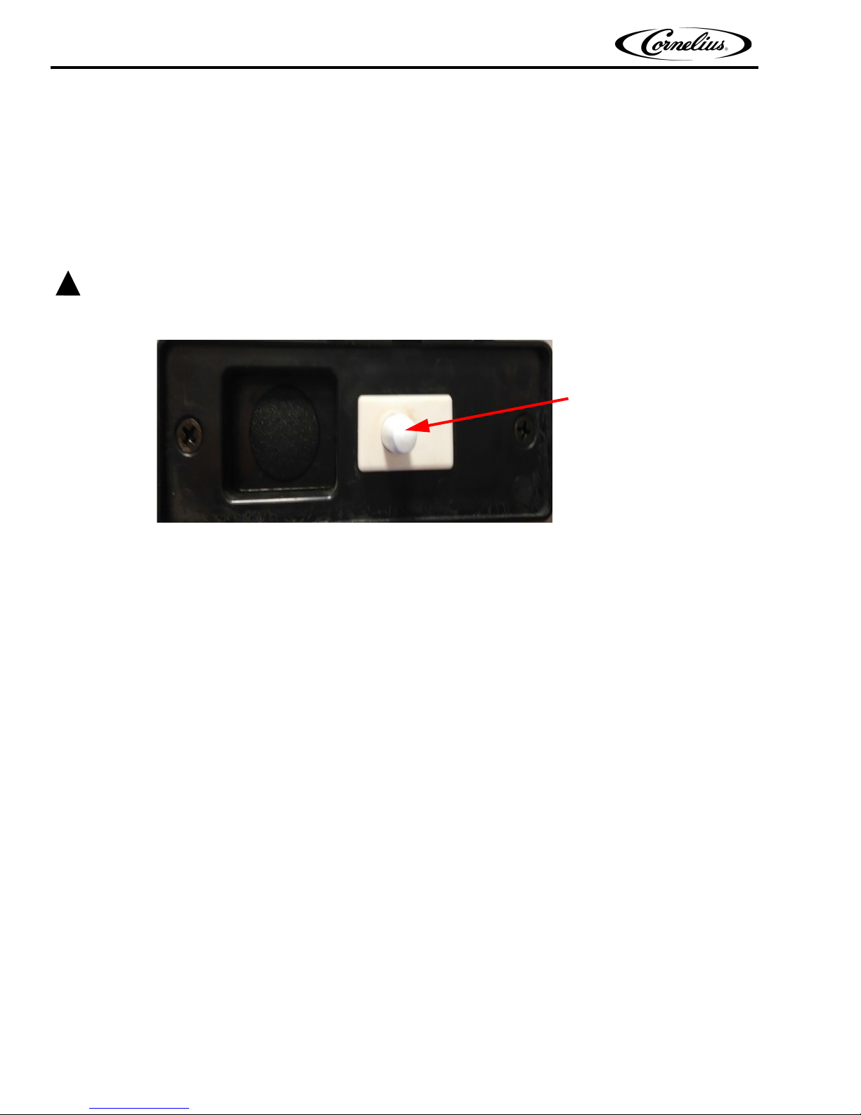
NUC Power Button
To shut down the computer using the computer power button, perform the procedure in Table 3.
Table 3.
Step Action
1
Open the unit door.
2
To shut down the computer, press and release the exposed NUC power button, as shown in Figure 19. This
operation provides the same function as a software shutdown.
Holding the NUC power button for 5 seconds is an unsafe, hard shutdown. This is not advised during normal
operation
3
To reboot the computer, pres the NUC power button for 1 second. The blue light illuminates and the display
goes through the boot up routine. At the end of the routine, the main user screen is displayed. Wait 15 seconds after the main user screen is displayed for communications to be completed to the Valve Control
board.
.
© 2015-2016, Cornelius Inc. - 15 - Publication Number: 620062609SER
 Loading...