

IDC PRO 255
Installation Manual
Release Date: August 05, 2016
Publication Number: 621058578INS
Revision Date: June 20, 2018
Revision: B
Visit the Cornelius web site at
www.cornelius-usa.com for all your Literature needs.

The products, technical information, and instructions contained in this manual are subject to change without notice.
RECYCLE
These instructions are not intended to cover all details or variations of the equipment, nor to provide for every possible
contingency in the installation, operation or maintenance of this equipment. This manual assumes that the person(s)
working on the equipment have been trained and are skilled in working with electrical, plumbing, pneumatic, and
mechanical equipment. It is assumed that appropriate safety precautions are taken and that all local safety and con
struction requirements are being met, in addition to the information contained in this manual.
This Product is warranted only as provided in Cornelius’ Commercial Warranty applicable to this Product and is subject to all of the restrictions and limitations contained in the Commercial Warranty.
Cornelius will not be responsible for any repair, replacement or other service required by or loss or damage resulting
from any of the following occurrences, including but not limited to, (1) other than normal and proper use and normal
service conditions with respect to the Product, (2) improper voltage, (3) inadequate wiring, (4) abuse, (5) accident, (6)
alteration, (7) misuse, (8) neglect, (9) unauthorized repair or the failure to utilize suitably qualified and trained persons
to perform service and/or repair of the Product, (10) improper cleaning, (11) failure to follow installation, operating,
cleaning or maintenance instructions, (12) use of “non-authorized” parts (i.e., parts that are not 100% compatible with
the Product) which use voids the entire warranty, (13) Product parts in contact with water or the product dispensed
which are adversely impacted by changes in liquid scale or chemical composition.
Contact Information:
To inquire about current revisions of this and other documentation or for assistance with any Cornelius product contact:
www.cornelius.com
800-238-3600
Trademarks and Copyrights:
This document contains proprietary information and it may not be reproduced in any way without permission from
Cornelius.
-
This document contains the original instructions for the unit described.
CORNELIUS INC
101 Regency Drive
Glendale Heights, IL
Tel: + 1 800-238-3600
Printed in U.S.A.
Correct Disposal of this Product
This marking indicates that this product should not be disposed with other household wastes throughout the EU. To
prevent possible harm to the environment or human health from uncontrolled waste disposal, recycle it responsibly to
promote the sustainable reuse of material resources. To return your used device, please use the return and collection
systems or contact the retailer where the product was purchased. They can take this product for environmental safe
recycling.

TABLE OF CONTENTS
Safety Instructions. . . . . . . . . . . . . . . . . . . . . . . . . . . . . . . . . . . . . . . . . . . . . . . . . . . . . . . . . . . . . . . . . 1
Read and Follow ALL Safety Instructions . . . . . . . . . . . . . . . . . . . . . . . . . . . . . . . . . . . . . . . . . . . . . 1
Safety Overview . . . . . . . . . . . . . . . . . . . . . . . . . . . . . . . . . . . . . . . . . . . . . . . . . . . . . . . . . . . 1
Recognition . . . . . . . . . . . . . . . . . . . . . . . . . . . . . . . . . . . . . . . . . . . . . . . . . . . . . . . . . . . . . . 1
Different Types of Alerts. . . . . . . . . . . . . . . . . . . . . . . . . . . . . . . . . . . . . . . . . . . . . . . . . . . . . . . . 1
Safety Tips . . . . . . . . . . . . . . . . . . . . . . . . . . . . . . . . . . . . . . . . . . . . . . . . . . . . . . . . . . . . . . . . . . . . . 1
Qualified Service Personnel. . . . . . . . . . . . . . . . . . . . . . . . . . . . . . . . . . . . . . . . . . . . . . . . . . . . . . . . 2
Safety Precautions. . . . . . . . . . . . . . . . . . . . . . . . . . . . . . . . . . . . . . . . . . . . . . . . . . . . . . . . . . . . . . . 2
Shipping And Storage . . . . . . . . . . . . . . . . . . . . . . . . . . . . . . . . . . . . . . . . . . . . . . . . . . . . . . . . . . . . 2
CO2 (Carbon Dioxide) Warning . . . . . . . . . . . . . . . . . . . . . . . . . . . . . . . . . . . . . . . . . . . . . . . . . . . . . 2
Mounting in or on a Counter . . . . . . . . . . . . . . . . . . . . . . . . . . . . . . . . . . . . . . . . . . . . . . . . . . . . . . . 2
System Overview . . . . . . . . . . . . . . . . . . . . . . . . . . . . . . . . . . . . . . . . . . . . . . . . . . . . . . . . . . . . . . . . . . 4
Features. . . . . . . . . . . . . . . . . . . . . . . . . . . . . . . . . . . . . . . . . . . . . . . . . . . . . . . . . . . . . . . . . . . . . . . 4
Specifications. . . . . . . . . . . . . . . . . . . . . . . . . . . . . . . . . . . . . . . . . . . . . . . . . . . . . . . . . . . . . . . . . . . 4
Installation . . . . . . . . . . . . . . . . . . . . . . . . . . . . . . . . . . . . . . . . . . . . . . . . . . . . . . . . . . . . . . . . . . . . . . . 6
Unit Location . . . . . . . . . . . . . . . . . . . . . . . . . . . . . . . . . . . . . . . . . . . . . . . . . . . . . . . . . . . . . . . . . . . 6
Direct Counter Installation . . . . . . . . . . . . . . . . . . . . . . . . . . . . . . . . . . . . . . . . . . . . . . . . . . . . . . . . . 6
Adjusting the Carbonator CO2 Regulator and Turning on the Water Inlet Supply Line . . . . . . . . . . . 8
Gate Restrictor Plate Adjustment. . . . . . . . . . . . . . . . . . . . . . . . . . . . . . . . . . . . . . . . . . . . . . . . . . . . 8
Connecting Product to the Unit . . . . . . . . . . . . . . . . . . . . . . . . . . . . . . . . . . . . . . . . . . . . . . . . . . . . . 9
Water & Syrup Line Connections. . . . . . . . . . . . . . . . . . . . . . . . . . . . . . . . . . . . . . . . . . . . . . . . . . . . 9
Product Line Connections . . . . . . . . . . . . . . . . . . . . . . . . . . . . . . . . . . . . . . . . . . . . . . . . . . . . . . 9
Unit Operation . . . . . . . . . . . . . . . . . . . . . . . . . . . . . . . . . . . . . . . . . . . . . . . . . . . . . . . . . . . . . . . . . 10
Preparing for Operation . . . . . . . . . . . . . . . . . . . . . . . . . . . . . . . . . . . . . . . . . . . . . . . . . . . . . . . . . . . 11
Service Mode . . . . . . . . . . . . . . . . . . . . . . . . . . . . . . . . . . . . . . . . . . . . . . . . . . . . . . . . . . . . . . . . . . 11
Initial Setup . . . . . . . . . . . . . . . . . . . . . . . . . . . . . . . . . . . . . . . . . . . . . . . . . . . . . . . . . . . . . . . . . . . 13
Adding Syrup . . . . . . . . . . . . . . . . . . . . . . . . . . . . . . . . . . . . . . . . . . . . . . . . . . . . . . . . . . . . . . . 13
Mapping Brands . . . . . . . . . . . . . . . . . . . . . . . . . . . . . . . . . . . . . . . . . . . . . . . . . . . . . . . . . . . . . 17
Purging The Syrup Lines . . . . . . . . . . . . . . . . . . . . . . . . . . . . . . . . . . . . . . . . . . . . . . . . . . . . . . 19
Syrup Line Cleaning & Sanitizing. . . . . . . . . . . . . . . . . . . . . . . . . . . . . . . . . . . . . . . . . . . . . . . . 21
Adjusting the Water to Syrup Ratio (BRIX) . . . . . . . . . . . . . . . . . . . . . . . . . . . . . . . . . . . . . . . . 22
Cleaning Interior Surfaces . . . . . . . . . . . . . . . . . . . . . . . . . . . . . . . . . . . . . . . . . . . . . . . . . . . . . 24
Unit Shutdown/Restart . . . . . . . . . . . . . . . . . . . . . . . . . . . . . . . . . . . . . . . . . . . . . . . . . . . . . . . . . . . 27
Editing the Media Playlist. . . . . . . . . . . . . . . . . . . . . . . . . . . . . . . . . . . . . . . . . . . . . . . . . . . . . . . . . 28
Updating Software Revisions. . . . . . . . . . . . . . . . . . . . . . . . . . . . . . . . . . . . . . . . . . . . . . . . . . . . . . 31
Plumbing Diagram . . . . . . . . . . . . . . . . . . . . . . . . . . . . . . . . . . . . . . . . . . . . . . . . . . . . . . . . . . . . . . 33
Wiring Diagram . . . . . . . . . . . . . . . . . . . . . . . . . . . . . . . . . . . . . . . . . . . . . . . . . . . . . . . . . . . . . . . . 34
Troubleshooting. . . . . . . . . . . . . . . . . . . . . . . . . . . . . . . . . . . . . . . . . . . . . . . . . . . . . . . . . . . . . . . . . . 36
Unit Troubleshooting . . . . . . . . . . . . . . . . . . . . . . . . . . . . . . . . . . . . . . . . . . . . . . . . . . . . . . . . . . . . 36
Carbonator Troubleshooting . . . . . . . . . . . . . . . . . . . . . . . . . . . . . . . . . . . . . . . . . . . . . . . . . . . . . . 37
SAFETY INSTRUCTIONS
!
DANGER:
!
WARNING:
CAUTION:
!
!
READ AND FOLLOW ALL SAFETY INSTRUCTIONS
Safety Overview
• Read and follow ALL SAFETY INSTRUCTIONS in this manual and any warning/caution labels on the unit
(decals, labels or laminated cards).
• Read and understand ALL applicable OSHA (Occupational Safety and Health Administration) safety regulations and/or national and local codes before operating this unit.
Recognition
Recognize Safety Alerts
This is the safety alert symbol. When you see it in this manual or on the unit, be alert to
the potential of personal injury or damage to the unit.
Different Types of Alerts
IDC Pro 255 Installation Manual
Indicates an immediate hazardous situation which, if not avoided, WILL result in serious injury, death or equipment
damage.
Indicates a potentially hazardous situation which, if not avoided, COULD result in serious injury, death, or equipment
damage.
Indicates a potentially hazardous situation which, if not avoided, MAY result in minor or moderate injury or equipment
damage.
SAFETY TIPS
• Carefully read and follow all safety messages in this manual and safety signs on the unit.
• Keep safety signs in good condition and replace missing or damaged items.
• Learn how to operate the unit and how to use the controls properly.
• Do not let anyone operate the unit without proper training. This appliance is not intended for use by very
young children or infirm persons without supervision. Young children should be supervised to ensure that
they do not play with the appliance.
• Keep your unit in proper working condition and do not allow unauthorized modifications to the unit.
NOTE: The dispenser is not designed for a wash-down environment and MUST NOT be placed in an area
where a water jet could be used.
© 2016-2018, Cornelius Inc. - 1 - Publication Number: 621058578INS

IDC Pro 255 Installation Manual
!
WARNING:
!
WARNING:
CAUTION:
!
CAUTION:
!
!
DANGER:
!
WARNING:
QUALIFIED SERVICE PERSONNEL
Only trained and certified electrical, plumbing and refrigeration technicians should service this unit. ALL WIRING
AND PLUMBING MUST CONFORM TO NATIONAL AND LOCAL CODES. FAILURE TO COMPLY COULD
RESULT IN SERIOUS INJURY, DEATH OR EQUIPMENT DAMAGE.
IF THE SUPPLY CORD IS DAMAGED, IT MUST BE REPLACED BY THE MANUFACTURER, ITS SERVICE
AGENT OR SIMILARLY QUALIFIED PERSONS IN ORDER TO AVOID A HAZARD.
SAFETY PRECAUTIONS
This unit has been specifically designed to provide protection against personal injury. To ensure continued protection,
observe the following:
Disconnect power to the unit before servicing following all lock out/tag out procedures established by the user. Verify
all of the power is off to the unit before any work is performed.
Failure to disconnect the power could result in serious injury, death or equipment damage.
Always be sure to keep area around the unit clean and free of clutter. Failure to keep this area clean may result in
injury or equipment damage.
SHIPPING AND STORAGE
Before shipping, storing, or relocating the unit, the unit must be sanitized and all sanitizing solution must be drained
from the system. A freezing ambient environment will cause residual sanitizing solution or water remaining inside the
unit to freeze resulting in damage to internal components.
CO2 (CARBON DIOXIDE) WARNING
CO2 displaces oxygen. Strict attention MUST be observed in the prevention of CO2 gas leaks in the entire CO2 and
soft drink system. If a CO
contaminated area before attempting to repair the leak. Personnel exposed to high concentrations of CO
experience tremors which are followed rapidly by loss of consciousness and DEATH.
2 gas leak is suspected, particularly in a small area, IMMEDIATELY ventilate the
2 gas
MOUNTING IN OR ON A COUNTER
When installing the unit in or on a counter top, the counter must be able to support a weight in excess of 1,000 lbs.
(454 kg.) to insure adequate support for the unit. Failure to comply could result in serious injury, death or damage to
the equipment.
NOTE: Many units incorporate the use of additional equipment such as ice makers. When any addition
equipment is used you must check with the equipment manufacturer to determine the additional
weight the counter will need to support to ensure a safe installation.
Publication Number: 621058578INS - 2 - © 2016-2018, Cornelius Inc.

IDC Pro 255 Installation Manual
NOISE LEVEL
This unit emits acoustical noise with an A-weighted sound pressure level no greater than 75dB, as measured in
accordance with ED 60335-2-75.
© 2016-2018, Cornelius Inc. - 3 - Publication Number: 621058578INS

IDC Pro 255 Installation Manual
CAUTION:
!
SYSTEM OVERVIEW
The IDC PRO 255 unit solves your ice and beverage service needs in a sanitary, space saving, economical way. It is
designed to be manually filled with ice from any remote ice making source. The unit distributes cubes (up to 1-1/4 inch
in size), Cubelet and compressed (not flaked) ice. Also, the unit includes beverage valves, a cold plate, an internal
carbonator tank and an external pump for the carbonator.
The unit cannot be used with crushed or flaked ice. Use of bagged ice which has frozen into large chunks can void
warranty. The unit agitator is not designed to be an ice crusher. Use of large chunks of ice which “jam up” inside the
hopper will cause failure of the agitator motor and damage to the hopper. If bagged ice is used, it must be carefully
and completely broken into small, cube-sized pieces and left to “temper” or warm up for a minimum of 20 minutes in
room temperature before loading into the unit hopper.
FEATURES
• Brand density - 10 brands on each side, 7 chilled, 3 ambient and up to 8 flavor shots (4 per side) for over
320 drink combinations.
• Large HD promotional display
• 255 lb. capacity ice cube hopper
• Internal cold carbonation with remote pump
• Total carb/mid-carb flexibility on each brand
• Dispenses cubed or chewable soft ice
• UI Touch screen.
SPECIFICATIONS
Model IDC Pro 255
Maximum Number of Valves available 36 Total; 20 brands, 8 flavors, 4 Pain & 4 Carb
Built-in Cold Plate Yes
Voltage
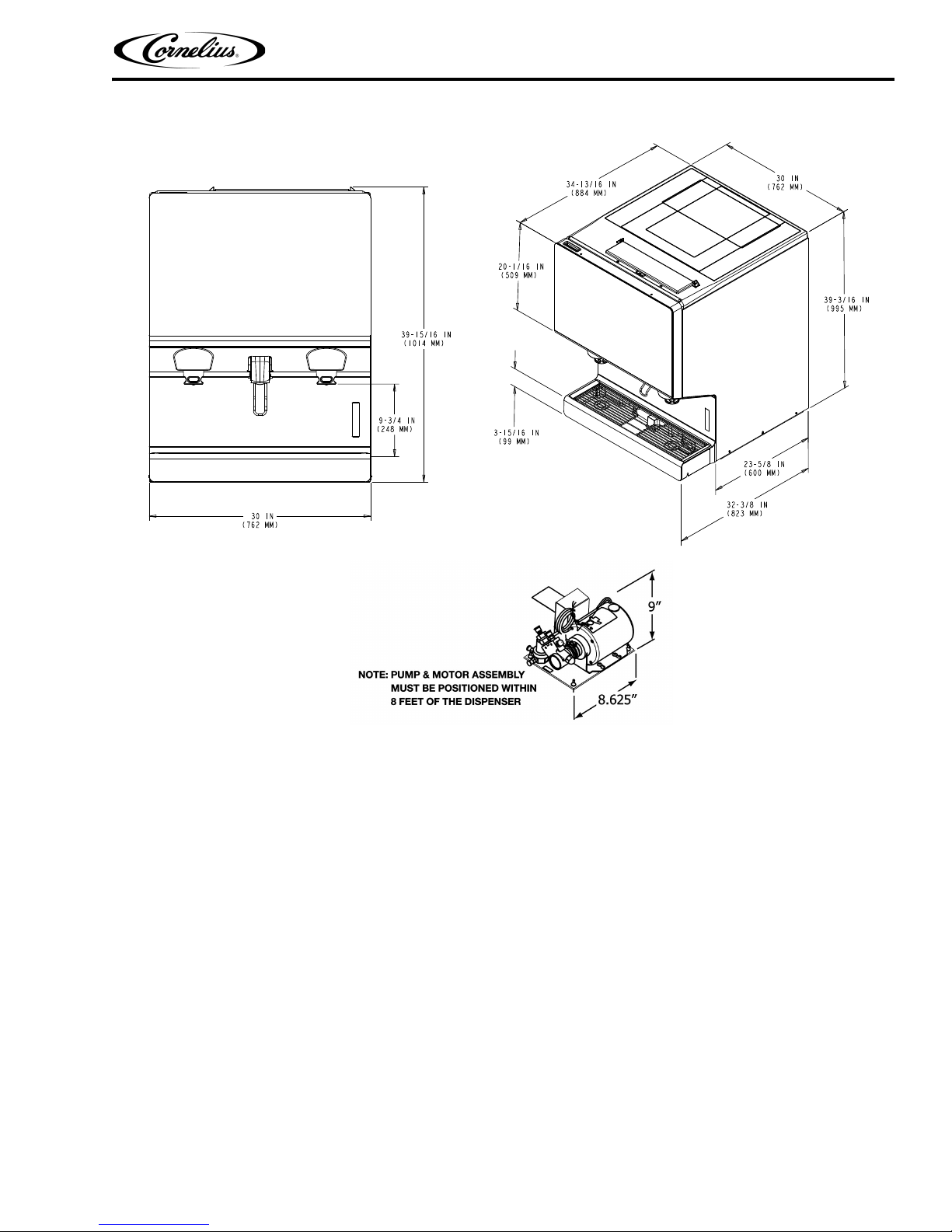
Height 39-3/16 in. (.955 m) to top of Adapter lid
Depth 32-3/8 in. (0.823 m)
Width 30 in. (0.762 m)
Screen Dimensions 32 in. Diagonally
2 Operating Pressure
CO
Water Pressure 50-60 psi (345-414 Kpa) at pump
Water Volume Minimum flow rate, 125 gal/hr. (0.473 cubic meters/hr.)
Shipping Weight 545 lb. (247.2 kg)
Counter Weight 440 lb. (199.6 kg)
Ice Storage Weight 255 lbs. (115.7 kg)
Cup Clearance 9-3/4 in. (24.77 cm)
Ambient Operating Temperature 65 to 95° F (18.3 to 35° C)
Table 1.
120 V 60 Hz, single phase; 8.5A. of total unit draw
220 -240V 50 - 60Hz, single phase; 5.5A of total unit draw
More than 80 psig (5.52 bar) feeding carbonator pump (75
psig (5.17 bar) fixed regulator on pump deck)
Publication Number: 621058578INS - 4 - © 2016-2018, Cornelius Inc.
IDC Pro 255 Installation Manual
Figure 1.
© 2016-2018, Cornelius Inc. - 5 - Publication Number: 621058578INS
IDC Pro 255 Installation Manual
!
WARNING:
!
WARNING:
INSTALLATION
Only trained and certified electrical, plumbing and refrigeration technicians should service this unit.
ALL WIRING AND PLUMBING MUST CONFORM TO NATIONAL AND LOCAL CODES. FAILURE TO COMPLY
COULD RESULT IN SERIOUS INJURY, DEATH OR EQUIPMENT DAMAGE.
This equipment must be installed to comply with the International Plumbing Code of the International Code Council
and the Food Code Manual 01 the Food and Drug Administration (FDA). For models installed outside the U.S.A., you
must comply with the applicable Plumbing/Sanitation Code for your area.
Failure to comply could result in serious injury, death or damage to the equipment.
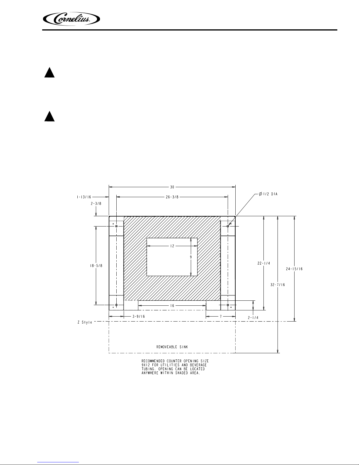
UNIT LOCATION
The unit must be sealed to the counter or placed on the included 4” legs (drip tray style unit only). The template
drawing indicates where openings can be cut in the counter. Locate the desired position for the unit, then mark the
outline dimensions on the counter using the template drawing, shown in Figure 2.. Cut the necessary openings in the
counter.
DIRECT COUNTER INSTALLATION
To install the unit on a counter, perform the procedure in Table 2.
Table 2.
Step Action
1 Locate the unit indoors on a level counter top.
When the unit is mounted directly on the counter top, the b
cord are routed through the large opening in the bottom of the unit. See the mounting template
shown in Figure 2. for locating the required clearance openings in the counter.
2
NOTE: Recommended counter opening size 9X12 for utilities and beverage tub-
ing. Opening can be located anywhere within the shaded area.
Apply a continuous bead of NSF International (NSF) silastic sealant (Dow 732 or equal) approximately 1/4-inch inside of the unit outline dimensions and around all openings. Then, position the
3
unit on the counter within the outline dimensions. All excess sealant must be wiped away
immediately.
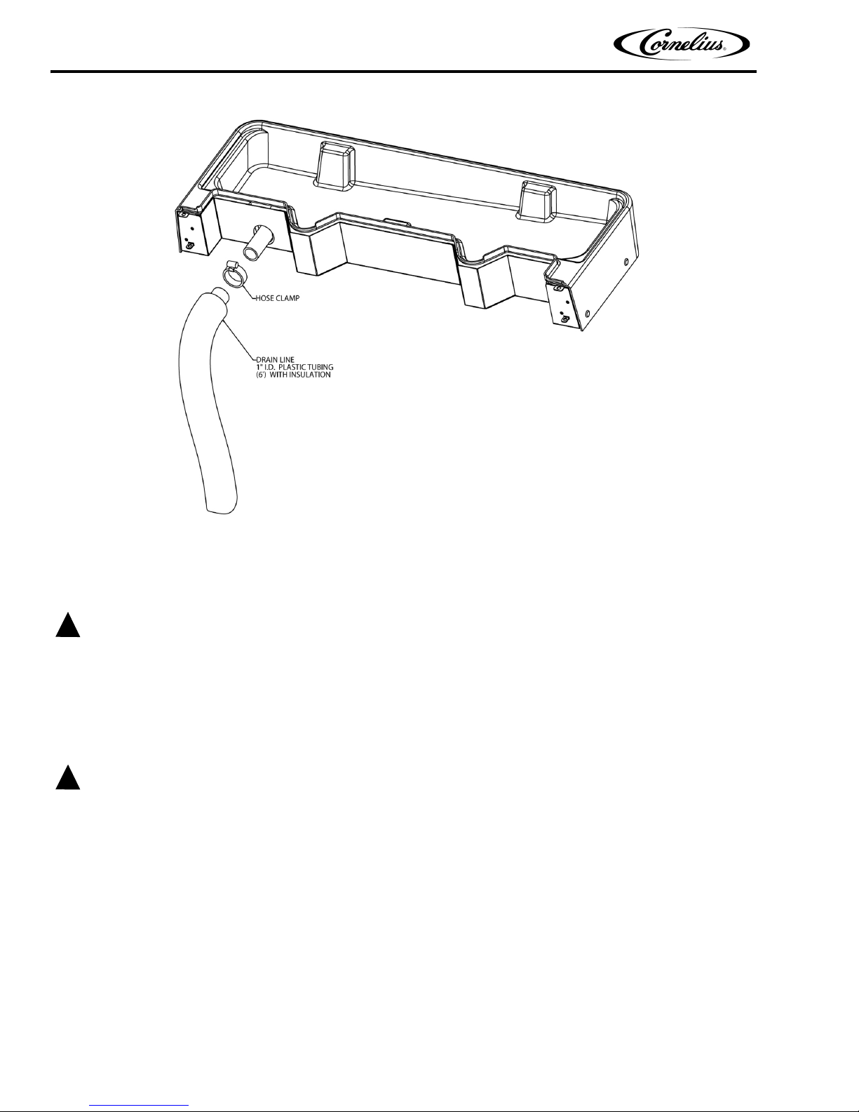
4 Install the drain tube on to the drip tray, as shown in Figure 3..
Route the drain tube to an open drain with the end of the tube above the “flood” level of the drain.
se the tubing, fittings, clamps, and insulation provided with the unit to assemble the drain. The
U
5
completed drain line must pitch continuously downward and contain no “traps” or improper drainage results.
Locate the carbonator pump assembly and connect the po
The cord is connected to the unit’s electrical box and has an electrical connector on the end that plugs
into a receptacle in the junction box at the carbonator pump assembly. Connect inlet water to the
6
pump and the pump outlet to the unit using 3/8-inch food-grade tubing. Disable the pump from operating by switching the switch in the carbonator pump assembly junction box to the OFF position.
Connect the beverage system product
7
NOTE: See the Plumbing Diagram (Figure 9.) or the decal on the lower front of
the unit for the location of syrup and water connections.
8 Clean the hopper interior (see “Cleaning Interior Surfaces” section on page 24).
Connect the unit power cord to a 120 volt, 60 cycl
Volt units, a 3-wire power cord is provided. An appropriate power cord for the particular country
9
may need to be provided by the installer.
tubes as indicated in the Plumbing Diagram, Figure 9..
everage tubes, drain tube and power
wer cord from the dispenser to the pump.
e, 3-wire grounded receptacle. For 220-240
Publication Number: 621058578INS - 6 - © 2016-2018, Cornelius Inc.
IDC Pro 255 Installation Manual
CAUTION:
!
CAUTION:
!
NOTE: Cornelius Inc. recommends that a water shutoff valve and water filter be installed in the plain water
inlet supply line. A Cornelius Water Filter (P/N 313860000) and Quick Disconnect Set (P/N
313867000) are recommended.
Check the minimum flow rate and the maximum pressure of the plain water inlet supply line. MINIMUM FLOW RATE
MUST BE AT LEAST 125-GALLONS PER HOUR. If flow rate is less than 125-gallons per hour, starving of the car
bonator water pump can occur. Starving causes the carbonator
stat on the pump outlet to stop the water pump motor.
INCOMING PLAIN WATER INLET SUPPLY LINE WATER TO PUMP PRESSURE MUST REMAIN A MINIMUM OF
10 psi BELOW THE CARBONATED CO2 OPERATING PRESSURE. (Example: Carbonator CO
sure is 75 psi and the maximum water pressure can be no more t
2 operating pressure) can cause carbonator flooding, malfunction, and leakage through the carbonator relief valve.
CO
If water is exceeding maximum pressure specifications, a Water Pressure Regulator Kit must be installed in the plain
water inlet supply line. If a fitting connector is not available, tap into the plain water supply line with a 3/8 flare saddle
valve.
water pump to overheat, causing the safety thermo-
2 operating pres-
han 65 psi, etc.). Water over pressure (higher than
-
© 2016-2018, Cornelius Inc. - 7 - Publication Number: 621058578INS
Figure 2.
IDC Pro 255 Installation Manual
CAUTION:
!
CAUTION:
!
Figure 3.
ADJUSTING THE CARBONATOR CO2 REGULATOR AND TURNING ON THE WATER
NLET SUPPLY LINE
I
Before connecting the CO2 regulator assembly to a CO2 cylinder, turn the regulator adjusting screw to the left (counterclockwise) until all tension is relieved
1. Open (counterclockwise) the CO
the valve fully to back-seat it. (Back-seating the valve on the CO
shaft).
2. The source CO
Never operate the carbonator pump with the water inlet supply line shutoff valve closed. “Dry running” the water pump
will burn out the pump. A pump damaged in this manner is not covered by the warranty.
3. Open the water inlet supply line shutoff valve.
4. Exercise one of the dispensing valves to exhaust trapped air inside the carbonator tank.
2 regulator must be adjusted to a minimum setting of 80 psi.
from the adjusting screw spring.
2 bulk cylinder valve slightly to allow the lines to slowly fill with gas, then open
2 bulk tank prevents leakage around the valve
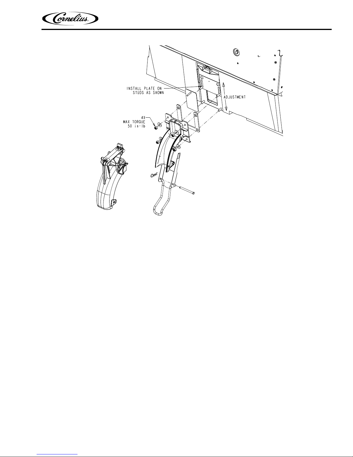
GATE RESTRICTOR PLATE ADJUSTMENT
The rate at which ice is dispensed is adjusted by adjusting the opening of the gate Restrictor plate as illustrated in Figure 4.
To adjust the gate Restrictor plate, loosen the four (4) nuts that hold the ice chute assembly to the hopper. The Restrictor
plate can
the maximum rate of ice dispense is available (approximately 3 oz/sec). Re-tighten the four (4) nuts to set the desired
Restrictor plate opening. DO NOT EXCEED 35 IN-LB of torque.
now be moved up or down. When the Restrictor plate is fully up, the ice gate opening is 2-1/2” in height, and
Publication Number: 621058578INS - 8 - © 2016-2018, Cornelius Inc.
IDC Pro 255 Installation Manual
Figure 4.
CONNECTING PRODUCT TO THE UNIT
Refer to the “Plumbing Diagram” section on page 33 for details of the hook-up.
Any unused lines must remain capped.
NOTE: All inlet connections are clearly marked with a label adjacent to the inlet connections.
Always check for leaks on all connections.
WATER & SYRUP LINE CONNECTIONS
The standard unit supports the following:
• 1-water line from carbonator pump
• 1-water line for non-carbonated drinks
• 20-Syrup lines
• 8-Flavor Shots
Product Line Connections
To connect the syrup, water and flavor shot lines from the backroom package to the unit, perform the procedure in
Table 3.
NOTE: If lines are to be cut, mark the line numbers above the cut with a marker. If syrup lines are mixed up
hey can be mapped later in the control. Make sure that syrup lines and flavor lines are NOT mixed.
t
© 2016-2018, Cornelius Inc. - 9 - Publication Number: 621058578INS
IDC Pro 255 Installation Manual
!
WARNING:
Step Action
1
2
3
4
5 Adjust the CO
Basic Pressure Syrup Valves 75 PSI (5.17 bar)
Basic Pressure Flavor Shot Valves 45 PSI (3.1 bar)
Table 3.
Locate the water, syrup and flavor
inlets are marked S1- S14 included lines labeled, A1-A6 for ambient (non
chilled) syrup and F1 - F8 for flavor lines, CW for Carbonated Water, PW
for plain water
Connect syrup lines 1-14 from the unit to th
backroom package.
Connect the carbonated lines CW from the
Connect carbonator pump to backroom water supply.
Connect the plain water lines PW from the
from the backroom package.
2 regulator for syrup BIB pumps as indicated in Table 4.
Table 4.
Regulator Pressure Settings
lines under the counter. The cold plate
e appropriate lines from the
unit to the carbonator pump.
unit to the appropriate lines
UNIT OPERATION
This unit must be grounded to avoid possible electrical shock to the operator. The unit power cord is equipped with a
three pronged plug. If a three pronged (grounded) outlet is not available use an appropriate method to ground the
unit.
Failure to comply could result in serious injury, death or damage to the equipment.
To initially start up the unit for operation, perform the procedure in Table 5.
Table 5.
Step Action
1 Connect electrical power to the unit.
Locate the switch on the juncti
2
3 Check for water and CO
4
5
water pump will start and fill the carbonator tank with carbonated water. The water
pump stops when the carbonator tank is full.
Dispense Carbonated water drinks until the carbonator pu
time for the carbonator should be about 5-7 seconds.
If the carbonator pump appears to be short-cycling
seconds) refer to the “Troubleshooting” section on page 36.
on box of the carbonator pump and turn it ON. The
2 leaks, and tighten any loose connections.
mp cycles on. The refill
(meaning a refill time of 1-2
Publication Number: 621058578INS - 10 - © 2016-2018, Cornelius Inc.

IDC Pro 255 Installation Manual
1
2
3
4
5
6
7
8
9
0
Enter
<
PREPARING FOR OPERATION
SERVICE MODE
The Service mode is used to perform all of the maintenance and troubleshooting for the unit. There are three menu
levels available depending on the classification of the operator. Figure 5. shows the service mode screen for operators, Figure 6. shows the service mode screen for supervisors and Figure 7. shows the service mode screen for service technicians. To enter the service mode, perform the procedure in Table 6.
Table 6.
Step Action
Display the keypad screen by tapping each
of the video screen starting in the upper
corner
right corner and continuing to tap each corner
in a counterclockwise direction, in the form of a
“C”.
1
NOTE: As each corner is touched, a
small confirmation rectangle
momentarily appears to confirm the touch.
Input the proper password for your access
level (operator, manager or technician) and
press Enter. The Service UI screen is displayed, as shown in Figure 5., Figure 6. or Figure 7., depending on your access level.
NOTE: Each access level has a differ-
2
ent password.Units are shipped
th following preset pass-
wi
words: 1111 (Operator level)
2 (Manager level) 3333 tech-
222
nician level)
Unless customer specific passwords are
configured on a custom basis.
© 2016-2018, Cornelius Inc. - 11 - Publication Number: 621058578INS

IDC Pro 255 Installation Manual
Figure 5.
Publication Number: 621058578INS - 12 - © 2016-2018, Cornelius Inc.
Figure 6.
Figure 7.

INITIAL SETUP
1
2
3
4
5
6
7
8
9
0
Enter
<
Before operating the unit, perform the initial setup described in the following sections.
Adding Syrup
First, load the images on to the machine:
Table 7.
Step Action
Remove one of the USB cables from the
back of the screen
1
IDC Pro 255 Installation Manual
Install a USB drive which has the appro-
2
priate Brand or flavor images
Enter Service mode using Access Pin
3
“3333”. If not changed by customer settings.
© 2016-2018, Cornelius Inc. - 13 - Publication Number: 621058578INS

IDC Pro 255 Installation Manual
UNIT SETUP
SYRUP EDIT
Step Action
4
Select “Unit Setup”
5
Select “Syrup Edit”
Table 7.
Select “Add/Delete Image” at the lower
6
left.
Navigate the USB drive on the LH side
7
to find the images needed.
Publication Number: 621058578INS - 14 - © 2016-2018, Cornelius Inc.

New
Step Action
Select the file names needed and press
8
the right-facing arrow in the center of the
screen
9
Press the “Back” button to return to the main “Syrup Edit” screen
10
Remove the USB drive and replace the USB cable from the back of the screen.
Next, setup The Brand Or Flavor:
IDC Pro 255 Installation Manual
Table 7.
Step Action
In the “Syrup Edit” screen, select the
1
“New” button, the page icon at the bottom with “+” symbol.
Now, the details for this syrup are edit-
2
able on the right side of the screen
Table 8.
© 2016-2018, Cornelius Inc. - 15 - Publication Number: 621058578INS

IDC Pro 255 Installation Manual
Step Action
Select Name and enter the appropriate
3
name of the syrup
Select Syrup Type to select Brand or
4
Flavor.
Table 8.
Select Water Type to select Carbonated,
5
Plain Water, or Mid-Carbonation (Flavors default to No Water)
Select Ratio and enter the mix ratio for
6
the specific syrup. (follow syrup manufactures specifications)
0
Publication Number: 621058578INS - 16 - © 2016-2018, Cornelius Inc.

SAVE
Step Action
Lastly, press below image on the “+”
sign and all of the loaded images will
7
appear, find the new image that was
loaded for this brand and select it.
Press “Save” on the Syrup edit data
screen.
8
Press “Save” on the syrup edit screen
be
low.
IDC Pro 255 Installation Manual
Table 8.
9
Repeat for any additional flavors or brands needed.
10
Exit the service UI
Mapping Brands
To map the valves to the available brands, perform the procedure in Table 9.
Table 9.
Step Action
Display the keypad screen by tapping each corner of the video screen starting in the upper right
corner and continuing to tap each corner in a
counterclockwise direction, in the form of a “C”.
1
NOTE: As each corner is touched, a
small confirmation rectangle
momentarily appears to confirm
the touch.
© 2016-2018, Cornelius Inc. - 17 - Publication Number: 621058578INS

IDC Pro 255 Installation Manual
1
2
3
4
5
6
7
8
9
0
Enter
<
Unit Setup
Brand Mapping
Step Action
Input the password 3333 for your access level
2
(technician) and press Enter.
Table 9.
3 The Service UI screen is displayed.
Press the Unit Setup button as shown above to
4
display the Unit Setup screen.
Press the Brand Mapping button as shown
5
above to open the Brand Mapping screen.
6 Press the Brand or Flavor icon that is to be remapped.
Publication Number: 621058578INS - 18 - © 2016-2018, Cornelius Inc.

IDC Pro 255 Installation Manual
Table 9.
Step Action
The Brand Selection screen opens and you can
7
select the brand to be mapped to the valve location.
8 Repeat Steps 4 & 5 for each location desired.
When all the flavors on the LH are map
9
setup will be identical on the LH and RH side, press the copy to other side button and confirm when prompted.
10 When all the flavors are mapped as desired, press the Save button to save the settings.
ped, press the right button and repeat steps 4 & 5 for the RH side. If the
Purging The Syrup Lines
The purge process is performed as part of the “Syrup Line Cleaning & Sanitizing” section on page 21. It is also used
to ensure no air is in the lines before Brixing. If a BIB container is replaced, the syrup lines need to be purged and
sanitized. To purge the lines, perform the procedure in Table 10.
Step Action
1 Ensure that the water and CO
Display the keypad screen by tapping each corner of the video screen starting in the upper right
corner and continuing to tap each corner in a
counterclockwise direction, in the form of a “C”.
2
NOTE: As each corner is touched, a
2 are turned on. (initial setup only)
small confirmation rectangle
momentarily appears to confirm
the touch.
Table 10.
© 2016-2018, Cornelius Inc. - 19 - Publication Number: 621058578INS

IDC Pro 255 Installation Manual
1
2
3
4
5
6
7
8
9
0
Enter
<
Unit Setup
Valve Purge
Step Action
Input the proper password for your access level
3
(technician) and press Enter.
Table 10.
4 The Service UI screen is displayed.
5 Press the Unit Setup button.
The Unit Setup screen is displayed. Press the
6
ve Purge button.
Val
The Valve Purge screen is displayed. Select up to
4 syrup and 2 water at a time, per side, to purge.
7
Valves will stay activated for 12 minutes unless
deactivated.
Publication Number: 621058578INS - 20 - © 2016-2018, Cornelius Inc.

IDC Pro 255 Installation Manual
CAUTION:
!
Quick
Disconnect
Table 10.
Step Action
When the syrup flows and lines are purged, press the same valve again to turn off, or simply select the next
8
valve needed and the first valve selected will stop pouring.
9 Repeat Step 7 until all lines are purged.
When all lines are purged, press the Back button to display
10
Out button.
the Service User Interface screen and select the Log
Syrup Line Cleaning & Sanitizing
Only trained and qualified persons should perform these cleaning and sanitizing procedures.
To sanitize the tubing and BIB connectors, perform the procedure in Table 11.
NOTE: No more than 7 chilled carbonated brands can be mapped per side. Specify the names of chilled vs
bient lines.
am
Table 11.
Step Action
Remove all the quick disconnects from all the
1
BIB containers.
2 Fill a suitable bucket with a soap solution.
Submerge all disconnects in
and then clean them using a nylon bristle
3
brush. (Do not use a wire brush.) Rinse with
clean, potable water.
4 Using a plastic pail, prepare approximately 5 gallons (18.93 l) of sanitizing solution.
Sanitizing fittings must be attached to each BIB disconnect. If the fittings are not availa
empty BIB bags can be cut from the bags and used. These fittings open the disconnects so the sanitizing
5
solution can be drawn through the disconnect.
the soap solution
ble, the fittings from
© 2016-2018, Cornelius Inc. - 21 - Publication Number: 621058578INS

IDC Pro 255 Installation Manual
Step Action
Place all the BIB disconnects with the sanitizing fittings in place into the pail of sanitizing
ution. Use the “Purging The Syrup Lines”
sol
section on page 19 to purge the lines. Allow
the sanitizer to remain in the lines for 15 minutes.
NOTE: Recommended sanitizing solu-
6
tion: “Dissolve 1 packet [1 oz.
9.5 ml)] of KAY-5 into 2.5 gal-
(2
lons (9.5 L) of warm 80-100° F
6.7-37.8° C) potable water to
(2
ensure 100 ppm of chlorine.”
While the lines are soaking, remove the nozzles and syrup diffusers and clean them in a mild soap solution,
7
rinse them with clean water.
8 Use a spray bottle filled with sanitizing solution to spray the no
9 Reassemble the nozzles and syrup diffusers
Remove the sanitizing fittings from the BIB disconnects a
10
container.
Use the “Purging The Syrup Lines” section on page 19 to purge the lines. Continue until all the sanitizer has
11
been flu
shed from the system and only syrup is flowing.
Table 11.
zzles and diffusers and allow them to air dry.
and replace then on the valves.
nd connect the disconnects to the appropriate BIB
Adjusting the Water to Syrup Ratio (BRIX)
NOTE: During the Brixsssing process, agitate the ice in the bin occasionally to ensure that the cold plate
is at the proper operating temperature.
Water and syrup MUST be cold before checking BRIX.
The unit must be BRIXed initially before the unit is put into operation. To BRIX the unit, perform the procedure in
Table 12.
Table 12.
Step Action
Display the keypad screen by tapping each corner of the video screen starting in the upper
ri
ght corner and continuing to tap each corner
in a counterclockwise direction, in the form of a
“C”.
1
NOTE: As each corner is touched, a
small confirmation rectangle
momentarily appears to confirm
the touch.
Publication Number: 621058578INS - 22 - © 2016-2018, Cornelius Inc.

IDC Pro 255 Installation Manual
1
2
3
4
5
6
7
8
9
0
Enter
<
Unit Setup
Table 12.
Step Action
Input the proper password for your access level
2
(technician) and press Enter.
3 Press the Unit Setup button.
4 Select the Brix setup screen.
All instructions and volumes below are based
on the po
NOTE: When selecting a valve, it will
5
ur rate of 3oz/sec.
activate for a pre-programmed 4
second dispense time.
© 2016-2018, Cornelius Inc. - 23 - Publication Number: 621058578INS
6 Place a Ratio cup under the valve.
7 Select the CW1 button and press Pour
8 If the flow rate is not correct, adj
ust the proper valve to the desired flow. Refer to Figure 8. for valve locations.
to dispense 7.0 oz (210 ml.).

IDC Pro 255 Installation Manual
CAUTION:
!
Water Valves
(White)
Syrup Valves
(Black)
Flavor Shots
(Purple)
(Same layout as opposite side)
Table 12.
Step Action
Turn the flow adjustment valve a 1/4 of a turn at a time and recheck the flow. To increase the flow, turn the knob
9
clockwise. To decrease, turn counter- clockwise.
10 Test the valve and adjust until a consistent ratio is deli
11 Select CW2 and press Pour to dispense 3.0 oz (90 ml.)
12 Perform Steps 8 through 10 for the CW2 valve.
13 Select PW1 and press Pour to dispense 7.0 oz (210 ml.).
14 Perform Steps 8 through 10 for the PW1 valve.
15 Select PW2 and press Pour to dispense 3.0 oz (90 ml.)
16 Perform Steps 8 through 10 for the PW2 valve.
17 Select CW3 and Pour to dispense 7.0 oz (2
18 Perform Steps 8 through 10 for the CW3 valve.
19 Select CW4 and press Pour to dispense 3.0 oz (90 ml.)
20 Perform Steps 8 through 10 for the CW4 valve.
21 Select PW3 and press Pour to dispense 7.0 oz (210 ml.).
22 Perform Steps 8 through 10 for the PW3 valve.
23 Select PW4 and press Pour to dispense 3.0 oz (90 ml.)
24 Perform Steps 8 through 10 for the PW4 valve.
25 Place a graduated cylinder under the valve.
26 Select S1 and press Pour to dispense fol
27 If the rate is not correct, perform Steps 8 through 10 for the S1 valve.
28 Repeat Steps 26 and 27 for S2 through S7 and A1 through A3.
29 Repeat Steps 26 through 27 for S8 through S14 and A4 through A6.
30 When the flow rate process is complete, select the Back button to return to the Uni
31 Press the Back button on the Unit Setup screen to return to the Service UI screen.
32 Press the Log Out button to return to normal operation.
10ml.).
low manufacturer’s specs for proper ratio.
vered two consecutive times.
t Setup screen.
Cleaning Interior Surfaces
As part of the initial cleaning procedures, clean and sanitize the ice hopper by performing the procedure in Table 13.
When pouring liquid into the hopper, do not exceed the rate of 1/2 gallon per minute. Pouring liquid into the hopper
faster than the recommended rate could result in an overflow situation which may result in personal injury or damage
to the equipment.
Publication Number: 621058578INS - 24 - © 2016-2018, Cornelius Inc.
Figure 8.

Step Action
Remove the agitator assembly by unscrewing
1
the
thumbscrew and lifting the agitator assem-
bly out of the hopper.
Using a nylon bristle brush or sponge, clean
the interior of the hopper, top cover and agita-
2
tor assembly with soap solution. Thoroughly
rinse the hopper, cover and agitator surfaces
with clean potable water.
IDC Pro 255 Installation Manual
Table 13.
Reassemble agitator assembly. Take special
3
care to ensure that the thumbscrew is tight.
Using a mechanical spray bottle filled with
sanitizing solution, spray the entire interior
4
and the agitator assembly. Allow them to air
dry.
© 2016-2018, Cornelius Inc. - 25 - Publication Number: 621058578INS

IDC Pro 255 Installation Manual
Step Action
Open the display panel and remove the ice
5
chute cover from the unit.
Table 13.
With a nylon bristle brush or sponge, clean
the inside of the ice chute, gasket, and cover
6
with soap solution and rinse thoroughly to
remove all traces of detergent.
7 Reassemble the ice chute assembly.
Using a spray bottle filled with sanitizing solu-
8
tion, spray the inside of the ice chute. Allow it
to ai
r dry.
9 Close the display panel.
Publication Number: 621058578INS - 26 - © 2016-2018, Cornelius Inc.

IDC Pro 255 Installation Manual
Shutdown
Button
UNIT SHUTDOWN/RESTART
The unit can be shutdown by entering the service UI at any level and selecting the “shutdown” icon. To shut down or
restart the unit, perform the procedure in Table 14.
Table 14.
Step Action
Display the service screen by tapping each corner of the video screen starting in the upper right
corner and continuing to each corner in a counterclockwise direction, in the form of a “C”.
1
As each corner is touched, a small confirmation rectangle momenta
firm the touch.
rily appears to con-
Select the Shutdown button to display the Shut-
2
down/Restart Screen, as shown.
Press “Restart” to power cycle the screen or
“Shu
3
t down” turn off the screen.
NOTE: The rest of the unit components
are still receiving power.
© 2016-2018, Cornelius Inc. - 27 - Publication Number: 621058578INS

IDC Pro 255 Installation Manual
1
2
3
4
5
6
7
8
9
0
Enter
<
Media playlist
EDITING THE MEDIA PLAYLIST
The unit is capable of changing the display video on a preprogrammed schedule. This allows the user to set a specific
time and duration for playing a specific media for breakfast, lunch, dinner or any special media required.
To set the media playlist schedule, perform the procedure in Table 15.
Table 15.
Step Action
1 First, enter the Service Screen at either manager or technician level permissions.
Tap each corner of the video screen starting in the
per right corner and continuing to each corner in a
up
counterclockwise direction, in the form of a “C”.
2
NOTE: As each corner is touched, a small con-
firmation rectangle momentarily
pears to confirm the touch.
ap
Input the proper password for your access level and
3
press Enter. This will take you to the Service UI screen.
This is where you can access the videos (Media Playlist)
To start with changing the playlist, select the “Media
4
Playl
ist” button. This brings you to this screen (only the
default playlist appears initially).
Publication Number: 621058578INS - 28 - © 2016-2018, Cornelius Inc.

Step Action
First, to manipulate the playlist and their schedule. A new
aylist can be added by selecting the second button on
pl
the bottom left (with the + symbol). This will add a new
playlist in addition to the default playlist. The times when
it starts playing and finishes can be adjusted by dragging
the play and stop icon left and right. The corresponding
times appear in the bar shown. So, the “breakfast”
playlist above plays from 7:30 to 9:00am. The default
playlist will fill in the gaps and plays unless any other
playlist is set at that time.
Now, to modify what’s actually in these playlist (or their
5
na
mes), select the pencil on the RH side of the playlist.
The next screen will appear:
IDC Pro 255 Installation Manual
Table 15.
At the top is the name, click on the white box and a
keyboard will appear to allow you to change the name.
Below this are two lists of videos. On the RH side is the
playlist that you are editing. The videos will play, starting
at the top, and repeat, throughout its specified time. To
remove a video from the playlist, select it from the list and
press the ‘X’ on the right side. To add a video that is on
the machine to the playlist, select it from the list on the
left and press the arrow in the center. The position of this
6
video can be changed by using the ‘up’ and ‘down’
arrows on the right.
Static image option: you can add JPEG and PNG file to
the playlist and adjust their duration with the slider on the
media playlist menu.
To add a video from a USB drive, select the “Add/Del
Vid
eos” button in the bottom left. Next screen will pop
up:
© 2016-2018, Cornelius Inc. - 29 - Publication Number: 621058578INS

IDC Pro 255 Installation Manual
Step Action
All the videos or images currently on the machine are
shown on the right. A USB stick that is connected to any
7
of the (3) available ports will be displayed on the left.
Click on the name of the drive and, subsequently,
through any folders to find the videos to be added.
These videos can be transferred to the machine by
selecting them and pressing the arrow button in the
center. Any videos that were added are now available
8
to the playlist by pressing the ‘Back’ button. File can
also be copied from the machine to USB drive by
selecting the files on the RH side and pressing the left
facing arrow.
Table 15.
Important Note: Please press save on the Playlist Edit screen and again on the Media Playlist screen when
9
making any changes.
To export sales information, return to
10
back of the door. Select “Marketing Data” and again select “Export Data”. The data will be exported directly to the
the main service UI. Insert a USB drive in an available USB slot on the
USB.
Publication Number: 621058578INS - 30 - © 2016-2018, Cornelius Inc.

IDC Pro 255 Installation Manual
Update
Software
UPDATING SOFTWARE REVISIONS
The unit can be updated as new versions of software become available, they may be installed on the unit by performing the procedure in Table 16.
Table 16.
Step Action
1 Enter Service mode, as described in “Service Mode” section on page 11.
2 Open the display panel.
On the back of the display, unplug the USB con-
3
nection to the ADA panel and plug in the USB stick
ith the software update loaded on it.
w
4 Press the Update Software button.
The Update Software screen is displayed. Press
5
the Launch Software Updater button.
© 2016-2018, Cornelius Inc. - 31 - Publication Number: 621058578INS

IDC Pro 255 Installation Manual
Step Action
The Software Updater screen is displayed. Press
6
the Update Software button.
7 The second Update Software screen is displayed.
Table 16.
Select the software version to be installed by selecting from the list on the left side of the screen. If the list on the
8
left side of the screen is empty, press the Scan button. This reads the software updates contained on the USB
stick. When the proper version is highlighted, press the Install Software button on the right side of the screen.
When the update is complete, press the Back button to revert to the previous screen, then
9
Refresh button to restart the Screen.
10 Unplug the USB stick from the connecto
r and reinstall the ADA cable.
press the Restart/
11 Close the display panel.
Publication Number: 621058578INS - 32 - © 2016-2018, Cornelius Inc.

PLUMBING DIAGRAM
IDC Pro 255 Installation Manual
S - Syrup Line.
F - Flavor Line.
A - Ambient Line.
© 2016-2018, Cornelius Inc. - 33 - Publication Number: 621058578INS
Figure 9.

IDC Pro 255 Installation Manual
Carb
Tank
Carb
Motor
J3
Progate Switch
Agitator/Carb/Heater
Control PCB
#620314825-100
Agitator
L1
L2
Heater
L1
Ballast
L1
L2
Carb Motor
EARTH
Agitator Heater
620058352-002
L1
L2
XFMR
L1_IN
L2_IN
Line In
J4
Probes
620313664
Prox Switchat Ice Chute
#620314527
620057808-400
Valve PCB (MFV)
Left Nozzle
J3 J2
J4
J1
Water
Solenoid
Brand 1
Solenoids
Brand 2
Solenoids
Flavor
Solenoid
4 Max
8 Max
4 Max
2 Max
J18
RS-485 Comms
J16
DC In
USB-A
ADA Keypad Assy
Touchscreen
User Interface
J19
620057808-400
Valve PCB (MFV)
Right Nozzle
J3 J2
J4
J1
Water
Solenoid
Brand 1
Solenoids
Brand 2
Solenoids
Flavor
Solenoid
4 Max
8 Max
4 Max
2 Max
J18
RS-485 Comms
J16
DC In
J19
Address
Switch
(OFF-OFF)
Address
Switch
(ON-ON)
USB-A
USB-B
USB-B
30VDC Power Supply
240W
#620057649-005
(Upper)
L
N
PE
Remote
Master
Local
Master
J13
+V
+V
24/12VDC
To RightMFV Bd
From 30V
Supply (Upper)
J10
J11
J10
J11
E-Box
30VDC Power Supply
240W
#620057649-005
(Lower)
L
N
PE
+V
+V
To LeftMFV Bd
#4345
( ViewInside E-Box )
IEC60320-C13 PowerCord Family
620062568-005
USB-B
J13
USB-A
USB-B
24/12VDC Power Supply
250W
#620057649-001
L
N
PE
V1
V2
To U.I.Breakers
RTN
ON
ON
3A Breaker
620058545-003
From 30V
Supply (Lower)
3A Breaker
620058545-003
Valve Panel
A2
A1
A3
S1
S2 S4 S6
PW2
90
PW1
210
F3
F1
F4
F2
S3 S5 S7
CW1
210
A5
A4 A6
S8
S10 S12 S14
PW4
90
PW3
210
F7
F5
F8
F6
S9 S11 S13
CW3
210
LEFT BANK
RIGHT BANK
Right
Nozzle
Downlight
Left
Nozzle
Downlight
-V
-V
-V
-V
5A Breaker(12V)
620058545-002
4A Breaker (24V)
620058545-001
From 24/12V
Supply
To U.I.
620061906
From 24/12V
Supply
Term Block
18-7876-000
620062108
620057864-003
620057864-003
Part of
620062290
Part of
620062290
620058991-401
620058991-402 620058990-402
620058990-401
620058989-411620058989-401
620058989-410620058989-402
620057826-009
620057826-013
620057826-013
+24
+12
COM
1H
1.5H
2H
2.5H
3H
10
MIN
30
MIN
0.5S
1S
1.5S
2S
2.5S
3S
3.5S
4S
4.5S
5S
ON
TIMES
OFF
TIMES
Carbonator Tank Probes:
White Wire Top
Black Wire Bottom
Red secured to tank body
CW2
90
CW4
90
Part of
620062290
Part of
620062290
Part of
620062290
J14J15
12V Out
J17
LED
J14J15
12V Out
J17
LED
Flavor 1(5)– Red-Blk
Flavor 2(6)– Wht-Blk
Flavor 3(7)– Grn-Blk
Flavor 4(8)– Blu-Blk
BANK 1:
Syrup 1(8) – Red-Blk
Syrup 2(9) – Wht-Blk
Syrup 3(10)– Grn-Blk
Syrup 4(11)– Blu-Blk
Syrup 5(12)– Ylw-Blk
Syrup 6(13) – Brn-Blk
Syrup 7(14) – Org-Blk
Ambient 1(4)– Red-Wht
BANK 2:
Ambient 2(5) – Red-Blk
Ambient 3(6) – Wht-Blk
Carb Water1(3) – Red-Blk
Carb Water2(4) – Wht-Blk
Plain Water1(3) – Grn-Blk
Plain Water2(4)– Blu-Blk
Wire ColorScheme
(Numbers inparentheses are
for rightside nozzle)
ON
TIME
OFF
TIME
N
L
PE
620059241-005
620316455
L2
YEL
BRN
RED
WH/BRN
Run Capacitor
#560002379
#620314913
Agitator_EARTH
J2
J1
GRN/YEL
GRN
BLU
RED
620316445
BRN
BRN
EARTH_IN
Agitator
Settings
Location
See note
620316456
620061888
(includes Gnd)
#620408124
Default shown:
1Hr Off, 4sec On
BLK
YLW
YLW/RED
BLK/YEL
BLU
BRN
WHT
BLK
620059241-004
620316457
J9
Lid Switch
Prox Switchat Bin Lid
#620314527
620059497-001
BLK
Agitator
Motor
Blacknot connectedhere
L2_Agitator
J5
620313664
WIRING DIAGRAM
Publication Number: 621058578INS - 34 - © 2016-2018, Cornelius Inc.
Figure 10. 115V premium unit wiring

N
L
PE
620057808-400
Valve PCB (MFV)
Left Nozzle
J3 J2
J4
J1
Water
Solenoid
Brand 1
Solenoids
Brand 2
Solenoids
Flavor
Solenoid
4 Max
8 Max
4 Max
2 Max
J18
RS-485 Comms
J16
DC In
USB-A
ADA Keypad Assy
Touchscreen
User Interface
J19
620057808-400
Valve PCB (MFV)
Right Nozzle
J3 J2
J4
J1
Water
Solenoid
Brand 1
Solenoids
Brand 2
Solenoids
Flavor
Solenoid
4 Max
8 Max
4 Max
2 Max
J18
RS-485 Comms
J16
DC In
J19
Address
Switch
(OFF-OFF)
Address
Switch
(ON-ON)
USB-A
USB-B
USB-B
Remote
Master
Local
Master
J13
24/12VDC
Flavor 1(5) – Red-Blk
Flavor 2(6)– Wht-Blk
Flavor 3(7) – Grn-Blk
Flavor 4(8) – Blu-Blk
BANK 1:
Syrup 1 (8)– Red-Blk
Syrup 2 (9)– Wht-Blk
Syrup 3 (10)– Grn-Blk
Syrup 4 (11)– Blu-Blk
Syrup 5 (12)– Ylw-Blk
Syrup 6 (13)– Brn-Blk
Syrup 7 (14)– Org-Blk
Ambient 1(4)– Red-Blk
BANK 2:
Ambient 2 (5)– Red-Blk
Ambient 3 (6)– Wht-Blk
Carb Water 1(3)– Red-Blk
Carb Water 2(4)– Wht-Blk
Plain Water 1(3)– Grn-Blk
Plain Water 2(4)– Blu-Blk
From 30V
Supply (Upper)
J10
J11
J10
J11
E-Box
USB-B
J13
USB-A
USB-B
ON
ON
3A Breaker
620058545-003
From 30V
Supply (Lower)
3A Breaker
620058545-003
Valve Panel
A2
A1
A3
S1
S2 S4 S6
PW2
90
PW1
210
F2
F1
F4
F3
S3 S5 S7
CW1
210
A4
A5 A6
S8
S10 S12 S14
PW4
90
PW3
210
F6
F5
F8
F7
S9 S11 S13
CW3
210
LEFT BANK
RIGHT BANK
Right
Nozzle
Downlight
Left
Nozzle
Downlight
5A Breaker (12V)
620058545-002
4A Breaker (24V)
620058545-001
From 24/12V
Supply
To U.I.
620061906
From 24/12V
Supply
Term Block
18-7876-000
620062108
620057864-003
620058991-401
620058991-402 620058990-402
620058990-401
620058989-411620058989-401
620058989-410620058989-402
620057826-009
620057826-013
620057826-013
Carbonator Tank Probes:
White Wire Top
Black Wire Bottom
Red secured to tank body
CW2
90
CW4
90
Part of
620062290
Part of
620062290
J14J15
12V Out
J17
LED
J14J15
12V Out
J17
LED
Wire Color Scheme
(Numbers in parenthesesare
for right sidenozzle)
Carb
Tank
Carb
Motor
J3
Progate Switch
Agitator/Carb/Heater
Control PCB
#620314825-100
Agitator
L1
L2
Heater
L1
Ballast
L1
L2
Carb Motor
EARTH
Agitator Heater
620058352-003
L1
L2
XFMR
L1_IN
L2_IN
Line In
J4
Probes
620313664
Prox Switch atIce Chute
#620314527
30VDC Power Supply
240W
#620057649-005
(Upper)
L
N
PE
+V
+V
L
N
PE
+V
+V
#4345
( View InsideE-Box )
24/12VDC Power Supply
250W
#620057649-001
L
N
PE
V1
V2
To U.I. Breakers
RTN
-V
-V
-V
-V
620313664
+24
+12
COM
J9
Lid Switch
Part of
620062290
620059241-004
620059241-005
620316455
L2
YEL
BRN
RED
BRN
Run Capacitor
#620314324
3.5uF 440VAC
#620717110
AgitatorEARTH
J2
J1
GRN/YEL
GRN
Agitator
Motor
BLU
RED
620323735
BRN
BRN
EARTH_IN
See note
620316456
IEC60320-C13 Power CordFamily
620062568-00x
#620408153
1H
1.5H
2H
2.5H
3H
10
MIN
30
MIN
0.5S
1S
1.5S
2S
2.5S
3S
3.5S
4S
4.5S
5S
ON
TIMES
OFF
TIMES
ON
TIME
OFF
TIME
Agitator
Settings
Location
Default shown:
1Hr Off, 4sec On
To Left MFVBd
Part of
620062290
30VDC Power Supply
240W
#620057649-005
(Lower)
To Right MFVBd
Part of
620062290
YLW
BLK
BLK/YEL
YLW/RED
620061888
(includes Gnd)
BLU
BRN
WHT
BLK
Prox Switch atBin Lid
#620314527
620316457
620059497-001
J5
L2_Agitator
620057864-003
IDC Pro 255 Installation Manual
© 2016-2018, Cornelius Inc. - 35 - Publication Number: 621058578INS
Figure 11. 230V premium unit wiring

IDC Pro 255 Installation Manual
!
WARNING:
!
WARNING:
TROUBLESHOOTING
Only trained and certified electrical, plumbing and refrigeration technicians should service this unit.
ALL WIRING AND PLUMBING MUST CONFORM TO NATIONAL AND LOCAL CODES. FAILURE TO COMPLY
COULD RESULT IN SERIOUS INJURY, DEATH OR EQUIPMENT DAMAGE.
If repairs are to be made to a product system, remove quick disconnects from the applicable product tank, then relieve
the system pressure before proceeding. If repairs are to be made to the CO
supply, then relieve the system pressure before proceeding. If repairs are to be made to the refrigeration system,
CO
2
make sure electrical power is disconnected from the unit.
Should your unit fail to operate properly, check that there is power to the unit and that the hopper contains ice. If the
unit does not dispense, check the following chart under the appropriate symptoms to aid in locating the defect.
UNIT TROUBLESHOOTING
Table 17
Symptom Cause Remedy
system, stop dispensing, shut off the
2
Blown fuse or circuit breaker
Agitator does not turn
Ice dispenses continuously
Slushy ice or water in hopper
Beverage does not dispense
Beverage is too sweet
A. Short circuit in electrical wiring
B. Inoperable agitator motor (shorted motor)
A. No power
B. Improperly installed upper ice chute
assembly (Reed switch is not being acti
vated)
C. Inoperable reed switch
D. Electrical board driver circuit is defective
E. Gear motor has open circuit
F. Reed switch is not activated, improper
assembly of upper ice chute to lower chute
G. Broken wire in the 2-wire harness leading
to the reed switch
H. Bad connection at main control board.
A. Ice gate mechanism is stuck in open posi-
tion
B. Stuck or bent ice lever (does not allow gate
to close and open reed switch)
A. Blocked drains in cold plate
B. Poor ice quality due to water quality or ice
maker problems
A. No 24VAC to valves
B. No CO2 pressure
A. Valve BRIX requires adjustment
B. Carbonator is not operating
C. No CO2 in carbonator
D. City water pressure supply low or inconsis-
tent
-
A. Repair wiring
B. Replace gear motor
A. Restore power or plug in unit
B. Check the upper ice chute assembly for
proper assembly and operation
C. Replace reed switch
D. Replace main control board
E. Replace gear motor
F. Check to make sure tongue of upper chute
engages into the back of the lower chute,
ensure upper chute engages outside the
lower chute, and snap front of chute into
place
G. Repair of replace 2-wire harness
H. Repair connection or replace 2-wire har-
ness
A. Inspect gasket for proper position. Examine
gate plate to see if it slides freely behind
the lower ice chute.
B. Examine ice dispense lever to see if it is
bent.
A. Remove access covers in cold plate cover
& inspect/clean drains
B. Correct water quality or repair ice maker
A. Restore 24 VAC to valves
B. Restore CO2 pressure
A. Adjust valve BRIX
B. Repair carbonator
C. Restore CO2 pressure in carbonator
D. Booster pump must be used if dynamic
water pressure drops below 40 psig.
Publication Number: 621058578INS - 36 - © 2016-2018, Cornelius Inc.

IDC Pro 255 Installation Manual
Table 17
Symptom Cause Remedy
Unit will not dispense carbonated drinks. Dispenses
syrup only.
Unit will not dispense carbonated drinks. Spurts CO2
and syrup only.
Carbonated drinks are flat
(low on carbonation)
Low water pressure
A. CO2 pressure in carbonator tank is too
high.
B. Water valve will not open
A. Carbonator tank is empty, because tank
was emptied while power was applied to
unit. 5 minute time-out of carbonator pump/
motor occurred and carbonator pump is
locked off.
B. Note that this can occur while the water fil-
ter system is serviced or water supply is
shutoff. If drinks are drawn from the unit
while water pressure is shutoff, the carbonator pump starts and runs continuously,
then shuts off on the 5 minute timeout.
A. Unit is out of CO2
B. Carbonator tank is 100% filled because the
city water pressure exceeds the carbonator
tank CO
A. Could be caused by excessively long runs
(over 40 ft.) of 3/8” water supply line.
B. Low water pressure
C. Plugged water filter
D. Water booster bladder has burst
2 pressure regulator setting.
A. Check CO2 pressure regulator setting. 75
psig recommended. Relieve pressure from
carbonator tank.
B. Check electrical connection to water valve.
Check resistance of coil (should be 9
ohms). Check for voltage at coil when
brand button is depressed.
A. Unplug the unit and reconnect the unit.
Main control board will reset, ice agitation
will occur, and carbonator tank will refill to
normal level.
B. 1) low water pressure switch deactivates
carbonator pump, 2) after 5 minutes reset
and retry carbonator pump. If water supply
is restored, the 5 minute timeout will not
occur. Repeat reset a second time, but on a
third time, then lockout carbonator pump,
which will generate a service call.
A. Replace CO2 cylinder
B. CO2 setting for the carbonator tank is 75
psig, max water pressure is 60 psig. If nec
essary, install a water pressure regulating
valve.
A. Increase line size to 1/2”
B. Add water pressure booster pump
C. Change water filter
D. Replace water booster tank/bladder
-
CARBONATOR TROUBLESHOOTING
Symptom Cause Remedy
A. Power cord for the carbonator pump motor
Carbonator pump does not
start to fill tank
Power cord is connected
but carbonator pump does
not run
Carbonator pump is short
cycling with every drink
drawn
is not connected
A. Carbonator pump motor is disabled
B. Probes were dry, unit was powered up,
water was not turned on, and carbonator
did not fill
C. Water service was interrupted for more
than 5 minutes
A. Lower liquid level probe reads “dry” while
upper probe reads “wet”
Table 18
A. Carbonator pump is powered off the main
control board inside the electrical box of the
unit. Check that the umbilical cord is connected from the unit to the pump motor terminal box.
A. Check the enable/disable switch on the car-
bonator pump terminal box and enable it, if
necessary.
B. This results in a 5 minute timeout. Unplug-
ging the unit and plugging it in will reset the
unit and start the carbonator pump
C. Unplugging the unit and plugging it in will
reset the unit and start the carbonator
pump
A. Check color of leads going to probes. Black
should go to bottom probe and white to top
probe. Reverse if incorrect.
© 2016-2018, Cornelius Inc. - 37 - Publication Number: 621058578INS

IDC Pro 255 Installation Manual
Symptom Cause Remedy
Table 18
Carbonator tank overfills,
overflows through relief
valve, and pump shuts off
after 5 minutes.
A. Poor electrical connections between car-
bonator tank and main control board.
B. Broken wires between carbonator tank and
main control board.
C. Defective liquid level probes.
A. Check connections at carbonator tank and
at connector J4 on the main control board
B. Replace wire harness.
C. Replace both liquid level probes.
NOTE: Contact your local syrup or beverage equipment distributor for additional information and trouble-
shooting of beverage system.
Publication Number: 621058578INS - 38 - © 2016-2018, Cornelius Inc.


Cornelius Inc.
www.cornelius-usa.com
 Loading...