

Page 1

THE HOTTEST MACHINES ON ICET
I" Series
Ice Cube Machine
SERVICE MANUAL & MAINTENANCE GUIDE
(Includes Installation Instructions)
Revised: 3/4/96
12/1/94166240004
Page 2

TABLE OF CONTENTS
MODEL AND SERIAL LOCATION 1. . . . . . . . . . . . . . . . . . . . . . . . . . . . . . . . . . . . . . . . . . .
“I” SERIES CUBER 1. . . . . . . . . . . . . . . . . . . . . . . . . . . . . . . . . . . . . . . . . . . . . . . . . . . .
SERIAL NUMBER EXPLANATION 1. . . . . . . . . . . . . . . . . . . . . . . . . . . . . . . . . . . . . . .
SPECIFICATIONS 3 – 10. . . . . . . . . . . . . . . . . . . . . . . . . . . . . . . . . . . . . . . . . . . . . . . . . . . . .
GENERAL 11. . . . . . . . . . . . . . . . . . . . . . . . . . . . . . . . . . . . . . . . . . . . . . . . . . . . . . . . . . . . . . . .
FREIGHT DAMAGE CLAIMS PROCEDURE 11. . . . . . . . . . . . . . . . . . . . . . . . . . . . . .
INSTALLATION INSTRUCTIONS 12. . . . . . . . . . . . . . . . . . . . . . . . . . . . . . . . . . . . . . . . . . .
LOCATION OF EQUIPMENT 12. . . . . . . . . . . . . . . . . . . . . . . . . . . . . . . . . . . . . . . . . . . .
EQUIPMENT SET-UP 12. . . . . . . . . . . . . . . . . . . . . . . . . . . . . . . . . . . . . . . . . . . . . . . . . .
DISPENSER INSTALLATION 12. . . . . . . . . . . . . . . . . . . . . . . . . . . . . . . . . . . . . . . . . . . .
IACS/IWCS 227 13. . . . . . . . . . . . . . . . . . . . . . . . . . . . . . . . . . . . . . . . . . . . . . . . . . .
PLUMBING CONNECTIONS 14. . . . . . . . . . . . . . . . . . . . . . . . . . . . . . . . . . . . . . . . . . . .
ELECTRICAL 14. . . . . . . . . . . . . . . . . . . . . . . . . . . . . . . . . . . . . . . . . . . . . . . . . . . . . . . . .
INSTALLATION CHECK POINTS 14. . . . . . . . . . . . . . . . . . . . . . . . . . . . . . . . . . . . . . . .
START-UP AND CHECK OUT 15. . . . . . . . . . . . . . . . . . . . . . . . . . . . . . . . . . . . . . . . . . .
OWNER -OPERATOR 16. . . . . . . . . . . . . . . . . . . . . . . . . . . . . . . . . . . . . . . . . . . . . . . . . . . . . .
Page
CLEANING PROCEDURES 16. . . . . . . . . . . . . . . . . . . . . . . . . . . . . . . . . . . . . . . . . . . .
PREP – CLEANING 16. . . . . . . . . . . . . . . . . . . . . . . . . . . . . . . . . . . . . . . . . . . . . . . . . . . .
CLEANING THE WATER SYSTEM AND EVAPORATOR 16. . . . . . . . . . . . . . .
SANITIZING PROCEDURES 17. . . . . . . . . . . . . . . . . . . . . . . . . . . . . . . . . . . . . . . . . . . .
DUMP CYCLE 17. . . . . . . . . . . . . . . . . . . . . . . . . . . . . . . . . . . . . . . . . . . . . . . . . . . . . . . . .
ADJUSTING BRIDGE THICKNESS 19. . . . . . . . . . . . . . . . . . . . . . . . . . . . . . . . . . . . . .
TOTAL ICE CAPACITY 19. . . . . . . . . . . . . . . . . . . . . . . . . . . . . . . . . . . . . . . . . . . . . . . . .
ICE PRODUCTION CHECK 19. . . . . . . . . . . . . . . . . . . . . . . . . . . . . . . . . . . . . . . . . . . . .
LED INDICATORS 20. . . . . . . . . . . . . . . . . . . . . . . . . . . . . . . . . . . . . . . . . . . . . . . . . . . . .
CIRCUIT BOARD DIAGNOSTIC PROCEDURE 22. . . . . . . . . . . . . . . . . . . . . . . . . . . .
RESTORING ICE THICKNESS POTENTIOMETER TO FACTORY SETTING 23. .
MAKING ADJUSTMENTS 23. . . . . . . . . . . . . . . . . . . . . . . . . . . . . . . . . . . . . . . . . .
COMPONENT FUNCTION (CIRCUIT BOARD ETC.) 24. . . . . . . . . . . . . . . . . . . . . . . . . .
TEST PLUG 24. . . . . . . . . . . . . . . . . . . . . . . . . . . . . . . . . . . . . . . . . . . . . . . . . . . . . . . . . . .
SENSORS 24. . . . . . . . . . . . . . . . . . . . . . . . . . . . . . . . . . . . . . . . . . . . . . . . . . . . . . . . . . . .
RESET OPERATION 24. . . . . . . . . . . . . . . . . . . . . . . . . . . . . . . . . . . . . . . . . . . . . . . . . . .
EVAPORATOR SWITCHES 24. . . . . . . . . . . . . . . . . . . . . . . . . . . . . . . . . . . . . . . . .
HARVEST SAFETY TERMINATION 24. . . . . . . . . . . . . . . . . . . . . . . . . . . . . . . . .
VOLTAGE CHECKS 24. . . . . . . . . . . . . . . . . . . . . . . . . . . . . . . . . . . . . . . . . . . . . . . . . . . .
EVAPORATOR PROXIMITY SWITCH 24. . . . . . . . . . . . . . . . . . . . . . . . . . . . . . . .
VOLTAGE SELECTOR SWITCH 25. . . . . . . . . . . . . . . . . . . . . . . . . . . . . . . . . . . . . . . . .
STACKING CABLE 25. . . . . . . . . . . . . . . . . . . . . . . . . . . . . . . . . . . . . . . . . . . . . . . . . . . . .
SENSOR [THERMISTOR] DIAGNOSIS 25. . . . . . . . . . . . . . . . . . . . . . . . . . . . . . . . . .
SENSORS 25. . . . . . . . . . . . . . . . . . . . . . . . . . . . . . . . . . . . . . . . . . . . . . . . . . . . . . . .
CONDENSER FAN CYCLING CONTROL 25. . . . . . . . . . . . . . . . . . . . . . . . . . . . . . . . .
THERMOSTATIC EXPANSION VALVES 25. . . . . . . . . . . . . . . . . . . . . . . . . . . . . . . . . .
STARVING TXV - PRODUCT SYMPTOMS 26. . . . . . . . . . . . . . . . . . . . . . . . . . .
i
166240004
Page 3

TABLE OF CONTENTS (cont’d)
FLOODING TXV - PRODUCT SYMPTOMS 26. . . . . . . . . . . . . . . . . . . . . . . . . . .
WATER REGULATING VALVE 26. . . . . . . . . . . . . . . . . . . . . . . . . . . . . . . . . . . . . . . . . . .
SERVICE STEM VALVES 27. . . . . . . . . . . . . . . . . . . . . . . . . . . . . . . . . . . . . . . . . . . . . . .
MOISTURE CONTAMINATION 27. . . . . . . . . . . . . . . . . . . . . . . . . . . . . . . . . . . . . . . . . .
COMPRESSOR CONTACTOR 27. . . . . . . . . . . . . . . . . . . . . . . . . . . . . . . . . . . . . . . . . .
COMPRESSOR & STARTING COMPONENT CHECK-OUT PROCEDURE 28. . . .
RELAY 28. . . . . . . . . . . . . . . . . . . . . . . . . . . . . . . . . . . . . . . . . . . . . . . . . . . . . . . . . . .
POTENTIAL – 28. . . . . . . . . . . . . . . . . . . . . . . . . . . . . . . . . . . . . . . . . . . . . . . . . . . . .
CURRENT – 28. . . . . . . . . . . . . . . . . . . . . . . . . . . . . . . . . . . . . . . . . . . . . . . . . . . . . .
CAPACITORS 28. . . . . . . . . . . . . . . . . . . . . . . . . . . . . . . . . . . . . . . . . . . . . . . . . . . . .
COMPRESSOR 28. . . . . . . . . . . . . . . . . . . . . . . . . . . . . . . . . . . . . . . . . . . . . . . . . . .
LEAK DETECTION 29. . . . . . . . . . . . . . . . . . . . . . . . . . . . . . . . . . . . . . . . . . . . . . . . . . . .
SYSTEM EVACUATION & RECHARGING 29. . . . . . . . . . . . . . . . . . . . . . . . . . . . . . . .
SELF-CONTAINED PRODUCTS 29. . . . . . . . . . . . . . . . . . . . . . . . . . . . . . . . . . . . . . . . .
HIGH PRESSURE SAFETY SWITCH 31. . . . . . . . . . . . . . . . . . . . . . . . . . . . . . . . . . . .
COMPRESSOR RUN-ON 31. . . . . . . . . . . . . . . . . . . . . . . . . . . . . . . . . . . . . . . . . . . . . . .
CUBER NOT OPERATING 51. . . . . . . . . . . . . . . . . . . . . . . . . . . . . . . . . . . . . . . . . . . . . .
CUBER NOT OPERATING, INDICATOR LIGHTS “OFF”, NO POWER
TO CIRCUIT BOARD 51. . . . . . . . . . . . . . . . . . . . . . . . . . . . . . . . . . . . . . . . . . . . . . . . . . .
CUBER NOT OPERATING,
INDICATOR LIGHTS “OFF”, POWER TO THE CIRCUIT BOARD 51. . . . . . . . . . . .
COMPRESSOR DOES NOT RUN, CIRCUIT BOARD
INDICATOR LIGHTS “ON” 51. . . . . . . . . . . . . . . . . . . . . . . . . . . . . . . . . . . . . . . . . . . . . .
COMPRESSOR RUNS BUT DOES NOT COOL, CIRCUIT
BOARD INDICATOR LIGHTS “ON” 52. . . . . . . . . . . . . . . . . . . . . . . . . . . . . . . . . . . . . . .
CUBER REMAINS IN THE FREEZE CYCLE 52. . . . . . . . . . . . . . . . . . . . . . . . . . . . . .
CUBER REMAINS IN THE HARVEST CYCLE 52. . . . . . . . . . . . . . . . . . . . . . . . . . . . .
SUCTION LINE THERMISTOR OPEN (STARTS IN HARVEST) 52. . . . . . . . . . . . . .
PROXIMITY SWITCH LIGHT “OUT” 52. . . . . . . . . . . . . . . . . . . . . . . . . . . . . . . . . . . . . .
PROXIMITY SWITCH LIGHT “ON” 52. . . . . . . . . . . . . . . . . . . . . . . . . . . . . . . . . . . . . . .
LONG FREEZE CYCLE WATER FLOW ASSOCIATED 53. . . . . . . . . . . . . . . . . . . . .
LONG FREEZE CYCLE GENERAL 53. . . . . . . . . . . . . . . . . . . . . . . . . . . . . . . . . . . . . .
LONG HARVEST CYCLES 53. . . . . . . . . . . . . . . . . . . . . . . . . . . . . . . . . . . . . . . . . . . . . .
ICE WEIGHT LIGHT AT TOP OF PLATE AND HEAVY AT THE BOTTOM 54. . . . .
SOFT WHITE ICE OR WATER PUMP NOT PUMPING 54. . . . . . . . . . . . . . . . . . . . .
INSTALLATION INSTRUCTIONS REMOTE CONDENSERS 71. . . . . . . . . . . . . . . .
REMOTE CONDENSER LOCATION 73. . . . . . . . . . . . . . . . . . . . . . . . . . . . . . . . . . . . .
HEAD PRESSURE CONTROL [HEADMASTER] 77. . . . . . . . . . . . . . . . . . . . . . . . . . .
REMOTE SYSTEM EVACUATION/RE-CHARGE 78. . . . . . . . . . . . . . . . . . . . . . . . . . .
Page
166240004
LIST OF FIGURES
LIST OF TABLES
ii
Page 4
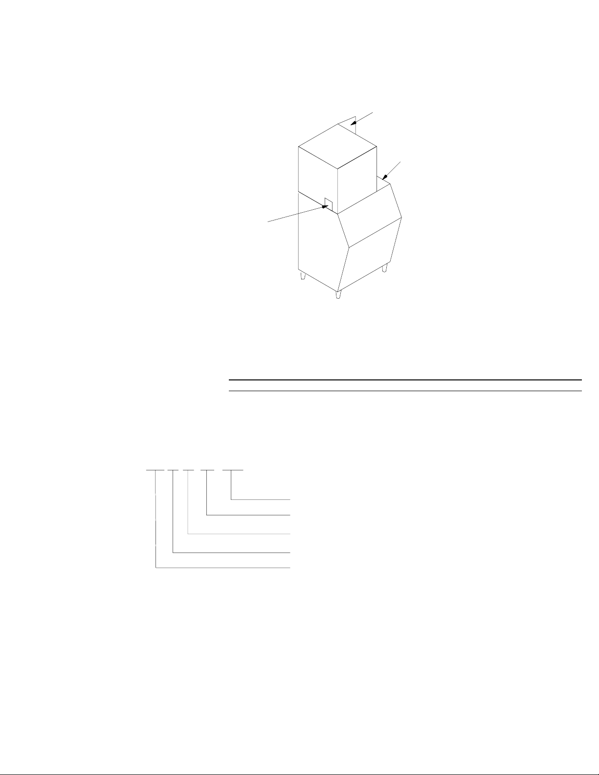
MODEL AND SERIAL LOCATION
“I” SERIES CUBER
Condenser Discharge Air
Deflector (as required)*
Bin Adapter (as required)*
Model/Serial
Number Location
*Bin adapters and condenser discharge air deflector may be equipped depending on your location or the size of
the storage bin.
Record the model number and the serial number of your ice equipment. These numbers are required when requesting information from your local dealer/distributor/service company.
Model Number – Date Installed –
Serial Number – Purchased From -
SERIAL NUMBER EXPLANATION
AA 95 01 BC 0001
Number – 4 digit number, 0001 – 9999
Product Code – 2 digit alpha
Month – 2 digit numerical month designation
Year – 2 digit year designation
Engineering Change Level – 1 or 2 alpha designation
12/1/94
Rev 3/4/96
1
166240004
Page 5
REMOTE CONDENSER SPECIFICATION
MODEL CR800 CR1200 CR1400
Volts 208/230 208/230 208/230
Phase 1 1 1
Hertz 60 60 60
Amps 1.0 1.0 1.0
Output, HP 1/6 1/6 1/6
Max. fuse size, Amps (HVAC circuit breaker
required)
20 20 20
ICE CUBER SPECIFICATION
MODEL
IAC322/330
IAC227
UNIT
Volts 115 115 115 115
Phase 1 1 1 1
Hertz 60 60 60 60
No. Wires 2+ground 2+ground 2+ground 2+ground
MIN. CIRCUIT
Amps 20 20 20 20
MAX FUSE SIZE (HVAC CIRCUIT BREAKER REQUIRED)
Amps 20 20 20 20
REFRIGERANT
Type R404A (HP62) R404A (HP62) R404A (HP62) R404A (HP 62)
Weight (oz) 17 15 26 23
Weight (g) 482 425 737 652
COMPRESSOR
Volts 115 115 115 115
Phase 1 1 1 1
Hertz 60 60 60 60
LRA 51 51 59 59
RLA 11.5 11.5 11.6 11.6
CONDENSER FAN MOTOR (Air-Cooled Systems only) of
AIR CIRCULATION FAN MOTOR (Water-Cooled and Remote Systems only)
Volts 115 115 115 115
Phase 1 1 1 1
Hertz 60 60 60 60
Amps Running 1.7 0.38 1.75 0.38
Watts 50 6 50 6
WATER PUMP
Volts 115 115 115 115
Phase 1 1 1 1
Hertz 60 60 60 60
Amps Running 0.88 0.88 0.76 0.88
HP 1/40 1/40 1/40 1/40
IWC322/330
IWCS227
IAC522/530 IWC522/530
166240004
2
12/1/94
Rev 3/4/96
Page 6

12/1/94
Rev 3/4/96
3
166240004
SPECIFICATIONS – 60 HZ
ICE CUBER SPECIFICATION
IAC322E60
MODEL
UNIT
Volts 230 230 230 230
Phase 1 1 1 1
Hertz 60 60 60 60
No. Wires 2+ground 2+ground 2+ground 2+ground
MIN. CIRCUIT
Amps 15 15 15 15
MAX FUSE SIZE (HVAC CIRCUIT BREAKER REQUIRED)
Amps 15 15 15 15
REFRIGERANT
Type R404A(HP62) R404A(HP62) R404A(HP62) R404A(HP 62)
Weight (oz) 17 15 26 23
Weight (g) 482 425 737 652
COMPRESSOR
Volts 230 230 230 230
Phase 1 1 1 1
Hertz 60 60 60 60
LRA 24.1 24.1 45 45
RLA 5.7 5.7 9.2 9.2
CONDENSER FAN MOTOR (Air-Cooled Systems only) or
AIR CIRCULATION FAN MOTOR (Water-Cooled and Remote Systems only)
Volts 230 230 230 230
Phase 1 1 1 1
Hertz 60 60 60 60
Amps Running 0.89 0.36 0.89 .036
Watts 50 6 50 6
WATER PUMP
Volts 230 230 230 230
Phase 1 1 1 1
Hertz 60 60 60 60
Amps Running 0.5 0.5 0.5 0.5
HP 1/30 1/30 1/30 1/30
IAC330E60
IACS227E60
IWC322E60
IWC330E60
IWCS227E60
IAC522E60
IAC522E60L
IAC530E60
IAC530E60L
IWC522E60
IWC522E60L
IWC530E60
IWC530E60L
Page 7
166240004
4
12/1/94
Rev 3/4/96
SPECIFICATIONS – 60 HZ
ICE CUBER SPECIFICATION
MODEL IAC630 IWC630 IRC630 IAC830 IWC830 IRC830
UNIT
Volts 230 230 230 230 230 230
Phase 1 1 1 1 1 1
Hertz 60 60 60 60 60 60
No. Wires 2+ground 2+ground 2+ground 2+ground 2+ground 2+ground
MIN. CIRCUIT
Amps 20 20 20 20 20 20
MAX FUSE SIZE (HVAC CIRCUIT BREAKER REQUIRED)
Amps 20 20 20 20 20 20
REFRIGERANT
Type R404A(HP62) R404A(HP62) R404A(HP62) R404A(HP62) R404A(HP62) R404A(HP62)
Weight (oz) 43 35 170 55 33 170
Weight (g) 1219 992 4820 1559 936 4820
COMPRESSOR
Volts 230 230 230 230 230 230
Phase 1 1 1 1 1 1
Hertz 60 60 60 60 60 60
LRA 69 69 69 61 61 61
RLA 8.8 8.8 8.8 12.5 12.5 12.5
CONDENSER FAN MOTOR (Air-Cooled Systems only) or
AIR CIRCULATION FAN MOTOR (Water-Cooled and Remote Systems only)
Volts 230 230 230 230 230 230
Phase 1 1 1 1 1 1
Hertz 60 60 60 60 60 60
Amps Running 1.09 0.36 0.36 1.09 0.36 0.36
Watts 75 6 6 75 6 6
WATER PUMP
Volts 230 230 230 230 230 230
Phase 1 1 1 1 1 1
Hertz 60 60 60 60 60 60
Amps Running 0.5 0.5 0.5 0.5 0.5 0.5
HP 1/30 1/30 1/30 1/30 1/30 1/30
Page 8
12/1/94
Rev 3/4/96
5
166240004
SPECIFICATIONS – 60 HZ
ICE CUBER SPECIFICATION
MODEL
UNIT
Volts 230 230 230
Phase 1 1 1
Hertz 60 60 60
No. Wires 2+Ground 2+Ground 2+Ground
MIN. CIRCUIT
Amps 20 20 20
MAX FUSE SIZE (HVAC CIRCUIT BREAKER REQUIRED)
Amps 20 20 20
REFRIGERANT
Type R404a(HP62) R404a(HP62) R404a(HP62)
Weight (oz) 60 42 210
Weight (g) 1701 1191 5954
COMPRESSOR
Volts 230 230 230
Phase 1 1 1
Hertz 60 60 60
LRA 82 82 82
RLA 13.0 13.0 13.0
CONDENSER FAN MOTOR (Air-Cooled Systems only) or
AIR CIRCULATION FAN MOTOR (Water-Cooled and Remote Systems only)
Volts 230 230 230
Phase 1 1 1
Hertz 60 60 60
Amps Running 0.892 0.36 0.36
Watts 50W2 6W 6W
WATER PUMP
Volts 230 230 230
Phase 1 1 1
Hertz 60 60 60
Amps Running 0.5 0.5 0.5
HP 1/30 1/30 1/30
IAC1030
IAC1030L
IWC1030
IWC1030L
IRC1030
IRC1030L
Page 9

166240004
6
12/1/94
Rev 3/4/96
SPECIFICATIONS – 60 HZ
ICE CUBER SPECIFICATION
MODEL IAC1230 IWC1230 IRC1230 IAC1448 IWC1448 IRC1448
UNIT
Volts 230 230 230 230 230 230
Phase 1 1 1 1 1 1
Hertz 60 60 60 60 60 60
No. Wires 2+ground 2+ground 2+ground 2+ground 2+ground 2+ground
MIN. CIRCUIT
Amps 20 20 20 25 25 25
MAX FUSE SIZE (HVAC CIRCUIT BREAKER REQUIRED)
Amps 20 20 20 25 25 25
REFRIGERANT
Type R404A(HP62) R404A(HP62) R404A(HP62) R404A(HP 62) R404A(HP 62) R404A(HP 62)
Weight (oz) 49 45 210 92 44 250
Weight (g) 1389 1276 5954 2608 1247 7088
COMPRESSOR
Volts 230 230 230 230 230 230
Phase 1 1 1 1 1 1
Hertz 60 60 60 60 60 60
LRA 96 96 96 95.6 95.6 95.6
RLA 13.5 13.5 13.5 23.9 23.9 23.9
CONDENSER FAN MOTOR (Air-Cooled Systems only) or
AIR CIRCULATION FAN MOTOR (Water-Cooled and Remote Systems only)
Volts 230 230 230 230 230 230
Phase 1 1 1 1 1 1
Hertz 60 60 60 60 60 60
Amps Running 0.89 X 2 0.36 0.36 0.4 0.36 0.36
Watts 50 W X 2 6 W 6 W 1/15 HP 6 W 6 W
WATER PUMP
Volts 230 230 230 230 230 230
Phase 1 1 1 1 1 1
Hertz 60 60 60 60 60 60
Amps Running 0.5 0.5 0.5 0.5 0.5 0.5
HP 1/30 1/30 1/30 1/30 1/30 1/30
Page 10

12/1/94
Rev 3/4/96
SPECIFICATIONS – 50 HZ
7
166240004
IAC322E50
MODEL
UNIT
Volts 220 220 220 220
Phase 1 1 1 1
Hertz 50 50 50 50
No. Wires 2+ground 2+ground 2+ground 2+ground
MIN. CIRCUIT
Amps 15 15 15 15
MAX FUSE SIZE (HVAC CIRCUIT BREAKER REQUIRED)
Amps 15 15 15 15
REFRIGERANT
Type R404A(HP62) R404A(HP62) R404A(HP62) R404A(HP 62)
Weight (oz) 17 15 26 23
Weight (g) 482 425 737 652
COMPRESSOR
Volts 220 220 220 220
Phase 1 1 1 1
Hertz 50 50 50 50
LRA 26 26 33 33
RLA 5.3 5.3 8.2 8.2
CONDENSER FAN MOTOR (Air-Cooled Systems only) or
AIR CIRCULATION FAN MOTOR (Water-Cooled and Remote Systems only)
Volts 220 220 220 220
Phase 1 1 1 1
Hertz 50 50 50 50
Amps Running 0.75 0.3 0.75 0.3
Watts 50 6 50 6
WATER PUMP
Volts 220 220 220 220
Phase 1 1 1 1
Hertz 50 50 50 50
Amps Running 0.5 0.5 0.5 0.5
HP 1/30 1/30 1/30 1/30
IAC330E50
IACS277E50
IWC322E50
IWC330E50
IWCS227E50
IAC522E50
IAC522E50L
IAC530E50
IAC530E50L
IWC522E50
IWC522E50L
IWC530E50
IWC530E50L
Page 11
166240004
SPECIFICATIONS – 50 HZ
8
12/1/94
Rev 3/4/96
MODEL
UNIT
Volts 220 220 220 220 220 220
Phase 1 1 1 1 1 1
Hertz 50 50 50 50 50 50
No. Wires 2+ground 2+ground 2+ground 2+ground 2+ground 2+ground
MIN. CIRCUIT
Amps 20 20 20 20 20 20
MAX FUSE SIZE (HVAC CIRCUIT BREAKER REQUIRED)
Amps 20 20 20 20 20 20
REFRIGERANT
Type R404A(HP62) R404A(HP62) R404A(HP62) R404A(HP 62) R404A(HP 62) R404A(HP 62)
Weight (oz) 43 35 170 55 33 170
Weight (g) 1219 992 4820 1559 936 4820
COMPRESSOR
Volts 220 220 220 220 220 220
Phase 1 1 1 1 1 1
Hertz 50 50 50 50 50 50
LRA 53 53 53 58 58 58
RLA 8 8 8 12 12 12
CONDENSER FAN MOTOR (Air-Cooled Systems only) or
AIR CIRCULATION FAN MOTOR (Water-Cooled and Remote Systems only)
Volts 220 220 220 220 220 220
Phase 1 1 1 1 1 1
Hertz 50 50 50 50 50 50
Amps Running 1.06 0.3 0.3 1.06 0.3 0.3
Watts 75 6 6 75 6 6
WATER PUMP
Volts 220 220 220 220 220 220
Phase 1 1 1 1 1 1
Hertz 50 50 50 50 50 50
Amps Running 0.5 0.5 0.5 0.5 0.5 0.5
HP 1/30 1/30 1/30 1/30 1/30 1/30
IAC630E50
IAC630E50L
IWC630E50
IWC630E50L
IRC630E50
IRC63050L
IAC830E50
IAC830E50L
IWC830E50
IWC830E50L
IRC830E50
IRC830E50L
Page 12
12/1/94
Rev 3/4/96
SPECIFICATIONS – 50 HZ
9
166240004
MODEL
UNIT
Volts 220 220 220 220 220 220
Phase 1 1 1 1 1 1
Hertz 50 50 50 50 50 50
No. Wires 2+ground 2+ground 2+ground 2+ground 2+ground 2+ground
MIN. CIRCUIT
Amps 20 20 20 25 25 25
MAX FUSE SIZE (HVAC CIRCUIT BREAKER REQUIRED)
Amps 20 20 20 25 25 25
REFRIGERANT
Type R404A(HP62) R404A(HP62) R404A(HP62) R404A(HP 62) R404A(HP 62) R404A(HP 62)
Weight (oz) 49 45 210 92 44 250
Weight (g) 1389 1276 5954 2608 1247 7088
COMPRESSOR
Volts 220 220 220 220 220 220
Phase 1 1 1 1 1 1
Hertz 50 50 50 50 50 50
LRA 64 64 64 75.9 75.9 75.9
RLA 12.5 12.5 12.5 13 13 13
CONDENSER FAN MOTOR (Air-Cooled Systems only) or
AIR CIRCULATION FAN MOTOR (Water-Cooled and Remote Systems only)
Volts 220 220 220 220 220 220
Phase 1 1 1 1 1 1
Hertz 50 50 50 50 50 50
Amps Running 0.752 0.3 0.3 0.752 0.3 0.3
Watts 0.50W2 6W 6W 0.75W2 6W 6W
WATER PUMP
Volts 220 220 220 220 220 220
Phase 1 1 1 1 1 1
Hertz 50 50 50 50 50 50
Amps Running 0.5 0.5 0.5 0.5 0.5 0.5
HP 1/30 1/30 1/30 1/30 1/30 1/30
IAC1030E50
IAC1030E50L
IWC1030E50
IWC1030E50L
IRC1030E50
IRC103050L
IAC1230E50
IAC1230E50L
IWC1230E50
IWC1230E50L
IRC1230E50
IRC1230E50L
Page 13

166240004
10
SPECIFICATIONS – 50 HZ, REMOTE CONDENSER
MODEL CR800E50 CR1200E50 CR1400E50
UNIT
Volts 220 220 220
Phase 1 1 1
Hertz 50 50 50
Amps 1.1 1.1 1.1
Output H.P. 1/6 1/6 1/6
MAX fuse size, Amps
(HVAC circuit breaker required
20 20 20
12/1/94
Rev 3/4/96
Page 14

GENERAL
FREIGHT DAMAGE CLAIMS PROCEDURE
The deliverer of your equipment (freight company, distributor or dealer) is responsible for loss or damage of your
shipment. All claims must be filed with the deliverer of your equipment. Please follow the steps below to determine if your shipment is satisfactory or if a claim must be filed:
1. Check the number of products delivered against the number of products listed on the delivery receipt.
Should the totals not match, have the driver note all errors on both copies and both you and the driver sign
and date said notation.
2. Inspect all cartons for visible damage. Open and inspect as required before the driver leaves and have him
or her note any damage on the receipts. All damaged claims must be inspected within 15 days of delivery.
Notify your carrier immediately if concealed damage is found after delivery.
3. Should concealed damage be found when product is unpacked, retain the packing material and the product
and request an inspection from the deliverer.
4. All claims for loss or damage should be filed at once. Delays in filing will reduce the chance of achieving a
satisfactory resolution to the claim.
12/1/94
Rev 3/4/96
11
166240004
Page 15
INSTALLATION INSTRUCTIONS
Installation and start-up of the equipment should be performed by the distributor or the dealer’s professional
staff.
LOCATION OF EQUIPMENT
For maximum performance the location should be away from heat sources such as ovens, direct sunlight, hot
air discharge, etc.
To reduce cost of maintenance and loss of efficiency, avoid placing air-cooled equipment in areas where grease,
flour and other airborne contaminants are present. Allow a minimum of 6I (15.24 cm) clearance on all sides and
top for proper air circulation. Restricted air circulation will affect the efficiency and required maintenance of the
product.
IMPORTANT: Never operate your equipment in room temperature below 50_F (10_) or above 100_ F
(38_C). Should the location of your product ever be exposed to freezing temperatures, it must be shut
down and winterized.
EQUIPMENT SET-UP
The following steps refer to the set-up of the ice bin and the cuber:
1. Remove the bin from its carton, place it on its back and install the legs into the bottom of the bin. Bins must
be installed on legs or sealed to the floor with RTV-732 sealant.
2. Set the bin up on its legs. Place the bin in its final location and level it with the adjustable feet in the legs.
3. Unpack the cuber from its carton, and set in place on the bin and adjust as required. Leave all panels on
the cuber until it is set in place on the dispenser or bin.
4. Remove all internal packing from the cuber.
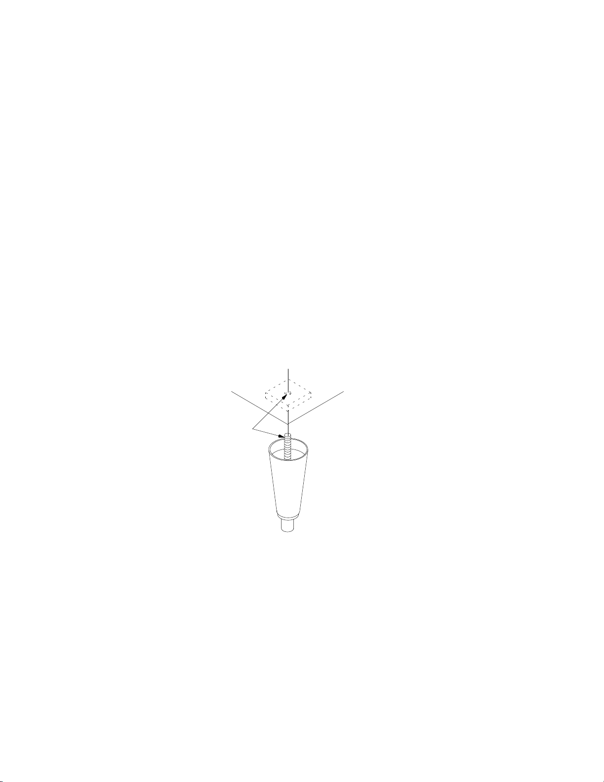
THREAD LEVELING
LEG INTO BASE
NOTE: Bin adapter andcondenser air baffles may be required in certain installations.
DISPENSER INSTALLATION
The proper cuber/dispenser installation package should be ordered. This package will include gasket material
and hold-down bracket.
166240004
12
12/1/94
Rev 3/4/96
Page 16

R
D
A
(
E
0
0
R
IACS/IWCS 227
C
25.06
6.0 MIN
15.25
27.00
28.00
33.00
31.38
21.38
31.38
21.38
7.06
7.06
A
B
D
1.00(3)
IACS 227
REAR VIEW
C
A
B
E
F
2.06
1.00(5)
IWCS 227
REAR VIEW
1. LAY CABINET ON BACK OR SIDE USING BLANKET O
2. REMOVE CRATE SKID FROM UNIT BOTTOM.
3. SCREW ADJUSTABLE LEGS INTO RECESSED THREA
4. LEVEL UNIT USING FEET FOR ADJUSTMENT.
8.75
D
8.75
INSTRUCTIONS FOR ATTACHING SUPPORT LEGS
PADDING TO AVOID MARRING.
A ELECTRICAL CORD ATTACHED (2
B 3/4 DRAIN – TUBING SIZE 5/8 I.D.
C 3/8 WATER INLET (SEA MALE FLA
D 3/4 BIN DRAIN – STD PIPE SAE
2.25
A ELECTRICAL CORD ATTACHED (2
B 3/4 DRAIN – TUBING SIZE 5/8 I.D.
C 3/8 RESERVOIR WATER INLET (SA
D 3/4 BIN DRAIN – STD PIPE SAE
E 5/8 CONDENSER WATER OUTLET
F 5/8 CONDENSER WATER INLET (M
2.25
12/1/94
Rev 3/4/96
13
LEGS (4)
BLANKET
166240004
Page 17
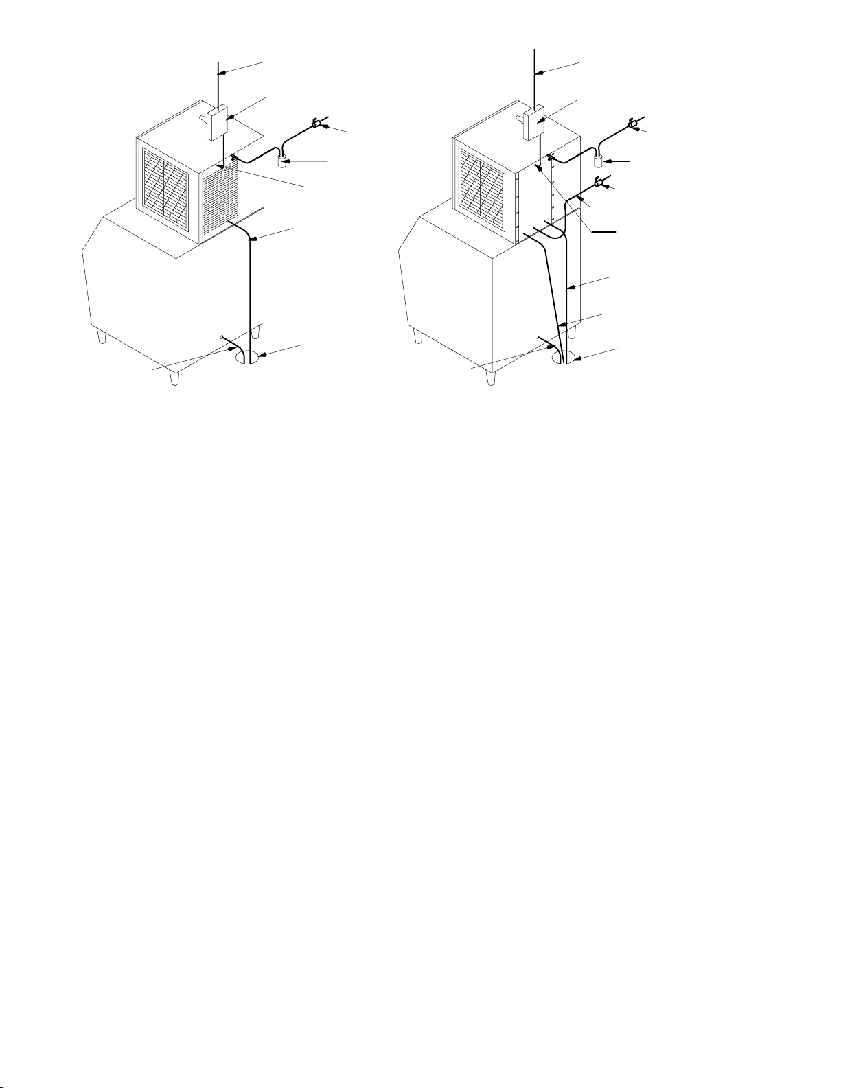
Electrical Service
Line
Manual Disconnect
Switch
Shut-Off
Water Filter
Valve
Electrical Service
Line
Manual Disconnect
Switch
Shut-Off Valve
Water Filter
Bin Drain
Tube
AIR-COOLED MODELS
STRAIN RE-
LIEF
MUST BE
USED
Dump
Valve
Drain Tube
Floor
Drain
Bin Drain
Tube
WATER-COOLED MODELS
Shut-Off Valve
Condenser Water Inlet
Strain Relief
must be used
Dump Valve
Drain Tube
Condenser Water
Drain Tube
Floor
Drain
Note: Leave all panels on the cuber until it is in place on the bin.
PLUMBING CONNECTIONS
1. All plumbing lines and connections must conform to local and
national plumbing codes.
2. Line shut-off valves must be located in supply water lines for cuber and condenser if product is watercooled. Water supply to water-cooled condenser must include a stand-pipe to prevent “water
hammer”.
3. Should your local water supply quality require the installation of a water filter system, consult your local distributor or dealer for proper size required.
4. Water supply pressure must not be lower than 20 PSI (1.37 BAR), nor should it exceed 120 PSI (8.16
BAR).
NOTE: Water filters larger then 5 microns do not give proper protection. Water pressures above 80
PSI (5.44 BAR) will destroy the filter.
DRAIN LINES: Bin and cuber drain lines must never be connected together and must be vented.
NOTE: All HP-62 (R404A) ice machines have a voltage range of –5%, +10% from the serial palte rating.
ELECTRICAL
1. All wiring and connections must conform to national and local electrical codes.
2. Wire size and circuit protection must conform to specifications and cuber must be on a separate electrical
circuit.
3. Strain relief connectors must be used at the junctions box of the control box and the cuber.
4. Cuber must be grounded by the control box ground screw or other method for intentional safety grounding
that meets code requirements.
5. A manual disconnect in a convenient location to the cuber must be installed.
INSTALLATION CHECK POINTS
1. Has bin and cuber been leveled and sanitized?
2. Does electrical and plumbing meet code requirements?
3. Check correct operating water level in the water pan.
166240004
14
12/1/94
Rev 3/4/96
Page 18
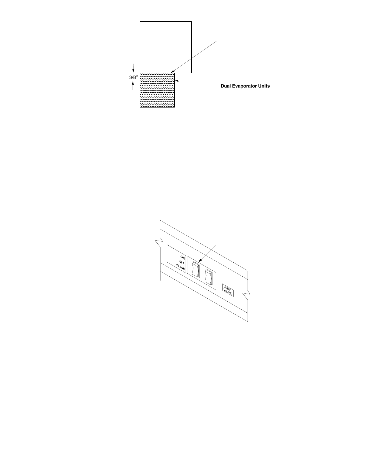
operating water level
Single Evaporator Units
3/8I
WATER PAN
RIGHT SIDE VIEW
operating water level
Dual Evaporator Units
4. If water-cooled, are inlet and drain connections to condenser correct to prevent “water hammer”?
5. Are drain lines separate and vented?
6. Is there 6I clearance on all sides and top for proper air circulation?
7. Does the water curtain move freely, and does the float valve shut off incoming water to the water pan?
START-UP AND CHECK OUT
1. Turn the Cuber’s power switch to the clean (pump only) position. The water pump only should be opera-
tional. Wipe the top extrusion briskly with a ScotchBrite pad. Check for an even, steady flow of water over
evaporator top extrusion and down over evaporator surface. Check that all ports of the water distribution
tube are open for even water discharge. The water pan should refill and the float should stop the incoming
water supply.
Power Switch
NOTE: On the IACS222/IWCS227 to service the float valve:
1. Compress the John Guess fitting remove the 1/4” tubing.
2. Remove the screws that hold the float bracket to the liner wall.
3. Carefully remove float strainer and bracket as one assembly.
4. Reverse procedure to reinstall.
Should service be required on the float valve or strainer, turn the water supply off, loosen the float,
hold down nut and remove the float and strainer as an assembly for ease of service.
2. Place the Cuber’s power switch in the ON position. After a 2-second delay the compressor will start. The
condenser fan will operate when the condenser sensor signals the circuit board its temperature is 100_F
(38_C). The water pump will operate when the evaporator cools to 25_F (–3.9_C). Depress the manual
harvest switch (on the circuit board). The fan motor will stop and the water dump valve will open. In 3 seconds the hot gas solenoid will open and 15 seconds after depressing the manual harvest switch, the water
pump and dump valve will close terminating the dump cycle.
3. Hold the water curtain open for a maximum of 30 seconds; the Cuber should shut down. Release the water
curtain(s). When the curtain(s) closes, there will be a 2-second delay, then the compressor will start and
the start-up process should begin for the next ice-making mode.
4. If all Cuber operation is as stated, allow product to operate and produce one slab of ice, then discard the
ice. Allow the Cuber to continue operation to fill the storage bin.
12/1/94
Rev 3/4/96
15
166240004
Page 19
OWNER -OPERATOR
The installation is not complete until you are sure the owner-operator understands the cuber operation and his
or her responsibility of preventative maintenance.
Does the owner-operator know:
1. Location of electrical disconnect switch and water shut-off valves?
2. How to start and/or shut down the product, clean and sanitize it?
3. Bin full operation and reset operation of high pressure cutout (water-cooled and remote products only)?
4. How to clean the condenser and fan blade?
5. Whom to call for product information and/or service?
CLEANING PROCEDURES
Approved ice machine cleaners by brand names:
S Lime–A–Way
S Calgon Nickel Safe (green color only)
NOTE: All ice machine cleaners labeled safe for nickel ARE NOT the brand CALGON NICKEL SAFE.
CAUTION: Ice machine cleaners are acidic-based chemicals. Before beginning any
cleaning of the cuber, the ice in the storage bin or dispenser must be removed.
WARNING: When using any chemical, rubber gloves and eye protection should be worn.
PREP – CLEANING
Use full-strength ice machine cleaner on a coarse-surface cloth material (such as terry cloth) and wipe down the
inside wall of the evaporator area, the water pan, the water curtain and evaporator plastic extrusions. If the water distributor tube has heavy scale build-up, remove and soak it in full-strength ice machine cleaner (or exchange the tube and clean the scaled tube at a later date).
Cleaning the Water System and Evaporator
1. Set the switch to Clean and allow any ice on the evaporator to release and melt away.
2. Remove all ice from the storage bin.
3. Remove the water curtain(s), pour 1/2 oz. of ice machine cleaner down the rear key-slot openings. The
cleaner will drain into the water pan.
4. Return the water curtain(s) to their proper operating positions.
5. Add 3 oz. for a single evaporator, or 5 oz. for a dual evaporator of “Calgon Nickel Safe” or “Lime-A-Way”
ice machine cleaner directly into the water pan. The float will balance with inlet water. Set switch to
CLEAN, circulate for a maximum of 15 minutes.
6. Depress and hold the dump switch to allow the cleaner to drain away.
7. Fill the water pan with clean fresh water, circulate for approximately 3 minutes. Depress and hold the
DUMP switch and allow the water to drain away. Repeat the procedure 3 times.
8. After third rinse cycle, place product power switch in ice position. Allow Cuber to produce one slab of ice –
DISCARD THE ICE.
9. When the clean cycle is complete, return cuber to normal operating mode.
NOTE: Please Take Note of the Following:
S Ice machines should only be cleaned when needed, not by a timed schedule of every 60 days, etc.
S Should your ice machine require cleaning more than twice a year, consult your distributor or dealer about
proper water treatment.
166240004
16
12/1/94
Rev 3/4/96
Page 20
Power Switch
SANITIZING PROCEDURES
NOTE: To be performed only after cleaning the ice machine:
1. Add 1/4 ounce (7.08 g) sodium hypochlorite solution (common liquid laundry bleach) to the water pan and
allow the pump to circulate the solution for 5 minutes. You may also use a commercial sanitizer such as
Calgon Ice Machine Sanitizer following the directions on the product label.
2. Turn the Cuber power switch off and depress and hold the dump switch to drain the water pan.
3. To sanitize the bin and other surface areas, use 1 ounce of liquid bleach per gallon of water and wipe all
areas with the solution. Or use a commercial sanitizer.
4. Place the Cuber power switch in the ice position. Discard the first batch of ice produced.
5. Cleaning and sanitizing are now complete. Cuber may be returned to normal service.
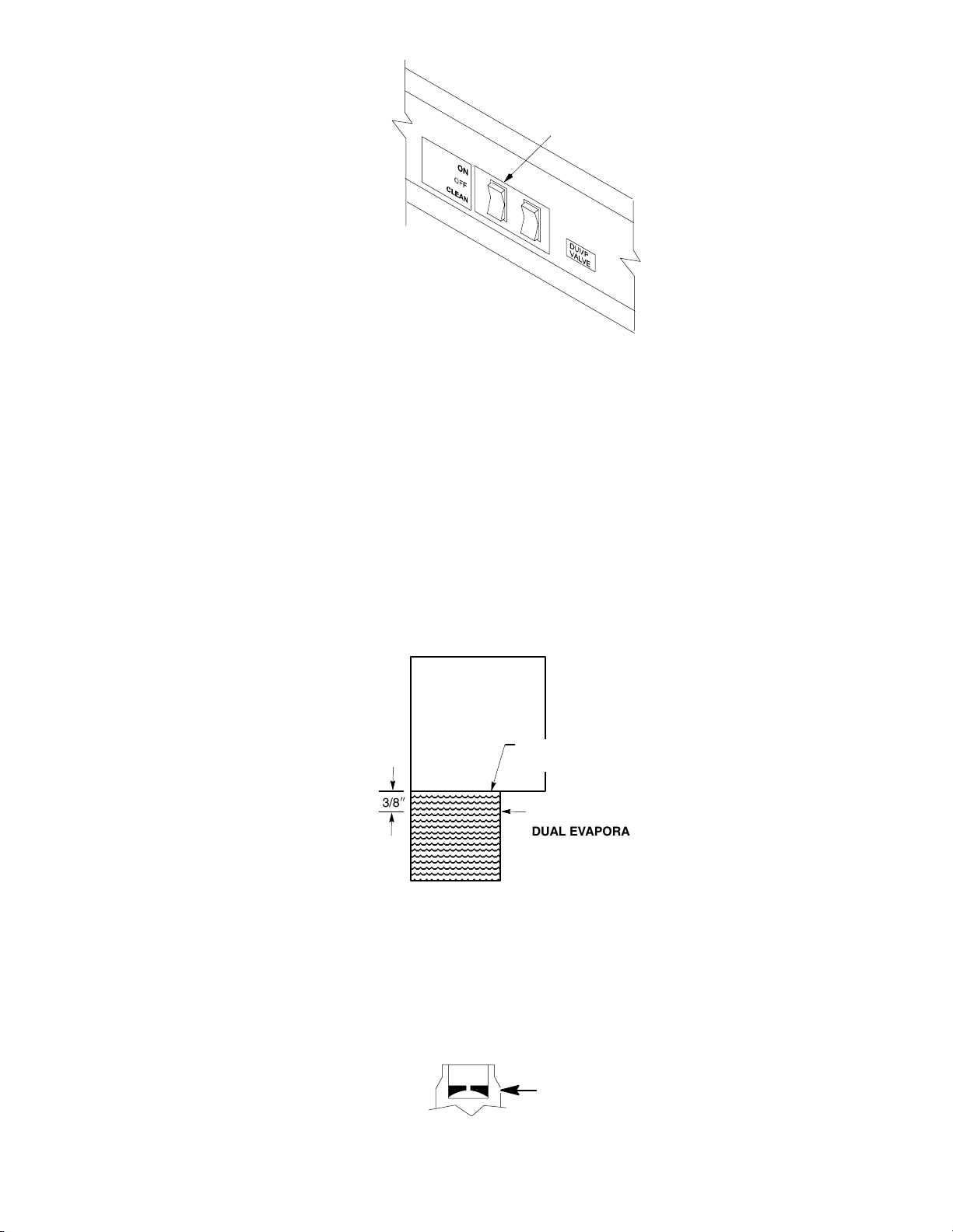
DUMP CYCLE
OPERATING WATER LEVEL
SINGLE EVAPORATOR UNITS
3/8I
WATER PAN
RIGHT SIDE VIEW
1. With the proper water level in the water pan, start the water pump to circulate the water. Check that the
float will return water level to original setting and stop inlet water.
2. There is a flow washer in the inlet side of the float assembly that will control inlet water pressure from
20/120 PSI (3.4/8.16 Bars). This will prevent float flutter. In low water pressure conditions, 20 PSI (1.37
Bars) or less, the flow washer may have to be removed from the float assembly for proper volume.
OPERATING WATER LEVEL
DUAL EVAPORATOR UNITS
FLOW CONTROL WASHER FLAT SIDE UP
3. Push the manual dump switch – allow dump action to drain the water pan. When you release the momentary switch, the pump will stop and the float will return the water level back to its original setting and shut off
the water supply.
12/1/94
Rev 3/4/96
17
166240004
Page 21
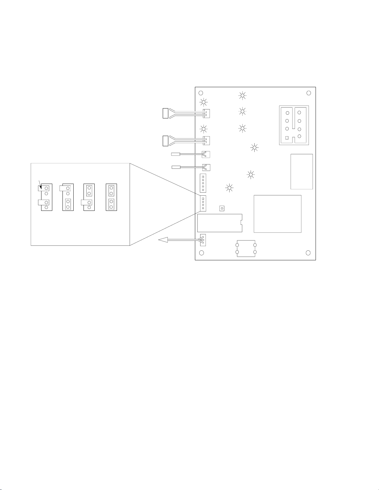
4. You have the option of selecting dump cycle intervals of:
)
S every cycle; (Standard setting from factory)
S every 3rd cycle;
S every 5th cycle;
S every 7th cycle.
Remember, the higher the mineral content in the water supply the more often it will be required to dump the water and/or clean the product if proper water treatment is not used.
Water
YL
RH Evap.
LH Evap.
Condenser
plug
Suction plug
RD
Error
Adjustable Ice
Thickness Pot.
DĆ15
DĆ14
DĆ12
DĆ5
Dump
Valve
GR
Fan
GR
Manual
Harvest
Switch
Contactor
Water
Pump
Hot Gas
DĆ11
DĆ6
7
5
3
1
Transformer
8
6
4
2
Voltage
Selector
Switch
230v
neutral
115v
Sleeve Connector
Dump
Every
Cycle
Options Plug
Dump
Every
3rd
Cycle
Dump
Every
5th
Cycle
Dump
Every
7th
Cycle
RH Evap.
Switch
Suction Line Sensor
N
S
LH Evap. Switch
N
S
Condenser Sensor
White
Brown
To Stacked
Unit
(if required
DĆ13
YL
DĆ10
Test
Plug
Options
Plug
Micro Processor
Stacking
Cable
Plug
166240004
18
12/1/94
Rev 3/4/96
Page 22

ADJUSTING BRIDGE THICKNESS
TOP ROW
3/8I - 5/8I DIMPLE
CENTER
1/8I BRIDGE
BOTTOM 2 ROWS
3/16I - 1/4I BRIDGE
For optimum ice production and maximum cube separation, the ice
connecting the individual cubes should be a minimum of 1/8I (.32cm)
thick at the center area of the ice waffle.
BRIDGE 1/8I (0.32 cm)
It is normal for the ice slab to be slightly thicker at the bottom and taper
off in a slight wedge pattern at the top. The top row of cubes must have
a complete pattern of ice on all four sides and the back wall. Remember, when you operate the product with the panels off during testing the
additional heat at the top of the evaporator will cause thinner ice at the
top than when the panels are in place.
Should a different thickness of the bridge be desired, it will be required
to adjust the ice thickness “POT”, located on the circuit board, as follows:
1. Thinner Bridge – turn the ice thickness “pot” adjustment screw
CW one full turn. Allow two cycles before determining if
additional adjustments are required.
2. Thicker Bridge – turn the ice thickness “pot” adjusting screw CCW
one full turn. Allow two cycles before determining if additional adjustments are required.
NOTE: Never judge the thickness of the ice from the first batch of the ice produced – the first cycle is
a balance cycle. Always wait for the second cycle before making any adjustments.
TOTAL ICE CAPACITY
Ice capacity of any ice maker is affected by many operating conditions, such as water and air temperature and
location factors. Please review the capacity tables in this manual for average 24-hour capacity under various
conditions.
NOTE: All printed capacity ratings are 10% except 50 HZ units. These products have 12% increase
in cycle time and capacity decrease of approximately 17%.
ICE PRODUCTION CHECK
If air cooled, take air temperature at the intake of the condenser, 2I from the condenser fins, and Incoming water temperature at the outlet of the “float” valve.*
Cycle time (CT) = freeze time plus harvest time, in minutes and seconds. 1440 divided by CT = number of
cycles per 24 hours.
Measure weight of ice from one cycle in pounds and fractions of a pound.
EXAMPLE: Weight/cycle x cycles/day = total production/24 hrs. Compare to the production tables.
* If water cooled, be certain water regulator valve is set to maintain 300/310 PSI head pressure.
12/1/94
Rev 3/4/96
19
166240004
Page 23
RH Evap. Switch
N
S
LH Evap. Switch
N
S
Condenser Sensor
Suction Line Sensor
White
Brown
DĆ13
YL
RH Evap.
YL
DĆ10
LH Evap.
Condenser
plug
Suction plug
Test
Plug
Options
Plug
Micro Processor
DĆ15
DĆ14
DĆ12
RD
DĆ5
Error
Adjustable Ice
Thickness Pot.
Water
Dump
Valve
Contactor
Water
Pump
GR
DĆ11
Fan
GR
DĆ6
Hot Gas
7
5
3
1
Transformer
8
6
4
2
Voltage
Selector
Switch
230v
neutral
115v
Stacking
Cable
Plug
To Stacked Unit
(if required)
Manual
Harvest
Switch
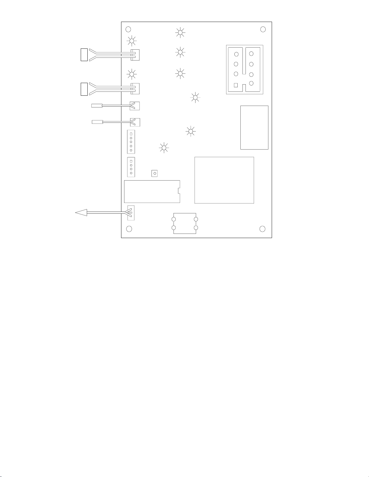
LED INDICATORS
The LEDs are board circuit indicators. If the LED in the functional board circuit is complete, check component.
Example: Contactor does not energize and LED is “ON”, board circuit is OK. Check contactor, coil, leads, &
connections.
Yellow:
S Evaporator switch(s) (proximity)
Green:
S Water dump valve
S Compressor contactor
S Water Pump
S Hot Gas Valve
S Condenser Fan (cycles on & off with fan)
Red:
Error in system operation. Product shut down.
166240004
20
12/1/94
Rev 3/4/96
Page 24
STATUS INDICATOR
D6 Green LED Condenser Fan
D10 Yellow LED Left Water Curtain
D11 Green LED Hot Gas Valve
D12 Green LED Water Pump
D13 Yellow LED Right Water Curtain
D14 Green LED Compressor Contactor
D5 Red LED Error
D15 Green LED Dump Valve
Curtain Open
D13 Yellow LED off Right evaporator curtain open.
D10 Yellow LED off Left evaporator curtain open.
Pre-Chill Mode
D6 Green LED (on or off) Condenser fan cycles on & off depending upon condenser temperature.
D14 Green LED (on) Compressor contactor active - Compressor running.
D13 Yellow LED (on) Right evaporator curtain closed.
D10 Yellow LED (on) Left evaporator curtain closed (only if unit has two evaporators).
Ice-Making Mode
D6 Green LED (on or off) Condenser fan cycles on and off depending upon condenser temperature.
D12 Green LED (on) Water pump active.
D14 Green LED (on) Compressor contactor active - compressor running.
D13 Yellow LED (on) Right evaporator curtain closed.
D10 Yellow LED (on) Left evaporator curtain closed (only if unit has two evaporators).
Harvest Mode
D11 Green LED (on) Three seconds after water dump valve becomes active, the hot gas valve becomes active.
D12 Green LED (on) 15 sec. Fifteen seconds after water dump valve becomes active, the water pump deactivates.
D14 Green LED (on) Compressor contactor active - compressor running.
D15 Green LED (on) 15 sec. Water dump valve becomes active at the start of harvest. Water dump valve is active for
D13 Yellow LED (on) Right evaporator curtain closed. When the ice falls and the curtain opens, the LED will turn off.
D10 Yellow LED (on) Same as D13 if there is a second (left) evaporator.
15 seconds.
Error LED
D5 Red LED (on) EVAPORATOR OPEN THERMISTOR CIRCUIT Ć thermistor open / broken wire / poor connection.
D5 Red LED (on) EVAPORATOR HIGH TEMP. ERROR: Six minutes into the Freeze cycle the suction line temperaĆ
D5 Red LED (on) TWO REPEATED FAILED HARVEST CYCLES Ć No ice drop.
D5 Red LED Flashing, 1/sec CONDENSER OPEN THERMISTOR CIRCUIT (Air Cooled only) Ć Thermistor open / broken wire /
D5 Red LED Flashing, 1/sec CONDENSER LOW TEMPERATURE CONDITION. Ć Condenser midpoint reaches 36°F Ć Ice
D5 Red LED Flashing, 1/sec CONDENSER HIGH TEMPERATURE SAFETY SHUT DOWN.
Ice maker is SHUT DOWN. Consult service manual (Diagnostic Section) for troubleshooting
guide.
ture failed to reach 40°F or below. Ice Maker is SHUT DOWN. Consult service manual (Diagnostic
Section) for troubleshooting guide.
poor connection. Ice Maker is SHUT DOWN. Consult service manual (Diagnostic Section) for
troubleshooting guide.
Maker is SHUT DOWN.
12/1/94
Rev 3/4/96
21
166240004
Page 25
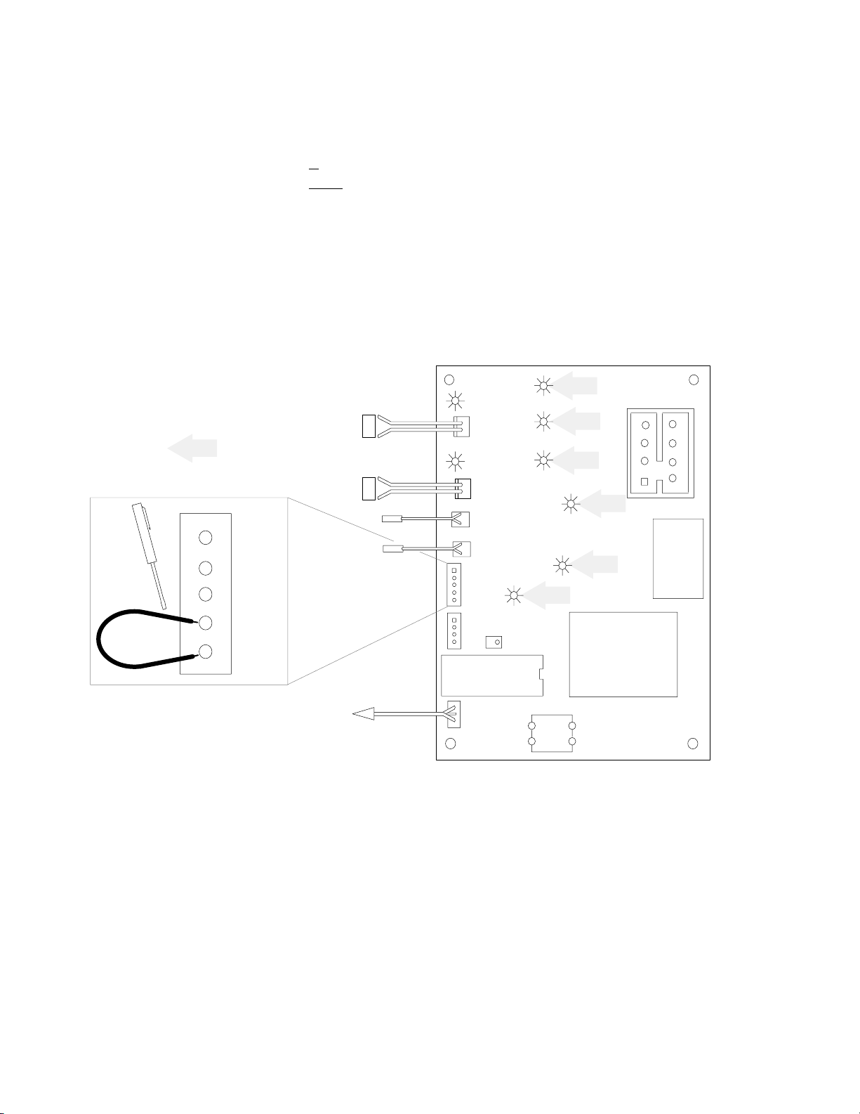
CIRCUIT BOARD DIAGNOSTIC PROCEDURE
Turn the power switch to the “ON” position. The D-5 red LED (error indicator) will be illuminated for 2 seconds.
After the D-5 red LED goes out, short across the bottom two terminals of the Test Plug with a jumper wire or a
pocket screwdriver and then remove the jumper. The circuit board is now in the test mode.
One of these two conditions will exist:
S If the Ice Thickness Potentiometer is within the factory setting the D-5, red LED will flash continiously.
S If the Ice Thickness Potentiomater is not
In either case the Green LED indicators will illuminate for 2 seconds each in the sequence shown below. They
will continue to sequence until you turn the power off and stop the procedure.
D-11 Green Hot Gas
D-12 Green Water Pump
D-14 Green Contactor
D-6 Green Fan
D-15 Green Dump Valve
Failure of the green LED’s to cycle in this sequence indicates a defect in the circuit board.
LED Indicators
Test
Plug
within the factory setting, the D-5 red LED will not be illuminated.
Water
RH Evap. Switch
N
S
LH Evap. Switch
N
S
Condenser Sensor
Suction Line
Sensor
White
Brown
DĆ13
YL
YL
DĆ10
Test
Plug
Options
Plug
DĆ14
RH Evap.
LH Evap.
Condenser
plug
Suction plug
RD
Error
Adjustable Ice
Thickness Pot.
DĆ15
DĆ12
DĆ5
Dump
Valve
Contactor
Water
Pump
GR
DĆ11
Fan
GR
DĆ6
Hot Gas
Transformer
7
5
3
1
8
6
4
2
Voltage
Selector
Switch
166240004
To Stacked
Unit
(if required)
22
Micro Processor
Stacking
Cable
Plug
Manual
Harvest
Switch
12/1/94
Rev 3/4/96
Page 26

RESTORING ICE THICKNESS POTENTIOMETER TO FACTORY SETTING
1. Turn cuber power switch to the OFF (center) position.
2. Unplug the proximity switch(es) and the thermistor(s) from the circuit board.
3. Turn the cuber power switch to the ON position. The red LED D-5 will illuminate for 2 seconds and then go
out.
4. Short across the bottom 2 pins of the Test Plug using a wire jumper or a pocket screwdriver. Immediately
remove the jumper.
One of these two conditions will exist:
S If the Ice Thickness Potentiometer is within the factory setting the D-5, red LED will flash continiously.
S If the Ice Thickness Potentiomater is not within the factory setting, the D-5 red LED will not be illuminated.
In either case the Green LED indicators will illuminate for 2 seconds each in the sequence shown below. They
will continue to sequence until you turn the power off and stop the procedure.
D-11 Green Hot Gas
D-12 Green Water Pump
D-14 Green Contactor
D-6 Green Fan
D-15 Green Dump Valve
Making Adjustments
When making adjustments, turn the Ice Thickness Potentiometer screw slowly to allow the circuit board time to
react. Always turn the screw one full 360_ turn, rest several seconds, then adjust another 360_ turn.
Turn the Ice Thickness Potentiometer screw 10 (ten) turns clockwise or until the red LED D-5 starts to flash –
should the LED not start to flash after 10 (ten) turns clockwise – reverse the direction and turn the screw slowly
counterclockwise until the red LED D-5 starts to flash.
When the LED starts to flash, stop turning. You have reached the original factory setting.
Important: Erratic component operation (water pump, condenser fan, hot gas valves, etc.) are usually a
result of a poor connection at the 8-pin connector. Before doing any diagnostic test on the control
board, be sure to check the 8-pin connector to ensure that all wires are properly installed and the
connector is securely in place.
12/1/94
Rev 3/4/96
23
166240004
Page 27

COMPONENT FUNCTION (CIRCUIT BOARD ETC.)
TEST PLUG
Board manufactures check point. DO NOT ATTEMPT ANY VOLTAGE CHECKS AT THESE PINS.
SENSORS
Condenser sensor (WHITE) and suction line sensor (BROWN) are thermistors rated 1k ohm at room temperature.
S Condenser sensor signals the circuit board for fan cycling and also serves as the high temperature safety
shut down. The red “Error LED” will flash on and off every second, during high temperature safety shut
down. Product is functionally shut down. Reset procedure must be performed to restart product operation.
S Suction line sensor signals the circuit board the suction line temperature, to control ice bridge thickness.
Also the sensor serves as suction line high temperature signal (Cuber has 6 minutes to reduce suction line
temperature to 40°F (4.4°C) in the freeze mode). The red “Error LED” will be steady on. Should this time
frame not be met, product is functionally inoperative during this safety shut down. Reset procedure must be
performed to restart product operation.
RESET OPERATION
When Cuber is functionally shut down and red “Error LED” is operational, the Cuber power switch must be
turned off for 5 seconds and returned to the ON position to reset the circuit board and allow the Cuber to restart
operation.
Evaporator Switches
Proximity Switches are half mounted to the water curtain, and the other half mounted to the evaporator side rail.
Switch Notes
1. Manually holding the curtain open during freeze mode will shut the Cuber down in 5 seconds.
2. During harvest cycle, if curtain is open for 10 seconds, the water pump will stop. The compressor will operate for 20 additional seconds before Cuber shut down takes place. When the water curtain is closed, the
Cuber will begin the normal start-up process.
3. In single evaporator machines, the proximity switch connection must be on the top (RH) connection on the
circuit board.
4. In dual evaporator machines, both RH and LH switches must open and reset to start the next freeze mode.
Harvest Safety Termination
After 4 minutes in the harvest mode, the safety timer in the circuit board will terminate the harvest mode and
place the Cuber back into a freeze mode. This safety cycle will protect the evaporator, etc. should the product
fail to terminate the harvest mode for any reason.
VOLTAGE CHECKS
Evaporator Proximity Switch
Turn Cuber power switch OFF. Disconnect proximity switch plug(s) from the circuit board. Use a digital multimeter set for D.C. Voltage; turn power switch ON, connect leads of meter across the top two terminal pins on the
board, (for the switch being tested), meter should read 5VDC ± 0.2 output voltage. If not, replace the circuit
board.
NOTE: The proximity switch on the IACS 227 or the IWCS 227 is mounted inside the right hand evaporator
side rail. To test the switch, make the voltage test at the circuit board. To replace the switch, remove the upper
right hand side service panel. Carefully remove the Mylar shield to gain access to the two nylon screws that
hold the proximity switch. Remove the screws and the switch through the service opening. After installing the
new switch, replace the Mylar shield and seal with a bead of silicone sealant.
166240004
24
12/1/94
Rev 3/4/96
Page 28

VOLTAGE SELECTOR SWITCH
1. Selector bar in center position, switch is open. Product is inoperative.
2. Selector bar in down position, selection is for 115 VAC.
3. Selector bar in up position, selection is for 230 VAC.
STACKING CABLE
When stacking the “I” series cuber the connecting cable (connecting the two (2) circuit boards) will allow: the
bottom Unit to shut off on the full bin signal (or any error code), the top Unit will then finish the cycle it is in and
shut down. The “I” series should never be stacked more than two high.
Sensor [Thermistor] Diagnosis
Sensors
Condenser or suction line – Turn Cuber power switch OFF. Disconnect sensor plug from board. Use digital
multimeter set for D.C. Voltage. Turn power switch ON. Connect leads of meter across the two pins of the sensor being checked. Meter should read 2.5 VDC0.2 output voltage from the board. If voltage is not correct, replace the circuit board.
Should the cuber operation indicate there may be a fault in the sensor [thermistor] or the control board circuit proceed as follows.
1. Using a good multimeter, check the control board sensor output voltage.
2. If voltage checks are correct do the following:
A. Disconnect the suction line sensor (brown lead) from the control board.
B. Install the special test cord* to the control board and reinstall the sensor to the test cord terminals.
C. Connect the multimeter (set on VDC - milli-volts) to the test cord leads.
D. Operate the cuber in the freeze cycle.
3. As the suction line temperature decreases the milli-volt reading will increase.
4. Sensor Shorted – milli-volt reading will cease to increase and will remain steady indicating a shorted sensor.
5. Sensor Open – The voltage reading will indicate the control board output voltage of 2.5 VDC.
6. Should step 4 or 5 occur during this test, the sensor will require replacement.
* Special test cord, part # 164984009, may be ordered through the Service Department.
7. Condenser Sensor (white leads) – self-contained air-cooled only – water cooled and remote systems
use a resistor plug on the control board.
Complete the sensor and multimeter connections as described in
2- B, C, D
8. Shorted sensor – a steady low milli-volt reading will be recorded. The reading will not change.
9. Open sensor – the multimeter will record control board output voltage of 2.5 VDC.
10. Should sensor (thermistor) pass the voltage test proceed to the control board diagnosis for LED sequence
(see page 22).
NOTE: The sensor controls the condenser fan cycling from 88/100 degree Fahrenheit. Thus any defects in the condenser circuit will effect the fan cycling rate.
CONDENSER FAN CYCLING CONTROL
The condenser fan on air-cooled cubers is cycled by the circuit board. The condenser sensor signals the circuit
board when the condenser temperature reaches 100°F (38°C) the fan starts and continues to run until the temperature is reduced to 88°F (31°C).
NOTE: There is no pressure control used to cycle the fan motor on intergal condensor unit.
THERMOSTATIC EXPANSION VALVES
The following suggestions for diagnosis of automatic Thermostatic Expansion Valve (TXV) are given with the
understanding that the following have been checked and are correct and/or have been corrected prior to proceeding.
1. The condenser and fan blade are clean and have proper operating conditions.
12/1/94
Rev 3/4/96
25
166240004
Page 29

2. Water supply to the product is correct and flow over the evaporator is correct.
3. Cuber refrigerant charge is correct.
4. TXV sensing bulb is properly located and secured to the suction line and correctly insulated.
5. Hot gas valve(s) are not leaking and/or seeping through.
Starving TXV - Product Symptoms
1. Suction pressure lower than normal for the operating conditions.
2. Ice production lower than normal and/or none.
3. Ice pattern on evaporator (if any) thin at top and thick at bottom.
Flooding TXV - Product Symptoms
1. Ice production lower than normal and/or none.
2. Suction pressure stabilizes at higher than normal pressure for operating conditions. Suction pressure does
not modulate and may start to slowly rise.
3. Ice pattern will be very heavy at the bottom and thin at the top of the evaporator. Product may not enter
harvest cycle because of higher than normal suction line temperature.
IMPORTANT: Frost on the suction line may be normal on medium temperature refrigeration equipment.
Frost should be considered a red flag, long run times will normally produce some type of frost pattern.
Before checking the sealed refrigeration system, the external conditions that could lead to frost follow:
1. Dirty condenser
2. Dirty condenser fan blade
3. Improper air clearance around Cuber
4. Loose TXV bulb mount
5. Poor water flow over evaporator
6. Ventilation problems
The expansion valves used on Cornelius “I” series ice equipment have special super heat settings and bulb
charge designed for the product load and HP 62 refrigerant. Should the need arise to replace this or any refrigerant components, be certain to use only components recommended by Cornelius for the model of the Cuber
being serviced. Use of nonapproved components will compound system difficulties and may void product warranty.
WATER REGULATING VALVE
The water regulating valve is used on water-cooled cubers only. The valve is installed in the condenser outlet
water line. It’s function is to control the proper operating head pressure by regulating the amount of water flowing through the condenser. The valve is adjustable and factory set to maintain condenser discharge water temperature @ 108/112_F (42-44_C). Setting the water regulating valve to maintain discharge water temperature
eliminates the need to enter the sealed refrigeration system. When checking the valve, the water temperature
should be taken as close to the condenser discharged as possible. The water temperature will equate to operating head pressure of approximately 310 PSI (21.1 BAR).
Should adjustment be required, the valve has an adjustment stem on the top of the valve. After allowing the
cuber to operate for 10 minutes in the ice– making mode to balance the system, turning the adjusting stem CW
will increase the discharge water temperature, and CCW will decrease the discharge water temperature.
The water regulating valve must close off condenser water flow completely during the “hot gas” harvest cycle.
There should be no discharge water flowing out of the condenser during the harvest cycle. Should the valve fail
to close during the harvest mode, the condenser will continue to condense the compressor discharge vapor
needed for the harvest cycle and this will result in long harvest times.
Also discharge water temperature below 108_F /112_F will result in long harvest times.
Leaking (bypassing) water regulating valves are normally the result of scale build-up on the valve diaphragm
and the valve should be flushed, not replaced. To flush the valve, open the adjusting stem wide open CCW (or
force the valve spring up with a screwdriver), open and close the water supply to the condenser resulting in the
flushing action. Should this not correct the problem, replace the valve diaphragm. This can be done without entering the sealed refrigeration system.
Damage to the water regulating valve may also be caused by water hammer. Water hammer will result from the
condenser inlet and outlet water lines being reversed or defective valve stops in the water supply line. Proper
installation of water–cooled equipment should always include an anti-water hammer standpipe in the supply inlet
line as close to the cuber as possible.
166240004
26
12/1/94
Rev 3/4/96
Page 30

SERVICE STEM VALVES
When closing the service stem valves to remove your gauge and manifold set always close the high side stem
valve first. Following this procedure will allow the system to “PULL” the refrigerant vapor from your manifold set
to reduce refrigerant loss. When the pressure has been reduced, close the low side stem valve.
MOISTURE CONTAMINATION
With the major changes in refrigerants in today’s marketplace and the use of hydroscopic oils the control of
moisture and contaminates have become more critical to safeguard against than ever before in the history of
mechanical refrigeration.
Contaminates are also the most difficult of all problems to determine. A Meg-Ohm meter “Megger” can be a
valuable tool to aid in the analysis of this problem. A Meg-Ohm reading log may be started any time after 90
days of operation of the product. To perform the test, proceed as listed.
Disconnect all three (3) compressor leads, take a Meg-Ohm meter reading from each compressor terminal to a
good chassis ground. Compare reading to chart below:
Meter Reading
MegĆOhm
100 Ć ∞
50 to 100 Moisture present Replace drier.
20 to 50 Severe moisture & possible contaminated oil
.5 to 20 System has severe contamination Remove compressor oil and refrigerant charge.
Okay None needed.
with acid present
Compressor Condition Maintenance Required
Replace drier with acid hold type. Run 24
hours, change to regular drier.
Evacuate, install liquid and suction line driers
(acid hold type). Recharge with new oil and reĆ
frigerant. Run 24 hours. Discharge system, disĆ
card suction line drier, replace the liquid line
drier. Evacuate and recharge.
Readings in the range listed below 100 Meg-Ohm would be an indicator that the system being tested may have
a contamination problem. Where does the problem come from? As an example, the filter drier may become saturated and hold large percentages of moisture and the system function without a problem until such time as the
product operating conditions change. Should the room temperature increase, or the condenser plug-up etc., the
higher operating pressures and temperatures may cause the drier filter to release a portion of it’s held moisture.
It is also imperative to avoid opening the sealed refrigeration system whenever possible and when it is done to
be certain the true problem is correctly diagnosed and repaired. Remember, service gauge sets should only be
installed after all external checks have been performed.
CAUTION: Megger checks should NEVER be performed on any compressor that is under a
vacuum.
COMPRESSOR CONTACTOR
The contactor serves as the voltage supply switch for the compressor circuit. Voltage to the coil of the contactor
is supplied by the circuit board.
Check Out:
The two (2)* line supply screws of the contactor should always have supply voltage present when voltage is on
to the product.
The other two (2)* screws (load) should have line voltage when the contactor is energized. The contactor coil
receives its supply voltage from the circuit board. Should the contactor fail to energize:
12/1/94
Rev 3/4/96
27
166240004
Page 31

Check for supply voltage from circuit board, lead connections to contactor coil, and ohms value of coil.
* (3) if the product is 3 phase
Note: See compressor run-on condition check procedure on page 31.
COMPRESSOR & STARTING COMPONENT CHECK-OUT PROCEDURE
When compressors fail to start or run properly, it is normally the external electrical supply or the compressor
start components that are defective – the overload protector, start and/or run capacitor, relay, circuit board,
safety controls, etc.
1. Check voltage at compressor terminals. NO voltage will require checking the electrical circuit working back
from the compressor to determine where the voltage supply is interrupted and correct as required. The
load voltage, while compressor is trying to start, should not be less than 90% of rated required voltage.
Line voltage and wire size effect the life expectancy of the electrical components, compressor, motor winding,
solenoid coils, etc.
Poor line quality voltage will cause many erratic electrical problems. Remember every electrical product, ice machine, dispenser, walk-in, reach-in, air conditioner, etc. required proper power supply to operate. Be certain
when voltage checks are performed that you are measuring load voltage, not line voltage.
2. A defective capacitor or start relay may prevent the compressor from starting. Should the compressor attempt to start, but is unable to do so, or if the compressor hums or trips off on the over protector, check the
following:
NOTE: For 50 HZ application on dual rated 50/60 HZ models, load voltage while compressor is starting must not be less than 90% of 50 HZ rating.
Relay
Potential –
For the potential type, contacts are normally closed. The start contacts open by C.E.M.F. generated by the compressor at approximately 80% of the normal operating speed. As the contacts open, only the start capacitor is
removed from the start circuit. Both the start and run winding and the run capacitor remain in the circuit. This
relay may or may not be directional in mounting.
Current –
For the current type, contacts are normally open. The start contacts close by the high current draw from the
locked rotor condition with only the run winding in the circuit. As the contacts close, the start capacitor and the
start winding is energized and the compressor starts. At approximately 80% of its operating speed the current
draw drops off, the relay contacts open removing the start winding and start capacitor from the circuit. (Remem-
ber, current relays are directional in their mounting to allow contacts to lift and close).
Capacitors
A quick check is to replace suspected defective capacitors with known good capacitors being careful to stay
within the range for substitute values. Should those values be unknown, a basic rule for capacity is: for start capacitors 10% and run capacitors 5% of the rating on the defective original capacitor being replaced. Voltage
should always try and be matched; if it cannot be, it is acceptable to increase up to 10% higher than the voltage
listed on the capacitor being replaced. NEVER put a capacitor on a product with a voltage rating lower than the
original being replaced. If a capacitor analyzer is not available, an ohm meter may be used to check a capacitor
for short or open circuits. Set the ohm meter to its highest scale and connect its leads to the capacitor terminals.
1. With a capacitor, without plate defect, the indicator should first move to zero (0) and then gradually increase to infinity.
2. If there is no movement of the ohm meter indicator, an open circuit is indicated.
3. If the ohm meter indicator moves to zero (0) and remains there, or on a low resistance reading, a short circuit is indicated.
4. Please note this check does not determine if the capacitor will deliver the proper rated MFD/UFD required,
it only shows if the capacitor has shorted or open circuits.
5. Capacitors that show any signs of leakage of electrolyte, or damage of the can, should be replaced. DO
NOT TEST!
Compressor
1. Using an ohm meter, check for continuity from compressor terminal C to R and C to S. If the compressor is
hot, wait one (1) hour for compressor to cool and recheck. An open internal overload protector can cause a
lack of continuity. If continuity cannot be measured through all windings, the compressor must be replaced.
166240004
28
12/1/94
Rev 3/4/96
Page 32

2. To check the compressor motor for accidental ground, perform a continuity check between terminals C, R
and S to the compressor shell or a copper line of the refrigeration system (do not use a painted surface).
Continuity present, the compressor windings are grounded and the compressor must be replaced.
If the compressor starts, but trips repeatedly on the overload protector, remember that the overload is both temperature and current activated. Be sure to check:
S Low voltage
S Undersized supply lines
S High head pressure
S High suction pressure
S Defective capacitors
S Compressor mechanical problems
S Low refrigerant charge
LEAK DETECTION
The new non-chlorine based refrigerants such as [HP - 62/R 404A] require special leak detection devices other
than what has been standard for the CFC’s.
While the instruments for leak detection are different, the processes have not changed.
Basics to remember:
1. Look for signs of oil when you visually start your leak check process. Oil is carried with the refrigerant. If
the oil has leaked out so will the refrigerant.
2. Refrigerant vapor is heavier than air. When leak checking suspect areas, probe below the joints or connections.
A. Always check the high-side of the system with the compressor operational.
B. Check the low-side of the system, with the system idle.
C. Following a & b will normally allow the highest pressure on each portion of the system for the best
detection.
3. Systems short of refrigerant will show improper operational results in both the freeze and harvest cycles.
Many systems will appear normal in higher operating temperatures and change drastically in cooler condenser temperatures.
4. Many new and reworked leak detection instruments have the ability to detect CFC’s, HCFC’s and the new
HFC’s by making a simple switch selection. This type of detector will be more sensitive on one setting than
the other. This results in finding some leaks that are so small it may take years before the actual leak rate
would create adverse operating conditions in the product.
A bubble test and/or additives with UV lamp may be the best team for the most positive leak testing results.
5. Never pressurize a system with oxygen or a mixture of refrigerant and air. Either of these methods may
cause a system explosion to occur.
6. Pressurizing systems to leak test should only be done with dry nitrogen. Be sure the regulator setting does
not exceed the recommended system pressure.
CAUTION: A full cylinder of nitrogen will have pressure of approximately 2700 PSI.
7. Failure to correct leaks will also cause shorter compressor life as a result of the higher operating temperatures. Always leak check the total system as one located leak may not be the only leak.
SYSTEM EVACUATION & RECHARGING
Should service work ever be required on a product where the sealed refrigeration is opened for any reason, the
refrigerant must be recovered, drier/filter replaced, evacuated and recharged. The old method of “purging” is
NOT ACCEPTABLE. Always evacuate the system through both the high and low side service valves. Be certain
both valves are completely open when evacuating and the drier/filter has been replaced.
SELF-CONTAINED PRODUCTS
With the new POE [Polyol Ester] oils, the refrigeration system is more prone to moisture problems than the CFC
systems. Every effort should be made to never have the system open to the atmosphere for longer than 15 minutes, and the replacement of the drier/filter is no longer an option, [IT IS MANDATORY].
12/1/94
Rev 3/4/96
29
166240004
Page 33

A good vacuum is not always easy to measure, however the goal is to have less then 1% non-condensible vapors in the system at the completion of the evacuation. Basic guidelines with a good pump would be to evacuate a selfcontained product 30 to 45 minutes and a remote product no less than 60 minutes.
The system should be evacuated to approximately 200/250 microns. Then perform a 5 minute holding test. You
may expect a low grade loss of the vacuum as normal. However, a rapid rise to normal atmospheric pressure
would signal a system leak is present and must be located and repaired before recharging the product. A slower
pressure rise to approximately 1500 microns would signal moisture still present in the refrigeration system.
On a “WET” system, it would be beneficial to use heat lamps to raise the temperature of the compressor dome
and evaporator surface area during the evacuation.
To assure a properly recharged product, the refrigerant charge must be weighed into the product using an electronic charging scale or dial-a-charge. On air- and water-cooled products the charge should be introduced into
the high side service valve. On remote systems, the charge should be introduced into the product receiver.
MANIFOLD SET
MANIFOLD SET
OPEN
OPEN
OPEN
CLOSED
OPEN
CHARGING
CYLINDER
OPEN
VACUUM
PUMP
CLOSED
HIGH SIDE
SERVICE
VA LV E
LOW SIDE
SERVICE
VA LV E
CLOSED
ELECTRONIC
SCALE
CLOSED
HIGH SIDE
SERVICE
VA LV E
LOW SIDE
SERVICE
VA LV E
OPEN
CHARGING
CYLINDER
CLOSED
VACUUM
PUMP
OPEN
ELECTRONIC
SCALE
IMPORTANT: Service personnel are held responsible for ALL ASPECTS OF THE CLEAN AIR ACT OF
JULY, 1992.
REFRIGERANT DEFINITIONS
(ASHRAE 3-1990)
RECOVERY
To remove refrigerant in any condition from a system and store it in an external container without necessarily
testing or processing it in any way.
RECYCLING
To clean refrigerant for reuse by oil separation and single or multiple passes through devices, such as replaceable core filter-driers, which reduce moisture, acidity, and particulate matter. This term usually applies to procedures implemented at the field job site or at a local service shop.
RECLAIM
To reprocess refrigerant to new product specifications by means which may include distillation. Will require
chemical analysis of the refrigerant to determine that appropriate product specifications are met. This term usually implies the use of processes or procedures available only at a reprocessing or manufacturing facility.
NOTES REGARDING RECLAIM:
“New product specifications” currently means ARI standard 700-88. Note that chemical analysis is required to
assure that this standard is met.
166240004
30
12/1/94
Rev 3/4/96
Page 34

Chemical analysis is the key requirement to the definition of “Reclaim”. Regardless of the purity levels reached
by a re-processing method, the refrigerant is not “reclaimed” unless it has been chemically analyzed and meets
ARI Standard.
HIGH PRESSURE SAFETY SWITCH
All water-cooled and remote products contain a high pressure safety cut-out switch. The function of this switch
is to shut down the cuber should excessive pressure develop in the high side of the refrigeration system. This
switch will open the power supply at 450 PSI (30.61 BAR) high side pressure. Should this control open, it must
be reset manually and the cause for the increase in pressure determined.
COMPRESSOR RUN-ON
Contactor remains energized when curtains are in a full bin condition – compressor runs but water pump and
condenser fan (AC) are off.
1. Check VAC at contactor coil with an analog voltmeter (dial type, not digital).
A. Voltage at the contactor coil 12 VAC or higher may hold the coil energized. Turn the power switch
OFF, if contactor de-energizes, replace the circuit board, the snubber circuit is leaking.
B. Should you find 1/2 normal line voltage, replace the circuit board, the triac is shorted.
C. If no voltage or very low voltage (6 VAC or less) is present and plunger is still closed, replace the con-
tactor.
12/1/94
Rev 3/4/96
31
166240004
Page 35

166240004
AVERAGE
AVERAGE
AVERAGE OPERATING CHARACTERISTICS
IACS227/IAC322/IAC330
IP Units
FREEZE CYCLE HARVEST CYCLE
AVERAGE
AMBIENT
TEMP
_F
70 50 200 39 9:5 150 105 1:1 2.4 325
80 70 228 42 12:4 160 110 0:9 2.4 260
90 70 267 44 14:3 183 133 0:7 2.5 240
90 80 270 45 15.1 181 130 0.7 2.4 220
100 70 299 47 19:8 199 142 0:6 2.8 200
WATER
TEMP
_F
HEAD
PRESSURE
Psig
SUCTION
PRESSURE
Psig
CYCLE
TIME
Min:Sec
HEAD
PRESSURE
Psig
SUCTION
PRESSURE
Psig
CYCLE
TIME
Min:Sec
ICE
WEIGHT
lb/Cycle
AVERAGE
ICE
WEIGHT
lb/Day
32
12/1/94
Rev 3/4/96
SI Units
FREEZE CYCLE HARVEST CYCLE
AMBIENT
TEMP
_C
21 10 1379 269 9:5 1034 724 1:1 1.1 147
27 21 1572 290 12:4 1103 758 0:9 1.1 118
32 21 1841 303 14:3 1262 917 0:7 1.1 109
32 27 1862 310 15.1 1248 896 0.7 1.1 100
38 21 2062 324 19:8 1372 979 0:6 1.3 91
WATER
TEMP
_C
HEAD
PRESSURE
kPa
SUCTION
PRESSURE
kPa
CYCLE
TIME
Min:Sec
HEAD
PRESSURE
kPa
SUCTION
PRESSURE
kPa
CYCLE
TIME
Min:Sec
ICE
WEIGHT
kg/Cycle
ICE
WEIGHT
kg/Day
Page 36

12/1/94
AVERAGE
AVERAGE
AVERAGE
AVERAGE
Rev 3/4/96
AVERAGE OPERATING CHARACTERISTICS
IWCS227/IWC322/IWC330
IP Units
FREEZE CYCLE HARVEST CYCLE
33
AMBIENT
TEMP
_F
70 50 300 40 12:1 143 103 0:9 2.8 310
80 70 300 42 15:3 160 116 1:1 2.8 245
90 70 300 43 16:2 160 118 1:2 2.9 240
90 80 303 44 16.4 173 120 1.1 2.8 230
100 70 300 44 16:3 160 117 1:3 2.6 215
WATER
TEMP
_F
HEAD
PRESSURE
Psig
SUCTION
PRESSURE
Psig
CYCLE
TIME
Min:Sec
HEAD
PRESSURE
Psig
SUCTION
PRESSURE
Psig
CYCLE
TIME
Min:Sec
ICE
WEIGHT
lb/Cycle
SI Units
FREEZE CYCLE HARVEST CYCLE
AMBIENT
TEMP
_C
21 10 2068 276 12:1 986 710 0:9 1.3 141
27 21 2068 290 15:3 1103 800 1:1 1.3 111
32 21 2068 296 16:2 1103 814 1:2 1.3 109
32 27 2089 303 16.4 1193 827 1.1 1.3 104
WATER
TEMP
_C
HEAD
PRESSURE
kPa
SUCTION
PRESSURE
kPa
CYCLE
TIME
Min:Sec
HEAD
PRESSURE
kPa
SUCTION
PRESSURE
kPa
CYCLE
TIME
Min:Sec
ICE
WEIGHT
kg/Cycle
ICE
WEIGHT
lb/Day
ICE
WEIGHT
kg/Day
166240004
38 21 2068 303 16:3 1103 807 1:3 1.2 98
Page 37

166240004
AVERAGE
AVERAGE
AVERAGE
AVERAGE
AVERAGE OPERATING CHARACTERISTICS
IAC522/IAC530
IP Units
FREEZE CYCLE HARVEST CYCLE
34
AMBIENT
TEMP
_F
70 50 220 38 12:5 155 95 1.0 5.1 540
80 70 250 42 14:6 175 111 0:9 4.8 450
90 70 275 41 17:4 195 120 0:7 5.1 405
90 80 290 45 17.9 200 120 0.6 5.0 387
100 70 320 46 20:9 220 120 0:6 5.2 350
WATER
TEMP
_F
HEAD
PRESSURE
Psig
SUCTION
PRESSURE
Psig
CYCLE
TIME
Min:Sec
HEAD
PRESSURE
Psig
SUCTION
PRESSURE
Psig
CYCLE
TIME
Min:Sec
ICE
WEIGHT
lb/Cycle
SI Units
FREEZE CYCLE HARVEST CYCLE
AMBIENT
TEMP
_C
21 10 1517 262 12.5 1069 655 1:0 2.3 245
27 21 1724 290 14.6 1207 765 0.9 2.2 204
32 21 1896 283 17.4 1344 827 0.7 2.3 184
32 27 1999 310 17.9 1379 827 0.6 2.3 176
WATER
TEMP
_C
HEAD
PRESSURE
kPa
SUCTION
PRESSURE
kPa
CYCLE
TIME
Min:Sec
HEAD
PRESSURE
kPa
SUCTION
PRESSURE
kPa
CYCLE
TIME
Min:Sec
ICE
WEIGHT
kg/Cycle
ICE
WEIGHT
lb/Day
ICE
WEIGHT
kg/Day
12/1/94
Rev 3/4/96
38 21 2206 317 20.9 1517 827 0.6 2.4 159
Page 38

12/1/94
AVERAGE
AVERAGE
AVERAGE
AVERAGE
Rev 3/4/96
AVERAGE OPERATING CHARACTERISTICS
IWC522/IWC530
IP Units
FREEZE CYCLE HARVEST CYCLE
35
AMBIENT
TEMP
_F
70 50 323 44 11:3 156 106 1:3 4.3 490
80 70 327 45 13:7 168 115 1.2 4.4 425
90 70 326 45 13:8 173 117 1:1 4.3 420
90 80 328 47 15.2 184 127 1:1 4.3 384
100 70 327 45 13:9 175 119 1:1 4.3 415
WATER
TEMP
_F
HEAD
PRESSURE
Psig
SUCTION
PRESSURE
Psig
CYCLE
TIME
Min:Sec
HEAD
PRESSURE
Psig
SUCTION
PRESSURE
Psig
CYCLE
TIME
Min:Sec
ICE
WEIGHT
lb/Cycle
SI Units
FREEZE CYCLE HARVEST CYCLE
AMBIENT
TEMP
_C
21 10 2227 303 11:3 1076 731 1:3 1.9 222
27 21 2255 310 13:7 1158 793 1:2 2.0 193
32 21 2248 310 13:8 1193 807 1:1 2.0 191
32 27 2261 324 15:2 1269 876 1:1 2.0 174
WATER
TEMP
_C
HEAD
PRESSURE
kPa
SUCTION
PRESSURE
kPa
CYCLE
TIME
Min:Sec
HEAD
PRESSURE
kPa
SUCTION
PRESSURE
kPa
CYCLE
TIME
Min:Sec
ICE
WEIGHT
kg/Cycle
ICE
WEIGHT
lb/Day
ICE
WEIGHT
kg/Day
166240004
38 21 2255 310 13:9 1207 820 1:1 2.0 188
Page 39

166240004
AVERAGE
AVERAGE
AVERAGE
AVERAGE
AVERAGE OPERATING CHARACTERISTICS
IAC630
IP Units
FREEZE CYCLE HARVEST CYCLE
36
AMBIENT
TEMP
_F
70 50 225 34 8:4 148 88 1:5 5.4 755
80 70 261 37 11:3 166 101 1.2 5.6 640
90 70 296 40 12:6 183 113 1:1 5.6 590
90 80 297 40 13:2 184 113 1:0 5.5 560
100 70 333 43 17:1 200 125 1:1 6.0 475
WATER
TEMP
_F
HEAD
PRESSURE
Psig
SUCTION
PRESSURE
Psig
CYCLE
TIME
Min:Sec
HEAD
PRESSURE
Psig
SUCTION
PRESSURE
Psig
CYCLE
TIME
Min:Sec
ICE
WEIGHT
lb/Cycle
SI Units
FREEZE CYCLE HARVEST CYCLE
AMBIENT
TEMP
_C
21 10 1551 234 8:4 1020 607 1:5 2.4 342
27 21 1800 255 11:3 1145 696 1:2 2.5 290
32 21 2041 276 12:6 1262 779 1:1 2.6 268
32 27 2048 276 13:2 1269 779 1:0 2.5 254
WATER
TEMP
_C
HEAD
PRESSURE
kPa
SUCTION
PRESSURE
kPa
CYCLE
TIME
Min:Sec
HEAD
PRESSURE
kPa
SUCTION
PRESSURE
kPa
CYCLE
TIME
Min:Sec
ICE
WEIGHT
kg/Cycle
ICE
WEIGHT
lb/Day
ICE
WEIGHT
kg/Day
12/1/94
Rev 3/4/96
38 21 2296 296 17:1 1379 862 1:1 2.7 215
Page 40

12/1/94
AVERAGE
AVERAGE
AVERAGE
AVERAGE
Rev 3/4/96
AVERAGE OPERATING CHARACTERISTICS
IWC630
IP Units
FREEZE CYCLE HARVEST CYCLE
37
AMBIENT
TEMP
_F
70 50 299 35 10:1 143 86 1:6 5.8 715
80 70 299 38 12:4 152 92 1.4 6.0 622
90 70 300 38 12:3 153 93 1:4 5.9 620
90 80 304 39 14:0 166 100 1:2 6.0 570
100 70 300 38 12:2 152 93 1:4 5.8 615
WATER
TEMP
_F
HEAD
PRESSURE
Psig
SUCTION
PRESSURE
Psig
CYCLE
TIME
Min:Sec
HEAD
PRESSURE
Psig
SUCTION
PRESSURE
Psig
CYCLE
TIME
Min:Sec
ICE
WEIGHT
lb/Cycle
SI Units
FREEZE CYCLE HARVEST CYCLE
AMBIENT
TEMP
_C
21 10 2062 241 10:1 986 593 1:6 2.6 324
27 21 2062 262 12:4 1048 634 1:4 2.7 282
32 21 2068 262 12:3 1055 641 1:4 2.7 281
32 27 2096 269 14:0 1145 689 1:2 2.7 259
WATER
TEMP
_C
HEAD
PRESSURE
kPa
SUCTION
PRESSURE
kPa
CYCLE
TIME
Min:Sec
HEAD
PRESSURE
kPa
SUCTION
PRESSURE
kPa
CYCLE
TIME
Min:Sec
ICE
WEIGHT
kg/Cycle
ICE
WEIGHT
lb/Day
ICE
WEIGHT
kg/Day
166240004
38 21 2068 262 12:2 1048 641 1:4 2.6 279
Page 41
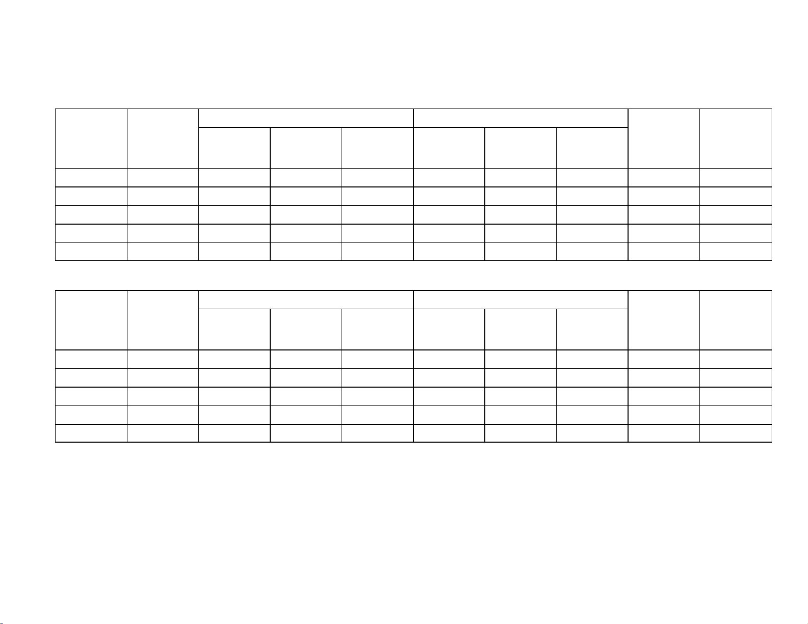
166240004
AVERAGE
AVERAGE
AVERAGE
AVERAGE
AVERAGE OPERATING CHARACTERISTICS
IRC630
IP Units
FREEZE CYCLE HARVEST CYCLE
38
AMBIENT
TEMP
_F
70 50 225 34 8:4 148 88 1:5 5.2 755
80 70 261 37 11:3 166 101 1.2 5.6 640
90 70 296 40 12:6 183 113 1:1 5.6 590
90 80 297 40 13:2 184 113 1:0 5.5 560
100 70 333 43 17:1 200 125 1:1 6.0 475
WATER
TEMP
_F
HEAD
PRESSURE
Psig
SUCTION
PRESSURE
Psig
CYCLE
TIME
Min:Sec
HEAD
PRESSURE
Psig
SUCTION
PRESSURE
Psig
CYCLE
TIME
Min:Sec
ICE
WEIGHT
lb/Cycle
SI Units
FREEZE CYCLE HARVEST CYCLE
AMBIENT
TEMP
_C
21 10 1551 234 8:4 1020 607 1:5 2.4 342
27 21 1800 255 11:3 1145 696 1:2 2.5 290
32 21 2041 276 12:6 1262 779 1:1 2.6 268
32 27 2048 276 13:2 1269 779 1:0 2.5 254
WATER
TEMP
_C
HEAD
PRESSURE
kPa
SUCTION
PRESSURE
kPa
CYCLE
TIME
Min:Sec
HEAD
PRESSURE
kPa
SUCTION
PRESSURE
kPa
CYCLE
TIME
Min:Sec
ICE
WEIGHT
kg/Cycle
ICE
WEIGHT
lb/Day
ICE
WEIGHT
kg/Day
12/1/94
Rev 3/4/96
38 21 2296 296 17:1 1379 862 1:1 2.7 215
Page 42

12/1/94
AVERAGE
AVERAGE
AVERAGE
AVERAGE
Rev 3/4/96
AVERAGE OPERATING CHARACTERISTICS
IAC830
IP Units
FREEZE CYCLE HARVEST CYCLE
39
AMBIENT
TEMP
_F
70 50 253 29 7:6 163 83 1:5 5.3 840
80 70 293 33 9:0 187 97 1.0 5.2 745
90 70 335 36 11:5 210 111 0:9 5.8 680
90 80 339 37 12:0 209 111 0:9 5.8 645
100 70 379 40 13:8 232 126 0:8 6.0 595
WATER
TEMP
_F
HEAD
PRESSURE
Psig
SUCTION
PRESSURE
Psig
CYCLE
TIME
Min:Sec
HEAD
PRESSURE
Psig
SUCTION
PRESSURE
Psig
CYCLE
TIME
Min:Sec
ICE
WEIGHT
lb/Cycle
SI Units
FREEZE CYCLE HARVEST CYCLE
AMBIENT
TEMP
_C
21 10 1744 200 7:6 1124 572 1:5 2.4 381
27 21 2020 228 9:0 1289 669 1:0 2.3 338
32 21 2310 248 11:5 1448 765 0:9 2.7 308
32 27 2337 255 12:0 1441 765 0:9 2.6 293
WATER
TEMP
_C
HEAD
PRESSURE
kPa
SUCTION
PRESSURE
kPa
CYCLE
TIME
Min:Sec
HEAD
PRESSURE
kPa
SUCTION
PRESSURE
kPa
CYCLE
TIME
Min:Sec
ICE
WEIGHT
kg/Cycle
ICE
WEIGHT
lb/Day
ICE
WEIGHT
kg/Day
166240004
38 21 2613 276 13:8 1600 869 0:8 2.7 270
Page 43

166240004
AVERAGE
AVERAGE
AVERAGE
AVERAGE
AVERAGE OPERATING CHARACTERISTICS
IWC830
IP Units
FREEZE CYCLE HARVEST CYCLE
40
AMBIENT
TEMP
_F
70 50 298 32 8:6 154 81 1:5 5.6 795
80 70 296 34 10:2 163 86 1.3 5.7 715
90 70 295 34 10:7 164 87 1:3 5.9 710
90 80 298 37 12:1 166 88 1:2 6.0 650
100 70 295 34 11:1 175 93 1:3 5.9 690
WATER
TEMP
_F
HEAD
PRESSURE
Psig
SUCTION
PRESSURE
Psig
CYCLE
TIME
Min:Sec
HEAD
PRESSURE
Psig
SUCTION
PRESSURE
Psig
CYCLE
TIME
Min:Sec
ICE
WEIGHT
lb/Cycle
SI Units
FREEZE CYCLE HARVEST CYCLE
AMBIENT
TEMP
_C
21 10 2055 221 8:6 1062 558 1:5 2.5 361
27 21 2041 234 10:2 1124 593 1:3 2.6 324
32 21 2034 234 10:7 1131 600 1:3 2.7 322
32 27 2055 255 12:1 1145 607 1:2 2.6 295
WATER
TEMP
_C
HEAD
PRESSURE
kPa
SUCTION
PRESSURE
kPa
CYCLE
TIME
Min:Sec
HEAD
PRESSURE
kPa
SUCTION
PRESSURE
kPa
CYCLE
TIME
Min:Sec
ICE
WEIGHT
kg/Cycle
ICE
WEIGHT
lb/Day
ICE
WEIGHT
kg/Day
12/1/94
Rev 3/4/96
38 21 2034 234 11:1 1207 641 1:3 2.7 313
Page 44
12/1/94
AVERAGE
AVERAGE
AVERAGE
AVERAGE
Rev 3/4/96
AVERAGE OPERATING CHARACTERISTICS
IRC830
IP Units
FREEZE CYCLE HARVEST CYCLE
41
AMBIENT
TEMP
_F
70 50 253 29 7:6 163 83 1:5 5.3 840
80 70 293 33 9:0 187 97 1.0 5.2 745
90 70 335 36 11:5 210 111 0:9 5.8 680
90 80 339 37 12:0 209 111 0:9 5.8 645
100 70 379 40 13:8 232 126 0:8 6.0 595
WATER
TEMP
_F
HEAD
PRESSURE
Psig
SUCTION
PRESSURE
Psig
CYCLE
TIME
Min:Sec
HEAD
PRESSURE
Psig
SUCTION
PRESSURE
Psig
CYCLE
TIME
Min:Sec
ICE
WEIGHT
lb/Cycle
SI Units
FREEZE CYCLE HARVEST CYCLE
AMBIENT
TEMP
_C
21 10 1744 200 7:6 1124 572 1:5 2.4 381
27 21 2020 228 9:0 1289 669 1:0 2.3 338
32 21 2310 248 11:5 1448 765 0:9 2.7 308
32 27 2337 255 12:0 1441 765 0:9 2.6 293
WATER
TEMP
_C
HEAD
PRESSURE
kPa
SUCTION
PRESSURE
kPa
CYCLE
TIME
Min:Sec
HEAD
PRESSURE
kPa
SUCTION
PRESSURE
kPa
CYCLE
TIME
Min:Sec
ICE
WEIGHT
kg/Cycle
ICE
WEIGHT
lb/Day
ICE
WEIGHT
kg/Day
166240004
38 21 2613 276 13:8 1600 869 0:8 2.7 270
Page 45

166240004
AVERAGE
AVERAGE
AVERAGE
AVERAGE
AVERAGE OPERATING CHARACTERISTICS
IAC1030
IP Units
FREEZE CYCLE HARVEST CYCLE
42
AMBIENT
TEMP
_F
70 50 240 33 13:5 164 75 1:7 11.6 1101
80 70 276 36 14:2 177 83 1.4 10.5 969
90 70 312 38 15:9 196 91 1:1 10.5 890
90 80 313 38 16:8 198 91 1:1 10.5 840
100 70 349 41 18:7 215 100 1:0 10.8 793
WATER
TEMP
_F
HEAD
PRESSURE
Psig
SUCTION
PRESSURE
Psig
CYCLE
TIME
Min:Sec
HEAD
PRESSURE
Psig
SUCTION
PRESSURE
Psig
CYCLE
TIME
Min:Sec
ICE
WEIGHT
lb/Cycle
SI Units
FREEZE CYCLE HARVEST CYCLE
AMBIENT
TEMP
_C
21 10 1655 228 13:5 1131 517 1:7 5.3 499
27 21 1903 248 14:2 1220 572 1:4 4.8 440
32 21 2151 262 15:9 1351 627 1:1 4.8 404
32 27 2158 262 16:8 1365 627 1:1 4.7 381
WATER
TEMP
_C
HEAD
PRESSURE
kPa
SUCTION
PRESSURE
kPa
CYCLE
TIME
Min:Sec
HEAD
PRESSURE
kPa
SUCTION
PRESSURE
kPa
CYCLE
TIME
Min:Sec
ICE
WEIGHT
kg/Cycle
ICE
WEIGHT
lb/Day
ICE
WEIGHT
kg/Day
12/1/94
Rev 3/4/96
38 21 2406 283 18:7 1482 689 1:0 4.9 360
Page 46

12/1/94
AVERAGE
AVERAGE
AVERAGE
AVERAGE
Rev 3/4/96
AVERAGE OPERATING CHARACTERISTICS
IWC1030
IP Units
FREEZE CYCLE HARVEST CYCLE
43
AMBIENT
TEMP
_F
70 50 296 34 13:0 155 73 1:8 10.7 1046
80 70 297 35 15:3 161 75 1.7 10.9 925
90 70 297 36 15:7 161 77 1:5 11.0 920
90 80 300 36 17:9 175 81 1:4 11.0 823
100 70 297 36 15:8 164 77 1:5 11.0 915
WATER
TEMP
_F
HEAD
PRESSURE
Psig
SUCTION
PRESSURE
Psig
CYCLE
TIME
Min:Sec
HEAD
PRESSURE
Psig
SUCTION
PRESSURE
Psig
CYCLE
TIME
Min:Sec
ICE
WEIGHT
lb/Cycle
SI Units
FREEZE CYCLE HARVEST CYCLE
AMBIENT
TEMP
_C
21 10 2041 234 13:0 1069 503 1:8 4.9 474
27 21 2048 241 15:3 1110 517 1:7 4.9 420
32 21 2048 248 15:7 1110 531 1:5 5.0 417
32 27 2068 248 17:9 1207 558 1:4 5.0 373
WATER
TEMP
_C
HEAD
PRESSURE
kPa
SUCTION
PRESSURE
kPa
CYCLE
TIME
Min:Sec
HEAD
PRESSURE
kPa
SUCTION
PRESSURE
kPa
CYCLE
TIME
Min:Sec
ICE
WEIGHT
kg/Cycle
ICE
WEIGHT
lb/Day
ICE
WEIGHT
kg/Day
166240004
38 21 2048 248 15:8 1131 531 1:5 5.0 415
Page 47

166240004
AVERAGE
AVERAGE
AVERAGE
AVERAGE
AVERAGE OPERATING CHARACTERISTICS
IRC1030
IP Units
FREEZE CYCLE HARVEST CYCLE
44
AMBIENT
TEMP
_F
70 50 240 33 13:5 164 75 1:7 11.6 1101
80 70 276 36 14:2 177 83 1.4 10.5 969
90 70 312 38 15:9 196 91 1:1 10.5 890
90 80 313 38 16:8 198 91 1:1 10.5 840
100 70 349 41 18:7 215 100 1:0 10.8 793
WATER
TEMP
_F
HEAD
PRESSURE
Psig
SUCTION
PRESSURE
Psig
CYCLE
TIME
Min:Sec
HEAD
PRESSURE
Psig
SUCTION
PRESSURE
Psig
CYCLE
TIME
Min:Sec
ICE
WEIGHT
lb/Cycle
SI Units
FREEZE CYCLE HARVEST CYCLE
AMBIENT
TEMP
_C
21 10 1655 228 13:5 1131 517 1:7 5.3 499
27 21 1903 248 14:2 1220 572 1:4 4.8 440
32 21 2151 262 15:9 1351 627 1:1 4.8 404
32 27 2158 262 16:8 1365 627 1:1 4.7 381
WATER
TEMP
_C
HEAD
PRESSURE
kPa
SUCTION
PRESSURE
kPa
CYCLE
TIME
Min:Sec
HEAD
PRESSURE
kPa
SUCTION
PRESSURE
kPa
CYCLE
TIME
Min:Sec
ICE
WEIGHT
kg/Cycle
ICE
WEIGHT
lb/Day
ICE
WEIGHT
kg/Day
12/1/94
Rev 3/4/96
38 21 2406 283 18:7 1482 689 1:0 4.9 360
Page 48

12/1/94
AVERAGE
AVERAGE
AVERAGE
AVERAGE
Rev 3/4/96
AVERAGE OPERATING CHARACTERISTICS
IAC1230
IP Units
FREEZE CYCLE HARVEST CYCLE
45
AMBIENT
TEMP
_F
70 50 231 30 8:8 175 75 1:5 8.9 1249
80 70 266 33 11:4 191 84 1.1 9.5 1090
90 70 296 35 13:6 211 95 1:0 10.1 1000
90 80 295 36 14:5 211 93 0:9 10.1 948
100 70 331 38 16:3 232 105 0:9 10.3 865
WATER
TEMP
_F
HEAD
PRESSURE
Psig
SUCTION
PRESSURE
Psig
CYCLE
TIME
Min:Sec
HEAD
PRESSURE
Psig
SUCTION
PRESSURE
Psig
CYCLE
TIME
Min:Sec
ICE
WEIGHT
lb/Cycle
SI Units
FREEZE CYCLE HARVEST CYCLE
AMBIENT
TEMP
_C
21 10 1593 207 8:8 1207 517 1:5 4.1 567
27 21 21834 228 11:4 1317 579 1:1 4.3 494
32 21 2041 241 13:6 1455 655 1:0 4.6 454
32 27 2034 248 14:5 1455 641 0:9 4.6 430
WATER
TEMP
_C
HEAD
PRESSURE
kPa
SUCTION
PRESSURE
kPa
CYCLE
TIME
Min:Sec
HEAD
PRESSURE
kPa
SUCTION
PRESSURE
kPa
CYCLE
TIME
Min:Sec
ICE
WEIGHT
kg/Cycle
ICE
WEIGHT
lb/Day
ICE
WEIGHT
kg/Day
166240004
38 21 2282 262 16:3 1600 724 0:9 4.7 392
Page 49

166240004
AVERAGE
AVERAGE
AVERAGE
AVERAGE
AVERAGE OPERATING CHARACTERISTICS
IWC1230
IP Units
FREEZE CYCLE HARVEST CYCLE
46
AMBIENT
TEMP
_F
70 50 336 30 10:1 187 73 1:4 9.8 1221
80 70 324 30 13:2 177 76 1.3 10.7 1065
90 70 330 33 14:0 180 76 1:3 10.9 1030
90 80 323 32 14:8 180 78 1:3 10.9 973
100 70 324 30 14:0 180 76 1:3 10.9 1025
WATER
TEMP
_F
HEAD
PRESSURE
Psig
SUCTION
PRESSURE
Psig
CYCLE
TIME
Min:Sec
HEAD
PRESSURE
Psig
SUCTION
PRESSURE
Psig
CYCLE
TIME
Min:Sec
ICE
WEIGHT
lb/Cycle
SI Units
FREEZE CYCLE HARVEST CYCLE
AMBIENT
TEMP
_C
21 10 2317 207 10:1 1289 503 1:4 4.4 554
27 21 2234 207 13:2 1220 524 1:3 4.9 483
32 21 2275 228 14:0 1241 524 1:3 5.0 467
32 27 2227 221 14:8 1241 538 1:3 4.9 441
WATER
TEMP
_C
HEAD
PRESSURE
kPa
SUCTION
PRESSURE
kPa
CYCLE
TIME
Min:Sec
HEAD
PRESSURE
kPa
SUCTION
PRESSURE
kPa
CYCLE
TIME
Min:Sec
ICE
WEIGHT
kg/Cycle
ICE
WEIGHT
lb/Day
ICE
WEIGHT
kg/Day
12/1/94
Rev 3/4/96
38 21 2234 207 14:0 1241 524 1:3 4.9 465
Page 50

12/1/94
AVERAGE
AVERAGE
AVERAGE
AVERAGE
Rev 3/4/96
AVERAGE OPERATING CHARACTERISTICS
IRC1230
IP Units
FREEZE CYCLE HARVEST CYCLE
47
AMBIENT
TEMP
_F
70 50 231 30 8:8 175 75 1:5 8.9 1249
80 70 266 33 11:4 191 84 1.1 9.5 1090
90 70 296 35 13:6 211 95 1:0 10.1 1000
90 80 295 36 14:5 211 93 0:9 10.1 948
100 70 331 38 16:3 232 105 0:9 10.3 865
WATER
TEMP
_F
HEAD
PRESSURE
Psig
SUCTION
PRESSURE
Psig
CYCLE
TIME
Min:Sec
HEAD
PRESSURE
Psig
SUCTION
PRESSURE
Psig
CYCLE
TIME
Min:Sec
ICE
WEIGHT
lb/Cycle
SI Units
FREEZE CYCLE HARVEST CYCLE
AMBIENT
TEMP
_C
21 10 1593 207 8:8 1207 517 1:5 4.1 567
27 21 1834 228 11:4 1317 579 1:1 4.3 494
32 21 2041 241 13:6 1455 655 1:0 4.6 454
32 27 2034 248 14:5 1455 641 0:9 4.6 430
WATER
TEMP
_C
HEAD
PRESSURE
kPa
SUCTION
PRESSURE
kPa
CYCLE
TIME
Min:Sec
HEAD
PRESSURE
kPa
SUCTION
PRESSURE
kPa
CYCLE
TIME
Min:Sec
ICE
WEIGHT
kg/Cycle
ICE
WEIGHT
lb/Day
ICE
WEIGHT
kg/Day
166240004
38 21 2282 262 16:3 1600 724 0:9 4.7 392
Page 51

166240004
AVERAGE
AVERAGE
AVERAGE
AVERAGE
AVERAGE OPERATING CHARACTERISTICS
IAC1448
IP Units
FREEZE CYCLE HARVEST CYCLE
48
AMBIENT
TEMP
_F
70 50 246 31 10:1 185 79 1:3 12.1 1525
80 70 280 34 11:8 201 88 1.3 12.3 1355
90 70 315 35 13:2 220 97 1:1 12.6 1275
90 80 317 37 13:7 222 98 1:1 12.4 1205
100 70 352 38 15:8 242 106 0:8 13.1 1140
WATER
TEMP
_F
HEAD
PRESSURE
Psig
SUCTION
PRESSURE
Psig
CYCLE
TIME
Min:Sec
HEAD
PRESSURE
Psig
SUCTION
PRESSURE
Psig
CYCLE
TIME
Min:Sec
ICE
WEIGHT
lb/Cycle
SI Units
FREEZE CYCLE HARVEST CYCLE
AMBIENT
TEMP
_C
21 10 1696 214 10:1 1276 545 1:3 5.5 692
27 21 1931 234 11:8 1386 607 1:3 5.6 615
32 21 2172 241 13:2 1517 669 1:1 5.7 578
32 27 2186 255 13:7 1531 676 1:1 5.6 547
WATER
TEMP
_C
HEAD
PRESSURE
kPa
SUCTION
PRESSURE
kPa
CYCLE
TIME
Min:Sec
HEAD
PRESSURE
kPa
SUCTION
PRESSURE
kPa
CYCLE
TIME
Min:Sec
ICE
WEIGHT
kg/Cycle
ICE
WEIGHT
lb/Day
ICE
WEIGHT
kg/Day
12/1/94
Rev 3/4/96
38 21 2427 262 15:8 1669 731 0:8 6.0 517
Page 52

12/1/94
AVERAGE
AVERAGE
AVERAGE
AVERAGE
Rev 3/4/96
AVERAGE OPERATING CHARACTERISTICS
IWC1448
IP Units
FREEZE CYCLE HARVEST CYCLE
49
AMBIENT
TEMP
_F
70 50 316 32 9:9 180 73 1:7 12.1 1505
80 70 318 35 11:9 188 77 1.4 12.7 1370
90 70 318 36 12:2 190 78 1:3 12.8 1360
90 80 317 37 13:0 194 80 1:3 12.6 1270
100 70 316 36 12:7 189 77 1:4 13.1 1335
WATER
TEMP
_F
HEAD
PRESSURE
Psig
SUCTION
PRESSURE
Psig
CYCLE
TIME
Min:Sec
HEAD
PRESSURE
Psig
SUCTION
PRESSURE
Psig
CYCLE
TIME
Min:Sec
ICE
WEIGHT
lb/Cycle
SI Units
FREEZE CYCLE HARVEST CYCLE
AMBIENT
TEMP
_C
21 10 2179 221 9:9 1241 503 1:7 5.5 683
27 21 2193 241 11:9 1296 531 1:4 5.8 621
32 21 2193 248 12:2 1310 538 1:3 5.8 617
32 27 2186 255 13:0 1338 552 1:3 5.7 576
WATER
TEMP
_C
HEAD
PRESSURE
kPa
SUCTION
PRESSURE
kPa
CYCLE
TIME
Min:Sec
HEAD
PRESSURE
kPa
SUCTION
PRESSURE
kPa
CYCLE
TIME
Min:Sec
ICE
WEIGHT
kg/Cycle
ICE
WEIGHT
lb/Day
ICE
WEIGHT
kg/Day
166240004
38 21 2179 248 12:7 1303 531 1:4 5.9 606
Page 53

166240004
AVERAGE
AVERAGE
AVERAGE
AVERAGE
AVERAGE OPERATING CHARACTERISTICS
IRC1448
IP Units
FREEZE CYCLE HARVEST CYCLE
50
AMBIENT
TEMP
_F
70 50 246 31 10:1 185 79 1:3 12.1 1535
80 70 280 34 11:8 201 88 1.3 12.4 1365
90 70 315 35 13:2 220 97 1:1 12.7 1285
90 80 317 37 13:7 222 98 1:1 12.5 1215
100 70 352 38 15:8 242 106 0:8 13.3 1150
WATER
TEMP
_F
HEAD
PRESSURE
Psig
SUCTION
PRESSURE
Psig
CYCLE
TIME
Min:Sec
HEAD
PRESSURE
Psig
SUCTION
PRESSURE
Psig
CYCLE
TIME
Min:Sec
ICE
WEIGHT
lb/Cycle
SI Units
FREEZE CYCLE HARVEST CYCLE
AMBIENT
TEMP
_C
21 10 1696 214 10:1 1276 545 1:3 5.5 696
27 21 1931 234 11:8 1386 607 1:3 5.6 619
32 21 2172 241 13:2 1517 669 1:1 5.8 583
32 27 2186 255 13:7 1531 676 1:1 5.7 551
WATER
TEMP
_C
HEAD
PRESSURE
kPa
SUCTION
PRESSURE
kPa
CYCLE
TIME
Min:Sec
HEAD
PRESSURE
kPa
SUCTION
PRESSURE
kPa
CYCLE
TIME
Min:Sec
ICE
WEIGHT
kg/Cycle
ICE
WEIGHT
lb/Day
ICE
WEIGHT
kg/Day
12/1/94
Rev 3/4/96
38 21 2427 262 15:8 1669 731 0:8 6.0 522
Page 54

TROUBLESHOOTING
IMPORTANT: Only qualified personnel should service internal components or electrical wiring.
Trouble Probable Cause Remedy
CUBER NOT OPERATING A. Power switch in center “OFF”
position.
CUBER NOT OPERATING,
INDICATOR LIGHTS “OFF”,
NO POWER TO CIRCUIT
BOARD
CUBER NOT OPERATING,
INDICATOR LIGHTS “OFF”,
POWER TO THE CIRCUIT
BOARD
A. Test power switch and leads. A. If defective, replace.
B. High pressure cut-out open.
(water cooled or remote
systems)
A. Magnet not in proximity switch
field.
B. No curtain movement. B. Adjust proximity switch.
C. Faulty proximity switch. C. Replace proximity switch.
A. Place switch in “ON” position.
B. Press manual reset.
Determine cause:
Water supply shut off; water
pressure too low; water valve
defective or out of adjustment;
water condenser dirty or
corroded; unit overcharged; water
inlet pressure too high. Replace
defective component as needed.
A. Water curtain drifting out of switch
range. Reduce clearance between
curtain and proximity switch.
COMPRESSOR DOES NOT
RUN, CIRCUIT BOARD
INDICATOR LIGHTS “ON”
12/1/94
Rev 3/4/96
D. Unit “OFF” due to bin full. D. Remove ice from curtain.
Eliminate curtain restriction.
A. Check contactor and leads. A. Replace if defective.
B. Compressor overload “open”. B. Permit overload to cool and reset
or replace.
C. Check compressor and start
components.
51
C. Replace as needed.
166240004
Page 55

Trouble Probable Cause Remedy
COMPRESSOR RUNS BUT
DOES NOT COOL, CIRCUIT
BOARD INDICATOR LIGHTS
“ON”
CUBER REMAINS IN THE
FREEZE CYCLE
CUBER REMAINS IN THE
HARVEST CYCLE
A. Low charge. A. Leak check – Recharge.
B. Hot gas solenoid leaking. B. Replace.
C. Defective expansion valve. C. Replace.
D. Inefficient compressor. D. Replace.
E. Internal by-pass open,
E. Permit pressures to equalize.
compressor noisy.
A. Check suction line thermistor
A. Tighten, reattach.
(sensor) lead wire connection
at the circuit board.
B. Evaporator thermistor shorted. B. Replace.
C. Check thermistor (1K ohm). C. Replace if out of range.
D. Ice bridge setting too low. D. Adjust per bridge adjustment
instructions.
E. Expansion valve failure (will
not pull down).
E. Tighten bulb, replace as needed.
See check-out procedure.
SUCTION LINE THERMISTOR
OPEN (STARTS IN HARVEST)
A. Loose connection at the circuit
A. Tighten or reconnect.
board.
B. Test thermistor. B. Replace if out of range.
PROXIMITY SWITCH LIGHT
“OUT”
C. Loose wire connection at
C. Tighten, reattach wire.
circuit board.
D. Proximity switch defective, see
D. Replace as needed.
check-out procedure.
E. Water curtain stuck, curtain
E. Check and adjust as needed.
frozen to ice on evaporator.
Curtain hung on water pan,
proximity switch out of range.
PROXIMITY SWITCH LIGHT “ON”
F. Circuit board failure. Check
F. Replace as needed.
voltage output.
G. Ice weight too light. G. Adjust bridge per Bridge
Adjustment instructions.
H. Potentiometer set too high. H. Adjust bridge per Bridge
Adjustment instructions.
166240004
I. Water curtain stuck, curtain
frozen to ice on evaporator.
Curtain hung on water pan,
proximity switch out of range.
52
I. Check and adjust as needed.
12/1/94
Rev 3/4/96
Page 56

Trouble Probable Cause Remedy
LONG FREEZE CYCLE
WATER FLOW ASSOCIATED
LONG FREEZE CYCLE
GENERAL
A. Float set too high. A. Adjust.
B. Float stuck. B. Clean or replace.
C. Flow control washer missing or
C. Replace or re-install.
upside down (number must be
facing up).
A. Water leaking around pan or
A. Adjust as needed.
curtain.
B. Dirty condenser or fan blade. B. Clean as required.
C. Louvers at condenser
C. Remove obstruction.
obstructed.
D. Ambient air or water
D. Advise customer.
temperature too high.
E. Condenser discharge air
E. Install condenser baffle.
re-circulating.
F. Low charge. F. Check for leak, correct, evacuate
and recharge.
G. Hot gas solenoid valve leaking
G. Replace.
(not seating).
H. Water regulator valve set too
high or stuck (water cooled
H. Adjust, clean or replace (setting to
be 300 to 310 PSI).
units only).
LONG HARVEST CYCLES A. Ice weight set too light. A. Adjust bridge per adjustment
instructions.
B. Unit not level. B. Level the unit.
C. Water curtain movement
C. Remove restriction.
restricted.
D. Low head pressure: ambient
too low.
E. Low head pressure; water
valve set too low (water cooled
D. Minimum ambient temperature
50_F (10_C).
E. Adjust water regulator valve or
replace (300 to 310 PSI).
units only) or leaking during
harvest.
F. Scale build-up on evaporator. F. Clean per instructions.
G. Hot gas solenoid valve not
G. Replace valve.
opening. Slow rise of low side
pressure.
H. Expansion valve leaking. H. Replace valve.
12/1/94
Rev 3/4/96
53
166240004
Page 57

Trouble Probable Cause Remedy
ICE WEIGHT LIGHT AT TOP
OF PLATE AND HEAVY AT
THE BOTTOM
NOTE: REVIEW DRAWING
ON PAGE 19 OF THIS
MANUAL FOR NORMAL ICE
SLAB.
A. Float stuck open. A. Replace the float valve.
B. Flow control washer missing
B. Replace or re-install as needed.
from the float or installed
upside-down (numbers must
be facing up).
C. Water flow rate over the
evaporator too fast.
D. Water leaking around curtain
C. Check position of distribution tube
(inner & outer).
D. Correct.
and pan; curtain frozen in the
ice.
E. Expansion valve flooding. E. Tighten and seal bulb. Replace
TXV if required.
F. Condenser air re-circulating. F. Install baffle.
G. Low charge. G. Leak check, evacuate & recharge.
H. Hot gas solenoid valve leaking. H. Replace.
I. Evaporator wall gasket torn or
I. Replace.
missing, allowing condenser
air to reach top of evaporator.
SOFT WHITE ICE OR WATER
PUMP NOT PUMPING
A. Distribution tube or water
system scaled.
A. Clean distribution system as
required.
B. Water temperature too cold. B. 50_F (10_C) minimum.
C. Inadequate water system;
C. Correct.
water pressure too low (below
20 PSI).
D. Inadequate water system; float
D. Replace.
plugged or damaged.
E. Distributor tubes – old style E. Replace with new style, 47 hole,
distributor tube. High flow tubes
require new style water curtains to
contain water.
166240004
54
12/1/94
Rev 3/4/96
Page 58

WH
UNIT
SWITCH
BL
BK
2
RH Evap.
Switc
h
N
S
(White Lead)
Condenser
Sensor
See note 1
Suction Line
Sensor
(Brown Lead)
To Stacked
Unit
(if required)
GR
CONTACTOR
BK
1
3
BR
Options
BL
D-13
YL
RH Evap.
YL
D-10
LH Evap.
Condenser
Plug
Suction
Plug
Test
Plug
Plug
Micro
Processor
Stacking
Cable
Plug
WH
CO
450 PSIG
BR
D-15
GR
D-14
GR
GR
D-12
Error
Adjustable
Ice
Thickness Pot.
RD
Water
Dump
Valve
Relay
Water
Pump
D-11
GR
D-6
GR
D-5
Manual
Harvest
Switch
BR
BK
M
BK
CONDENSATION
FAN (W/C ONLY)
MANUAL RESET
HIGH PRESSURE
CONTROL(W/C ONLY)
BL
YL
Hot Gas
Valve
Condenser
Fan
Transformer
3
7
5
3
1
BK
1
230V
Voltage
Selector
Switch
115V
COMPRESSOR
BR
WATER DUMP
SWITCH
2
8
6
4
2
RD
R
C
S
COMPRESSOR
BK
WH
BL
EXTERNAL
OVERLOAD
CURRENT
START RELAY
BL
HOT GAS
SOLENOID
RD
YL
WATER DUMP
VALVE
CONDENSER
FAN MOTOR
(A/C ONLY)
M
COMPRESSOR
START
CAPACITOR
243-292 mfd
115 VAC
OR
2
5
1
WH
WH
WH
BK
WH
WH
PUMP
CORD
WH
M
WATER PUMP
12/1/94
Rev 3/4/96
BL
NOTE 1: CONDENSER SENSOR USED ONLY ON A/C UNITS.
1.8K ohm RESISTOR USED ONLY ON W/C UNITS.
55
IAC 322 & IWC 322
IAC 330 & IWC 330
166240004
Page 59

POWER
CORD
BK
GR
CONTACTOR
BK
WH
WH
COMPRESSOR
START
CAPACITOR
BK
BR
COMPRESSOR
R
C
S
RD
YL
243-292 mfd
115 VAC
EXTERNAL
COMPRESSOR
M
OVERLOAD
OR
UNIT
SWITCH
BL
2
RH Evap.
Switch
N
S
(White Lead)
Condenser
Sensor
See note 1
Suction Line
Sensor
(Brown Lead)
To Stacked
Unit
(if required)
BR
BK
1
BL
CONDENSATION
FAN (W/C ONLY)
POTENTIAL
START RELAY
3
2
5
1
WH
MANUAL RESET
HIGH PRESSURE
BR
CO
450 PSIG
BR
CONTROL(W/C ONLY)
BL
BK
1
3
2
WATER DUMP
SWITCH
WATER DUMP
VALVE
WH
CONDENSER
WH
FAN MOTOR
M
(A/C ONLY)
BK
BK
PUMP
CORD
WATER PUMP
WH
WH
M
D-13
YL
RH Evap.
YL
D-10
LH Evap.
Condenser
Plug
Suction
Plug
Test
Plug
Options
Plug
Micro
Processor
Stacking
Cable
Plug
D-15
GR
D-14
GR
GR
D-12
Adjustable Ice
Thickness Pot.
Error
RD
Water
Dump
Valve
Relay
Water
Pump
D-11
GR
D-6
GR
D-5
Manual
Harvest
Switch
YL
Hot Gas
Valve
Condenser
Fan
Transformer
7
5
3
1
230V
Voltage
Selector
Switch
115V
BK
8
6
4
2
RD
WH
BL
HOT GAS
SOLENOID
BL
BL
NOTE 1: CONDENSER SENSOR USED ONLY ON A/C UNITS.
1.8K ohm RESISTOR USED ONLY ON W/C UNITS.
12/1/94
Rev 3/4/96
IACS 227 & IWCS 227 115 Volts 60 HZ
56
ILL339
166240004
Page 60

POWER
CORD
BK
RD
RD
SWITCH
BL
N
S
N
S
Condenser Sensor
See note 1
Suction Line
Sensor
(Brown Lead)
To Stacked
(if required)
RD
UNIT
RH Evap.
Switch
LH Evap.
Switch
(White Lead)
Unit
GR
BK
BR
BR
Test
Plug
Options
Stacking
Cable
Plug
CONTACTOR
RD
BL
450 PSIG
BR
D-15
GR
D-13
D-14
YL
GR
RH Evap.
GR
D-10
D-12
YL
LH Evap.
Condenser
Plug
Suction
Plug
RD
Error
Plug
Adjustable Ice
Thickness Pot.
Micro
Processor
BR
BK
M
BK
CONDENSATION FAN
(W/C ONLY)
HIGH PRESSURE CONTROL
CO
BL
YL
Water
Dump
Valve
Relay
Water
Pump
D-11
Hot Gas
GR
Valve
D-6
Condenser
GR
Fan
D-5
Transformer
Manual
Harvest
Switch
MANUAL RESET
(W/C ONLY)
BK
WATER DUMP
1
2
8
6
4
21
SWITCH
3
7
5
3
230V
Voltage
Selector
Switch
115V
RD
COMPRESSOR
R
C
S
EXTERNAL
COMPRESSOR
OVERLOAD
BK
RD
RD
HOT GAS
SOLENOID
BL
RD
RD
YL
WATER DUMP
CONDENSOR
FAN MOTOR
(A/C ONLY)
BL
COMPRESSOR
START
CAPACITOR
43-52 mfd 220 VAC
VALVE
M
WH
BK
WH
PUMP
CORD
WATER PUMP
WH
M
CURRENT
RELAY
S
M
RD
WH
WH
L
RD
12/1/94
Rev 3/4/96
BL
IACS227E60, IWCS227E60, 208/230V 60HZ
57
Artwork 50910
166240004
Page 61

WH
UNIT
SWITCH
BL
BK
2
RH Evap.
Switch
N
S
(White Lead)
Condenser
Sensor
See note 1
Suction Line
Sensor
(Brown Lead)
To Stacked
Unit
(if required)
GR
CONTACTOR
BK
1
3
BR
BL
D-13
YL
RH Evap.
YL
D-10
LH Evap.
Condenser
Plug
Suction
Plug
Test
Plug
Options
Plug
Micro
Processor
Stacking
Cable
Plug
WH
CO
450 PSIG
BR
D-15
GR
D-14
GR
GR
D-12
Adjustable Ice
Thickness Pot.
Error
RD
Water
Dump
Valve
Relay
Water
Pump
D-11
GR
D-6
GR
D-5
Manual
Harvest
Switch
BR
BK
M
BK
CONDENSATION
FAN (W/C ONLY)
MANUAL RESET
HIGH PRESSURE
CONTROL(W/C ONLY)
BL
YL
Hot Gas
Valve
Condenser
Fan
Transformer
3
7
5
3
1
BK
1
230V
Voltage
Selector
Switch
115V
COMPRESSOR
BR
WATER DUMP
SWITCH
2
8
6
4
2
C
BK
RD
BL
BL
R
S
EXTERNAL
COMPRESSOR
OVERLOAD
POTENTIAL
START RELAY
BL
WH
HOT GAS
SOLENOID
COMPRESSOR
RD
30 mfd
440 VAC
YL
WATER DUMP
VALVE
CONDENSER
FAN MOTOR
(A/C ONLY)
M
IAC 522 & IWC 522
IAC 530 & IWC 530
RUN
CAPACITOR
YL
2
5
1
WH
BK
RD
72-86 mfd
330 VAC
WH
PUMP
CORD
WATER PUMP
COMPRESSOR
START
CAPACITOR
OR
WH
WH
WH
WH
M
12/1/94
Rev 3/4/96
NOTE 1: CONDENSER SENSOR USED ONLY ON A/C UNITS.
1.8K ohm RESISTOR USED ONLY ON W/C UNITS.
58
166240004
Page 62

RD
BK
CRANKCASE
HEATER
(RC ONLY)
RD
RD
GR
BK
BK
BR
BR
LIQUID LINE
SOLENOID
(R/C ONLY)
CONTACTOR
RD
BL
450 PSIG
RD
BR
BK
BK
M
BK
CONDENSATION FAN
(W/C & R/C ONLY)
HIGH PRESSURE CONTROL
CO
BL
BK
BR
MANUAL RESET
(W/C & RC ONLY)
BK
RD
COMPRESSOR
R
C
S
EXTERNAL
COMPRESSOR
OVERLOAD
RD
RD
YL
POTENTIAL
START RELAY
WATER DUMP
COMPRESSOR
RUN
CAPACITOR
5
VALVE
YL
1
See note 2
35 mfd
370 VAC
2
WH
COMPRESSOR
START
CAPACITOR
RD
145-174 mfd
250 VAC
OR
RD
RD
UNIT
SWITCH
BL
RH Evap.
Switch
N
S
LH Evap.
Switch
N
S
(White Lead)
Condenser Sensor
See note 1
Suction Line
Sensor
(Brown Lead)
To Stacked
Unit
(if required)
D-13
YL
RH Evap.
D-10
YL
LH Evap.
Condenser
Plug
Suction
Plug
Test
Plug
Options
Plug
Micro
Processor
Stacking
Cable
Plug
BR
D-15
GR
D-14
GR
GR
D-12
Error
Adjustable Ice
Thickness Pot.
RD
Water
Dump
Valve
Relay
Water
Pump
D-11
GR
D-6
GR
D-5
Manual
Harvest
Switch
Hot Gas
Valve
Condenser
Fan
Transformer
YL
3
7
5
3
1
230V
Voltage
Selector
Switch
115V
WATER DUMP
1
SWITCH
2
8
6
4
2
RD
BK
RD
BL
BL
CONDENSOR
FAN MOTOR
(A/C ONLY)
BL
HOT GAS
SOLENOID
M
BK
WH
PUMP
CORD
WATER PUMP
IAC 830, IWC 830 & IRC 830
IAC 630, IWC 630 & IRC 630
WH
WH
M
12/1/94
Rev 3/4/96
NOTE 1: CONDENSER SENSOR USED ONLY ON A/C UNITS.
1.8K ohm RESISTER USED ONLY ON W/C & R/C UNITS.
NOTE 2: CAPACITORS USED ON 630 BRISTOL COMPRESSOR:
RUN CAP, 25mfd 440 VAC
START CAP. 161-193mfd 250 VAC
59
166240004
Page 63

RD
BK
RD
GR
CONTACTOR
BK
BK
LIQUID LINE
SOLENOID
(R/C ONLY)
RD
BR
BK
M
RD
BK
RD
COMPRESSOR
R
C
S
EXTERNAL
COMPRESSOR
OVERLOAD
RD
YL
RD
COMPRESSOR
RUN
CAPACITOR
SEE NOTE 2
40 mfd
370 VAC
YL
COMPRESSOR
START
CAPACITOR
RD
189-227 mfd
330 VAC
RD
OR
CRANKCASE
HEATER
(RC ONLY)
BK
BL
BK
BK
CONDENSATION
FAN (W/C & R/C)
MANUAL RESET
HIGH PRESSURE
CONTROL(W/C & R\C)
CO
RD
SWITCH
BL
RH Evap.
N
S
LH Evap.
N
S
(White Lead)
Condenser Sensor
See note 1
Suction Line
Sensor
(Brown Lead)
To Stacked
(if required)
Switch
Switch
Unit
UNIT
BR
D-13
YL
RH Evap.
D-10
YL
LH Evap.
Condenser
Plug
Suction
Plug
Test
Plug
Options
Plug
Micro
Processor
Stacking
Cable
Plug
450 PSIG
D-15
GR
D-14
GR
GR
D-12
Error
Adjustable Ice
Thickness Pot.
D-11
RD
Water
Dump
Relay
Pump
D-6
Valve
Water
GR
GR
D-5
Manual
Harvest
Switch
BR
Hot Gas
Condenser
BL
Valve
Fan
Transformer
YL
BK
3
7
5
3
230V
Voltage
Selector
Switch
115V
1
2
8
6
4
21
NOTE 1: CONDENSER SENSOR USED ONLY ON A/C UNITS.
1.8K ohm RESISTOR USED ONLY ON W/C & R/C UNITS.
BR
WATER DUMP
SWITCH
BK
RD
RD
BL
BL
POTENTIAL
START RELAY
WATER DUMP
M
M
BL
HOT GAS
SOLENOID
2
5
1
RD
VALVE
WH
CONDENSER
FAN MOTORS
(A/C ONLY)
BK
BK
WH
WH
WH
PUMP
CORD
M
WATER PUMP
IAC 1230, IWC 1230 & IRC 1230
IAC 1030, IWC 1030 & IRC 1030
12/1/94
Rev 3/4/96
2: CAPACITORS USED ON 1030 COMPRESSOR
RUN CAP. 37MFD 370V
START CAP. 145 - 174 MFD 250V
60
166240004
Page 64

RD
UNIT
SWITCH
RD
RD
GR
CONTACTOR
BK
BK
BR
LIQUID LINE
SOLENOID
(R/C ONLY)
RD
BL
BK
RD
BR
M
CONDENSATION
FAN (W/C & R/C)
BK
BK
CRANKCASE HEATER
(A/C & R/C ONLY)
BK
BK
BK
RD
COMPRESSOR
BR
RD
R
C
S
EXTERNAL
COMPRESSOR
OVERLOAD
POTENTIAL
START RELAY
WATER DUMP
VALVE
COMPRESSOR
RUN
CAPACITOR
RD
YL
YL
2
5
1
WH
RD
40 mfd
440 VAC
COMPRESSOR
START
CAPACITOR
189-227 mfd
330 VAC
RD
OR
RD
BL
BR
RH Evap.
Switch
N
S
LH Evap.
Switch
N
S
(White Lead)
Condenser Sensor
See note 1
Suction Line
Sensor
(Brown Lead)
To Stacked
Unit
(if required)
CO
450 PSIG
MANUAL RESET
HIGH PRESSURE
CONTROL(W/C & R/C)
BR
D-15
GR
D-13
D-14
YL
GR
RH Evap.
GR
D-12
YL
D-10
LH Evap.
Condenser
Plug
Suction
Plug
Test
Plug
Options
Plug
Micro
Processor
Stacking
Cable
Plug
RD
Error
Adjustable Ice
Thickness Pot.
D-11
D-6
Water
Dump
Valve
Relay
Water
Pump
GR
GR
D-5
Manual
Harvest
Switch
BL
Hot Gas
Valve
Condenser
Fan
Transformer
3
YL
7
5
3
230V
Voltage
Selector
Switch
115V
WATER DUMP
1
SWITCH
2
8
6
4
21
BK
RD
BL
BL
BK
CONDENSER
FAN MOTOR
(A/C ONLY)
BL
RD
HOT GAS
SOLENOID
M
WH
WH
WH
PUMP
CORD
M
WATER PUMP
IAC 1448, IWC 1448 & IRC 1448
WH
12/1/94
Rev 3/4/96
NOTE 1: CONDENSER SENSOR USED ONLY ON A/C UNITS.
1.8K ohm RESISTOR USED ONLY ON W/C & R/C UNITS.
61
166240004
Page 65

BK
M
CAPACITOR
2 mfd 440 VAC
RED
COLORED
BAND
BK
HEAT SHRINK
TAPE
GR
FAN CYCLING
SWITCH
CONDENSER
FAN MOTOR
HEAT SHRINK TAPE
BK
HEAT SHRINK TAPE
12/1/94
Rev 3/4/96
RD
CR800, CR1200, & CR1400 REMOTE CONDENSERS
208/230 VOLTS 60 HZ
62
GR
166240004
Page 66

12/1/94
Rev 3/4/96
AIR COOLED CONDENSER
FAN BLADES
WATER
DUMP VALVE
63
WATER
FLOAT
VALV E
WATER PUMP
EVAPORATOR
THERMOSTATIC
EXPANSION VALVE
HOT GAS
SOLENOID
VALV E
S
HIGH SIDE
SERVICE
VALV E
FAN MOTOR
HEAT EXCHANGER
FILTER/DRIER
LOW SIDE
SERVICE
VALV E
166240004
REFRIGERATION AND WATER SYSTEMS
MODELS IAC227, IAC322, IAC330, IAC522, AND IAC530
MODELS IAC630, AND IAC830
MODEL IWCS227
COMPRESSOR
Page 67

166240004
AIR COOLED CONDENSER
FAN BLADES
WATER
DUMP VALVE
WATER PUMP
64
WATER
FLOAT VALVE
EVAPORATOR
HOT GAS
SOLENOID VALVE
EVAPORATOR
THERMOSTATIC
EXPANSION
VALV E
THERMOSTATIC
EXPANSION
VALV E
FAN MOTOR
HEAT EXCHANGER
HIGH SIDE
SERVICE
VALV E
FILTER/DRIER
LOW SIDE
SERVICE
VALV E
COMPRESSOR
12/1/94
Rev 3/4/96
Refrigeration and water system
Models IAC1030, IAC1230, and IAC1448
August 3, 1994
Page 68

12/1/94
Rev 3/4/96
WATER REGULATING
VALV E
WATER-COOLED CONDENSER
WATER INLET
WATER
DUMP VALVE
65
WATER
S
FLOAT
VALV E
WATER PUMP
EVAPORATOR
Refrigeration and Water Systems
Models IWC322, IWC330, IWC522, and IWC530
Models IWC603, and IWC830
Model IWCS227
August 3, 1994
THERMOSTATIC
EXPANSION VALVE
HOT GAS
SOLENOID
VALV E
S
HIGH SIDE
SERVICE
VALV E
HEAT EXCHANGER
PRESSURE SWITCH
LOW SIDE
SERVICE
VALV E
COMPRESSOR
FILTER/DRIER
166240004
Page 69

166240004
WATER REGULATING
VALV E
66
S
WATER
DUMP VALVE
WATER PUMP
WATER
FLOAT
VAVLE
EVAPORATOR
HOT GAS
SOLENOID
VALV E
S
EVAPORATOR
THERMOSTATIC
EXPANSION VALVE
THERMOSTATIC
EXPANSION VALVE
WATER INLET
HEAT EXCHANGER
HIGH SIDE
SERVICE
VALV E
LOW SIDE
SERVICE
VALV E
W
WATER-COOLED CONDENSER
FILTER/DRIER
PRESSURE
SWITCH
COMPRESSOR
12/1/94
Rev 3/4/96
REFRIGERATION AND WATER SYSTEM
MODELS IWC1030, IWC1230 AND 1WC1448
AUGUST 3, 1994
Page 70

12/1/94
Rev 3/4/96
FAN BLADES
PRESSURE SWITCH
HEAD
PRESSURE
CONTROL
67
S
WATER
DUMP VALVE
WATER PUMP
WATER
FLOAT
VALV E
EVAPORATOR
HOT GAS
SOLENOID
VALV E
THERMOSTATIC
EXPANSION VALVE
S
FAN MOTOR
LIQUID SOLENOID
VALV E
HEAT EXCHANGER
HIGH SIDE
SERVICE
VALV E
REMOTE CONDENSER
FILTER/DRIER
S
PRESSURE SWITCH
LOW SIDE
SERVICE
VALV E
COMPRESSOR
COUPLINGS
VALVES
RECEIVER
SERVICE VALVE
CHECK
VALV E
166240004
REFRIGERATION AND WATER SYSTEMS
MODELS IRC630 AND IRC830
AUGUST 3, 1994
Page 71

166240004
FAN BLADES
PRESSURE SWITCH
HEAD
PRESSURE
CONTROL
68
WATER
DUMP
VALV E
WATER PUMP
WATER
FLOAT
VALV E
EVAPORATOR
HOT GAS
SOLENOID
VALV E
EVAPORATOR
THERMOSTATIC
EXPANSION VALVE
THERMOSTATIC
EXPANSION VALVE
FAN MOTOR
LIQUID SOLENOID
VALV E
HEAT EXCHANGER
HIGH SIDE
SERVICE
VALV E
REMOTE CONDENSER
PRESSURE SWITCH
LOW SIDE
SERVICE
VALV E
COMPRESSOR
FILTER/DRIER
CHECK
VALV E
COUPLINGS
VALVES
RECEIVER
SERVICE VALVE
12/1/94
Rev 3/4/96
REFRIGERATION AND WATER SYSTEM
MODELS IRC1030, IRC1230 AND IRD1448
AUGUST 3, 1994
Page 72

12/1/94
Rev 3/4/96
FAN BLADES
PRESSURE SWITCH
HEAD PRESSURE
CONTROL
FAN MOTOR
COUPLINGS
VALVES
69
166240004
REMOTE CONDENSER
MODELS CR800, CR1200, AND CR1400
AUGUST 5, 1994
Page 73

“I” Series “Remote”
Ice Machine
166240004
70
12/1/94
Rev 3/4/96
Page 74

INSTALLATION INSTRUCTIONS REMOTE CONDENSERS
UNIT
LEG
1/4-20 SCREW
LEG
BRACE
1. Follow the standard installation instructions supplied with cuber. Do not hook cuber into the power source
until the remote condenser and line set installation is complete.
2. Assembly of remote condenser (see drawing):
A. Assemble legs to base panel. Install leg supports on legs.
B. Locate the remote condenser in a well–ventilated area on the roof away from other refrigeration equip-
ment’s condenser discharge air flow.
C. Use the mounting holes provided to secure the remote condenser to the roof. Seal over heads of bolts
or fasteners with tar or pitch to prevent entrance of moisture.
REMOTE CONDENSER
LEG
LEG SUPPORT
3. Remote condenser electrical hook-up:
A. Connect remote condenser to a power source (208/230VAC, 60 HZ) separate from the cuber. An ex-
ternal disconnect switch must be used.
B. Make sure the electrical connections follow all local and
national codes.
C. DO NOT turn condenser on until cuber install and refrigerant line connections are complete!
D. Never wire condenser into cuber section. The condenser is an independent electrical connection.
E. Fan motor will not start until pressure rises to 205 PSIG [14.07 Bars] closing fan cycling switch.
12/1/94
Rev 3/4/96
71
166240004
Page 75

F. The condenser fan may cycle off during the harvest cycle – this would be normal.
NOTE: Installing an IMI Cornelius remote cuber with other than an IMI Cornelius remote condenser
and line set may be reason to void the cuber warranty.
LIQUID
REFRIGERANT
LINE
DISCHARGE
LINE
CORRECT
4. Each condenser and cuber is connected with two (2) *pre-charged lines.
A. The pre-charged lines are ordered separately from the condenser to suit each individual application.
B. The pre-charged line lengths are 20 feet [6.096 meters], 35 feet [10.66 meters] and 55 feet [16.76 me-
ters].
NOTE (Pre-charged is defined as a vapor holding charge – not a portion of the system charge.)
5. Installation of line kits (see drawing). Remove the tubing from the carton. Carefully uncoil the lines so the
tubing doesn’t become kinked, and route lines to cuber and condenser.
6. Keep line-set as short as possible. Place a 3-foot service loop behind cuber to allow for rear service
should it ever be required.
166240004
72
12/1/94
Rev 3/4/96
Page 76

REMOTE CONDENSER LOCATION
1. Physical Line-Set Length: 55 Ft. Maximum [16.764 meters]
The ice machine compressor must have the proper oil return. Line-set rises, drop, or horizontal runs greater than the maximum distance allowed will exceed the compressor start-up and pumping design limits, and
will result in poor oil return to the compressor.
Line-Set Rise: 35 Ft. Maximum [10.66 meters]
Line-Set Drop: 15 Ft. Maximum [4.57 meters]
2. Calculated Line-Set Distance: 100 Ft. [30.48 meters]
To prevent the combination of rises, drops and horizontal runs exceeding the compressor start-up and
pumping design limit, the following calculations should be made:
NOTE: Max. line–set for IMI Cornelius cubers is 55 ft. Do not confuse line length with calculated line
distance
B
A
B
A - (RISE) CONDENSER HIGHER THAN EVAP.
MAX. 35 FT.
B - LINE LENGTH 15 FT.: EXAMPLE
B - LINE LENGTH 35 FT.: EXAMPLE
C - (DROP) CONDENSER LOWER THAN EVAP. 15 FT.: MAX.
Maximum Line-Set Distance Formula
A. Measured rise x 1.7= Calculated Rise 35 ft. Max) [10.66 meters]
B. Measured drop x 6.6= Calculated Drop 15 ft. Max) [4.57 meters]
C. Measured Horizontal Distance = actual measurement.
D. Total Calculated Distance (A+B+C)=Total Calculated Distance (100 ft. Max.) [30.48 meters]
Examples:
a. Insert measured rise (R) into the formula and multiply it by 1.7 to get a calculated rise.
example: A condenser located 15 ft. [4.572 meters] above the ice machine has a 25.5 ft. [8.874
meters] calculated total (15 ft. x 1.7 = 25.5).
H
AIR
FLOW
R
C
12/1/94
Rev 3/4/96
b. Insert measured drop (D) into formula and multiply by 6.6 to get a calculated drop.
example: A condenser located 8 ft. [2.438 meters] below the ice machine has a 52.8 ft. [16.093
meters] calculated total (8 ft. x 6.6 = 52.8 ft.).
73
166240004
Page 77

COMBINATION OF
DROP(S)
WITH HORIZONTAL
H
D
AIR
FLOW
c. Insert measured horizontal distance into formula. No calculation is necessary. (6 ft.) [1.828 me-
ters].
d. Add the calculated rise, calculated drop, and horizontal distance together to get the total calcu-
lated distance (25.5 + 52.8 + 6) equals 84.3 ft. [25.694 meters]. If 100 ft. [30.48 meters] total calculated distance is exceeded, the condenser must be moved to a new location which permits
proper equipment operation.
COMBINATION OF RISE AND
DROP(S)WITH HORIZONTAL
H
R
D
AIR
FLOW
CAUTION: If a line-set rise is followed by a line-set drop, a second line-set rise cannot be
made. Or If a line-set drop is followed by a line-set rise, a second line-set drop cannot be
made.
3. Lengthening or Reducing the Line-Set Lengths
In most cases, by routing the line-set properly, shortening will not be necessary (refer to illustration). However, when shortening or lengthening is required, do so before connecting the line-set to the ice machine or
the remote condenser. This prevents the loss of refrigerant from the ice machine or the condenser.
The quick connect fittings on the line-sets are equipped with Schrader Valves. Use these valves to recover
any vapor charge from the line-set. When lengthening or shortening lines, apply good refrigeration practices and insulate new tubing. Do not change the tube sizes. Evacuate the lines and place approximately 5
oz. of
vapor refrigerant charge in each line.
SCHRADER
VALV E
PARENT
METAL
SEAL
INTERMEDIATE
SEAL
4. Connection of Line-Set
A. Remove the plastic caps from the line-set, the condenser, and the ice machine.
B. Apply refrigeration oil to the threads on the quick connect couplers before connecting them to the con-
denser.
C. Carefully thread the female fitting onto the condenser or ice machine by hand.
D. Using the proper size wrench, tighten the couplings until they bottom out. Turn an additional 1/4 turn
to ensure proper brass-to-brass seating.
166240004
74
12/1/94
Rev 3/4/96
Page 78

E. Check all fittings for leaks.
5. Final Installation:
A. Remove grill from the right-hand side panel of cuber.
B. Turn service port on receiver tank to open position releasing refrigerant to the balance of the system.
C. Leak check line-set connections at cuber and condenser.
D. Replace grill.
E. Connect cuber to power source.
F. Make sure electrical connections follow all local and national codes.
6. Start Up:
A. Use standard procedures from cuber installation instructions.
B. After the cuber is running, check the remote condenser and verify that the condenser fan is running.
CAUTION: Once the refrigerant lines are connected, the seal is broken in the fittings. If the
lines are removed or loosened from the cuber or remote condenser, the refrigerant charge
will be discharged to the atmosphere. DISCHARGING TO THE ATMOSPHERE IS IN
VIOLATION OF THE CLEAN AIR ACT OF JULY, 1992.
12/1/94
Rev 3/4/96
75
166240004
Page 79

ICE CUBER SPECIFICATION
MODEL IRC630 IRC830 IRC1230 IRC1448
UNIT
Volts 208/230 + 10%, –5% 208/230 +10%, –5% 208/230 +10%, –5% 208/230 +10%, –5%
Phase 1 1 1 1
Hertz 60 60 60 60
No. Wires 2+ground 2+ground 2+ground 2+ground
MIN. CIRCUIT
Amps 20 20 20 25
MAX FUSE SIZE (HVAC CIRCUIT BREAKER REQUIRED)
Amps 20 20 20 25
REFRIGERANT
Type R404a(HP62) R404a(HP62) R404a(HP62) R404a(HP 62)
Weight (oz) 170 170 210 250
Weight (g) 4820 4820 5954 7088
COMPRESSOR
Volts 230 230 230 230
Phase 1 1 1 1
Hertz 60 60 60 60
LRA 69 61 96 95.6
RLA 8.8 12.5 13.5 23.9
AIR CIRCULATION FAN MOTOR
Volts 230 230 230 230
Phase 1 1 1 1
Hertz 60 60 60 60
Amps Running 0.36 0.36 0.36 0.36
Watts 6 6 6 6
WATER PUMP
Volts 230 230 230 230
Phase 1 1 1 1
Hertz 60 60 60 60
Amps Running 0.5 0.5 0.5 0.5
HP 1/30 1/30 1/30 1/30
REMOTE CONDENSER SPECIFICATION
MODEL CR800 CR1200 CR1400
Volts 230 230 230
Phase 1 1 1
Hertz 60 60 60
Amps 1.0 1.0 1.0
Output, HP 1/6 1/6 1/6
Max. fuse size, Amps (HVAC circuit breaker
required)
166240004
20 20 20
76
12/1/94
Rev 3/4/96
Page 80

HEAD PRESSURE CONTROL [HEADMASTER]
discharge
above 70°F
normal
receiver
discharge
condenser
condenser
below 70°F by-pass
receiver
The Cornelius “I” series remote systems use an Alco Head Pressure Control, normally referred to as a headmaster. This control is mounted in the remote condenser with a fan cycling control switch. Using both these
controls gives the system positive operation under a wide range of condensing temperatures.
The cycling control starts the fan at 270 PSI and stops it at 205 PSI allowing a positive efficient operation at the
high temperature operating ranges.
The headmaster controls the operation when the condensing temperature drops below 70°F. The “I” series refrigerant charge is HP - 62 [R - 404A] and the headmaster dome charge setting is 200 PSI of nitrogen pressure
making it stable under the low temperature operating range down to - 20°F.
The normal flow pattern through the headmaster is from the condenser port to the receiver port. When this flow
pattern is unable to maintain a receiver outlet pressure equal to or above the dome pressure setting of the
valve, the dome pressure will force the valve portage to change closing the condenser port and opening the bypass port from the compressor discharge line. This allows the high pressure vapor from the discharge port to
“buck” the receiver pressure back up. With the condenser port closed, the refrigerant is backed up in the condenser, basically reducing the condenser size, assisting in maintaining the discharge portage flow and increasing the head pressure.
Remember, sense of touch to the lines of the headmaster will determine the flow path the headmaster is in,
condenser to receive, or bypass to receiver.
High side gauge installed at the receiver outlet valve will determine if the headmaster is functioning to maintain
the proper operating pressure.
In the event the control appears to be “stuck in bypass”, the pressure drop across the headmaster must be
measured. With a gauge installed at the receiver outlet valve and the high side service valve, the pressure difference at these two points must be less than the 15 PSI. The three most common causes of an excessive
pressure drop are shortage of refrigerant, kinked remote lines, and excessive line length.
Eliminate refrigerant shortage first. Add refrigerant in two-pound increments (not to exceed six pounds) to
determine if it corrects the pressure drop. If pressure drop is not corrected, inspect line set for sharp bends or
kinks and correct as required. If adding refrigerant does not correct continued (bypass) condition and line set is
not damaged, replace headmaster.
12/1/94
Rev 3/4/96
77
166240004
Page 81

REMOTE SYSTEM EVACUATION/RE-CHARGE
All field repairs to the sealed system must start with a total discharge of the system following the requirements
of the Clean Air Act of July, 1992.
Proper evacuation of the total remote system will require a three (3) point hook-up of your manifold and hose
set, (see drawing):
Point #1 - Cuber receiver outlet valve
Point #2 - Cuber high side service valve
Point #3 - Cuber low side service valve
Evacuation:
1. With cuber power supply turned “OFF” disconnect and insulate all 3 compressor leads at the compressor.
Turn power supply on, place power switch in the “on” position. This will energize (open) the Liquid Line solenoid allowing evacuation of the Liquid Line between the solenoid and the expansion valve(s).
2. Evacuate system to 200/250 microns or less. At this point, there should be a holding test of five(5) minutes.
You may expect a slight loss of vacuum as normal. A rapid rise to normal atmospheric pressure indicates
moisture still present in the system. On a “wet” system, it will prove beneficial to use heat lamps to warm
the compressor dome and evaporator surface during evacuation.
3. Turn cuber power switch OFF. Reconnect compressor leads.
4. *After proper evacuation hold test has been performed, the refrigerant charge should be “dumped” into the
receiver until the pressure equalizes, stopping the flow. Do not try to throttle the refrigerant flow. Doing so
will allow system pressure to balance too soon. The high-side service valve should be closed and the balance of the charge fed slowly through the suction side service valve with the compressor operational. Control the feed rate at no faster than four (4) ounces [113.g] per minute to ensure the compressor oil does not
become too saturated with refrigerant resulting in a loss of compressor lubrication.
5. All refrigerant re-charging must be weighed into the system, utilizing an electronic charging scale. DO NOT
attempt to recharge the system by sight glass, system pressure, amperage, frost line or sweat patterns.
6. Always leak check entire system after recharge.
OPEN
RECEIVER
OPEN
RECEIVER
OUTLET
VA LV E
CAUTION: Before programming the electronic scales to “dump” the charge, de-energize
the liquid line solenoid, close the shut-off valve on vacuum pump and low side of the
manifold set.
EVACUATION
MANIFOLD SET
OPEN
OPEN
CHARGING
OPEN
CYLINDER
HIGH SIDE
SERVICE
VA LV E
LOW
SIDE
SERVICE
VA LV E
CLOSED
1ST STAGE CHARGING
OPEN
RECEIVER
OPEN
RECEIVER
OUTLET
VA LV E
CLOSED
MANIFOLD SET
CLOSED
CLOSED
HIGH SIDE
SERVICE
VA LV E
LOW
SIDE
SERVICE
VA LV E
OPEN
CHARGING
CYLINDER
CLOSED
2ND STAGE CHARGING
COMPRESSOR OPERATING
CLOSED
RECEIVER
RECEIVER
OUTLET
VA LV E
CLOSED
MANIFOLD SET
OPEN
CLOSED
CHARGING
CYLINDER
HIGH SIDE
SERVICE
SERVICE
VA LV E
OPEN
VA LV E
LOW
SIDE
VACUUM
PUMP
166240004
CLOSED
ELECTRONIC
SCALE
VACUUM
PUMP
78
OPEN
ELECTRONIC
SCALE
VACUUM
PUMP
OPEN
ELECTRONIC
SCALE
12/1/94
Rev 3/4/96
Page 82

THIS PAGE LEFT BLANK INTENTIONALLY
79 166240004
Page 83

IMI CORNELIUS INC.
CORPORATE HEADQUARTERS:
One Cornelius Place
Anoka, Minnesota 55303-6234
(763) 421-6120
(800) 238-3600
166240004
80
12/1/94
Rev 3/4/96
 Loading...