

Cornelius Granita Training Manual
ICE PEAK
Granita
Training Manual
®
Release Date: June 30, 2003
Publication Number: TP01057
Revision Date: NA
Revision: A
Visit the IMI Cornelius web site at www.cornelius.com
Distributed By:
Commercial Refrigeration Service, Inc.
http://WWW.IceCubes.NET
http://WWW.JetsprayParts.COM
(623) 869-8881
(866) 423-6253
for all your Literature needs.

ICE PEAK TRAINING MANUAL
The products, technical information, and instructions contained in this manual are subject
to change without notice. These instructions are not intended to cover all details or variations of the equipment, nor to provide for every possible contingency in the installation,
operation or maintenance of this equipment. This manual assumes that the person(s)
working on the equipment have been trained and are skilled in working with electrical,
plumbing, pneumatic, and mechanical equipment. It is assumed that appropriate safety
precautions are taken and that all local safety and construction requirements are being
met, in addition to the information contained in this manual.
To inquire about current revisions of this and other documentation or for assistance with
any Cornelius product contact:
IMI Cornelius Inc.
Corporate Headquarters
One Cornelius Place
Anoka, MN 55303-6234
U.S.A.
tech.service@cornelius.com
In the U.S.A.:
phone:763-421-6120
800-238-3600
FAX:800-535-4231
Trademarks and Copyrights:
Aurora, Cornelius, Decade, Hydro Boost, Sitco, Spirit, UF-1, Vanguard, Venture, Olympus,
and Vista are registered trademarks of IMI Cornelius Inc.
Optifill trademark is pending.
This document contains proprietary information and it may not be
reproduced in any way without permission from Cornelius.
Printed in U.S.A.
Copyright © 2003, All Rights Reserved, IMI Cornelius Inc.
Internet:
www.cornelius.com
Email:
Outside the U.S.A.:
phone:763-421-6120
FAX:763-422-3297
Distributed By:
Commercial Refrigeration Service, Inc.
http://WWW.IceCubes.NET
http://WWW.JetsprayParts.COM
(623) 869-8881
(866) 423-6253

Introduction 1
Preview Questions 1
Key Things To Know / Do 1
Overview 3
Product Description 3
Attractive Appearance 3
Merchandising 3
Multi-Cooling System 3
Mixing System 3
Controls 3
Option Section 4
Electronic Control Board 4
Advanced Features 4
Switch Control Board 4
Bowl Temperature 4
Over Temperature Sensor 5
Setting Defrost, Rocker Switch Models 6
Found on the Back of the Front Access Panel 6
High Pressure Cut Out Switch 7
Optional Accessories 8
Security Kit Installation 8
Installing Locking Clip 8
Auto Fill 9
Installation and Operation 9
Electrical Diagram Black Box Auto Fill 10
10
11
Mounting 11
Inlet Conditions 11
Outlet Lines to the Dispenser 12
Start-up Procedure 12
Ice Peak Training Manual
TABLE OF CONTENTS
System Details 13
Water Quality 13
Mechanical 13
Dispensing Product 13
Consistency Adjustment 14
Cleaning and Sanitizing Procedures 15
Daily Cleaning 15
Maintenance 19
Removing and cleaning the filter (Weekly) 19
Cleaning the Condenser (Monthly) 19
Replacing the Light Bulbs (As Needed) 20
Seal Maintenance 22
Bell Shaped Seal 22
Spindle Bushing Seal 22
Bowl Gasket (located at rear of bowl) 23
O-Ring Maintenance 23
© 2003, IMI Cornelius Inc. - i - Publication Number: TP01057

Ice Peak Training Manual
Refrigeration Diagram 24
Electrical Diagram 25
Troubleshooting 27
Appendix A - Component Replacement 33
Gear Motor Removal 33
Viscosity Switch Removal 36
Condenser Filter Replacement 37
Transformer Removal 38
Service Control Board 39
Review 41
Publication Number: TP01057 - ii - © 2003, IMI Cornelius Inc.

INTRODUCTION
PREVIEW QUESTIONS
Check your current knowledge by taking a few minutes to answer the following questions:
1. It is OK to fill the bowl with water and dry ingredients for mixing? True or False
2. The Ice Peak units do not need to be defrosted? True or False
3. Bowls and other parts are dishwasher safe? True or False
4. It is OK to run diet drinks in the Ice Peak units? True or False
5. It is OK for the airflow to be blocked on one side of the unit? True or False
KEY THINGS TO KNOW / DO
• Work safely! Always unplug the power before servicing the unit.
• Read the installation manual before installing this equipment.
• Make sure that there is adequate airflow on all sides and the rear of the equipment.
• Always premix the product before putting it into the bowl.
• Do not wait for the filter alarm to sound before cleaning the condenser, it should be done monthly or
more often if necessary.
Ice Peak Training Manual
• It is best not to turn the unit power off at night as it causes the product to separate.
© 2003, IMI Cornelius Inc. - 1 - Publication Number: TP01057

Ice Peak Training Manual
Publication Number: TP01057 - 2 - © 2003, IMI Cornelius Inc.
OVERVIEW
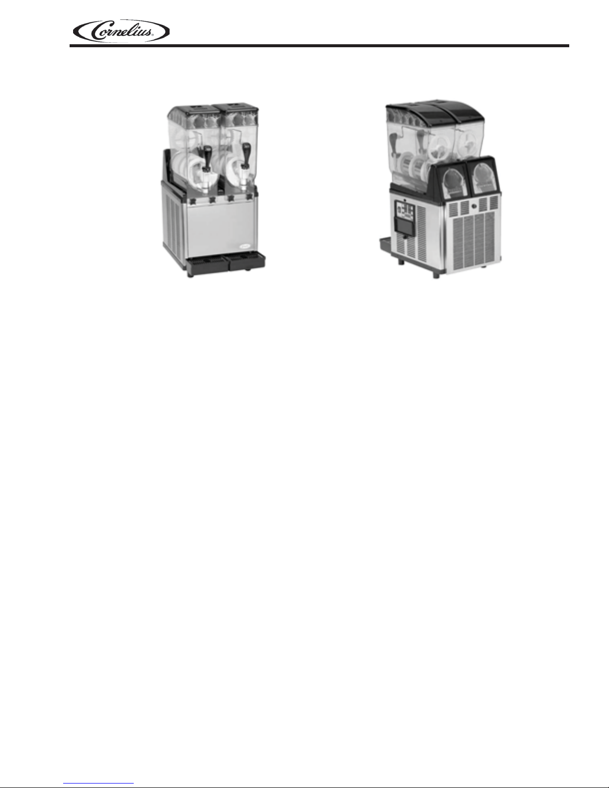
Ice Peak Training Manual
FIGURE 1
PRODUCT DESCRIPTION
Attractive Appearance
The dispensers project a stylish appearance with a brushed stainless steel body and clear plastic bowls.
The black lids accent the black drip trays and trim.
Merchandising
Illuminated merchandisers on bowl lids and at the rear attract attention and promote impulse sales. All
illuminated displays are equipped with long-life incandescent bulbs.
The large capacity 3.17 gal (12 ltr) bowls merchandise popular beverages such as frozen cappuccino,
frozen fruit drinks, frozen cocktails and much more.
Multi-Cooling System
Each bowl is equipped with its own 3/8 hp compressor and condenser that ensure fast cool down and
quick operation, by cooling the freeze cylinder. Note: the triple bowl 115v/60 Hz model is equipped with a
single 5/8 hp compressor. Product freezes on the cylinder and is shaved off by an auger that wraps
around the cylinder.
The multi-cooling system is especially beneficial in particularly warm applications, such as outdoor locations or in close proximity to hot kitchen environments. Environmentally friendly R-404a refrigerant is
used.
Certain models are equipped with an air filter that is built into the rear panel, ensuring an extended life for
cooling components.
FIGURE 2
Mixing System
The patented dual-mixing system provides optimal agitation of the product inside each bowl, ensuring
that a cold, consistent-tasting product is delivered in every cup. Mixing occurs with the bottom-mounted
auger and the top-mounted mixing rod. The system provides a rich, creamy-smooth and consistently icy
texture.
Controls
Electronic touch pad or traditional rocker switch controlled models are available. Electronic touch pad
controls provide advanced functionality and diagnostic capability. Advanced functionality includes daily
defrost times, bowl temp display, time display, and condenser filter alarm. In addition, the dispensers can
be set to the refrigeration mode, allowing overnight storage.
© 2003, IMI Cornelius Inc. - 3 - Publication Number: TP01057
Ice Peak Training Manual
OPTION SECTION
Electronic Control Board
Available on the Premium Line.
Electronic touch pad controls provide advanced functionality and diagnostic capability. Advanced functionality includes daily defrost times, bowl temp
display, time display, and condenser filter alarm. In
addition, the dispenser can be set to the refrigeration
mode, allowing overnight storage.
Advanced Features
• Programmable defrost time
• Time and bowl temp display
• Blocked filter alarm
• Over temp protection
Freeze Mode
While in the Freeze Mode the viscosity switch controls the compressor cycles. The switch is turned ON or
OFF by the auger motor which pivots as the product freezes and thaws, see Figures 61-66.
Refrigeration Mode
While in the Refrigeration Mode the compressor is controlled by temperature sensors that are located in
the evaporator, see Figures 42 and 43.
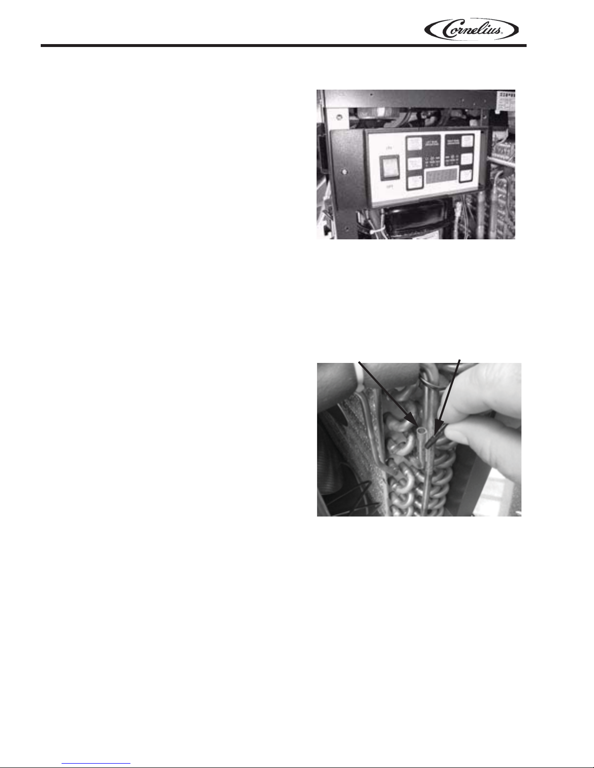
Over Temperature Sensor,
Electronic Controls
Over temperature sensor protects the compressor
from over heating.
FIGURE 3 Electronic Controls
Sensor Well
Sensor
Alarms
“Filter Cleaning” Alarm
A filter cleaning alarm will activate when the unit is
running hot due to insufficient internal air circulation.
When this occurs a “Filtr” message will appear on the
touch pad LED readout and an intermittent audible
tone will also sound to alert the operator of this condition.
The filter message will appear when the alarm activates (a beeping sound every 4-5 seconds). To determine the condition that caused the alarm and correct the problem, see the list of conditions below.
• Condition: The filter is dirty and needs to be cleaned.
Corrective Action: Clean/replace the filter.
• Condition: The unit is positioned too close to a wall or another object restricting air flow and causing the
machine to run at a higher temperature.
Corrective Action: Reposition the unit to maximize ventilation space.
• Condition: The filter in not properly installed.
Corrective Action: Properly install the filter.
• Condition: The unit has been installed near a heat source.
Corrective Action: Reposition the unit to maximize ventilation space.
Publication Number: TP01057 - 4 - © 2003, IMI Cornelius Inc.

“System Over Temperature” Alarm
A system over temperature alarm will activate as a safety when the unit have overheated to protect the
compressor.
The system automatically turns to OFF status and the compressor’s operation is stopped, while the augers
will keep working to avoid formation of ice blocks.
An “Err” message will appear on the touch pad LED readout accompanied by a continuous buzzer sound
to alert the operator of this condition.
Turn OFF all switches when the alarm activates. Then determine the condition.
Programming Electronic Touch Pad Models
Main Power Switch
• Turns unit ON.
• Selects 12/24 time or F/C temperature display when turned ON while simultaneously depressing the
auger button.
• Sets current time when turned ON while simultaneously depressing the “Mode/Press To Select Function” button.
Auger ON/OFF Button
• Turns auger ON and OFF when main power switch is ON.
• Must be ON to permit defrost time to be reset.
• Must be ON to activate the “Mode/Press To Select Function” button to select manual “OFF”, “FREEZE”
or “COOLING” functions.
Mode/Press To Select Function Button
• Used to manually select “OFF”, “FREEZE”, or “COOLING” functions when auger is turned ON.
• Accesses defrost time reset mode when depressed for an extended period when auger is turned ON.
• Locks in hours, minutes, and final time settings after they are reset using the “Auto Timer” button.
• Does not function when light on “Auto Timer” button is illuminated.
Ice Peak Training Manual
“Auto Timer” Button
• Turns auto defrost mode ON or OFF (light on switch indicates when auto defrost mode is activated).
• Used to adjust the hours and minutes settings when readjusting current time or auto defrost timer.
Enter Time Programming on Initial Installation or in the Event of a Time Change
1. Turn OFF power switch.
2. While pressing left “Press To Select Function” button, turn ON power switch while continuing to hold
the “PRess To Select Function” button until the display illuminates (hour digits will start to blink).
3. First set hour by pressing the “Auto Timer” clock button until the appropriate hour is shown (note:
when using a 12 hour clock the time is P.M. when the dot at the bottom right corner of the LED is lit;
when dot is not lit it is A.M.).
4. Press the left “Press To Select Function” button, to set the minutes, then press the “Auto Timer” clock
button until the appropriate minutes are set.
5. Press the “Press To Select Function” button one more time to save your settings.
Setting Defrost Timer (Night Setting)
1. Turn power switch ON.
2. Press “Auger ON/OFF” button ON for the side you are setting.
3. Press and hold the “Press To Select Function” button until you hear a long beep and the LED, “cold”
and the “Auto Timer” clock light begin to blink.
4. Press the “Auto Timer” clock button to set the hour you want it to turn to refrigeration mode and then
press the “Press To Select Function” button to save the setting.
5. Press the “Auto Timer” clock button to set the minutes to complete time setting that you want it to turn
to refrigeration mode, (defrost mode). Then press the “Press To Select Function” button to save the
setting.
© 2003, IMI Cornelius Inc. - 5 - Publication Number: TP01057

Ice Peak Training Manual
6. Press the “Auto Timer” clock button to set the minutes to complete time setting that you want it to turn
to refrigeration mode, (defrost mode). Then press the “Press To Select Function” button to save the
setting.
7. Proceed to setting the time you want the machine to turn to freezing mode by following steps 4 above.
Then press the “Press To Select Function” button to save the time settings for freeze mode. Freeze
light should be blinking.
NOTE: Once the settings have been saved, the unit will save the settings, even when the power
switch is turned OFF.
When the light on the “Auto Timer” clock button is ON the defrost timer is activated. To turn OFF the defrost
timer, press the “Auto Timer” clock button(s) until the light(s) on the clock button(s) turns off.
Operate in Automatic Mode (with Defrost Timer Activated)
1. Turn power switch ON and wait for LED to light up.
2. Press auger button ON for the side you are setting.
3. Press the “Auto Timer” button until it is illuminated, to operate in defrost mode.
4. When setting automatic times, please keep in mind it will take time for the frozen product to become
liquid or vice versa.
“Filter Cleaning” Alarm
A filter cleaning alarm will activate when the unit is running hot due to insufficient internal air circulation.
When this occurs a “Filter” message will appear on the touch pad LED display and an intermittent audible
tone will also sound to alert the operator of this condition.
The “Filter” message will appear when the alarm activates (a beeping sound every 4-5 seconds). To determine the condition that caused the alarm and correct the problem, see the list of conditions below:
• Condition: The filter is dirty and needs to be cleaned.
Corrective Action: Clean or replace filter following instructions (see “removing and cleaning filter”).
• Condition: The unit is positioned too close to a wall or other object restricting air flow and causing the
machine to run at a high temperature.
Corrective Action: Reposition until to maximize ventilation space (minimum 8” at rear and sides).
• Condition: The filter is not properly installed.
Corrective Action: Properly install filter (see “removing and cleaning filter”).
• Condition: The unit has been i8nstalled near a heat source, such as a coffee machine, ice maker, or
cold beverage machine which expels hot air from its vents, causing the machine to run at a high temperature. (Installation near a heat source should be avoided).
Corrective Action: Reposition unit to maximize ventilation space.
“System Over Temperature” Alarm
• A system over temperature alarm will activate as a safety when the unit has overheated to protect the
compressor.
• The system automatically goes to OFF status where the compressor’s operations is stopped, while
augers will keep working to avoid forming ice blocks.
• When this occurs an “Err” message will appear on the touch pad LED readout accompanied by a con-
tinuos buzzer sound to alert the operator of this condition.
• When this alarm activates, turn off all switches. Then determine the condition (see “Filter Cleaning”
Alarm section for conditions and corrective actions.
Publication Number: TP01057 - 6 - © 2003, IMI Cornelius Inc.
Ice Peak Training Manual
Operate in Manual Mode (without Defrost Timer Activated)
1. Turn power switch ON and wait for LED to light up.
2. Make sure clock button is OFF (LED light on clock button should not be lit up).
3. First turn auger ON by pressing “Auger ON/OFF” button until it beeps. (Note: The auger must be ON
before unit will allow the cooling or freezing mode to activate).
4. Select refrigeration or freezing mode by pressing the “Press To Select Function” button until the light
under the selection you desire is lit up.
NOTE: In the cooling mode, the LED will read the actual temperature of the product. (The temperature setting is preset to NSF standards and is not adjustable.) In the freezing mode the LED will
read the current time.
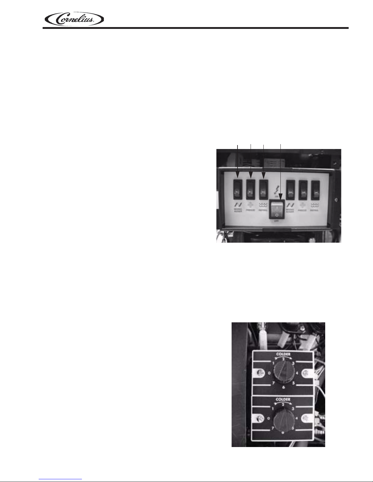
Rocker Switch Control Board
Available on Premium Models, Standard on Economy Model.
• Turn ON the main power switch (D).
Each bowl is controlled by 3 switches which have
the following functions:
• MIXING AUGER(A) - activates the mixing
parts/spiral auger
• FREEZE (B) - activates the freezing of the
product
• REFRIG (C) - activates the refrigeration of
the product (night/defrost setting).
• To obtain a slush
Select the MIXING (A) switch to activate the mixing parts/spiral auger and select the FREEZE (B)
switch to activate the freeze mode.
NOTE:There is a 4 minute delay before the compressor will start.
• To obtain cold (night/defrost) drinks
Select the MIXING (A) switch to activate the mixing parts/spiral auger and select the REFRIG (C) switch
to activate the refrigeration mode.
• Stand-by mode setting
Select the MIXING (A) switch to activate the mixing parts/spiral auger and select the REFRIG (C) switch
to activate the refrigeration mode to keep the product in the bowl cold overnight.
Bowl Temperature, Rocker Switch Models
Bowl Thermostats, Rocker Switch Models only.
ABC D
FIGURE 4 Rocker Switch Control
Used to maintain bowl temperature while in the
refrigeration mode.
Distributed By:
Commercial Refrigeration Service, Inc.
http://WWW.IceCubes.NET
http://WWW.JetsprayParts.COM
(623) 869-8881
(866) 423-6253
© 2003, IMI Cornelius Inc. - 7 - Publication Number: TP01057
FIGURE 5 Bowl Thermostat Controls

Ice Peak Training Manual
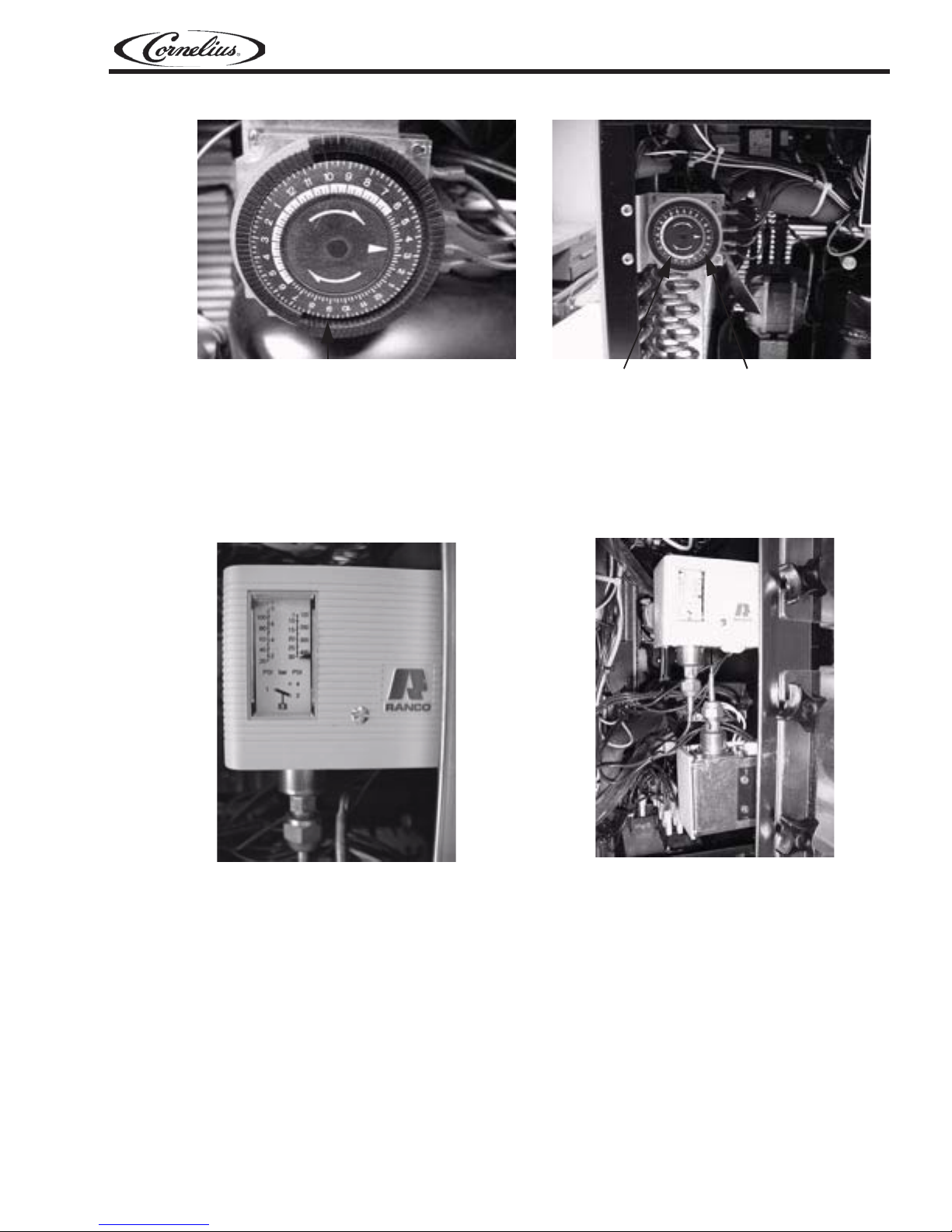
Setting Defrost, Rocker Switch Models
Setting current time
Rotate the program disc, in the direction of the arrows, to align the correct time of day with the time of day
mark.
Setting defrost mode
Set the defrost period by pushing the switch actuator toward the outer edge of the program disc. Freeze
time is set by pushing the switch actuators toward the center of the time switch. The light and dark shaded
areas of the program disc indicate day and night respectively. Each actuator is equivalent to 15 minutes.
All switches (power, auger, refrigeration, and freeze) must be ON for defrost timer to properly function.
NOTE: The timer is battery backed. Do not remove power from the unit for greater than 2 weeks as
doing so will result in failure of the battery back-up feature. The battery is nickel cadmium and will
last from 6 to 8 years if properly charged. The battery is not replaceable upon failure.
Setting Defrost Timer (Night Setting)
1. Turn the power switch ON. Make sure the “Auto Time” is OFF (light on button is not lit).
2. Press the “Auger ON/OFF” button ON for the side you are setting.
3. Press and hold the “Press To Select Function” button until you hear a long beep and the LED, “Cold”
and the “Auto Timer” clock light begins to blink.
4. Press the “Auto Timer” clock button to set the hour you want it to turn to refrigeration mode, (defrost
mode) and then press the
5. Press the “Auto Timer” clock button to set the minutes to complete time setting that you want it to turn
to refrigeration mode (defrost mode). Then press the “Press To Select Function” button to save the
minute setting. The “Cold” light will turn off and the “Freeze” light and “Auto Time” light will begin blinking.
6. Set the time you want the machine to turn to freezing mode by following steps 1 - 5 above. Then
press the “Press To Select Function” button to save the time settings for freeze mode. The freeze light
should be blinking.
NOTE: Once the settings have been saved, the unit will keep the settings, even when the power
switch is turned OFF.
When the light on the “Auto Timer” clock button is “ON”, the defrost timer is activated. To turn OFF
the defrost timer, press the “Auto Timer” clock button(s) until the light(s) on the clock button(s)
turns off.
“Press To Select Function” button to save the hour setting.
Operate in Automatic Mode (with Defrost Timer Activated)
1. Turn power switch ON and wait for LED display to light up.
2. Press auger button ON for the side you are setting.
3. To operate in defrost mode press the “Auto Timer” button until it is illuminated.
4. When setting automatic times, please keep in mind it will take time for the frozen product to become
liquid or vice versa.
Operate in Manual Mode (without Defrost Timer Activated)
1. Turn the power switch ON and wait for LED display to light up.
2. Make sure the clock button is OFF (LED light on clock button should not be lit up).
3. First turn auger on by pressing the “Auger ON/OFF” button until it beeps.
NOTE: The auger must be on before the unit will allow the cooling or freezing mode to be activated).
4. Then select refrigeration or freezing mode by pressing the “Press To Select Function” button until the
light under the selection you desire is lit up.
NOTE: In the cooling mode, the LED will read the actual temperature of the product (the temperature setting is preset to NSF standards and is not adjustable.) In the “Freeze” or “Off” mode the
LED will read the current time.
Publication Number: TP01057 - 8 - © 2003, IMI Cornelius Inc.
Ice Peak Training Manual
Slide the cogs back and forth to set times in 15
minute increments.
FIGURE 6
White is Day Time
High Pressure Cut Out Switch, Rocker Switch Models
The Rocker Switch Models have high pressure cut out switches that protect the compressor.
They are factory set at: Cut Out 30 bar; Cut In 22 bar
NOTE: It is a good idea to confirm the settings at the time of installation and when ever service
work is performed.
Black is Night Time
FIGURE 7
FIGURE 8
© 2003, IMI Cornelius Inc. - 9 - Publication Number: TP01057
FIGURE 9
Ice Peak Training Manual
OPTIONAL ACCESSORIES
Auto Fill
Installation and Operation
The Cornelius Auto Fill Kit is intended for use with
5:1 BIB (Bag-In-Box) syrup concentrates. Other
ratios are available by request. To install and
operate the Auto Fill Kit, follow the instructions
below.
1. Place the Auto Fill black box in close proximity to the Granita Auto Fill dispenser.
2. Attach a ½” I.D. (1.3cm) beverage grade
water supply line to the male water inlet fitting on the side of the Auto Fill box using the
supplied fitting and worm gear clamp.
3. Attach 3/8” I.D. (0.95cm) syrup supply lines
to the syrup inlet fittings on each Shurflo®
Brix Pump. Secure the syrup lines using the
supplied Oetiker clamps.
4. Insert 3/8” O.D. (0.95cm) beverage grade
tubing into the John Guest® fittings located
at the top of the Auto Fill box. There are individual outputs for syrup and water.
Publication Number: TP01057 - 10 - © 2003, IMI Cornelius Inc.
FIGURE 10

Security Kit Installation
Installing Locking Clip
1. Close the tap.
2. Attach a padlock in hole provided on the locking clip.
3. The lock is not provided.
NOTE: The 3/8” O.D. (0.95cm) tubing is not supplied with the Auto Fill Kit and is sold separately.
Cornelius part number is 620708970.
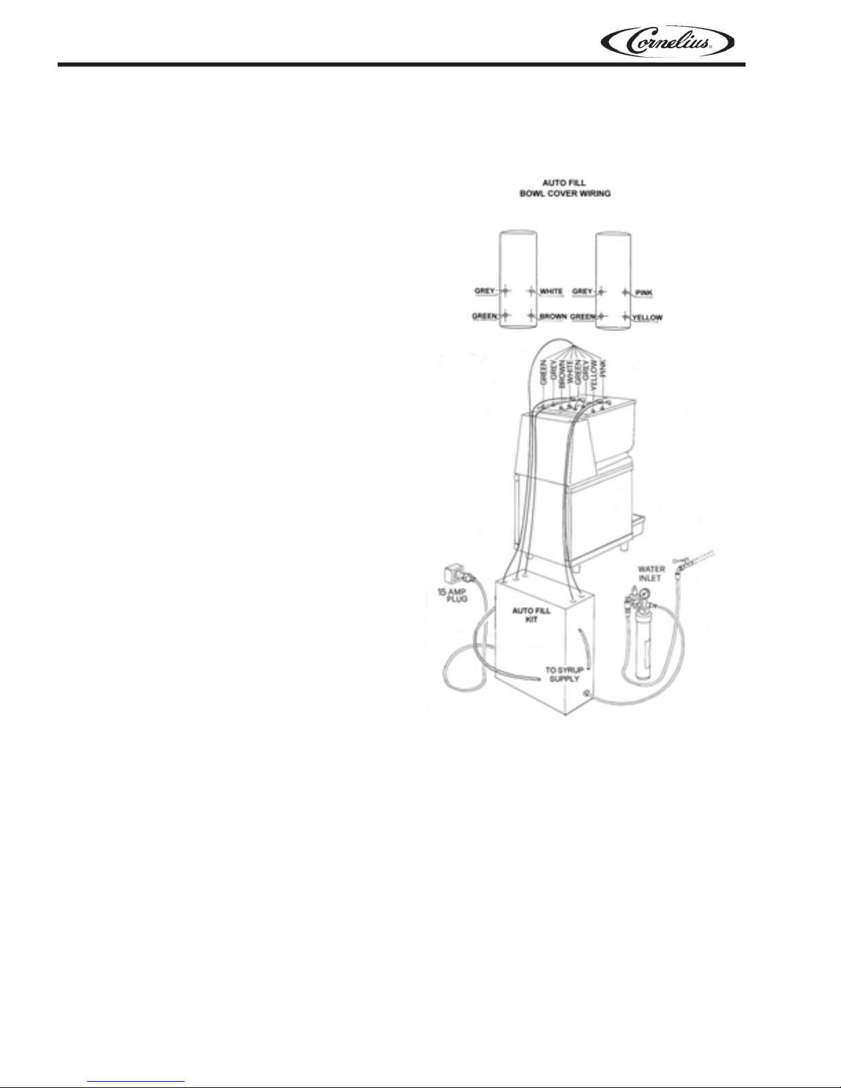
4. Remove the lower rear panel from the Granita Auto Fill dispenser. Route the 3/8” syrup and water
lines from the Auto Fill box up through the back of the Granita Auto Fill dispenser. Attach a syrup
and water line to each respective bowl as shown.
5. Attach the gray wire harness, coiled inside the Auto Fill box, to the
liquid level sensing probes on each product bowl lid. Route the
gray harness up through the backside of the dispenser and
attached the wires as shown.
6. Turn on the water supply and plug the Auto Fill box into the proper
power outlet.
7. The water regulator inside the Auto Fill box is factory preset
to approximately 43 PSIG (3 bar) which is the preferred setting
required to operate the ShurFlo® Brix Pumps.
If adjustment is necessary, loosen nut “B”. Turn Nut “A” clockwise to
increase the pressure and counter-clockwise to decrease the pressure.
Ice Peak Training Manual
FIGURE 11
IMPORTANT: DO NOT SET THE WATER PRESSURE HIGHER THAN
50 PSIG (3.4 BAR). REFER TO THE SHURFLO® INSRTRUCTIONS
PACKAGED WITH THE AUTO FILL BOX FOR INSTRUCTIONS ON
PERIODIC CLEANING AND MAINTENANCE OF THE BRIX PUMPS.
FIGURE 12
© 2003, IMI Cornelius Inc. - 11 - Publication Number: TP01057

Ice Peak Training Manual
Electrical Diagram Black Box Auto Fill
FIGURE 13
Brix Pumps
Water Inlet
FIGURE 14. Water Inlet Connection
Probe
Connections
Publication Number: TP01057 - 12 - © 2003, IMI Cornelius Inc.
 Loading...