

Cornelius Flavorfusion TP01070 Training Manual
®
FLAVORFUSION®/
FLAVOROVERLOAD
Training Manual
Publication Number: TP01070
Revision Date: November 16, 2007
Revision: F
Visit the IMI Cornelius web site at www.cornelius.com
for all your Literature needs.

FLAVORFUSION®/FLAVOROVERLOAD
TRAINING MANUAL
The products, technical information, and instructions contained in this manual are subject
to change without notice. These instructions are not intended to cover all details or variations of the equipment, nor to provide for every possible contingency in the installation,
operation or maintenance of this equipment. This manual assumes that the person(s)
working on the equipment have been trained and are skilled in working with electrical,
plumbing, pneumatic, and mechanical equipment. It is assumed that appropriate safety
precautions are taken and that all local safety and construction requirements are being
met, in addition to the information contained in this manual.
To inquire about current revisions of this and other documentation or for assistance with
any Cornelius product contact:
www.cornelius.com
800-238-3600
Trademarks and Copyrights:
Aurora, Cornelius, FlavorFusion, Focus, Leopard ERV, Nordic, Optifill, Pinnacle, SFV1,
Smart-Pour, Totalflex II, and Vanguard are registered trademarks of IMI Cornelius Inc.
This document contains proprietary information and it may not be
reproduced in any way without permission from Cornelius.
Printed in U.S.A.
Copyright © 2004-2007, All Rights Reserved, IMI Cornelius Inc.

FlavorFusion®/FlavorOverload Training Manual
TABLE OF CONTENTS
Product Overview . . . . . . . . . . . . . . . . . . . . . . . . . . . . . . . . . . . . . . . . . . . . . . . . . . . . 1
Theory of Operation . . . . . . . . . . . . . . . . . . . . . . . . . . . . . . . . . . . . . . . . . . . . . . . . . . . 1
System Requirements . . . . . . . . . . . . . . . . . . . . . . . . . . . . . . . . . . . . . . . . . . . . . . . . . 2
Programming . . . . . . . . . . . . . . . . . . . . . . . . . . . . . . . . . . . . . . . . . . . . . . . . . . . . . . . . . 3
Programming Mode Flashing Sequences . . . . . . . . . . . . . . . . . . . . . . . . . . . . . . 3
Setting Water Flow Rate . . . . . . . . . . . . . . . . . . . . . . . . . . . . . . . . . . . . . . . . . . . 4
Adjusting Syrup/Water Ratio (Brix) . . . . . . . . . . . . . . . . . . . . . . . . . . . . . . . . . . . 5
Setting a Button to Dispense Non-carbonated Water Only . . . . . . . . . . . . . . . . . 5
Setting a Button to Dispense Carbonated Water Only . . . . . . . . . . . . . . . . . . . . 5
Mechanical . . . . . . . . . . . . . . . . . . . . . . . . . . . . . . . . . . . . . . . . . . . . . . . . . . . . . . . . . . . 6
Disassembly . . . . . . . . . . . . . . . . . . . . . . . . . . . . . . . . . . . . . . . . . . . . . . . . . . . . . . . 6
Control Box Components . . . . . . . . . . . . . . . . . . . . . . . . . . . . . . . . . . . . . . . . . . 6
Valve Removal . . . . . . . . . . . . . . . . . . . . . . . . . . . . . . . . . . . . . . . . . . . . . . . . . . . . . 7
Valve Service . . . . . . . . . . . . . . . . . . . . . . . . . . . . . . . . . . . . . . . . . . . . . . . . . . . . . . 9
Carbonator Tank . . . . . . . . . . . . . . . . . . . . . . . . . . . . . . . . . . . . . . . . . . . . . . . . . . . . 9
Motor Removal . . . . . . . . . . . . . . . . . . . . . . . . . . . . . . . . . . . . . . . . . . . . . . . . . . . . . 9
System Plumbing Diagram . . . . . . . . . . . . . . . . . . . . . . . . . . . . . . . . . . . . . . . . . . . 10
Plumbing Diagram . . . . . . . . . . . . . . . . . . . . . . . . . . . . . . . . . . . . . . . . . . . . . . . . . . 11
Interface Board and Harness Pin-out Detail . . . . . . . . . . . . . . . . . . . . . . . . . . . . . . 12
Point-Point Wiring Diagram . . . . . . . . . . . . . . . . . . . . . . . . . . . . . . . . . . . . . . . . . . . 13
Ladder Type Wiring Diagram . . . . . . . . . . . . . . . . . . . . . . . . . . . . . . . . . . . . . . . . . 14
Troubleshooting . . . . . . . . . . . . . . . . . . . . . . . . . . . . . . . . . . . . . . . . . . . . . . . . . . . 15
Diagnostics Guide for the Main Control Board (see FIGURE 22) . . . . . . . . . . . . . . 19
© 2004-2007, IMI Cornelius Inc. - i - Publication Number: TP01070

FlavorFusion®/FlavorOverload Training Manual
Publication Number: TP01070 - ii - © 2004-2007, IMI Cornelius Inc.

FlavorFusion®/FlavorOverload Training Manual
PRODUCT OVERVIEW
• Brand density - 16 brands (14 chilled, 2 ambient) plus up to 8 bonus flavors in 30” wide;
• 255 lbs capacity cube ice only hopper;
• Internal cold carbonation with remote pump;
• Total carb/non-carb flexibility on each brand;
• Eye catching merchandising;
• Improved serviceability of agitator motor;
• Bonus flavors programmable for 1-4 second dispense;
• Valve positions programmable without special tools or PDA;
• Front inlet fittings;
• Key lock switch;
• 10” cup clearance;
• 30% more drip tray capacity;
THEORY OF OPERATION
• The FlavorFusion®/FlavorOverload machine is an above counter ice/beverage unit with multi flavor
nozzles and the capability to inject bonus flavors into the finished drink.
• The beverage is cooled via ice melting on an aluminum cold plate. Ice is kept on the cold plate by
means of an opening in the hopper that drops ice onto the surface during agitation of the ice in the
hopper.
• The unit contains a mechanical ice chute and gate mechanism.
• The ice agitation gear motor is removable from the gear box to ease removal of the motor during ser-
vice and lower repair cost.
• The unit has six nozzles for dispensing brand and bonus flavors.
• Each brand nozzle serves four discreet flavors fed by four syrup valves, one plain water, and one carb
water valve. Every position is flexible for use with either carb or non-carb water.
• Each bonus nozzle serves four individual flavors intended for injection into the finished drink. Bonus
nozzles are fed by four syrup valves only. There is no option to dispense water out of the bonus nozzle
without significant plumbing changes.
• Bonus flavors require a separate regulator setting on their BIB pumps (20 psi maximum).
• Brand and bonus flavors are controlled by means of six interface boards (one interface board per noz-
zle). The interface boards are common for each nozzle. Valve positions are configured on the membrane switch. No special tool or PDA is required.
• Valve flow rates are adjustable for 3.0-3.75 oz/sec finished drink dispense rate.
• Unplug the unit or turn off the key switch before attempting any electrical service on the unit, failure to
do this can cause damage to the electrical components!
© 2004-2007, IMI Cornelius Inc. - 1 - Publication Number: TP01070
FlavorFusion® Training Manual
SYSTEM REQUIREMENTS
Dimensions (in): . . . . . . . . 29 x 30 x 39 (l x w x h). Height is measured to top of bin. Lid adds 3 in to
height.
Counter Weight (lb): . . . . . 320 (plus ice weight)
Shipping Weight (lb): . . . . 330
Capacity: . . . . . . . . . . . . . 250 lb ice bin capacity (cube ice only)
Indoor installation only
o
40 to 90
Electrical Rating: . . . . . . . . 103-132 Volts
Water supply pressure: . . 50-60 psi at pump
Water volume: . . . . . . . . . 125 gph
CO2: . . . . . . . . . . . . . . . . . 75 psi at carbonator tank
Syrup (brands): . . . . . . . . 60 psi min
Syrup (bonus): . . . . . . . . 20 psi max
F ambient temperature
11 Amps
Syrup supply lines: . . . . . . .375” ID tubing min
NOTE: If water pressure is below 50 psi a water pressure booster is required for still water drinks.
Publication Number: TP01070 - 2 - © 2004-2007, IMI Cornelius Inc.
PROGRAMMING
NOTE: The programming mode is exactly the same for both brand and bonus keypads.
To enter the programming mode, press and hold the two program buttons (see FIGURE 3) at the top of
the keypad for approximately 4 seconds. All keypad LEDs will flash off for approximately 1 second to
indicate the start of the programming mode.
To exit programming mode, press and hold the two program buttons for approximately 4 seconds. All
keypad LEDs will flash off for approximately 1 second, resuming normal operation mode.
Programming Mode Flashing Sequences
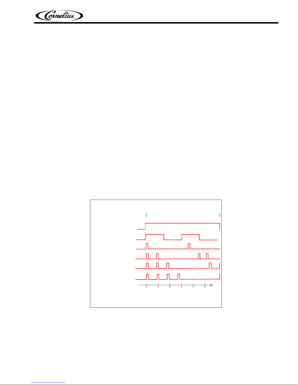
Once in programming mode, each dispense button LED flashes in a sequence cycle according to one (1)
of six (6) dispense types. For Brand Keypads, only dispense types 1 and 2 should be used. For Bonus
Flavor Keypads, dispense types 3 through 6 are used. The six (6) dispense types are described below,
and shown in a timing diagram in FIGURE 1:
• Dispense Type 1, Carbonated water dispense: Solid LED
• Dispense Type 2, Non-carbonated dispense: Flashing LED 1.5 seconds ON, 1.5 seconds OFF
• Dispense Type 3, 1-second flavor shot: LED flashes once for ¼ second, followed by 3 seconds
OFF
• Dispense Type 4, 2-second flavor shot: LED flashes twice for ¼ second ON, ½ second OFF,
followed by 3 seconds OFF
• Dispense Type 5, 3-second flavor shot: LED flashes three (3) times for ¼ second ON, ½ second
OFF, followed by 3 seconds OFF
• Dispense Type 6, 4-second flavor shot: LED flashes four (4) times for ¼ second ON, ½ second
OFF, followed by 3 seconds OFF
Start
proramming
mode
FlavorFusion®/FlavorOverload Training Manual
Exit
programming
mode
1. Carbonated water dispense
2. Non-carbonated dispense
3. 1-second flavor shot
4. 2-second flavor shot
5. 3-second flavor shot
6. 4-second flavor shot
012345
Time
(seconds)
FIGURE 1
NOTE: It is possible to program a flavor shot into a keypad. It is also possible to program a cove
dispense (type 1 or 2) into a flavor shot keypad. Both instances result in an incorrect operation
and should be corrected.
© 2004-2007, IMI Cornelius Inc. - 3 - Publication Number: TP01070
FlavorFusion® Training Manual
Setting Water Flow Rate
Setting the water flow rate will require a timed dispense. To accomplish this, the following procedure
should be followed:
1. Enter programming mode for the valve
block by simultaneously pressing and
holding both programming buttons for 4
seconds (see FIGURE 3). The LED’s for
flavors 1-4 should flash off and then back
on. The drink icon should turn off.
2. Set the valve block to a 4 second pour
mode by simultaneously pressing and
holding Flavor 1 and Flavor 4 buttons until
the flash pattern for all four buttons
changes.
3. Place an empty ratio cup under the
appropriate nozzle and press the left
program button for a 4 second dispense of
carbonated water. There should be
approximately 10 oz. dispensed.
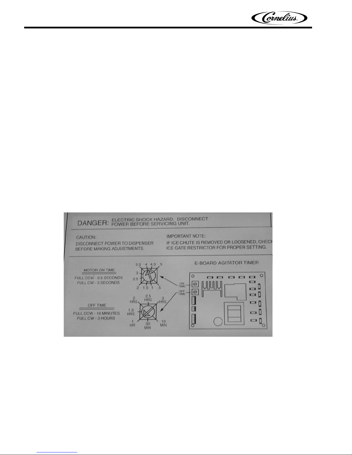
4. If necessary, adjust the water flow control
(see FIGURE 2), empty ratio cup, and
repeat step 3. Otherwise empty ratio cup
and repeat step 3 using the right program
button for plain water.
5. Exit 4 second pour mode by simultaneously pressing and holding Flavor 1 and Flavor 4
buttons until the flash pattern for all for buttons changes.
6. Exit programming mode by simultaneously pressing and holding both programming buttons
for 4 seconds.
Flow Adjuster Detail
(Water)
FIGURE 2. Valve with Flow Adjusters
(see plumbing diagram for plumbing and valve
configuration)
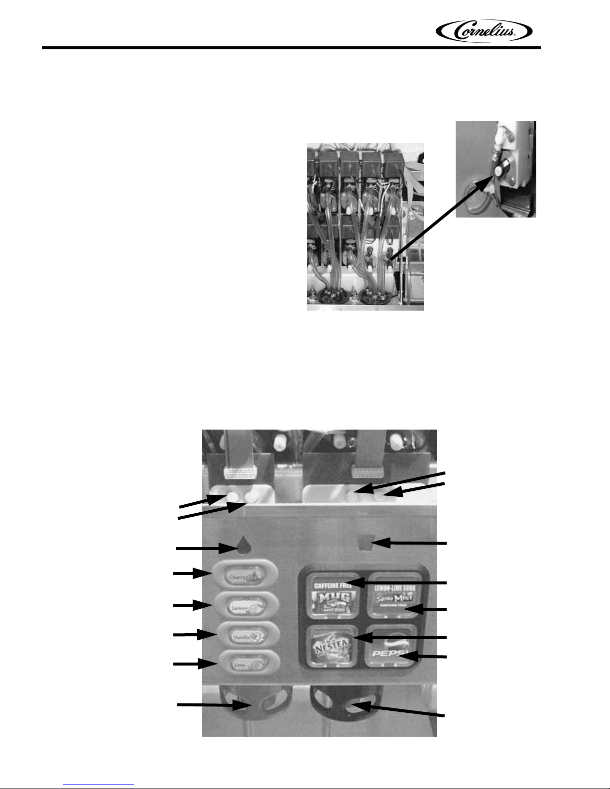
Bonus Flavor
Programming
Buttons
(Left
and Right)
Bonus Flavor Icon
Bonus Flavor Button 1
Bonus Flavor Button 2
Bonus Flavor Button 3
Bonus Flavor Button 4
Bonus Flavor Nozzle
Brand Flavor
Programming
Buttons
(Left and
Right)
Drink Icon
Brand Flavor Button 1
Brand Flavor Button 2
Brand Flavor Button 3
Brand Flavor Button 4
Brand Flavor Nozzle
Publication Number: TP01070 - 4 - © 2004-2007, IMI Cornelius Inc.
 Loading...