

Cornelius FCB POST-MIX DISPENSER Installation & Service Manual
IMI CORNELIUS INC g One Cornelius Place g Anoka, MN 55303-6234
Telephone (800) 238-3600 Facsimile (612) 422-3246
Installation/Service
Manual
FCB POST-MIX DISPENSER
TWO OR FOUR-FLAVOR
W/HOT-GAS DEFROST
AND V3+FEATURES
IMPORTANT:
TO THE INSTALLER
It is the responsibility of the Installer
to ensure that the water supply to
the dispensing equipment is
provided with protection against
backflow by an air gap as defined in
ANSI/ASME A112. 1.2-1979; or an
approved vacuum breaker or other
such method as proved effective by
test.
Water pipe connections and fixtures
directly connected to a potable
water supply shall be sized,
installed, and maintained according
to federal, state, and local laws.
Part No. 2813
October 13, 1993
Revised: March 28, 1995
THIS DOCUMENT CONTAINS IMPORTANT INFORMATION
This Manual must be read and understood before installing or operating this equipment
IMI CORNELIUS INC; 1993–95
PRINTED IN U.S.A

GENERAL INFORMATION 1. . . . . . . . . . . . . . . . . . . . . . . . . . . . . . . . . . . . . . . . . . . . . . . . . .
GENERAL DESCRIPTION 1. . . . . . . . . . . . . . . . . . . . . . . . . . . . . . . . . . . . . . . . . . . . . .
UNIT DESCRIPTION 1. . . . . . . . . . . . . . . . . . . . . . . . . . . . . . . . . . . . . . . . . . . . . . . . . . .
TWO-FLAVOR FCB DISPENSER 1. . . . . . . . . . . . . . . . . . . . . . . . . . . . . . . . . . . .
FOUR-FLAVOR FCB DISPENSER 1. . . . . . . . . . . . . . . . . . . . . . . . . . . . . . . . . . .
REFRIGERATION SYSTEMS 3. . . . . . . . . . . . . . . . . . . . . . . . . . . . . . . . . . . . . . .
THEORY OF OPERATION 3. . . . . . . . . . . . . . . . . . . . . . . . . . . . . . . . . . . . . . . . . . . . . .
DEFROST SYSTEMS 4. . . . . . . . . . . . . . . . . . . . . . . . . . . . . . . . . . . . . . . . . . . . . . . . . .
MANUAL DEFROST SYSTEM 4. . . . . . . . . . . . . . . . . . . . . . . . . . . . . . . . . . . . . .
AUTOMATIC DEFROST SYSTEM 4. . . . . . . . . . . . . . . . . . . . . . . . . . . . . . . . . . .
‘‘SLEEP’’ (SLEEP TIME) 5. . . . . . . . . . . . . . . . . . . . . . . . . . . . . . . . . . . . . . . . . . . . . . . .
‘‘WAKE UP’’ (WAKE UP TIME) 5. . . . . . . . . . . . . . . . . . . . . . . . . . . . . . . . . . . . . . . . . . .
INSTALLATION 9. . . . . . . . . . . . . . . . . . . . . . . . . . . . . . . . . . . . . . . . . . . . . . . . . . . . . . . . . . . .
UNPACKING AND INSPECTION 9. . . . . . . . . . . . . . . . . . . . . . . . . . . . . . . . . . . . . . . .
IDENTIFICATION OF LOOSE-SHIPPED PARTS 9. . . . . . . . . . . . . . . . . . . . . . . . . . .
ELECTRICAL POWER REQUIREMENTS 10. . . . . . . . . . . . . . . . . . . . . . . . . . . . . . . . .
TWO-FLAVOR FCB DISPENSER 10. . . . . . . . . . . . . . . . . . . . . . . . . . . . . . . . . . . .
FOUR-FLAVOR FCB DISPENSER 10. . . . . . . . . . . . . . . . . . . . . . . . . . . . . . . . . . .
SELECTING LOCATION 10. . . . . . . . . . . . . . . . . . . . . . . . . . . . . . . . . . . . . . . . . . . . . . . .
INSTALLING UNIT 11. . . . . . . . . . . . . . . . . . . . . . . . . . . . . . . . . . . . . . . . . . . . . . . . . . . . .
PLACING UNIT IN OPERATING LOCATION 11. . . . . . . . . . . . . . . . . . . . . . . . . .
INSTALLING DRIP TRAY SUPPORTS, DRIP TRAY, AND CUP REST 11. . . .
INSTALLING DRIP TRAY DRAIN HOSE KIT 11. . . . . . . . . . . . . . . . . . . . . . . . . .
INSTALLING PRIMARY CO2 REGULATOR ASSEMBLY ON CO2
CYLINDER 13. . . . . . . . . . . . . . . . . . . . . . . . . . . . . . . . . . . . . . . . . . . . . . . . . . . . . . .
CONNECTING SOFT DRINK TANKS CO2 LINES TO PRIMARY CO2
REGULATOR ASSEMBLY 14. . . . . . . . . . . . . . . . . . . . . . . . . . . . . . . . . . . . . . . . . .
PREPARING UNIT SYRUP INLET LINES FOR CONNECTION TO SOFT
DRINK TANKS 14. . . . . . . . . . . . . . . . . . . . . . . . . . . . . . . . . . . . . . . . . . . . . . . . . . . .
CONNECTING CITY PLAIN WATER SOURCE LINE (S) TO UNIT 14. . . . . .
CONNECTING ELECTRICAL POWER CIRCUIT TO UNIT 15. . . . . . . . . . . . .
PREPARATION FOR OPERATION 16. . . . . . . . . . . . . . . . . . . . . . . . . . . . . . . . . . . . . . .
TURNING ON ELECTRICAL POWER TO UNIT 16. . . . . . . . . . . . . . . . . . . . . . .
TURNING ON CO2 SUPPLY TO UNIT 16. . . . . . . . . . . . . . . . . . . . . . . . . . . . . . .
TURNING ON CITY PLAIN WATER SOURCE LINE TO UNIT 16. . . . . . . . . . .
CONNECTING SOFT DRINK TANKS TO UNIT SYRUP SYSTEMS 17. . . . . .
ADJUSTING BRIX (WATER-TO-SYRUP) ‘‘RATIO’’ OF DISPENSED
PRODUCT 17. . . . . . . . . . . . . . . . . . . . . . . . . . . . . . . . . . . . . . . . . . . . . . . . . . . . . . . .
FILLING FREEZE CYLINDERS WITH PRODUCT 18. . . . . . . . . . . . . . . . . . . . .
ADJUSTING “WATER-COOLED” UNITS REFRIGERATION SYSTEM(S)
VARIABLE WATER REGULATOR(S) 18. . . . . . . . . . . . . . . . . . . . . . . . . . . . . . . . .
ADJUSTING BEATER MOTOR CURRENT (EITHER SIDE) 18. . . . . . . . . . . .
PROGRAMMING MAIN MENU SELECTIONS ONTO THE MESSAGE
DISPLAY 18. . . . . . . . . . . . . . . . . . . . . . . . . . . . . . . . . . . . . . . . . . . . . . . . . . . . . . . . .
SETTING ‘‘CLOCK’’ (TIME OF DAY) 18. . . . . . . . . . . . . . . . . . . . . . . . . . . . . . . .
PROGRAMMING ‘‘DEFROST’’ (AUTOMATIC) SETTINGS INTO THE UNIT 19
PROGRAMMING ‘‘SLEEP’’ (SLEEP TIME) INTO THE UNIT 19. . . . . . . . . . . .
PROGRAMMING ‘‘WAKE UP’’ (WAKE UP) TIME INTO THE UNIT 19. . . . . . .
i
2813

TABLE OF CONTENTS
PROGRAMMING POINT OF SALE MESSAGE DISPLAY 19. . . . . . . . . . . . . . .
ADJUSTING ‘‘VIS SET’’ (PRODUCT VISCOSITY) OF DISPENSED
PRODUCT 19. . . . . . . . . . . . . . . . . . . . . . . . . . . . . . . . . . . . . . . . . . . . . . . . . . . . . . . .
“VIS READ” (ACTUAL VISCOSITY READOUT) OF PRODUCT IN
FREEZE CYLINDERS 19. . . . . . . . . . . . . . . . . . . . . . . . . . . . . . . . . . . . . . . . . . . . . .
DISPLAYED EVAPORATOR REFRIGERATION COILS INLETS AND
COMMON OUTLET SENSORS TEMPERATURES 19. . . . . . . . . . . . . . . . . . . .
‘‘VOLTAGE’’ (DISPLAYED VOLTAGE READOUT) 19. . . . . . . . . . . . . . . . . . . . . .
PROGRAMMING COMPONENTS ‘‘DIAGNOSE’’ (DIAGNOSTIC MODE)
INTO THE UNIT 20. . . . . . . . . . . . . . . . . . . . . . . . . . . . . . . . . . . . . . . . . . . . . . . . . . .
DISPLAYING ‘‘TOTALS’’ (DISPLAYED CYCLES AND HOURS TOTALS) ON
TO THE MESSAGE DISPLAY 20. . . . . . . . . . . . . . . . . . . . . . . . . . . . . . . . . . . . . . .
PROGRAMMING FREEZE CYLINDERS BEATER “MOTORS” INTO UNIT
ELECTRONICS 20. . . . . . . . . . . . . . . . . . . . . . . . . . . . . . . . . . . . . . . . . . . . . . . . . . .
PROGRAMMING PROPER REFRIGERANT TYPE INTO UNIT
ELECTRONICS 20. . . . . . . . . . . . . . . . . . . . . . . . . . . . . . . . . . . . . . . . . . . . . . . . . . .
DISPLAYED ERROR CONDITIONS 20. . . . . . . . . . . . . . . . . . . . . . . . . . . . . . . . . . . . . .
INSTALLING CONTROL BOX COVER AND BACK, SIDES LOWER ACCESS,
AND TOP PANELS ON UNIT 20. . . . . . . . . . . . . . . . . . . . . . . . . . . . . . . . . . . . . . . . . . . .
OPERATORS INSTRUCTIONS 21. . . . . . . . . . . . . . . . . . . . . . . . . . . . . . . . . . . . . . . . . . . . . .
Page
CONTROL PANEL SWITCHES AND DISPLAYED MESSAGES 21. . . . . . . . . . . . . .
CONTROL PANEL SWITCHES 21. . . . . . . . . . . . . . . . . . . . . . . . . . . . . . . . . . . . . .
CONTROL PANEL DISPLAY MESSAGES 22. . . . . . . . . . . . . . . . . . . . . . . . . . . .
FREEZE CYLINDERS MANUAL OR AUTOMATIC DEFROST SYSTEMS 23.
MANUAL DEFROST SYSTEM 23. . . . . . . . . . . . . . . . . . . . . . . . . . . . . . . . . . . . . .
AUTOMATIC DEFROST SYSTEM 23. . . . . . . . . . . . . . . . . . . . . . . . . . . . . . . . . . .
‘‘SLEEP’’ (SLEEP TIME) 24. . . . . . . . . . . . . . . . . . . . . . . . . . . . . . . . . . . . . . . . . . . . . . . .
‘‘WAKE UP’’ (WAKE UP TIME) 24. . . . . . . . . . . . . . . . . . . . . . . . . . . . . . . . . . . . . . . . . . .
FACEPLATE RELIEF VALVES 24. . . . . . . . . . . . . . . . . . . . . . . . . . . . . . . . . . . . . . . . . . .
PRODUCT SAMPLE VALVES 24. . . . . . . . . . . . . . . . . . . . . . . . . . . . . . . . . . . . . . . . . . .
PRODUCT SHUTOFF VALVES 24. . . . . . . . . . . . . . . . . . . . . . . . . . . . . . . . . . . . . . . . . .
PRIMARY CO2 REGULATOR 24. . . . . . . . . . . . . . . . . . . . . . . . . . . . . . . . . . . . . . . . . . .
SECONDARY CO2 REGULATORS 24. . . . . . . . . . . . . . . . . . . . . . . . . . . . . . . . . . . . . .
CARBONATED WATER FLOW REGULATORS 24. . . . . . . . . . . . . . . . . . . . . . . . . . . .
SYRUP FLOW REGULATORS 25. . . . . . . . . . . . . . . . . . . . . . . . . . . . . . . . . . . . . . . . . .
DISPENSING VALVES 25. . . . . . . . . . . . . . . . . . . . . . . . . . . . . . . . . . . . . . . . . . . . . . . . .
DISPENSED PRODUCT CONDITIONS 25. . . . . . . . . . . . . . . . . . . . . . . . . . . . . . . . . . .
‘‘OVERRUN’’, AS APPLIED TO FROZEN CARBONATED BEVERAGES 25. .
OPERATING CHARACTERISTICS 26. . . . . . . . . . . . . . . . . . . . . . . . . . . . . . . . . . . . . . .
OPERATING UNIT 26. . . . . . . . . . . . . . . . . . . . . . . . . . . . . . . . . . . . . . . . . . . . . . . . . . . . .
REPLENISHING SYRUP SUPPLY 26. . . . . . . . . . . . . . . . . . . . . . . . . . . . . . . . . . . . . . .
PRODUCT FLAVOR CHANGE 27. . . . . . . . . . . . . . . . . . . . . . . . . . . . . . . . . . . . . . . . . .
CHECKING CO2 SUPPLY 27. . . . . . . . . . . . . . . . . . . . . . . . . . . . . . . . . . . . . . . . . . . . . .
CLEANING AND SANITIZING 27. . . . . . . . . . . . . . . . . . . . . . . . . . . . . . . . . . . . . . . . . . .
DAILY CLEANING 27. . . . . . . . . . . . . . . . . . . . . . . . . . . . . . . . . . . . . . . . . . . . . . . . .
SANITIZING 27. . . . . . . . . . . . . . . . . . . . . . . . . . . . . . . . . . . . . . . . . . . . . . . . . . . . . .
2813
ii

TABLE OF CONTENTS
CLEANING CONDENSER COIL 27. . . . . . . . . . . . . . . . . . . . . . . . . . . . . . . . . . . . . . . . .
UNIT WITH AIR-COOLED REFRIGERATION SYSTEM 27. . . . . . . . . . . . . . . .
UNIT WITH WATER-COOLED REFRIGERATION SYSTEM 27. . . . . . . . . . . . .
LUBRICATION 28. . . . . . . . . . . . . . . . . . . . . . . . . . . . . . . . . . . . . . . . . . . . . . . . . . . . . . . .
ADJUSTMENTS 28. . . . . . . . . . . . . . . . . . . . . . . . . . . . . . . . . . . . . . . . . . . . . . . . . . . . . . .
CARBONATED WATER FLOW RATE 28. . . . . . . . . . . . . . . . . . . . . . . . . . . . . . . .
CO2 REGULATORS 28. . . . . . . . . . . . . . . . . . . . . . . . . . . . . . . . . . . . . . . . . . . . . . .
ADJUSTING BEATERS MOTORS CURRENTS 28. . . . . . . . . . . . . . . . . . . . . . .
PROGRAMMING MAIN MENU SELECTIONS ONTO MESSAGE DISPLAY 28
SETTING ‘‘CLOCK’’ (TIME OF DAY) 28. . . . . . . . . . . . . . . . . . . . . . . . . . . . . . . . .
PROGRAMMING ‘‘DEFROST’’ (AUTOMATIC) SETTINGS INTO UNIT 28. .
PROGRAMMING ‘‘SLEEP’’ (SLEEP TIME) INTO UNIT 29. . . . . . . . . . . . . . . . .
PROGRAMMING ‘‘WAKE UP’’ (WAKE UP) TIME INTO UNIT 29. . . . . . . . . . . .
PROGRAMMING POINT OF SALE
MESSAGE DISPLAY 29. . . . . . . . . . . . . . . . . . . . . . . . . . . . . . . . . . . . . . . . . . . . . . .
ADJUSTING ‘‘VIS SET’’ (PRODUCT VISCOSITY) OF DISPENSED
PRODUCT 29. . . . . . . . . . . . . . . . . . . . . . . . . . . . . . . . . . . . . . . . . . . . . . . . . . . . . . . .
“VIS READ” (ACTUAL VISCOSITY READOUT) OF PRODUCT IN
FREEZE CYLINDERS 29. . . . . . . . . . . . . . . . . . . . . . . . . . . . . . . . . . . . . . . . . . . . . .
DISPLAYED EVAPORATOR REFRIGERATION COILS INLETS AND
COMMON OUTLET SENSORS TEMPERATURES 29. . . . . . . . . . . . . . . . . . . .
‘‘VOLTAGE’’ (DISPLAYED VOLTAGE READOUT) 29. . . . . . . . . . . . . . . . . . . . . .
PROGRAMMING COMPONENTS ‘‘DIAGNOSE’’ (DIAGNOSTIC MODE)
INTO UNIT 29. . . . . . . . . . . . . . . . . . . . . . . . . . . . . . . . . . . . . . . . . . . . . . . . . . . . . . .
DISPLAYING ‘‘TOTALS’’ (DISPLAYED CYCLES AND HOURS TOTALS)
ONTO MESSAGE DISPLAY 30. . . . . . . . . . . . . . . . . . . . . . . . . . . . . . . . . . . . . . . .
PROGRAMMING FREEZE CYLINDERS BEATER “MOTORS” INTO UNIT
ELECTRONICS 30. . . . . . . . . . . . . . . . . . . . . . . . . . . . . . . . . . . . . . . . . . . . . . . . . . .
PROGRAMMING PROPER REFRIGERANT TYPE INTO UNIT
ELECTRONICS 30. . . . . . . . . . . . . . . . . . . . . . . . . . . . . . . . . . . . . . . . . . . . . . . . . . .
DISPLAYED ERROR CONDITIONS 30. . . . . . . . . . . . . . . . . . . . . . . . . . . . . . . . .
WATER STRAINER SCREEN AND DOUBLE LIQUID CHECK VALVE
MAINTENANCE 30. . . . . . . . . . . . . . . . . . . . . . . . . . . . . . . . . . . . . . . . . . . . . . . . . . . . . . .
CLEANING CO2 GAS CHECK VALVES 30. . . . . . . . . . . . . . . . . . . . . . . . . . . . . .
SERVICE AND MAINTENANCE 31. . . . . . . . . . . . . . . . . . . . . . . . . . . . . . . . . . . . . . . . . . . . .
Page
PREPARING UNIT FOR SHIPPING, STORING, OR RELOCATING 31. . . . . . . . . .
PERIODIC INSPECTION 31. . . . . . . . . . . . . . . . . . . . . . . . . . . . . . . . . . . . . . . . . . . . . . .
REMOVAL OF DRIP TRAY, BACK PANEL, SIDE PANELS, TOP PANEL, LOWER
FRONT ACCESS PANEL, AND CONDENSER COIL ACCESS PANEL 31. . . . . . . .
DRIP TRAY 31. . . . . . . . . . . . . . . . . . . . . . . . . . . . . . . . . . . . . . . . . . . . . . . . . . . . . . .
BACK PANEL 31. . . . . . . . . . . . . . . . . . . . . . . . . . . . . . . . . . . . . . . . . . . . . . . . . . . . .
SIDE PANELS 31. . . . . . . . . . . . . . . . . . . . . . . . . . . . . . . . . . . . . . . . . . . . . . . . . . . .
TOP PANEL 32. . . . . . . . . . . . . . . . . . . . . . . . . . . . . . . . . . . . . . . . . . . . . . . . . . . . . .
LOWER FRONT ACCESS PANEL 32. . . . . . . . . . . . . . . . . . . . . . . . . . . . . . . . . . .
CONDENSER COIL ACCESS PANEL 32. . . . . . . . . . . . . . . . . . . . . . . . . . . . . . . .
LUBRICATION 32. . . . . . . . . . . . . . . . . . . . . . . . . . . . . . . . . . . . . . . . . . . . . . . . . . . . . . . .
iii
2813

TABLE OF CONTENTS
Page
CARBONATOR(S) WATER PUMP(S) MOTOR(S) 32. . . . . . . . . . . . . . . . . . . . . .
SERVICING DISPENSING VALVES CAGED O-RINGS AND FREEZE
CYLINDERS DRIVE SHAFT/ SEAL ASSEMBLIES 32. . . . . . . . . . . . . . . . . . . . .
CLEANING CONDENSER COIL 37. . . . . . . . . . . . . . . . . . . . . . . . . . . . . . . . . . . . . . . . .
UNIT WITH AIR-COOLED REFRIGERATION SYSTEM 37. . . . . . . . . . . . . . . .
UNIT WITH WATER-COOLED REFRIGERATION SYSTEM 37. . . . . . . . . . . . .
ADJUSTMENTS 37. . . . . . . . . . . . . . . . . . . . . . . . . . . . . . . . . . . . . . . . . . . . . . . . . . . . . . .
ADJUSTING PLAIN WATER PRESSURE REGULATOR 37. . . . . . . . . . . . . . . .
ADJUSTING CARBONATED WATER FLOW RATE 38. . . . . . . . . . . . . . . . . . . .
ADJUSTING CO2 REGULATORS 38. . . . . . . . . . . . . . . . . . . . . . . . . . . . . . . . . . .
ADJUSTING WATER-COOLED REFRIGERATION SYSTEM VARIABLE
WATER REGULATOR 39. . . . . . . . . . . . . . . . . . . . . . . . . . . . . . . . . . . . . . . . . . . . . .
ADJUSTING BRIX (WATER-TO-SYRUP) ‘‘RATIO’’ OF DISPENSED
PRODUCT 40. . . . . . . . . . . . . . . . . . . . . . . . . . . . . . . . . . . . . . . . . . . . . . . . . . . . . . . .
PRODUCT CARBONATION ADJUSTMENT 40. . . . . . . . . . . . . . . . . . . . . . . . . .
ADJUSTING BEATER MOTOR CURRENT (EITHER SIDE) 41. . . . . . . . . . . . .
ADJUSTMENT AND PROGRAMMING MAIN MENU SELECTIONS INTO UNIT 42
PROGRAMMING MAIN MENU SELECTION ONTO MESSAGE DISPLAY 42
SETTING CLOCK (TIME OF DAY) 42. . . . . . . . . . . . . . . . . . . . . . . . . . . . . . . . . . .
PROGRAMMING ‘‘DEFROST’’ (AUTOMATIC) SETTINGS INTO UNIT 43. . .
PROGRAMMING ‘‘SLEEP’’ (SLEEP TIME) INTO UNIT 43. . . . . . . . . . . . . . . . .
PROGRAMMING ‘‘WAKE UP’’ (WAKE UP TIME) INTO UNIT 44. . . . . . . . . . . .
PROGRAMMING POINT OF SALE MESSAGE DISPLAY 44. . . . . . . . . . . . . . .
ADJUSTING “VIS SET” (PRODUCT VISCOSITY) OF DISPENSED
PRODUCT 45. . . . . . . . . . . . . . . . . . . . . . . . . . . . . . . . . . . . . . . . . . . . . . . . . . . . . . . .
‘‘VIS READ’’ (ACTUAL VISCOSITY READOUT) OF PRODUCT IN
FREEZE CYLINDERS 46. . . . . . . . . . . . . . . . . . . . . . . . . . . . . . . . . . . . . . . . . . . . . .
DISPLAYED EVAPORATOR REFRIGERATION COILS INLETS AND
COMMON OUTLET SENSORS TEMPERATURES. 47. . . . . . . . . . . . . . . . . . . .
‘‘VOLTAGE’’ (DISPLAYED VOLTAGE READOUT) 47. . . . . . . . . . . . . . . . . . . . . .
PROGRAMMING COMPONENTS ‘‘DIAGNOSE’’ (DIAGNOSTIC MODE)
INTO UNIT 47. . . . . . . . . . . . . . . . . . . . . . . . . . . . . . . . . . . . . . . . . . . . . . . . . . . . . . .
DISPLAYING ‘‘TOTALS’’ (DISPLAYED CYCLES AND HOURS TOTALS)
ONTO MESSAGE DISPLAY 48. . . . . . . . . . . . . . . . . . . . . . . . . . . . . . . . . . . . . . . .
DISPLAYING ‘‘TOTALS’’ (DISPLAYED CYCLES AND HOURS TOTALS)
ONTO MESSAGE DISPLAY 50. . . . . . . . . . . . . . . . . . . . . . . . . . . . . . . . . . . . . . . .
PROGRAMMING FREEZE CYLINDERS BEATER “MOTORS” INTO
UNIT ELECTRONICS 51. . . . . . . . . . . . . . . . . . . . . . . . . . . . . . . . . . . . . . . . . . . . . .
PROGRAMMING PROPER REFRIGERANT TYPE INTO UNIT
ELECTRONICS 51. . . . . . . . . . . . . . . . . . . . . . . . . . . . . . . . . . . . . . . . . . . . . . . . . . .
DISPLAYED ERROR CONDITIONS 52. . . . . . . . . . . . . . . . . . . . . . . . . . . . . . . . .
CLEANING AND SANITIZING 52. . . . . . . . . . . . . . . . . . . . . . . . . . . . . . . . . . . . . . . . . . .
DAILY CLEANING OF UNIT 52. . . . . . . . . . . . . . . . . . . . . . . . . . . . . . . . . . . . . . . .
SANITIZING SYRUP SYSTEMS 52. . . . . . . . . . . . . . . . . . . . . . . . . . . . . . . . . . . . .
YEARLY OR AFTER WATER SYSTEM DISRUPTION) 55. . . . . . . . . . . . . . . . . . . . .
SERVICING CARBONATOR WATER PUMP WATER STRAINER SCREEN 55
2813
iv

TABLE OF CONTENTS
SERVICING CARBONATOR WATER PUMP DOUBLE LIQUID CHECK
VALVE 55. . . . . . . . . . . . . . . . . . . . . . . . . . . . . . . . . . . . . . . . . . . . . . . . . . . . . . . . . . .
REPLENISHING SYRUP SUPPLY 56. . . . . . . . . . . . . . . . . . . . . . . . . . . . . . . . . . . . . . .
REPLENISHING CO2 SUPPLY 58. . . . . . . . . . . . . . . . . . . . . . . . . . . . . . . . . . . . . . . . . .
SYRUP FLAVOR CHANGE 59. . . . . . . . . . . . . . . . . . . . . . . . . . . . . . . . . . . . . . . . . . . . .
CLEANING CO2 GAS CHECK VALVES 59. . . . . . . . . . . . . . . . . . . . . . . . . . . . . .
REPLACING FREEZE CYLINDER BEATER DRIVE MOTOR 60. . . . . . . . . . . . . . . .
ADJUSTING CARBONATOR TANK LIQUID LEVEL 63. . . . . . . . . . . . . . . . . . . . . . . .
TROUBLESHOOTING 67. . . . . . . . . . . . . . . . . . . . . . . . . . . . . . . . . . . . . . . . . . . . . . . . . . . . . .
TROUBLESHOOTING CONTROL PANEL SWITCHES AND FAULT
MESSAGES 67. . . . . . . . . . . . . . . . . . . . . . . . . . . . . . . . . . . . . . . . . . . . . . . . . . . . . . . . . .
ONE OR MORE CONTROL PANEL SWITCHES NOT OPERATING. 67. . . . .
ALL CONTROL PANEL SWITCHES NOT OPERATING. 67. . . . . . . . . . . . . . . .
CONTROL PANEL SWITCHES CANNOT BE DEACTIVATED. 68. . . . . . . . . .
PARTIAL MESSAGE OR DULL (POORLY ILLUMINATED) DISPLAY. 68. . . . .
ONE OR MORE FAULT MESSAGES NOT OPERATING. 68. . . . . . . . . . . . . . .
ALL FAULT MESSAGES NOT OPERATING. 68. . . . . . . . . . . . . . . . . . . . . . . . . .
‘‘CO2 OUT’’ FAULT MESSAGE GOES ON DURING OPERATION. 69. . . . . . .
‘‘H2O OUT’’ FAULT MESSAGE GOES ON DURING OPERATION. 69. . . . . . .
‘‘SYRUP 1’’ OR ‘‘SYRUP 2’’ FAULT MESSAGE GOES ON DURING
OPERATION. 69. . . . . . . . . . . . . . . . . . . . . . . . . . . . . . . . . . . . . . . . . . . . . . . . . . . . .
‘‘ERROR 1’’ OR ‘‘ERROR 2’’ FAULT MESSAGE GOES ON DURING
OPERATION. 69. . . . . . . . . . . . . . . . . . . . . . . . . . . . . . . . . . . . . . . . . . . . . . . . . . . . .
FREEZE CYLINDER AUTOMATIC DEFROST CYCLE DOES NOT
OPERATE. 69. . . . . . . . . . . . . . . . . . . . . . . . . . . . . . . . . . . . . . . . . . . . . . . . . . . . . . .
UNIT DOES NOT GO OFF AUTOMATIC DEFROST CYCLE. 69. . . . . . . . . . .
MANUAL DEFROST CYCLE DOES NOT OPERATE WHEN ‘‘DEFROST’’
SWITCH IS PRESSED. 69. . . . . . . . . . . . . . . . . . . . . . . . . . . . . . . . . . . . . . . . . . . .
DEFROST CYCLE DOES NOT CANCEL AFTER PRESSING ‘‘CANCEL
DEFROST ’’ SWITCH. 70. . . . . . . . . . . . . . . . . . . . . . . . . . . . . . . . . . . . . . . . . . . . .
TROUBLESHOOTING PRODUCT BLENDER TANKS AND CARBONATORS 70. .
CARBONATOR WATER PUMP MOTOR WILL NOT OPERATE. 70. . . . . . . . .
CARBONATOR WATER PUMP WILL NOT SHUT OFF. 71. . . . . . . . . . . . . . . . .
ERRATIC CARBONATOR WATER PUMP CYCLING. 71. . . . . . . . . . . . . . . . . .
TROUBLESHOOTING DISPENSED PRODUCT 71. . . . . . . . . . . . . . . . . . . . . . . . . . .
BRIX (WATER–TO–SYRUP) ‘‘RATIO’’ TOO LOW. 71. . . . . . . . . . . . . . . . . . . . .
BRIX (WATER–TO–SYRUP) ‘‘RATIO’’ TOO HIGH. 71. . . . . . . . . . . . . . . . . . . . .
IMPROPER PRODUCT DISPENSED. 71. . . . . . . . . . . . . . . . . . . . . . . . . . . . . . . .
PRODUCT WILL NOT DISPENSE OUT OF DISPENSING VALVE, IN ONLY
SMALL AMOUNTS, OR ONLY LIQUID. 71. . . . . . . . . . . . . . . . . . . . . . . . . . . . . . .
FREEZE CYLINDER DOES NOT REFILL AT ALL TIMES WHEN
DISPENSING. 72. . . . . . . . . . . . . . . . . . . . . . . . . . . . . . . . . . . . . . . . . . . . . . . . . . . . .
FROZEN PRODUCT CONSISTENCY VARIES EXCESSIVELY. 72. . . . . . . . .
CYLINDER FREEZE-UP. 72. . . . . . . . . . . . . . . . . . . . . . . . . . . . . . . . . . . . . . . . . . .
ACCESSORIES AND TOOLS 72. . . . . . . . . . . . . . . . . . . . . . . . . . . . . . . . . . . . . . . . . . .
ACCESSORIES 72. . . . . . . . . . . . . . . . . . . . . . . . . . . . . . . . . . . . . . . . . . . . . . . . . . .
Page
v
2813

TABLE OF CONTENTS
GENERIC FLAVOR TABS 72. . . . . . . . . . . . . . . . . . . . . . . . . . . . . . . . . . . . . . . . . .
SERVICE TOOLS 72. . . . . . . . . . . . . . . . . . . . . . . . . . . . . . . . . . . . . . . . . . . . . . . . .
WARRANTY 81. . . . . . . . . . . . . . . . . . . . . . . . . . . . . . . . . . . . . . . . . . . . . . . . . . . . . . . . . . . . . .
LIST OF FIGURES
FIGURE 1. FOUR-FLAVOR DISPENSER 2. . . . . . . . . . . . . . . . . . . . . . . . . . . . . . . .
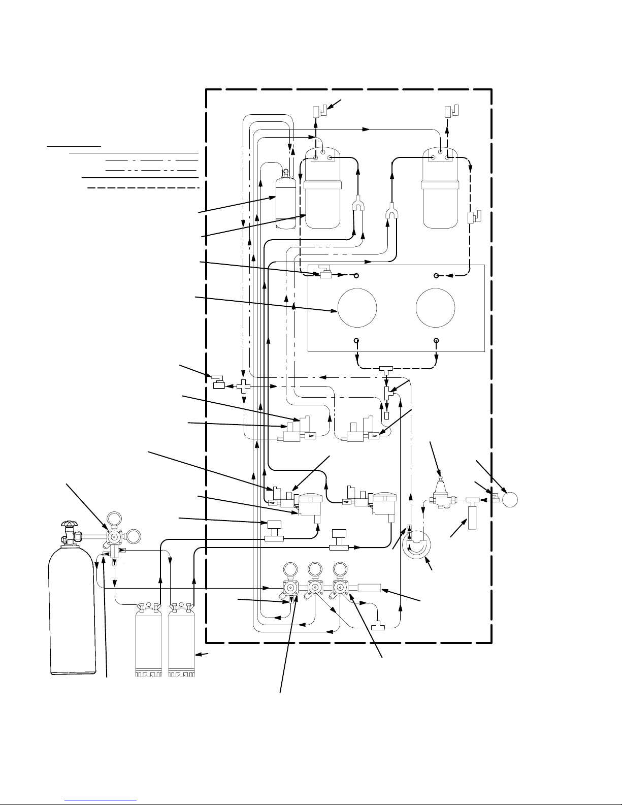
FIGURE 2. FLOW DIAGRAM (TWO-FLAVOR FCB DISPENSER) 6. . . . . . . . . . . .
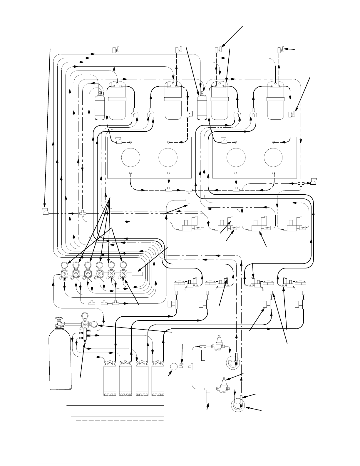
FIGURE 3. FLOW DIAGRAM (FOUR-FLAVOR FCB DISPENSER) 7. . . . . . . . . . .
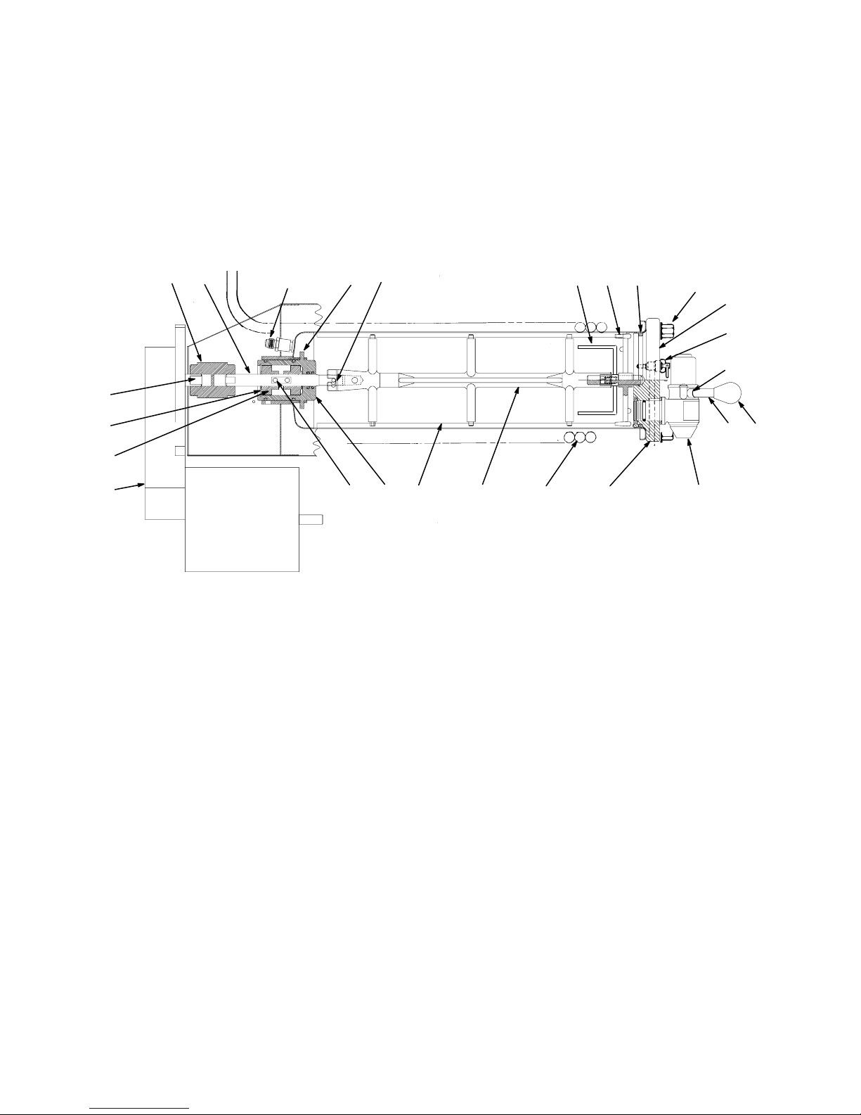
FIGURE 4. FREEZE CYLINDER CUTAWAY VIEW 12. . . . . . . . . . . . . . . . . . . . . . . . .
FIGURE 5. BEATERS AND SCRAPER BLADES INSTALLATION 13. . . . . . . . . . . .
FIGURE 6. OPERATING CONTROLS (FOUR-FLAVOR UNIT) 33. . . . . . . . . . . . . . .
FIGURE 7. UNIT INTERNAL COMPONENTS 34. . . . . . . . . . . . . . . . . . . . . . . . . . . . .
FIGURE 8. SELF-CLOSING DISPENSING VALVE 35. . . . . . . . . . . . . . . . . . . . . . . . .
FIGURE 9. CONTROL PANEL 41. . . . . . . . . . . . . . . . . . . . . . . . . . . . . . . . . . . . . . . . . . .
FIGURE 10. MASTER AND RELAY CIRCUIT BOARD 46. . . . . . . . . . . . . . . . . . . . . .
FIGURE 11. LIQUID CHECK VALVE ASSEMBLY 56. . . . . . . . . . . . . . . . . . . . . . . . . .
FIGURE 12. WATER STRAINER SCREEN AND DOUBLE LIQUID CHECK
VALVE 57. . . . . . . . . . . . . . . . . . . . . . . . . . . . . . . . . . . . . . . . . . . . . . . . . . . . . . . . . . . . . . . .
FIGURE 13. CO2 GAS CHECK VALVE 60. . . . . . . . . . . . . . . . . . . . . . . . . . . . . . . . . . .
FIGURE 14. SERVICING BEATER MOTOR DRIVE SHAFT/SEAL ASSEMBLY 61
FIGURE 15. CARBONATOR LIQUID LEVEL CONTROL SWITCH
ADJUSTMENT 62. . . . . . . . . . . . . . . . . . . . . . . . . . . . . . . . . . . . . . . . . . . . . . . . . . . . . . . .
FIGURE 16. REFRIGERATION FLOW DIAGRAM (AIR-COOLED
REFRIGERATION SYSTEM) 64. . . . . . . . . . . . . . . . . . . . . . . . . . . . . . . . . . . . . . . . . . . .
FIGURE 17. REFRIGERATION FLOW DIAGRAM (WATER-COOLED
REFRIGERATION SYSTEM) 65. . . . . . . . . . . . . . . . . . . . . . . . . . . . . . . . . . . . . . . . . . . .
FIGURE 18. WIRING DIAGRAM 66. . . . . . . . . . . . . . . . . . . . . . . . . . . . . . . . . . . . . . . . .
FIGURE 19. FCB POST-MIX DISPENSER (4-FLAVOR) 74. . . . . . . . . . . . . . . . . . . .
FIGURE 20. FCB POST-MIX DISPENSER (4-FLAVOR) 75. . . . . . . . . . . . . . . . . . . .
FIGURE 21. FCB FLOW DIAGRAM (4-FLAVOR) 76. . . . . . . . . . . . . . . . . . . . . . . . . .
FIGURE 22. FACEPLATE ASSEMBLY 81. . . . . . . . . . . . . . . . . . . . . . . . . . . . . . . . . . . .
FIGURE 23. DISPENSING VALVE ASSEMBLY 82. . . . . . . . . . . . . . . . . . . . . . . . . . . .
FIGURE 24. CO2 REGULATOR ASSEMBLY 83. . . . . . . . . . . . . . . . . . . . . . . . . . . . . .
FIGURE 25. CARBONATOR TANK AND LINKAGE ASSEMBLY 84. . . . . . . . . . . . .
FIGURE 26. PUMP AND MOTOR ASS’Y85. . . . . . . . . . . . . . . . . . . . . . . . . . . . . . . . .
FIGURE 27. DOUBLE CHECK VALVE ASSEMBLY 86. . . . . . . . . . . . . . . . . . . . . . . . .
FIGURE 28. SOLENOID VALVE ASSEMBLY 87. . . . . . . . . . . . . . . . . . . . . . . . . . . . . .
FIGURE 29. DRIP TRAY DRAIN KIT 88. . . . . . . . . . . . . . . . . . . . . . . . . . . . . . . . . . . . .
FIGURE 30. TUBING ASSEMBLY 88. . . . . . . . . . . . . . . . . . . . . . . . . . . . . . . . . . . . . . .
FIGURE 31. TUBING ASSEMBLY 88. . . . . . . . . . . . . . . . . . . . . . . . . . . . . . . . . . . . . . .
FIGURE 32. TUBING ASSEMBLY (CARB WATER) 89. . . . . . . . . . . . . . . . . . . . . . . .
FIGURE 33. TUBING ASSEMBLY (WATER PUMP TO MOTOR) 89. . . . . . . . . . . . .
FIGURE 34. TUBING ASSEMBLY (WATER INLET) 89. . . . . . . . . . . . . . . . . . . . . . . .
FIGURE 35. TUBING ASSEMBLY (SYRUP) 90. . . . . . . . . . . . . . . . . . . . . . . . . . . . . . .
FIGURE 36. TUBING ASSEMBLY (BLENDER TO FREEZE CYLINDER) 90. . . . . .
Page
2813
vi

TABLE OF CONTENTS
LIST OF FIGURES (CONT’D)
FIGURE 37. TUBING ASSEMBLY (WATER SOLENOID TO BLENDER) 91. . . . . .
FIGURE 38. TUBING ASSEMBLY (REGULATOR TO BLENDER) 91. . . . . . . . . . . .
FIGURE 39. BEATER MOTOR DRIVE SHAFT/SEAL ASS’Y92. . . . . . . . . . . . . . . . .
LIST OF TABLES
TABLE 1. DESIGN DATA 2. . . . . . . . . . . . . . . . . . . . . . . . . . . . . . . . . . . . . . . . . . . . . . .
TABLE 2. LOOSE-SHIPPED PARTS 9. . . . . . . . . . . . . . . . . . . . . . . . . . . . . . . . . . . . .
TABLE 4. MAIN MENU SELECTIONS 42. . . . . . . . . . . . . . . . . . . . . . . . . . . . . . . . . . . .
TABLE 5. DIP SWITCH SETTINGS 44. . . . . . . . . . . . . . . . . . . . . . . . . . . . . . . . . . . . . .
TABLE 6. MOTOR SELECT 45. . . . . . . . . . . . . . . . . . . . . . . . . . . . . . . . . . . . . . . . . . . . .
TABLE 7. POINT OF SALE DISPLAY MESSAGES 45. . . . . . . . . . . . . . . . . . . . . . . . .
TABLE 8. “TOTALS” (DISPLAYED CYCLES AND HOURS TOTALS) MENU 49. . .
TABLE 9. DISPLAYED ERROR CONDITIONS 50. . . . . . . . . . . . . . . . . . . . . . . . . . . . .
Page
vii
2813
GENERAL INFORMATION
IMPORTANT: This manual is a guide for installing, operating, and maintaining this equipment. Refer to
Table of Contents for page location of information pertaining to questions that arise during installation,
operation, service and maintenance, or troubleshooting this equipment.
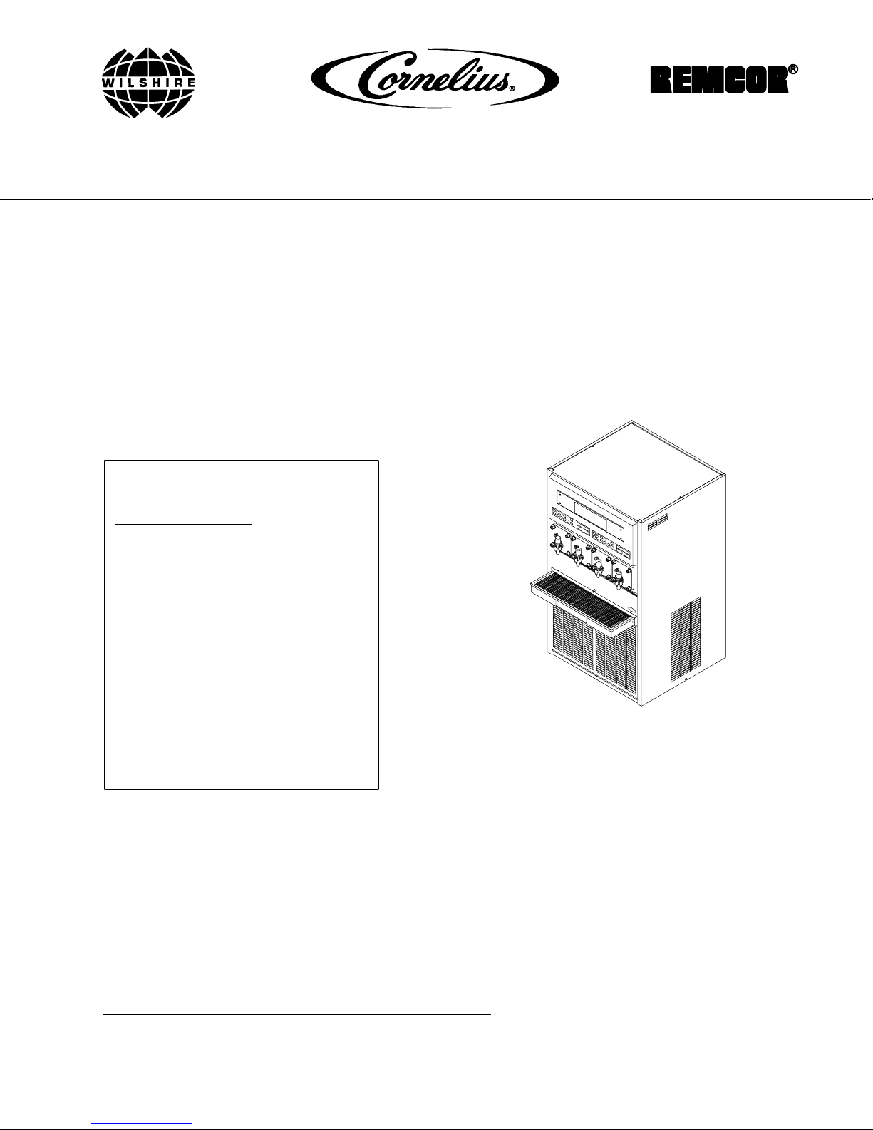
GENERAL DESCRIPTION
This section gives the description, theory of operation, and design data for the Two or Four-Flavor FCB
Post-Mix Dispenser with Hot-Gas Defrost and V3+ Features (hereafter referred to as a Unit).
UNIT DESCRIPTION
TWO-FLAVOR FCB DISPENSER
The Two-Flavor FCB Dispenser (see Figure 2) consists basically of two freeze cylinders, each containing an
internal beater driven by an electric motor, one refrigeration system with a 2-horsepower compressor, one
carbonator that feeds both carbonator-blender tanks, a timer-controlled automatic hot-gas defrost system to
defrost the freeze cylinders, and interconnecting tubing, components, and fittings necessary to regulate,
transfer, and dispense product.
The components are attached to a steel frame and are enclosed in a steel cabinet. The cabinet panels are
easily removed to facilitate installation and service and maintenance. A transparent faceplate, with an integral
relief valve and a removable self-closing dispensing valve, is mounted on front of each freeze cylinder. A
removable drip tray, with cup rest, is located directly below the dispensing valves.
FOUR-FLAVOR FCB DISPENSER
The Four-Flavor FCB Dispenser (see Figure 3 ) consists basically of four freeze cylinders, each containing an
internal beater driven by an electric motor, two refrigeration systems (one for each two freeze cylinders), two
carbonators (one carbonator feeding two carbonator-blender tanks), a timer-controlled automatic hot-gas defrost
system to defrost the freeze cylinders, and interconnecting tubing, components, and fittings necessary to
regulate, transfer, and dispense product.
The components are attached to a steel frame and are enclosed in a steel cabinet. The cabinet panels are
easily removed to facilitate installation and service and maintenance. A transparent faceplate, with an integral
relief valve and a removable self-closing dispensing valve, is mounted on front of each freeze cylinder. A
removable drip tray, with cup rest, is located directly below the dispensing valves.
CAUTION: Before shipping, storing, or relocating Unit, syrup systems must be sanitized
and all sanitizing solution must be purged from syrup systems. All water must also be
purged from plain and carbonated water systems. A freezing ambient environment will
cause residual sanitizing solution or water remaining inside Unit to freeze resulting in damage to
internal components.
1 2813
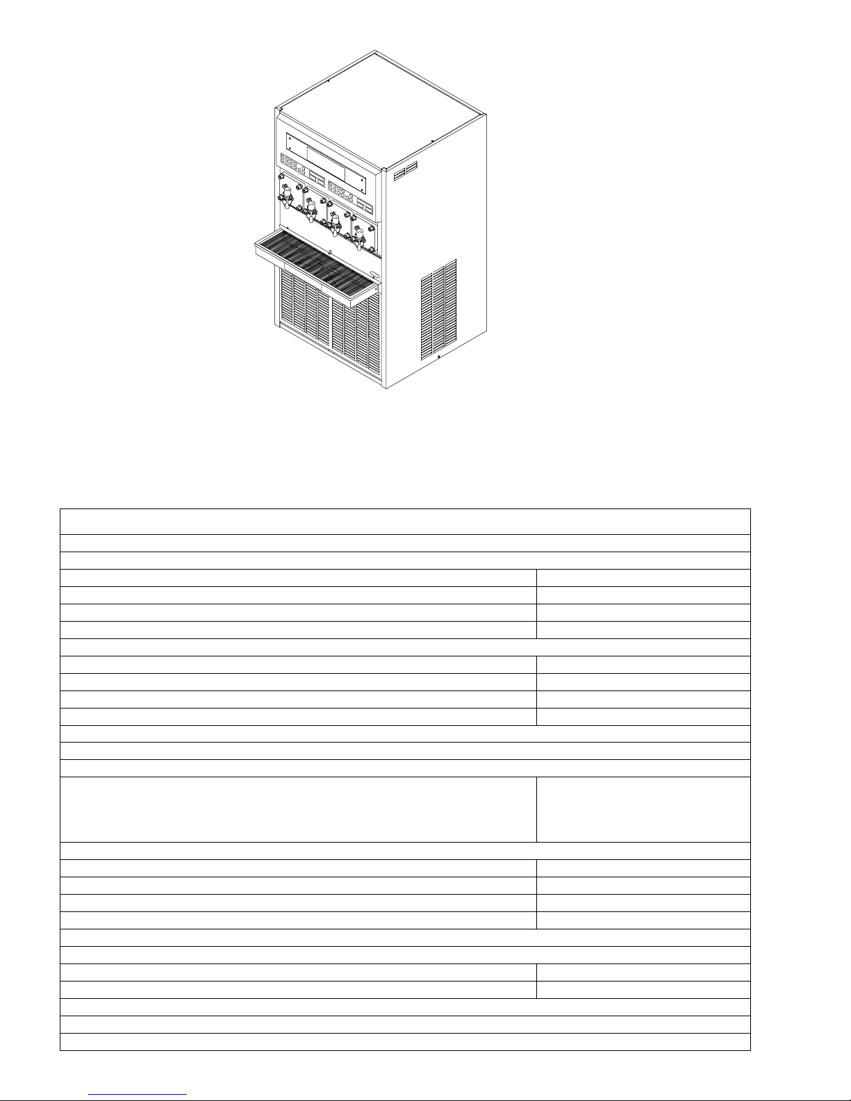
FIGURE 1. FOUR-FLAVOR DISPENSER
Table 1. Design Data
Unit Part Numbers:
60 HZ Units:
Two-Flavor Unit (Air-Cooled) 416220
Two-Flavor Unit (Water-Cooled) 416222
Four-Flavor Unit (Air-Cooled) 416200
Four-Flavor Unit (Water-Cooled) 416202
50 HZ Units:
Two-Flavor Unit (Air-Cooled) 496220
Two-Flavor Unit (Water-Cooled) 496222
Four-Flavor Unit (Air-Cooled) 496200
Four-Flavor Unit (Water-Cooled) 496202
Overall Dimensions:
Two-Flavor Units:
Height
Width
Depth (W/O Drip Tray)
Depth (W/Drip Tray)
60-1/2 inches
19-1/4 inches
32-1/2 inches
38 inches
Four-Flavor Units:
Height 60–1/2 inches
Width 32-1/2 inches
Depth (W/O Drip Tray) 32-1/2 inches
Depth (W/Drip Tray) 38 inches
Shipping Weight (approx)
Two-Flavor Units 466 pounds
Four-Flavor Units 800 pounds
Compressor Horsepower 2 H.P.
22813
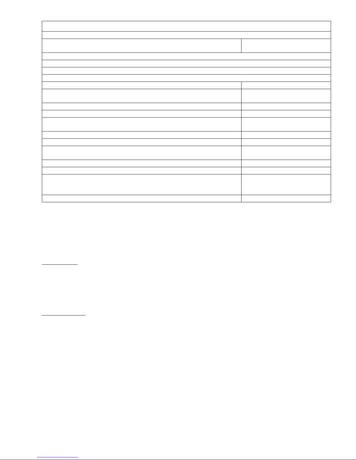
Table 1. Design Data (cont’d)
Refrigeration System:
Refrigerant Type and Charge See Unit
Nameplate
Ambient Operating Temp. 40° F to 100 ° F
Electrical Requirements:
60 HZ Two-Flavor Unit:
Operating Voltage 198-253 VAC, 60 HZ, Single-
Phase
Current Draw 21.2 Amps
50 HZ Two-Flavor Unit:
Operating Voltage 209-253 VAC, 50 HZ, Single-
Phase
Operating Current 22 Amps
60 HZ Four-Flavor Unit:
Operating Voltage 198-253 VAC, 60 HZ, Single-
Phase
Operating Current 40 Amps
50 HZ Four-Flavor Unit:
Operating Voltage 209-253 VAC,
50 HZ, Single-
Phase
Operating Current 40 Amps
REFRIGERATION SYSTEMS
Note: The Two or the Four-Flavor FCB Dispenser (depending upon the model number) refrigeration
system is either “air-cooled” or “water-cooled”.
“Air-Cooled”
The “air-cooled” Two-Flavor FCB Dispenser refrigeration system is equipped with a condenser coil that is cooled
by a condenser coil fan (The Four-Flavor FCB Dispenser is equipped with two condenser coils and two
condenser coil fans).
“Water-Cooled”
The “water-cooled” Two-Flavor FCB Dispenser refrigeration system is equipped with a Refrigeration Cooling
Coil Assembly that contains both refrigerant and plain water cooling coils. Circulating cool plain water through
the cooling coil cools the refrigerant also inside the coil. During installation, City cold plain water is connected to
the FCB Dispenser Refrigeration Cooling Coil water inlet line labeled “COOLING WATER IN”. The water drain
line labeled “COOLING WATER OUT” must be routed to and be connected to a permanent drain.
THEORY OF OPERATION
(see applicable Figure 2 or 3)
IMPORTANT: Before connecting electrical power to Unit, refer to nameplate and note if Unit is to be
operated with 50 or 60 Hz power source.
3 2813

Note: The following paragraph describes the theory of operation for the Two-Flavor FCB Dispenser
(see Figure 2 ). The Four-Flavor FCB Dispenser theory of operation is the same as the Two- Flavor
Dispenser except the Four-Flavor (see Figure 3 ) has two carbonator tanks, four product-blender tanks,
and is connected to four soft drink tanks.
cylinder delivers carbon dioxide (CO2) gas to an adjustable primary CO2 regulator assembly attached to
A CO
2
the cylinder. The primary CO2 regulator assembly in turn delivers CO2 gas to an adjustable secondary CO
regulators inside the Unit and also to the soft drink tanks. CO2 is delivered from the adjustable secondary CO
regulators to the carbonator tank and also to the product-blender tanks inside the Unit. CO2 gas pressure
pushes syrup out of the soft drink tanks through the syrup sold-out switches, through adjustable syrup flow
regulators, through electrically operated syrup solenoid valves, and on to the product blender tanks. At the
same time, plain water passes through the water pressure regulator and is pumped into the carbonator tank by
the water pump. It is carbonated by CO2 gas pressure also entering the tank. Carbonated water is pushed by
CO2 gas pressure from the carbonator tank, through adjustable carbonated water flow regulators, through
electrically operated carbonated water solenoid valves, and on to the product blender tanks. Carbonated water
and syrup enter the tanks properly proportioned (blended) for desired BRIX of dispensed product by adjustment
of the syrup flow regulators. From product blender tanks, product is pushed by the CO2 gas into the freeze
cylinders. The beater in each freeze cylinder is driven by an electric motor. Scraper blades, attached to the
beaters, scrapes product from the cylinder walls as product enters the freeze cylinders and is frozen.
Transparent faceplate, attached to the front of each freeze cylinder, includes a self-closing dispensing valve and
a spring-loaded relief valve that protects freeze cylinder from accidental over pressure. The relief valve is also
used to bleed CO2 gas pressure from the freeze cylinder to atmosphere when filling the cylinder with product.
Electronic sensing on each freeze cylinder motor provides a means of adjusting viscosity (consistency) of the
dispensed product to suit customer preference.
2
2
DEFROST SYSTEMS
The Unit is equipped with both manual and automatic hot-gas defrost systems. The automatic defrost system
may be programmed into the Unit to occur up to nine different times a day with a minimum of two hours
between defrost time settings or the system may be completely turned off.
MANUAL DEFROST SYSTEM
Two-Flavor FCB Dispenser
The Manual hot-gas defrost system may be activated at any time by pressing the ‘‘DEFROST’’ switch on front
of the Unit. Refrigeration compressor will operate for a short time, then both freeze cylinders will go into defrost
for approximately 60-seconds. At the end of the manual defrost cycle, the Unit will return to normal operation.
Manual defrost may be cancelled at any time by pressing the ‘‘CANCEL DEFROST’’ switch.
Four-Flavor FCB Dispenser
The Manual hot-gas defrost system may be activated at any time by pressing the “DEFROST” switch on front of
the Unit. Refrigeration compressor will operate for a short time, then both No. 1 and No.11 or No. 2 and No. 22
(depending upon which “DEFROST” switch was pressed) freeze cylinder only will go into defrost cycle for one
minute. At the end of the manual defrost cycle, Unit will return to normal operation. Manual defrost may be
cancelled at any time by pressing the “CANCEL DEFROST” switch.
AUTOMATIC DEFROST SYSTEM
Note: The following paragraph describes the Automatic Hot-Gas Defrost system operation for the
Two-Flavor FCB Dispenser No. 1 and No. 2 freeze cylinders. This paragraph also describes the
Automatic Hot-Gas Defrost system operation for the Four-Flavor FCB Dispenser No. 11 and No. 22
freeze cylinders which is identical to the No. 1 and No. 2 freeze cylinders.
42813

The automatic hot-gas defrost system may be programmed into the Unit to occur up to nine different times a
day with a minimum of two hours between defrost settings. At the start of each automatic defrost cycle,
refrigeration compressor will operate for 30-seconds to pump freon out of the freeze cylinders evaporator coils.
After freon has been pumped out of the freeze cylinders evaporator coils, No. 1 freeze cylinder only will go into
defrost cycle for approximately 7 minutes, then will return to normal operation. This ends the automatic defrost
cycle of No. 1 freeze cylinder. No. 2 freeze cylinder will defrost 30-minutes after the start of No.1 freeze cylinder.
The next automatic defrost cycle will occur according to the time programmed into the Unit. Automatic defrost
may be cancelled at any time by pressing the ‘‘CANCEL DEFROST’’ switch.
‘‘SLEEP’’ (SLEEP TIME)
Note: The following paragraph describes “SLEEP” (SLEEP TIME) operation for the Two-Flavor and the
Four-Flavor FCB Dispensers No. 1 and No. 2 freeze cylinders. The “SLEEP” (SLEEP TIME) operation for
the Four-Flavor FCB Dispenser No. 11 and No. 22 freeze cylinders is identical to the No. 1 and No. 2
freeze cylinders.
‘‘SLEEP’’ (SLEEP TIME) may be programmed into Unit to allow Unit to go into sleep time (Unit shut down,
freeze cylinders beaters and refrigeration systems not operating). At start of sleep time, refrigeration
compressor will operate for 30-seconds to pump freon out of freeze cylinders evaporator coils, then No.1 freeze
cylinder will go into defrost cycle for 60-seconds. After No.1 freeze cylinder has defrosted, No. 2 freeze cylinder
will go into defrost cycle for 60-seconds. At end of No. 2 freeze cylinder defrost, Unit will shut down and go into
sleep time.
‘‘WAKE UP’’ (WAKE UP TIME)
‘‘WAKE UP’’ (WAKE UP TIME) may be programmed into the Unit to allow Unit to resume normal operation at a
desired time. When programmed wake up time is reached, an alarm will sound for a short duration, then Unit
will resume normal operation.
NOTE: Automatic defrost, sleep time, and wake up time may be used in any combination together or
separately.
5 2813
*WATER PRESSURE REGULATOR IS
FACT ORY ADJUSTED TO 45 PSI AND
SHOULD NOT BE READJUSTED.
**SYRUP SOLD–OUT SWITCHES ARE
FACTORY ADJUSTED AND SHOULD
NOT BE READJUSTED.
LINE LEGEND
CO
2
PLAIN WATER
CARB WATER
SYRUP
PRODUCT
CARBONATOR
TANK
PRODUCT BLENDER
TANK(2)
PRODUCT SHUTOFF
VALVE(2)
FREEZE
CYLINDER(2)
PRODUCT SAMPLE
VALVE(2)
CARBONATED WATER
VOLUME SAMPLE VALVE
CARBONATED WATER
SOLENOID VALVE(2)
CARBONATED WATER
FLOW REGULATOR(2)
SYRUP SOLENOID
VALVE(2)
PRIMARY CO
REGULATOR ASS’Y
CO
2
CYLINDER
2
SYRUP SOLD–OUT
FLOAT SWITCH(2)
**SYRUP SOLD–OUT
SWITCH
CO
2
CHECK
VALVE
SYRUP FLOW
REGULATOR(2)
DOUBLE
LIQUID
CHECK
VALVE
FREEZE CYLINDER
OVERFLOW TUBE
LIQUID CHECK
VALVE(2)
*WATER PRESSURE
REGULATOR
PLAIN WATER
SOURCE
SHUTOFF
VALVE
WATER
PRESSURE
SWITCH
CARBONATOR
WATER PUMP
CO
2
PRESSURE
SWITCH
CO
CHECK
2
VALVE(3)
FIGURE 2. FLOW DIAGRAM (TWO-FLAVOR FCB DISPENSER)
SOFT DRINK
TANK(2)
SECONDARY CO2 REGULATORS
TO PRODUCT BLENDER
TANKS (60–PSI GAGE) (2)
SECONDARY CO2 REGULATOR
TO CARBONATOR TANK
(100–PSI GAGE)
62813
*WATER PRESSURE REGULATORS
ARE FACTORY ADJUSTED TO 45-PSI
AND SHOULD NOT BE READJUSTED.
CARBONATED WATER
VOLUME SAMPLE VALVE
**SYRUP SOLD-OUT SWITCHES
ARE FACTORY ADJUSTED AND
SHOULD NOT BE READJUSTED.
CARBONATOR
TANK (2)
PRODUCT SAMPLE
VALVE (4))
PRODUCT BLENDER
TANK (4)
PRODUCT
SHUTOFF
VALVE (4)
CARBONATED
WATER
SAMPLE VALVE (2)
1
FREEZE
CYLINDER (4)
SECONDARY CO2 REGULATORS
TO PRODUCT BLENDER
TANKS (60-PSI GAGES)
FREEZE CYLINDERS
OVERFLOW TUBE
SECONDARY CO2 REGULATORS
TO CARBONATOR TANKS
(100-PSI GAGES)
2
CARBONATED WATER
SOLENOID (4)
CO2 PRESSURE
SWITCH
11
LIQUID CHECK
VALVE (4)
22
CARBONATED WATER
FLOW REGULATOR (4)
SYRUP FLOW
REGULATOR (4)
CO
2
CYLINDER
CHECK VALVE (5)
LINE LEGEND
CO
2
PLAIN WATER
CARB WATER
SYRUP
PRODUCT
CO2 GAS
121122
SYRUP TANK (4)
FIGURE 3. FLOW DIAGRAM (FOUR-FLAVOR FCB DISPENSER)
CO2 GAS
CHECK VALVE (2)
SYRUP
SOLENOID (4)
PRIMARY
CO2 REGULATOR
SHUTOFF VALVE
PLAIN WATER
SOURCE
WATER PRESSURE
SWITCH
(2)
**SYRUP SOLD-OUT
SWITCH (4)
*WATER PRESSURE
REGULATOR (2)
DOUBLE LIQUID
CHECK VALVE (2)
CARBONATOR
WATER PUMP (2)
LIQUID CHECK
VALVE (4)
SYRUP FLOAT
SWITCH (4)
7 2813

THIS PAGE LEFT BLANK INTENTIONALLY
82813
INSTALLATION
This section covers unpacking and inspection, installing LOOSE-SHIPPED PARTS, selecting location, installing
Unit, preparing for operation, and operation.
UNPACKING AND INSPECTION
(see Figure 6)
NOTE: The Unit was thoroughly inspected before leaving the factory and the carrier has accepted and
signed for it. Any damage or irregularities should be noted at time of delivery (or not later than 15 days
from date of delivery) and immediately reported to the delivering carrier. Request a written inspection
report from Claims Inspector to substantiate any necessary claim. File claim with the delivering carrier,
not with IMI Cornelius Inc.
1. After Unit has been unpacked, remove shipping tape and other packing material.
2. Remove Unit sides, top and back panels as instructed.
3. Remove shipping bolts that secure Unit to skid, then remove skid.
4. Unpack LOOSE-SHIPPED PARTS. Make sure all items are present and in good condition.
IDENTIFICATION OF LOOSE-SHIPPED PARTS
1. TAPERED GASKETS, WHITE (item 1 ) are used to seal connections when connecting Unit product inlet
lines to product tanks and connecting Unit CO2 inlet line to CO2 source.
2. SPANNER WRENCH, DISPENSING VALVE (item 2) is used to remove shank nuts securing dispensing
valves to faceplates.
3. CLEANING BRUSH (item 3) is used to clean faceplate relief valves passages.
Table 2. Loose-Shipped Parts
Item
No. Part No. Name
1 178025-100 Tapered Gasket, White 4 5
2 322859 Spanner Wrench, Dispensing Valve 1 1
3 325216 Cleaning Brush 1 1
4 311304 Tapered Gasket, Black 3 5
5 325982
325992
6 319941 Thread Cutting Screw, Hex HD, No. 8-32 by 3/8 in. Long 4 4
Cup Rest
Cup Rest
Qty.
2-Fl
1
x
Qty.
4-Fl
x
1
7 325986 Drip Tray Support 2 2
8 325991 Frame, Drip Tray
Frame, Drip Tray
9 325990-039
325983-039
Drip Tray
Drip Tray
x
1
x
1
9
1
x
1
x
2813

Table 3. Loose-Shipped Parts (cont’d)
Item
No.
10 326002 Kit, Drip Tray Drain Hose 1 1
11 2899 Wrench, Rear Seal Housing 1 1
12 3810 Tool, Drive/Coupler Adjustment Gauge 1 1
13 325018 Caster Kit, 4–inch diameter casters 1 1
4. TAPERED GASKET, BLACK (item 4) is used to seal connection when connecting plain water source line to
5. DRIP TRAY SUPPORTS (item 7) to be installed on front of Unit and secured with THREAD CUTTING
6. CUP REST (item 5 ) to be installed in DRIP TRAY (item 9 ), then drip tray to be installed in FRAME, DRIP
7. WRENCH, REAR SEAL HOUSING (item 11) used to remove the drive shaft/seal assembly from inside the
8. TOOL, DRIVE/COUPLER ADJUSTMENT GAUGE (item 12) is used for servicing the beater motor drive
9. DRIP TRAY DRAIN HOSE KIT (item 10) is to be installed on the drip tray as described in instructions
Part No. Name
∗ Νumbers in parentheses are in reference to items in Figure 4.
Unit water inlet line.
SCREWS (item 6 ).
TRAY (item 8 ). Assembled drip tray assembly then to be installed on drip tray supports on front of the Unit.
freeze cylinder.
shaft/seal assembly (see Figure 14).
provided with the Kit.
Qty.
2-Fl
Qty.
4-Fl
10. CASTER KIT (item 13) to be installed on the Unit as instructed in Installation Instructions provided with the
kit.
ELECTRICAL POWER REQUIREMENTS
IMPORTANT: Before connecting electrical power to Unit, refer to nameplate and Note if Unit is to be
operated with 50 or 60 Hz power source.
TWO-FLAVOR FCB DISPENSER
A properly grounded 198-253 VAC, 60 Hz or 209-253 VAC, 50 Hz single-phase electrical circuit with a 30-amp
minimum-rated disconnect switch (not provided) fused at 30-amps (slow-blow) or circuit connected through an
equivalent HACR circuit breaker must be available to the Unit. ALL WIRING MUST CONFORM TO NATIONAL
AND LOCAL CODES. MAKE SURE UNIT IS PROPERLY GROUNDED.
FOUR-FLAVOR FCB DISPENSER
A properly grounded 198-253 VAC, 50Hz or 209-253 VAC, 50 Hz single-phase electrical circuit with a 50-amp
minimum-rated disconnect switch (not provided) fused at 50-amps (slow-blow) must be available to the Unit.
SELECTING LOCATION
IMPORTANT: Unit operating ambient temperature MUST NOT EXCEED 100° F. Operating ambient in
excess of 100° F will automatically void the factory warranty and will eventually result in Unit failure.
Several means are available to achieve proper ambient temperature and air circulation around the Unit
which are wall air intake grilles and ceiling exhaust fans, air conditioning, etc. Consult local codes.
Locate Unit so the following requirements are satisfied.
102813

1. Close to a plain water inlet supply line with a minimum pressure of 12 psig.
NOTE: “AIR-COOLED FCB DISPENSER
The “air-cooled” FCB Dispenser refrigeration system is equipped with a condenser coil that is cooled
by a condenser coil fan. Circulating air, required to cool the refrigeration system’s condenser coil, is
drawn in through grille on front and exhausted out through sides and back of Unit. Restricting air
circulation through the Unit will decrease its cooling efficiency.
2. When installing Unit, do not allow obstruction to block grille on front which will block off air intake to inside
of Unit. If installation dictates only one side or back being unobstructed, allow 18-inches clearance between
Unit and obstruction. If both sides or one side and back are unobstructed, allow 12-inches clearance. If
both sides and back are unobstructed, allow 6-inches clearance.
INSTALLING UNIT
PLACING UNIT IN OPERATING LOCATION
1. Place Unit in operating location meeting requirements of SELECTING LOCATION.
IMPORTANT NOTICE
The FCB Dispensers manufactured prior to the models documented in this manual were elevated in the front
(dispensing valve side) 1/4 to 3/8-inch higher than the back when placing the Unit in operating position to
eliminate gas pockets being trapped inside the freeze cylinders. Due to a re-design of the foam pack in the
models documented in this manual, elevating the front of the Dispenser is no longer required. The Dispenser
must be leveled at time of placing in operating location.
Note: An alternate to sealing the Unit base to the floor would be to install the 4-inch Caster Kit
provided with the Unit. Refer to installation Instructions provided with the kit for installation
instructions. .
2. After Unit has been placed in operating location, make sure it is sitting in a level position.
3. To comply with National Sanitation Foundation (NSF) requirements, Unit installed with base contacting floor
must have base sealed to floor with Dow Corning RTV 731 or equivalent.
INSTALLING DRIP TRAY SUPPORTS, DRIP TRAY, AND CUP REST
1. Install DRIP TRAY SUPPORTS (item 7) on panel above lower front access panel on front of Unit. Secure
supports to panel with THREAD CUTTING SCREWS (item 6).
2. Place DRIP TRAY (item 9) in FRAME, DRIP TRAY (item 8), then slide frame up on drip tray supports on
front of Unit.
INSTALLING DRIP TRAY DRAIN HOSE KIT
Install DRIP TRAY DRAIN HOSE KIT (item 10) on Unit as instructed in Installation Instructions provided with
the Kit.
11
2813
12
2813
1 Product Inlet Fitting
2 Scraper Blade (2)
3 Evaporator Coil
4 Relief Valve Port
5 O-Ring
6 Flatwasher (4)
7 Hex Nut (4)
8 Faceplate
9 Relief Valve
10 Valve Lever
11 Knob
12 Dispensing Valve
13 Beater
14 Allen Head Setscrew
15 Beater Shaft Coupling
16 Drive Pin
17 Bearing Housing Locking T ab (4)
18 Bearing Retainer
19 Beater Motor Drive Shaft
20 Beater Drive Motor
21 Drive Shaft Assembly
22 Viscosity Sensor
23 Spinner
24 Spring
25 Shaft Release
26 Bearing
27 Bearing Housing
1
23
4
56
7
8
9
10 11
121314
15 16
17
18
19
20
21 22 23
24
25
26
27
FIGURE 4. FREEZE CYLINDER CUTAWAY VIEW
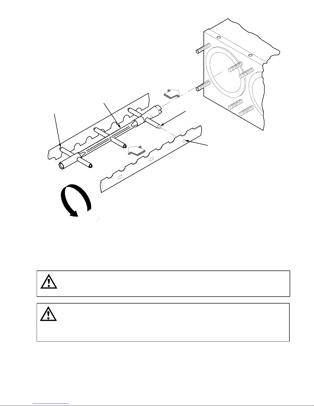
BEATER
KEY ON END
OF POST
KEY ON END
OF POST
KEY SLOT
ON BLADE
SCRAPER BLADES MUST BE MOUNTED TO THE
BEATER BODY AS SHOWN USING THE PERFORATED
EDGE AS THE LEADING EDGE. LINE UP KEY ON END
OF POSTS WITH KEY SLOT IN SCRAPER BLADES.
FIGURE 5. BEATERS AND SCRAPER BLADES INSTALLATION
INSTALLING PRIMARY CO2 REGULATOR ASSEMBLY ON CO2 CYLINDER
(see applicable Figure 2 or 3)
WARNING: To avoid personal injury and/or property damage, always secure CO2 cylinder in
upright position with a safety chain to prevent it from falling over. Should the valve become
accidentally damaged or broken off, CO2 cylinder can cause serious personal injury.
WARNING: CO2 displaces oxygen. Strict attention must be observed in the prevention of
CO2 (carbon dioxide) gas leaks in the entire CO2 and soft drink system. If a CO2 gas leak is
suspected, particularly in a small area, immediately ventilate the contaminated area before
attempting to repair the leak. Personnel exposed to high concentration of CO2 gas will experience
tremors which are followed rapidly by loss of consciousness and suffocation.
1. Unscrew protector cap (with chain attached) from CO2 cylinder valve. Open CO2 cylinder valve slightly
counterclockwise to blow any dirt or dust from outlet fitting before installing primary CO2 regulator, then
close valve.
2. Remove shipping plug from primary CO2 regulator assembly coupling nut, and make sure gasket is in
place inside nut. Install regulator assembly on CO2 cylinder so gages can be easily read, then tighten
coupling nut. DO NOT OPEN CO2 CYLINDER VALVE AT THIS TIME.
13 2813

CONNECTING SOFT DRINK TANKS CO2 LINES TO PRIMARY CO2 REGULATOR
ASSEMBLY
(see applicable Figure 2 or 3)
1. Connect soft drink tanks CO
Figure 2 or 3.
2. Install gas quick disconnects on ends of soft drink tanks CO
TANKS AT THIS TIME.
lines to primary CO2 regulator manifold assembly as shown in applicable
2
lines. DO NOT CONNECT CO2 LINES TO
2
PREPARING UNIT SYRUP INLET LINES FOR CONNECTION TO SOFT DRINK TANKS
(see applicable Figure 2 or 3 )
1. Route Unit syrup inlet lines, labeled No. 1 and No. 2 (two-flavor Units) or No.1, No. 2, No.11, and No. 22
(four-flavor Units) out through hole provided in the Unit base to the soft drink tanks location.
2. Install liquid disconnects on ends of Unit syrup inlet lines. DO NOT CONNECT SYRUP LINES TO TANKS
AT THIS TIME.
CONNECTING CITY PLAIN WATER Source LINE (S) TO UNIT
Note: All of the Units require connection to a City plain water source line with a minimum water
pressure of 12 psig to be connected to the Unit plain water inlet line which provides plain water to the
Unit post-mix system. The Units equipped with water-cooled refrigeration systems also require a City
plain water source line to be connected to the refrigeration cooling coil(s) plain water inlet lines.
Proceed as follows to connect a City plain water source line(s) to the Unit.
Connecting City Plain Water Source Line to Unit Post-Mix System.
(see applicable Figure 2 or 3 )
NOTE: IMI Cornelius Inc. recommends that a water shutoff valve and water filter be installed in the City
plain water source line (see applicable Figure 2 or 3 ) that provides plain water to the Dispenser
post-mix system. A Cornelius Water Filter (P/N 313860000) and Quick Disconnect Set (P/N 313867000)
are recommended.
1. Before connecting the City plain water source line to the Unit that provides plain water to the post-mix
system, open shutoff valve in City plain water source line for a period of time to flush out any metal
shavings.
2. Route Unit plain water inlet line out through hole in bottom of Unit base.
NOTE: Carbonator plain water inlet adjustable water pressure regulator (see Figure 12) is factory
adjusted to 45 psi and should not be readjusted.
3. Connect Unit plain water inlet line to the City plain water source line (12 psi minimum pressure). Seal
connection with TAPERED GASKET, BLACK (item 4). DO NOT OPEN THE CITY PLAIN WATER
SOURCE LINE SHUTOFF VALVE AT THIS TIME.
Connecting City Plain Water Source Line(s) to Unit With Water-Cooled Refrigeration System.
(See Figure 17)
Note: The water-cooled Two-Flavor FCB Post-Mix Dispenser has one water-cooled refrigeration system
which requires connection of a City plain water source line to its refrigeration cooling coil plain water
inlet line. The water-cooled Four-Flavor FCB Post-Mix Dispenser has two refrigeration systems and
requires a City plain water source line to be connected to its two refrigeration cooling coils plain water
inlet lines. THE CITY PLAIN WATER SOURCE LINE MUST INCLUDE A WATER SHUTOFF VALVE.
Proceed as follows to connect the City plain water source line to the Dispensers refrigeration cooling
coil(s) plain water inlet line(s).
142813
1. Route the refrigeration cooling coil(s) plain water inlet line(s) labeled “COOLING WATER IN” and line(s)
labeled “ COOLING WATER OUT” out through hole in bottom of the Unit base.
2. Connect the refrigeration cooling coil(s) plain water inlet line(s) labeled “COOLING WATER IN” to the City
plain water inlet line. Seal connection(s) with TAPERED GASKET(S), BLACK (item 4).
3. Route the line(s) labeled “COOLING WATER OUT” to a permanent drain and connect. Seal connection(s)
with TAPERED GASKET(S), BLACK (item 4).
CONNECTING ELECTRICAL POWER CIRCUIT TO UNIT
(see Figure 18 )
WARNING: Make sure disconnect switch (not provided) or equivalent HACR circuit breaker
is in ‘‘OFF’’ position.
60 HZ Unit.
IMPORTANT: Power circuit voltage across L1 and L2 terminals on the contactor inside the lower control
box, with refrigeration compressor operating, must be in the range of 198-253 VAC, 60Hz single-phase
for proper operation. Use No. 10 AWG copper wire, or larger, depending upon line length, in suitable
conduit or BX sheath. POWER CIRCUIT TO UNIT MUST BE MADE UP OF COPPER CONDUCTORS AND
ALL WIRING MUST CONFORM TO NATIONAL AND LOCAL CODES.
50 HZ Unit.
IMPORTANT: Power circuit voltage across L1 and L2 terminals on the contactor inside the lower control
box, with refrigeration compressor operating, must be in the operating range of 209-253 VAC, 50Hz
single-phase for proper operation.
1. Remove lower control box (located on lower-right side facing front of Unit) cover for access to contactor L
and L
terminals.
2
WARNING: This Unit must be electrically grounded to avoid possible fatal electrical shock
or serious injury to the operator. A green screw, with lock washer, is provided inside
control box to connect power circuit ground wire electrically grounding the Unit.
2. Connect electrical power from a 30-amp (for a two-flavor Unit) or 50-amp (for a four-flavor Unit)
minimum-rated disconnect switch (not provided) fused at 30-amps slow-blow (for a two-flavor Unit) or
50-amps slow-blow (for a four-flavor Unit) or through an equivalent HACR circuit breaker to L1 and L
2
terminals on the contactor inside the control box. MAKE SURE GROUND WIRE IS CONNECTED TO
GREEN GROUND SCREW INSIDE CONTROL BOX.
3. Install lower control box cover and secure with screws.
1
15 2813

PREPARATION FOR OPERATION
TURNING ON ELECTRICAL POWER TO UNIT
Turn on electrical power to Unit. Operational status of Unit is now being displayed as fault messages on control
panel message display. The following fault messages will be continuously displayed at 2-second intervals until
necessary operation requirements are satisfied.
‘‘OFF 1’’ (Beater Motor No. 1 not operating)
‘‘OFF 2’’ (Beater Motor No. 2 not operating)
O OUT’’ (No water supply to Unit)
‘‘H
2
‘‘CO2 OUT’’ (No CO2 gas supply to Unit)
‘‘SYRUP 1’’ (No syrup supply to Unit No. 1 syrup system)
‘‘SYRUP 2’’ (No syrup supply to Unit No. 2 syrup system)
TURNING ON CO2 SUPPLY TO UNIT
1. Open CO2 cylinder valve slightly to allow lines to slowly fill with gas, then open valve fully to back seat
valve. Back-seating valve prevents leakage around valve shaft.
IMPORTANT: If bag-in-box syrup supply system will be connected to Unit instead of soft drink tanks,
primary CO2 regulator (see applicable Figure 2 or 3) must be adjusted to no less than 80-PSI.
2. For soft drink tanks installation (see applicable Figure 2 or 3), adjust primary CO2 regulator by turning
regulator adjusting screw to the right (clockwise) until regulator pressure reads 80 to 100 psig. OUT OF
CO2 warning light on control panel message display should have gone out.
3. Pull up on product blender tanks relief valves to purge air from tanks.
4. Remove Unit lower stainless steel access panel as instructed for access to carbonator secondary CO
regulators (see applicable Figure 2 or 3 and 7).
5. Check product blender tanks secondary CO2 regulators with 60 psi gages for pressure setting which
should be set at 25 to 30 psi for best textured product. If further adjustment is necessary, adjust as
instructed.
IMPORTANT: Carbonator(s) secondary CO2 regulator(s) must be adjusted 25 psi higher or more above
product blender tanks secondary CO2 regulators pressure settings. Carbonated water and syrup
pressures must be able to overcome and vent product blender tanks head pressures while tanks are
filling with carbonated water and syrup. Carbonator(s) tank(s) secondary CO2 regulator(s) not adjusted
high enough will cause decreased flow of carbonated water into blender tanks which will increase brix
of dispensed product.
6. Adjust carbonator(s) secondary CO2 regulator(s), with 100 psi gage(s), by turning regulator(s) adjusting
screw(s) to the right (clockwise) until gage(s) reads 50 to 60 psi.
7. Pull up on carbonator(s) tank(s) relief valve(s) plastic cover(s) to purge air from tank(s).
2
TURNING ON CITY PLAIN WATER SOURCE LINE TO UNIT
City Plain Water Source Line Connected to Unit Post-Mix System (Water-Cooled and Air-Cooled Refrigeration
Units).
Open shutoff valve in City plain water line connected to the Unit Post-mix system. Check for water leaks and
tighten or repair if evident. ‘‘H2O OUT’’ fault message should have gone out but ‘‘SYRUP 1’’, and ‘‘SYRUP 2’’
fault messages will continue to be displayed.
City Plain Water Source Line Connected to Unit With Water-Cooled Refrigeration System.
Open shutoff valve in City water line connected to the refrigeration cooling coil (two-flavor Unit) or two
refrigeration cooling coils (four-flavor Unit). Check for water leaks and tighten or repair if evident.
162813

CONNECTING SOFT DRINK TANKS TO UNIT SYRUP SYSTEMS
IMPORTANT: Product shutoff valves, located in lines leading from product blender tanks to freeze
cylinders (see applicable Figure 2 or 3 and 7), must be closed at this time. Closing valves prevents
product from filling freeze cylinders while checking Brix of product in product blender tanks.
1. Close product shutoff valves, located in lines leading from product blender tanks to freeze cylinders, to
prevent product from entering cylinders.
IMPORTANT: The following CO2 and liquid disconnects disconnecting and connecting procedure for
soft drink tank replacement or filling soft drink tank in place must be performed in order as follows:
To disconnect soft drink tank from Unit syrup system.
A. Disconnect liquid disconnect from soft drink tank. NOTE - Disconnecting liquid quick disconnect from
soft drink tank first prevents syrup from backflowing through Unit syrup flow regulator, which may alter
regulator adjustment.
B. Second, disconnect CO2 quick disconnect from soft drink tank.
NOTE: The Two-flavor Unit is equipped with one control panel (see Figure 9) which controls operation
of the two freeze cylinders and the four-flavor Unit is equipped with two control panels, each control
panel controlling two of the four freeze cylinders. The Unit control panel is equipped with a hidden
‘‘SECURITY SWITCH’’ located between ‘‘FILL 1’’ and ‘‘ERROR RESET’’ control switches (see Figure
NO TAG). Pressing in and holding the ‘‘SECURITY SWITCH’’ for 10-seconds deactivates the control
switches to prevent any tampering with the Unit’s normal operation. To reactivate the control switches,
press in and hold the ‘‘SECURITY SWITCH’’ for 10-seconds.
2. Pressurize soft drink tanks containing syrup, then connect tanks to Unit syrup systems. ‘‘OFF 1’’, ‘‘OFF 2’’,
‘‘SYRUP 1’’, and ‘‘SYRUP 2’’ fault messages will continue to be displayed.
ADJUSTING BRIX (WATER-TO-SYRUP) ‘‘RATIO’’ OF DISPENSED PRODUCT
The following steps 1 through 9 are instructions for adjusting Brix (Water-to-Syrup ‘‘Ratio’’ (mixture) of
dispensed product on one of the two (two-flavor Unit) or one of the four (four-flavor Unit) systems.
Note: The adjustable carbonated water flow regulators (see applicable Figure 2 or 3 and 12 ) located in
their respective systems, control carbonated water flow rate to the product blender tanks. The water
flow regulators are factory adjusted at 1.3 0.05 oz/sec. and should not normally require adjustment.
If adjustment is necessary, adjust as instructed.
1. Press ‘‘FILL 1’’ switch to fill No. 1 syrup system sold-out float. ‘‘SYRUP 1’’ fault message will go out and
‘‘FILL 1’’ fault message will come on. ‘‘OFF 1’’, ‘‘OFF 2’’, and ‘‘SYRUP 2’’ fault messages will continue to be
displayed.
2. Press ‘‘AUTO BLEND 1’’ switch to fill No. 1 system product blender tank with product. ‘‘FILL 1’’ fault
message will go out when ‘‘AUTO BLEND 1’’ switch is pressed. When product blender tank is full, press
‘‘FILL 1’’ switch to prevent more product from entering tank. ‘‘OFF 1’’, ‘‘OFF 2’’, and ‘‘SYRUP 2’’ fault
messages will continue to be displayed.
3. Open No. 1 product blender tank product sample valve (see applicable Figure 2 or 3 and 7) and take
sample (approximately 6-ounces) of product in a cup or glass.
NOTE: Temperature compensated hand-type refractometers (P/N 511004000) are available from the
Cornelius Company.
4. Check product Brix with a temperature compensated hand-type refractometer. Brix should read 13 ± 1. If
Brix is not within tolerance, adjust white syrup flow regulator for No. 1 syrup system as follows:
Turn regulator adjusting screw to the left (counterclockwise) no more than 1/8-turn at a time to reduce
syrup flow rate or turn screw to the right (clockwise) no more than 1/8-turn to increase flow rate.
5. Place container under No. 1 product sample valve. Open valve to purge product out of product blender
tank, line, and valve, then close valve. ‘‘OFF 1’’, ‘‘OFF 2’’, and ‘‘SYRUP 2’’ will continue to be displayed.
17 2813

6. Press ‘‘AUTO BLEND 1’’ switch to run new batch of product into product blender tank. When product
blender tank is full, press ‘‘FILL 1’’ switch to prevent more product from entering product blender tank.
‘‘OFF 1’’, ‘‘OFF 2’’, and ‘‘SYRUP 2’’ fault messages will continue to be displayed.
7. Repeat steps 3 and 4 preceding to check product sample for Brix.
8. Repeat steps 5 through 7 preceding until proper BRIX adjustment is achieved.
9. Repeat steps 1 through 8 preceding to adjust BRIX of dispensed product on No. 2 system. After
completing Brix adjustment on No. 2 system, only the ‘‘OFF 1’’ and ‘‘OFF 2’’ fault messages should
continue to be displayed.
10. Repeat steps 1 through 9 preceding to adjust Brix (Water-to-Syrup) ratio (mixture) of dispensed product on
remaining systems.
NOTE: Syrup systems may be sanitized at this time as instructed.
FILLING FREEZE CYLINDERS WITH PRODUCT
1. Open product shutoff valves, located in lines leading from product blender tanks to freeze cylinders.
2. Press ‘‘AUTO BLEND 1’’ and ‘‘AUTO BLEND 2’’ switches to begin filling freeze cylinders. Open freeze
cylinders faceplates relief valves to bleed air from cylinders while filling with product, then close valves. Do
not relieve freeze cylinder pressure too fast or product will foam excessively in cylinder and lose
carbonation.
ADJUSTING “WATER-COOLED” UNITS REFRIGERATION SYSTEM(S) VARIABLE
WATER REGULATOR(S)
IMPORTANT NOTICE
Water-cooled Two and Four-Flavor Dispensers.
Water flow rate through the refrigeration cooling coil varies due to pressure change on the high side of
the refrigeration compressor which influences opening and closing of the variable water regulator (see
Figure ).The variable water regulator must be adjusted to maintain 200-psi high-side pressure.
Adjust the variable water regulator (see Figure 17) to maintain 200-psi refrigeration high-side pressure as
instructed in SERVICE AND MAINTENANCE section.
ADJUSTING BEATER MOTOR CURRENT (EITHER SIDE)
1. Remove four screws securing the upper control box cover, then remove cover for access to the master
circuit board inside the control box.
2. Adjust beaters motors currents as instructed in the SERVICE AND MAINTENANCE section.
PROGRAMMING MAIN MENU SELECTIONS ONTO the MESSAGE DISPLAY
The MAIN MENU SELECTIONS (see Table 4) may be brought up on message display as instructed in the
SERVICE AND MAINTENANCE section.
SETTING ‘‘CLOCK’’ (TIME OF DAY)
NOTE: ‘‘CLOCK’’ (TIME OF DAY) must be programmed into Unit before ‘‘DEFROST’’ (AUTOMATIC),
‘‘SLEEP’’ (SLEEP TIME), and ‘‘WAKE UP’’ (WAKE UP TIME) can be programmed into the Unit.
182813

Program ‘‘CLOCK’’ (TIME OF DAY) into Unit as instructed in the SERVICE AND MAINTENANCE section.
PROGRAMMING ‘‘DEFROST’’ (AUTOMATIC) SETTINGS INTO the UNIT
The automatic defrost system may be programmed into the Unit to occur up to nine different times during a day
with a minimum of two hours between defrost time settings. Program automatic defrost time settings into the
Unit as instructed in the SERVICE AND MAINTENANCE section.
PROGRAMMING ‘‘SLEEP’’ (SLEEP TIME) INTO the UNIT
‘‘SLEEP’’ (SLEEP TIME) may be programmed into the Unit to occur any time of the day after the Unit automatic
defrost cycle has occurred. The Unit will shut down (go into sleep time) and will not wake up (return to normal
operation) until programmed ‘‘WAKE UP’’ (WAKE UP TIME) has occurred. Program ‘‘SLEEP’’ (SLEEP TIME)
into the Unit as instructed in the SERVICE AND MAINTENANCE section.
PROGRAMMING ‘‘WAKE UP’’ (WAKE UP) TIME INTO the UNIT
‘‘WAKE UP’’ (WAKE UP TIME) May be programmed into the Unit to occur any time of the day to wake the Unit
up (return to normal operation) after ‘‘sleep time’’ has occurred. Program ‘‘WAKE UP’’ into the Unit as instructed
in the SERVICE AND MAINTENANCE section.
PROGRAMMING POINT OF SALE MESSAGE DISPLAY
Three point of sale display messages are available to choose from and may be programmed into the Unit by
placing No. 1 and No. 2 switches on DIP SWITCH assembly on master circuit board in appropriate positions.
Program point of sale display messages into the Unit as instructed in the SERVICE AND MAINTENANCE
section.
ADJUSTING ‘‘VIS SET’’ (PRODUCT VISCOSITY) OF DISPENSED PRODUCT
Adjust ‘‘VIS SET’’ (PRODUCT VISCOSITY) determines what product consistency of the dispensed product will
be present in each freeze cylinder. Adjust ‘‘VIS SET’’ (PRODUCT VISCOSITY) of the dispensed product as
instructed in the SERVICE AND MAINTENANCE section.
“VIS READ” (ACTUAL VISCOSITY READOUT) OF PRODUCT IN FREEZE CYLINDERS
“VIS READ” (actual viscosity readout) may be brought up on the message display to actually read the viscosity
(product consistency) of product in the freeze cylinders while the Unit is in operation as instructed in SERVICE
AND MAINTENANCE section.
DISPLAYED EVAPORATOR REFRIGERATION COILS INLETS AND COMMON OUTLET
SENSORS TEMPERATURES
Evaporator refrigeration coils inlet and common outlet temperature readings in degrees Fahrenheit may be
displayed on the message display as instructed in the SERVICE AND MAINTENANCE section.
‘‘VOLTAGE’’ (DISPLAYED VOLTAGE READOUT)
Displayed voltage readout may be displayed on the message display as instructed in the SERVICE AND
MAINTENANCE section.
19 2813

PROGRAMMING COMPONENTS ‘‘DIAGNOSE’’ (DIAGNOSTIC MODE) INTO THE UNIT
‘‘DIAGNOSE’’ (DIAGNOSTIC MODE) may be programmed into the Unit to check certain components for
operation. Program ‘‘DIAGNOSE’’ into the Unit and check components for proper operation as instructed in the
SERVICE AND MAINTENANCE section.
DISPLAYING ‘‘TOTALS’’ (DISPLAYED CYCLES AND HOURS TOTALS) ONTO THE
MESSAGE DISPLAY
‘‘TOTALS’’ (DISPLAYED CYCLES AND HOURS TOTALS) may be displayed on the message display as
instructed in the SERVICE AND MAINTENANCE section.
PROGRAMMING FREEZE CYLINDERS BEATER “MOTORS” INTO UNIT ELECTRONICS
IMPORTANT: Note in Table 6 “MOTOR SELECT” the number of freeze cylinders beater drive motors
Manufacturers that are listed. Your Unit was manufactured and equipped with freeze cylinders beater
drive motors from one of these Manufacturers. The beater motors were programmed at the factory to
match the Unit electronics. THE BEATER MOTORS PROGRAMMING MUST BE RE-CHECKED AT THE
TIME OF UNIT INSTALLATION as instructed in “PROGRAMMING FREEZE CYLINDERS BEATER
MOTORS INTO UNIT ELECTRONICS” in THE SERVICE AND MAINTENANCE section.
PROGRAMMING PROPER REFRIGERANT TYPE INTO UNIT ELECTRONICS
The Dispenser electronics must be programmed for the proper refrigeration pulse rate according to the type of
refrigerant gas that has been installed in the refrigeration system. Note Dispenser serial plate for the type of
refrigerant gas that has been installed, then proceed to SERVICE AND MAINTENANCE section for
programming instructions.
DISPLAYED ERROR CONDITIONS
Displayed error conditions, associated errors, and items affected by the errors are found in Table 9
DISPLAYED ERROR CONDITIONS.
INSTALLING CONTROL BOX COVER AND BACK, SIDES LOWER ACCESS,
AND TOP PANELS ON UNIT
1. Install upper electrical control box cover and secure with four screws.
2. Install back, sides, lower access, and top panels on Unit by reversing removal procedures.
202813

OPERATORS INSTRUCTIONS
This section describes operating controls and indicators, dispensed product conditions, operating
characteristics, Unit operation, replenishing syrup supply, product flavor change, checking CO
operators daily cleaning of Unit, and sanitizing requirements.
WARNING: Disconnect electrical power to the Unit to prevent personnel injury before
attempting any internal maintenance. Only qualified personnel should service internal
components or electrical wiring.
NOTE: Two-flavor Unit – The No. 1 freeze cylinder (see Figure 6) is the left-hand cylinder facing the
front of the Unit. No. 2 freeze cylinder is to the right of No. 1 freeze cylinder.
Four-flavor Unit – The No. 1 freeze cylinder (see Figure 6) is the left-hand cylinder facing the front of
the Unit. The other three freeze cylinders, to the right of No. 1 freeze cylinder, are labeled 2, 11, and 22.
CONTROL PANEL SWITCHES AND DISPLAYED MESSAGES
CONTROL PANEL SWITCHES
supply,
2
Note: Two-flavor Unit – The two-flavor Unit is equipped with one control panel which is equipped with
a message display (see Figure 6). The control panel controls operation of the No. 1 and the No. 2 freeze
cylinders.
Four-flavor Unit – The four-flavor Unit is equipped with two control panels, each having its own
message display (see Figure 6). The left-side control panel (facing the front of the Unit) controls the
two left-side freeze cylinders
(No. 1 and No. 2) and the right-side control panel controls the two right-side freeze cylinders (No. 11
and No. 22).
‘‘FILL 1’’ and ‘‘FILL 2’’ Control Switches.
‘‘FILL 1’’ and ‘‘FILL 2’’ control switches, located on control panel (see Figure 6), are touch-type switches and
require only pressing to activate. ‘‘FILL 1’’ and ‘‘FILL 2’’ control switches are used when filling syrup systems
sold-out floats during syrup replenishing, syrup flavor changeover, or sanitizing syrup systems. After syrup
systems sold-out floats have been filled, ‘‘FILL 1’’ and ‘‘FILL 2’’ switches may be used to prevent more product
entering product blender tanks during BRIX test.
‘‘AUTO BLEND 1’’ and ‘‘AUTO BLEND 2’’
Control Switches.
‘‘AUTO BLEND 1’’ and ‘‘AUTO BLEND 2’’ control switches, located on control panel (see Figure 6), are
touch-type switches and require only pressing to activate. These switches are used to fill product blender tanks
after sold-out floats have been filled using ‘‘FILL 1’’ and ‘‘FILL 2’’ switches. ‘‘AUTO BLEND 1’’ and ‘‘AUTO
BLEND 2’’ and ‘‘AUTO 1’’ and ‘‘AUTO 2’’ switches must be pressed to operate freeze cylinders beaters and
refrigeration system during normal operation.
‘‘WASH 1’’ and ‘‘WASH 2’’ Control Switches.
‘‘WASH 1’’ and ‘‘WASH 2’’ control switches, located on control panel (see Figure 6), are touch-type switches and
require only pressing to activate. These switches are used to operate freeze cylinders beaters with no
refrigeration during sanitizing.
21 2813

’’AUTO 1’’ and ‘‘AUTO 2’’ Control Switches.
‘‘AUTO 1’’ and ‘‘AUTO 2’’ control switches, located on control panel (see Figure 6), are touch-type switches and
require only pressing to activate. These switches are used to operate freeze cylinders beaters and refrigeration
system after cylinders have been filled with product. Freeze cylinders beaters and refrigeration system may be
stopped by pressing ‘‘OFF 1’’ or ‘‘OFF 2’’ switches.
‘‘OFF 1’’ and ‘‘OFF 2’’ Control Switches.
‘‘OFF 1’’ and ‘‘OFF 2’’ control switches, located on control panel (see Figure 6), are touch-type switches and
require only pressing to activate. These switches are used to stop freeze cylinders beaters and refrigeration
system.
‘‘ERROR RESET’’ Control Switch.
‘‘ERROR RESET’’ control switch, located on control panel (see Figure 6), is a touch-type switch and requires
only pressing to activate. ‘‘ERROR RESET’’ switch is used to restore normal operation after error within Unit
(indicated by ‘‘ERROR 1’’ or ‘‘ERROR 2’’ on message display) has been corrected.
‘‘SECURITY SWITCH.’’
The Unit is equipped with a hidden ‘‘SECURITY SWITCH’’ located between ‘‘FILL 1’’ switch and ‘‘ERROR
RESET’’ switch on control panel (see Figure 6). Pressing in and holding ‘‘SECURITY SWITCH’’ for 3 seconds
deactivates control switches to prevent tampering with the Unit is normal operation. To reactivate control
switches, press in and hold ‘‘SECURITY SWITCH’’ for 3 seconds.
CONTROL PANEL DISPLAY MESSAGES
(see Figure 6)
‘‘FILL 1’’ and ‘‘FILL 2’’ Fault Messages.
‘‘FILL 1’’ and ‘‘FILL 2’’ fault messages will appear on message display only when ‘‘FILL 1’’ and ‘‘FILL 2’’ control
switches have been pressed and syrup systems sold-out floats have been filled with product. ‘‘FILL 1’’ and ‘‘FILL
2’’ fault messages will continue to be displayed until ‘‘AUTO BLEND 1’’ or ‘‘AUTO BLEND 2’’ control switches
have been pressed to fill product blender tanks with product.
‘‘ERROR 1’’ and ‘‘ERROR 2’’ Fault Messages.
‘‘ERROR 1’’ and ‘‘ERROR 2’’ fault messages will appear on message display only if error within Unit has
developed interrupting normal operation. Error will have to be located and corrected, then press ‘‘ERROR
RESET’’ to restore normal operation. ‘‘ERROR 1’’ or ‘‘ERROR 2’’ fault message will disappear from display.
‘‘OFF 1’’ and ‘‘OFF 2’’ Fault Messages.
‘‘OFF 1’’ and ‘‘OFF 2’’ fault messages will appear on message display when either freeze cylinder beater is not
operating.
‘‘H2O OUT’’ Fault Message.
The Unit plain water inlet system contains a water pressure switch. If the plain water source to the Unit is
disrupted or a water pressure drop occurs. The ‘‘H2O OUT’’ fault message will appear on the message display if
Unit will continue to operate for 1-1/2 minutes after ‘‘H2O OUT’’ fault message has appeared and if water
pressure has not been restored or water pressure improved after 1-1/2 minutes, Unit operation will shut down.
After plain water source has been restored or water pressure has improved, Unit will resume operation and
‘‘H2O OUT’’ fault message will disappear from message display.
222813
 Loading...