

Page 1
OPERATOR’S MANUAL
AUTOMATED BEVERAGE SYSTEM
This equipment chapter is to be inserted in
the Beverage Systems section of the
Equipment Manual.
MANUFACTURED
EXCLUSIVELY FOR
McDONALD’S
BY
IMI CORNELIUS
ONE CORNELIUS PLACE
ANOKA, MINNESOTA 55303-1562
PHONE (763) 421-6120
1-800-238-3600
FAX (763) 422-3255
®
FOR SERVICE CALL
COKE SMILE
1-800-241-COKE
TABLE OF CONTENTS
WARRANTY............................................................................................................................Page 2
INTRODUCTION.....................................................................................................................Page 4
SAFETY...................................................................................................................................Page 4
PARTS IDENTIFICATION/FUNCTION... ......................... .. .. ......................... .. .. .......................Page 5
OPERATION MODES..............................................................................................................Page 11
FULLY AUTOMATIC OPERATION......................................................................................Page 11
SEMIAUTOMATIC OPERATION.........................................................................................Page 17
MANUAL OPERATION........................................................................................................Page 19
MAJOR SUBSYSTEMS...........................................................................................................Page 23
DAILY START-UP....................................................................................................................Page 39
CLOSING/SANITATION PROCEDURES................................................................................Page 41
MONTHLY CLEANING PROCEDURES................................. .. .. .... .. .................................. .. .. .Page 44
QUARTERLY CLEANING/SANITATION PROCEDURES ............................ .. .. .. .. ...................Page 46
TROUBLESHOOTING.............................................................................................................Page50
WIRING & PNEUMATIC DIAGRAMS........................................... .. .........................................Page 55
Part No. 569000181
November 24, 1997
Revised: January 28, 2001
This manual is for the exclusive use of licensees and employees of McDonald’s Systems, Inc.
© 1999-2001 The Coca-Cola Company, Cornelius and
McDonald’s Corporation. All Rights Reserved.
Printed In
The United States of America
Page 2

Automated Beverage System
McDonald’s Automatic Beverage System
WARRANTY, DISCLAIMER OF WARRANTY AND LIMITATION OF REMEDY
Products covered by this Warranty include only Automatic beverage Dispenser (“ABS”) manufactures or sold by Cornelius after the date hereof (herein “Products”). THE TERM “PRODUCTS” DOES NOT INCLUDE, AND THIS WARRANTY IN NO EVENT EXTENDS TO,
ITEMS NOT MANUFACTURED OR SOLD BY CORNELIUS, SUCH AS ANY POS SYSTEMS (INCLUDING CABLE CONNECTING THE POS TO THE ABS) AND ANY
RECIRCULATING SYSTEM SUPPLYING CO2 WATER, WATER OR SYRUP TO THE
ABS.
WARRANTY
IMI Cornelius Inc, (Corneluis”) warrants to the original McDonald’ s purch aser with respect to
each product purchased that:
1. For the lesser of (i) one (1) year from the date of installation or (ii) fifteen (15) months
from the date of shipment by Cornelius, all parts comprising such Product (except
Excluded Parts as defined below and the refrigeration system of the precooler) are free
from defects in materials;
2. For the lesser of five (5) years from the date of installation or sixty-three (63) months
from the date of shipment by Cornelius (and subject to the service limitation set forth
below), the parts (except Excluded Parts) comprising the refrigeration system of the precooler of such Product, being only the compressor, eveaporator, condenser, and interconnecting tubing (but not access valves or any otherr part) are free from defects in materials;
and
3. For the lesser of one (1) year from the date of installation or (ii) fifteen (15) months from
the date of shipment by Cornelius that such Product conforms with those industry, government, or professional organizations standards to the extent expressly set forth in written
product information disclosures in Cormelius product literature and documentation;
Provided that the foregoing shall not apply to any warranty claim not made as promptly as possible and in any
event within thirty (30) days after the discovery thereof to the Cornelius Service Department at One Cornelius
Place, Anoka, MN 55303-6234, (612) 421-6120.
For the purposes of the foregoing warraties, “Excluded Parts” include all water filter cartridges, coin mechanisms, light bulbs, fuses, glass diaphragms, seals, o-rings, silicone or rubber parts, parts in contact with water or
the product dispensed and which become inoperative due to scale or chemical change, as well as normal maintenance items.
It is not a defect, and thus these warranties do not apply to, repair, replacement or other service required by or
loss or damage resulting from (i) other that normal and proper use and service conditions with respect to such
Product, (ii) use of the product other that exclusively with soft drinks, soft drink syrup, or iced tea identified in
wring by Cornelius, (iii) improper voltage, (iv) inadequate wiring, (v) abuse, (vi) accident, (vii) alteration, (viii)
risk of transportation, (ix) misuse, (x) neglect, (xi) unauthorized repair, (xii) fire, flood or othere acts of God,
(xiii) improper cleaning, or faliure to follow installation, operating, or maintenance instructions, nor does th ese
Warranties cover normally prescribed maintenance, cleaning, and adjustments.
2
IMI CORNELIUS
ONE CORNELIUS PLACE
ANOKA, MINNESOTA
55303-6234
© 1999-2001 The Coca-Cola Company, Cornelius
and McDonald’s Corporation. All Rights Reserved.
Page 3

Automated Beverage System
Disclaimer of Warranty
THIS WARRANTY IS IN LIEU OF ALL OTHER WARRANTIES, EXPRESS OR IMPLIED, INCLUDING WARRANTIES OF MERCHANTABLITY AND FITNESS FOR A PARTICULAR PURPOSE, ALL
OF WHICH OTHER WARRANTIES ARE HEREBY DISCLAIMED AND EXCLUDED.
Remedy, Limitation of Remedy and Disclaimer of Liability
The remedy for any breach of this Warranty is limited to the repair or replacement or the defect part or the Product in which it is included, at the option of Cornelius. to the extent that, in the judgement of Cornelius, repair or
replacement should be performed through on-site service, such service is included in the Warranty for the lesser
of one (1) year from the date of installation or (ii) fifteen (15) months from the date of shipment by Cornelius,
and even then only to the extent of scheduled straight time labor to repair or replace the defective part. Such service is to be performed by a service agency authorized by Cornelius. Time and rate schedules for labor compensation will be published periodi call y by Co rnel ius . Addi t ional exp enses including, but not limited to travel tim e,
truck charges, overtime charges, material costs, are not the resposiblity of and will not be paid by Cornelius.
neither any part alleged to be defective and covered by this warranty or the product in which it is included shall
be returned to Cornelius without authorization from the Cornelius Service Departm ent. The instructions for
return will be given with any such authorization. All returned parts and/or Products must be shipped prepaid to
Cornelius. Return shipping costs of repaired or replacement parts or Products will be prepaid by Cornelius,
except that as to original purchasers in Alaska or Hawaii, Cornelius will pay shipping cost only to Seattle or San
Fransisco, respectively. Cornelius will not accept collect shipments. Replaced products or parts become prperty
of Cornelius. any product or parts returned to Cornelius under the terms of this Warranty must be accompanied
by a Returned Goods Tag, properly filled out as to unit model number and serial number and detailed explanation
of faliure.
THE SOLE AND EXCLUSIVE REMEDIES FOR BREACH OF ANY OBLIGATION OF CORNELIUS
AND THE SOLE REMEDIES FOR CORNELIUS’ LIABILITY OF ANY KIND (INCLUDING LIABILITY FOR NEGLIGENCE) WITH RESPECT TO THE PRODUCTS AND RELATED SERVICE S
SHALL BE THE REMEDY SET FORTH HEREIN, OR IF NO SUCH REMEDY APPLIES, THEN TO
USE REASONABLE EFFORTS TO PROMPTLY CURE SUCH BREACH.
IN NO EVENT SHALL CORNELIUS’ LIABILITY OF ANY KIND INCLUDE ANY SPECIAL, INDIRECT, PUNITIVE, INCIDENTAL OR CONSEQUENTIAL LOSS OR DAMAGE, EVEN IF CORNELIUS SHALL HAVE BEEN ADVISED OF THE POSSIBILITY OF SUC H POTENTIAL LOSS OR
DAMAGE.
CORNELIUS CUMULATIVE LIABILITY FOR DAMAGES UNDER OR IN RELATION TO A PRODUCT AND RELATED SERVICES FOR ANY CAUSE WHATSOEVER, AND REGARDLESS OF THE
FORM OF ACTION; WHETHER IN CONTRACT ON IN TORT INCLUDING NEGLIGENCE, SHALL
BE LIMITED TO THE COST OF SUCH PRODUCT.
No alteration or modification of the terms and conditions of this W ar ranty s hall be valid unless expressly agreed
to in writing by Cornelius. Any different, additional, or conflicting terms or conditiond set forth in any order confirmation of other writing are expressly objected to by Cornelius and the terms of this Warranty shall exclusively
govern warranties and remedies with respect to the Products.
IMI CORNELIUS
ONE CORNELIUS PLACE
ANOKA, MINNESOTA
55303-6234
3
© 1999-2001 The Coca-Cola Company, Cornelius
and McDonald’s Corporation. All Rights Reserved.
Page 4

Automated Beverage System
INTRODUCTION
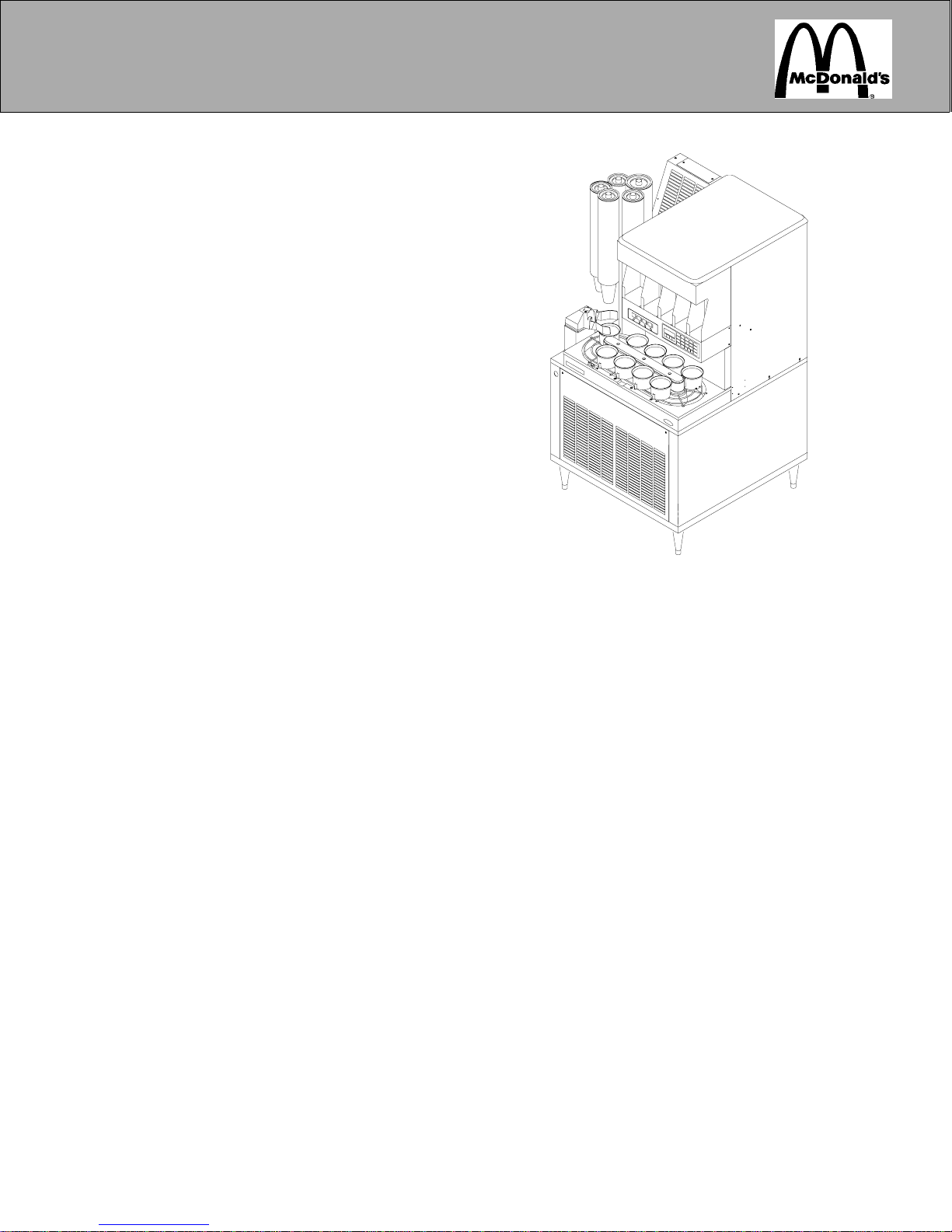
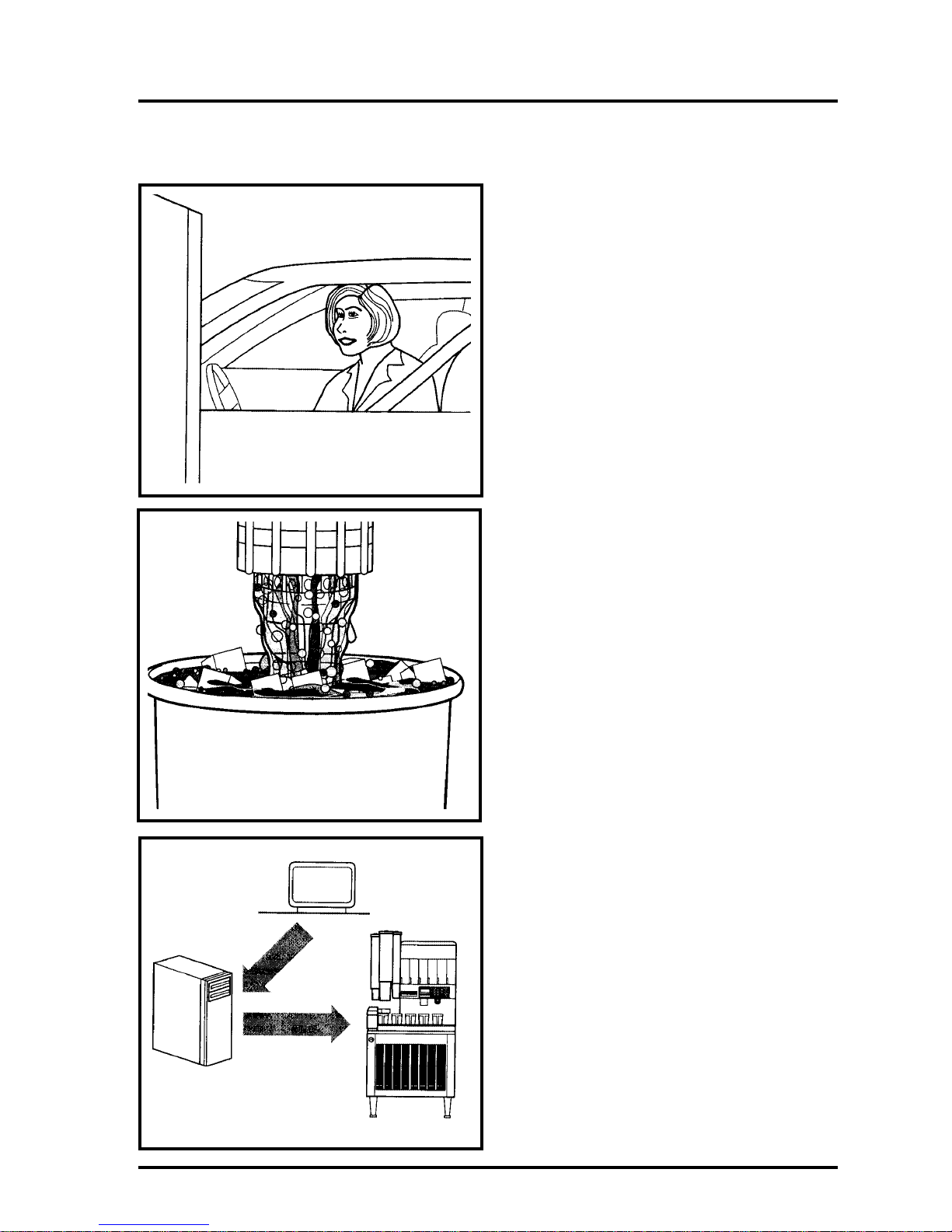
The Automated Beverage System (A.B.S.) is
an automated cold beverage dispenser for
drive-thru applications. When a cold beverage
is ordered from the P.O.S. register, the A.B.S.
will automatically drop the cup, fill it with ice,
and dispense the correct amount and type of
any syrup-based cold beverage. The finished
drink is then moved by the conveyor to the
pick-up station and the drink description is
displayed on the panel.
The Automated Beverage System has three
modes of operation:
• Automatic Mode
In automatic mode, the customer places an
order at the drive-thru and the A.B.S. automatically produces the order. If extra or no ice
drinks are ordered, they are entered from the
P.O.S. as a “grill order” and the A.B.S.automatically produces the drink as ordered.
• Semiautomatic Mode
While in automatic mode, the operator
resses the desired cup size button, the desired
flavor button and ENTER, then the drink is
dispensed. If extra ice or no ice is required,
the EXTRA ICE or NO ICE button is pressed
after the flavor button has been pressed before
ENTER, then the drink is dispensed.
• Manual Mode
A drink can also be dispensed in manual
mode. Remove the conveyor. Enter the manual mode by pressing the Manual/Auto button.
(Don’t pull cups from A.B.S. Turret damage
may occur to cup tubes.) Locate a sleeve of
cups and remove a cup. Hold the cup under
the ice chute, press EXTRA ICE and ice is
dispensed. Hold the cup under the nozzle,
press and hold the desired flavor button, and
the drink is dispensed. Reinstall the conveyor
and return the A.B.S. unit to normal operation.
SAFETY
T o avoid possible fatal electrical shock or serious injury to the Operator, it is highly recommended that a G.F.I. (ground fault circuit
interrupter) be installed in the electrical power
circuits to the unit.
Always disconnect power before cleaning or
servicing the unit. Do not use metal scrapers,
sharp objects or abrasives on the ice storage
hopper, top cover and the agitator disk, as
damage may result.
Always disconnect CO2 or air pressure to the
unit before cleaning or servicing the grabber
arm or ice chute. A disconnect switch for the
ice gate is located on the control box behind
the cup lid holder panel.
Insure that the unit is in manual mode before
removing or replacing the conveyor assembly
to avoid pinching fingers in the drain area.
The dispenser is very top heavy. To prevent
serious injury, exercise caution when moving
or setting the dispenser in place. The casters
that originally come with the unit should be
removed and replaced with the legs provided
in the installation kit to provide stability.
© 1999-2001 The Coca-Cola Company, Cornelius
and McDonald’s Corporation. All Rights Reserved.
4
Page 5
Automated Beverage System
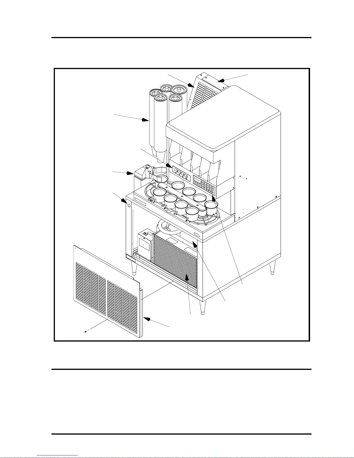
Illustrated Parts List
A.B.S. Unit Access
TURRET
FLAVOR DISPLAY
CUP GRABBER
ON/OFF SWITCH
1
2
Automated Beverage System —
Ref CCUSA MFG.
Number Number Number Description
1.................... ................560000260.....Ventilation Grill
PRINTED ON RECYCLED PAPER
2.................... ................560000245.....Access Hole Cover
10% Post-Consumer Content
3.................... ................560000291.....Air Filter
40% Pre-Consumer Cont ent
4.................... ................560000289.....Front Panel (Built before Serial No. 56A0019AB102)
...................... ................560002774.....Front Panel (Serial No. 56A0019AB102 and after)
© 1999-2001 The Coca-Cola Company, Cornelius
and McDonald’s Corporation. All Rights Reserved.
CONTROL PANEL
OPTIONAL PRECHILLER
3
4
Assembled Unit Diagram
5
Page 6
Automated Beverage System
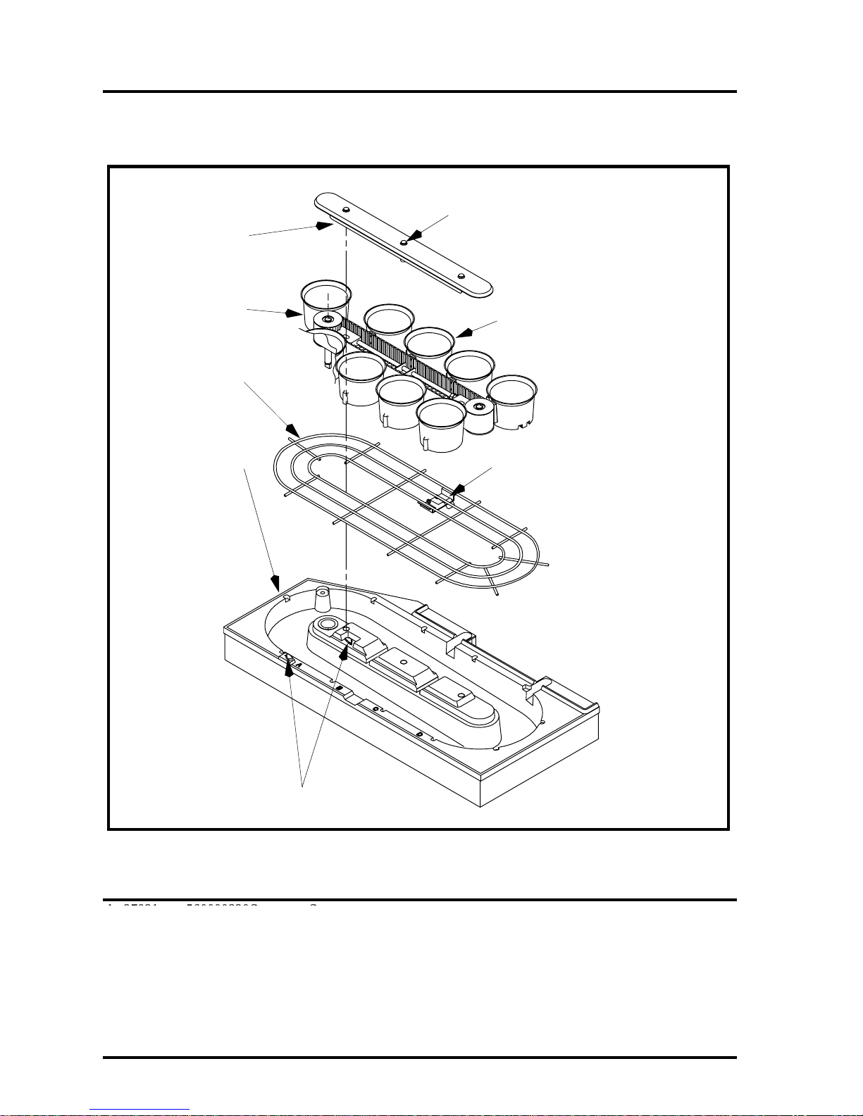
Illustrated Parts List
Conveyor Assembly
1
THUMB SCREWS
2
3
4
CUP HOLDER
CUP POSTIONING BRACKET
Automated Beverage System —
Ref CCUSA MFG.
Number Number Number Description
1 27921 ...... 560000320Conveyor Cover
1................ 27921...........560000320...... Conveyor Cover
2 ..............27922...................560000325 ..............Conveyor Assembly
2................ 27922...........569000295...... Conveyor Assembly
3 .............. .............................560000315 ..............Cup Rest
3................ .....................560000315...... Cup Rest
4 .............. .............................56 000 030 6..............Drip Tray Assembly
4................ .....................560000306...... Drip Tray Assembly
6
POSITION “A” SENSOR
Conveyor/Cup Rest Assembly Diagram
© 1999-2001 The Coca-Cola Company, Cornelius
and McDonald’s Corporation. All Rights Reserved.
Page 7
Automated Beverage System
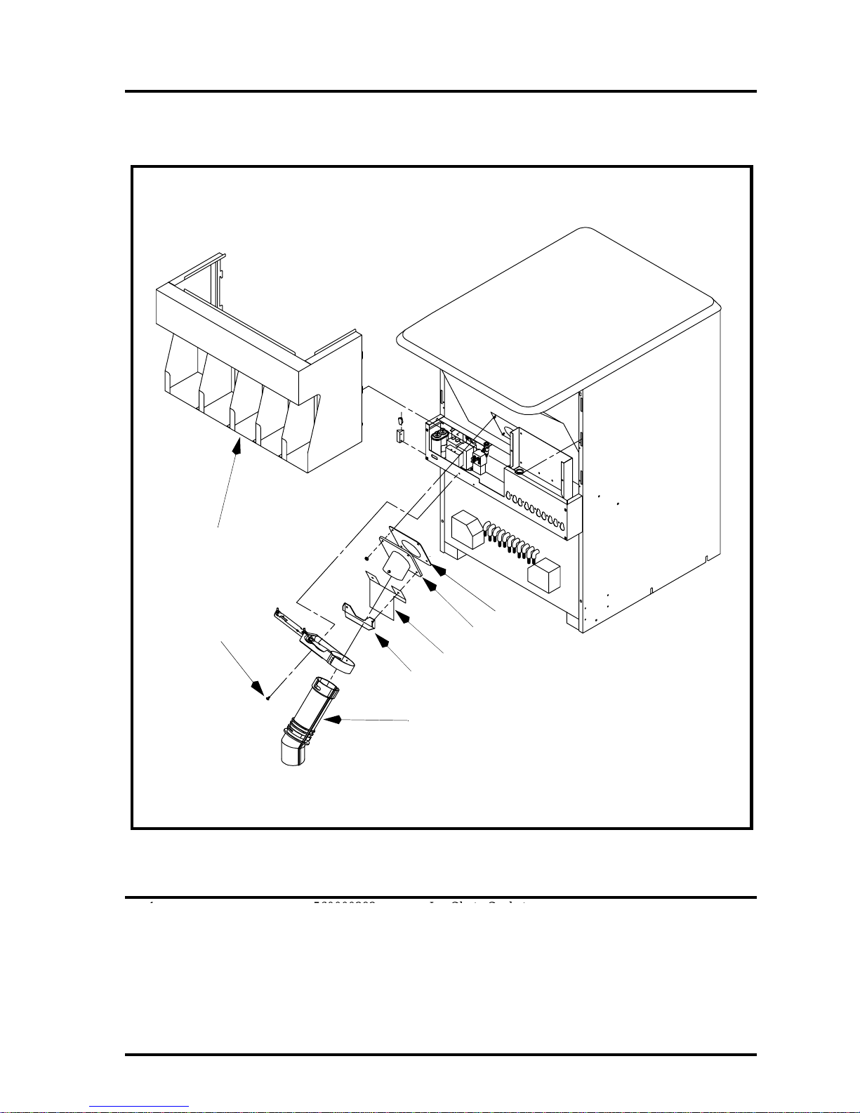
Illustrated Parts List
Ice Chute Assembly
7
1
5
4
3
Automated Beverage System —
Ref CCUSA MFG.
Number Number Number Description
1............... ............................560000392 ..............Ice Chute Gasket
1 ................ ...................560000392.....Ice Chute Gasket
2............... ............................560000344 ..............Ice Chute Mounting Plate
2 ................ ...................560000344.....Ice Chute Mounting Plate
3...............27926 ..................560000346 ..............Ice Chute
3 ................ 27926.........560000346.....Ice Chute
4............... ............................560002728 ..............Ice Chute Stiffener
4 ................ ...................560002728.....Ice Chute Stiffener
5............... ............................560000398 ..............Machine Screw, Phillips Truss Head, No. 8 x .5”
5 ................ ...................560000398.....Machine Screw, Phillips Truss Head, No. 8 x .5”
6............... ............................560001548 ..............Ice Chute Shield
6 ................ ...................560001548.....Ice Chute Shield
7............... ............................620014801 ..............Lid Holder Assembly
7 ................ ...................620014801.....Lid Holder Assembly
8...............28076 ..................560001589 ..............Ice Chute Cleaning Brush
8 ................ 28076.........560001589.....Ice Chute Cleaning Brush (Not Shown)
Ice Chute Assembly Components Diagram
2
6
© 1999-2001 The Coca-Cola Company, Cornelius
and McDonald’s Corporation. All Rights Reserved.
7
Page 8
Automated Beverage System
Illustrated Parts List
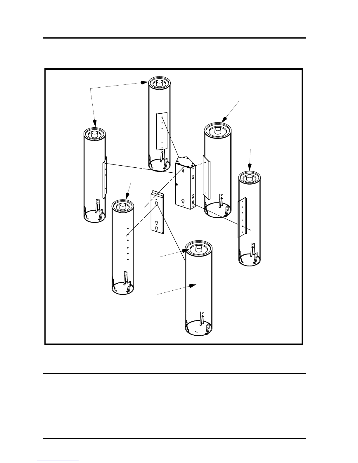
Cup Tube Assembly
2
2
1
2
Automated Beverage System —
Ref CCUSA MFG.
Number Number Number Description
1..............27916 ..........560000207 .......5” Cup Tube Cover (32 - 42 oz.)
2..............27915 ..........560000206 .......4” Cup Tube Cover (12 - 21 oz.)
3..............28377 ..........569000199 .......42 Oz. Cup Tube Kit
N/R .........28373 ..........569000172 .......12 Oz. Cup Tube Assembly Kit (Austrailian “Small” size)
N/R .........28374 ..........569000173 .......16 Oz. Cup Tube Assembly Kit (Austrailian “Medium” size, station 3)
N/R .........28375 ..........569000174 .......21 Oz. Cup Tube Assembly Kit (Austrailian “Large” size, station 1)
N/R ......... ....................569000175 .......32 Oz. Cup Tube Assembly Kit
N/R ......... ....................569000159 .......21 Oz. Cup Tube Assembly Kit (Austrailian “Large” size, station 2)
N/R ......... ....................569030035 .......Medium Cup Tube Assembly Kit Station 5, (Australian ABS only)
8
1
3
Cup Tube Components Diagram
© 1999-2001 The Coca-Cola Company, Cornelius
and McDonald’s Corporation. All Rights Reserved.
Page 9
Automated Beverage System
Illustrated Parts List
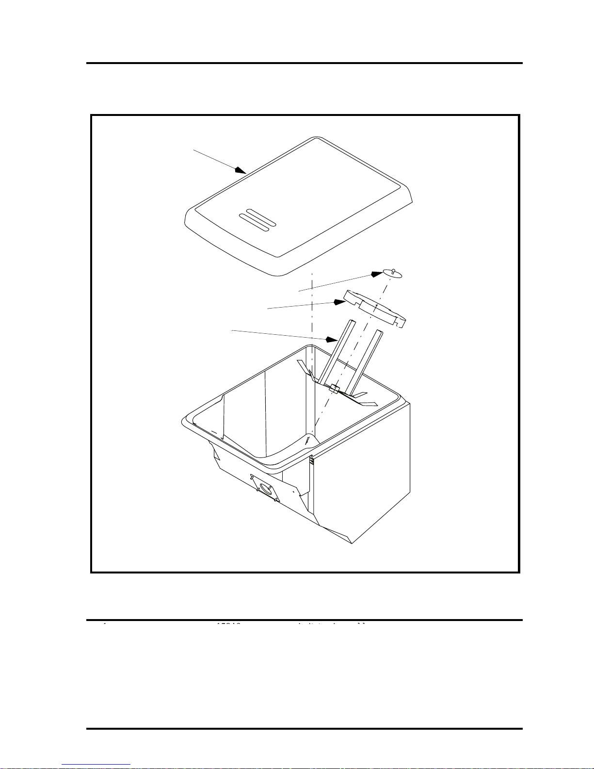
Agitator Assembly
2
4
3
1
Automated Beverage System —
Ref CCUSA MFG.
Number Number Number Description
1............... ............................15346 ......................Agitator Assembly
1 ..............15346................................Agitator Assembly
2............... ............................52887 ......................Lid
2 ..............52887................................Lid
3............... ............................53227 ......................Disk
3 ..............53227................................Disk
4............... ............................15087 ......................Agitator Retainer
4 ..............15087................................Agitator Retainer
© 1999-2001 The Coca-Cola Company, Cornelius
and McDonald’s Corporation. All Rights Reserved.
Ice Bin Components Diagram
9
Page 10
Automated Beverage System
Illustrated Parts List
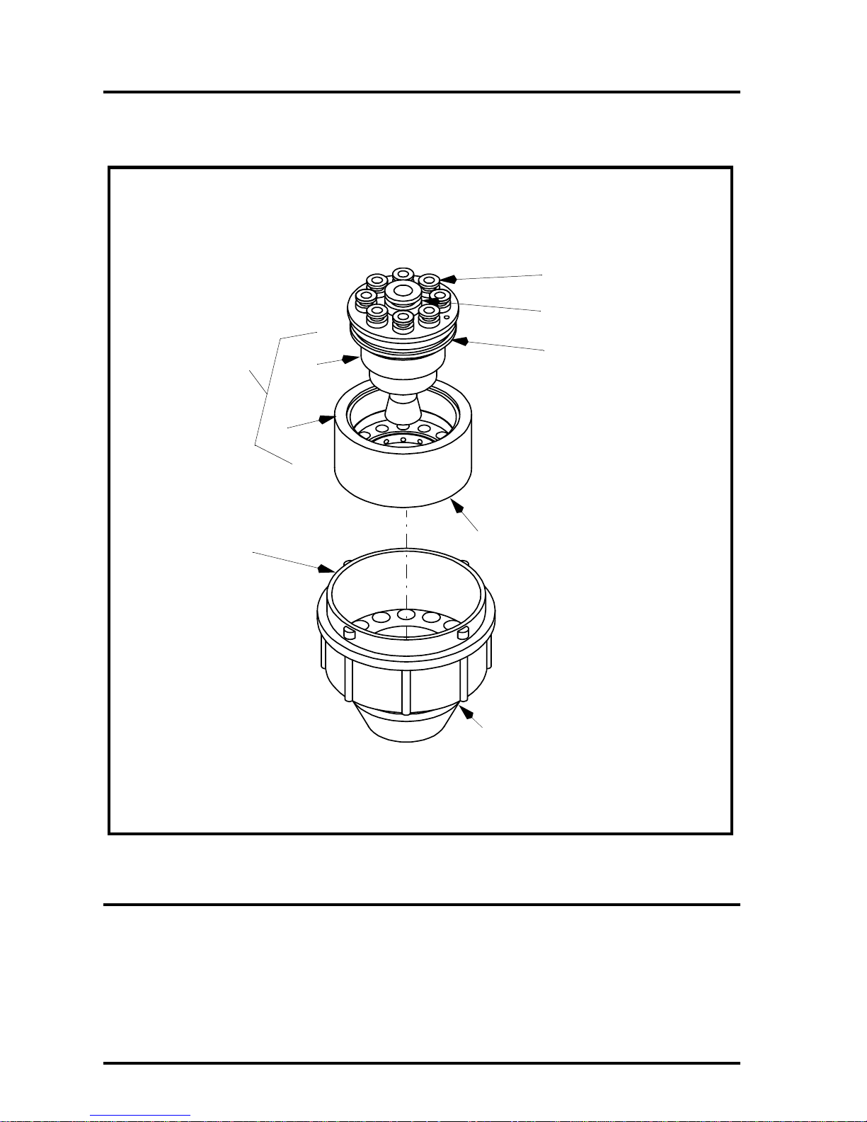
Nozzle Assembly
3
4
2
1
1
2A
2B
DIFFUSER BODY
DIFFUSER RING
5
Automated Beverage System —
Ref CCUSA MFG.
Number Number Number Description
1................27940 560001545..........Nozzle
2................27939 560001544..........Diffuser
3................ 110677000..........O-Ring
4................ 180025000..........O-Ring
5................ 560110010..........O-Ring
6................ 325216000..........Nozzle Brush (Not Shown)
10
Nozzle Assembly Components Diagram
© 1999-2001 The Coca-Cola Company, Cornelius
and McDonald’s Corporation. All Rights Reserved.
Page 11
Operational Modes
The A.B.S. has three modes of operation:
• Automatic (Normal Operation)
• Semiautomatic (while in Au to)
•Manual
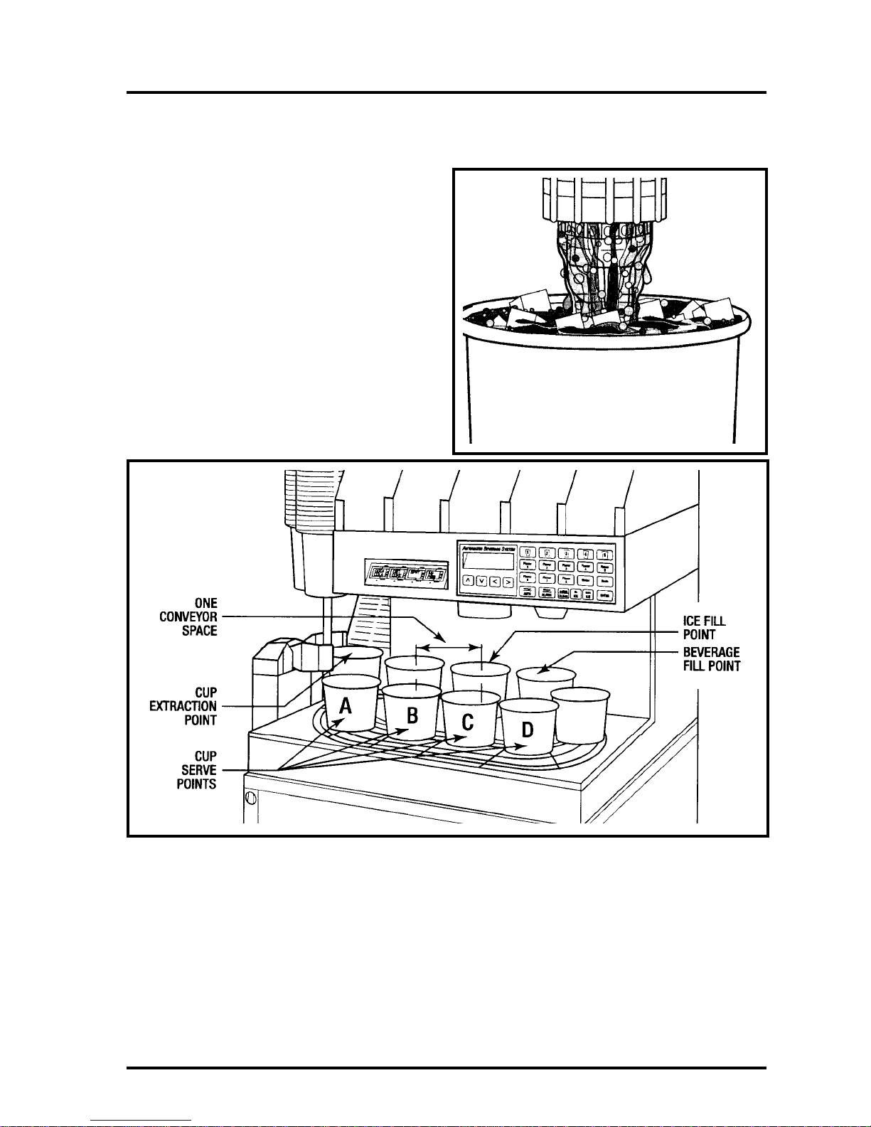
Automated Beverage System
Fully Automatic Operation
Location Diagram
© 1999 The Coca-Cola Company, Cornelius and
McDonald’s Corporation. All Rights Reserved.
11
Page 12
Automated Beverage System
Automatic Operation
Order Entered On P.O.S.
With the unit in a utomatic mode, the customer
places an order at the Drive-Thru.
Special Ice Drinks
Extra and no ice drinks are entered from the
P.O.S. as a “grill order.” The A.B.S. will automatically produce the drink to the special
order.
P.O.S. Signal To Manager’s Computer
The order is transmitted from the P.O.S. to the
store computer and from there to the A.B.S.
unit.
12
© 1999 The Coca-Cola Company, Cornelius and
McDonald’s Corporation. All Rights Reserved.
Page 13
Automated Beverage System
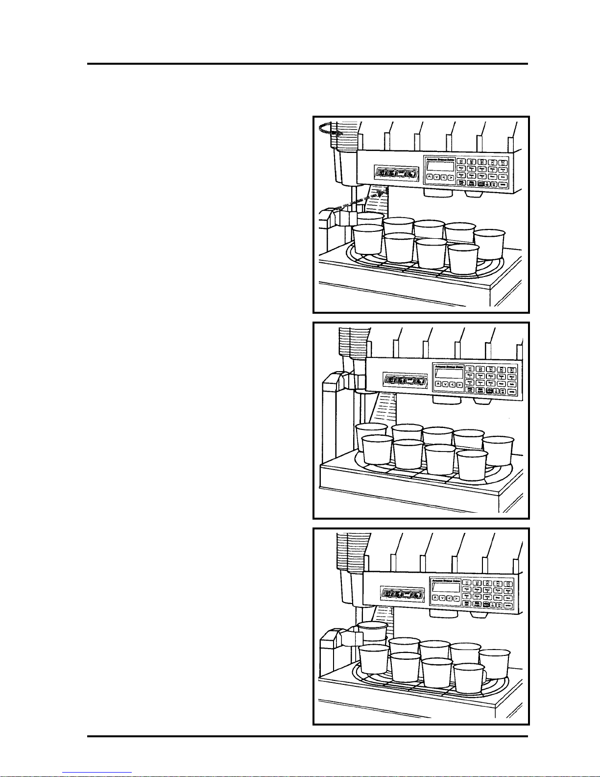
Cup Turret Rotates
After the photo sensor checks for cup too high
condition, the cup turret rotates to move the
proper size cup to the extract position.
Automatic Operation
Cup Grabber Rises & Closes
The cup grabber is lifted by a pneumatic cylinder up to the cup. The travel is sensed by the
full travel sensor. If full height is reached, a
pneumatic cylinder closes the grabber arms
against the cup. A sensor detects if cups are
available.
Grabber Lowers & Opens
The cup grabber lowers, pulling the cup from
the cup tube and then the arms open dropping
the cup into the conveyor.
If the grabber should slide off a cup, it would
be detected by the cup sensor.
© 1999 The Coca-Cola Company, Cornelius and
McDonald’s Corporation. All Rights Reserved.
13
Page 14
Automated Beverage System
Automatic Operation
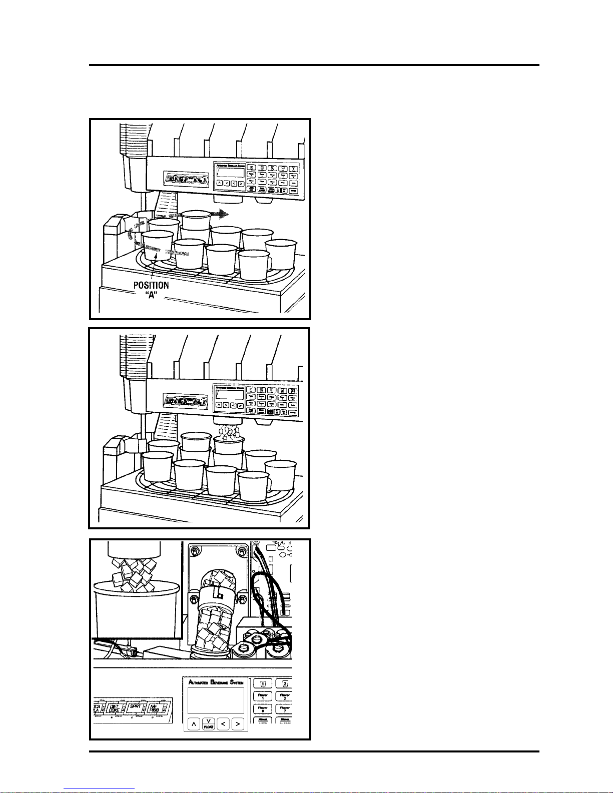
Conveyor Operates
Sensors check for cup too high and a cup in
position “A.” If these are clear, the conveyor
rotates clockwise to move the cup to the ice
chute.
This is based on only one drink being ordered.
If a second drink had been ordered, the conveyor would have moved only one position
and the second cup would have been extracted
and dropped into the conveyor. The two cups
would then be moved clockwise until the first
cup reaches the ice fill port.
Ice Portion Is Dispensed
The ice gate is opened by a pneumatic cylinder for the time needed to dispense the
selected ice portion. Correct operation is
insured by the ice gate full travel sensor.
14
The agitator continues to operate for the set
refill time to refill the ice chute.
© 1999 The Coca-Cola Company, Cornelius and
McDonald’s Corporation. All Rights Reserved.
Page 15
Automated Beverage System
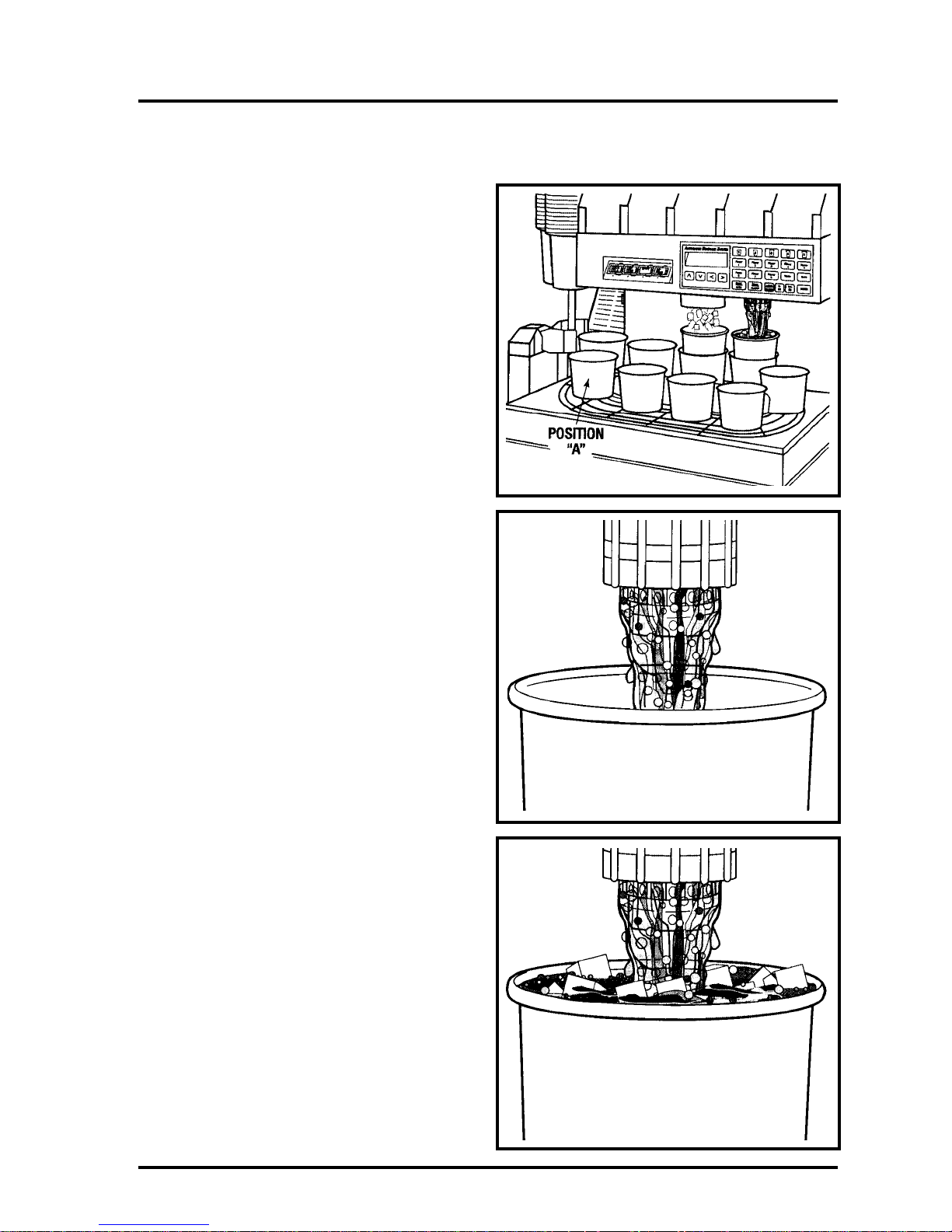
Cup To Dispensing Nozzle
Sensors check for cup too high and a cup in
position A. If these sensors are clear, the conveyor moves the cup to the beverage fill poi nt.
The valve opens to dispense the desired syrup
and water in the desired portions into the cup.
Automatic Operation
Beverage Dispensed
The computer sends the drink portion of the
order to the A.B.S. where the information is
interpreted and the drink is dispensed.
If the drink requires a top-off, the initial portion will be dispensed. After a delay, the balance of the drink will be dispensed.
© 1999 The Coca-Cola Company, Cornelius and
McDonald’s Corporation. All Rights Reserved.
15
Page 16
Automated Beverage System
Automatic Operation
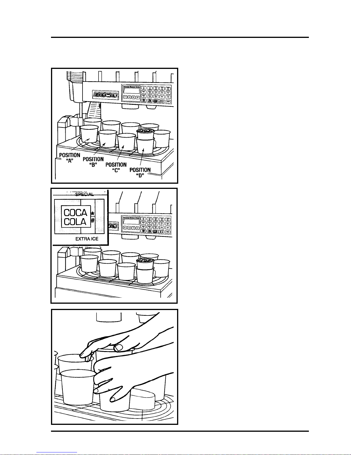
Cup Is Moved To Cup Serve Point
Sensors check for cup too high and a cup in
position “A.” If these sensors are clear, the
conveyor moves the cup to cup serve position
“D.”
The display will indicate the flavor of the beverage at cup serve position “D.”
Crew Member Serv es Drink
A crew member caps the drink while still on
the conveyor and serves it with the remainder
of the order.
16
© 1999 The Coca-Cola Company, Cornelius and
McDonald’s Corporation. All Rights Reserved.
Page 17
Automated Beverage System
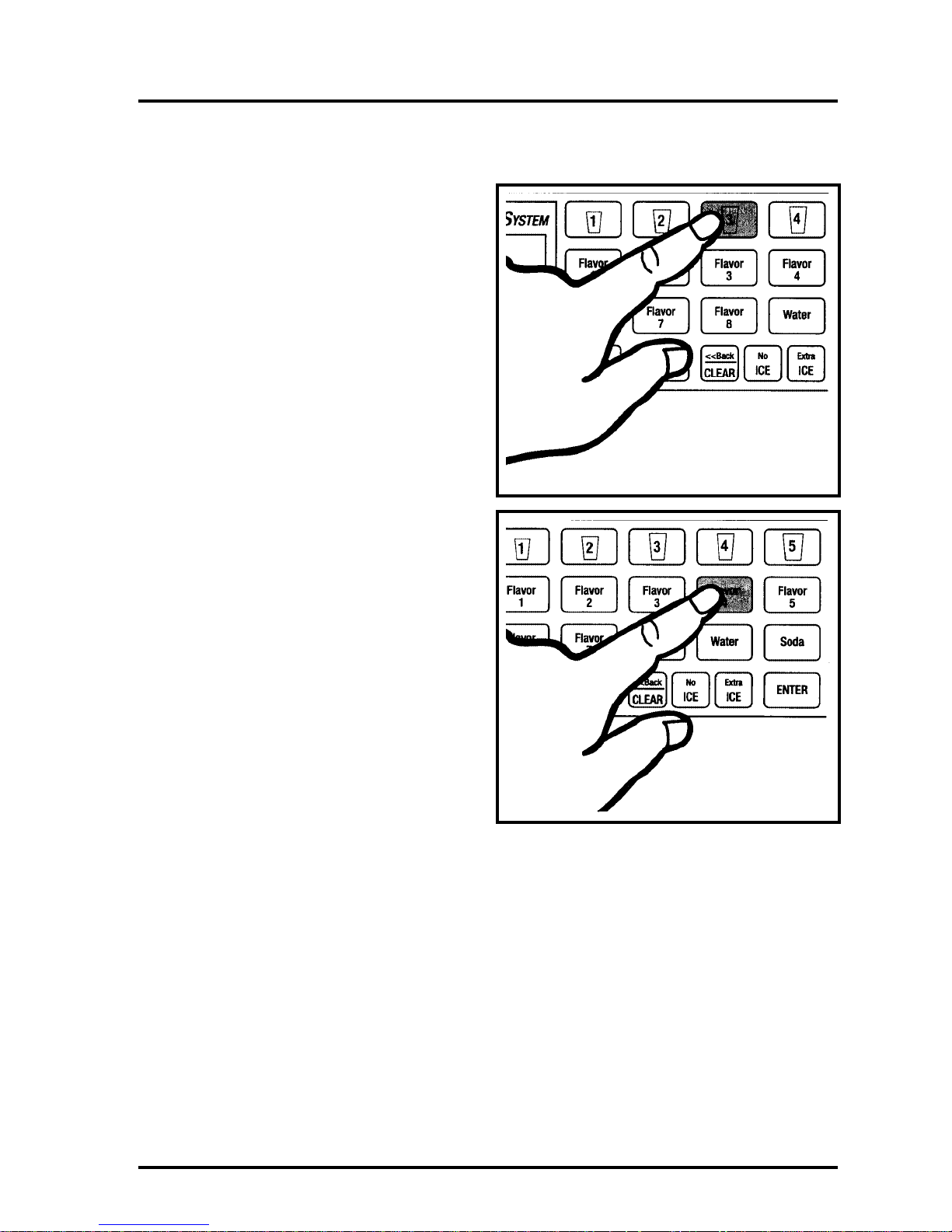
Semiautomatic Operation (Unit in Automatic)
Press Cup Size
While in automatic mode, to dispense a drink
in the semi-automatically, press the desired
cup size button.
Press Flavor
Press the desired flavor button.
© 1999 The Coca-Cola Company, Cornelius and
McDonald’s Corporation. All Rights Reserved.
17
Page 18

Automated Beverage System
Semiautomatic Operation (Unit in Automatic)
Press Special Ice Requirement If
Requested
If extra ice is desired, press the EXTRA ICE
button. If no ice is required, press the NO ICE
button.
If normal ice is desired, no button is pressed.
When Correct, Press Enter
Sequence of pressing the cup size, flavor, and
special ice buttons is not important. At any
time, pressing any button will change the
selection of the drink to be dispensed. When
the correct order is displayed, press ENTER
and the drink will be dispensed.
Any drink entered in this manner will display
an illuminated asterisk in the SPECIAL section of the Drink Position Display identifying
the semiautomatic drink selected at the A.B .S.
panel.
18
© 1999 The Coca-Cola Company, Cornelius and
McDonald’s Corporation. All Rights Reserved.
Page 19

Automated Beverage System
Enter Manual Mode
Enter the manual mode by pressing the Manual/AUTO button.
Manual Operation
Remove The Conveyor
To dispense a drink in the manual mode,
remove the conveyor. This is done by removing the thumb screws holding it in place and
lifting the conveyor up.
Never Remove Cups From Cup Turret
Assembly
Manually pulling cups from the cup tubes can
permanently damage the retainers.
Stock cup sleeves near the unit when in manual mode.
© 1999 The Coca-Cola Company, Cornelius and
McDonald’s Corporation. All Rights Reserved.
19
Page 20

Automated Beverage System
Manual Operation
Dispense Ice
Hold the cup under the ic e chute. Dispe nse ice
by pressing the EXTRA ICE button.
Ice Not Dispensed
If there is an issue with CO2, ice may not dispense. In this case, locate a supply of ice near
the unit for manually filling the cups.
Dispense Beverage
Hold the cup under the nozzle. Press and hold
the desired flavor button to dispense the beverage.
20
© 1999 The Coca-Cola Company, Cornelius and
McDonald’s Corporation. All Rights Reserved.
Page 21

Automated Beverage System
Return The A.B.S. To Normal
Operation
Reinstall the cup conveyor by aligning the
drive pin on the left side of the conveyor
assembly so that the conveyor seats properly.
The conveyor drive pin must engage the drive
socket on the gear box. When installing the
conveyor, it may be necessary to move the
conveyor manually to allow the drive pin to
insert into the drive socket.
Tighten the thumb screws on the cover.
Manual Operation
Clear The P.O.S. Order Buffer
If orders are on the screen, the P.O.S. buffer
must be cleared. To clear the P.O.S. buffer , the
A.B.S. unit must be in the MANUAL mode.
Press the UP arrow to highlight the “XXX
ORDERS”.
© 1999 The Coca-Cola Company, Cornelius and
McDonald’s Corporation. All Rights Reserved.
21
Page 22

Automated Beverage System
Manual Operation
A confirmation question will appear. Press
ENTER to clear the entire order buffer or
CLEAR to cancel action.
Return To Automatic Mode
Press the Manual/AUTO button to return to
Automatic mode.
22
© 1999 The Coca-Cola Company, Cornelius and
McDonald’s Corporation. All Rights Reserved.
Page 23

Automated Beverage System
Introduction to the A.B.S. Unit
Major Subsystems
Components of the A.B.S.
• Turret
• Cup Lid Rack
• Ice Dispenser
• Control Panel
• Cup Extractor
• Conveyor
• Beverage Dispenser
• Pre-Chiller (Optional)
© 1999 The Coca-Cola Company, Cornelius and
McDonald’s Corporation. All Rights Reserved.
23
Page 24

Automated Beverage System
A.B.S. Unit Major Subsystems
Control Touch Panel
ARROW (CURSOR) DOWN/FLOAT OPTION-Used to move the selection to the down
ARROW (CURSOR) DOWN/FLOAT OPTION-Used to move the selection to the down when in manual mode, used to
when in manual mode, used to add float to ordered drink in Automatic mode.
add float to ordered drink in Automatic mode.
24
© 1999 The Coca-Cola Company, Cornelius and
McDonald’s Corporation. All Rights Reserved.
Page 25

Automated Beverage System
Touch Panel Description
Each button on the Touch Panel is described
in detail in the Touch Panel Diagram on page
24.
Whenever any button is pressed, there is an
audible Beep. If the button is incorrect and
cannot function, there will be a triple Beep
indicating an error.
Display, Touch Panel
A.B.S. Unit Major Subsystems –
Control Touch Panel
The display that is visible through the window
in the Touch Panel is the message center for
the A.B.S. The display examples shown is
only one of the many messages that may be
displayed.
This display shows the status, guides you
through programming, tells you what errors
have occurred, the number of cycles on a
component and other messages.
© 1999 The Coca-Cola Company, Cornelius and
McDonald’s Corporation. All Rights Reserved.
25
Page 26

Automated Beverage System
A.B.S. Unit Major Subsystems
Control Panel, Drink Position
Drink Position Display
The Drink Position Display corresponds to
the four drink pickup positions on the conveyor. As a drink moves to position “D” on
the conveyor, the details of the drink are displayed.
26
© 1999 The Coca-Cola Company, Cornelius and
McDonald’s Corporation. All Rights Reserved.
Page 27

Automated Beverage System
A drink that is dispensed from the touch panel
and not from the P.O.S. will be indicated as a
SPECIAL. This will be indicated by the *
being illuminated in the display.
A.B.S. Unit Major Subsystems –
Control Panel, Drink Position
If the drink has the special ice requirements
If the drink has the special ice requirements
EXTRA ICE, the # will be illuminated in the
EXTRA ICE, the # will be illuminated in the
display.
display.
If the drink is a FLOAT drink, F will be illuminated in the display.
ROOT
© 1999 The Coca-Cola Company, Cornelius and
McDonald’s Corporation. All Rights Reserved.
BEER
FL
F
27
Page 28

Automated Beverage System
A.B.S. Unit Major Subsystems
Operation —
Turret, Cup Extractor, & Conveyor
Cup T urret Components – Location Diagram
Cup Turret Components – Location Diagram
Cup Conveyor Components – Location Diagram
Cup Conveyor Components –Location Diagram
28
© 1999 The Coca-Cola Company, Cornelius and
McDonald’s Corporation. All Rights Reserved.
Page 29

Automated Beverage System
A.B.S. unit Major Subsystems Operati on —
Cup Tubes Configuration
The cup tube configuration is 1 – Small; 1 –
Child; 1 – Large; 1 – Medium; 1- XL.
Turret
The cup tube configuration for Australia is 1 –
Small; 2 – Large; 2 – Medium.
The hole mounting pattern is such that the cup
tubes will only mount in one location.
Rotating The Cup Turret
While in the manual mode – press the Cup
Size button corresponding to the cup tube you
wish to install. The turret will rotate until the
correct turret face is forward, allowing easy
mounting of the cup tube. In the standard configuration, the 5th cup size is not being used.
If there are two medium cup tubes, when button #3 is pressed once the first medium turret
cup face is forward, the second time it is
pressed the second medium turret face will
rotate forward.
MD
Other Cup Configuration
The unit can be configured with four or five
cup sizes. If only four cup sizes are needed,
usually two medium cup tubes are used.
The second medium cup tube can be omitted
and an extra large cup substituted. The extra
large cup tube mounting location can be identified by pressing cup size button #5.
© 1999 The Coca-Cola Company, Cornelius and
McDonald’s Corporation. All Rights Reserved.
29
Page 30

Automated Beverage System
A.B.S. unit Major Subsystems Operation —
Cup Extractor
Cup Grabber Assembly
The cup grabber consists of two cup grabber
arms actuated by a pneumatic cylinder, an elevating mechanism operated by a pneumatic
cylinder, two guide rods, a Travel sensor and
a Cup Empty sensor. The Cup Too High Sensor is located on the grabber assembly.
Cup Grabber Cycle
When the correct cup is aligned at the cup
grabber, a pneumatic cylinder lifts the cup
grabber to the cup. A sensor detects the full
travel of the grabber during the lift motion. A
signal is sent that the grabber is in position
and then a pneumatic cylinder closes the grabber arms. If the arms close fully indicating
“No Cup,” the control system will attempt to
pull a cup from a second tube of same size cup
if present. If no cup is available a “SOLD
OUT” message will be displayed. If a cup is
available the cup grabber will be lowered and
the cup pulled from the cup tube.
If the grabber arms close on a cup but during
the lowering of the cup it falls incorrectly, a
“CUP JAM” message will be displayed.
When the grabber successfully pulls a cup
from the cup tube and is completely lowered,
the grabber arms will open, dropping the cup
into the conveyor. The conveyor will then
advance and continue to make drinks.
30
© 1999 The Coca-Cola Company, Cornelius and
McDonald’s Corporation. All Rights Reserved.
Page 31

Automated Beverage System
A.B.S. unit Major Subsystems Operati on —
Conveyor
The conveyor contains nine equally spaced
cup holders. Each cup holder contains a
ceramic magnet. A sensor located in the drip
pan at the cup grabber detects the cup holders
and thereby controls the movement of the
conveyor and the position of the cup holders.
Note: The conveyor will not operate if there is
a cup or any obstruction in the cup holder at
Cup Serve
Point “A.”
Conveyor
Cup Rest
The cup rest must be installed with the oval
rails up and with the “Cup Positioning
Bracket” must be at the rear of the drip tray.
Drive Seal
Check to see drive seal is installed properly.
© 1999 The Coca-Cola Company, Cornelius and
McDonald’s Corporation. All Rights Reserved.
31
Page 32

Automated Beverage System
A.B.S. unit Major Subsystems Operation —
Conveyor
Cup Positioning Bracket
The cup positioning bracket, located on the
cup rest, contains a spring that is positioned so
it touches the cup in the cup holder as the cup
moves past the spring. This moves the cup to
the rear (based on the direction of movement)
of the cup holder. This insures that all cups
will be in the same position for dispensing
regardless of its size.
Cup In Position “A”
Part of the conveyor assembly is the cup in
position “A” sensor. This senses if a cup is in
the last conveyor position to prevent full cups
from traveling into the grabber mechanism.
Reinstall Conveyor
Align the drive pin on the left side of the conveyor assembly so that the conveyor seats
properly . The conveyor drive pin must engage
the drive socket on the gear box. When installing the conveyor, it m ay be necessary to move
the conveyor manually to allow the drive pin
to insert into the drive socket.
Tighten the thumb screws on the cover.
32
© 1999 The Coca-Cola Company, Cornelius and
McDonald’s Corporation. All Rights Reserved.
Page 33

Automated Beverage System
A.B.S. unit Major Subsystems Operation —
Ice Gate Description
The ice gate is a pneumatically operated
“gate” that is controlled by the Beverage
Interface Board. The time the gate is open is
very precise and determines the portion of ice
dispensed. The gate opens and closes under
pneumatic pressure. The gas is controlled by
solenoids.
Ice Dispenser
Ice Dispensing Cycle
The ice gate opens; the agitator turns to refill
the ice chute and to maintain ice on the coldplate; the ice gate closes; the agitator continues to fill the ice chute fr the set period of
time.
Low Ice – Refill Soon
The LOW ICE – REFILL SOON condition is
sensed by the A.B.S. through a temperature
sensor located in the ice bin.
The LOW ICE – REFILL SOON alarm
sounds when the bin has about 40 drinks left
in its capacity . It wil l resound with every tenth
drink made, until refilled.
© 1999 The Coca-Cola Company, Cornelius and
McDonald’s Corporation. All Rights Reserved.
33
Page 34

Automated Beverage System
A.B.S. unit Major Subsystems Operation —
Ice Dispenser
Auto-Agitate
Ice from the bin is used for the coldplate.
If the A.B.S. unit is idle for a period (pro-
grammed during setup), the agitator will agitate for a preset period to maintain ice on the
coldplate.
The ice bin has a sensor that detects a low ice
condition and displays a warning.
Ice Chute
The ice chute directs the ice into the cup. It
can be removed for cleaning or replacement.
Access to the ice chute is obtained by removing the cup lid rack.
34
© 1999 The Coca-Cola Company, Cornelius and
McDonald’s Corporation. All Rights Reserved.
Page 35

Automated Beverage System
A.B.S. Unit Major Subsystems Operation —
Ice Chute Removal & Replac eme nt
1.With the unit in manual mode, remove the
cup lid rack.
Ice Dispenser
2.WARNING: Shut off the manual ice gate
switch.
3.Slide the gate out of the chute.
© 1999 The Coca-Cola Company, Cornelius and
McDonald’s Corporation. All Rights Reserved.
35
Page 36

Automated Beverage System
A.B.S. Unit Major Subsystems Operation —
Ice Dispenser
4.Pull the ice chute release mechanism out
and turn the chute clockwise 1”.
5. Holding the ice chute release mechanism,
rotate the ice chute clockwise and pull down.
Drop the ice chute down through the ice gate
frame and replace it. To reinstall ice chute,
follow procedures in reverse order.
6. Return the A.B.S. unit to normal operation.
36
© 1999 The Coca-Cola Company, Cornelius and
McDonald’s Corporation. All Rights Reserved.
Page 37

Automated Beverage System
A.B.S. Unit Major Subsystems Operation —
Valve Description
The dispensing valve is located behind the
touch panel and is made up of five blocks,
each containing two solenoids, two flow controls, and two shutoffs. The blocks are permanently manifolded together to supply a single
outlet nozzle. (The top view is depicted.)
Beverage Dispenser
Beverage Dispensing
The valve opens to dispense the desired syrup
and water in the desired portions into the cup.
If foaming is an issue, the service agent can
program a top-off. The initial portion will be
dispensed. After a delay, the balance of the
drink will be dispensed.
© 1999 The Coca-Cola Company, Cornelius and
McDonald’s Corporation. All Rights Reserved.
37
Page 38

Automated Beverage System
A.B.S. Unit Major Subsystems Operation —
Pre-Chiller
Optional Pre-Chiller
An optional pre-chiller must be installed if
carbon-ated water and plain water are not
chilled in a backroom package.
38
© 1999 The Coca-Cola Company, Cornelius and
McDonald’s Corporation. All Rights Reserved.
Page 39

Automated Beverage System
Fill Ice Bin
Remove the ice bin lid and fill with ice cubes
to the top of the bin. Do not overfill. The bin
cover must be able to rest securely on the top
of the bin.
Daliy Start-Up Procedures —
Fill Ice Bin
© 1999 The Coca-Cola Company, Cornelius and
McDonald’s Corporation. All Rights Reserved.
39
Page 40

Automated Beverage System
Daliy Start-Up Procedures —
Filling Cup Tubes
Rotating The Cup Turret
Place the unit in the manual mode – press the
Cup Size button corresponding to the cup tube
you wish to fill. The turret will rotate until the
correct turret face is forward, allowing easy
filling of the cup tube.
Filling Cup Tubes
Remove top cup tube cover and hold under
the cup tube to catch cups and prevent them
from falling through.
Return top cup tube cover.
Do not over fill the cup tubes. Damage may
result to the cup tubes or may result in cup
jams.
When all tubes have been filled, return to
automatic mode by pressing the Manual/Auto
button.
40
© 1999 The Coca-Cola Company, Cornelius and
McDonald’s Corporation. All Rights Reserved.
Page 41

Automated Beverage System
Daily Cleaning/ Sani ti zing Tasks
At close, the following tasks should be performed:
• Put in manual mode (do not shut off main
power).
• Remove and clean the conveyor, and cup rest.
• Clean drip tray and exterior surfaces.
• Pou r warm (NOT HOT) water do wn the drip
tray drain.
• Reinstall cup rest and conveyor.
• Remove and clean the valve nozzle and diffuser.
• Wipe down and clean the A.B.S. unit with sanitizing solution.
Closing/Sanitation Procedures
Remove Conveyor & Cup Rest
Remove the conveyor by removing the 3
thumb screws holding it in place. Remove the
cup rest by lifting it up and removing it. W ash
the conveyor, conveyor cover, and the cup
rest in warm soapy water then rinse with clean
potable water.
© 1999 The Coca-Cola Company, Cornelius and
McDonald’s Corporation. All Rights Reserved.
41
Page 42

Automated Beverage System
Closing/Sanitation Procedures
Clean Drip Tray & Exterior Surfaces
Clean drip tray and all exterior surfaces with
warm soapy solution and rinse with clean
potable water.
Pour warm (NOT HOT) water down the drip
tray drain to flush drain line.
Inspect drive seal after cleaning to check for
proper installation.
Reinstall Cup Rest
The cup rest must be installed with the oval
rails up and the “Cup Positioning Bracket”
must be at the rear of the drip tray.
The cup positioning bracket, located on the
cup rest, contains a spring that is positioned so
it touches the cup in the cup holder as the cup
moves past the spring. This moves the cup to
the rear (based on the direction of movement)
of the cup holder. This insures that all cups
will be in the same position regardless of its
size.
Reinstall Conveyor
Align the drive pin on the left side of the conveyor assembly so that the conveyor seats
properly . The conveyor drive pin must engage
the drive socket on the gear box. When installing the conveyor, it m ay be necessary to move
the conveyor manually to allow the drive pin
to insert into the drive socket.
42
Tighten the thumb screws on the cover.
© 1999 The Coca-Cola Company, Cornelius and
McDonald’s Corporation. All Rights Reserved.
Page 43

Automated Beverage System
Clean Nozzle & Diffuser
• Remove the nozzle by twisting clockwise. Then
pull the diffuser straight down. Separate the diffuser. Clean the beverage nozzle and diffuser
using nozzle brush and rinse with carbonated
water.
• Reinstall diffuser nozzle
Closing/Sanitation Procedures
Wipe Down A.B.S. Unit
At the end of closing shift, the crew should
wipe down the exterior of the unit with a sanitizing solution.
© 1999 The Coca-Cola Company, Cornelius and
McDonald’s Corporation. All Rights Reserved.
43
Page 44

Automated Beverage System
Monthly Cleaning/Sa nitation Procedures
Cleaning Conveyor Thru-Beam (Last Position) Sensor
The thru-beam (Position “A”) sensor requires cleaning. If not clean, the sensor may work
intermittently.
With the conveyor off, wet a clean napkin with carb water and carefully wipe the lens of the
thru-beam sensor emitter and the receiver.
(Note: Don’t use cleaning towel on sensor, it may leave film on sensor lens.)
Monthly Cleaning/Sanitation of Ice Bin
WARNING: DO NOT USE SHARP OBJECTS, METAL DEVICES OR ABRASIVES ON THE ICE
HOPPER, TOP COVER, ICE CHUTE OR AGITATOR DISC AS IRREPARABLE DAMAGE MAY
RESULT. DO NOT USE SOLVENT OR OTHER CLEANING AGENTS AS THEY MAY ATTACK
THE PLASTIC MATERIAL.
Soapy Solution:
Sanitizing Solution:
water. Preparing the sanitizing solution at this ratio will create a solution of 200 PPM chlorine.
1. Turn ABS unit power switch OFF. The switch is located on the lower left-hand side of the ABS unit
front panel.
2. Remove top cover and set aside.
3. Remove all ice from the hopper and discard. If necessary, pour clean, potable water slowly into the
hopper to assist in melting the ice.
4. After all the ice is removed inspect the cold plate areas and drains as follows:
A. Remove the splash panel and the plastic cold plate access cover.
Use a mixture of mild detergent and warm (100oF) potable water.
Use 1/2 ounce of non-s cented household bleach in one gallon of potable
© 1999 The Coca-Cola Company, Cornelius and
McDonald’s Corporation. All Rights Reserved.
44
Page 45

Automated Beverage System
Monthly Cleaning/Sanitation Procedures
B. Locate and remove any debris from the drain trough and cold plate. Make sure the drain holes
are not clogged.
C. Reinstall the cold plate access cover and splash panel.
5. Remove the agitator retainer and the ice agitator assembly.
6. Using a long handled nylon bristle brush, clean the interior of the hopper, top cover, agitator,
agitator cover and cold plate with warm, soapy solution. The cold plate is to be cleaned by
reaching through the ice openi ng into the hop per botto m with the long handle brush. Be certai n to
clean the entire surface area of the cold plate including all the corners. Thoroughly rinse the
hopper, top cover, agitator, agitat or cover and the cold plate with clean potable water.Automated
Beverage System
7. Using a long handle nylo n bristle brush, clean the interior of the ice chute with the warm, soapy
solution. Access to the to the ice chute can be gained via the inter ior of the hopper and the ice
chute outlet on the front of the ABS unit. Thoroughly rinse the ice chute with clean, potable water.
8. Reinstall the agitator assembly.
9. Using a mechanical spray bottle filled with sanitizi ng solution, spray the entire interi or of the ice
bin, ice chute and ice agitator assembly. Allow to air dry.
10. Turn the ABS unit power switch ON.
11. Return the ABS unit to AUTO mode.
45
© 1999 The Coca-Cola Company, Cornelius and
McDonald’s Corporation. All Rights Reserved.
Page 46

Automated Beverage System
Quarterly Cleaning/Sanitation Procedures
UARTERLY SANITATION OF POST-MIX SYRUP SYSTEM
Q
IMPORTANT: Only qualified Service Personnel should perform the sanitizing procedure on
the post-mix syrup systems.
The post-mix syrup systems should be sanitized every 90 days using a non-scented household
liquid bleach containing a 5.25% sodium hypochlorite concentration. Proceed as follows to
sanitize the post-mix syrup systems.
1. Disconnect syrup supplies from the syrup systems.
2. Rinse the quick disconnects (syrup tank systems) or bag-in-box connectors (syrup bag-in-box
systems) in warm, potable water.
STEP 1: WASH THE SYRUP SYSTEMS
WARNING: To avoid possible personal injury or property damage, do not attempt
to remove the syrup tank cover until CO
pressure has been released from the
2
3. Using a clean syrup tank (syrup tank system) or a five gallon container (bag-in-box system),
o
prepare a full tank or c ontainer of liquid dishwash er detergent by using 70
o
C) potable water and 5 oz.(15 ml) of liquid dish washer detergent to one gallon of potable
(38
water.Stir detergent solution to thoroughly mix the solution.
4. Syrup Tank Systems
A. Observe and n ote CO
regulator to 60 to 80 PS I. Pr essur ize t he syr up tank , that conta ins the deterg ent s olutio n
CO
2
to 60 to 80 PSI.
B. Connect the pressurized (60 to 80 PSI) detergent solution tank into one of the syrup systems.
5. Bag-In- Box Syrup Systems
A. Install the bag valves, cut from empty bag-in-box syrup containers, on the end of syrup
container’s syrup outlet tube connectors.
B. Place syrup outlet tube, with bag valve on end, into container of detergent solution.
.
pressure setting on t he syrup tan k’s CO2 regulator, then re-adjust the
2
.
F (21o C) to 100o F
© 1999 The Coca-Cola Company, Cornelius and
McDonald’s Corporation. All Rights Reserved.
46
Page 47

Automated Beverage System
Quarterly Cleaning/Sanitation Procedures
QUARTERLY CLEANING/SANITATION PROCEDURES
6. Flush the syrup system and dispensing valve as follows:
A. Place a waste container under the dispensing valve.
B. Place the ABS unit in the TEST/VALVE TEST mode and press each flavor button until all th e
syrup is expelled and water fills the tubing.
C. Continue to ac tiva t e each di sp ensi n g va lv e i n cy cle s (ON for 15 seco nd s, OFF, then ON for 15
seconds). Repeat ON and OFF cycles for 15 cycles.
7. Connect the detergent solution to any rema ining syrup systems a nd flush syrup out of the syru p
systems as instructed in Step 6 above.
8. Remove the detergent solution source from the syrup system.
STEP 2: FLUSH THE SYRUP SYSTEMS
9. Syrup Tank Systems.
A. Connect a syrup tank fill ed with potable water press urized at 60 to 80 PSI , into one of the
syrup systems.
10. Bag-In-Box Syrup System.
A. Fill a five gallon container with potable water.
B. Place syrup outlet tube, with bag valve on end, into container of potable water.
11. Flush the detergent solution out of the syrup system and dispensing valve as follows:
A. Place a waste container under the dispensing valve.
B. Place the ABS unit in the TEST/VALVE TEST mode and press each flavor button until all th e
detergent solution is expel led and water fills the tubin g. Activate the dispe nsing valve for one
minute to purge all detergent solution and flush out the syrup system.
C. Continue to ac tiva t e each di sp ensi n g va lv e i n cy cle s (ON for 15 seco nd s, OFF, then ON for 15
seconds). Repeat ON and OFF cycles for 15 cycles.
47
© 1999 The Coca-Cola Company, Cornelius and
McDonald’s Corporation. All Rights Reserved.
Page 48

Automated Beverage System
Quarterly Cleaning/Sanitation Procedures
12. Connect the potable water source to any remaining syrup systems and flush the detergent solution
out of the syrup systems as instructed in Step 11 above.Automated Beverage System
13. Remove the potable water source from the syrup system.
STEP 3: SANITIZE THE SYRUP SYSTEMS
14. Using a clean syrup tank (syrup tank system) or a five gallon container (bag-in-box system),
o
prepare sanitizing solution using 70
non-scented househ old liquid ble ach that cont ains a 5.25% sod ium hypoch lorite concen tration to
one gallon of potabl e w ater. This mixture
solution to thoroughly mix .
F (21o C) to 100o F (38o C) potable water and 5 oz.(15 ml) of
must not
exceed 200 PPM of ch lori ne. Sti r the sa ni tiz in g
15. Syrup Tank Systems
A. Connect the pressurized (60 to 80 PSI) sanitized solution tank into one of the syrup systems
16. Bag-In-Box Syrup System
A. Place all syrup outlet tubes, with bag valves on, into the container of sanitizing solution.
17. Sanitize the syrup system and dispensing valve as follows:
A. Place a waste container under the dispensing valve.
B. Place the ABS unit in the TEST/VALVE TEST mode and press each flavor button until all th e
water is expelled and s anitize r fil ls the tubing. Acti vate the disp ensin g val ve for one mi nute t o
purge all water out of and install sanitizing solution into the syrup system and dispensing
valve.
C. Continue to activate each dispensing valve in cycles (ON for 15 seconds, OFF, then ON for 15
seconds). Repeat ON and OFF cycles for 15 cycles.
18. Repeat Steps 15, 16 and 17 to flush water out of and in stall sanitizing soluti on in the remaining
syrup systems and dispensing valve.
19. Remove sanitizing solution source from the system.
.
.
20. Allo w the sanitizin g solution to remain in t he syrup syste ms for not less than TEN MINUTES and
no more than FIFTEEN MINUTES (MAX) contact time.
STEP 4: WATER FLUSH THE SYRUP SYSTEMS
WARNING: Flush sanitizing solution from the syrup systems as instructed. Residual
sanitizing solution left in the syrup systems could create a health hazard.
21. Fill the sy rup tank (syr up tank syst em) or a five gal lon conta iner (bag- in-box syst em) with pot able
water.
© 1999 The Coca-Cola Company, Cornelius and
McDonald’s Corporation. All Rights Reserved.
48
Page 49

Automated Beverage System
Quarterly Cleaning/Sanitation Procedures
22. Syrup Tank Systems.
A. Con nec t a syr up ta nk filled wi th po tabl e wat er and pr ess ur ized at 60 to 80 P SI, into one of th e
syrup systems.
23. Bag-In-Box Syrup System
A. Place all syrup outlet tubes, with bag valves on, into a container of potable water.
24. Flush the sanitizing solution from the syrup system and the dispensing valve as follows:
A. Place a waste container under dispensing valve.
B. Place the ABS unit in the TEST/VALVE TEST mode and press each flavor button until all th e
sanitizer is expel led a nd wate r fil ls the tubing. Activ ate the disp ensin g valve for one mi nute t o
purge all the sanitizing solution out of the syrup system and the dispensing valve.
C. Continue to ac tiva t e each di sp ensi n g va lv e i n cy cle s (ON for 15 seco nd s, OFF, then ON for 15
seconds). Repeat ON and OFF cycles for 15 cycles.
25. Repeat Steps 22, 23 and 24 to flush saniti zing solution out of the re maining syrup system s and
dispensing valve.
26. Remove the potable water source from the syrup system.
.
STEP 5: PURGE THE WATER OUT OF THE SYRUP SYSTEMS TO RESTORE UNIT OPERATION
27. Syrup Tank Systems.
A. Noting syrup tanks CO
CO
regulator to the observed pressure setting.
2
B. Connect the tanks containing the syrup into the syrup systems.
28. Bag-In-Box Syrup System
A. Remove all bag valves from syrup outlet tubes.
B. Connect bag-in-box syrup containers into the syrup systems.
29. Place a w aste conta iner under the dispe nsing va lve. dispen se from al l dispe nsing va lve to permi t
the syrup to purge all the potable water from the syrup systems and the dispensing valves.
Continue to dispe nse from th e dispe nsing val ves until only the s yrup is dispensed from th e syrup
systems and valve.
30. Dispose of waste sanitizing solution in a sanitary sewer, not in a storm drain, then thoroughly rinse
the inside and outside of the container that was used for sanitizing solution to remove all sanitizing
solution residue.
regulator pressure setting observed in Step 4 preceding, re-adjust
2
.
49
© 1999 The Coca-Cola Company, Cornelius and
McDonald’s Corporation. All Rights Reserved.
Page 50

Automated Beverage System
Troubleshooting
Important: Only qualified personnel should
service internal components or electrical wiring of the A.B.S. unit.
A.B.S. unit Service
The A.B.S. Unit is serviced by an authourized
Coca-Cola Service Agent.
Call 1-800-241-COKE.
50
© 1999 The Coca-Cola Company, Cornelius and
McDonald’s Corporation. All Rights Reserved.
Page 51

If the A.B.S. unit fails to operate properly,
check to see that there is power to the unit.
Automated Beverage System
Troubleshooting
Check the ice bin for ice.
If the A.B.S. unit does not dispense, check the
Troubleshooting chart on pages 54 - 56.
© 1999 The Coca-Cola Company, Cornelius and
McDonald’s Corporation. All Rights Reserved.
51
Page 52

Automated Beverage System
Handling Alarms & Errors — Alarm & Warning Messages
Alarm & Warning Messages
When an alarm occurs, press the Silence/Alarm button to silence the alarm. Read the display
to determine the problem so that the appropriate corrective action can be taken.
LEFT and RIGHT arrow are used to scroll the alarm list and the number of unresolved warnings and alarms are displayed with direction cues to scroll.
Listed below are all of the Alarm and Warning messages that may appear on the display
screen.
Message Explanation Corrective Action
(X) CUP OUT A T ST ATION (Y) The cup tube for size (X) is empty at
station (Y).
CLEAR SYRUP SOLD OUT The clear syrup (Sprite) is sold out
(empty B.I.B.).
Refill the empty cup tube with
the correct cup size and then
press ENTER to continue dispensing.
Connect a new syrup supply and
the A.B.S. unit will continue.
Sensor must be installed and connected to the A.B.S. system for this
warning to occur.
LOW ICE – REFILL SOON Ice level in the ice bin is too low. Refill the ice bin with ice. Press
CLEAR CUP JAM Cup(s) jammed in the conveyor at
the cup extraction position and the
conveyor and turret are unable to
operate.
NO CUP EXTRACTED The gripper did not or could not
extract a cup from the cup tube.
TURRET STALLED Cup(s) jammed in the conveyor at
the cup extraction position and the
conveyor and turret are unable to
operate.
CONVEYOR STALLED Cup(s) jammed in the conveyor at
the cup extraction position and the
conveyor and turret are unable to
operate
AIR OR CO
LOW OR OUT CO2 supply is low or empty or air
2
compressor not operating.
If the ENTER button is pressed
before the syrup supply is
replenished, automatic operation will resume but only the cup
and ice will be dispensed for this
flavor.
ENTER.
Remove all cups from the conveyor cup holders at the Extract
Position before pressing the
ENTER button. Another cup will
be extracted and dispensing will
continue.
Check cup supply at the extract
station and make sure the cups
are not stuck. Make sure the
gripper pads are not damaged.
Remove all cups from the conveyor cup holders at the Extract
Position before pressing the
ENTER button. Another cup will
be extracted and dispensing will
continue.
Remove all cups from the conveyor cup holders at the Extract
Position before pressing the
ENTER button. Another cup will
be extracted and dispensing will
continue.
Change CO2 cylinder pr have
bulk tank refilled. Check cause
not opera t ing and repair.
52
© 1999 The Coca-Cola Company, Cornelius and
McDonald’s Corporation. All Rights Reserved.
Page 53

Automated Beverage System
Troubleshooting –Trouble/Probable Cause Chart
Problem Probable Cause Corrective Action
Blown fuse or cicuit breaker A. Short circuit in wiring
Call for service.
B. Defective agitator motor.
Gate does not open. Agitator does
not turn.
Gate does not open or is sluggi sh.
Agitator turns.
Slushy ice. Water in ice bin. A. Blocked drain.
Beverages do not dispense. A. No 24 volt power to the valve.
Beverages too sweet A. Carbonator not working.
Beverages not sweet enough. A. Empty B.I.B. cont ainer.
Beverages not cold. A. No ice in hopper.
Ice does not dispense from gate
assembly.
A. No power or CO
A. Defective gate cylinder.
B. Excessive pressure against gate
slide.
B. Unit not level.
C. Poor ice quality due to water
quality or icemaker problems.
Improper use of flaked ice.
B. No CO
B. No CO2 pressure in carbonator.
C. Valve ratio requires adjusting.
B. Valve ratio requires adjusting.
B. Drains plugged and water stand-
ing on coldplate
A. Agitator not moving.
B. Defective gate cylinder.
pressure.
2
. Plug in unit.
2
Call for service
Replace CO
Call for service.
Call for service.
Call for service.
Clean ice bin and flush drain
with warm water.
Call for service.
Call for service.
Call for service.
Plug in unit
Replace CO2.
Call for service.
Call for service.
Call for service.
Call for service.
Replace
Call for service.
Fill ice bin.
Clean ice bin and flush drain
with warm water.
Call for service.
Call for service.
Call for service.
.
2
A.B.S. will not enter auto mode. A. Cup jam detected, possibly from
Conveyor will not operate. A. Cup rest upside down.
© 1999 The Coca-Cola Company, Cornelius and
McDonald’s Corporation. All Rights Reserved.
C. CO2 supply disconnected or
depleted.
D. Agitator motor defective or wired
incorrectly.
wrong cup in tube and setting too
low.
B. Cup jam detected, possibly from
wrong cup in tube and setting too
low.
C. Convey or assembly not properly
installed.
Replace CO2.
Call for service.
Clear cup jam.
Check cup size.
Reset.
Call for service.
Call for service.
Remove cup.
Refill with correct size cups.
Reset.
Reinstall conveyor.
53
Page 54

Automated Beverage System
Troubleshooting – Trouble/Probable Cause Chart
Trouble Probable Cause Corrective Action
Not enough ice in the cup. A. Ice bin empty.
Fill ice bin.
B. Defective gate cylinder.
C. CO2 supply disconnected or
depleted.
D. Agitator motor defective or wired
incorrectly.
Ice will not dispense. A. Ice bin empty.
B. Defective gate cylinder.
C. CO2 supply disconnected or
depleted.
D. Agitator motor defective or wired
incorrectly.
Drinks too foamy. A. Carobonator pressure too high.
Normal operating rang e should be
80 - 100 P.S.I.
Won’t pour drinks. A. Cup tubes empty. Refill cup tubes with correct
Call for service.
Reconnect CO2.
Replace CO2 cylinder.
Call for refill (bulk)
Call for service
Call for service.
Fill ice bin.
Call for service.
Reconnect CO2.
Replace CO2 cylinder.
Call for refill (bulk)
Call for service
Call for service.
Call for service.
cups.
54
© 1999 The Coca-Cola Company, Cornelius and
McDonald’s Corporation. All Rights Reserved.
Page 55

Automated Beverage System
Wiring Diagram
WIRING DIAGRAM 115V
© 1999 The Coca-Cola Company, Cornelius and
McDonald’s Corporation. All Rights Reserved.
WIRING DIAGRAM 230V
55
Page 56

Automated Beverage System
Pneumatic Schematic
56
© 1999 The Coca-Cola Company, Cornelius and
McDonald’s Corporation. All Rights Reserved.
 Loading...