

Page 1
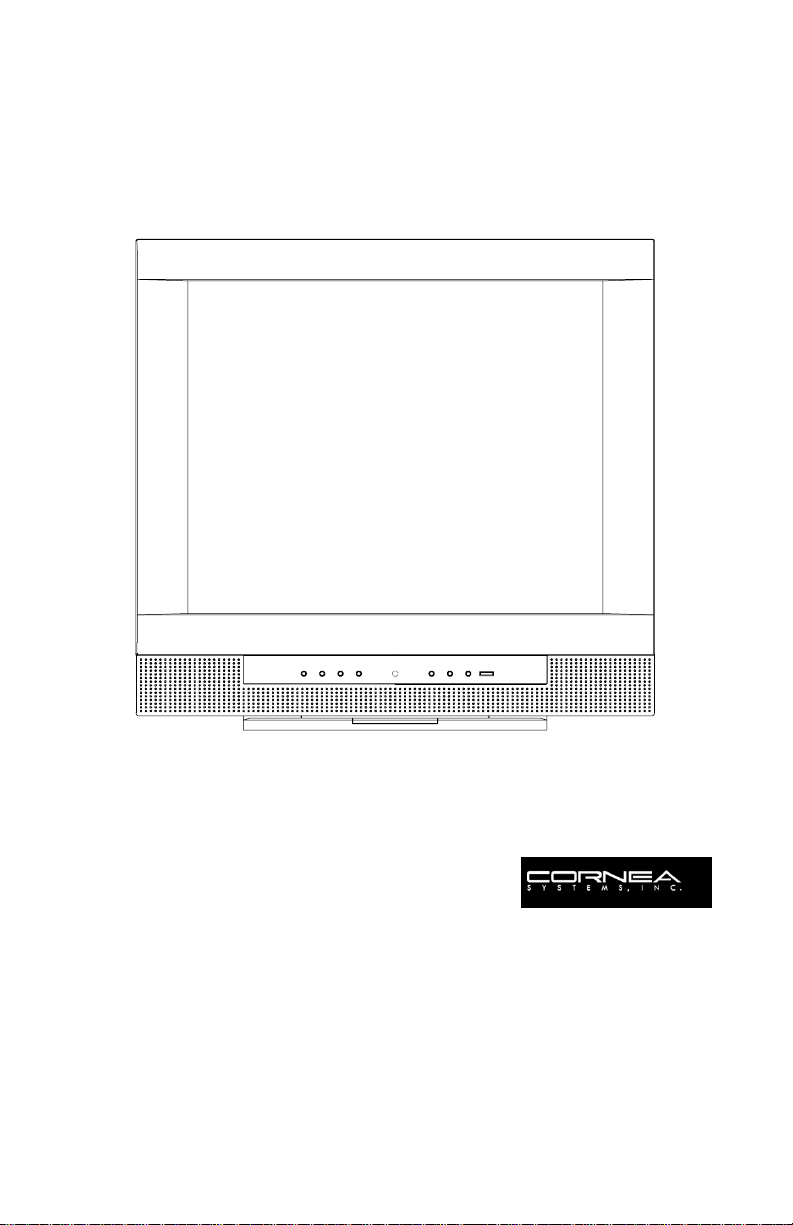
CT1503/CT1702
User Guide
Revision: 1-A
23 January 2002
Page 2

Congratulations!
Congratulations on your purchase of a state-of-the-art TFT
LCD Moni tor by Corn ea Systems, Inc.
We know you will be pleased with your investment and will
enjoy the dynamic viewing—You will never see images the
same again!
Our Monitor is easy to set up.
Just follow o ur s im ple instructions an d you w ill be vie w in g a
“new world ” in no time:
•
Connect
Configur e
•
Adjust
•
Enjoy
•
the Monitor to your PC, Tuner, DVD, VCR, etc.
/Set-up the Monitor
the display
!
Because your satisfaction is important to us, please contact
us if you have any questions.
We can be reache d at:
1-800-681-6155
Monday–Friday
8 a.m. – 5 p.m. (Pacific Time)
Copyright © 2002
Part Number: XXX XXXXXX
Revision: XX XXX
2
Page 3

Table of Contents
General Information
GENERAL INFORMATION: General Safety Precautions . . . . . . . . . . . . . . 5
GENERAL INF ORMATION: Unpacking Your Moni tor & Inventorying th e
Parts . . . . . . . . . . . . . . . . . . . . . . . . . . . . . . . . . . . . . . . . . . . . . . . . . . . . . . . 8
Figure 1: Inventory of Parts . . . . . . . . . . . . . . . . . . . . . . . . . . . . . . . . . . . . . . . . . . . . . . . . . .8
Component Information
COMPONENTS: The Ba ck of the Monitor (Connection Locations) . . . 10
Figure 2: CT1503 Connection Locations (Back-View of the Monitor) . . . . . . . . . . . . . . 10
Figure 3: CT1702 Connection Locations (Back-View of the Monitor) . . . . . . . . . . . . . . 11
COMPONENTS: The Front of the Monitor . . . . . . . . . . . . . . . . . . . . . . . . 12
Figure 4: CT1503/T1702: Front of the Monitor . . . . . . . . . . . . . . . . . . . . . . . . . . . . . . . . . . 12
Monitor Item Definition . . . . . . . . . . . . . . . . . . . . . . . . . . . . . . . . . . . . . . . . . . . . . . . . . . . .12
Adjusting the Tilt (or Viewing Angle) . . . . . . . . . . . . . . . . . . . . . . . . . . . . . . . . . . . . . . . . . 14
Power Management Function. . . . . . . . . . . . . . . . . . . . . . . . . . . . . . . . . . . . . . . . . . . . . . 14
COMPONENTS: The Remote Control. . . . . . . . . . . . . . . . . . . . . . . . . . . . 15
Figure 5: Remote Control Device. . . . . . . . . . . . . . . . . . . . . . . . . . . . . . . . . . . . . . . . . . . . 15
Remote Control Item Definition . . . . . . . . . . . . . . . . . . . . . . . . . . . . . . . . . . . . . . . . . . . . . 15
Connecting
CONNECTING: Your Monitor to Your Computer . . . . . . . . . . . . . . . . . . 17
Figure 6: Monitor-to-Computer Connection Diagram . . . . . . . . . . . . . . . . . . . . . . . . . . 19
CONNECTING: Your Monitor to a Tuner (TV/CATV). . . . . . . . . . . . . . . . 20
Figure 7: Tuner (TV/CATV)-to-Monitor Connection Diagram . . . . . . . . . . . . . . . . . . . . . 22
CONNECTING: Other External A/V Devices to Your Monitor . . . . . . . . 23
Figure 8: Monitor-to-External A/V Devices Connection Diagram . . . . . . . . . . . . . . . . . 25
Configuring/Adjusting
CONFIGURING & ADJUSTING the Display: PC (ANALOG) Mode. . . . . 26
Initial Set-Up & Adjustment of the Monitor . . . . . . . . . . . . . . . . . . . . . . . . . . . . . . . . . . . . 26
Explanation of Remaining Menu Items: PC (ANALOG) Mode . . . . . . . . . . . . . . . . . . . . 31
CONFIGURING & ADJUSTING the Display: TV/CATV (TUNER) Mode . . 34
Initial Set-Up & Adjustment of the Monitor . . . . . . . . . . . . . . . . . . . . . . . . . . . . . . . . . . . . 34
3
Page 4

Explanation of Remaining Menu Items: TV/CATV (TUNER) & S-VIDEO Modes . . . . . . . 37
CONFIGURING & ADJUSTING the Display: External Devices (S-VIDEO)
Mode . . . . . . . . . . . . . . . . . . . . . . . . . . . . . . . . . . . . . . . . . . . . . . . . . . . . . 39
Initial Set-Up & Adjustment of the Monitor . . . . . . . . . . . . . . . . . . . . . . . . . . . . . . . . . . . . 39
Explanation of Remaining Menu Items: TV/CATV (TUNER) & S-VIDEO Modes . . . . . . . 37
Troubleshooting
TROUBLESHOOTING: Resolution to Potential Problems . . . . . . . . . . . . . 41
Appendix
APPENDIX: Warranty . . . . . . . . . . . . . . . . . . . . . . . . . . . . . . . . . . . . . . . . . 43
APPENDIX: CT1503 Analog Display Modes (Analog) . . . . . . . . . . . . . . 47
APPENDIX: CT1702 Display Modes (Analog) . . . . . . . . . . . . . . . . . . . . . 48
APPENDIX: CT1703 Display Modes (Digital) . . . . . . . . . . . . . . . . . . . . . . 49
4
Page 5
GENERAL INFORMATION: General Safety Precautions
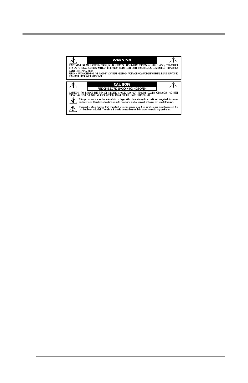
GENERAL INFORMATION: General Safety Precautions
This Monitor has bee n engin eer ed an d ma n u fact ured t o assur e you r
safety.
MPORTANT
I
To avoid electrical shock and to prevent other injuries or
damage, pleas e read t his Man ual an d comp ly with the st ated
warnings and procedures.
:
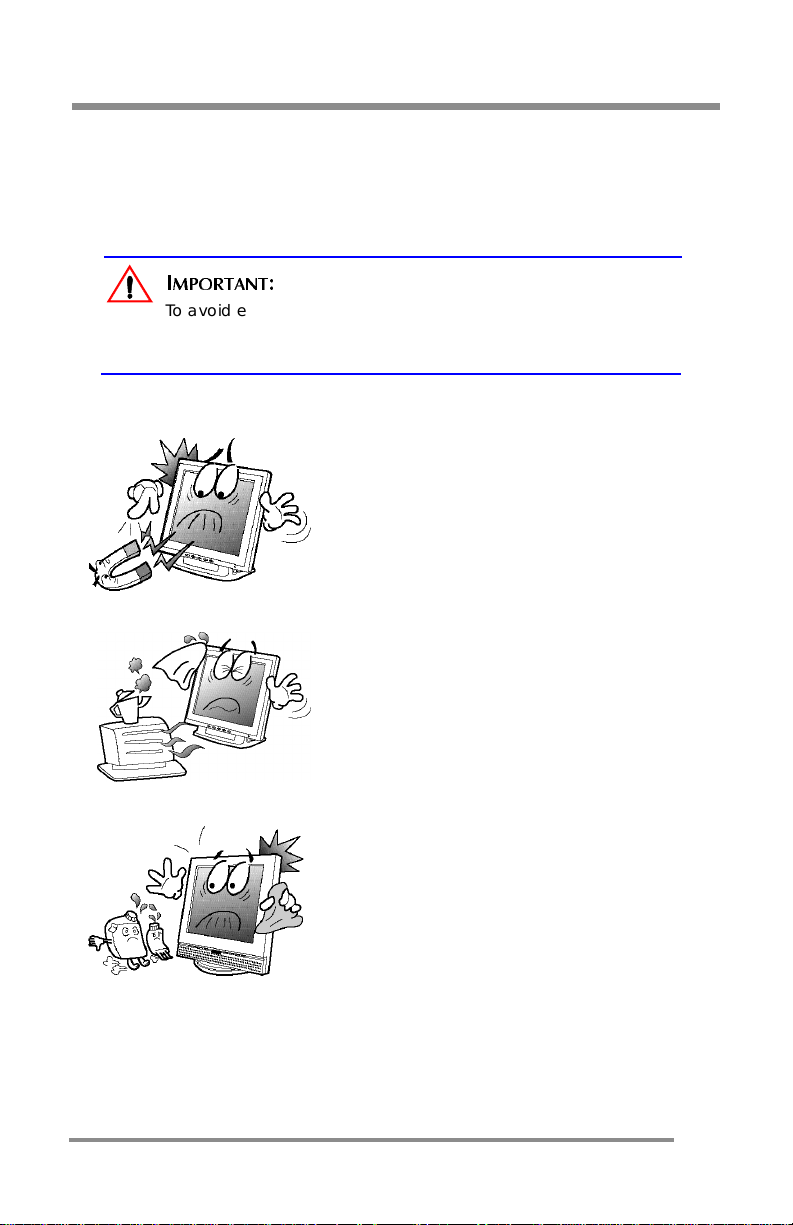
Foreign & Magnetic Objects
•Do not plac e anyt hing he av y, wet or
magnetic on the Mo nitor or Power Cord.
•Do not cover the ventilation openings or
touch them with metallic or flammable
material.
Temperature
•Extreme temperature may ca use
discoloration or damages.
•Avoid operating the Monitor in extreme heat,
humidity, or dusty areas.
•Ambient Temperature: 0°C– 40°C
Cleaning the LCD Surface
•To prevent any damage to the LCD surface:
O NOT
•D
•Instead, use a damp soft cloth.
use solvents, (such as benzene).
5
Page 6
GENERAL INFORMATION: General Safety Precauti on s
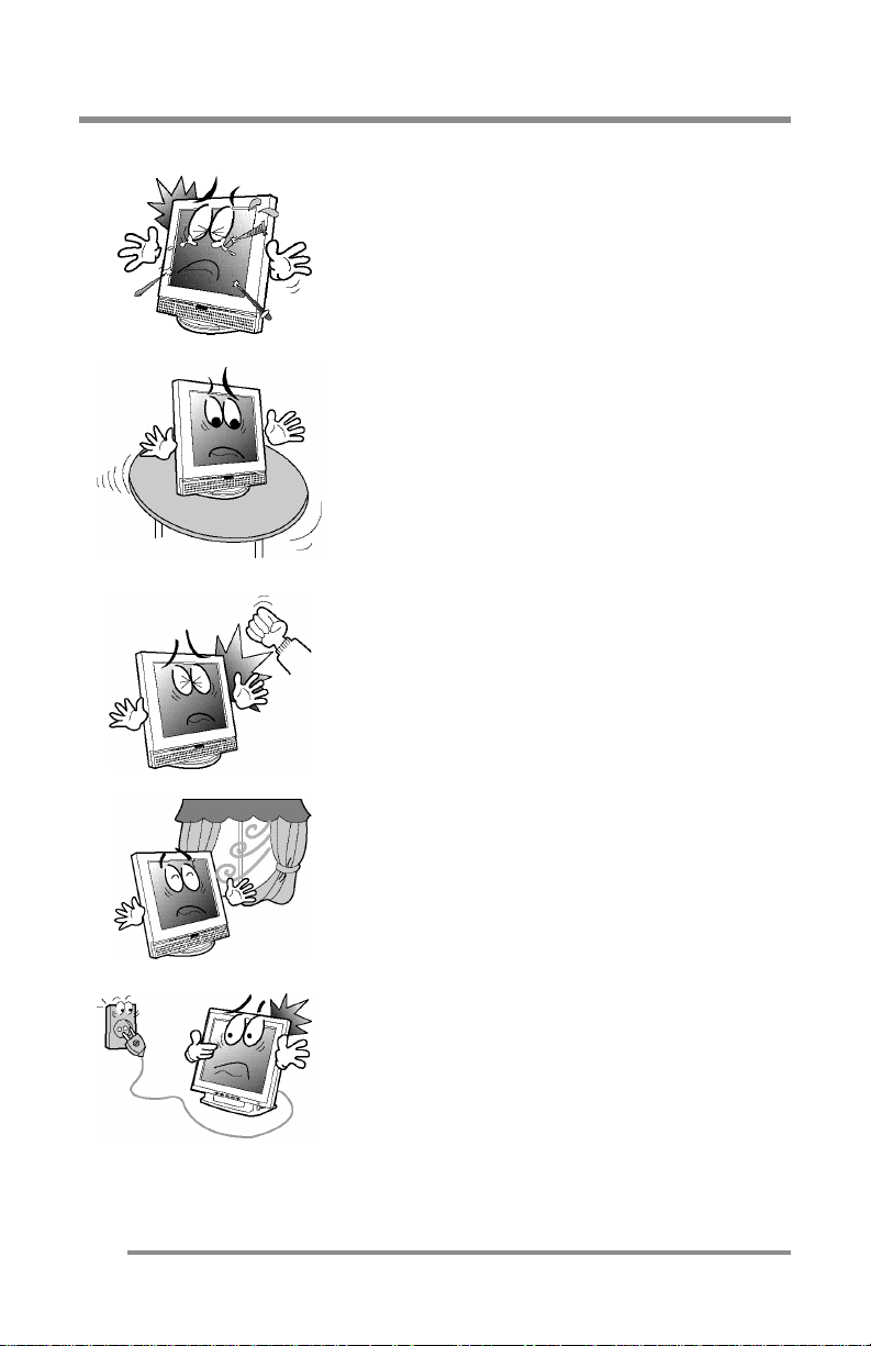
Proper Tools
•To prevent any scratches to the LCD surface,
DO NOT
use small tools (such as a pin or a
pencil) near the Monitor.
Flat, Sturdy Surface
•Place th e Monito r on a sturdy, flat surfa c e to
prevent it from falling.
External Shocks
NOT
•DO
hit, drop, or otherwise apply any
mechanical or physical shocks to the Monitor.
Ventilation
•Install the M o nito r in a we ll-ve nt ila te d ar ea.
•NOTE: Be sure the ve nt ilati o n is not so stro ng
that blows over the Monitor.
Power Off
•Turn the Monitor
the power outlet or surge protector.
•Also, while installing your Monitor, it is wise to
unplug your Computer and other
compon ents from the power outlet.
before connecting it to
OFF
6
Page 7
GENERAL INFORMATION: General Safety Precautions
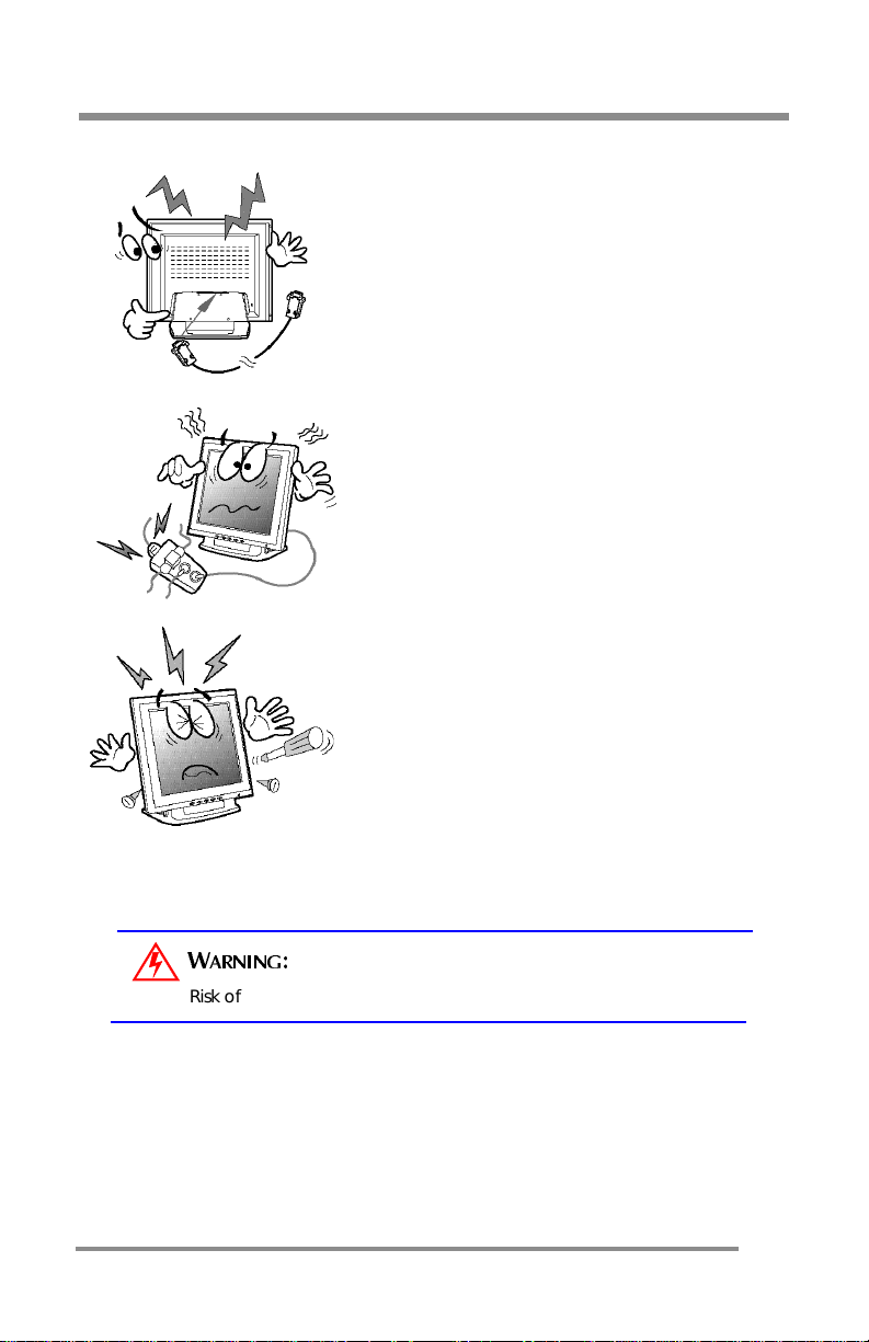
Secure Connections
•Make sure that the Monit or’s Power Cord and
the other devices’ power cords are properly
connected.
Other Electrical Safety Notes
•Overloa ding A C outl ets and e xte nsi o n cords
are dangerous.
•Also, frayed Power Cords and the broken
plugs may cause electric s hock or fire.
Do Not Open the Monitor
•There are no user-serviceable components
inside.
•There is a risk of exposure to high-voltage
electricity inside, even when power is turned
.
OFF
•If the Monitor does not operate properly,
unplug th e Power Cord and cont act you r
dealer or Technical Support.
• Handling the electrical equipment carelessly
may cause electri cal shock a n d other
hazards.
ARNING
W
Risk of electrical shock. DO NOT OPEN the Monitor.
:
7
Page 8
GENERAL INFORMATION: Unpacking Your Monitor & Inventorying the Parts
GENERAL INFORMATION:
Unpacking Your Monitor & Inventorying the Parts
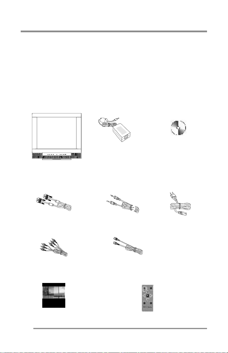
Please make sure the parts shown in the following figure are included with
your Monitor.
If any of these items are missing or appear damaged, contact your dealer
or call Technical Support immediately.
Figure 1: Inventory of Parts
Installation CD
Power Cord
Remote Control
CT1503/CT1703
Monitor
15-Pin VGA
Signal Cable
RCA Cable
USER MANUAL
AC/DC
Power Adapter
Audio Cable
S-Video Cable
User’s Manual
8
Page 9
GENERAL INFORMATION: Unpacking Your Monitor & Inventorying the Parts
OTE
N
:
Depending on the voltage requirements for your
area, the Power Cord may be different than what
is indicated in the fig ure.
When
When
unpacking
• Carefully open the box.
• Lay the box flat on a tabl e and car efull y slide the contents out
• Do not “dump” the contents out of the box.
inspecting
• Verify all the components are present, according to the
• Verify the parts are not da ma ged .
the Monitor and its components:
of the box.
MPORTANT
I
DO NOT remove the protective plastic cover from the Monitor.
This cover protects the screen during Installation, and will be
remo ve d when the In st a l l ation is com p le t e .
previous f i g u re.
:
the Monitor and its components:
TIP:
Save the box and other packing material in case the
Monitor ne eds to be retur ned.
9
Page 10
COMPONENTS: The Back of the Monitor (Connection Locations)
COMPONENTS:
The Back of the Monitor
(C
ONNECTION LOCATIONS
)
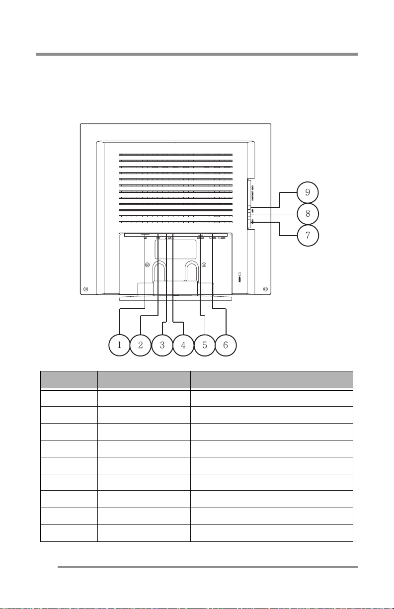
Figure 2: CT1503 Connection Locations
Number Abbreviation Definition
1 VGA 15-Pin Connector for D-Sub (Analog)
2 PWR AC/DC Adapter Connection
(Back-View of the Monitor)
10
3 OUT AUD Sound Out Connection
4 AUD IN Sound In Connection
5 ANTENNA Tuner (TV/CATV) Connection
6 S-VIDEO S-Video In put Connectio n
7 VIDEO Video Input Connection (Yellow)
8 L AUD Stereo Au d io Left Conne cti o n ( White)
9 AUD R Stereo Audio Right Connection (Red)
Page 11
COMPONENTS: The Back of the Monitor (Connection Locations)
10
8 5 6 4 3 2 1
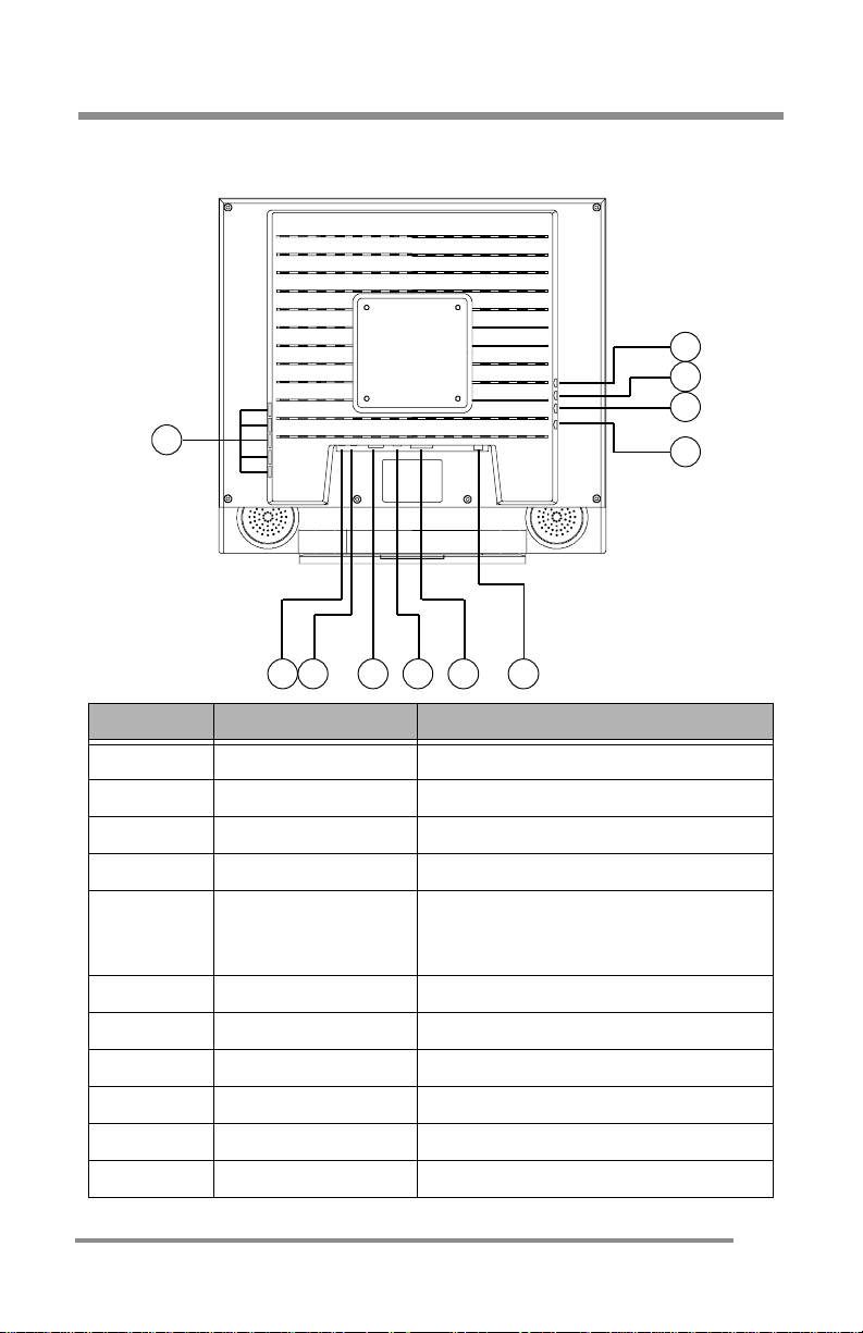
Figure 3: CT1702 Connection Locations
(Back-View of the Monitor)
Number Abbreviation Definition
1 OUT AUD Sound Out Connection
2 AUD IN Sound In Connection
3 VGA 15-Pin Connector for D-Sub (Analog)
4 PWR AC/DC Adapter Connection
Digital Vid eo Interface C o nnector
5DVI
6 ANTENNA Tuner (TV/CATV) Connection
7 S-VIDEO S-Video In put Connectio n
8 VIDEO Video Input Connection (Yellow)
9 L AUD Stereo Au d io Left Conne cti o n ( White)
10 AUD R Stereo Audio Right Connection (Red)
11 USB USB Port (Optional)
(To be used if the computer has a
digit al VGA card . )
11
Page 12
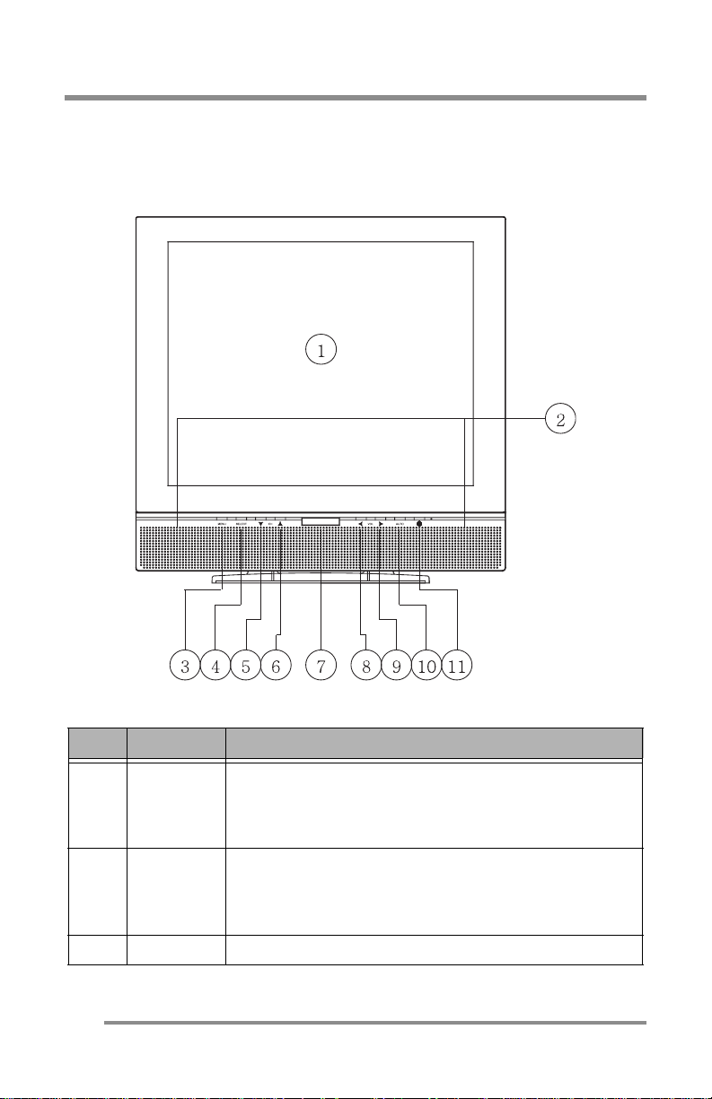
COMPONENTS: The Front of the Monitor
COMPONENTS: The Front of the Monitor
Figure 4: CT1503/T1702: Front of the Monitor
Monitor Item Definition
Item Item Definition
CT1503: 15” TFT LCD, max. res olutio n 1024 x 768, 16.2M
LCD Pane l
1
2
3 MENU Pressing this button displays the Main Menu.
(screen)
Built-In
Speakers
color (true color).
CT1702: 17” TFT LCD, max. resolution 1280 x 1024, 16.7M
color.
After conne cting the audio inp ut, y o u can use th e
speakers:
•CT1503: 2W output
•CT1702: 3W output
12
Page 13
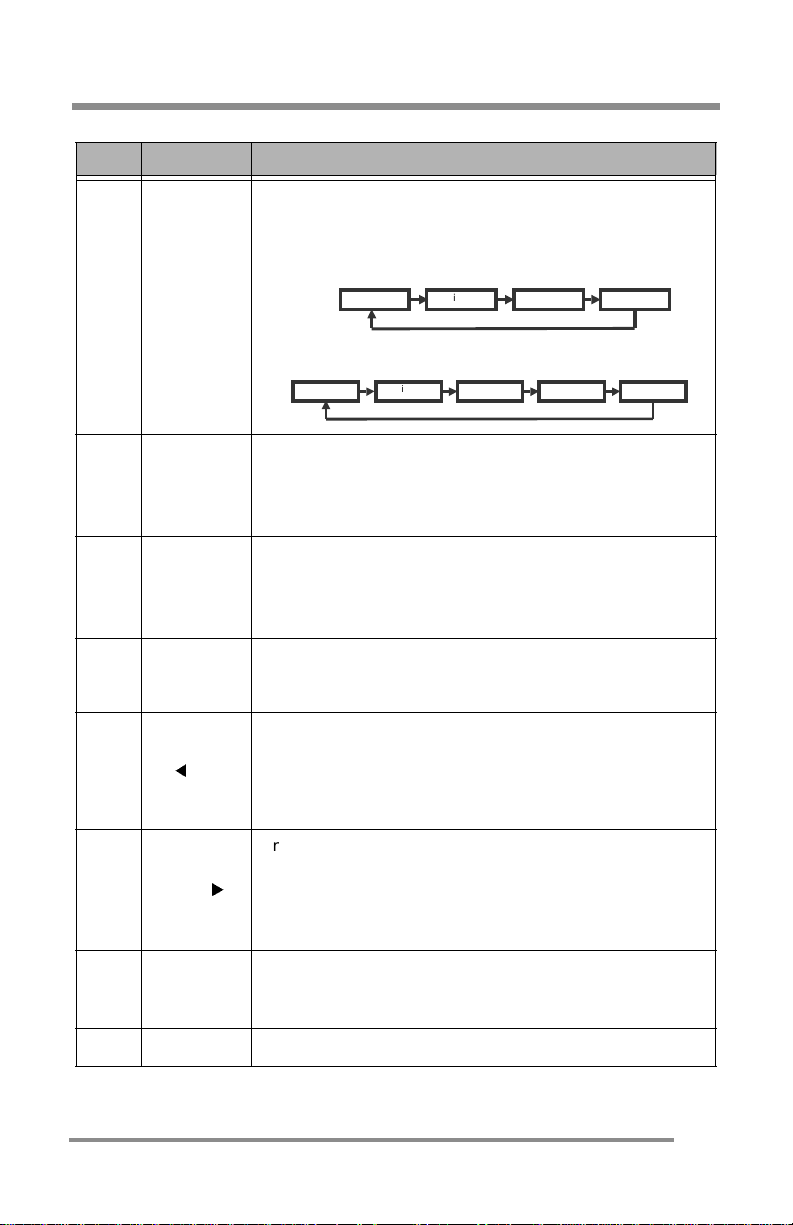
COMPONENTS: The Front of the Monitor
Item Item Definition
Pressing this butt on :
•Selects the highlighted menu item
•Selects the desired Input Source.
CT1503 Input Sourc e Opti o ns / Sc r o ll S eq ue nce:
4 SELECT
CT1702 Input Sourc e Opti o ns / Sc r o ll S eq ue nce:
Digital S-Video Tuner Analog
Digital Composite S-Video Tuner Analog
▼ CH
5
(Channel
Down)
▲ CH
6
(Channel
Up)
Remote
7
Control
Sensor
8
9VOL
VOL
10 AUTO
Pressing this butt on :
•All Input Sourc es: Mov es to the next lo we r menu
item.
•TV (Tuner ) : Sel e ct s the n ex t low e r channel.
Pressing this butt on :
•All Input Sourc es: Mov es to the n ext highe r m en u
item.
•TV (Tuner): Selects the next higher channel.
This sensor receives the signal from the Remote Control
device.
Pressing this butt on :
•Decreases the volume.
•In the MENU mode, decreases the value of the
parameter displayed or changes the displayed
option.
Pressing this butt on :
•Increases the volume.
•In the MENU mode, increases the value of the
parameter displayed or changes the displayed
option.
PC (Analog): A ctivates the auto adjustment functi on.
This function automatically adjusts the image’s position on
the LCD.
11 POWER
Pressing this button, turns the Monitor ON or OFF.
13
Page 14
Adjustin g the Tilt (or Viewing Angle)
Adjusting the Tilt (or Viewing Angle)
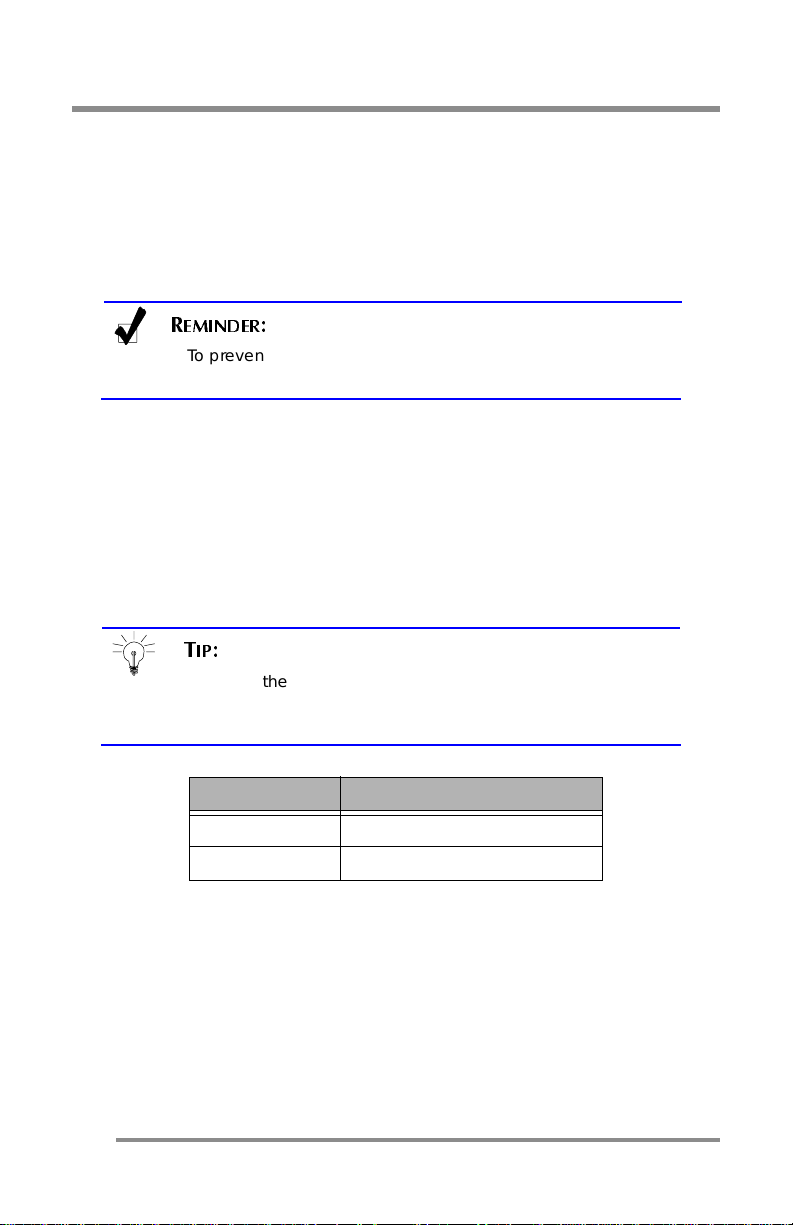
Your Monitor was designed to all ow you to adjust it to a comfortable
viewing angle.
The Monitor can be tilted forward 45
EMINDER
R
To prevent the Monitor from falling over, make sure it is
within the “s afe” viewing ang le range.
:
o
or back 90o.
Power Management Function
This Monitor is equipp ed w i th a DPMS ( Dis play Pow er Manage m ent
Signaling) function that automatically cuts the power dissipation down to
less t h an 5W when the computer is left unattended.
TIP:
Although the Monitor can be left in power-saving mode for
longer periods, we recommend that you turn it off after your
daily work.
Light Status Definition
Green Power ON.
14
Amber Power saving mode enabled.
Page 15
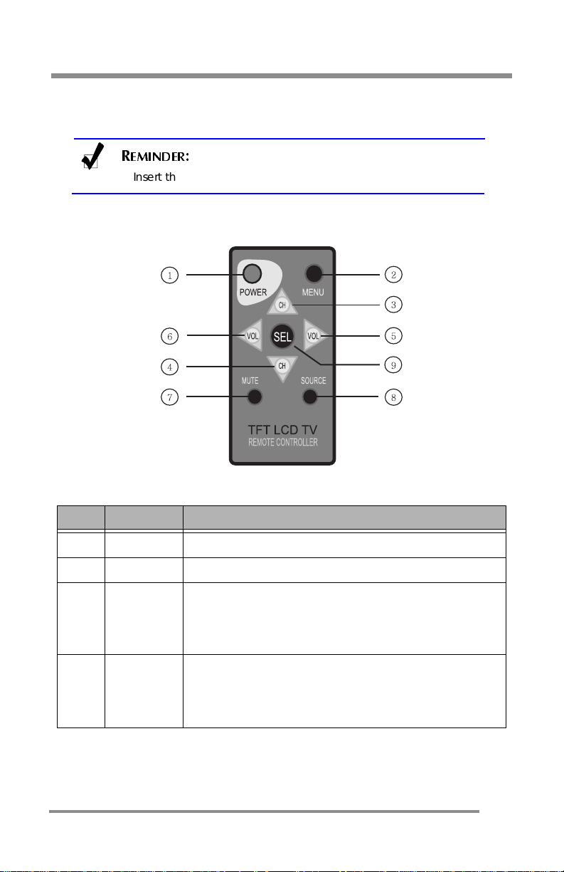
COMPONENTS: The Remote Control
COMPONENTS: The Remote Control
EMINDER
R
Insert the b a ttery into the Remote Cont rol .
Figure 5: Remote Control Device
:
Remote Control Item Defini ti on
Item Item Definition
1POWER
2 MENU Pressing this item displays the Main Menu.
▲ CH
3
(Channel
Up)
▼ CH
4
(Channel
Down)
Pressing this item, turns the Monitor ON or OFF.
Pressing this item:
•All Input Sources: Moves to the next higher menu
item.
•TV (Tune r): Selec ts the ne xt hig he r chan nel.
Pressing this item:
•All Input Sources: Moves to the next lower menu
item.
•TV (Tuner): Selects the next lower channel.
15
Page 16
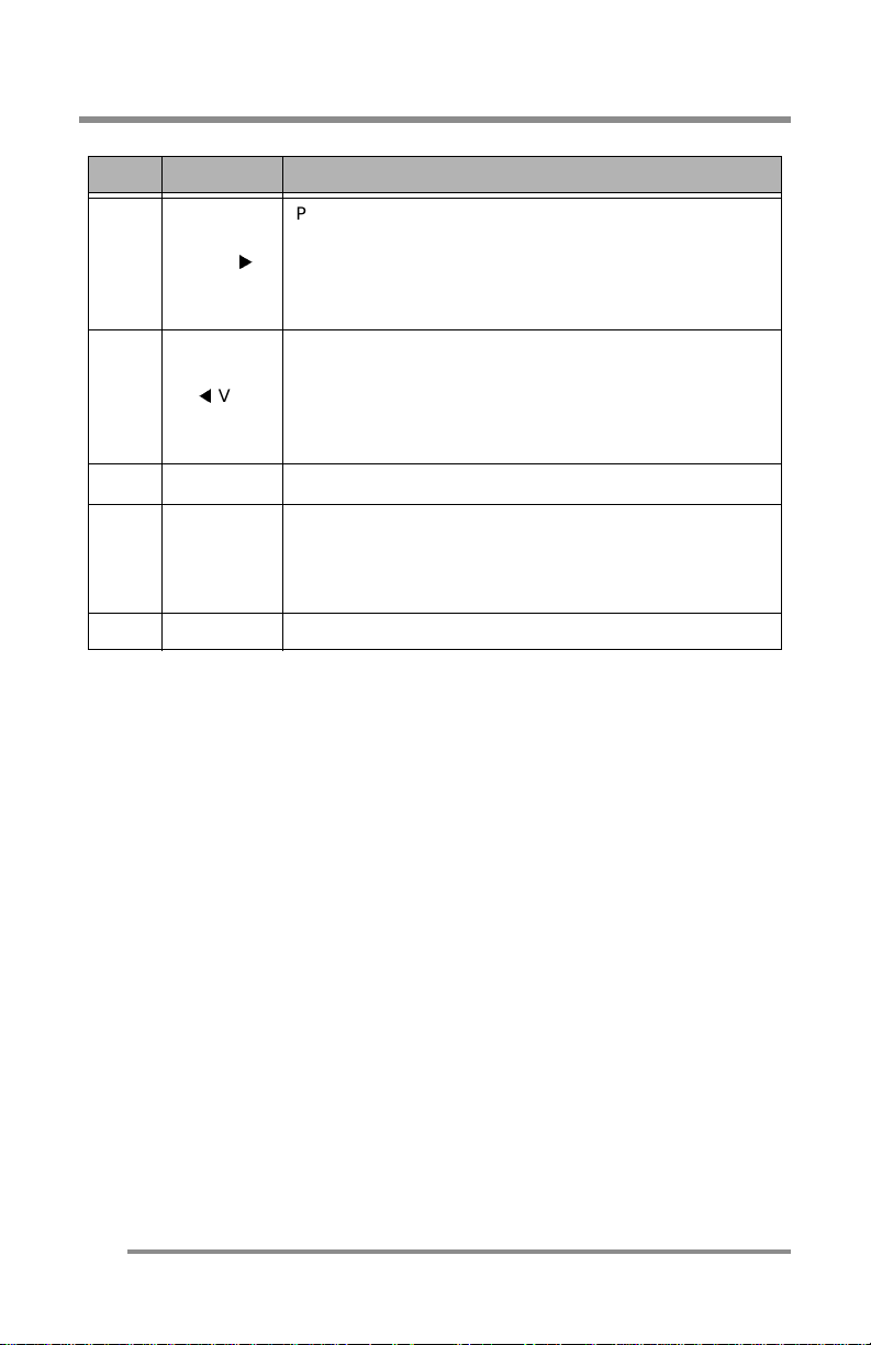
COMPONENTS: The Remote Control
Item Item Definition
Pressing this item:
•Increases th e volume.
5VOL
6
VOL
Pressing this item:
•In the MENU mode, increases the value of the
parameter displayed or changes the option
displayed.
•Decreases the volume.
•In the MENU mode, decreases the value of the
parameter displayed or changes the option
displayed.
7MUTE
8SOURCE
9 SELECT Pressing this item, selects the highlighted menu item.
Pressing this item turns the sound ON or OFF.
Pressing this item scrolls through the available Input
Sources.
The Input Source’s name displays briefly in the upper
right-hand corner of the screen.
16
Page 17
CONNECTING: Your Monitor to Your Computer
CONNECTING: Your Monitor to Your Computer
and
1. Turn
2. Carefully unpack all the components and verify all the parts are
3. Organize the cables you need an d familiarize yourself w ith the
4. With the Monitor laying screen-side down on a smooth, clean surface,
OFF
present and undamaged.
connection configuration.
CT1702, see pages 11 & 19.)
flip open the Monitor base.
UNPLUG
your C omputer until instructed otherwise.
(See pa ge 8.)
(For the CT1503, see pages 10 & 19. For the
TIP:
For easier access to the cable connections, keep the
Monitor laying (screen-side down) on a smooth surface.
Connect the 15-pin VGA Cable to the Monitor’s “VGA”
5.
6. Connect the 15-pin VGA Cable to your Computer.
EMINDER
R
Using your fingers, hand-tighten th e sc rews o n the 15-Pin
connectors.
Plug the Audio Cable into the Monitor’s “AUD IN”
7.
:
connector.
connector.
OTE
N
:
To use a headset, plug the headset into “AUD
OUT” connector on the Monitor.
8. Connect the Audio Cable to your Computer at the speake r card
location.
9. If you
are not
VCR), continue with the r emaining steps.
If you are connecting other components to the Monitor, continue to
the next appropriately labeled “CONNECTING” section.
connecting any more components (e.g. CATV, DVD or
17
Page 18
CONNECTING: Your Monitor to Your Computer
10. Connect the round AC/DC Adapter Plug to the Monitor’s “PWR”
connector.
11. Connect the Power Cord to the AC/DC Adapter.
EMINDER
R
Do not
protector yet.
:
plug the Power Cor d int o the wa ll outl e t/ surge
Stand up your Monitor and adjust it
12.
13. Plug in the Power Cords for both the Monitor and Computer to the wall
power outlet or surge protector.
14. Turn
Remove the plastic protective cover
15.
16. Pressing either the SELECT button on the front of the Monitor
or the S OURCE button on the Remo te Control
ANALOG Input Source option.
17. Insert the Set-up Disk into your Computer’s CD slot and follow the
instructions on page 27.
18. If necessary, fine-tune the display by using the On Screen D i splay
(OSD) menus (image position, brightness, and other items).
(See page 26.)
19. Enjoy your new Monitor from Cornea Systems, Inc.!
both the Monitor and Computer.
ON
EMINDER
R
Insert the b a ttery into the Remote Cont rol .
:
for proper viewing.
from the front of the Monitor.
(page 15)
(See page 14.)
(page 1 2)
, scroll to the
TIP:
Save the original container and the packing materials in
case there are difficulties and you need to return the
Monitor.
18
Page 19
CONNECTING: Your Monitor to Your Computer
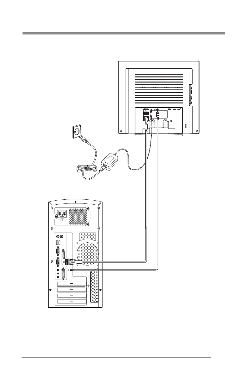
Figure 6: Monitor-to-Computer Connection Diagram
19
Page 20
CONNECTING: Your Monitor to a Tuner (TV/CATV)
CONNECTING: Your Monitor to a Tuner (TV/CATV)
1. Carefully unpack all the components and verify all the parts are
present and undamaged.
2. Organize the cable(s) you need and familiarize yourself with the
connection configuration.
(For the C T1503, see p ages 10 & 22. For the CT1702, see pages 11 & 22. )
3. With the Monitor laying screen-side down on a smooth, clean surface,
flip open the Monitor base.
TIP:
For easier access to the cable connections, keep the
Monitor laying (screen-side down) on a smooth surface.
Connect the Antenna
4.
antenna) into the Monitor’s “ANTENNA” connector.
EMINDER
R
The Antenn a co nnection shou ld b e hand-tight.
:
(See pa ge 8.)
(from your Cable TV or external/internal
Connect the
5.
connector.
6. Connect the Power Cord to the AC/DC Adapter.
EMINDER
R
Do not
protector yet.
7. If you are not connecting any more components (e.g. DVD or VCR),
continue with the r emaining steps.
If you are connecting other components to the Monitor, continue to
the next appropriately labeled “CONNECTING” section.
8. Stand up your Monitor and adjust it for proper viewing.
AC/DC Adapter Plug
round
to the Monitor’s “PWR”
:
plug the Power Cor d int o the wa ll outl e t/ surge
(See page 14.)
20
Page 21
CONNECTING: Your Monitor to a Tuner (TV/CATV)
9. Plug in the Power Cord for the Monitor to the wall power outlet or surge
protector.
10.
Turn
the Monitor
ON
.
11. Remove the plastic protective cover from the front of the Monitor.
12. Pressing either the SELECT button on the front of the Monitor
or the S OURCE button on the Remo te Control
(page 15)
(page 1 2)
, scroll to the
TUNER Input Source option.
EMINDER
R
Insert the b a ttery into the Remote Cont rol .
13. Using the On Screen Display (OSD) menus,
antenna type
:
(See page 35.)
.
select the
appropriate
14. If necessary, configure the Tuner to automatically search for the
channels.
(See page 31.)
15. If necessary, fine-tune the display by using the OSD menus (image
position, brightness, and other items).
(See pages 35–37.)
16. Enjoy your new Monitor from Cornea Systems, Inc.!
TIP:
Save the original container and the packing materials in
case there are difficulties and you need to return the
Monitor.
21
Page 22
CONNECTING: Your Monitor to a Tuner (TV/CATV)
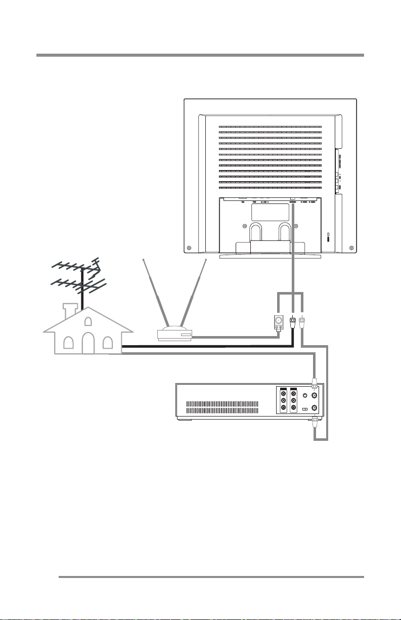
Figure 7: Tuner (TV/CATV)-to-Monitor Connection Diagram
Connecting
indoor antena
Connecting
outdoor antenna
22
Connecting antenna by way of VTR
Page 23
CONNECTING: Other Exte rnal A/V Devices to Your Moni tor
CONNECTING: Other External A/V Devices to Your
Monitor
1. Carefully unpack all the components and verify all the parts are
present and undamaged.
2. Organize the cable(s) you need and familiarize yourself with the
connection configuration.
(For the C T1503, see p ages 10 & 25. For the CT1702, see pages 11 & 25. )
3. With the Monitor laying screen-side down on a smooth, clean surface,
flip open the Monitor base.
TIP:
For easier access to the cable connections, keep the
Monitor laying (screen-side down) on a smooth surface.
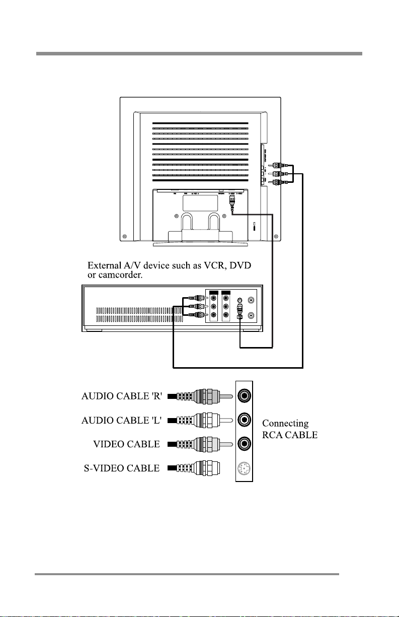
4. At the side of the Monitor, connect the RCA Cable and/or the S-Video
Cable, to the “AUD L”, “AUD R”, “VIDEO” and “S-VIDEO” l ocations, as
appropriate.
5. Connect the round AC/DC Adapter Plug to the Monitor’s “PWR”
connector.
(See pa ge 8.)
Connect the Power Cord to the AC/DC Adapter
6.
EMINDER
R
Do not
protector yet.
7. If you are not connecting any more components (e.g. Tuner/
Antenna), continue with the remaining steps.
are
If you
the next appropriately labeled “CONNECTING” section.
8. On the external A/V device(s), if not don e already, connect the RCA
Cable and/or the S-Video Cable
“AUD R”, “VIDEO” and “S-VIDEO” locations, as appropriate.
Stand up your Monitor and adjust it
9.
connecting other components to the Monitor, continue to
:
plug the Power Cor d int o the wa ll outl e t/ surge
, to the corresponding
for proper viewing.
.
OUT
“AUD L”,
(See page 14.)
23
Page 24
CONNECTING: Other External A /V Devices to Your Monitor
10. Plug in the Power Cord for the Monitor and other A/V devices to the
wall power outlet or surge protector.
Turn
11.
12. Remove the plastic protective cover from the front of the Monitor.
13. Pressing either the SELECT button on the front of the Monitor
or the S OURCE button on the Remo te Control
S-VIDEO or COMPOSITE Input Source option, whichever is appropriate
for your system.
14. If necessary,
(OSD) menus (image position, brightness, and other items).
(See page 39.)
Enjoy your new Monitor
15.
the Monitor and other A/V devices
ON
EMINDER
R
Insert the b a ttery into the Remote Cont rol .
:
fine-tune the display
from Cornea Systems, Inc.!
by using th e On S creen Displa y
, as appropriate.
(page 15)
, scroll to the
(page 1 2)
TIP:
Save the original container and the packing materials in
case there are difficulties and you need to return the
Monitor.
24
Page 25
CONNECTING: Other Exte rnal A/V Devices to Your Moni tor
Figure 8: Monitor-to-External A/V Devices Connection Diagram
25
Page 26
CONFIGURING & ADJUSTING the Display: PC (ANALOG) Mode
CONFIGURING & ADJUSTING the Display: PC (ANALOG)
Mode
Using the system’s On Screen Displays (OSD), you can adjust and refine
your Monitor’s image.
The following table describes the initial set-up steps and the other menus
available.
Remember,
when using the buttons on the front o f your Monitor
• Pres s the MENU butt on to display the Main Menu.
▲ ▼
• Use the CHANNEL
buttons to scroll through the menu
items.
• Press the SELECT button to choose the desired menu item
to store the new value/parameter.
• Use the VOLUME
buttons to increase/decrease the
value/parameter.
Initial Set-Up & Adjustment of the Monitor
Select the Input Source Mode
1. After all the connectio ns are
made, turn ON both the Computer
and the Monitor.
2. Select the Input Sourc e mode by
using
either
the Remote Co ntrol:
•Pres sing (repeatedl y) the
SOURCE button
OR
The buttons on the fr ont of the
Monitor by:
•Pressing the SELECT button
(repeatedly) to scroll thro ugh
the various Input Source
modes
OR
•From the Main Menu, choose
the SELEC T INP U T (CT 15 03) /
SETUP option (CT1702 ).
3. Select the ANALOG mode .
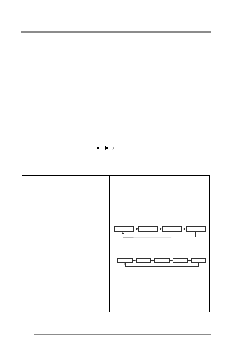
CT1503 Input Source Scroll Sequence:
CT1702 Input Source Scroll Sequence:
:
and
Digital S-Video Tuner Analog
Digital Compos ite S-Video Tu ne r Analog
26
Page 27

CONFI G UR ING & ADJU S TI N G th e Display : P C (ANALO G ) M o de
Install the TFT LCD Monitor Driver.
4. If previously done, skip this section.
previously done, install the INF file on your PC by performing the following:
If not
a. Insert the I nstallation Dis k into your Computer’s CD disk drive.
Either
b.
c. With the left mo use bu tton, click on the “Properties” selection to open the
d. Click the “Setting” tab and click the “Advanced Properties” tab.
e. Click the “Monitor” tab and select “Change”.
f. Click on the “Display the list of all the drivers in specific location…”
g. Sel e ct “CD disk drivers”, for example select from the F-drive, the “INF file”
h. Click on the INF file (LCD.inf) on the Installation Disk and select proper size
i. When the driver files are insta lled to the hard drive, cli ck “OK” and press
j. Click “Yes” when prompted to accept the new “Refresh Rate” setting.
follow the “Add New Hardware” wizard or at the Windows 95/98/
2000 desktop (initial screen), click the right mouse button to open a “popup” menu.
“Display Properties” menu.
select ion, then click on the “Have Disk”, and then, click on the “Browse
File” button.
folder.
of this Mo ni to r.
• The size of this Monitor is stated on page 17 of this Manual.
“Close” to save settings.
To Change the Resolution or Refresh Rate:
a. At the Windo ws 95/9 8/ 200 0 de sk top (i niti al sc ree n) , clic k the right mouse
button to open a “pop-up” menu.
b. With the left mouse button, click on “Properties” to open the “Display
Properties” menu.
c. Click on the “Setting” tab and change the resolution you what you want.
d. Click “Apply” or “OK” button, then click “OK” to keep the selected
resolution.
e. Go back to “Display Properties” menu and click on the “Setting” tab.
Select the “Advanced Properties” button and then click on “Adapter”.
f. In “Adapter Properties”, select “Refresh Rate” to change it.
•Our Monitors support a refresh rate up to 75Hz. For the best possible
display,
• If you do not ha ve this option , try th e procedure agai n af ter installing
the Monitor driver.
we recommend a refresh rate of 60Hz.
27
Page 28
CONFIGURING & ADJUSTING the Display: PC (ANALOG) Mode
Adjust the Initial Image:
Vertical & Horizontal Alignme nt
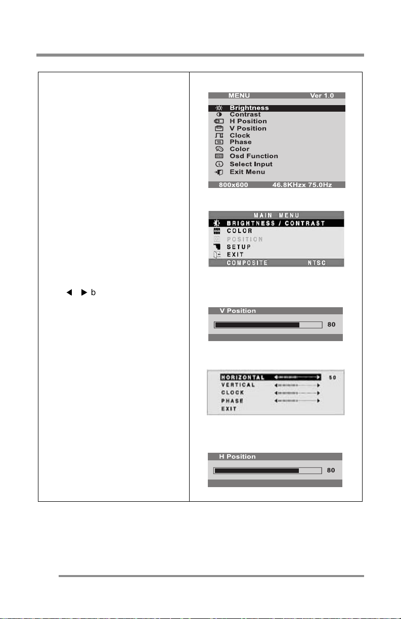
7. If necess ary, at the initial display,
adjust the VERTICAL position of the
display by:
•Pressing the MENU button to
display the Main Menu.
•Pressing the CHANNEL ▲ ▼
buttons (repeatedly) to scroll
to the V POSITION (CT1503) or
the POS I TIO N (C T1702) o p ti on.
• Press the SELECT button to
select the menu item.
•CT170 2: Use th e CHANN EL ▲ ▼
buttons (repeatedly) to scroll
to the VERTICA L opti o n on the
sub-menu.
•At the V POSITIO N o r VER TICA L
sub-menu, use the VOLUME
buttons to move the
image up or down until it is
centered vertically on the
display.
•Once you have vertically
centere d th e d is pl ay, press th e
SELECT button.
CT1503 M ai n Menu:
CT1702 M ai n Menu:
CT1503 Ve r ti c al P o sit io n Sub-Menu:
CT1702 P osi ti on Sub -me nu:
8. Now, center the display
HORIZONTALLY by:
•Repeating same general
procedure for the vertical
adjustment, but by selecting
the H POSITION (CT1503) or the
HORIZ ONT A L (C T1 70 2) o pt io n
instead.
•Remember to press the SELECT
button when the display is
centered horizontally.
28
CT1503 H or izo nt a l Posi ti on Displ ay:
Page 29
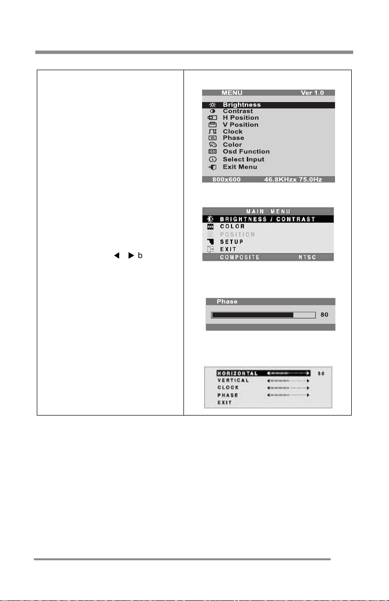
CONFI G UR ING & ADJU S TI N G th e Display : P C (ANALO G ) M o de
Adjust the Clarity of the Image:
Phase
9. If necessary, adjust the clarity of
the image by:
•Pressing the MENU button to
display the Main Menu.
•Pressing the CHANNEL ▲ ▼
buttons (repeatedly) to scroll
to the PHAS E (CT1 50 3) or the
POSITION (CT1 70 2) optio n.
• Press the SELECT button to
select the menu item.
•CT170 2: Use th e CHANN EL ▲ ▼
buttons (repeatedly) to scroll
to the PHASE option.
•At the PHAS E sub -me nu, use
the VOLUME
adjust the clarity of the image.
•Once you have the image set
to your liking, press the SELECT
button.
buttons to
CT1503 M ai n Menu:
CT1702 M ai n Menu:
CT1503 P ha s e Sub -Menu:
CT1702 P osi ti o n Sub -Menu:
29
Page 30
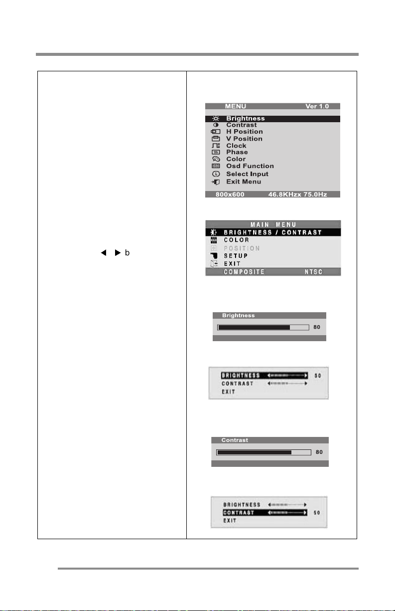
CONFIGURING & ADJUSTING the Display: PC (ANALOG) Mode
Adjust the Brightness & Contrast
Brightness
•Controls th e over all im age a nd
background screen brightness.
10. Press the ME NU button to di splay
the Main Me nu.
11. Pressing the CHANNEL ▲ ▼
buttons (repeatedly), scroll to the
BRIGHT N E SS (CT1503) or the
BRIGHTNESS/CONTRAST (CT1702)
item.
12. Press the SELECT button to choose
the desired item.
13. At the appropriat e sub-men u, use
the VOLUME
adjust the brightness of the image.
14. Onc e y ou ha ve th e br ig h tn es s set
to your liking, press the SELECT
button.
buttons to
CT1503 M ai n Menu:
CT1702 M ai n Menu:
CT1503 Bri ghtness Sub-Me nu:
CT1702 Bri ghtness Sub-Me nu:
Contrast
•Contro ls the i ma ge brightne ss
in relation to the background.
15. Repeat the same general
procedure for the brightness
adjustment, but by selecting the
CONTRAST (CT1503) or the
BRIGHTNESS/CONTRAST (CT1702)
option instead.
16. Once you have the contrast set
to your liking, press the SELECT
button.
CT1503 C o ntra s t Su b-M e nu :
CT1702 C o ntra s t Su b-M e nu :
30
Page 31
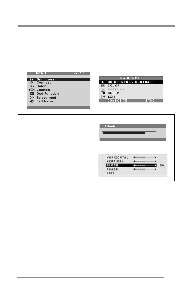
Explanation of Remaining Menu Items: PC (ANALOG) Mode
Explanation of Remaining Menu Items: PC (ANALOG)
Mode
The following table describes the other menus available.
Figure 9: The Main Menus for the CT1503 and the CT1702, respectively:
CLOCK
•Performs a rough image tuning
by screen size adjustment.
•CT1702: The CLOCK sub-menu
is obtained via the POSITION
item on the Main Menu.
CT1503 C l ock S ub - Me nu:
CT1702 C l ock S ub - Me nu:
31
Page 32
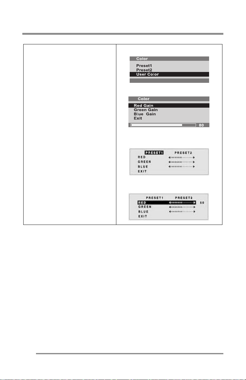
Explan a t ion of Rem ai n ing Menu I te m s: PC (ANA L O G) Mode
COLOR
•Fine-tunes the image viewing.
Preset 1
•Bluish Whit e
Preset 2
•Plain White
User Color (CT1503 only)
•Controls the individual colors of
Red, Green, and Blue .
Exit (CT1702 only)
•Closes this sub-menu and
returns to the Main Me nu.
CT1503 Co lo r Sub - M enu:
CT1503 User Color Sub-Menu:
CT1702 Co lo r Sub - M enu:
CT1702 User Color Sub-Menu:
32
Page 33
Explanation of Remaining Menu Items: PC (ANALOG) Mode
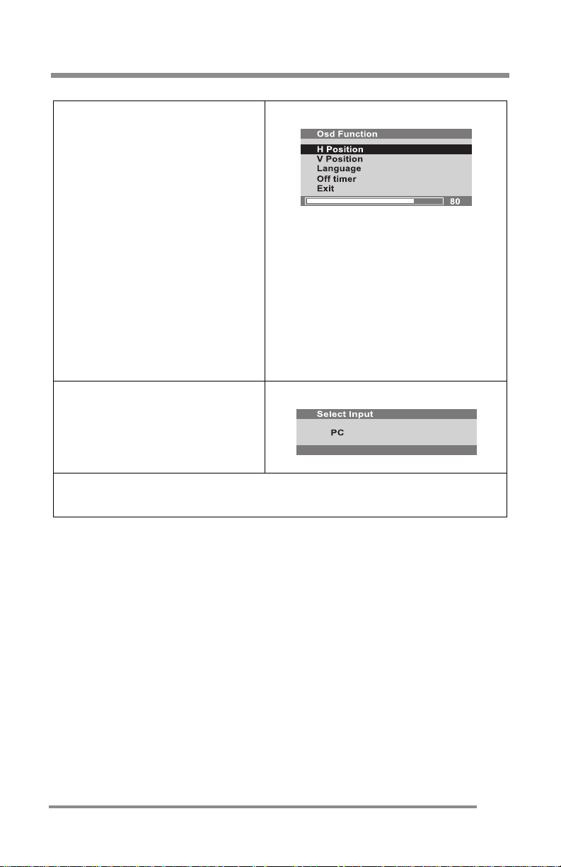
OSD FUNCTION (CT1503 only)
H Position
•Controls the OSD horizontal
position.
V Position
•Controls the OSD vertical
position.
Language
•Controls the language used for
the OSD.
Off Timer
•The OSD display time during
the absence of user control.
Exit
•Closes this sub-menu and
returns to the Main Me nu.
SELECT INPUT (CT1503)/
SETUP (CT1702)
•Displays current Input Signal.
•Allows change of the Input
Signal to the other options.
EXIT MENU
•Closes the Main Menu.
CT1503:
CT1503/CT1702:
33
Page 34
CONFIGURING & ADJUSTING the Display: TV/CATV (TUNER) Mode
CONFIGURING & ADJUSTING the Display: TV/CATV
(TUNER) Mode
Using the system’s On Screen Displays (OSD), you can adjust and refine
your Monitor’s image.
The following table describes the initial set-up steps and the other menus
available.
Remember,
when using the buttons on the front o f your Monitor:
• Pres s the MENU butt on to display the Main Menu.
▲ ▼
• Use the CHANNEL
buttons to scroll through the menu
items.
• Press the SELECT button to choose the desired menu item
to store the new value/parameter.
• Use the VOLUME
buttons to increase/decrease the
value/parameter.
Initial Set-Up & Adjustment of the Monitor
Select the Input Source Mode
1. Aft er all the connections are
made, turn ON the Moni to r and
other devices, as appropriate.
2. Select the Input Source mode by
using
either
the Remote Control:
•Pressing (re p eate d ly) the
SOURCE button
OR
The buttons on the front of the
Monitor by:
•Pressing th e SELE CT butto n
(repeated ly) to sc roll th rou gh
the variou s I np u t So urce
modes
OR
•From the Main Menu, choose
the SELECT INPUT (CT1503)/
SETUP option (CT1702).
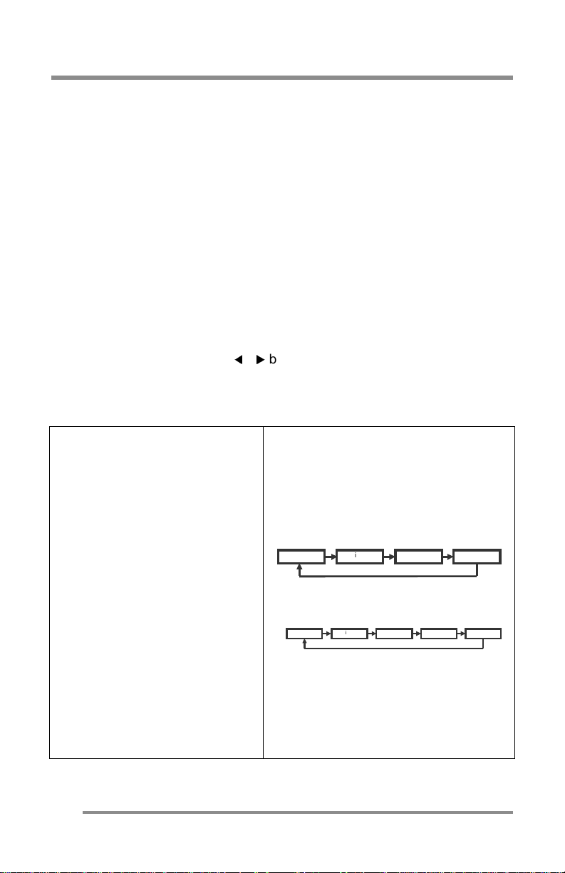
3. Select the TUNER mode.
CT1503 Input So ur ce Scroll Sequence:
CT1702 Input So ur ce Scroll Sequence:
and
Digital S-Video Tuner Analog
Digital Compos ite S-Video Tu ne r Analog
34
Page 35
CONFIGURING & ADJUSTING the Display: TV/CATV (TUNER) Mode
Adjust the Image Position & Clarity
4. If necessary,
•To adjust the VERTICAL position, see page 28.
•To adjust the HORIZONTAL position, see page 28.
•To adjust the CLARITY of the image, see page 29.
•To adjust the BRIGHTNESS of the image, see page 30.
•To adjust the CONTRAST of the image, see page 30.
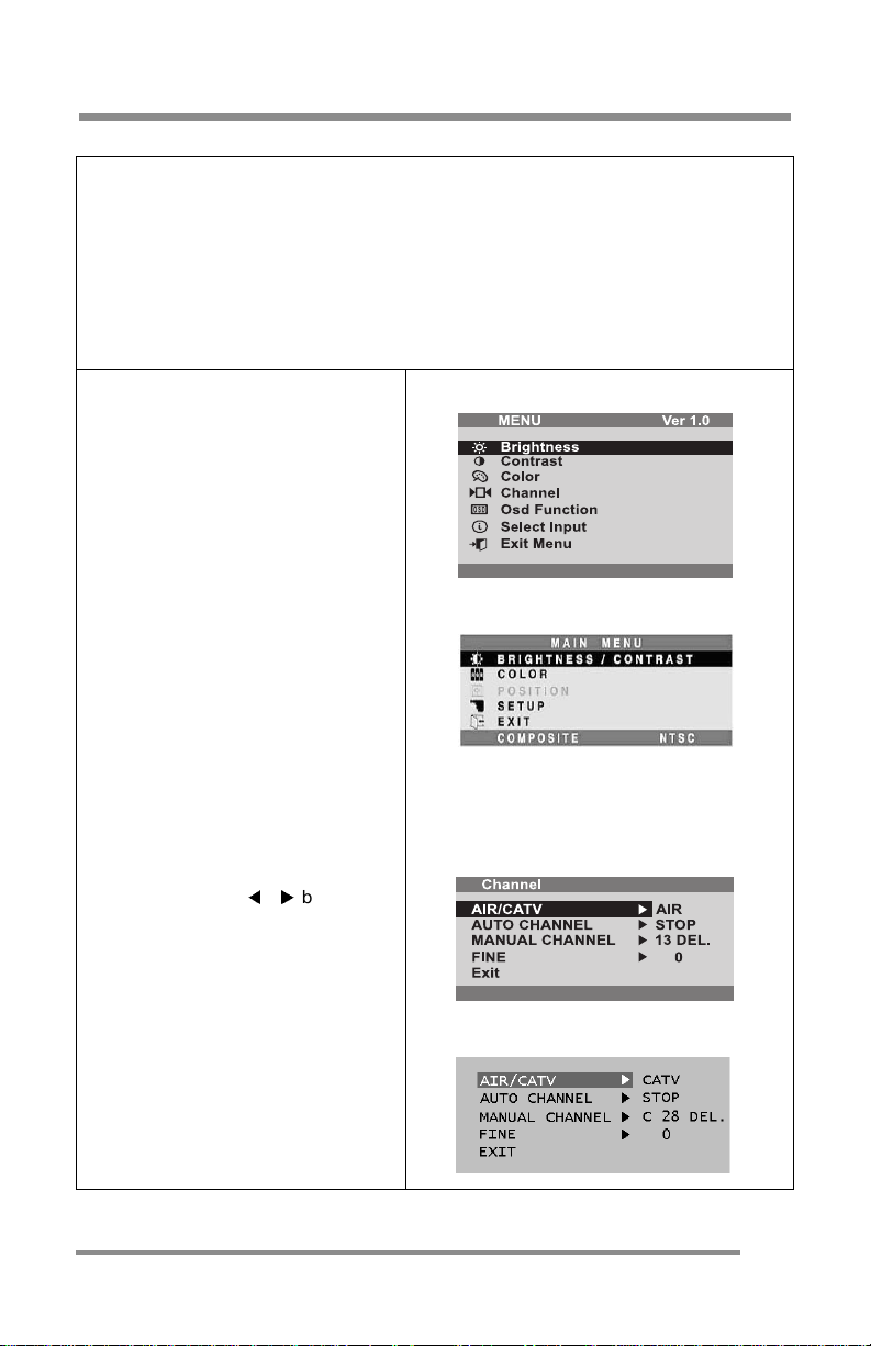
Select the Proper Antenna:
CT1503 Main Menu:
AIR or CATV
5. At the initial display, select the
antenna appropriate for your
system by:
•Pressing th e MEN U butto n to
display the Main Menu.
•Pressing the CHANNEL ▲ ▼
buttons (re pea te dly) to scro ll
to the CHANNEL option.
• Press the SELECT button to
select the item.
CT1702 Main Menu:
6. At the CHANNEL sub-menu:
•If the AIR/CATV item is not
highligh ted, us e CH AN N EL
▲ ▼ butto ns to s croll to it.
• Press the SELECT button to fully
highlight the AIR/CATV item.
•At the CHANNEL sub-menu, use
the VOLU ME
scroll through the antenna
options (Air or CATV).
•Press the SELECT button to
choose the appropriate
option.
buttons to
CT1503/CT1702 Channel Sub-Menu:
AIR Option:
CATV Option:
35
Page 36
CONFIGURING & ADJUSTING the Display: TV/CATV (TUNER) Mode
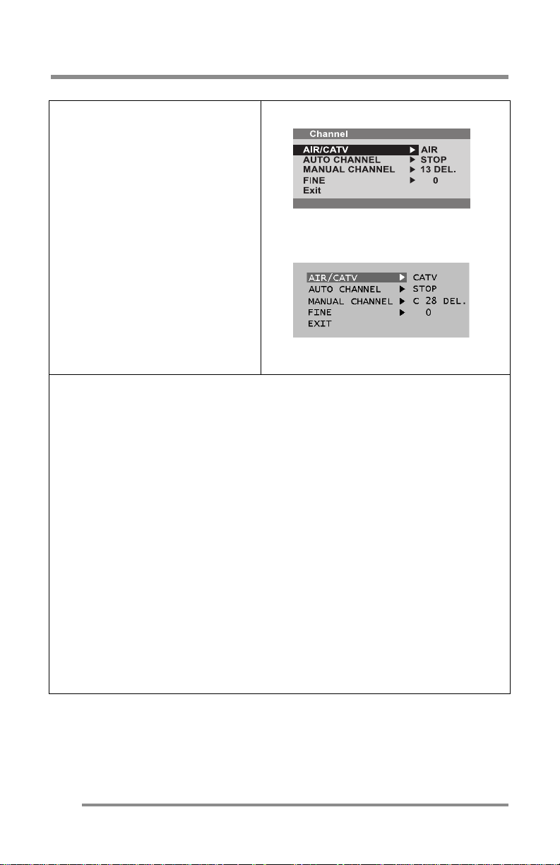
Automatically Search for
CT1503/CT1702 Channel Sub-Menu:
Channels
7. Whil e in this s ub-menu,
automatically search/add
chan nels from the cable s ystem
•Use the CHANNEL ▲ ▼
buttons, to s croll to the AUTO
CHANNEL item.
•Press the SELECT button to full y
highlight and view the options
for this item.
•The system will start
automatically searching and
adding ch anne ls.
8. If you do not want to automatically
search/add channels:
select this option.
to
:
CT1503/CT1702 Channel Sub-Menu:
do not
Other Sub-Menu Options:
Manually Add/Remove Channels:
9. Whil e in this s ub-menu:
•Use the CHANNEL ▲ ▼ buttons, to scroll to the MANUAL CHANNEL item.
•Press the SELECT button to fully highlight and view the options for this item.
•Use the CHANNEL ▲ ▼ buttons, to choose the ADD or DELETE option as
desired.
Refining the Video Image:
10. While in this sub-menu:
•Use the CHANNEL ▲ ▼ buttons, to scroll to the FINE item.
•Press the SELECT button to fully highlight and view the options for this item.
•Use the CHANNEL ▲ ▼ buttons, to increment the adjustment to make the
image as clear as possible.
EXIT the Sub-Menu
11. Usin g the CHANNEL ▲ ▼ buttons, scroll to th e EXIT item.
12. Press the SELECT button.
•This action returns you to the Main Menu.
36
Page 37
Explanation of Remaining Menu Items: TV/CATV (TUNER) & S-VIDEO Modes
Explanation of Remaining Menu Items: TV/CATV (TUNER)
& S-VIDEO Modes
The following table describes the other menus available.
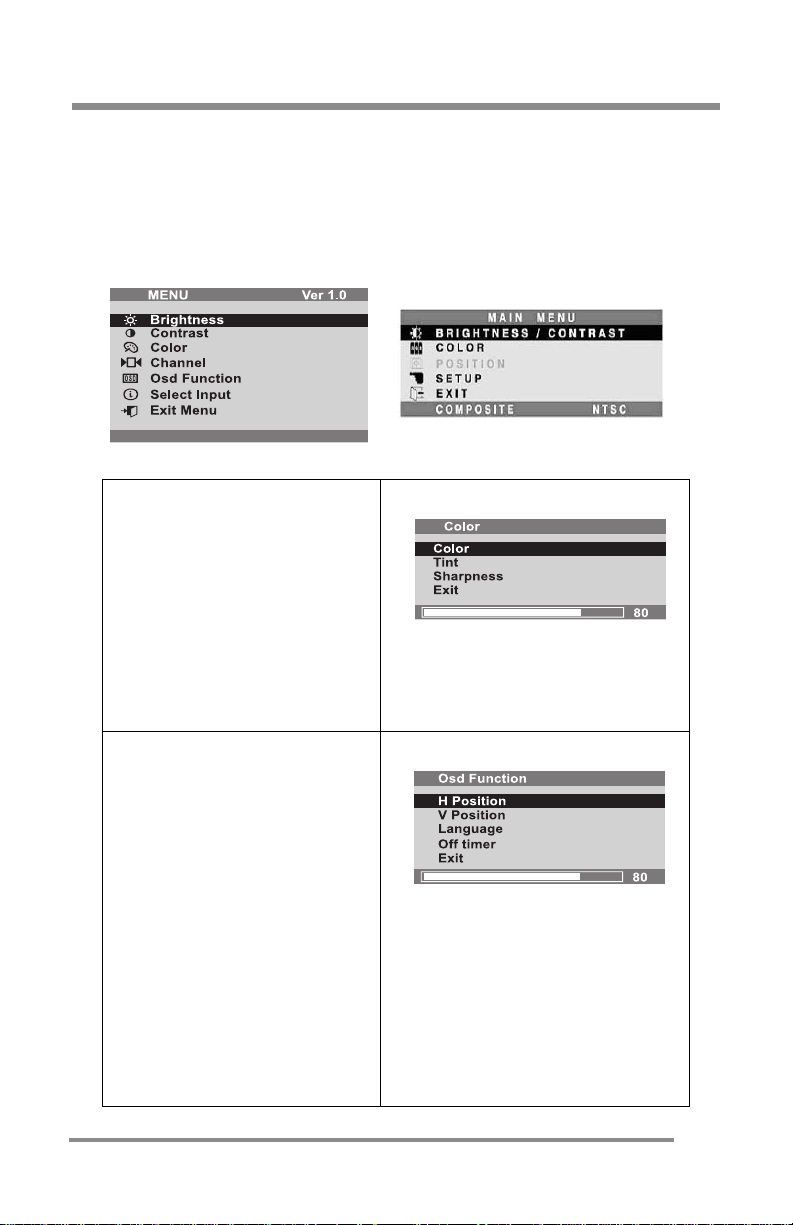
Figure 10: The Main Menus for the CT1503 and the CT1702, respectively
COLOR
Color
•Contro ls the thickness of the
color signal level.
Tint
•Controls the tone of the
color signal level.
Sharpness
•Controls the sharpness of
the signa l level .
OSD FUNCTION (CT1503 Only)
H Position
•Controls the OSD horizontal
position.
V Position
•Controls the OSD vertical
position.
Language
•Controls the language used
for the OSD.
Off Timer
•The OSD display time during
the absenc e of u s er control.
Exit
•Closes this sub-menu.
CT1503/CT1702 Color Sub-Menu:
CT1503 O S D Func tio n Sub -Menu:
37
Page 38
Explan a t ion of Rem aining Me n u I te m s: TV/CATV (TUNER) & S-VIDEO Mo des
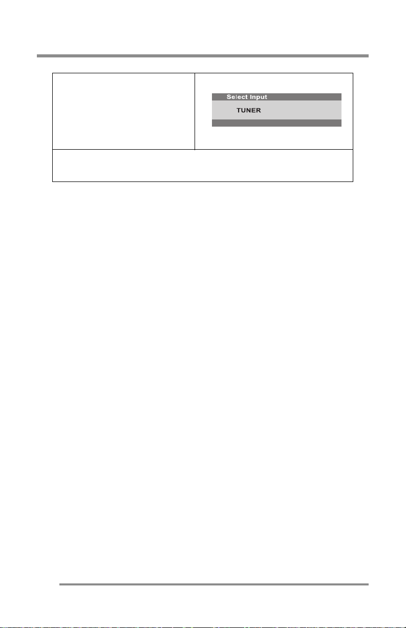
SELECT INPUT (CT1503)/
SETUP (CT1702)
•Displays current Input
Source.
•Allows change of the Input
Source to the other options.
EXIT
•Closes the Main Menu.
CT1503/CT1702 Sub-Menu:
38
Page 39
CONFIGURING & ADJUSTI NG th e Display: Externa l Devices (S-VIDEO ) Mode
CONFIGURING & ADJUSTING the Display:
External Devices (S-VIDEO) Mode
Using the system’s On Screen Displays (OSD), you can adjust and refine
your Monitor’s image.
The following table describes the initial set-up steps and the other menus
available.
Remember,
when using the buttons on the front o f your Monitor
• Pres s the MENU butt on to display the Main Menu.
▲ ▼
• Use the CHANNEL
buttons to scroll through the menu
items.
• Press the SELECT button to choose the desired menu item
to store the new value/parameter.
• Use the VOLUME
buttons to increase/decrease the
value/parameter.
Initial Set-Up & Adjustment of the Monitor
Select the Input Source Mode
1. After all the connections are
made, turn O N the Monitor and
other devices, as appropriate.
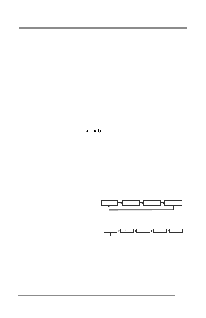
2. Select the Input Source mode by
using
either
the Remote Co ntrol:
•Pressing (repeatedly) the
SOURCE button
OR
The buttons on the front of th e
Monitor by:
•Pressing th e SELECT button
(repeatedly) to scroll through
the various Input Source
modes
OR
•From the Main Menu, choose
the SELECT INPUT (CT1503)/
SETUP option (CT1702).
3. Selec t the S-VIDEO mode.
CT1503 Input Sourc e Sc r o ll S equ e nc e:
CT1702 Input Sourc e Sc r o ll S equ e nc e:
:
and
Digital S-Video Tuner Analog
Digital Compos ite S-Video Tu ne r Analog
39
Page 40
CONFIGURING & ADJUSTING the Display: External Devices (S-VIDEO) Mode
Adjust the Image Position & Clarity
4. If necessary,
•To adjust the VERTICAL position, see page 28.
•To adjust the HORIZONTAL position, see page 28.
•To adjust the CLARITY of the image, see page 29.
•To adjust the BRIGHTNESS of the image, see page 30.
•To adjust the CONTRAST of the image, see page 30.
OTE
N
:
For an explanation of the remaining menu i tems,
please see the "Explanation of Remaining Menu
Items: TV/CATV (TUNER) & S-VIDEO Modes" section
on page 37.
40
Page 41
TROUBLESHOOTING: Resolution to Potential Problems
TROUBLESHOOTING: Resolution to Potential Problems
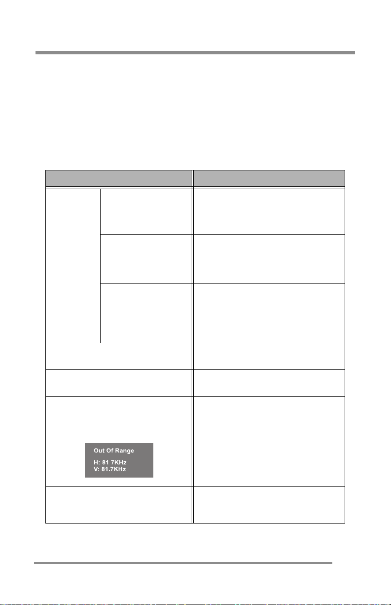
This section t r ie s to anticipate po t en t ial proble ms that you may enc ou nter
in the day-to-day use of your Monitor.
If, after trying the suggested solutions, your Monitor’s symptom remains the
same, contact your authorized service center or call Techni cal Support.
Troub les h oo tin g P ro ble m s
Problem Corrective Action
• Using the On Screen Display (OSD),
adjust the Brightness and Contrast to
maximum or reset them to the
default se t t i n gs .
•Check the power switch.
•Check if the AC Power Cord is
properly connected to the AC
Adapter.
•Check if the video signal cable is
properly connected at the back of
Monitor.
• Check if the power to computer
system is ON.
No Pictu re
LED Green
LED OFF
LED Amber
The display not clear.
The display is too light/dark.
The image is not centered.
“Out of Range” message
The picture is scrambled.
• Adjust the Frequency and Phase
settings using the OSD.
• Adjust the Brightness and Contrast
settings using the OSD.
• Adjust the Horizontal and Vertical
position settings using the OSD.
•Check the maximum resolution and
the frequency on the video port of
your Computer.
• Check the signal cable connection
between your Computer and
Monitor.
41
Page 42
TROUBLESHOOTING: Resolution to Potential Problems
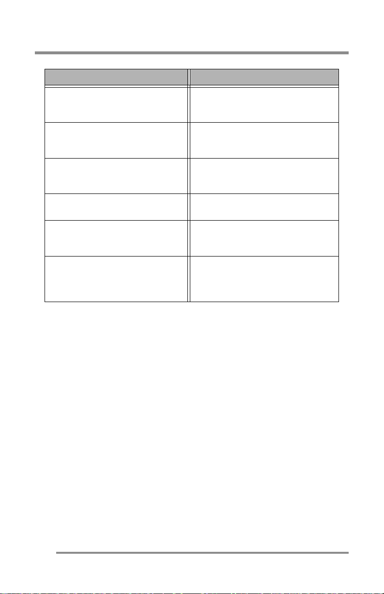
Problem Corrective Action
•Press the AUTO button, o n your
The picture is fuzzy.
The picture bounces or has wavy
oscillations.
Monitor, to automatically configure
your Monitor.
•Check the s ig na l ca b l e conne ction
between your Computer and
Monitor.
The picture appears to be ghosting.
The col o r on th e sc re e n is n o t uni f or m
The colors on the screen are
distorted with dark or shadowed
areas.
The Power Indicator is blinking an
amber color.
•Check the s ig na l ca b l e conne ction
between your Computer and
Monitor.
•Adjust the co lor se tt in gs using the
OSD color menu.
•Adjust the co lor se tt in gs using the
OSD color menu.
•The Moni tor is using it s power
management system. Check the
power management utility on your
Computer.
42
Page 43
APPENDIX: Warranty
APPENDIX: Warranty
END-USER WARRANTY TERMS AND CONDITIONS
Effecti ve 12/11/20 01
Cornea S ystems, Inc. (“Corn ea ”) wa rra n ts y o u r ne w Co rnea display (s)
against defects in material and workmanship during the warranty period
from the date of the original purchase of the new product within the
territory.
If a produc t proves t o be defective in mater i al or workmanship during the
warranty period, Cornea will, at its sole option, repair or replace the
prod u c t w ith a s im ilar product, provi ded the purchas e r ad h e res to ce rtain
return authorization procedures and guidelines.
For better service, Cornea strongly encourages you to register your
product by filling out the warranty registration card provided with your
produc t or regis t er onli n e.
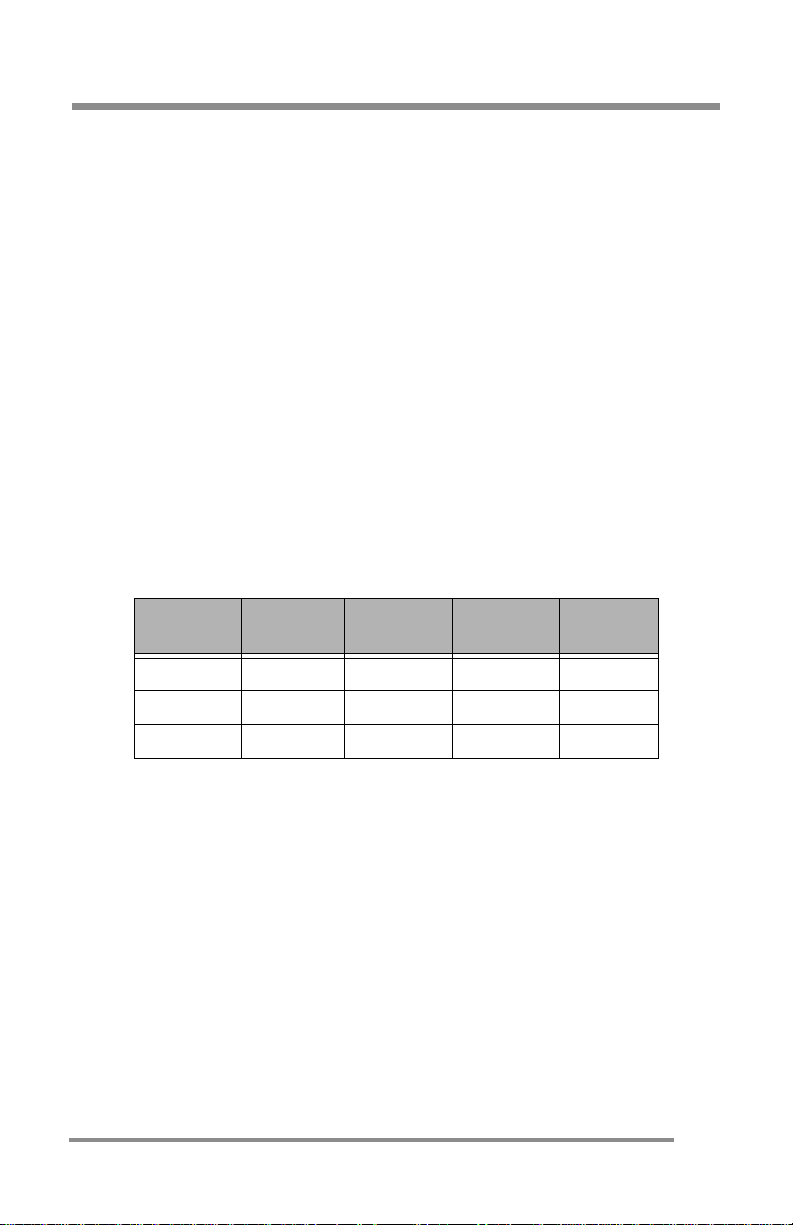
Warranty Period
Product
Type
TFT-LCD 3-Year 3-Year 3-Year 1st Year
LCD-TV 3-Year 3-Year 3-Year 1st Year
Plasma 1-Year 1-Year No No
Parts Labor Backlight
1st Year Advanced Swap Service
• If repairs are necessary, and you are entitled to service under
the te rm s and c onditions of the li m i ted war r an ty, a
replacement unit will be sent to you in exchange of your
defective f or repair during the first year p roduct warranty
period.
• With the ad va n ced swap service, s h ip pi ng is cov er ed both
directions. A return-shipping label will be included with the
replacem en t u n it .
• If an advanced swap is desired, the customer will be required
to submit a v al id credit card n u m ber, with th e ac cou n t in
good standin g , as collater al .
Advance
d Swap
43
Page 44

APPENDIX: Warranty
• Your credit card will be charged if the defective unit is not
received in 1 5 days afte r yo u receive the replacement.
This service will be provided exclusively by your Cornea Technical Support
Center and authorized agents. Your product will not be accepted for
repair unless you first contact Cornea Technical Support Center who will
provide instr uc tion s o n how to ret ur n your prod u c t for rep air . On ce the
product has been repaired, it will be returned free of charge to the
address you designated within the territory.
Date of Original Purchase
A copy of the customer’s original proof-of-purchase will be required to
establish the original date of pu rchase f or all warranty service. If a copy of
the origina l proof-of-purch ase is not available, the wa rranty period will be
considered to begin from the date of manufacture.
Territory
Warrant y geographic territ ory covers continental U SA and Canada.
Replacement of Produc t
Repla ceme nt prod uct or part s may inc lud e rema nufa ctur ed or re fur bish ed
parts or components. The replacement product is warranted for 60 days or
for the period remaining on the original warranty, whichever is greater.
Shipping
Replacement/repaired product will be shipped via UPS delivery, to any
point within the territory. Extra freight charges will apply for expedited
shipping, if such service is available.
Warranty Exclusion
• The limited warranty does not cover the repair of damages
occurring after you purchase the Monitor in shipping or in
storage or that caus ed b y dis ast er, a cciden t , misuse , abuse,
negligence, mishandling, improper packaging or shipping,
unauthorized repair or modification, or acts of God.
• This limited warranty does not cover repair of Monitor display
quality degradation resulting from failure of followin g the
manufacturer’s instruction with respect to proper handling,
operati on, in sta llati on, us age, se rvice and main tena nce of the
Monitor.
44
Page 45

APPENDIX: Warranty
• Cornea shall not be liable for any incidental or consequential
damages resulting from the use of this product.
• Do NOT open the Mon itor h ousing under a ny circumstances.
By opening the Monitor housing you will expose y ourself to
possib le electr ic al dangers and v oi d al l w arrantie s.
Before Contacting Us…
In many cases, your Monitor may not need repair. Before you contact us,
please consult the troubleshooting section in your user’s guide to see if you
can easily rem edy the problem yourself:
If this approach does not resolve your Cornea Monitor problem, please:
• Locate your proof of purchase date, indicated on your
receipt or i nvoice
• Get your product model and serial number (MPxxxxxxxx on the
back o f y our Monit or)
• Have th e de fe c t iv e product in f ront of you a n d call us.
Cornea Technical Support Service
During all th re e ye ar s of p ro du ct w a rr an t y , w e su pp ort you r basic
config u ration , set u p and troubleshoot in g questions, and whe n r equired,
we provid e you w i t h al l in structi on s on how to ret urn your prod u ct for
repair.
For support inquiries in the United States or Canada, please call:
1-800-681-6155
Monday through Friday
8 a.m. to 5 p.m. Pacific Time
Return Authorization Procedure
1. Contact Us
The Cornea Technical Support staff will help you identify if the unit
needs to be repaire d.
2. Fill out an RMA (RETURN MERCHANDISE AUTHORIZATION) Form
Once repair serv ice is requ ir ed, yo u’ll be instruct e d t o fill o ut an RM A
form (available online). You will be requested to provide product
model na m e an d se ri al numb er (l oc at ed on the ba ck of y our Mon i to r),
the origina l pr oof-of-purchase, your name and contact informa tion, a
descriptio n of th e prob lem & your credit card (VIS A , Mast erC ar d, o r
45
Page 46
APPENDIX: Warranty
American Express) information, if first year advanced swap is
applicable.
3. Acquir e an RMA Numbe r
After we receive your RMA request, Cornea technica l support staff wil l
contact you within 48 hours and assign you an RMA number. For
advanc e d sw ap service, a replace ment uni t wi ll be sent to you.
4. Return the Unit for Repai r /Re placement
Please send your original unit back to us in the original unit box.
Damage due to improper or inadequat e packing will be charged to
you as an out-of-warranty cost. For advanced swap service, please
use th e pr ovided mailing label. A designated cour ier will pick up the
returned. T he original unit must be properly packaged in the sam e
manner as the r eplacement unit, utilizing the pack ing materials
provided.
5. Receive a Replacement/Repaired Unit
Once the unit is repaired, we will ship back to you free of charge. If the
unit is not repairable, we will send you a replacement instead.
46
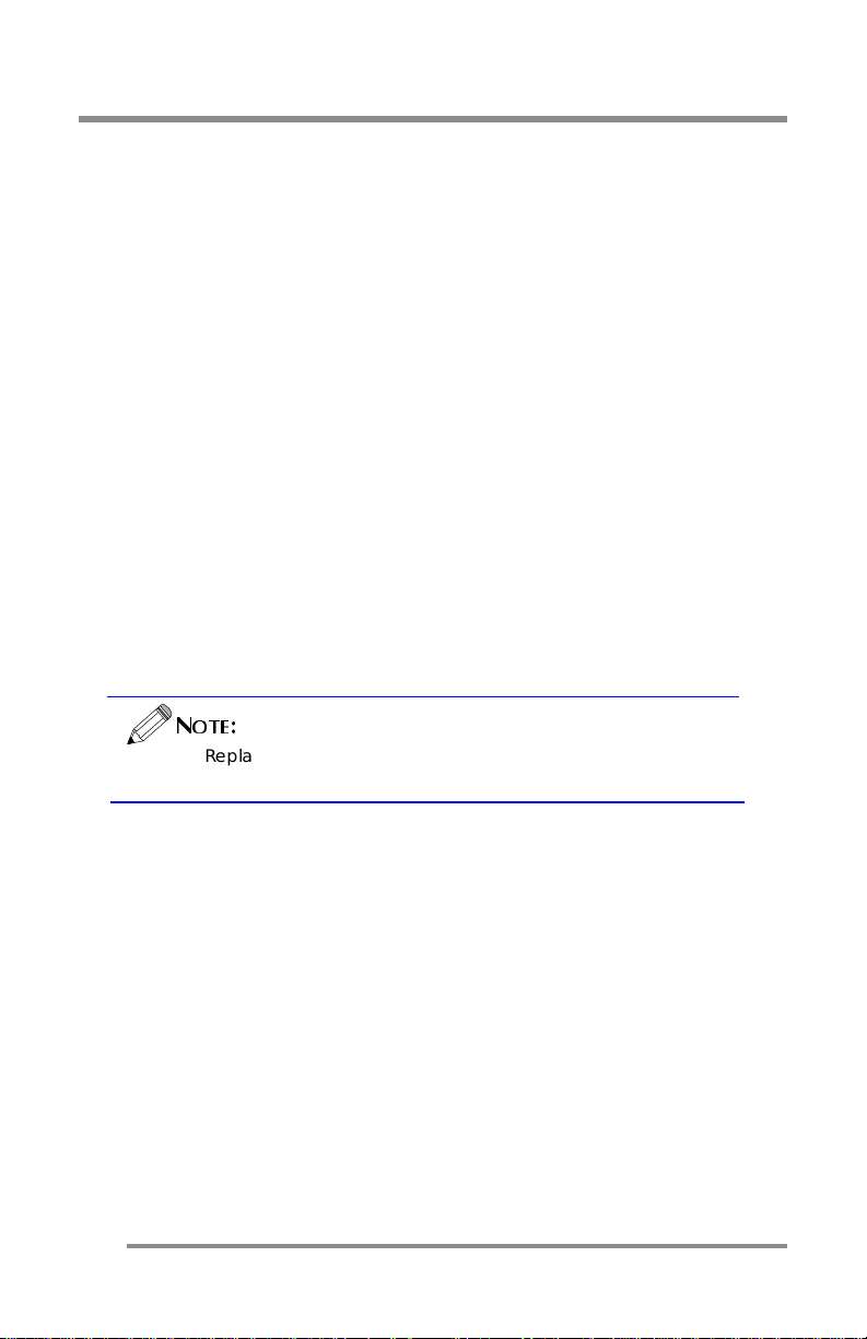
OTE
N
:
Replacemen t prog ram is sub jec t to terminat io n at
any time w it ho ut advance not ice.
Page 47
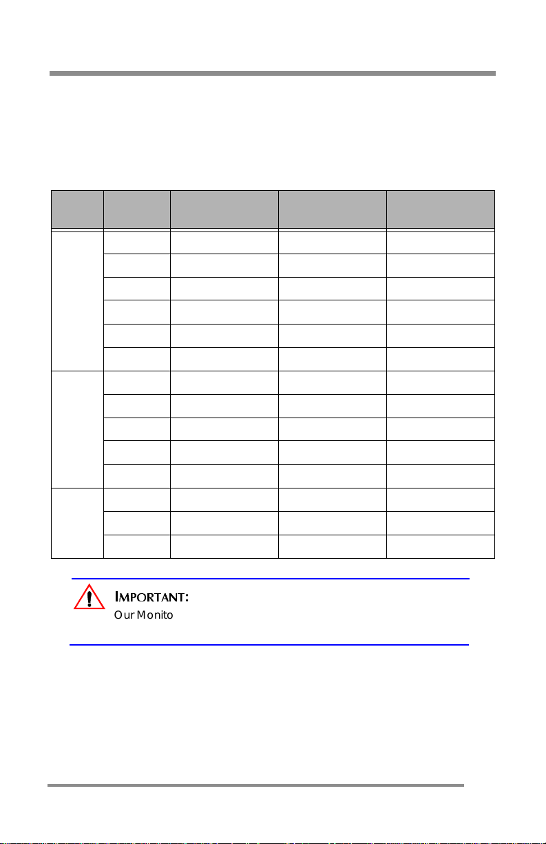
APPENDIX: CT1503 Analog Display Modes (Analog )
APPENDIX: CT1503 Analog Display Modes (Analog)
For the display modes listed below, the screen image has been optimized
during production.
Preset Timing Modes ( Analog)
Mode
VGA
SVGA
XGA
Display
Mode
640 x 350 31.5KHz 70Hz IBM®
720 x 400 31.5KHz 70Hz IBM®
640 x 480 31.5KHz 60Hz Industry Standard
640 x 480 37.9KHz 72Hz VESA Standard
640 x 480 37.5KHz 75Hz VESA Standard
640 x 480 43.3KHz 85Hz VESA Standard
800 x 600 35.2KHz 56Hz VESA Guidelines
800 x 600 37.9KHz 60Hz VESA Guidelines
800 x 600 48.0KHz 72Hz VESA Standard
800 x 600 46.9KHz 75Hz VESA Standard
800 x 600 53.7KHz 85Hz VESA Standard
1024 x 768 48.4KHz 60Hz VESA Guidelines
1024 x 768 56.5KHz 70Hz VESA Standard
1024 x 768 60.0KHz 75Hz VESA Standard
MPORTANT
I
Our Monitor is not supp orte d outs id e of th e disp lay m ode s
liste d above.
Horizontal
Frequency (KHz)
:
Vertical
Frequency (Hz)
Standard Type
47
Page 48
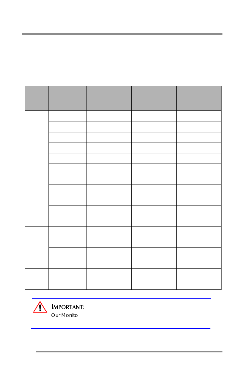
APPENDIX: CT1702 Display Mode s (An alog)
APPENDIX: CT1702 Display Modes (Analog)
For the display modes listed below, the screen image has been optimized
during production.
Preset Timing M odes (Analog)
Mode
VGA
SVGA
XGA
Display
Mode
640 x 350 31.5KHz 70Hz IBM®
720 x 400 31.5KHz 70Hz IBM®
640 x 480 31.5KHz 60Hz Industry Standard
640 x 480 37.9KHz 72Hz VESA Standard
640 x 480 37.5KHz 75Hz VESA Standard
640 x 480 43.3KHz 85Hz VESA Standard
800 x 600 35.2KHz 56Hz VESA Guidelines
800 x 600 37.9KHz 60Hz VESA Guidelines
800 x 600 48.0KHz 72Hz VESA Standard
800 x 600 46.9KHz 75Hz VESA Standard
800 x 600 53.7KHz 85Hz VESA Standard
1024 x 768 48.4KHz 60Hz VESA Guidelines
1024 x 768 56.5KHz 70Hz VESA Standard
1024 x 768 60.0KHz 75Hz VESA Standard
1024 x 768 68.7KHz 85Hz VESA Standard
Horizontal
Frequency
(KHz)
Vertical
Frequency
(Hz)
Standard
Type
48
SXGA
1280 x 1024 64.0KHz 60Hz VESA Standard
1280 x 1024 80.0KHz 75Hz VESA Standard
MPORTANT
I
Our Monitor is not supp orte d outs id e of th e disp lay m ode s
liste d above.
:
Page 49
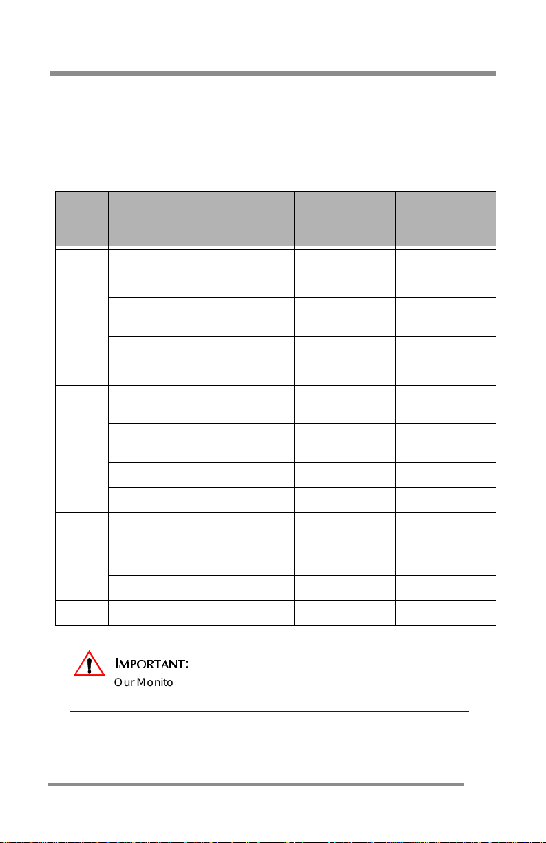
APPENDIX: CT1703 Display Mode s (Digital)
APPENDIX: CT1703 Display Modes (Digital)
For the display modes listed below, the screen image has been optimized
during production.
Preset Timing Mo des (Digital)
Mode
VGA
SVGA
XGA
Display
Mode
640 x 350 31.5KHz 70Hz IBM®
720 x 400 31.5KHz 70Hz IBM®
640 x 480 31.5KHz 60Hz
640 x 480 37.9KHz 72Hz VESA Standard
640 x 480 37.5KHz 75Hz VESA Standard
800 x 600 35.2KHz 56Hz
800 x 600 37.9KHz 60Hz
800 x 600 48.0KHz 72Hz VESA Standard
800 x 600 46.9KHz 75Hz VESA Standard
1024 x 7 68 48.4K H z 60Hz
1024 x 768 56. 5K Hz 70Hz VES A Sta nd a rd
1024 x 768 60. 0K Hz 75Hz VES A Sta nd a rd
Horizontal
Frequency
(KHz)
Vertical
Frequency
(Hz)
Standard
Type
Industry
Standard
VESA
Guidelines
VESA
Guidelines
VESA
Guidelines
SXGA
1280 x 10 24 64 .0K H z 60Hz VES A Sta nd a r d
MPORTANT
I
Our Monitor is not supp orte d outs id e of th e disp lay m ode s
liste d above.
:
49
Page 50
APPENDIX: Regulatory Compliance
APPENDIX: Regulatory Compliance
Canadian Department of Communications Compliance Statement
DOC: This Class B digital apparatus meets all requirements of the Canadian
Interference-Caus ing Equi pmen t Regulation s.
C-UL: Bears the C-UL Mark and is in compliance with Canadian Safety Regulations according to
C.S.A. C22.2 No. 950.
FCC Information
1. Use the attached specified cables with the CT1503/CT1703 color monitor so as not to interfere
with radio and television reception.
(1) Please use the supplied power cable or equivalent to ensure FCC compliance.
(2) Please use the supplied AC Adapter.
(3) Please use the supplied shielded video signal cable.
(4) Please use the supplied DVI-D to DVI-D cable.
(5) Please use the supplied USB cable.
Use of other cables and adapters may cause interference with radio and television
reception.
2. This equipment has been tested and found to comply with the limits for a Class B digital
device, pursuant to part 15 of the FCC Rules. These limits are designed to provide reasonable
protection against harmful interfer ence in a residen tial installat io n. This equipment gene rates,
uses, and can radiate radio frequency energy, and, if not installed and used in accordance
with the instructions, may cause harmful interference to radio communications.
However, there is no guarantee that interference will not occur in a particular installation. If
this equipment does cause harmful interfere nce to radio or television reception, which can
be determined by turning the equipment off and on, the user is encouraged to try to correct
the interference by one or more of the following measures:
• Reorient or relocate the receiving antenna.
• Increase the separation between the equipment and receiver.
• C onnect the equ ipment into an o utlet on a circuit dif ferent from that to which the receiver
is connected.
• Consult your dealer or an experienced radio/TV technician for help.
If necessary, the user should contact the dealer or an experienced radio/television technician
for additional suggestions. The user may find the following booklet, prepared by the Federal
Communications Com mission, helpful: “How to Identify and Resolve Radio-TV Interference
Problems”. This booklet is available from the U.S. Government Printing Office, Washington, D.C.,
20402, Stock No. 004-000-00345-4.
50
 Loading...