

Page 1

INSTALLATION
AND
MAINTENANCE
TROUBLESHOOTING
Content:
1. Precautions before Performing Inspection or Repair
2. Conrmation
3. Flashing LED of Indoor/Outdoor Unit and Primary Judgement
4. How to Check Simply the Main Part
5. Troubleshooting for Normal Malfunction
Page 2
1. Troubleshooting
1.1 Precautions before Performing Inspection or Repair
Be cautious during installation and maintenance. Do operation following the regulations to avoid electric shock and casualty or even death
due to drop from high attitude.
* Static maintenance is the maintenance during de-energization of the air conditioner.
For static maintenance, make sure that the unit is de-energized and the plug is disconnected.
*dynamic maintenance is the maintenance during energization of the unit.
Before dynamic maintenance, check the electricity and ensure that there is ground wire on the site. Check if there is electricity on the housing and connection copper pipe of the air conditioner with voltage tester. After ensure insulation place and the safety, the maintenance can
be performed.
Take sufcient care to avoid directly touching any of the circuit parts without rst turning off the power.
At times such as when the circuit board is to be replaced, place the circuit board assembly in a vertical position.
Normally,diagnose troubles according to the trouble diagnosis procedure as described below.(Refer to the check points in servicing written
on the wiring diagrams attached to the indoor/outdoor units.)
No. Troubleshooting procedure
1 Conrmation
2 Judgement by Flashing LED of Indoor/Outdoor Unit
3 How to Check Simply the Main Part
NOTE:
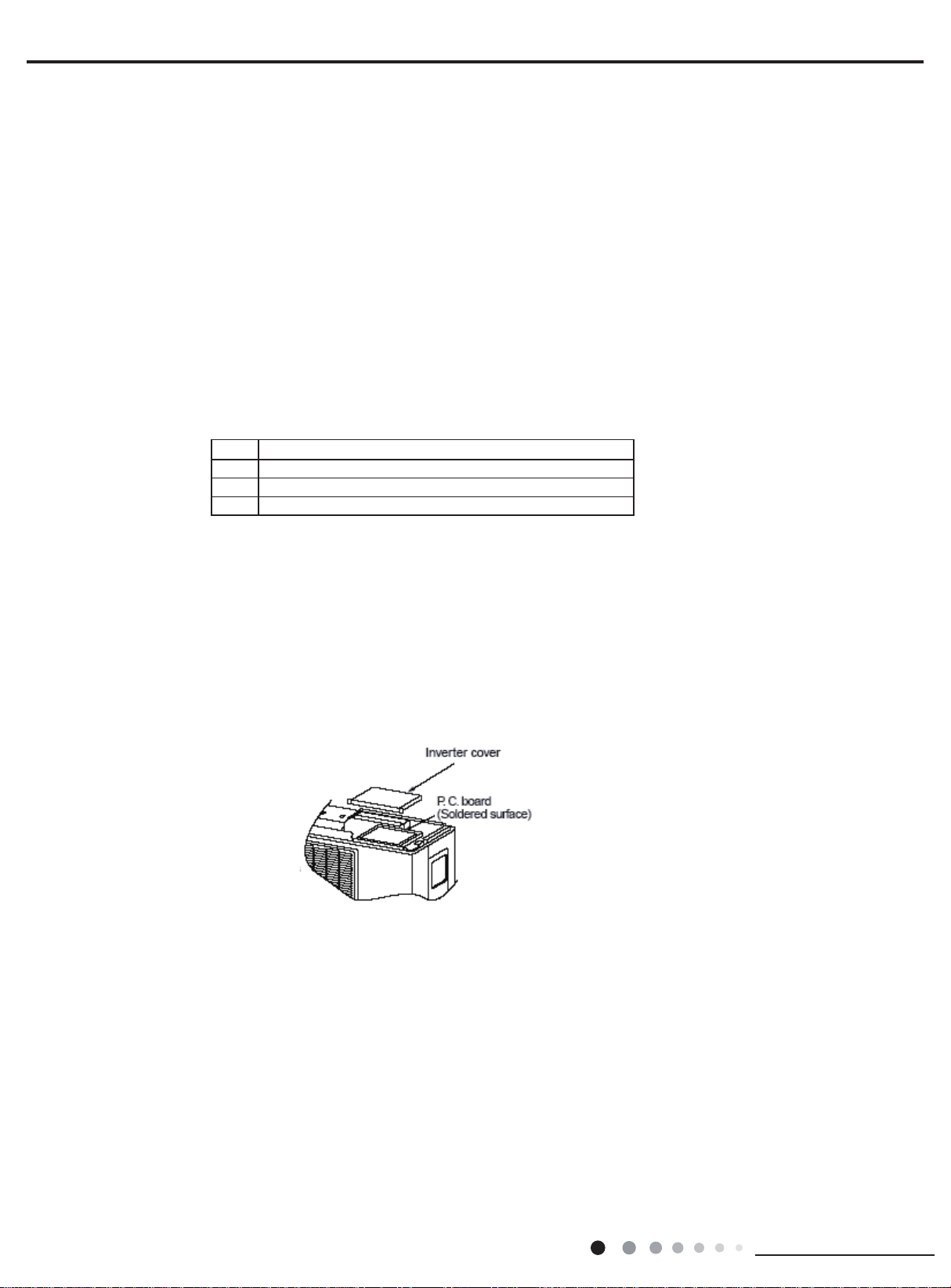
A large-capacity electrolytic capacitor is used in the outdoor unit controller(inverter).Therefore,if the power supply is turned
off,charge(charging voltage DC280V to 380V)remains and discharging takes a lot of time. After turning off the power source,if touching the
charging section before discharging, an electrical shock may be caused. Discharge the electrolytic capacitor completely by using soldering
iron,etc.
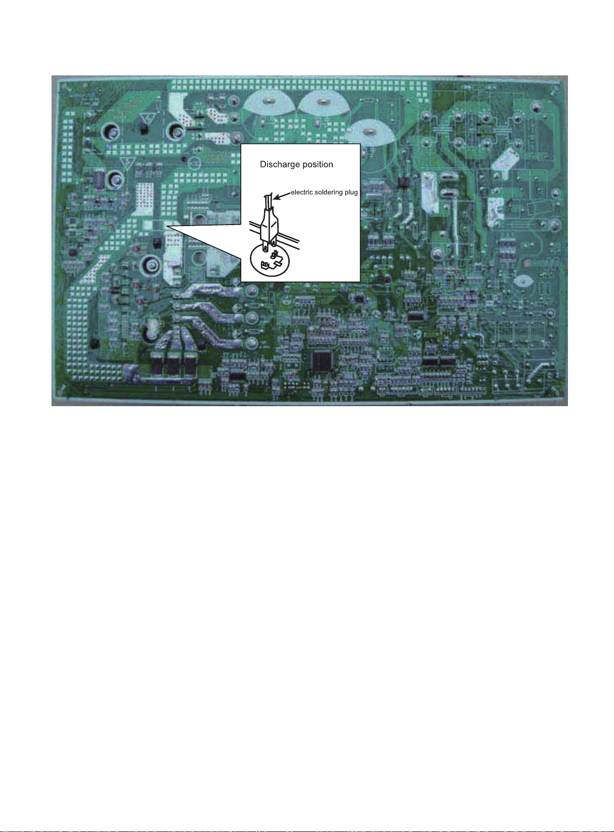
Discharging method
(1)remove the inverter cover(Outoor Unit)
(2)As shown below,connect the discharge rescharge resistance(approx.100Ω,20W) or plug of the soldering iron to voltage between + -
terminals of the electrolytic capacitor (test 3*D* and *E* point) on PC Board for 30s ,and then perform discharging
2
Installation and Maintenance
Page 3
2. Conrmation
(1)Conrmation of Power Supply
Conrm that the power breaker operates(ON) normally;
(2)Conrmation of Power Voltage
Conrm that power voltage is AC 208-230 ±10%. If power voltage is not in this range, the unit may not operate normally.
3. Flashing LED of Indoor/Outdoor Unit and Primary Judgement
3
Page 4
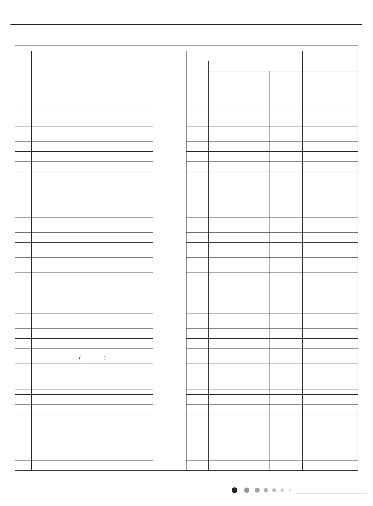
(1)Models:09/12K:
Malfunction and Status Display Table
15 times
Display of Malfunction of Indoor Unit
No. Malfunction Name
1 Malfunction of Circuit for zero cross detection U8
2 Malfunction protection for jumper cap C5
3 No feedback from indoor motor H6
Indoor ambient temp sensor has open or short
4
Indoor evaporator temp sensor has open or
5
Liquid valve temp sensor has open or short
6
7
8 Module temp sensor has open or short circuit P7
9
10
11
12
13
14
15
16 Demagnetization protection of compressor HE
17 Malfunction of voltage drop of DC bus bar U3
18 Module temperature protection P8
19
20 Malfunction of charging for capacitor PU
21 High pressure protection for the system E1
22
23
24
25 Overspeed (for commercial air conditioner)
26 Malfunction of
27
28
29
30
31 Thermal overload protection for compressor H3
32 Non-match between indoor and outdoor units LP
33 Malfunction of memory chip
Gas valve temp sensor has open or short
Outdoor ambient temp sensor has open or
Outdoor inlet pipe temp sensor of condenser
has open or circuit (for commercial use)
Outdoor middle pipe temp sensor of condenser
Outdoor outlet pipe of condenser has open or
Outdoor discharge temp sensor has open or
Communication malfunction of indoor and
Malfunction of circuit for detecting phase
Lack of refrigerant or block protection for the
Reset of drive module (for commercial air
AC contactor protection (for commercial air
Temperature drift protection(for commercial air
Sensor connection protection (for commercial
Communication malfunction for drive board(for
has open or short circuit
short circuit (for commercial use)
current of compressor
system (not applicable to residential air
Low pressure protection for the system
Lock of compressor (for commercial air
commercial air conditioner)
circuit
short circuit
circuit
circuit
short circuit
short circuit
outdoor units
conditioner)
reserved
conditioner)
conditioner)
conditioner)
conditioner)
air conditioner)
Malfunction
Type
Malfunction
of
hardware
Display
Nixie
Tube
Operation
F1
F2
b5
b7
F3
A5
F4
A7
F5
E6
U1
F0
E3
LE / / /
P0 / / /
/ / /
LF
/ / /
PF
P9 / / /
PE / /
Pd / / /
P6
EE
Status of LED Lamp
LED
Lamp
for
Blinks
for 17
times
Blinks
for 15
times
Blinks
for 11
times
Blinks
for 6
times
Blinks
once
Blinks
for 3
times
Blinks
for 16
times
LED Lamp
for
Cooling
Blinks
once
Blinks
twice
Blinks for
19 times
Blinks for
22 times
Blinks for
3 times
Blinks for
4 times
Blinks for
5 times
Blinks for
10 times
LED Lamp
Heating
Blinks for
18times
Blinks for
12 times
Blinks for
14 times
Blinks for
20 times
Blinks for
19 times
Blinks for
17 times
Blinks for
3 times
Blinks for
Malfunction of
Outdoor Unit
Status of LED
Lamp
for
Yellow
LED
Lamp
Blinks for
10 times
Blinks for
8 times
Blinks for
16 times
Red
LED
Lamp
Blinks
for 6
times
Blinks
for 5
times
Blinks
for 7
times
Blinks
for 9
times
4
Installation and Maintenance
Page 5
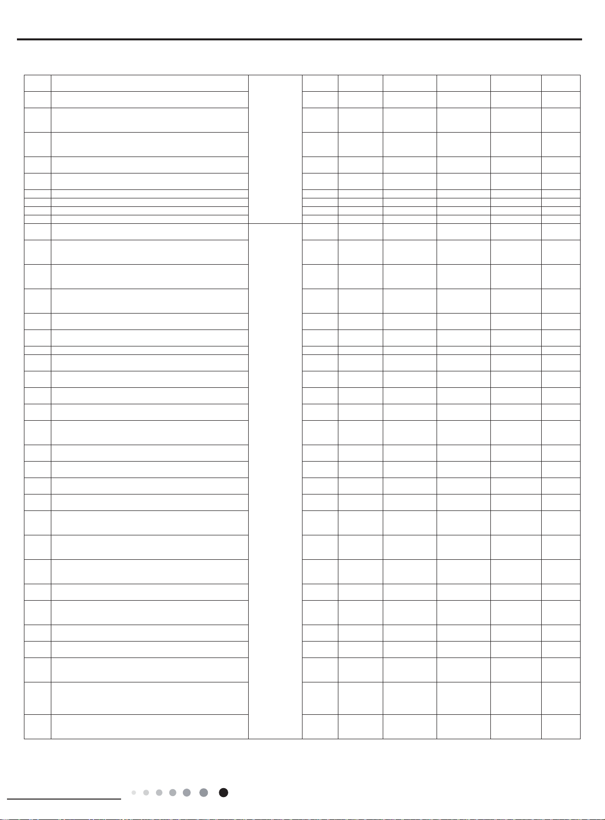
34
Wrong connection of communication wire or
times
35
36
37 Mode conflict E7
38 Refrigerant reclaiming mode Fo
39 Oil return under defrosting or heating H1
40 Nominal cooling or heating (capacity test code) P1 / / /
41 Max. cooling or heating (capacity test code) P2 / / /
42 Middle cooling or heating(capacity test code) P3 / / /
43 Min. cooling or heating(capacity test code) P0 / /
44 Failure of startup of compressor Lc
45
46 Overload protection E8
47 Overcurrent protection for the complete unit E5
48 Overcurrent protection for the complete unit P5
49 Desynchronizing of compressor H7
50 Lack/reverse phase protection of Ld / / /
51 Module current protection (IPM protection) H5
52 Overlow voltage protection for DC bus bar PL
53 Overhigh voltage protection for DC bus bar PH
54 PFC protection HC
55 Overhigh power protection (not for outdoor L9
56 Abnormal reversing of 4-way valve U7
57
58
59
60 Frequency limit/decrease for freeze protection FH
61 Frequency limit/decrease for overload F6
62
63 Oil return in cooling F7
64 Cold air prevention E9
65 Freeze protection E2
66 Reading malfunction of EEPROM
67 Reaching temperature for turning on the unit
68 Frequency limit (power)
69 Malfunction of outdoor fan
malfunction of expansion valve (free match)
Malfunction of current detection for the
Wrong connection of communication wire or
status of detecting malfunction of expansion
High discharge temperature protection of
Frequency limit/decrease for current protection
Frequency limit/decrease for current protection
of the module (phase current)
Frequency limit/decrease for high discharge
Frequency limit/decrease for module
complete unit
valve (free match)
compressor
of the complete unit
temperature
temperature protection
Display is
controlled
by remote
control
dn / / /
U5
dd / / /
Blinks
for 7
times
Blinks
once
E4
F8
En / / /
F9
EU
Blinks
for 4
times
Blinks
for 8
times
Blinks
for 5
times
Blinks
for 20
times
Blinks
for 9
times
Blinks
twice
Blinks for
13 imes
Blinks
once
Blinks for
11 times
Blinks for
20 times
Blinks for
8 times
Blinks for
9 times
Blinks
twice
Blinks for
6 times
Blinks for
6 times
Blinks for
7 times
Blinks
once
Blinks for
11 times
Blinks for
15 times
Blinks for
7 times
Blinks for
5 times
Blinks for
21 times
Blinks for
6 times
Blinks
twice
Blinks for
6 times
Blinks
twice
Blinks for
7 times
Blinks for
6 times
Blinks for
5 times
Blinks for
4 times
Blinks for
12 times
Blinks for
13 times
Blinks for
14 times
Blinks for
9 times
Blinks
once
Blinks
twice
Blinks for
3 times
Blinks for
11 times
Blinks
for 4
times
Blinks
for 3
times
Blinks
for 11
times
Blinks
for 8
times
Blinks
13time
Blinks
for 14
for
s
Installation and Maintenance
5
Page 6
If malfunction occurs,corresponding code will display and the unit will resume normal until protection or
malfunction disappears.
Compressor stars (normal)Yellow indicator blinks for once
Yellow indicator
blinks for twice
Yellow indicator blinks for 3 times
Yellow indicator blinks for 4 times
Yellow indicator blinks for 5 times
Yellow indicator blinks for 6 times
Yellow indicator blinks for 7 times
Yellow indicator blinks for 8 times
Defrosting
Anti-freezing protection (normal
IPM protection
Overcurrent protection
Overload protection
Exhaust protection
Overlod protection of compresoor
(normal display of indoor unit)
display of indoor unit)
Indicator display
of outdoor unit
Red indicator blinks for once
Red indicator blinks for twice
Red indicator blinksfor 3 times
Cooling (dehumidify) or heating current
dropped frequency current.
Exhaust temp. dropped frequency temp.
Tube
temp. dropped frequency temp.
Red indicator blinks for 4 times
Red indicator blinks for 5 times
Red indicator for 6 times
Red indicator blinks for 7 times
Red indicator blinks for 8 times
Green indicator does not blink
T
tube-in
dropped frequency temp.
Outdoor condenser temp. sensor mal.
Outdoor ambient temp. sensor mal.
Outdoor exhaust temp. sensor mal.
Starting at temp. does not reach
Communication is abnormal
6
Installation and Maintenance
Page 7
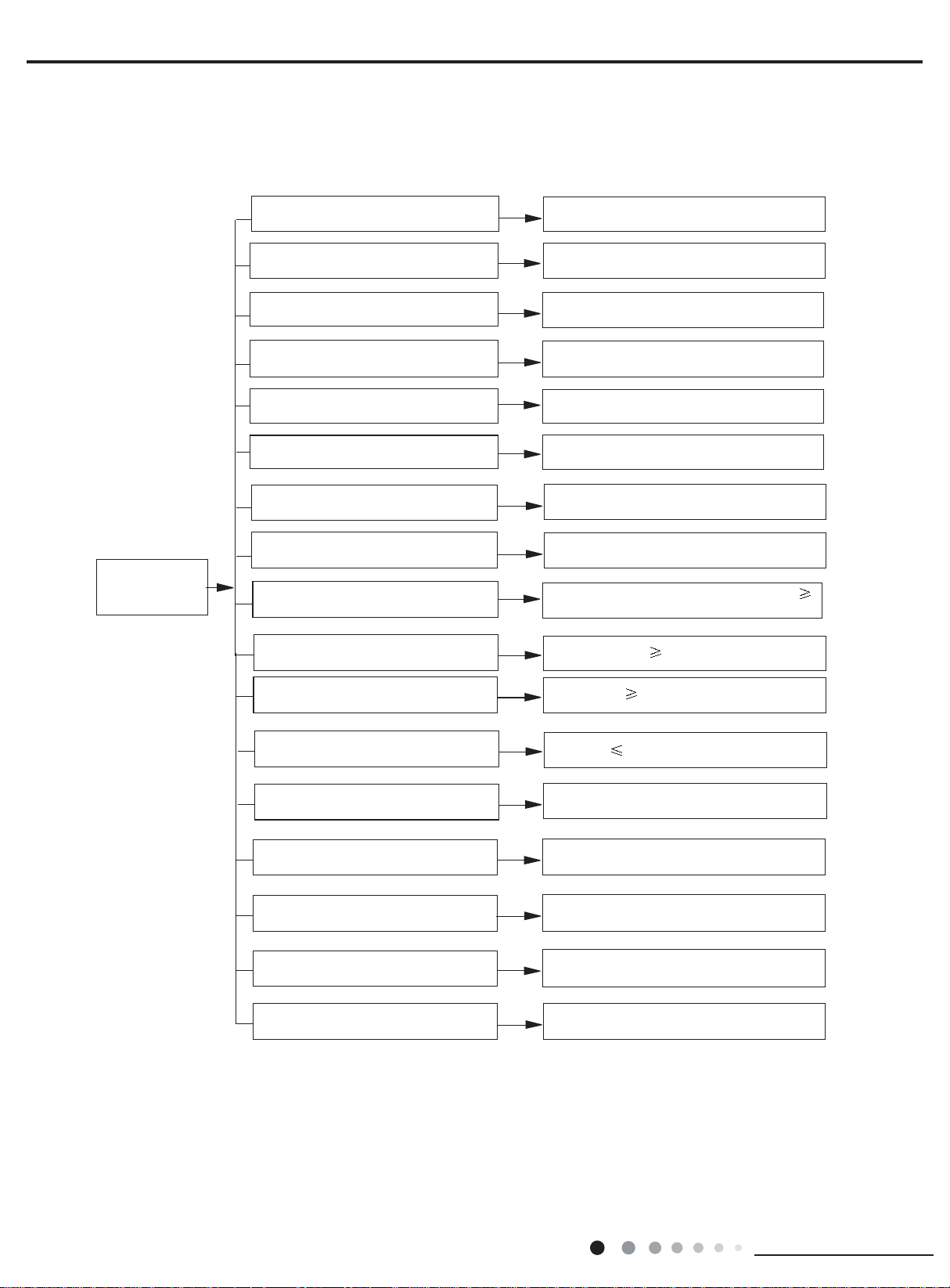
A
nalysis or processing of some of the malfunction display:
1. Compressor discharge protection
operation;
malfunction of compressor; malfunction of protection relay; malfunction of discharge sensor; outdoor temperature too
high.
Processing method: refer to the malfunction analysis in the above section
2. Low voltage overcurrent protection
Possible reason: Sudden drop of supply voltage.
3. Communic ation malfun ction
Processing method: Check if communic ation signal cable is connected reliably
4. Sensor open or short circuit
Processing
f
lead wire is found.
5. Compressor over load protection
Possible
compresso
Processing
the
6. System malfun ction
Overload
e
temperature of indoor heat exchanger when heating) is too high, protection will beactivated.
Please refer to the malfunction analysis in the previous section for handling method
7. IPM module protection
Processing
power
the malfunction still exists,replace the module.
(2)Models:18/24K:
method: Check whethers ensor is normal, connected with the corre sponding position on the controller and if damage o
reasons: insufficient or too much refrigrant; blockage of capillary an dincrease of su ction temp.; improper running of
r, burning in or stuck of bearing, damage of discharge valve; malfunction of protector.
method: adjust refrige rant amount; replace the capillary; replace the compressor; use univers al meter to check if
.
.
.
protection.When tube temperature(Check the temperature of outdoor heat exchanger when cooling and check th
method:Once the module malfunction happens,if it persists for a long time and can not be self-canceled, cut off the
and turn off the unit,and then re-energize the unit again after about 10 min.After repeating the procedure for sever times, if
.
Installation and Maintenance
7
Page 8
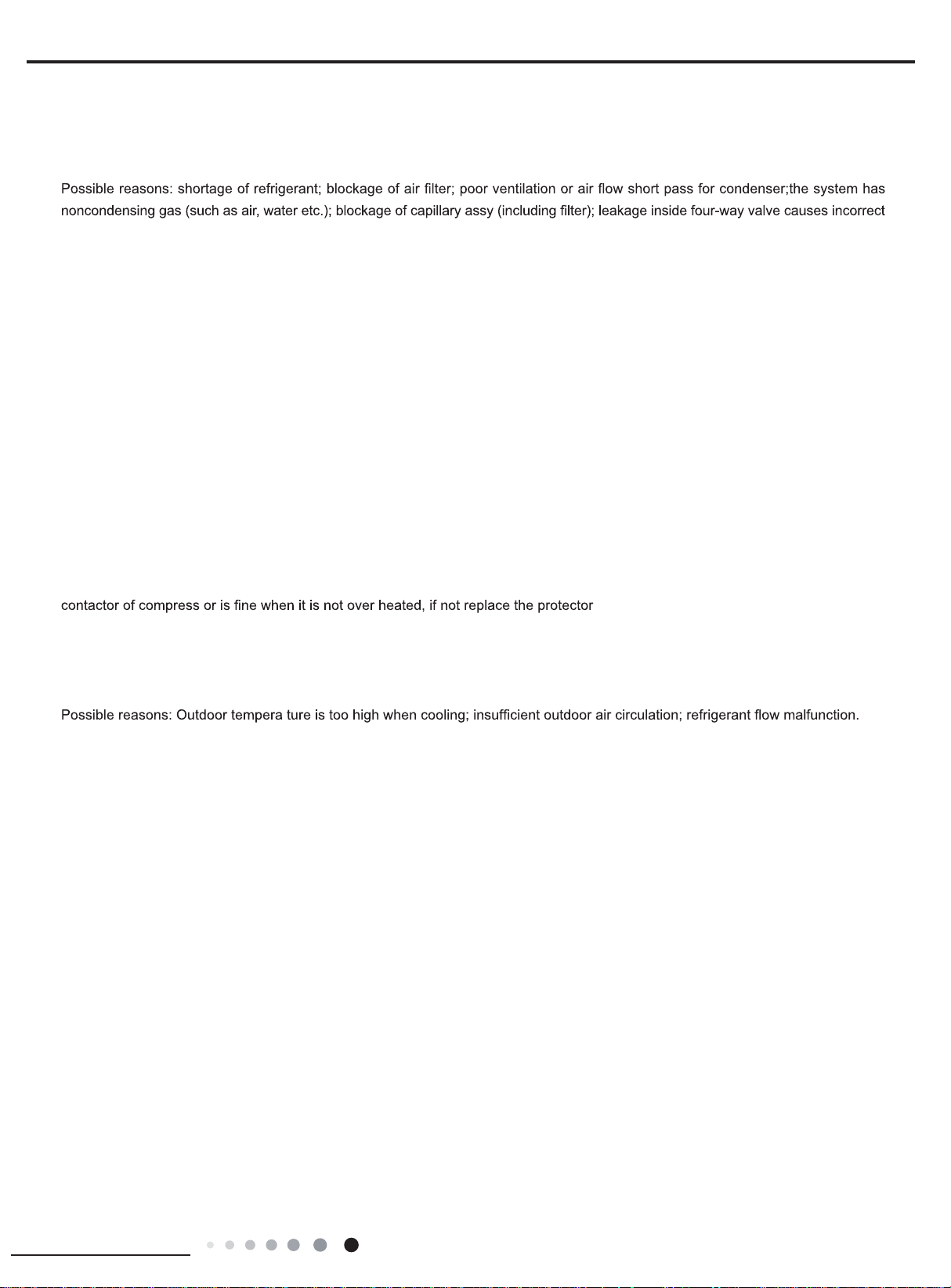
NO.
1
2
3
4
5
6
7
Malfunction
Name
High
pressure
protection of
system
Antifreezing
protection
High
discharge
temperature
protection of
compressor
Overcurrent
protection
Communication
Malfunction
High
temperature
resistant
protection
Internal
motor (fan
motor) do not
operate
Display Method of Indoor Unit
Dual-8
Display
Indicator Display (during
blinking, ON 0.5s and OFF 0.5s)
Code
E1
E2
E4
E5
E6
E8
H6
Operation
Indicator
OFF 3s
and blink
once
OFF 3S
and blink
twice
OFF 3S
and blink 4
times
OFF 3S
and blink 5
times
OFF 3S
and blink 6
times
OFF 3S
and blink 8
times
OFF 3S
and blink
11 times
Cool
Indicator
Heating
Indicator
Display Method of
Outdoor Unit
(Indicator has 3 kinds
of display status and
they will be displayed
circularly every 5s.)
□OFF
■Illuminated ƿBlink
D5
(D40)D6(D41)
D16
(D42)
D30
(D43)
ƶ ƿ ƿ ƿ
Ƶ ƶ Ƶ ƶ
Ƶ ƶ Ƶ ƿ
ƶ Ƶ ƿ ƶ
ƶ ƶ ƶ ƿ
Ƶ ƶ Ƶ Ƶ
A/C status Possible Causes
During cooling and drying
operation, except indoor
fan operates, all loads stop
operation.
During heating operation, the
complete unit stops.
During cooling and drying
operation, compressor and
outdoor fan stop while indoor
fan operates.
During cooling and drying
operation, compressor and
outdoor fan stop while indoor
fan operates. During heating
operation, all loads stop.
During cooling and drying
operation, compressor and
outdoor fan stop while indoor
fan operates. During heating
operation, all loads stop.
During cooling operation,
compressor stops while indoor
fan motor operates. During
heating operation, the complete
unit stops.
During cooling operation:
compressor will stop while
indoor fan will operate. During
heating operation, the complete
unit stops.
Internal fan motor, external fan
motor, compressor and electric
heater stop operation,guide
louver stops at present location.
Possible reasons:
1. Refrigerant was superabundant;
2. Poor heat exchange (including
and bad radiating environment );
Ambient temperature is too high.
1. Poor air-return in indoor unit;
2. Fan speed is abnormal;
3. Evaporator is dirty.
Please refer to the malfunction
analysis (discharge protection,
overload).
1. Supply voltage is unstable;
2. Supply voltage is too low and
load is too high;
3. Evaporator is dirty.
Refer to the corresponding
malfunction analysis.
Refer to the malfunction analysis
(overload, high temperature
resistant).
1. Bad contact of DC motor
feedback terminal.
2. Bad contact of DC motor
control end.
3. Fan motor is stalling.
4. Motor malfunction.
5. Malfunction of mainboard rev
detecting circuit.
1. No jumper cap insert on
Wireless remote receiver and
button are effective, but can
not dispose the related
command
During cooling and drying
operation, indoor unit operates
while other loads will stop;
during heating operation,
the complete unit will stop
operation.
During cooling and drying
operation, compressor will stop
while indoor fan will operate;
During heating operation, the
complete unit will stop
operation.
8
9
10
Malfunction
protection of
jumper cap
Indoor
ambient
temperature
sensor is
open/short
circuited
Overcurrent
protection of
phase
current for
compressor
C5
F1
P5
OFF 3S
and blink
15 times
OFF 3S
and blink
once
OFF 3S
and blink
15 times
ƶ ƿ ƶ ƶ
8
mainboard.
2. Incorrect insert of jumper cap.
3. Jumper cap damaged.
4. Abnormal detecting circuit of
mainboard.
1. Loosening or bad contact of
indoor ambient temp. sensor and
mainboard terminal.
2. Components in mainboard fell
down leads short circuit.
3. Indoor ambient temp. sensor
damaged.(check with sensor
resistance value chart)
4. Mainboard damaged.
Refer to the malfunction
analysis (IPM protection, loss
of synchronism protection and
overcurrent protection of phase
current for compressor.
Installation and Maintenance
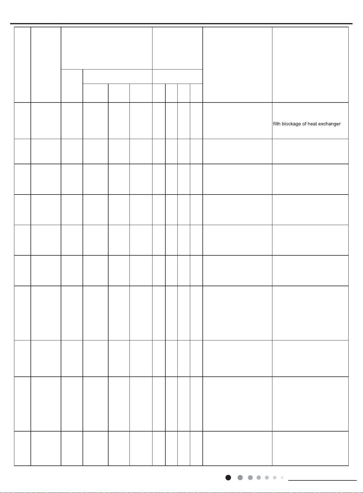
Page 9
Malfunction
n
position
y
normal
electrolytic
e
operation.
n
,
s
NO.
Name
Dual-8
Code
Display
Indoor
evaporator
temperature
11
sensor is
open/short
circuited
Outdoor
ambient
temperature
12
sensor is
open/short
circuited
Outdoor
condenser
temperature
13
sensor is
open/short
circuited
Outdoor
discharge
temperature
14
sensor is
open/short
circuited
Limit/
decrease
frequency
15
due to
overload
Decrease
frequency
16
due to
overcurrent
Decrease
frequency
due to
17
high air
discharge
Voltage for
18
19
DC bus-bar
is too high
Malfunction
of complete
units current
detection
PH
U5
Installation and Maintenance
Display Method of Indoor Unit
Indicator Display (during
blinking, ON 0.5s and OFF 0.5s)
Operation
Indicator
F2
F3
F4
F5
F6
F8
F9
Cool
Indicator
OFF 3S
and
blink
twice
OFF 3S
and
blink
3 times
OFF 3S
and
blink
4 times
OFF 3S
and
blink
5 times
OFF 3S
and
blink
for 6
times
OFF 3S
and
blink
8 times
OFF 3S
and
blink
9 times
OFF 3S
and
blink
11 times
OFF 3S
and
blink
13 times
Heating
Indicator
Display Method of
Outdoor Unit
(Indicator has 3 kinds
of display status and
they will be displayed
circularly every 5s.)
□OFF
■Illuminated
D5
(D40)D6(D41)
ƶ ƶ ƿ Ƶ
ƶ ƶ ƿ ƶ
ƿ
D16
(D42)
Blink
D30
(D43)
ƶ ƶ ƿ ƿ
Ƶ ƶ ƿ ƿ
Ƶ Ƶ ƶ Ƶ
Ƶ Ƶ ƶ ƶ
ƶ Ƶ ƶ ƿ
ƶ Ƶ ƿ Ƶ
A/C status Possible Causes
AC stops operation once
reaches the setting
temperature. Cooling, drying:
internal fan motor stops
operation while other loads
stop operation; heating: AC
stop operation
During cooling and drying
operating, compressor stops
while indoor fan operates;
During heating operation, the
complete unit will stop operation
During cooling and drying
operation, compressor stops
while indoor fan will operate;
During heating operation,
the complete unit will stop
operation.
During cooling and drying
operation, compressor will sop
after operating for about 3 mins,
while indoor fan will operate;
During heating operation, the
complete unit will stop after
operating for about 3 mins.
All loads operate normally, while
operation frequency for
compressor is decreased
All loads operate normally, while
operation frequency for
compressor is decreased
All loads operate normally, while
operation frequency for
compressor is decreased
During cooling and drying
operation, compressor will stop
while indoor fan will operate;
During heating operation, the
complete unit will stop
operation.
During cooling and drying
operation, the compressor will
stop while indoor fan will operate;
During heating operating,
the complete unit will stop
1. Loosening or bad contact of
Indoor
evaporator temp. sensor and
mainboard terminal.
2. Components on the mainboard
fall
down leads short circuit.
3. Indoor evaporator temp. sensor
damaged.(check temp. sensor
value
chart for testing)
4. Mainboard damaged.
Outdoor temperature sensor
hasnt been connected well or
is damaged. Please check it by
referring to the resistance table for
temperature sensor)
Outdoor temperature sensor
hasnt been connected well or
is damaged. Please check it by
referring to the resistance table for
temperature sensor)
1.Outdoor temperature sensor
hasnt been connected well or is
damaged. Please check it by
referring to the resistance table for
temperature sensor)
2.The head of temperature sensor
hasnt been inserted into the
copper tube
Refer to the malfunction analysis
(overload, high temperature
resistant)
The input supply voltage is too
low;
System pressure is too high and
overload
Overload or temperature is too
high;
Malfunction of electric expansio
valve (EKV)
1. Measure the voltage of
L and N on wiring board (XT), if
the voltage is higher than 265VAC,
turn on the unit after the suppl
voltage is increased to the
range.
2.If the AC input is normal,
measure the voltage of
capacitor C on control panel (AP1),
if its normal, theres malfunction
for the circuit, please replace th
control panel (AP1)
Theres circuit malfunction o
outdoor units control panel AP1
please replace the outdoor unit
control panel AP1.
9
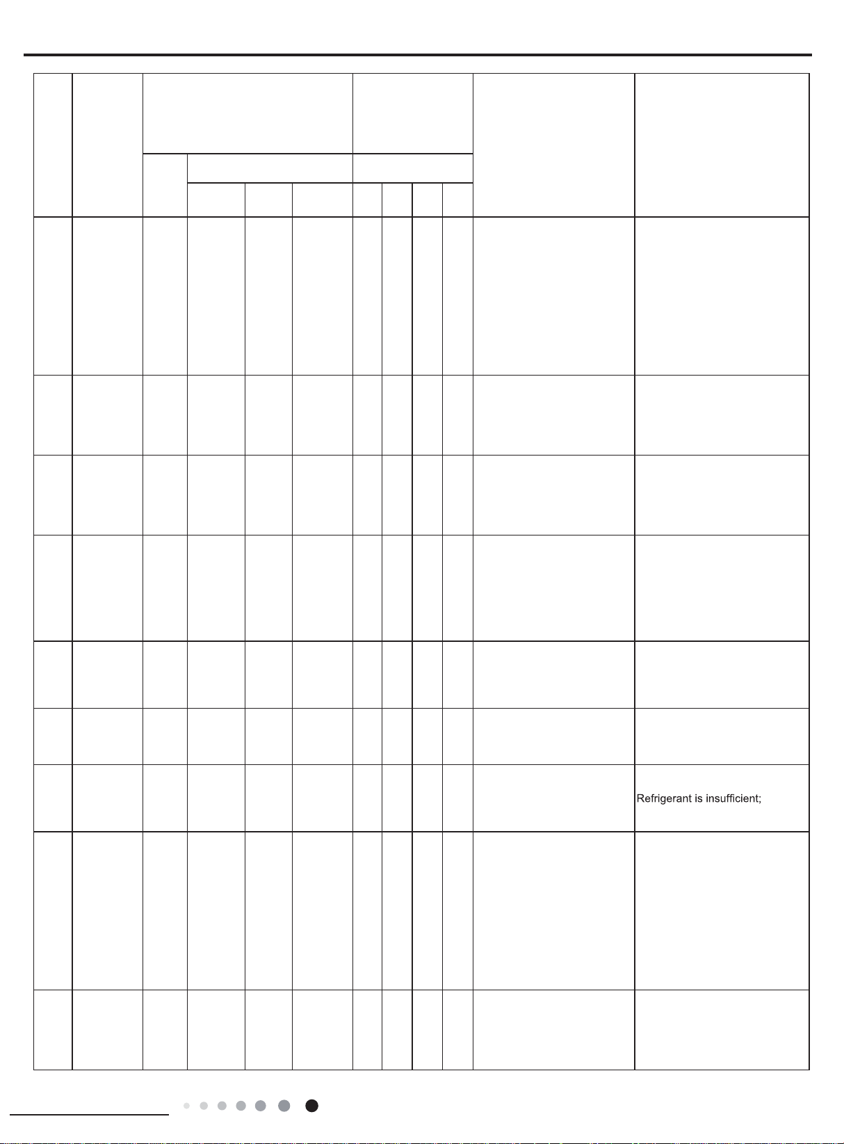
Page 10

Malfunction
nalysis
NO.
20 Defrosting H1
Name
Dual-8
Code
Display
Display Method of Indoor Unit
Indicator Display (during
blinking, ON 0.5s and OFF 0.5s)
Operation
Indicator
Cool
Indicator
Heating
Indicator
OFF 3S
and blink
once
Display Method of
Outdoor Unit
(Indicator has 3 kinds
of display status and
they will be displayed
circularly every 5s.)
□OFF
■Illuminated
D5
(D40)D6(D41)
ƿ
D16
(D42)
Blink
A/C status Possible Causes
D30
(D43)
Defrosting will occur in heating
mode. Compressor will operate
while indoor fan will stop
operation.
Its the normal state
21
22
23
24
25
26
27
28
29
Static
dedusting
protection
Overload
protection for
compressor
System is
abnormal
IPM
protection
PFC
protection
Desynchronizing of
compressor
Decrease
frequency
due to high
temperature
resistant
during
heating
operation
Failure startup
Malfunction
of phase
current
detection
circuit for
compressor
H2
H3
H4
H5
HC
H7
H0
LC
U1
OFF 3S
and blink
twice
OFF 3S
and blink
3 times
OFF 3S
and blink
4 times
OFF 3S
and blink
5 times
OFF 3S
and blink
6 times
OFF 3S
and blink
7 times
OFF 3S
and blink
10 times
OFF 3S
and blink
11 times
OFF 3S
and blink
13 times
ƶ ƿ ƿ ƶ
Ƶ ƶ Ƶ Ƶ
ƶ ƿ ƶ Ƶ
ƶ Ƶ ƿ ƿ
ƶ ƿ Ƶ ƿ
Ƶ ƶ ƿ ƿ
ƶ ƿ ƶ ƿ
ƶ ƿ Ƶ ƶ
During cooling and drying
operation, compressor will stop
while indoor fan will operate;
During heating operation, the
complete unit will stop
operation.
During cooling and drying
operation, compressor will stop
while indoor fan will operate;
During heating operation, the
complete unit will stop
operation.
During cooling and drying
operation, compressor will stop
while indoor fan will operate;
During heating operation, the
complete unit will stop
operation.
During cooling and drying
operation, compressor will stop
while indoor fan will operate;
During heating operation, the
complete unit will stop
operation.
During cooling and drying
operation, compressor will stop
while indoor fan will operate;
During heating operation, the
complete unit will stop
operation.
All loads operate normally, while
operation frequency for
compressor is decreased
During cooling and drying
operation, compressor will stop
while indoor fan will operate;
During heating operation, the
complete unit will stop
operation.
During cooling and drying
operation, compressor will stop
while indoor fan will operate;
During heating operation, the
complete unit will stop
/
1. Wiring terminal OVC-COMP
is loosened. In normal state, the
resistance for this terminal should
be less than 1ohm.
2.Refer to the malfunction a
( discharge protection, overload)
Refer to the malfunction analysis
(overload, high temperature
resistant)
Refer to the malfunction
analysis (IPM protection, loss
of synchronism protection and
overcurrent protection of phase
current for compressor.
Refer to the malfunction analysis
Refer to the malfunction
analysis (IPM protection, loss
of synchronism protection and
overcurrent protection of phase
current for compressor.
Refer to the malfunction analysis
(overload, high temperature
resistant)
Refer to the malfunction analysis
Replace outdoor control panel AP1
10
Installation and Maintenance
Page 11

NO.
capacitor C on control panel (AP1),
30
31
32
33
34
35
Malfunction
Name
EEPROM
malfunction
Charging
malfunction
of capacitor
Malfunction
of module
temperature
sensor circuit
Module high
temperature
protection
Malfunction
of voltage
dropping for
DC bus-bar
Voltage of
DC bus-bar
is too low
Display Method of Indoor Unit
Dual-8
Display
Indicator Display (during blinking,
ON 0.5s and OFF 0.5s)
Code
Operation
Indicator
EE
PU
P7
P8
U3
PL
Cool
Indicator
Heating
Indicator
OFF 3S
and blink
15 times
OFF 3S
and blink
17 times
OFF 3S
and blink
18 times
OFF 3S
and blink
19 times
OFF 3S
and blink
20 times
OFF 3S
and blink
21 times
Display Method of
Outdoor Unit
(Indicator has 3 kinds
of display status and
they will be displayed
circularly every 5s.)
□OFF
■Illuminated
D5
(D40)D6(D41)
D16
(D42)
ƿ
Blink
D30
(D43)
ƶ ƶ ƶ Ƶ
ƶ Ƶ ƶ Ƶ
ƶ ƶ Ƶ ƿ
Ƶ ƶ ƿ Ƶ
ƶ Ƶ Ƶ Ƶ
ƶ Ƶ Ƶ ƶ
A/C status Possible Causes
During cooling and drying
operation, compressor will stop
while indoor fan will operate;
During heating operation, the
complete unit will stop
During cooling and drying
operation, compressor will stop
while indoor fan will operate;
During heating operation, the
complete unit will stop
During cooling and drying
operation, compressor will stop
while indoor fan will operate;
During heating operation, the
complete unit will stop
During cooling operation,
compressor will stop while
indoor fan will operate; During
heating operation, the complete
unit will stop
During cooling and drying
operation, compressor will stop
while indoor fan will operate;
During heating operation, the
complete unit will stop
During cooling and drying
operation, compressor will stop
while indoor fan will operate;
During heating operation, the
complete unit will stop
Replace outdoor control panel
AP1
Refer to the part three—charging
malfunction analysis of capacitor
Replace outdoor control panel
AP1
After the complete unit is deenergized for 20mins, check
whether the thermal grease on
IPM Module of outdoor control
whether the radiator is inserted
tightly. If its no use, please replace
control panel AP1.
Supply voltage is unstable
1. Measure the voltage of position
L and N on wiring board (XT), if
the voltage is higher than 150VAC,
turn on the unit after the supply
voltage is increased to the normal
range.
2.If the AC input is normal,
measure the voltage of electrolytic
36
37
38
39
Limit/
decrease
frequency
due to high
temperature
of module
The four-way
valve is
abnormal
Zerocrossing
malfunction
of outdoor
unit
Limit/
decrease
frequency
due to
antifreezing
EU
U7
U9
FH
Ƶ Ƶ Ƶ ƿ
Ƶ ƶ ƿ ƶ
Ƶ Ƶ ƿ ƶ
Ƶ Ƶ Ƶ ƶ
All loads operate normally, while
operation frequency for
compressor is decreased
If this malfunction occurs during
heating operation, the complete
unit will stop operation.
During cooling operation,
compressor will stop while
indoor fan will operate; during
heating,the complete unit will
stop operation.
All loads operate normally, while
operation frequency for
compressor is decreased
if its normal, theres malfunction
for the circuit, please replace the
control panel (AP1)
Discharging after the complete
unit is de-energized for 20mins,
check whether the thermal grease
on
IPM Module of outdoor control
whether the radiator is inserted
tightly.
If its no use, please replace control
panel AP1.
1.Supply voltage is lower than
AC175V;
2.Wiring terminal 4V is loosened
or broken;
3.4V is damaged, please replace
4V.
Replace outdoor control panel
AP1
Poor air-return in indoor unit or fan
speed is too low
Installation and Maintenance
11
Page 12

4. How to Check Simply the Main Part
s
Indoor unit:
(1)Temperature sensor malfunction
Start
Is the wiring
terminal between temperature
sensor and the controller loosened or
poorly contacted?
yes
Insert the temperature
sensor tightly
no
no
Is there short circuit due to tri-pover
of the pa rts?
no
no
Is the temperature
sensor normal acc o rding to the
Resistance Table?
yes
no
M alfunction is
eliminated.
yes
Make the parts upright
Malfunction is
eliminated.
no
Replace it with a
temperature sensor
of the same model
Malfunction is
removed.
yes
ye
12
Replace the c ontroller with
one of the same model
End
yes
Installation and Maintenance
Page 13

(2)Indoor fan does not operate (H6)
s
Start
Pull the blade by
hand under
de-energization
status
Whether the
blade can operate
smoothly
Yes
Check whether the
wiring terminal between
indoor fan and main
board is loose
No
Energize and restart upthe
unit, test whether the voltage beween motor
terminal 1 and 2 is 280~310VDC
Yes
No
No
Yes
No
No
No
Adjust the motor and
blade assembly to let
the motor can operate
smoothly
Is malfunction
eliminated
Reinsert the wiring
terminal of indoor fan
Is malfunction
eliminated
It's the malfunction of
main board. Replace
the main board with
the same model
Is malfunction
eliminated
Yes
Ye
Yes
Installation and Maintenance
Test whether the voltage bewween motor
terminal 2 and 3 is 15VDC
Yes
Test whether there's voltage signal
beween motor terminal 2 and 4
Yes
It's the malfunction
of motor. Replace
the motor.
No
No
No
No
It's the malfunction of
main board. Replace
the main board with
the same model
Is malfunction
eliminated
It's the malfunction of
main board. Replace
the main board with
the same model
Is malfunction
eliminated
End
Yes
Yes
13
Page 14

(3)Jumper cap malfunction (C5)
C5 is dis played
on the unit.
Is there jumper cap on the
controller?
Yes
Is the jumper cap inserted
incorrectly or improperly?
No
Replace the jumper
cap
No
No Yes
No
Yes
Install a matching
Re-insert the jumper
jumper cap.
Is the
malfunction
eliminated?
cap
Is the
malfunction
eliminated?
14
Is the
malfunction
eliminated?
No
The mainboard is
defined abnormal;
replace it
End
Yes
Yes
Installation and Maintenance
Page 15

(4) Communication malfunction (E6)
Is there incorrect match
between the main board and the
display panel or between the indoor
and outdoor boards?
Poor contact of any line
may lead to communication
malfuntion.
Is there
incorrect connection?
Note:
1.Before replacing mainboard of indoor unit, make sure the mainboard for replacement is qualied. The following testes shall be done:
a.Check if protective tube FUSE 1 has open circuit. If so, replace it with a protective tube of the same model.
b.Energize the unit and check if buzzer is sound. If not, the mainboard of indoor unit can’t be used.
c.Energize the unit with display and check if all icons are displayed after energization and if the display is normal. If not, the main board can’t
be used.
2.The mainboard for replacement shall has the same model with the original mainboard, so do the jumper cap.
3.The wiring and assembly methods shall also be the same with that of the original mainboard when replacing the mainboard.
Installation and Maintenance
15
Page 16

(1) Capacity charging malfunction (outdoor unit malfunction) (AP1 below is control board of outdoor
Outdoor unit:
unit)
Main detection point:
● Detect if the voltage of L and N terminal of wiring board is between 210AC-240AC by alternating voltage meter;
● Is reactor (L) well connected? Is connection wire loosened or pull-out? Is reactor (L) damaged
"
Malfunction diagnosis process:
Turn on the unit
and wait 1 minute
Use DC voltmeter
to measure the
voltage on the two
ends of electrolytic
capacitor
Voltage higher than 200V?
N
Measure the AC voltage between
L and N on wiring board
terminal
XT(power supply)
Voltage within
210VAC~250VAC?
Y
Shut down the power and wait 20 mi
use DC voltmeter to measure the voltage
on the two ends of capacitor (test3), until
the voltage is lower than 20V
Check the
connection of reactor
(L in the Electrical
Wiring Diagram)
nutes; or
Y
N
Fault with the voltage
testing circuit on
control panel AP1
Shut down the power
and repair the power
supply to restore the
range
210VAC~250VAC
Replace the control
panel AP1
power on and
restart the unit
N
If the fault is
eliminated?
Y
16
If the wiring of
is normal?
reactor L
Y
Replace the control
panel AP1
End
Connect the reactor
Laccording to Elec-
N
trical Wiring Diagram correctly
Re-energize and
turn on the unit
N
If the fault is
eliminated?
Y
Installation and Maintenance
Page 17

(2) IPM protection, desynchronizing malfunction, phase current of compressor is overcurrent (AP1 below is control
board of outdoor unit)
Main detection point:
If control board AP1 and compressor COMP is well connected? If they are loosened? If the connection sequence is correct?
Is voltage input in the normal range (Test the voltage between L, N of wiring board XT by DC voltage meter)?
If coil resistance of compressor is normal? Is compressor coil insulating to copper pipe well?
If the work load of unit is heavy? If radiating of unit is well?
If the refrigerant charging is appropriate?
Malfunction diagnosis process:
Installation and Maintenance
17
Page 18

Energize and
p
A
switch on
IPM protection
occurs after the
machine has run for
eriod of time?
a
Please confirm:
1. If the indoor and
outdoor heat
exchangers are
dirty? If they are
obstructed by other
objects which affect
the heat exchange
of indoor and
outdoor unit.
2. If the indoor and
outdoor fans are
working normally?
3. If the environment
temperature is too
high, resulting in
that the system
pressure is too high
and exceeds the
permissible range?
4. If the charge
volume of
refrigerant is too
much, resulting in
that the system
pressure is too
high?
5. Other conditions
resulting in that the
system pressure
becomes too high.
Refer to the
Electrical Wiring
Diagram and check
if the connection
between AP1 and
COMP is loose and if
the connection order
is correct.
Use AC voltmeter
to measure the
voltage between
Y N
terminal L and N
on the wiring
board XT)
Voltage between
Y
the two ends of celectrolytic
capacitor is
higher than
250V
Stop the unit and
disconnect the power
supply. Then, check
the connection of
capacitor C2
according to Electrical
Wiring Diagram.
Remove the wires
on the two ends of
capacitor C2. Then,
use capacitance
meter to measure
the capacitor C2.
Verify as per the
Parameters Sheet.
If capacitor
C2 is failed?
N
If there is any
abnormality
described above?
Y
N
between the two ends of
capacitor C2, until the
voltage is lower than 20V
control panel AP1
If the voltage
between terminal L
and N on wiring
board XT is within
210VAC~250VAC?
Restart the unit. Before
protection occurs,
use DC voltmeter to
measure the voltage
between the two
ends of electrolytic
capacitor on control
panel AP1
The connection
of capacitor C2
is loose.
Stop the unit and
disconnect the power
supply. Wait 20 minutes,
or use DC voltmeter to
measure the voltage
Replace the capacitor
C2. Then, energize
and start the unit.
Replace the
Take corrective actions
according to Technical
Y
Service Manual, and
then energize and start
the unit.
Replace the
control panel AP1
Check the supply
voltage and
restore it to
210VAC~250VAC
N
Y
N
If the unit can
work
normally?
Reconnect the
capacitor C2 according
to Electrical Wiring
Diagram. Then,
Restart the
unit.
If the unit can
work normallv?
If the unit can
work normally?
N
If the unit can
work normally?
N
Y
Y
Y
Y
18
If the connection
between AP1 and
COMP is unsecure
or the connection
order is wrong?
Use ohmmeter to
measure the resistance
between the three
terminals on compressor
COMP, and compare the
measurements with the
compressor resistance on
Service Manual.
Use ohmmeter to
measure the resistance
between the two
terminals of compressor
COMP and copper tube.
Connect the control panel
P1 and compressor
Y
COMP correctly according
to the Electrical Wiring
Diagram. Then, energize
and start the unit.
If the
resistance is
normal?
Resistance higher
than 500MΩ?
Replace the
control panel
N
AP1
Replace the
compressor
COMP
N
If the unit can
work
normally?
END
Y
Installation and Maintenance
Page 19

(3) Diagnosis for anti-high temperature, overload protection (AP1 below is control board of outdoor unit)
Main detection point:
● If the outdoor ambient temperature is in normal range;
● If the indoor and outdoor fan is running normal;
● If the radiating environment of indoor and outdoor unit is well.
Malfunction diagnosis process:
Anti-high temperature,
overload protection
If the outdoor ambient temperature is
higher than 53 ºC?
Normal protection, please use
Y
it after improve the outdoor
ambient temperature
N
After the unit de-
energized for 20min
If the radiating of outdoor
and indoor unit is well?
N
If the indoor and outdoor
fan work well?
Y
Improve the
Y
N
radiating
environment of
unit
1. Check if fan terminal
OFAN is connected well
2. Test if resistance value
of any two terminals is less
than 1k with ohmic meter
Replace fan
Replace
capacitor C1
control board
AP1
Installation and Maintenance
Replace
outdoor fan
End
19
Page 20

(4) Diagnosis for failure start up malfunction (AP1 below is control board of outdoor unit)
Main detection point:
● If the compressor wiring is correct?
● If the stop time of compressor is enough?
● If the compressor is damaged?
● If the refrigerant charging is too much?
Malfunction diagnosis process:
Energize the unit
and start it
If the stop time of compressor
is more than 3min?
Y
If the stop time is not enough and the
N
high and low pressure of system is not
balance , please start it after 3min
If the compressor wire COMP(UVW) is
well connected and connection sequence
is correct
Y
If the refrigerant charging is
too much?
Y
Charge the
refrigerant according
to service manual
Does the unit start
up normally?
N
Replace control board AP1
Improve the connection situation
of control board AP1 and
N
compressor COMP, connect it
with wiring diagram
Does the unit start
N
up normally?
Y
20
If malfunction is
removed?
N
Replace the
compressor
End
Installation and Maintenance
Page 21

(5) Diagnosis for compressor synchronism (AP1 below is control board of outdoor unit)
Main detection point:
● If the system pressure is over-high?
● If the work voltage is over-low?
Malfunction diagnosis process:
Synchronism after
energize the unit
N
and start it
Synchronism
occurred during
operation
If the stop time of
compressor is more than
If the outdoor fan works
normally?
N
3min
Y
Y
N
If the compressor wire COMP(UVW) is well
connected, the connection sequence
forwards to clockwise direction?
Connect
wire well
Y
Replace
control board
AP1
Y
Remove
malfunction?
N
Replace
compressor
If the radiating of unit is
well?
N
If the input voltage of unit
is normal?
Y
If the refrigerant is too
much?
N
Replace
control board
AP1
Y
N
Y
Remove
malfunction?
End
N
Y
Check if the fan
terminal OFAN is
connected well
Improve the radiating
of unit (clean heat
exchanger and
increase ventilation)
Start to run until the
power resume normal
voltage
Charge the
refrigerant with
service manual
Replace fan
capacitor C1
Replace
outdoor fan
Installation and Maintenance
Replace
compressor
End
21
Page 22

(6) Diagnosis for overload and discharge malfunction (AP1 below is control board of outdoor unit)
Main detection point:
● If the electron expansion valve is connected well? Is the expansion valve damaged
?
● If the refrigerant is leakage?
● If the overload protector is damaged?
Malfunction diagnosis process:
After the unit
de-energized
for 20min
N
Replace
overload
protector SAT
If the overload protector SAT
is well connected?
Y
Under ambient temperature, test the
resistance of overload protector with ohmic
Y
If the wiring terminal FA of electron
expansion is well connected?
Y
The resistance value of
first 4 l ead foot an d th e
fif th lead foot is similar,
less than 100
Replace EKV
coil of electron
expansion valve
N
Connect wire
N
well with wiring
diagram
22
Remove
malfunction?
N
Check refrigerant, if there is
leakage, please refer to
specification
Remove
malfunction?
N
Replace
control board
AP1
End
Y
Installation and Maintenance
Page 23

(7) PFC (correction for power factor) malfunction (outdoor unit malfunction) (AP1 below is control board of outdoor
unit
)
Main detection point:
● Check if reactor (L) of outdoor unit and PFC capacity are damaged.
Malfunction diagnosis process:
Start
Check the
connection wire
of reactor (L) of
outdoor unit and
PFC capacity
Replace
If there is damaged
short circuit
N
Remove PFC capacity
and test resistance of
two terminals
If the resistance
value is 0
N
Cut the terminal of reactor,
test the resistance
between two terminals of
reactor with ohmic meter
Y
Y
Capacity is
circuit and
replace it
wire with circuit
short
connection
diagram
N
Re-energize
the unit and
start it
N
If the malfunction is
removed?
If the malfunction is
removed?
Y
If there is damaged
short circuit
control board
Installation and Maintenance
N
Replace
AP1
End
Y
Replace the
reactor
Re-
energize
the unit and
start it
N
If the malfunction is
removed?
Y
Y
23
Page 24

(8) Communication malfunction (AP1 below is control board of outdoor unit)
Main detection point:
● Check if the connection wire and the built-in wiring of indoor and outdoor unit is connected well and no damaged
● If the communication circuit of indoor mainboard is damaged? If the communication circuit of outdoor mainboard (AP1) is damaged
Malfunction diagnosis process:
Start
;
If the unit is operation
Y
normal before malfunction
N
Check connection
wire of indoor and
outdoor unit with
circuit diagram
Check built-
in wiring of
indoor and
outdoor unit
Y
N
Malfunction of
circuit is
detected with
control board
AP1 voltage
If the malfunction
is removed?
Y
N
If the wiring is
damaged?
N
Check communication
circuit of outdoor unit
Connection
correct?
N
Check connection
wire of indoor and
outdoor unit with
circuit diagram
If the malfunction
is removed?
Problem of
communication
circuit
N
Y
Replace outdoor
mainboard AP11
If the
malfunction is
removed?
Replace indoor
N
board
24
Y
Y
End
Y
Installation and Maintenance
Page 25

5. Troubleshooting for Normal Malfunction
1. Air Conditioner can't Be Started Up
Possible Causes Discriminating Method (Air conditioner Status) Troubleshooting
Conrm whether it's due to power failure. If yes,
No power supply, or poor
connection for power plug
Wrong wire connection between
indoor unit and outdoor unit,
or poor connection for wiring
terminals
Electric leakage for air conditioner
Model selection for air switch is
improper
Malfunction of remote controller
2. Poor Cooling (heating) for Air Conditioner
Possible Causes Discriminating Method (Air conditioner Status) Troubleshooting
Set temperature is improper Observe the set temperature on remote controller Adjust the set temperature
Rotation speed of the IDU fan
motor is set too low
Filter of indoor unit is blocked Check the lter to see it's blocked Clean the lter
Installation position for indoor unit
and outdoor unit is improper
Refrigerant is leaking
Malfunction of 4-way valve Blow cold wind during heating Replace the 4-way valve
Malfunction of capillary
Flow volume of valve is
insufcient
Malfunction of horizontal louver Horizontal louver can’t swing
Malfunction of the IDU fan motor The IDU fan motor can’t operate
Malfunction of the ODU fan motor The ODU fan motor can't operate
Malfunction of compressor Compressor can't operate
After energization, operation indicator isn’t bright
and the buzzer can't give out sound
Under normal power supply circumstances,
operation indicator isn't bright after energization
After energization, room circuit breaker trips off at
once
After energization, air switch trips off Select proper air switch
After energization, operation indicator is bright,
while no display on remote controller or buttons
have no action.
Small wind blow Set the fan speed at high or medium
Check whether the installation postion is proper
according to installation requirement for air
conditioner
Discharged air temperature during cooling is
higher than normal discharged wind temperature;
Discharged air temperature during heating is
lower than normal discharged wind temperature;
Unit's pressure is much lower than regulated
range
Discharged air temperature during cooling is
higher than normal discharged wind temperature;
Discharged air temperature during heating is
lower than normal discharged wind temperature;
Unit't pressure is much lower than regulated
range. If refrigerant isn’t leaking, part of capillary
is blocked
The pressure of valves is much lower than that
stated in the specication
wait for power recovery. If not, check power
supply circuit and make sure the power plug is
connected well.
Check the circuit according to circuit diagram
and connect wires correctly. Make sure all
wiring terminals are connected rmly
Make sure the air conditioner is grounded
reliably
Make sure wires of air conditioner is connected
correctly
Check the wiring inside air conditioner. Check
whether the insulation layer of power cord is
damaged; if yes, place the power cord.
Replace batteries for remote controller
Repair or replace remote controller
Adjust the installation position, and install the
rainproof and sunproof for outdoor unit
Find out the leakage causes and deal with it.
Add refrigerant.
Replace the capillary
Open the valve completely
Refer to point 3 of maintenance method for
details
Refer to troubleshooting for H6 for maintenance
method in details
Refer to point 4 of maintenance method for
details
Refer to point 5 of maintenance method for
details
3. Horizontal louver can't Swing
Possible Causes Discriminating Method (Air conditioner Status) Troubleshooting
Wrong wire connection, or poor
connection
Stepping motor is damaged Stepping motor can't operate Repair or replace stepping motor
Main board is damaged
Installation and Maintenance
Check the wiring status according to circuit
diagram
Others are all normal, while horizontal louver
can't operate
Connect wires according to wiring diagram to
make sure all wiring terminals are connected
rmly
Replace the main board with the same model
25
Page 26

4. ODU Fan Motor can't Operate
Possible causes
Wrong wire connection, or poor
connection
Capacity of the ODU fan motor is
damaged
Power voltage is a little low or
high
Motor of outdoor unit is damaged
5. Compressor can't Operate
Possible causes
Wrong wire connection, or poor
connection
Capacity of compressor is
damaged
Power voltage is a little low or
high
Coil of compressor is burnt out
Cylinder of compressor is blocked Compressor can't operate Repair or replace compressor
Discriminating method (air conditioner status) Troubleshooting
Check the wiring status according to circuit
diagram
Measure the capacity of fan capacitor with an
universal meter and nd that the capacity is out of
the deviation range indicated on the nameplate of
fan capacitor.
Use universal meter to measure the power supply
voltage. The voltage is a little high or low
When unit is on, cooling/heating performance
is bad and ODU compressor generates a lot of
noise and heat.
Discriminating method (air conditioner status) Troubleshooting
Check the wiring status according to circuit
diagram
Measure the capacity of fan capacitor with an
universal meter and nd that the capacity is out of
the deviation range indicated on the nameplate of
fan capacitor.
Use universal meter to measure the power supply
voltage. The voltage is a little high or low
Use universal meter to measure the resistance
between compressor terminals and it's 0
Connect wires according to wiring diagram to
make sure all wiring terminals are connected
rmly
Replace the capacity of fan
Suggest to equip with voltage regulator
Change compressor oil and refrigerant. If no
better, replace the compressor with a new one
Connect wires according to wiring diagram to
make sure all wiring terminals are connected
rmly
Replace the compressor capacitor
Suggest to equip with voltage regulator
Repair or replace compressor
6. Air Conditioner is leaking
Possible causes
Drain pipe is blocked Water leaking from indoor unit
Drain pipe is broken Water leaking from drain pipe Replace drain pipe
Wrapping is not tight
7. Abnormal Sound and Vibration
Possible causes Discriminating method (air conditioner status) Troubleshooting
When turn on or turn off the unit,
the panel and other parts will
expand and there's abnormal
sound
When turn on or turn off the unit,
there's abnormal sound due
to ow of refrigerant inside air
conditioner
Foreign objects inside the indoor
unit or there're parts touching
together inside the indoor unit
Foreign objects inside the outdoor
unit or there're parts touching
together inside the outdoor unit
Short circuit inside the magnetic
coil
Abnormal shake of compressor Outdoor unit gives out abnormal sound
Abnormal sound inside the
compressor
Discriminating method (air conditioner status) Troubleshooting
Eliminate the foreign objects inside the drain
pipe
Water leaking from the pipe connection place of
indoor unit
There's the sound of "PAPA"
Water-running sound can be heard
There's abnormal sound fro indoor unit
There's abnormal sound fro outdoor unit
During heating, the way valve has abnormal
electromagnetic sound
Abnormal sound inside the compressor
Wrap it again and bundle it tightly
Normal phenomenon. Abnormal sound will
disappear after a few minutes.
Normal phenomenon. Abnormal sound will
disappear after a few minutes.
Remove foreign objects. Adjust all parts'
position of indoor unit, tighten screws and stick
damping plaster between connected parts
Remove foreign objects. Adjust all parts'
position of outdoor unit, tighten screws and
stick damping plaster between connected parts
Replace magnetic coil
Adjust the support foot mat of compressor,
tighten the bolts
If add too much refrigerant during maintenance,
please reduce refrigerant properly. Replace
compressor for other circumstances.
26
Installation and Maintenance
Page 27

www.cooperandhunter.us
 Loading...