

Page 1
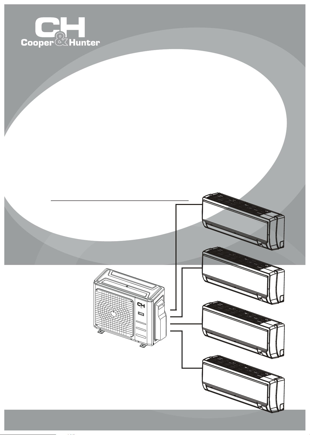
SOPHIA
MULTI-ZONE
INVERTER
SPLIT AIR CONDITIONER
WITH HEAT PUMP
INSTALLATION MANUAL
OUTDOOR UNIT
Models:
CH-18MSPH-230VO
CH-28MSPH-230VO
CH-36MSPH-230VO
CH-48MSPH-230VO
IMPORTANT NOTE:
•
Read this manual carefully before
installing or operating your new air
conditioning unit. Make sure to save
this manual for future reference.
•
This manual only describes the installation of
the outdoor unit. When installing the indoor unit,
refer to the installation manual of the indoor unit.
Page 2
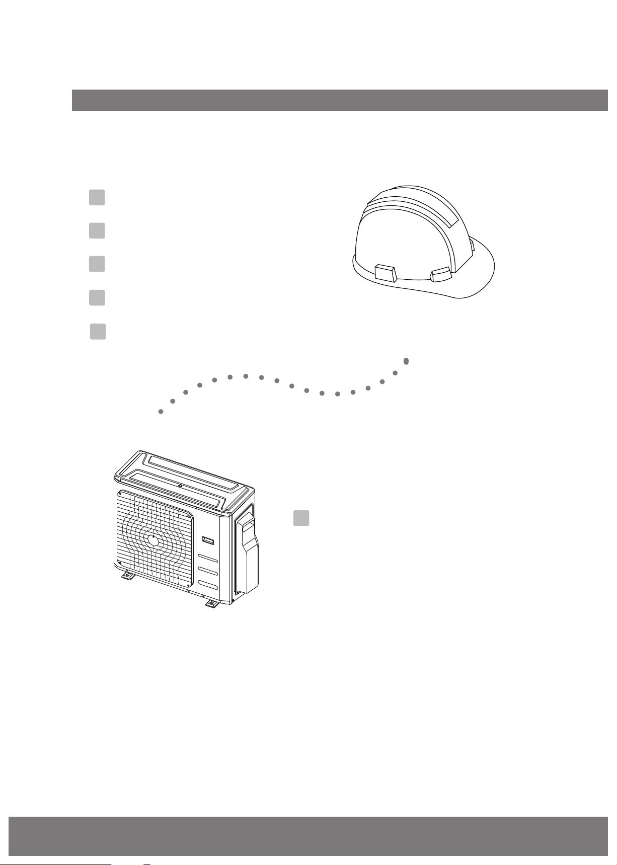
Table of Contents
Installation Manual
1
Accessories
2
Safety Precautions
3
Installation Overview
4
Installation Diagram
5
Specications
....................................................................
.................................................
..........................................
............................................
..............................................................
04
05
06
07
08
6
Outdoor Unit Installation ................................. 09
A. Outdoor Unit Installation Instructions ....... 09
B. Drain Joint Installation ........................................... 11
C. Notes on Drilling the Hole in the Wall ....... 11
D. When Selecting a 24K Indoor Unit ............... 11
Page 3
Refrigerant Piping Connection .................. 12
7
L N
9
Air Evacuation
.......................................................
A. Evacuation Instructions
B. Note on Adding Refrigerant
.................................
......................
20
20
8
Wiring
A. Outdoor Unit Wiring
B. Wiring Figure
................................................................
..........................
..........................................
MC MC
14
14
16
10
Test Run
11
Function of Automatic Wiring/Piping Correction
........................................................................................................................2122
.........
23
Page 3
Page 4
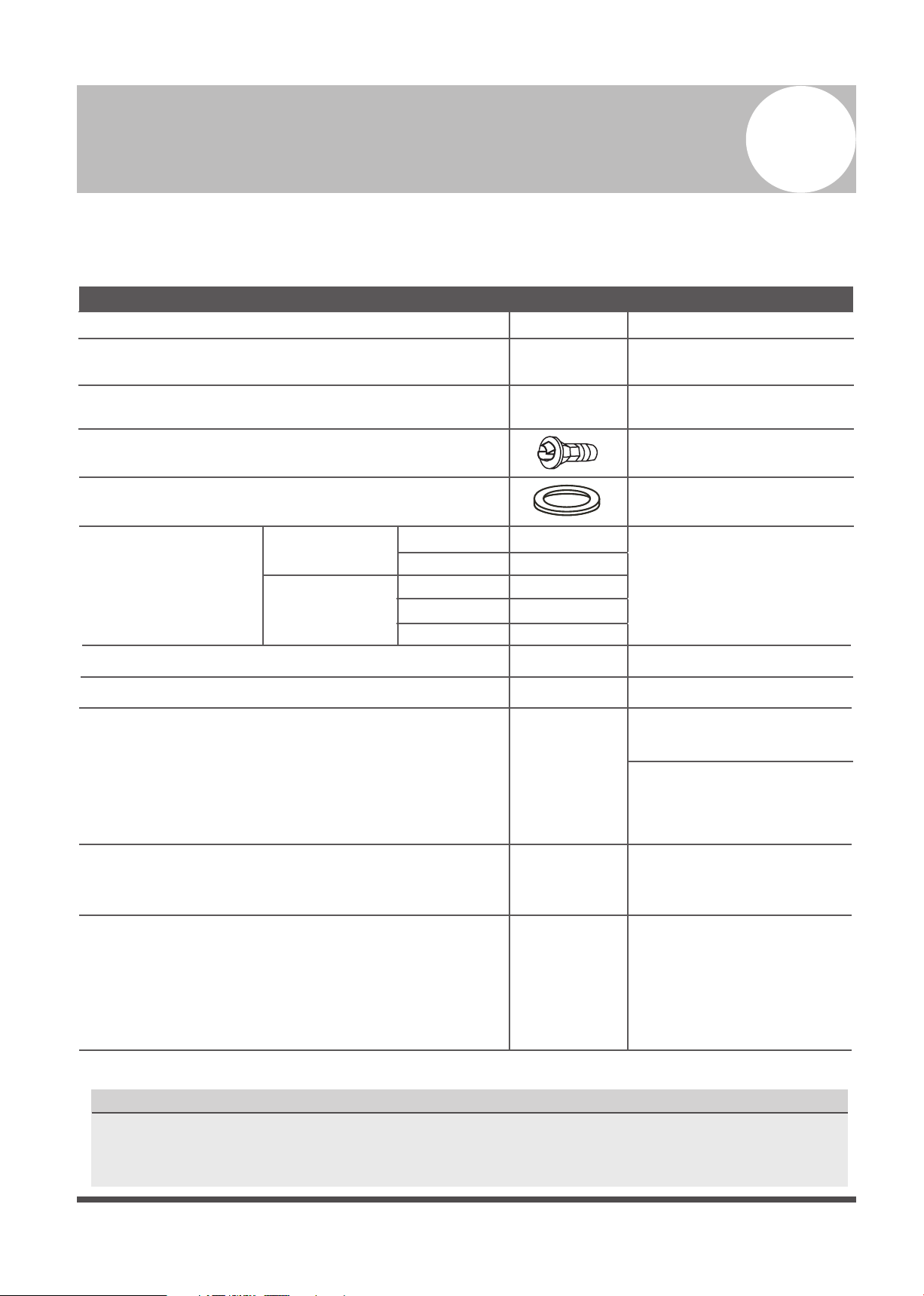
Accessories
1
The air conditioning system comes with the following accessories. Use all of the installation parts and
accessories to install the air conditioner. Improper installation may result in water leakage, electrical
shock, or fire, or cause the equipment to fail.
Name Shape Quantity
Installation plate
1
Plastic expansion sheath
Self-tapping screw AST3.9X25
Drain joint (some models)
Seal ring (some models)
Connecting
pipe
assembly
User’s manual
Installation manual
Transfer connector (packed with the indoor unit
or outdoor unit, depending on the model)
(NOTE: Pipe sizes dier from appliance to appliance.
To meet dierent pipe size requirements, sometimes a
transfer connector must be installed on the outdoor
Magnetic ring
(After installation, hitch this on the connective cable
between the indoor and outdoor units.)
Liquid side
Gas side
unit.)
Ø 6.35
Ø 9.52
Ø 9.52
Ø 12.7
Ø 15.9
5-8
(depending on the models)
5-8
(depending on the models)
1
1
Parts you must purchase
(consult your technician
for the proper size)
1
1
Optional part
(one piece per indoor unit)
Optional part
(1-5 pieces per outdoor unit,
depending on the model)
Optional part
(One piece per cable)
Cord protection rubber ring
(If the cord clamp cannot fasten the cord
because the cord is too small, wrap the cord
protection rubber ring (supplied with the
accessories) around the cord. Then x it with
the cord clamp.)
Optional Accessories
There are two types of remote controls: wired and wireless.
Select a remote control according to the customer's request and install it in an appropriate place.
To select a suitable remote control, refer to catalogues and technical literature.
Page 4
(on some models)
1
Page 5
Safety Precautions
Failure to observe a warning may result in death. The appliance must be installed in
accordance with national regulations.
Failure to observe a caution may result in injury or equipment damage.
Read safety precautions before installation
Incorrect installation due to ignoring instructions can cause serious damage or injury.
The seriousness of potential damage or injuries is classified as either a WARNING or CAUTION.
WARNING
CAUTION
WARNING
2
• Carefully read the safety precautions before installation.
• In certain functional environments, such as kitchens, server rooms, etc., the use of specially
designed air-conditioning units is highly recommended.
• Only trained and certied technicians should install, repair, and service this air
conditioning unit.
• Improper installation may result in electrical shock, short circuit, leaks, fire, or other damage to
equipment and personal property.
• Strictly follow the installation instructions set forth in this manual.
• Before you install the unit, consider strong winds, typhoons, and earthquakes that might aect
your unit and locate it accordingly. Failure to do so could cause damage to the unit.
• After installation, ensure there are no refrigerant leaks and that the unit is operating properly.
Refrigerant is toxic and flammable and poses a serious health and safety risk.
Note about Fluorinated Gasses
1. This air conditioning unit contains fluorinated gasses. For specific information on the type of gas
and the amount, please refer to the relevant label on the unit itself.
2. Installation, service, maintenance, and repair of this unit must be performed by a certified
technician.
3. Product uninstallation and recycling must be performed by a certified technician.
4. If the system has a leak-detection system installed, it must be checked for leaks at least every 12
months.
5.
When the unit is checked for leaks, proper record-keeping of all checks is strongly recommended.
Page 5
Page 6
Unit Installation
L N
Overview
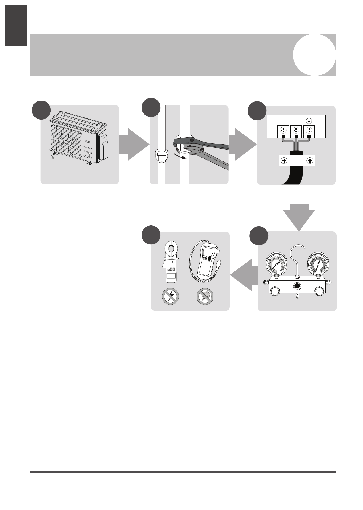
Installation Overview
3
INSTALLATION ORDER
1
Install the outdoor unit
(Page 9)
2
Connect the refrigerant pipes
(Page 12)
5
3
Connect the wires
(Page 14)
4
MC MC
Page 6
Perform a test run
(Page 22)
Evacuate the refrigeration
system
(Page 20)
Page 7
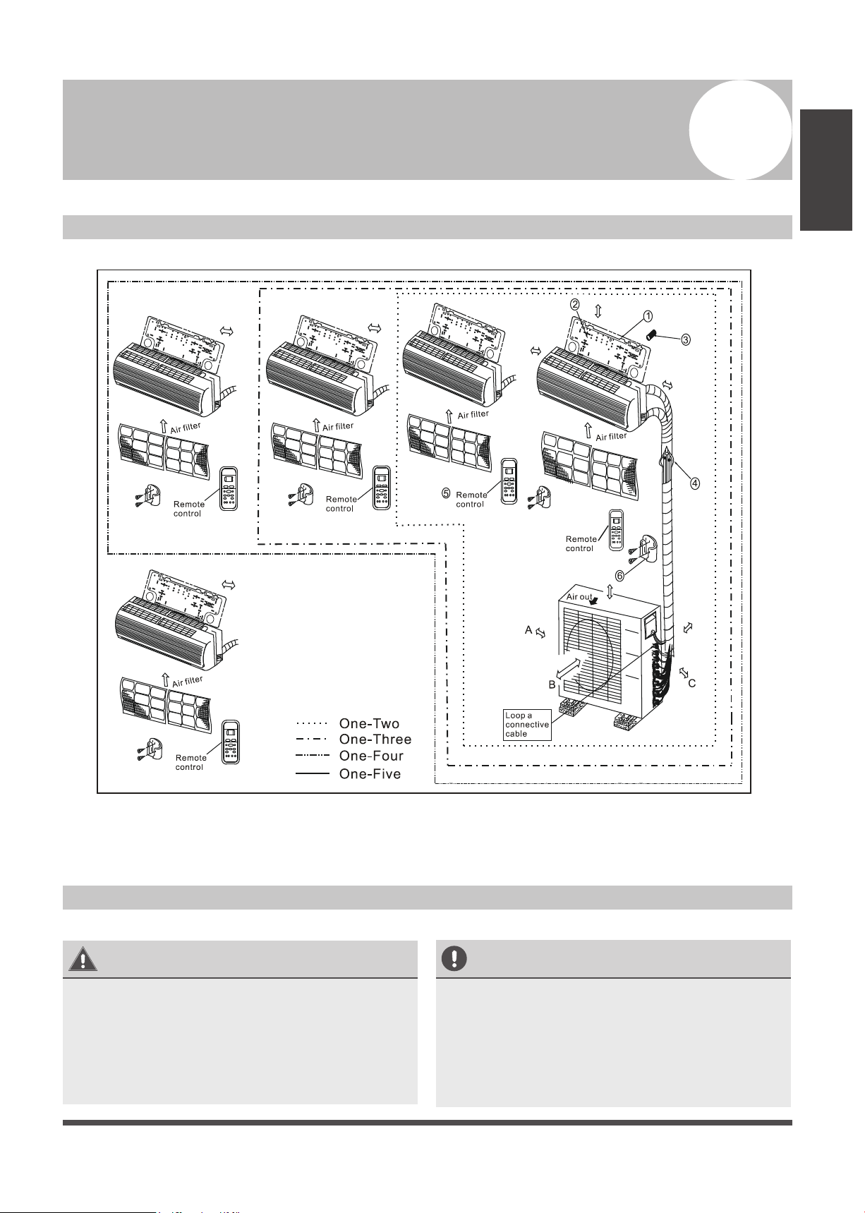
Installation Diagram
Installation Diagram
4
Installation
Diagram
More than 4.7 in (12 см)
More than 4.7 in (12 см)
More than 4.7 in (12 см)
More than 4.7 in
(12 см)
More than
3.9 in (10 см)
More than 78.7 in (200 см)
More than 5.9 in (15 см)
More than 4.7 in
(12 см)
(60 см)
More than 23.6 in
More than
11.8 in (30 см)
More than
23.6 in (60 см)
Safety Precautions
CAUTION
• This illustration is for explanation purposes
only. The actual shape of your air
condtioner may be slightly dierent.
•
Copper lines must be insulated
independently.
Fig. 4.1
CAUTION
• To prevent unnecessary damage to the wall,
use a stud nder to locate studs.
A minimum pipe run of 9.8 ft (3 m) is required
•
to minimize vibration and excessive noise.
•
Two of the A, B, and C directions should be
free from obstructions.
Page 7
Page 8
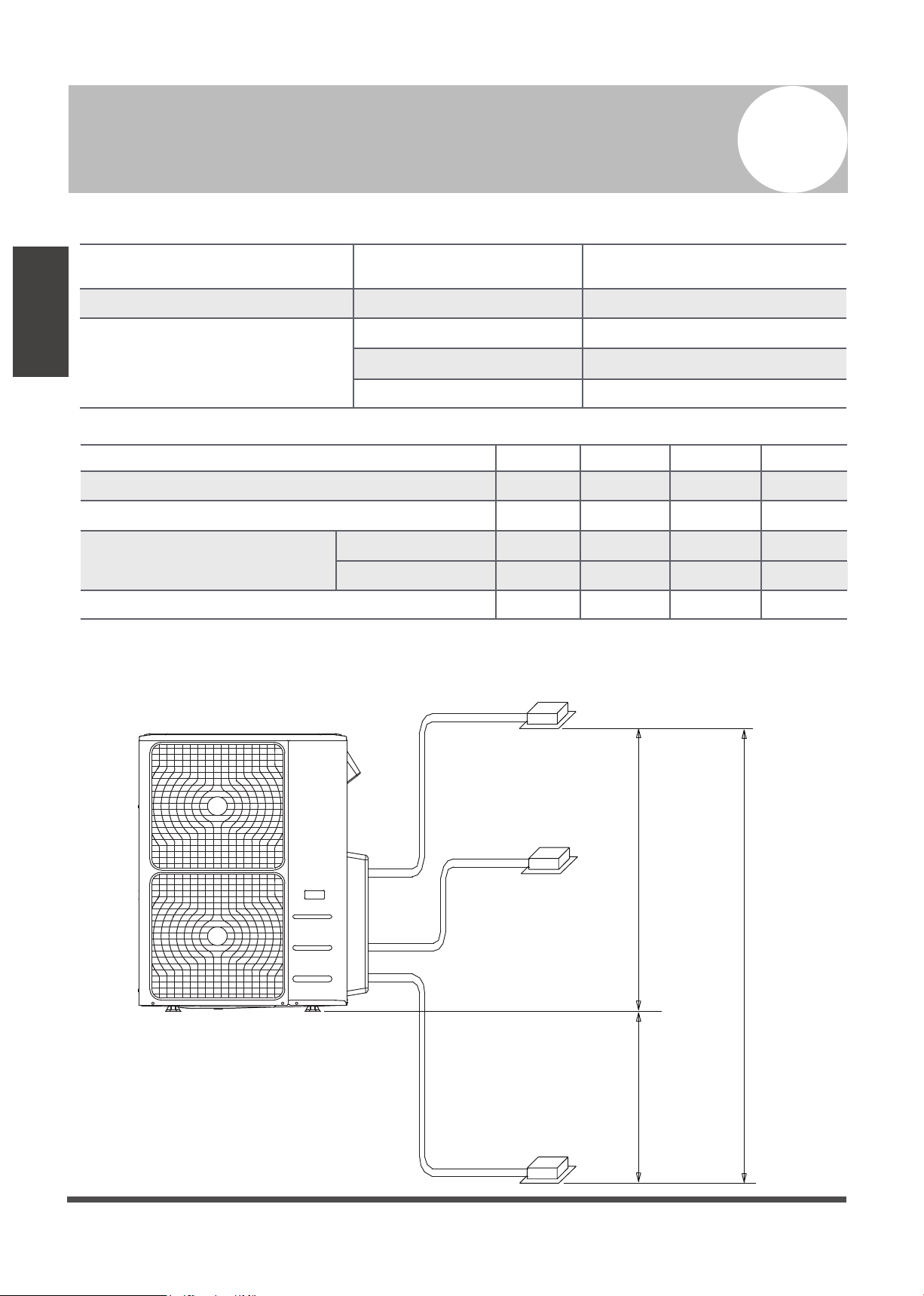
Specications
Table 5.1
5
Specications
Indoor units that can be used in
combination
Compressor stop/start frequency Stop time 3 minutes or more
Power source voltage
Table 5.2
Max. length for all rooms 98.4/30 147.6/45
Max. length for one indoor unit 65.6/20 82/25
Max. height dierent between
indoor and outdoor unit
Max. height dierence between indoor units
When installing multiple indoor units to a single outdoor unit, ensure that the length of the refrigerant
pipe and the drop height between the indoor and outdoor units meet the following requirements:
Outdoor unit
Number of connected
units
Voltage uctuation within ± 10% of rated voltage
Voltage drop during start within ± 15% of rated voltage
Interval unbalance within ± 3% of rated voltage
1 drive 2 1 drive 3
OU higher than IU
OU lower than IU 49/15 49/15
32.8/10 32.8/10
32.8/10 32.8/10
Indoor unit
1-5 units
Unit: ft/m
1 drive 4 1 drive 5
196.8/60 246/75
98.4/30 98.4/30
32.8/10 32.8/10
49/15 49/15
32.8/10 32.8/10
Max. height dierence
Outdoor Unit
Page 8
Indoor unit
49ft (15m)
49ft (15m)
32.8ft (10m)
Indoor unit
Page 9

Outdoor Unit Installation
Outdoor Unit Installation Instructions
Step 1: Select installation location
When choosing a location to install the outdoor
unit, consider the following:
√
Place the outdoor unit as close to the indoor
unit as possible.
√
Ensure that there is enough room for
installation and maintenance.
√
The air inlet and outlet must not be
obstructed or exposed to strong wind.
√
Ensure the location of the unit will not be
subject to snowdrifts, accumulation of leaves,
or other seasonal debris. If possible, provide
an awning for the unit. Ensure the awning
does not obstruct airflow.
√
The installation area must be dry and well
ventilated.
√
There must be enough room to install the
connecting pipes and cables and to access
them for maintenance.
6
√
The area must be free of combustible gases
and chemicals.
√
The pipe length between the outdoor and
indoor units must not exceed the maximum
allowable pipe length.
√
If possible, DO NOT install the unit where it
will be exposed to direct sunlight.
√
If possible, make sure the unit is located far
away from your neighbors’ property so that
the noise from the unit will not disturb them.
√
If the location is exposed to strong winds (for
example, near a seaside), place the unit
against the wall to shelter it from the
wind. If necessary, use an awning
(see Fig. 6.1 & 6.2).
√
Install the indoor and outdoor units, cables,
and wires at least 1 meter from televisions or
radios to prevent static or image distortion.
Depending on the radio waves, a 39.3 in (1 meter)
distance may not be enough to eliminate all
interference.
Outdoor Unit
Installation
Strong wind
Fig. 6.1
Step 2: Install outdoor unit
Fix the outdoor unit with anchor bolts (M10)
>23.6”/60 cm
Fix with bolts
Strong wind
Fig. 6.2
CAUTION
• Be sure to remove any obstacles that
may block air circulation.
• Be sure to refer to Length
Specifications to ensure there is
enough room for installation and
maintenance.
Fig. 6.3
Page 9
Page 10

Split Type Outdoor Unit
(Refer to Fig 6.4, 6.5, 6.6, 6.10, and Table 6.1)
Table 6.1: Length Specications of Split Type
Outdoor Unit (unit: inch/mm)
Outdoor Unit
Installation
W
Fig. 6.4
W
H
Outdoor Unit Dimensions
W x H x D
760 x 590 x 285 (29.9 x 23.2 x 11.2) 20.85 (530) 11.4 (290)
810 x 558 x 310 (31.9 x 22 x 12.2) 21.6 (549) 12.8 (325)
845 x 700 x 320 (33.27 x 27.5 x 12.6) 22 (560) 13.2 (335)
900 x 860 x 315 (35.4 x 33.85 x 12.4) 23.2 (590) 13.1 (333)
945 x 810 x 395 (37.2 x 31.9 x 15.55) 25.2 (640) 15.95 (405)
990 x 965 x 345 (38.98 x 38 x 13.58) 24.58 (624) 14.4 (366)
938 x 1369 x 392 (36.93 x 53.9 x 15.43) 24.96 (634) 15.9 (404)
900 x 1170 x 350 (35.4 x 46 x 13.8) 23.2 (590) 14.88 (378)
800 x 554 x 333 (31.5 x 21.8 x 13.1) 20.24 (514) 13.39 (340)
845 x 702 x 363 (33.27 x 27.6 x 14.3)
946 x 810 x 420 (37.2 x 31.9 x 16.53) 26.5 (673)
946 x 810 x 410 (37.2 x 31.9 x 16.14) 26.5 (673)
952 x 1333 x 410 (37.5 x 52.5 x 16.14) 24.96 (634)
952 x 1333 x 415 (37.5 x 52.5 x 16.14) 24.96 (634)
Mounting Dimensions
Distance A Distance B
21.26 (540)
13.8 (350)
15.87 (403)
15.87 (403)
15.9 (404)
15.9 (404 )
D
H
Fig. 6.5
A
B
Page 10
Fig. 6.6
Page 11

NOTE: The minimum distance between the
outdoor unit and walls described in the
installation guide does not apply to airtight
rooms. Be sure to keep the unit unobstructed
in at least two of the three directions
(M, N, and P) (see Fig. 6.7).
23.6”/60 cm above
Notes on Drilling the Hole in the Wall
You must drill a hole in the wall for the
refrigerant piping and the signal cable that will
connect the indoor and outdoor units.
Determine the location of the wall hole
1.
based on the location of the outdoor unit.
Using a 2.5” (65 mm) core drill, drill a hole
2.
in the wall.
11.8”/30 cm on left
M
78”/200 cm in front
N
11.8”/30 cm from back wall
23.6”/60 cm on right
P
Fig. 6.7
Drain Joint Installation
Before bolting the outdoor unit in place, install
the drain joint at the bottom of the unit.
(See Fig. 6.8)
1. Fit the rubber seal on the end of the drain
joint that will connect to the outdoor unit.
2. Insert the drain joint into the hole in the
base pan of the unit.
3. Rotate the drain joint 90° until it clicks in
place facing the front of the unit.
4. Connect a drain hose extension (not
included) to the drain joint to redirect water
from the unit during heating mode.
NOTE: Make sure the water drains to a safe
location where it will not cause water damage
or a slipping hazard.
NOTE: When drilling the wall hole, make
sure to avoid wires, plumbing, and other
sensitive components.
3.
Place the protective wall cu in the hole.
This will protect the edges of the hole and will
help seal it when you nish the installation
process.
When Selecting a 24K Indoor Unit
The 24K indoor unit can only be connected with an
A system. If there are two 24K indoor units, they
can be connected with an A and B system
(see Fig. 6.9).
Table 6.2: Connective pipe size of an A and B
system (unit: inch)
Indoor Unit capacity
(Btu/h)
Liquid Gas
7K/9K/12K 1/4 3/8
12K/18K 1/4 1/2
24K 3/8 5/8
Outdoor Unit
Installation
Base pan hole of
outdoor unit
Seal
Seal
Drain joint
(A) (B)
Fig. 6.8
Fig. 6.9
Page 11
Page 12

Refrigerant Piping Connection
Point down
7
Safety Precautions
• All eld piping must be completed by a
• When the air conditioner is installed in a small
• When installing the refrigeration system,
Refrigerant Piping
Connection
•
Refrigerant Piping Connection Instructions
WARNING
licensed technician and must comply with
local and national regulations.
room, measures must be taken to prevent the
refrigerant concentration in the room from
exceeding the safety limit in the event of
refrigerant leakage. If the refrigerant leaks
and its concentration exceeds its proper limit,
hazards due to lack of oxygen may result.
ensure that air, dust, moisture, or foreign
substances do not enter the refrigerant circuit.
Contamination in the system may cause poor
operating capacity, high pressure in the
refrigeration cycle, explosion, or injury.
Ventilate the area immediately if there is
refrigerant leakage during the installation.
Leaked refrigerant gas is both toxic and
flammable. Ensure there is no refrigerant
leakage after completing the installation work.
CAUTION
DO NOT deform pipe while cutting. Be extra
careful not to damage, dent, or deform the pipe
while cutting. This will drastically reduce the
heating efficiency of the unit.
1. Make sure the pipe is cut at a perfect
Step 2: Remove burrs
Burrs can aect the air-tight seal of the refrigerant
piping connection. They must be completely
removed.
1. Hold the pipe at a downward angle to
2. Using a reamer or deburring tool, remove
90° angle. Refer to Fig. 7.1 for examples of
bad cuts.
90°
Oblique
Rough
Warped
Fig. 7.1
prevent burrs from falling into the pipe.
all burrs from the cut section of the pipe.
Pipe
Reamer
CAUTION
• The branching pipe must be installed
horizontally. An angle of more than 10° may
cause malfunction.
• DO NOT install the connecting pipe until both
the indoor unit and the outdoor unit have
been installed.
• Insulate the gas and liquid piping to
prevent water leakage.
Step1: Cut pipes
When preparing refrigerant pipes, take extra
care to cut and flare them properly. This will
ensure efficient operation and minimize the
need for future maintenance.
1. Measure the distance between the indoor
and outdoor units.
2. Using a pipe cutter, cut the pipe a little
longer than the measured distance.
Page 12
Fig. 7.2
Step 3: Flare pipe ends
Proper flaring is essential to achieve an airtight seal.
1. After removing burrs from the cut pipe, seal
the ends with PVC tape to prevent foreign
materials from entering the pipe.
2. Sheath the pipe with insulating material.
3. Place flare nuts on both ends of the pipe.
Make sure they are facing in the right
direction because you can’t put them on
or change their direction after aring
(see Fig. 7.3).
Flare nut
Copper pipe
Fig. 7.3
Page 13

4. Remove the PVC tape from the ends of the
pipe when you're ready to perform the aring
work.
5. Clamp the are form on the end of the pipe. The
end of the pipe must extend beyond the flare
form.
Flare form
NOTE: Use both a spanner and a torque wrench
when connecting or disconnecting pipes to/from
the unit.
Fig. 7.4
Pipe
6. Place the aring tool onto the form.
7. Turn the handle of the flaring tool
clockwise until the pipe is fully flared. Flare
the pipe in accordance with the dimensions
shown in table 7.1.
Table 7.1: PIPING EXTENSION BEYOND FLARE
FORM
Pipe
gauge
Ø 6.4
Ø 9.5
Ø 12.7
Ø 15.9
Ø 19.1
Ø 22
Tightening
torque
14.2-17.2 N.m
(144-176 kgf.cm)
32.7-39.9 N.m
(333-407 kgf.cm)
49.5-60.3 N.m
(504-616 kgf.cm)
61.8-75.4 N.m
(630-770 kgf.cm)
97.2-118.6 N.m
(990-1210 kgf.cm)
109.5-133.7 N.m
(1117-1364 kgf.cm)
Flare dimension (A)
(Unit: in/mm)
Min. Max.
0.3/8.3 0.3/8.3
0.48/12.4 0.48/12.4
0.6/15.4 0.6/15.8
0.7/18.6 0.74/19
0.9/22.9 0.91/23.3
1.06/27 1.07/27.3
Flare shape
°
4
±
90
45
°
±
A
R0.4~0.8
Fig. 7.5
2
8. Remove the flaring tool and flare form,
then inspect the end of the pipe for cracks
and even flaring.
Step 4: Connect pipes
Connect the copper pipes to the indoor unit first,
then connect them to the outdoor unit. First connect
the low-pressure pipe, then the high-pressure pipe.
1. When connecting the flare nuts, apply a thin
coat of refrigeration oil to the flared ends of
the pipes.
2. Align the center of the two pipes that you will
connect.
Indoor unit tubing
Fig. 7.6
Flare nut
Pipe
3. Tighten the flare nut as tightly as possible
by hand.
4. Using a spanner, grip the nut on the unit
tubing.
5. While firmly gripping the nut, use a torque
wrench to tighten the flare nut according to
the torque values in table 7.1.
Fig. 7.7
CAUTION
• Be sure to wrap insulation around the piping.
Direct contact with the bare piping may result
in burns or frostbite.
• Make sure the pipe is properly connected.
Over tightening may damage the bell mouth
and under tightening may lead to leakage.
NOTE ON MINIMUM BEND RADIUS
Carefully bend the tubing in the middle
according to the diagram below. DO NOT bend
the tubing more than 90° or more than 3 times.
Bend the pipe with your thumb
min. radius 10 cm (3.9”)
Fig. 7.8
6. After connecting the copper pipes to the
indoor unit, wrap the power cable, signal
cable, and piping together with binding
tape.
NOTE: When bundling these items together,
do not intertwine or cross the signal
cable with any other wiring.
7. Thread this pipeline through the wall and
connect it to the outdoor unit.
8. Insulate all the piping, including the valves
of the outdoor unit.
9. Open the stop valves of the outdoor unit to
start the flow of the refrigerant between
the indoor and outdoor units.
CAUTION
After completing the installation work, make sure
there is no refrigerant leak. If there is, ventilate
the area immediately and evacuate the system
(refer to the Air Evacuation section of this
manual).
Refrigerant Piping
Connection
Page 13
Page 14

Wiring
8
Wiring
Safety Precautions
WARNING
• Be sure to disconnect the power supply
before working on the unit.
• All electrical wiring must be done
according to local and national regulations.
• Electrical wiring must be done by a
qualied technician. Improper connections
may cause electrical malfunction, injury,
and fire.
• An independent circuit and single outlet
must be used for this unit. DO NOT plug
another appliance or charger into the
same outlet. If the electrical circuit capacity
is not enough or there is a defect in the
electrical work, it can lead to shock, re,
and unit and property damage.
• Connect the power cable to the terminals
and fasten it with a clamp. An insecure
connection may cause a re.
• Make sure that all wiring is done correctly
and the control board cover is properly
installed. Failure to do so can cause
overheating at the connection points, fire,
and electrical shock.
• Ensure that the main supply connection is
made through a switch that disconnects
all poles, with a contact gap of a least
0.118 in (3 mm).
• DO NOT modify the length of the power
cord or use an extension cord.
Follow these instructions to prevent distortion
when the compressor starts:
• The unit must be connected to the main
outlet. Normally, the power supply must
have a low output impedance of 32 ohms.
• No other equipment should be connected
to the same power circuit.
• The unit’s power information can be found
on the rating sticker on the product.
Outdoor Unit Wiring
WARNING
Before performing any electrical or wiring work,
turn o the main power to the system.
1. Prepare the cable for connection
A. First choose the right cable size. Be sure to
use H07RN-F cables.
Table 8.1: Minimum Cross-Sectional Area
of Power and Signal Cables North America
Rated Current of
Appliance (A)
≤ 7 18
AWG
CAUTION
• Connect the outdoor wires before
connecting the indoor wires.
• Make sure to ground the unit. The
grounding wire should be away from gas
pipes, water pipes, lightning rods,
telephone wires, or other grounding wires.
Improper grounding may cause electrical
shock.
• DO NOT connect the unit with the power
source until all wiring and piping is
completed.
• Make sure that you do not cross your
electrical wiring with your signal wiring, as
this can cause distortion and interference.
Page 14
7 - 13 16
13 - 18 14
18 - 25 12
25 - 30 10
Page 15

Table 8.2: Other Regions
Rated Current of
Appliance (A)
Nominal Cross-Sectional
Area (mm²)
≤ 6 0.75
6 - 10 1
10 - 16 1.5
16 - 25 2.5
25 - 32 4
32 - 45 6
B. Using wire strippers, strip the rubber jacket
from both ends of the signal cable to reveal
about 5.9 in (15 cm) of the wires inside.
C. Strip the insulation from the ends of the
wires.
D. Using a wire crimper, crimp u-lugs on the
ends of the wires.
5. Insulate unused wires with electrical tape.
Keep them away from any electrical or metal
parts.
6. Reinstall the cover of the electric control box.
NOTE: While connecting the wires, please
strictly follow the wiring diagram (found inside
the electrical box cover).
2. Remove the electric cover of the outdoor unit.
If there is no cover on the outdoor unit,
disassemble the bolts from the maintenance
board and remove the protection board
(see Fig. 8.1).
Cover
Screw
Wiring
Fig. 8.1
3. Connect the u-lugs to the terminals.
Match the wire colors/labels with the labels on
the terminal block, then rmly screw the u-lug
of each wire to its corresponding terminal.
4. Clamp down the cable with the designated
cable clamp.
Page 15
Page 16

Wiring Figure
CAUTION
Connect the connective cables to the terminals as identied with their respective matched
numbers on the terminal block of the indoor and outdoor units. For example, see the following US
models: Terminal L1(A) on the outdoor unit must connect with terminal L1 on the indoor unit.
NOTE: If the client wants to perform the wiring himself, refer to the following gures.
Run the main power cord through the lower line-outlet of the cord clamp.
One-two models:
Wiring
Page 16
Model A
Model B Model C Model D
Model E Model F Model G
Magnetic ring (not supplied, optional part)
(Used to hitch to the connective cable of the indoor
and outdoor units after installation.)
Page 17

NOTE: If the client wants to perform the wiring himself, refer to the following gures.
One-three models:
Model D Model E Model F
One-four models:
Model A
Model G
Model B
Model C
Wiring
Model A Model B
Model C Model D
Page 17
Page 18

Wiring
Model G
One-ve models:
Model E
Model F
Page 18
Model A Model B
Model C Model D
Page 19

Model E
Model F
Model G
CAUTION
After the conrmation of the above conditions, prepare the wiring as follows:
• Never fail to delegate an individual power circuit specically for the air conditioner. For the
method of wiring, use the circuit diagram posted on the inside of the control cover as a guide.
• The screws which fastens the wiring in the casing of electrical ttings are liable to come loose
from vibrations to which the unit will be subjected during the course of transportation. Check to
make sure they are all tightly fastened. (If they are loose, the wires could burn out.)
• Specication of power source.
• Conrm that the electrical capacity is sucient.
• See that the starting voltage is maintained at more than 90 percent of the rated voltage
marked on the name plate.
• Conrm that the cable thickness is as specied in the power source specication.
Wiring
• Always install an earth leakage circuit breaker in a wet or moist area.
• The following could be caused by a voltage drop: The vibration of a magnetic switch (which will
damage the contact point), the breakage of a fuse, or the disturbance of the normal function of
the overload.
• The means for disconnection from a power supply must be incorporated in the xed wiring
and have an air gap contact separation of at least 0.12 in (3 mm) in each active (phase) conductor.
• Before terminals are accessed, all supply circuits must be disconnected.
Page 19
Page 20

Air Evacuation
V
9
Safety Precautions
CAUTION
• Use a vacuum pump with a gauge reading
lower than -0.1 MPa and an air discharge
capacity above 40 L/min.
• The outdoor unit does not need vacuuming.
DO NOT open the outdoor unit’s gas and
liquid stop valves.
• Ensure that the compound meter reads
-0.1 MPa or below after 2 hours. If after 3
hours of operation the gauge reading is
still above -0.1 MPa, check if there is a gas leak
or water inside the pipe. If there is no leakage,
perform another evacuation for 1 or 2 hours.
• DO NOT use refrigerant gas to evacuate the
system.
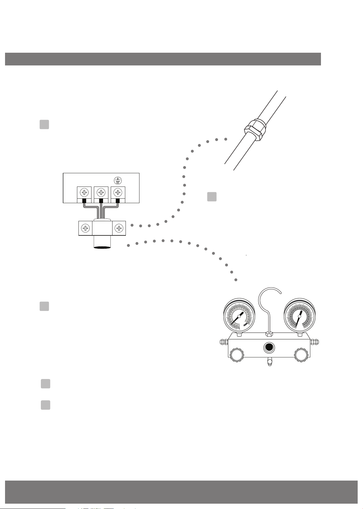
Evacuation Instructions
Before using the manifold gauge or vacuum
pump, read their operation manuals to familiarize
yourself with how to use them properly.
Low-pressure valve
1. Connect the charge hose of the manifold
gauge to the service port on the outdoor unit’s
low-pressure valve.
2. Connect another charge hose from the
manifold gauge to the vacuum pump.
3. Open the low-pressure side of the manifold
gauge. Keep the low-pressure side closed.
4. Turn on the vacuum pump to evacuate the system.
5. Run the vacuum for at least 15 minutes, or until
the compound meter reads -76 cmHG (-1x10⁵ Pa).
6. Close the low-pressure side of the manifold
gauge and turn o the vacuum pump.
7. Wait 5 minutes, then check that there has
been no change in the system pressure.
Manifold gauge
Compound gauge
-76 cmHg
Charge hose
Low-pressure valve
Fig. 9.1
Pressure gauge
High-pressure valve
Charge hose
Vacuum pump
NOTE: If there is no change in the system pressure,
unscrew the cap from the packed valve (highpressure valve). If there is a change in the system
pressure, there may be a gas leak.
8. Insert a hexagonal wrench into the packed valve
(high-pressure valve) and open the valve by
turning the wrench counterclockwise a 1/4 turn.
Listen for gas to exit the system, then
close the valve after 5 seconds.
Flare nut
Cap
alve body
Valve stem
Fig. 9.2
9. Watch the Pressure Gauge for one minute to
make sure that there is no change in pressure.
The pressure gauge should read slightly higher
than atmospheric pressure.
10.Remove the charge hose from the service port.
11. Using a hexagonal wrench, fully open both the
high-pressure and high-pressure valves.
OPEN VALVE STEMS GENTLY
When opening valve stems, turn the hexagonal
wrench until it hits against the stopper. DO NOT
try to force the valve to open further.
12.Tighten the valve caps by hand, then tighten
them using the proper tool.
13.If the outdoor unit uses all vacuum valves,
and the vacuum position is at the main
valve, the system is not connected with the
indoor unit and must be tightened with a
screw nut. Check the gas leakage before
operation to prevent leakage.
Fig. 9.3
Air Evacuation
Page 20
Page 21

Note on Adding Refrigerant
CAUTION
• Refrigerant charging must be performed after wiring, vacuuming, and the leak test.
• DO NOT exceed the maximum allowable quantity of refrigerant or overcharge the system.
Doing so may damage or impact the unit’s function.
• Charging with unsuitable substances may cause explosions or accidents. Ensure that the
appropriate refrigerant is used.
•
Refrigerant containers must be opened slowly. Always use protective gear when charging the system.
• DO NOT mix refrigerant types.
N=2 (one-twin models), N=3 (one-three models), N=4 (one-four models), N=5 (one-ve models).
Some systems require additional charging depending on pipe lengths. The standard pipe length varies
according to local regulations. For example, in North America, the standard pipe length is 7.5 m (25 ft)
In other areas, the standard pipe length is 5 m (16 ft). The additional refrigerant to be charged can be
calculated using the following formula:
ADDITIONAL REFRIGERANT PER PIPE LENGTH
Connective Pipe
Length
Pre-charge pipe length (ft/m)
(standard pipe length x N)
More than (standard
pipe length x N) ft/m
Air Purging
Method
Vacuum pump
Vacuum pump
(Total pipe length - standard pipe length x N) x 15 g/m
(Total pipe length - standard pipe length x N) x 0.16 oZ/ft
Safety And Leakage Check
Electrical safety check
Perform the electric safety check after
completing installation:
1. Insulated resistance
The insulated resistance must be more
than 2 MΩ.
2. Grounding work
Air Evacuation
After nishing the grounding work, measure
the grounding resistance by visual detection
and with a grounding resistance tester. Make
sure the grounding resistance is less than 4 Ω.
3. Electrical leakage check (performed during
test running)
During test operation after installation is
nished, the service man can use the
electroprobe and multimeter to perform
the electrical leakage check. Turn o the
unit immediately if there is leakage.
Look for a solution to the problem until
the unit operates properly.
Additional Refrigerant (
Liquid Side: Ø 6.35 (Ø 1/4”)
Gas leak check
1. Soapy water method:
To check for leakage in the connecting points
of the piping, use a soft brush to apply soapy
water or a liquid neutral detergent to the
indoor or outdoor unit connections. If bubbles
come out, there is leakage.
2. Leak detector
Use the leak detector to check for leakage.
NOTE: The illustration is for explanation purposes
only. The actual order of A, B, C, D and E on the
machine may be slightly dierent from the unit
you purchased. The actual shape shape prevails.
Outdoor unit
check point
R410A:)
N/A
Liquid Side: Ø 9.52 (Ø 3/8”)
(Total pipe length - standard pipe length x N) x 30 g/m
(Total pipe length - standard pipe length x N) x 0.32 oZ/ft
Indoor unit
check point
Page 21
Fig. 9.4
A, B, C, and D are points on a one-four type.
A, B, C, D, and E are points on a one-ve type.
Page 22

Test Run
10
Before Test Run
A test run must be performed after the entire
system has been completely installed. Confirm
the following points before performing the test:
a) The indoor and outdoor units are properly
installed.
b) Piping and wiring are properly connected.
c) No obstacles are near the inlet and outlet of
the unit that might cause poor performance
or product malfunction.
d) The refrigeration system does not leak.
e) The drainage system is unimpeded and
draining to a safe location.
f) The heating insulation is properly installed.
g) The grounding wires are properly connected.
h) The length of the piping and the added
refrigerant stow capacity have been recorded.
i) The power voltage is the correct voltage for
the air conditioner.
F. Check that the drainage system is
unimpeded and draining smoothly.
G. Make sure there is no vibration or
abnormal noise during operation.
5. For the outdoor unit:
A. Check to see if the refrigeration system is
leaking.
B. Make sure there is no vibration or
abnormal noise during operation.
C. Make sure the wind, noise, and water
generated by the unit do not disturb your
neighbors or pose a safety hazard.
NOTE: If the unit malfunctions or does not
operate according to your expectations, please
refer to the Troubleshooting section of the
User's manual before calling customer service.
CAUTION
Failure to perform the test run may result in unit
damage, property damage, or personal injury.
Test Run Instructions
1. Open both the liquid and gas stop valves.
2. Turn on the main power switch and allow the
unit to warm up.
3. Set the air conditioner to COOL mode.
4. For the indoor unit:
A. Ensure the remote control and its buttons
work properly.
B. Ensure the louvers move properly and can
be changed using the remote control.
C. Double check to see if the room
temperature is being registered correctly.
D. Ensure the indicators on the remote control
and the display panel on the indoor unit
work properly.
E. Ensure the manual buttons on the indoor
unit works properly.
Test Run
Page 22
Page 23

Function of Automatic Wiring/Piping Correction
11
Automatic Wiring/Piping Correction Function
The new product is able to automatically correct a wiring/piping error. Press the "check switch" on the
outdoor unit PCB board for 5 seconds until the LED display shows "CE." This means the function is
working. Approximately 5-10 minutes after the switch is pressed, "CE" will disappear, the wiring/piping
error will be corrected, and the wiring/piping will be properly connected.
Check switch
LED display
Correct
Terminal
block
Liquid/
gas pipe
Outdoor unit
Incorrect wiring
B
A
Indoor unit B
B
A
Indoor unit A
Automatic
Correction Function
How to Activate This Function
1. Check that the outside temperature is above 41° F (5° C).
(This fuction does not work when the outside temperature is not above 41° F (5° C))
2. Check that the stop valves on the liquid and gas pipes are open.
3. Turn on the breaker and wait at least 2 minutes.
4. Press the check switch on the outdoor PCB board until the LED display shows "CE."
Outdoor unit
Incorrect wiring
Outdoor unit
Terminal
block
Liquid/
gas pipe
Terminal
block
Liquid/
gas pipe
B
A
Indoor unit B
B
A
Indoor unit A
B
A
Indoor unit B
B
A
Indoor unit A
Page 23
Page 24

The design and specications are subject to change without prior notice for product
improvement. Consult with the sales agency or manufacturer for details.
www.cooperandhunter.us
 Loading...