

Page 1
MULTI
DUCTLESS INVERTER
HEAT PUMP
FLOOR AND CEILING TYPE
INDOOR UNIT
OWNER'S AND
INSTALLATION MANUAL
Models:
CH09UFC230VI
CH12UFC230VI
CH18UFC230VI
CH24UFC230VI
Page 2

User Notice
When installing, the entire capacity of the cooperating indoor unit should be not larger than
◆
150% of outdoor unit, otherwise, it will cause the shortage of cooling (heating) capacity.
The power supply of the entire unit must be the power supply of outdoor unit. And disconnect
◆
the main power of outdoor unit before cleaning.
In order to start up the unit successfully, the main power switch should be opened 8 hours
◆
before the operation.
After receiving the turn off signal, every indoor unit will continue to work for 20-70sec to
◆
make good use of the rest cool air or the rest heat air in the heat exchanger, which will prepare for
the next operation. And this is normal.
When the selected operating mode of the indoor unit is conicted to the operating mode of
◆
the outdoor unit, 5 sec later, the malfunction hint will be shown on the indoor unit or wired controller,
then the indoor unit will stop. At this time, change the operating mode of the indoor unit to the one
that would not conict with the outdoor operating mode to make the operation normal. The HEAT
mode conicts with each of the COOL mode, DRY mode and FAN mode, while the COOL mode,
DRY mode and FAN mode are compatible between each other.
The appliance shall not be installed in the laundry. The appliance shall not be used by
◆
children without supervisor.
Power supply uctuating range (+/-10%, +/-1Hz) .
◆
Humidity range: 30%~95%.
◆
Main switch provided by end user: main switch handle should be black or gray, it can be
◆
locked in “OFF” position with padlock.
The main disconnection device should be installed at a height of 1.97-5.6ft (0.6~1.7m).
◆
Over current protection is required(UL 1995,CSA C22.2).
The cooling range of the unit is the outdoor ambient temp 23-118OF(-5~48
◆
heating range of the unit (only for the heat pump type unit) is the outdoor ambient temp.
5-81OF(-15~27
This appliance is not intended for use by persons (including children) with reduced physical,
◆
sensory or mental capabilities, or lack of experience and knowledge, unless they have been given
supervision or instruction concerning use of the appliance by a person responsible for their safety.
Children should be supervised to ensure that they do not play with the appliance.
℃)
DB.
℃)
DB, the
Thank you for selecting C&H air conditioner. Before use, please read this manual
carefully and keep it properly for furthur reference.
Page 3

Contents
1 Safety Precautions .......................................................................................... 1
2 Installation Precautions and Location Choosing ............................................. 2
2.1 Installation Precautions ......................................................................................... 2
2.2 Location Choosing ................................................................................................ 2
2.3 Imappropriate Location ......................................................................................... 2
3 Installation of Floor and Ceiling Type Indoor Unit ............................................ 3
3.1 Space Dimension for Unit Installation ................................................................... 3
3.2 Important Notice .................................................................................................... 3
3.3 Installation Description .......................................................................................... 3
3.4 Electrical Wiring .................................................................................................... 6
3.5 Drainpipe Installation ............................................................................................ 7
3.6 Install the Connection Pipes ................................................................................. 8
4 Part Names of Floor and Ceiling Type Indoor Unit ........................................ 10
5 Working Temperature Range ......................................................................... 11
6 Maintenance Method ..................................................................................... 12
6.1 Cleaning the Air Filters ........................................................................................ 12
6.2 Cleaning the Unit ................................................................................................ 12
6.3 At the Start of the Season ................................................................................... 12
6.4 During the off Season ......................................................................................... 12
7 Operating Instructions ................................................................................... 13
8 Malfunction Analysis ...................................................................................... 15
8.1 Service Center ..................................................................................................... 15
8.2 After-sales Service ............................................................................................... 16
Page 4
Free Match
1 Safety Precautions
Please read this manual carefully before using this unit. Operate it correctly according to the
guide in this manual.
Please pay special attention to the indicating meaning of these two marks:
Warning! This mark means that the unit may cause property damage, personal injury or
loss of life if the operation is incorrect.
Caution! This mark means that the unit may cause minor or moderate property damage or
personal injury.
Warning!
The unit should be earthed reliably. Do not connect the earth line to the gas pipe, water pipe,
◆
drainage pipe or other unsafe places in potential.
Air conditioner must use special power supply circuit and switches for creepage protect and
◆
air with enough capacity should be installed in the circuit.
Ensure that the connecting of power cord is reliable, otherwise, electric shock or re may
◆
happen.
Do not cut off the power supply when the unit is running, otherwise the lifetime of the unit will
◆
be shortened.
Do not damage wires or use the wires that are not recommended, otherwise, electric shock
◆
or re may happen.
Please don’t operate the unit with wet hands, or electric shock may happen.
◆
Do not put a nger, a rod or other objects into the air outlet or inlet to avoid of damage or
◆
injury.
Cut down the main power supply immediately if any abnormality happens (such as smell of
◆
re etc.). Contact with the service center and consult the qualied technician.
Do not repair or adjust the air conditioner by yourself. Please contact the service center or
◆
Gree technicians for help.
Do not use the fuse with unsuitable capacity or iron thread instead of fuse, otherwise, it will
◆
cause malfunction or re.
Switch off the power supply of the unit before cleaning the air conditioner, otherwise, electric
◆
shock or damage may happen.
Please turn off the main power of the whole unit before cleaning the conditioner, otherwise
◆
electric shock or harm may be happened.
Chemical sprayer should be placed 3.28ft (1m) or more away from the unit,
◆
otherwise fire or explosion may happen.
Do not block air inlets or outlets. Impaired air ow may result in insufcient performance or
◆
trouble.
1
Page 5

2 Installation Precautions and Location Choosing
2.1 Installation Precautions
The installation of air conditioner must be conform to national and local safety
laws.
Installation quality will directly affect the normal use of air conditioner. Do not
attempt to install the air conditioner by yourself. Please contact your dealer after buying
this machine. Professional installation workers will provide installation and test services
according to installation manual.
Do not connect to power until all installation work is completed.
2.2 Location Choosing
Such a place where cool air can be distributed throughout the room.
*
Such a place where condensate water could be easily drained out.
*
Such a place that can handle the weight of indoor unit.
*
Such a place, which is easy for maintenance.
*
Such a place where is easy to get connected with the outdoor unit.
*
Such a place where is 3.28ft (1m) or more away from other electric appliances such as
*
television, audio device, etc.
Avoid a location where there is heat source, high humidity or inammable gas.
*
Do not use the unit in the moist surroundings, such as a laundry, a bath, a shower or a
*
swimming pool.
Be sure that the installation conforms to the installation drawings.
*
2.3 Imappropriate Location
Where there is too much of oil.
*
Where it is acid base area.
*
Where there is irregular electrical supply.
*
Free Match
2
Page 6
Free Match
3 Installation of Floor and Ceiling Type Indoor Unit
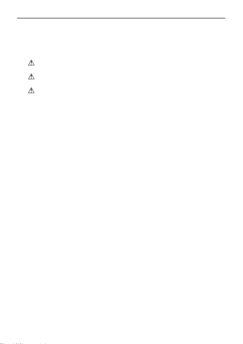
3.1 Space Dimension for Unit Installation
The space around the unit is adequate for ventilation. (Refer to Fig.1)
>59
POWER
RUN
TIMER
>24
>12
>24
>40
>24
>8
>24
>91
>59
>12
Fig.1, distance in inches
3.2 Important Notice
(1). The unit must be installed by the professional personnel according to this install instruction
to ensure the well use.
Please contact the local C&H special nominated repair department before installation. Any
malfunction caused by the unit that is installed by the department that is not special nominated by
Gree would not deal with on time by the inconvenience of the business contact.
(2). It should be done by professional personnel when the air conditioner unit is moved to other
place.
3.3 Installation Description
Ceiling type
*
Floor type
*
These two types of units have similar installing procedure as follows:
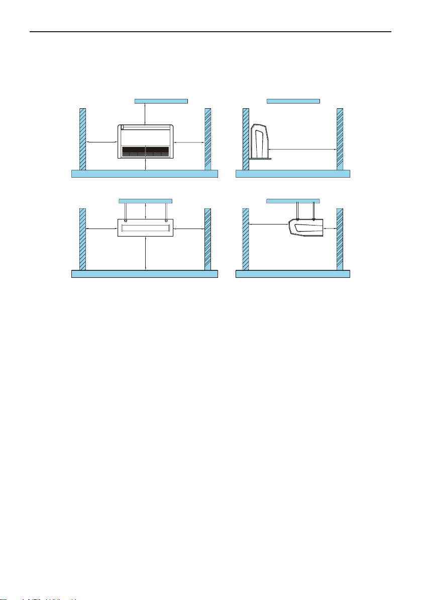
(1). Determine the mounting position on ceiling or wall by using paper pattern to indicate indoor
frame. Mark the pattern and pull out the paper pattern.(Refer to Fig.2)
(2). Remove the return grill, the side panel and the hanger bracket from the indoor unit as per
procedure bellow.
Press the xing knob of the air intake grills, the grilles will be opened wider and then pull
*
them out from the indoor.
Loosen the side panel xing screw and remove the side panel. (Refer to Fig.3)
*
Loosen two hanger bracket setting bolts (M8) on each side for less than 0.39in (10mm).
*
Remove two hanger bracket xing bolts (M6) on the rear side. Detach the hanger bracker by
pulling it backward
3
Page 7
(Refer to Fig.5).
Free Match
Installation
paper plank
Fig.2 Fig.3
(3). Set the suspension bolt. (Use W3/8 or M10 size suspension bolts)
Adjust the distance from the unit to the ceiling slab beforehand. (Refer to Fig.4)
*
(4). Fix the hanger bracket to the suspension bolt.
Warning!
Make sure that extended suspension bolt from the ceiling stays inside the appointed
*
position. Readjust the hanger bracket when it is out of the appointed position. (Refer to Fig.6)
Suspension bolt is xed in the cap of indoor unit. Never remove the cap.
*
(5). Lift the unit and slide forward unit in place. (Refer to Fig.7)
(6). Screw tightly both hanger bracket-setting bolts (M8). (Refer to Fig.5)
(7). Screw tightly both hanger bracket-fixing bolts (M6) to prevent the displacement of the
indoor unit. (Refer to Fig.5)
(8). Adjust the height so that rear side of the drainpipe slightly inclines to improve drainage.
Caution!
Adjust the height by rotating the nut with a spanner.
*
Insert the spanner into the hanger bracket through the interspace. (Refer to Fig.8)
*
In case of hanging
It is possible to install hanger brackets by not removing the brackets from the indoor unit. (Refer
to Fig.9)
Only the specied accessories and parts for installation work could be used.
Side panel fixing screw(M4)
4
Page 8

Free Match
1 3/5” or less
Hanger bracket
Celling
Suspension bolt
Fig.4
Celling slab
Hanger bracket
BOLT POSITION
INWARD
Hanger bracket
Hanger bracket
setting bolt(M8)
Hanger bracket
fixing bolt(M6)
Fig.5
Fig.6 Fig.7
Fig.9Fig.8
When installing the indoor unit, you can refer the paper pattern for installation. Make sure that the
drainage side must be 0.39in (10mm) lower than the other side in order to drain the condensate
water easily.
H
A
C
B
D
Unit: in(mm)
5
Page 9

Model A B H C D
CH09UFC230VI
CH12UFC230VI
CH18UFC230VI
48in
(1220mm)
9in
(225mm)
28in
(700mm)
46in
(1158mm)
(280mm)
CH24UFC230VI
3.4 Electrical Wiring
Caution:
The power of every indoor unit should be connected in outdoor unit.
①.
Open front panel.
②.
Remove the electrical box cover.
③.
Route the power connection cord from the back of the indoor unit and pull it toward the front
through the wiring hole upward.
④.
Put the 4-core cable through the hole of the chassis and the bottom of the appliance
upward, and then connect the power line and the communication line from the outdoor
unit to the corresponding terminals N(1), 2, 3 , and grounding terminal of the indoor unit.
Wiring shall be done properly as per the wiring diagram. (Note: Be sure the wring terminals
A/B/C/D and piping joints A/B/C/D of the indoor unit match with that of the outdoor unit
respectively).
⑤.
Reassemble the electrical box cover.
⑥.
Reinstall the front panel.
Free Match
11in
⑦.
Do not use copper tube at interconnection part as the temperature of refrigerant circuit is
high.
CH36MVCT230VO
INDOOR UNIT D
INDOOR UNIT C
INDOOR UNIT B
INDOOR UNIT A
POWER
N
XT XT XT2
OUTDOOR UNIT
6
L
Page 10

Free Match
CH42MVCT230VO
INDOOR UNIT E
XT6
G
XT5
G
XT4
T CINDOOR UNIT D
OUTDOOR UNI
G
T
XT3
G
INDOOR UNIT AINDOOR UNIT BINDOOR UNI
XT2
G
L
XT1
POWER
N
Caution!
① .
The incorrect of wiring connection would lead malfunction of some of the electric parts.
② .
Be sure to leave some space between the connecting end and the clamp end after the
wiring is xed.
③ .
The installing operation should comform to national wiring regulations.
3.5 Drainpipe Installation
Make sure the drain ows out
(1). Drain piping.
7
Page 11

Free Match
Either the right rear or right side of the unit is suitable for xing the drainpipe.
*
The diameter of the drainpipe should be equal to or greater than that of the connecting pipe.
*
Take the drainpipe as short as possible and slope downward at a gradient of at least 1/100
*
to prevent air pockets.(Refer to Fig.10)
Use the attached drain hose ④and clamp⑤.
*
Insert the drain hose completely into the drain socket. Tighten the clamp within the range of
*
gray tape until the screw head is less than 1/6”(4mm) from the hose. (Refer to Fig.11,Fig.12)
Wrap the attached sealing pad
*
No folding of drain hose inside the indoor unit. (Refer to Fig.13)
*
(2). Conrm that smooth drainage is achieved after the piping work.
Pour 600cc of water into the drain pan from the air outlet for confirming drainage.(Refer to
Fig.14)
(When drain hose is connected)
over the clamp and drain hose to insulate. (Refer to Fig.12)
11
Incling the drain hose
Not to be lifted
No foldings
Not to be
soaking in water
Taping area(Gray)
Clamp⑤
Drain hose④
Fig.10 Fig.11
Cramp⑤
(Accessory)
4mm or less
Large seeing pad⑤
(Accessory)
11
Air outlet
Watering can
Fig.12 Fig.13 Fig.14
3.6 Install the Connection Pipes
8
Page 12

Free Match
PipePipe Flare Nut
Spanner
Nut-Required Torque
Pipe Diameter (mm) Required Torque
φ6.35 15--30
φ9.52 35-40
φ12 45-50
φ15.9 60-65
(1). Align the ared end of the copper tube with the threaded connector, and then hand-tighten
the ared nut.
(2). Further tighten the ared nut with a torque wrench until the torque wrench sounds a “crack”.
(3). The bending of the pipe shall not be too small, otherwise the pipe may crack. A pipe bender
must be used when bending the pipe.
(4). Wrap the thermally untreated pipe and connectors with sponge and then tighten the sponge
with plastic tape.
Notes:
① .
During the piping, do not pull any connector forcefully to prevent the capillary and other
pipes from cracking, which then would result in leakage.
② .
The pipe should be properly supported in the way that its weight will not be borne by the
unit.
If the specication of the outdoor unit pipe joint does not conform to that of the indoor unit, then
the joint specication of the outlet pipe of the indoor unit takes precedence. A reducing nipple shall
be installed at the joint of the outdoor unit so as to make the joint of the outdoor unit compatible
with that of the indoor unit.
9
Page 13

Free Match
4 Part Names of Floor and Ceiling Type Indoor Unit
Air outlet
Guide louver
Front panel
Air filter, purifier
Suitable model
(in air inlet grille)
:
Air inlet
CH09UFC230VI
CH12UFC230VI
CH18UFC230VI
CH24UFC230VI
Note: Different models of air conditioners as shown above have the same appearances.
Connecting
pipe
10
Page 14

Free Match
5 Working Temperature Range
Working Temperature Range
Indoor side state
Dry bulb
temp.
℉(℃)
Rated. Cooling 80.0(26.7) 67.0(19.4) 95.0(35.0) 75.0(23.9)
Max. cooling 80.0(26.7) 67.0(19.4)
Min. cooling 67.0(19.4)
Rated. Heating
Max. heating 80.0(26.7) — 75.0(23.9)
Low Ambient heating
70
.0(21.1)
70
.0(21.1)
℉(℃)
Wet bulb
temp.
℉(℃)
57
.0(13.9) 67.0(19.4)
60
.0(15.6)
60
.0(15.6)
temp.
Outdoor side state
Dry bulb
℉(℃)
115
.0(46.1) 75.0(23.9)
47
.0(8.3)
5
.0(-15.0)
Wet bulb
temp.
57
43
65
3.2(-16.0
℉(℃)
℉(℃)
.0(13.9)
.0(6.1)
.0(18.3)
)
11
Page 15

Free Match
6 Maintenance Method
Warning!
① .
Turn off the unit and cut off the power supply when cleaning the air conditioner, otherwise,
electric shock may happen.
② .
Do not let the air conditioner get wet, or it will cause electric shock. Ensure that the air
conditioner will not be cleaned by water rinse under any circumstances.
③ .
Volatile liquid like thinner or gasoline would damage the appearance of air conditioner.
(Note: Only soft cloth and wet cloth that moistened by neutral cleaning uid could be used to clean
the front panel of air conditioner.)
6.1 Cleaning the Air Filters
Warning!
Air lters should be cleaned by professionals with proper operation to ensure personal
safety.
Suggestion:
If the air filter is dirty, it will
influence normal airflow. As a result,
the unit will be overloaded and
consume 6% additional electric energy.
So regular cleaning is necessary.
6.2 Cleaning the Unit
Clean the air conditioner and the remote control with dry cloth or a vacuum cleaner. If damp
cloth is used, remove moisture by using dry cloth afterward.
Caution
① .
gasoline, thinners or polishing products for
cleaning.
② .
104oF(40
be deformed.
!
Do not use benzine solvent,
Do not wash with hot water (above
). Some parts of the unit may
℃
6.3 At the Start of the Season
Check if there is blockage at inlet and outlet of the air conditioner.
*
Check if the batteries in wireless remote controller has been exchanged.
*
Check if the batteries in wireless remote controller had been exchanged.
*
Check if the air lter has been installed well by professionals.
*
In order to start up the air conditioner smoothly after long period stop, switch on the main
*
power supply 8 hours before turning on the air conditioner.
Notice: All the operations above should be operated by professionals.
*
6.4 During the off Season
Switch off the main power supply.
*
Clean the air lters and other parts by professionals.
*
Keep the fan running for 2-3 hours to dry out the inside of the unit.
*
Notice: All the operations above should be operated by professionals.
*
12
Page 16

Free Match
7 Operating Instructions
The expected temperature should
*
be set at a moderate level to avoid of
unnecessary energy consumption.
Airflow direction will be changed by
*
adjusting the louvers and flaps as shown,
accordingly well air condition the room
temperature.
Clean the air filter every week for
*
higher efciency by professional.
Cover windows with a blind or a curtain
*
to prevent heat source from sunlight when
the unit is cooling, which helps to reduce
energy consumption.
Close the window and door while operating
*
the unit for saving energy.
In case of ineffective ventilation,
*
open the window to ventilate room air
occasionally, meanwhile, close the window
timely for saving energy.
13
Page 17

Check electrical system (voltage and
*
frequency). Use the power supply indicated
on the nameplate of the unit to operate the
air conditioner and only fuses with specied
capacity should be done by technicians. Do
not use pieces of wire instead of fuse.
Do not insert objects into the air inlet or
*
outlet when the air conditioner is running
as it may cause damage or personal injury.
Also pay special attention when children
are around.
Free Match
If electric shock suddenly happens, turn
*
off the unit. If the unit is not to be used
for a long period, cut off the main power
supply.
Do not place any obstacles around
*
the indoor and outdoor unit to avoid of
inefcient performance or malfunction.
*
Never expose infants, aged persons or
patients directly to the air ow.
Do not locate a heater or any other
*
heat source close to the unit. The heat
may deform plastic parts.
14
Page 18

Free Match
8 Malfunction Analysis
Warning!
Repairing work should be done by Gree technicians. For saving your time and spending,
please check the following malfunction analysis before contacting customer service center.
Malfunction Phenomena Malfunction Analysis
After turning off the air
conditioner, the unit could not
restart immediately.
Odor gives out when the unit
just turns on.
Slight noise is heard when the
unit is running.
There is mist coming from air
outlet under cooling mode.
Creak sound is heard when the
unit is running or shut down.
The air conditioner could not
run.
The cooling (heating) effect of
the air conditioner is not good.
Wireless remote controller
doesn't work.
The overload protection switch of the unit needs 3 mins before
restarting.
When air conditioning, odor or smoke that was sucked in is
discharged again.
The refrigerant ows in the liquid pipe will make some noise.
Indoor temperature declines too fast.
When the ambient temperature changes, the panel and other
parts expand or shrink, which might cause some grating sound.
Whether the unit is powered off.
Whether the unit is disconnected with power supply.
Whether the circuit breaker trips off.
Whether the voltage is too high or too low.
Whether the TIMER has been set in the wireless remote
controller.
Notice: All the operations above should be done by Gree
technicians.
Wether the temperature is set properly.
Whether the inlet or outlet of the unit is blocked.
Whether the air lter is too dirty to cause blockage.
Whether the windows and doors are closed.
Whether the airow volume is set at low speed.
Whether there is any heat source in the room.
If the wireless remote controller doesn't work with new
batteraries, remove the back cover and press ”ACL” button to
make it normal.
The air conditioner is under abnormal disturbance orchanging
function too frequently, to make wireless remote controller cannot
control. Cut off main power supply and re-electrify could resume
normal operation.
Whether the controller is within the signal receiving area;
Whether there is blockage;
Check if the batteries in wireless remote controller are worn out,
otherwise change the batteries.
8.1 Service Center
When the following phenomena appears, please stop operating immediately, cut off the power
supply and contact service center for help.
Harsh sound is heard when the unit is running.
*
When the fuse melts or the circuit breaker trips off frequently.
*
When some objects or water is sucked in the unit accidently.
*
15
Page 19

When there is water leakage from indoor unit.
*
When the power cord is overheating.
*
Odor gives out when the unit is running.
*
8.2 After-sales Service
Please contact the dealer if the air conditioner has any quality problems.
Free Match
16
Page 20

www.cooperandhunter.us
LIMITED WARRANTY STATEMENT
Ductless Heat Pump Multi-Split System
This warranty should be registered on our web-site www.cooperandhunter.us
The warranty is only valid when installed by a Licensed HVAC Technician
FOR WARRANTY SERVICE OR REPAIR:
Contact your installing contractor. You may find the installer’s name on the equipment or in your Owner’s packet.
Complete product registration below and send back by e-mail at
PRODUCT REGISTRATION:
Model No.: ______________________________________________________________________________________________
Serial No.: _________________________________________ ______________ Date of Installation: ______________________
Owner Name: ____________________________________________________________________________________________
Address of Installation:_____________________________________________________________________________________
Installing Contractor: ___________________________ _______________________________________________
Address: ________________________________________________________________________________________
Phone No. / E-mail: _______________________________________________________________________________
____________
C&H distributor (hereinafter “Company”) warrants this product against failure due to defect in materials or workmanship
under normal use and maintenance as follows. All warranty periods begin on the date of original installation. If the date cannot
be verified, the warranty period begins one hundred twenty (120) days from date of manufacture.
failure to use, install or maintain the product in a manner consistent with our/manufacturer’s recommendations shall render the
warranty void. Cooper&Hunter, at its option, may request a report from a qualified technician prior to honoring a warranty
claim.
If a part fails due to defect during the applicable warranty period Company will provide a new or remanufactured part, at
Company’s option, to replace the failed defective part at no charge for the part. This limited warranty is subject to all
provisions, conditions, limitations and exclusions listed below.
● A warranty period of Seven (7) years on compressor to the original registered end-user.
● A warranty period of Five (5) years on all parts to the original registered end user.
● A warranty period of One (1) year on the remote control provided with the original unit.
● Limited warranty applies only to systems that are properly installed by a state
contractor,
under applicable local and state law in accordance with all applicable building codes and permits; C&H installation
and operation instructions and good trade practices.
● Warranty applies only to products remaining in their original installation location.
● Defective parts must be returned to the distributor through a registered servicing dealer for credit.
Damage resulting from
certified or licensed HVAC
Page 21

LIMITATIONS OF WARRANTIES:
CONDITIONS OF MERCHANTABILITY AND FITNESS FOR A PARTICULAR USE OR PURPOSE) ARE LIMITED TO THE DURATION OF
THIS LIMITED WARRANTY, SOME STATES OR PROVINCES DO NOT ALLOW LIMITATIONS ON HOW LONG AN IMPLIED WARRANTY
OR CONDITION LASTS, SO THE ABOVE MAY NOT APPLY TO YOU. THE EXPRESS WARRANTIES MADE IN THIS WARRANTY ARE
EXCLUSIVE AND MAY NOT BE ALTERED, ENLARGED, OR CHANGED BY ANY DISTRIB
WHATSOEVER.
ALL IMPLIED WARRANTIES AND/OR CONDITIONS (INCLUDING IMPLIED WARRANTIES OR
UTOR, DEALER, OR OTHER PERSON,
THIS WARRANTY DOES NOT COVER
1. Labor or other costs incurred for diagnosing, repairing, removing, installing, shipping, servicing or handling of either
defective parts, or replacement parts, or new units.
2. Product cleaning required prior to warranty service and repair.
3. Normal maintenance as outlined in the installation and servicing instructions or Owner’s Manual, including filter
cleaning and/or replacement and lubrication.
4. Failure, damage or repairs due to faulty installation, misapplication, abuse, improper servicing, unauthorized
alteration or improper operation.
5. Failure to start due to voltage conditions, blown fuses, open circuit breakers, or damages due to the inadequacy or
interruption of electrical service.
6. Failure or damage due to floods, winds, fires, lightning, accidents, corrosive environments (rust, etc.) or other
conditions beyond the control of the Company.
7. Failure or damage of coils or piping due to corrosion on installations within one (1) miles of sea coast or corrosive
body.
8. Parts not supplied or designated by Company, or damages resulting from their use.
9. Products installed outside continental USA and Canada.
10. Electricity or fuel costs, or increases in electricity or fuel costs from any reason whatsoever, including additional or
unusual use of supplemental electric heat.
11. Any cost to replace, refill or dispose of refrigerant, including the cost of refrigerant.
12. Shipping damage or damage as a result of transporting th
13. Accessories such as condensate pumps, line sets and so forth are not covered.
14. Any special, indirect or consequential property or commercial damage of any nature whatsoever. Some states or
provinces do not allow the exclusion of incidental or consequential damages, so the above limitation may not apply to
you.
This warranty gives you specific legal rights, and you may also have other rights which vary from state to state or province to
province.
:
e unit.
66179425
 Loading...