

Cooper&Hunter CH09SPH115V, CH18SPH230V, CH24SPH230V, CHS30FTXWSV, CH12SPH115V Troubleshooting Guide
...Page 1

SOPHIA
SPLIT AIR CONDITIONER
WITH HEAT PUMP
TROUBLESHOOTING
Page 2

1.1 Indoor Unit Error Display
Operation
lamp
Indoor room temperature sensor T1 open circuit or
short circuit
Evaporator coil temperature sensor T2 open circuit or
short circuit
O
F0
Outdoor ambient temp erature sensor T4 open circuit or
short circuit
Condenser coil temperature sensor T3 open circuit or
short circuit
Compressor discharge t emp er at ur e sensor TP open
circuit or short circuit
High temperature protection of IPM module or
compressor top
7 times
P6
Low pressure protection(Only for 36K)
Timer lamp Display LED STATUS
☆ 1 time
☆ 2 times
☆ 3 times
☆ 4 times
☆ 5 times
☆ 6 times
☆ 7 times
☆ 1 times
☆ 2 times
☆ 3 times
☆ 4 times
☆ 5 times
☆ 6 times
☆ 1 times ☆
X E0 Indoor unit EEPROM parameter er r or
X E1 Indoor / outdoor units com mu nication error
X E2 Zero-crossing signal detection error
X E3 Indoor fan speed has been out of cont rol
X E4
X E5
X EC Refrigerant leakage detection
O F1
O F2
O F3
O F4 Outdoor unit EEPROM parameter error
O F5 Outdoor fan speed has been out of contr ol
Overload current protect io n
P0 IPM malfunction or IG BT over-strong current protection
☆ 2 times ☆
☆ 3 times ☆
☆ 4 times ☆
☆ 5 times ☆
☆ 6 times ☆
☆
*P3
1) In heating mode, when the outdoor temperature is lower than -25℃ for 1 hour, the indoor unit
display error code P3.
2) If the outdoor temperature is higher than -22℃ for 10 minutes and compressor stop for 1 hour or
outdoor temperature is hi gher than -5℃ for 10 minutes, then the unit will return to work.
* Fault Symptom: The display board shows a garbled code or a code that is not an error code found
in the service manual nor a t emp er at ur e r eading.
Trouble shooting:
Use the remote controller. If the unit does not respond to t he r em ot e, the indoor PCB needs to be
replaced; if the unit does respond, then the display board needs to be replaced
☆
O(light) X(off) ☆(flash)
P1 Over voltage or over low voltage protection
P2
P3* Outdoor ambient temperature too low.
P4 Inverter compressor drive error
P5 Indoor units mode conflict (multi-zone ONLY)
Page 3
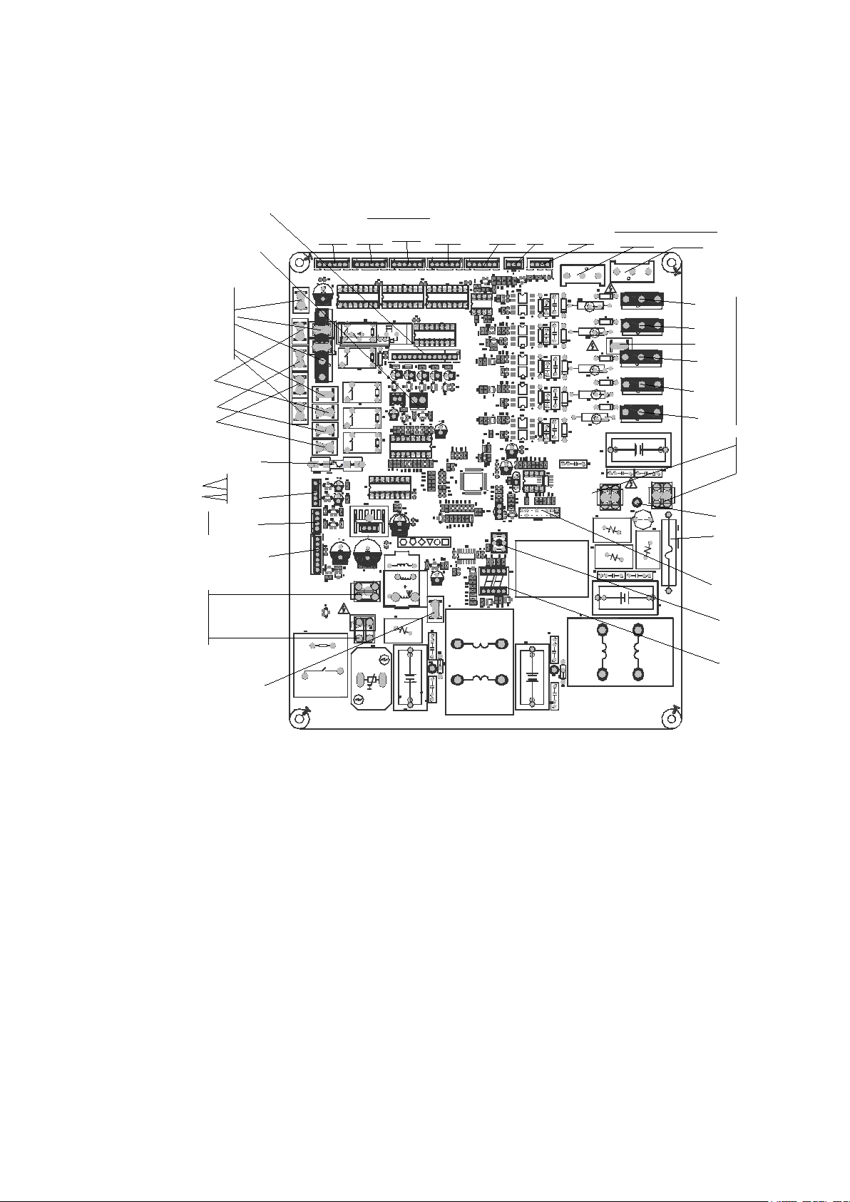
1.2 Outdoor unit error display(TBD)
N
1
17122000019195
1
1
[ 1. 6 ] 20 15-09- 30
US- KFR-35W/BP3N1- (115V+RX62T+41560) .D. 13.WP2- 1
L- IN N- I N
7805
S
HEAT1
4 - WA Y
AC- FAN
HEAT2
Ear t h
DC- F AN
PMV
TESTPORT
BLACK
W
RED
V
BL UE
U
CN4_ 1
CN4_ 2
CN4_ 3CN4 _4
REA CT OR
CAP
T3T4
TP
N
N
N
H
L
CN25
CN31
AC
AC
+
-
BR1
+
E2
CN21
RC1
E304
ZR2
+
-
AC
OUT
IN
~~
RY3A
SJ-S- 112DMG
R191
I C105
CN15
ZR5
ZR4
R628
C618
R118
R123
R122
C324
I C2
R421
R621
D103
C413
C306
C319
I PM301
R176
R175
+
E109
C107
T401
R410
R409
R316
3W-10m¦ ¸¡ À1%
D407
+
+
C110
R623
R602
C624
RY3
R196
D610
C318
C316
C314
C134
+
E605
E303
E208
E206
E302
E300
CN50
R523
R522
R521
R520
R519
R518
R517
R323
R322
R321
R320
R319
R318
R317
I C301
C513
C512
C511
C323
C321
C320
R426
R314
R306
R305
R304
R303
C311
C310
C309
C308
C307
CN28
CN29
CN30
C520
C1
+
E106
C101
D101
C611
R171
D602
I C102
Rdi
D404
D401
CN6
ZR1
RY2
R626
R620
R619
R618
R617
R616
R615
R612
R611
R610
R608
R607
R605
R603
R601
R528
R516
R513
R508
R506
R504
R502
R429
R428
R427
R408
R407
R406
R405
R404
R403
R315
R301
R190
R188
R187
R186
R185
R182
R181
R180
R179
R178
R174
R173
R170
R169
R168
R165
R157
R155
R154
R152
R150
R149
R148
R147
R144
R143
R142
R140
R138
R137
R136
R135
R133
R132
R131
R130
R129
R128
R127
R126
R125
R124
R121
R120
R117
R116
R115
R114
R112
R111
R110
R108
R107
R106
R105
R102
R101
R2
Q101
OSC101
NTC2
+
LED101
I C603
I C602
I C601
I C403
I C401
I C1
+
E602
+
E401
+
E108
+
E107
+
E105
+
E103
+
E102
+
E101
+
E1
+
E3
+
DZ601
DZ304
DZ303
DZ302
DZ301
+
DZ203
+
DZ202
D406
D402
+
D2
+
D1
1
CN50 5
CN7
C615
C614
C612
C606
C605
C601
C509
C508
C507
C506
C505
C504
C503
C412
C410
C409
C408
C405
C404
C403
C402
C401
C322
C312
C305
C303
C302
C274
C273
C272
C271
C133
C132
C131
C130
C129
C128
C127
C126
C125
C124
C123
C121
C120
C119
C118
C116
C115
C114
C113
C112
C111
C106
C105
C104
C103
C102
C16
C11
C10
C7
C6
C5
C4
C3
C2
+
E280
+
E281
+
E282
+
E283
+
E404
+
E407
PTC1
+
E409
D104
R401
R103
C117
R195
R172
+
DZ204
C275
R156
R604
R104
I C101
I C104
RY4
+
E410
+
E405
FUSE1
T20A/25 0VAC
C9A
CN1A
I C404
+
D403
I C103
C613
CN3
CN2
CN1
CN16
+
DZ201
L2L3L4L5
C135
CN17
R21 R23
R158
RY5
21
4
3
3
4
ON
1 2
ON
S W2
RC2
DSA1
I C405
+
CN60
C8
L1
R1
I PM501
C122
Comment
Comment
RY1
CN50 7
R606
3W-10m¦ ¸¡ À1%
R25 3
0. 75¦ ¸/ 1W
R25 4
0. 75¦ ¸/ 1W
connect to compressor heater
when is on, 100-130V AC outpu
connect to 4-way Valve
when is on, 100-130VAC OUTPUT
connect to PFC Capacitor
when is on, 100-130V AC
output
connect to reactor
when is on, 100-130V AC output
connect to
Ground
connect to N-line
(100-130VAC INPUT)
connect to L-line
(100-130VAC INPUT)
connect to indoor unit
communication
U
V
W
10- 230VAC¡ ¯ (r unn i n g)
0VAC (st andby)
conne ct t o DC Mot or
external driver motor
connect to Electric Expansi
pipe temp.sensor& room temp.
sensor&Exaust temp. sensor
6 5 4 3
TP T4
RT
RT
+5VDC
+5VDC
+12V DC pulse wave bet ween ( +1) -G
+12V DC pulse wave bet ween ( +2) -G
+12V DC pulse wave bet ween ( +3) -G
+12V DC pulse wave bet ween ( +4) -G
+12 V DC
+12 V DC
6 5 4 3 2 1
AC fan motor
5
4
3
2
1
low speed
N line
high speed
FAN Starting Capacitor
FAN Starting Capacitor
connect to chassis heater
when is on, 100-130VAC OUTPUT
UV
W
0VAC(standby)
10- 230VAC¡ ¯( runni ng)
connect to
compressor
connect to PC
communication
EEPROM Programmer
Port
Test Port
bridge
IPM for compressor
IPM for DC FAN
P
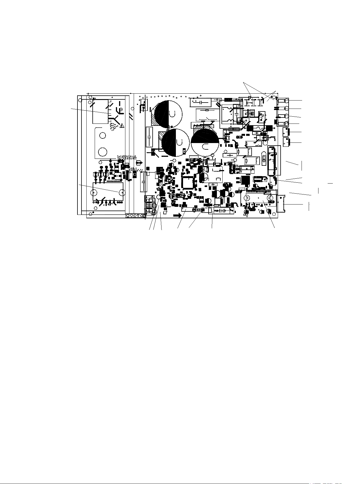
For CH-09SPH-115VO, CH-12SPH-115VO, CH-09SPH-230VO, CH-12SPH-230VO
,
Page 4
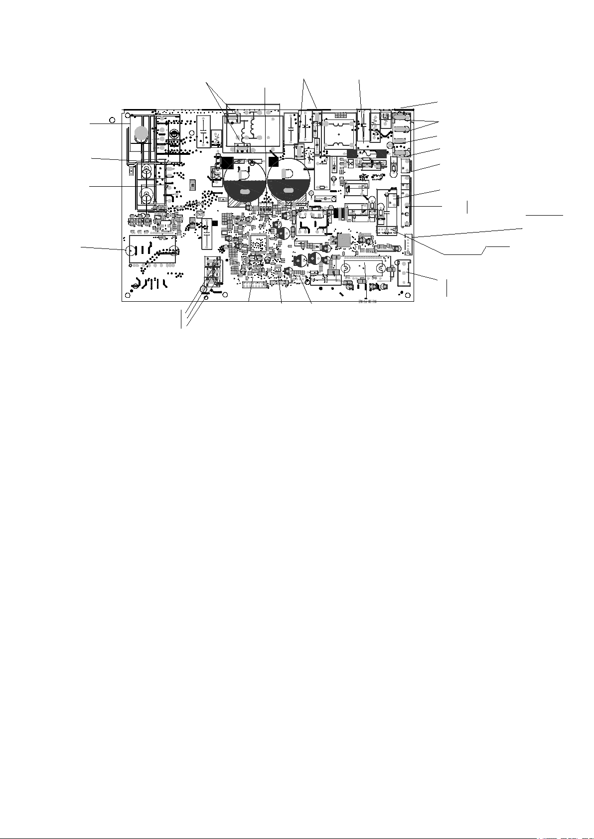
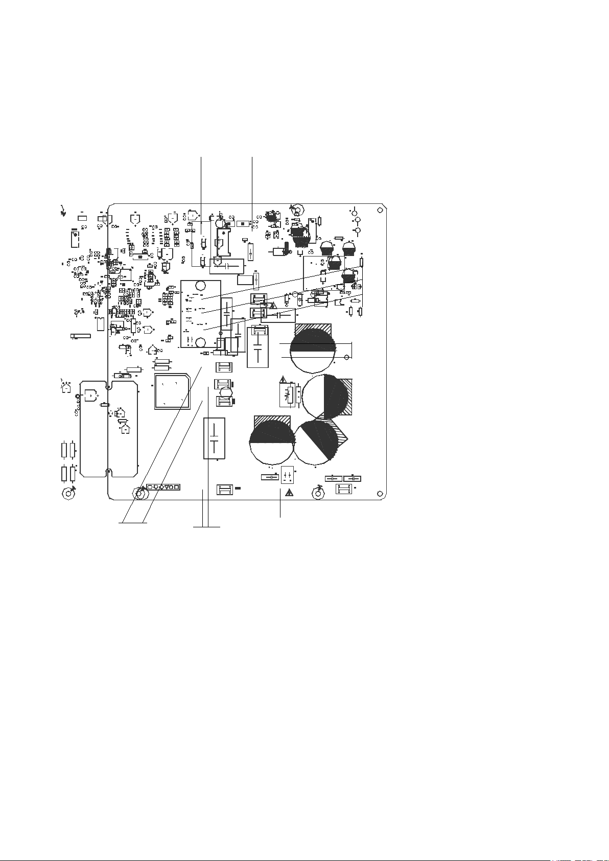
For CH-09SPH-230VO, CH-12SPH-230VO, CH-18SPH-230VO, CH-18SPH-230VO
+
T4
TP
T3
N
L
H
N
N
Rdi
Hav e
Low-Fre
YES
NO
No
U
BLUE
V
RED
W
BLACK
TESTPORT
PMV
DC- FAN
DR_L
DR_N
Ear t h
HEAT2
AC- FAN
4 - WA Y
HEAT1
S
7805
N- I N
L- IN
KFR- 35W/ BP3N1-( RX62T+41560) .D.13. WP2-1
[ 1. 8] 2015- 12- 31
1
1
17122000002718
1
E304
E208
C10
RC3
CN22
ZR4
R696
R69 5
C696
C69 5
ZR5
C9
IPM501
L1
C8
CN60
+
IC405
DAS1
RC2
ON
2
1
ON
4
3
3
4
1
2
SW2
RY5
R158
R23
R21
CN17
CN11
CN10
C135
L5
L4
L3
L2
+
DZ201
L601
CN16
CN1
CN2
CN3
CN3_ 1
C613
IC103
CN50 7
+
D403
IC404
CN1A
FUSE1
T20A/250VAC
E405
E410
RY4
IC104
IC101
R104
R604
R156
C275
DZ204
R172
R195
C117
R103
R40 1
D104
E409
PTC1
CN32
BR1
E407
E404
E283
+
E282
+
E281
+
E280
RY1
D601
Q601
C2
C3
C4
C5
C6
C7
C11
C16
C102
C103
C104
C105
C106
C111
C112
C113
C114
C115
C116
C118
C119
C120
C121
C123
C124
C125
C126
C127
C128
C129
C130
C131
C132
C133
C271
C272
C273
C274
C302
C303
C305
C312
C322
C40 1
C402
C403
C404
C405
C408
C409
C410
C503
C504
C505
C506
C507
C508
C509
C601
C605
C606
C612
C614
C615
CN7
CN9
CN31
CN50 5
D1
D2
D402
D406
DZ202
DZ203
DZ301
DZ302
DZ303
DZ304
DZ601
E1
E2
E101
E102
E103
E105
E107
E108
E401
E602
IC1
I C40 1
IC403
IC601
IC602
IC603
LED101
NTC2
OSC101
Q101
R2
R3
R101
R102
R105
R106
R107
R108
R110
R111
R112
R114
R115
R116
R117
R120
R121
R124
R125
R126
R127
R128
R129
R130
R131
R132
R133
R135
R136
R137
R138
R140
R142
R143
R144
R147
R148
R149
R150
R152
R154
R155
R157
R165
R168
R169
R170
R173
R174
R178
R179
R180
R181
R182
R185
R186
R187
R188
R189
R190
R301
R315
R403
R404
R405
R406
R407
R408
R427
R428
R429
R502
R504
R506
R508
R513
R516
R528
R601
R603
R605
R607
R608
R610
R611
R612
R615
R616
R617
R618
R619
R620
R626
RY2
ZR1
CN6
D40 1
D404
Rdi
IC102
D602
R171
C611
D101
C101
E106
C1
C52 0
ZR3
CN30
CN29
CN28
C307
C308
C309
C310
C311
R303
R304
R305
R306
R314
R426
C320
C321
C323
C511
C512
C513
IC301
R317
R318
R319
R320
R321
R322
R323
R517
R518
R519
R520
R521
R522
R523
CN50
E206
E605
C134
C314
C316
C318
CN25
D610
R196
RY3
C624
R602
R623
C110
C122
D407
R316
3W- 10m| ??¨¤1%
R409
R41 0
R606
3W- 10m1%
T401
C107
E109
R175
R176
I PM301
C319
C306
C413
D103
R621
R421
IC2
C324
R122
R123
R118
C618
R628
CN15
I C105
R191
RY3A
ZR2
RC1
CN21
R1
C41 2
E300
E302
E303
C33 0
C33 1
C33 2
C33 3
C33 4
connect t o t he t er mi nal
208-230V AC
power suppl y
connect to earth
CN60
connect to 4-way valve
when 4-way i s ON, out put 208- 230VAC
connect t o c ompr ess or heat er
power suppl y
CN17
AC fan motor
L low speed
N ground
H high speed
CN21/CN22
exhaust temp. sensor& pipe
temp.sensor& room temp.
sensor
6 5 4 3 2 1
TP T4 T3
RT
RT
+5VDC
RT
+5VDC
+5VDC
connect to Electric Expansion Valve
+12V DC pul se wave bet ween (+1) - GND
+12V DC pul se wave bet ween (+2) - GND
+12V DC pul se wave bet ween (+3) - GND
+12V DC pul se wave bet ween (+4) - GND
+1 2 V DC
+1 2 V DC
6 5 4 3 2 1
connect to indoor unit communication
HEAT2
connect to chassis heater
when is on, 208-230VAC OUTPUT
U
V
W
10- 200VAC¡ ¯ (r unni ng)
0VAC ( st andby)
connect t o t he DC compressor
Test Port
Connect to PC
communication
EEPROM Programmer Port
FUSE1 20A/250VAC
U
V
W
10-200VAC¡ ¯ ( r unni ng)
0VAC ( st andby)
connect t o DC Mot or
External driver motor
slow flicker:standby(
0.5Hz
)
quick flicker:error(
2Hz
)
continuous light: normally running
Connect to reactor
IPM for
compressor
IGBT
FRD
when heater is ON, output 208-230V AC
BR
P
N
Page 5
Sucti on
Exhaust
+
17122200000309
Hui Qi
Tes tPort
1
1
HEAT
4 - WA Y
W
BL UE
BLACK
RED
V
U
TPT3T4
No
NO
NO
YES
Low-Fre
No
Have
YES
Have
Temp-Pro
Rdi
Ri pm
11
PMV
44
15V17V
[V1. 8] 2015- 01- 16
7815
22
1
34
REACT OR
311 TEST
7805
N- I N
DC- F AN
AC- FAN
L- I N
S
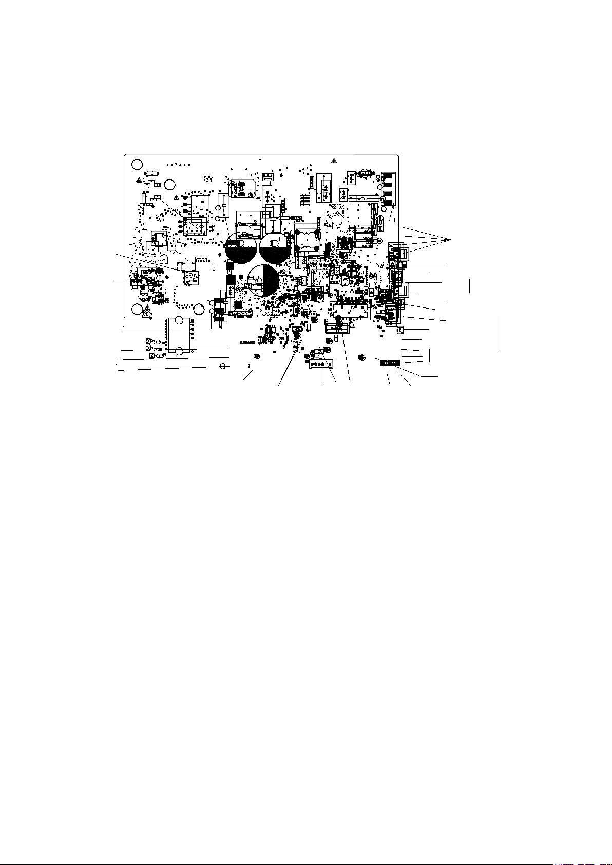
KFR-72W/ BP2- (311+0515+6061HD+PSS30S92F6-AG+6822+HEAT). D. 13.WP2.1
12V 5V
CN3
DSA1
K
A
K
D5
R18
R46
R107A
R515A
R316A
R18A
IC4 03
D4
C21
R54
R55
R68
R69
R56
R90
C14
J4
R16
R52
J5
+
LED1
R78
R142
R141
R155
R154
R153
R152
R151
R150
C3
R108
R107
RC2
RC4
RC1
RC3
C1
FUSE1
65T 250V30A
ZR1
ZR2
CN30
R109
R58
R61
R60
R59
C301
C76
C312
R315
C83
C85
C86
C91
R156
R158
R169
R170
R171
R172
IC34
D11
R157
R159
C310
C306
C308
C311
C307
C309
R110
E305
C302
+
DZ301
Q3
R75
R84
C103
CN28
CN29
CN6- 1
CN6
CN13
CN12
CN2
CN8
CN7
CN22
DR
CN21
DR
R102
J6
PTC1
CN41 4
R127
C105
+
E5
I PM2
C501
C503
C507
C508
C509
C510
C511
C512
C517
+
DZ501
R501
R502
R503
R504
R505
R506
R509
R510
R511
R512
R513
R514
R523
C502
C505
+
DZ502
R515
R522
+
DZ504
C504
R316
~ ~
IN
AC
+
R101
R100
R71
C42
CN20
RY5
CN16
CN18
NTC4
C8
C513
C514
C515
C516
R516
R517
R518
R519
R520
R521
C27
IC7
24LC512
33
49
17
1
IC9
R53
IC1 01
R160
+
E4
+
E3
R83
R82
R81
R80
R79
R50
C47
C20
R322
R321
R320
Q2
IC4 05
+
E10
R120
R167
R166
R32
+
E1
R12
+
LED3
R412
R413
R414
R415
Rdi
Ri pm
R13
CN24
R72
R8
R87
R74
J3
IC17
+
E24
D2
R124
C2
J2
J1
C77
AC AC
+
-
BR1
C13
D3
R7
RY3
RY4
RY2
CN5
R23
R24
R25
R26
R27
C74
C75
RY1
+
E14
C9
C17
C18
C19
C23
C24
C26
C32
C33
C35
C36
C37
C39
C43
C48
C49
C52
C65
C67
C78
C87
C89
C90
C92
C147
C153
C25
CN9
CN23
CN39
+
E17
+
E23
+
E28
IC8
24LC08
IC12
24LC08
IC14
+
LED2
OSC1
R5
R30
R31
R40
R41
R42
R48
R49
R62
R64
R65
R66
R70
R73
R76
R77
R86
R92
R97
R161
R162
R163
R164
R165
R176
R177
R419
X1
C58
+
+
E405
IC4 04
R45
Q1
C15
C22
R21
R22
R28
R29
R33
+
E22
R3
R4
R121
C5
+
E6
R10
C28
C4
CN38
IC10
C79
C80
D7
C6
R148
R63
C506
R507
R508
+
E11
R106
C73
IC21
PC817
IC31
PC817
R175
R178
C409
IC4 02
C403
IC11
+
E402
D401
C401
R403
C411
C40
C50
D403
R401
R405
R406
R404
+
E404
D402
D404
C408
C402
+
E403
R407
R408
C404
C110
+
E409
+
E401
R402
C405
10
9
7
6
5
4
3
1
T401
C406
C407
D13
D14
+
E406
+
E407
+
E408
+
E502
+
E503
+
E504
+
DZ503
CN25
R6
R9
CN60
IC4 06
IC4 07
C7
D1
R1
R137
IC2
PC851
IC1
PC817
R2
R126
R125
R123
R122
R119
R118
R117
R15
R14
C99
C98
C97
C96
C95
C94
C93
C66
D20
R17
CN17
CN10
CN1
C41
R38
C45
C44
R136
R135
R134
R104
D12
D10
C54
+
D8
D9
R57
R20
C242
C243
C244
R89
E2
R67
C84
C10
C11
IC4
C12
C38
R34
R47
R88
IC32
R39
R35
R36
R19
+
DZ6
R37
C46
C51
C53
CN19
+
DZ2
+
E27
IC3
PC817
IC5
PC817
Q8
R43
R44
R85
R91
R93
R95
R96
R99
D15
R51
+
E410
+
E8
C60
C61
E302
E303
E304
C62
VN1
VP1
U
P
VUB
U+
W
V+
V
W+
U-
VVB
VWB
FO
W-
V-
NV
NW
NU
VNC
CIN
I P M1
+
DZ304
+
DZ303
+
DZ302
C314
C316
C318
C30
C34
C31
ZR3
ZR4
C82
L1
R11
R140
CN27
E301
R168
I GBT 1
connect to the DR module
connect to earth
fuse 250V 30A
connect to reactance
290-330VDC standby
210-300VDC running
power supply 208-230V AC connect to the terminal
connect to 4-way val ve
when 4-way is on, output 208-230V AC
AC FAN mot otr
connect to co mpressor heater
when heater is on, output 208-230V AC
1 low speed
2 hign speed
3 ground
external drive mo tor
connect to DC motor
0V AC st andby
10~200V AC
’
running
U
V
W
connect to electric expansion valve
6 5 4 3 2 1
+
12VDC
+
12VDC
+12V DC pulse wave between( +4)-GND
+12V DC pulse wave between( +3)-GND
+12V DC pulse wave between( +2)-GND
+12V DC pulse wave between( +1)-GND
EEPROM Programmer Port
reserve
test port
Connect to PC
communication
V
U
W
connect to PC communication
test port
LED: status light
(
yellow
)
CN5
/CN4 connect to
chassis
heater
when heater is on, ou tput 208-230V AC
connect to DC motor
0V AC standby
10~200V AC
’
running
bridge
IGBT
fast recovery diode
(FRD)
IPM for compressor
IPM for DC FAN
P
N
For CH-24SPH-230VO,
Page 6
No. Problems
LED
(Green)
IU display
1 standby for normal
O
2 Operation normally
X
3 IPM malfunction or IGBT ov
☆
P0 4 Over voltage or too low voltage prot ection
O
P1
5 EEPROM parameter error
O
E5 6 Inverter compressor drive error
X
P4 7 Inverter compressor drive error
☆
P4
8 Inverter compressor drive error
☆
P4
After power on, LED3(Gre en col or ) and LED2(Red color) will be flash if the unit has some pro blems.
O(light) X(off) ☆(2.5Hz flash)
er-strong current protect ion
3
LED2
(Red)
X
O
X
O
☆
☆
O
☆
Page 7
For CH-S30FTXW-SV, CH-S36FTXW-SV,
N
L
SHOW/ SW
EARTH
[ 1. 4]2014. 06. 26
EU- KFR105W/ BP3T5N1- 350S. D. 13. WP1- 1
L - OUT
N- OUT
CONNECT TO INVERTER driver
HI GHL OW
T2B- E
T2B- D
T2B- C
T2B- BT2B- A
TP
T4
T3
S- E
S- D
S- C
S- B
S- A
FAN_OUT
FAN_I N
AB
C
D
E
202302141206
CN19
CN10
N
CN9
S
CN44
HEAT2
CN43
FAN
CN42
C
CN41
C
CN40
HEAT1
CN34
CN33
CN30
CN29
CN28
CN27
CN26
CN22
4 - WAY
CN20
CN18
CN17
CN16
CN14
CompTop
CN12
CN11
CN8
CN6
CN5
CN4
N
CN3
N
CN2
N- I N
CN1
L- I N
CN23
CN7
CN13
P- 1
CN35
N
CN37
FAN-L
CN36
FAN -H
CN21
Electric Expansion
Value B
Electric Expansion
Value E
Electric Expansion
Value D
Electric Expansion
Value C
Electric Expansion
Value A
485
communication
testPort
connect to detector
external drive DC fan
motor input terminal
external drive DC fan
motor ouput terminal
current loop
communication A
current loop
communication B
current loop
communication C
current loop
communication D
current loop
communication E
digital display
Fuse
T30A/250V
connect to high and low
pressure sensor
connect to
trmp. sensor
Fuse 5A/250V
connect to earth
CN23 reserve
digital display button
test report
connect to detector
CN43-5,CN43-1/CN41,CN42
AC fan motor capacitor
connector
CN43-4/CN37 CONNECT TO
AC FAN MOTOR(LOW SPEED)
CN43-3/CN36
AC fan motor low speed
connector
CN43-2/CN35
AV fan motor N phase
current loop
communication C
Signal wire
24VDC Pulse wave
connect to the terminal
connect to the terminal
208-230V AC
power supply
room temp sensor
pipe temp sensor
(3.3V)
(3.3V)
high pressure sensor
low pressure sensor
Connect to the Indoor evap.pipe
out temp. sensor
T2B-A、T2B-B、T2B-C、T2B-D、T2B-E
+12V DC pulse wave between (+1)-GND
+12V DC pulse wave between (+2)-GND
+12V DC pulse wave between (+3)-GND
+12V DC pulse wave between (+4)-GND
+12V DC
+12V DC
6 5 4 3 2 1
when 4-way is ON, output 208-230VAC
connect to the 4-WAY
when heater is ON, output 208-230V AC
connect to compressor heater
CN44 L
CN10 N
CN40 L
CN4 N
CN22 L
CN3 N
connect to exhaust
temp. sensor
connect to the terminal
208-230V AC
external drive DC fan
motor connector
T3
T4
electric
heater1
electric
heater 2
Page 8
202302141237
PFC- L2
[ 1. 6] 20 14. 10. 16
EU-KFR105W/ BP2T3N1- 350( 767). D. 13. MP2-1
PFC- L1
EARTH
+
CN55
T O- MA I N
W
V
U
I P M2
I P M1
I C1 424C08
CN54
L - I N2
N- I N2
OU TF A N( DC)
I C1
CN53
power s uppl y
connect t o t he t er mi nal
208- 230V AC
CN54
CN51CN52
PFC
inductance
terminal
CN58
EATTH
+
210- 300VDC ( Runni ng)
CAPACI TOR Vol t a ge
290- 330VDC ( st andby)
CN55
T O MA I N
CN19
connect to DC fan motor
U
V
W
10- 200VAC ( r unni ng)
0VAC ( s t andby)
connect t o t he compr essor
U
V
W
10- 200VAC ( r unni ng)
0VAC ( s t andby)
IPM board,
Page 9
Error Code
E0/F4
Malfunction decision
Indoor or outdoor PCB main chip does not receive feedback
Supposed causes
Installation mistake
Yes
Replace the indoor/outdoor
main PCB.
Power off,
then restart the
unit 2 minutes later.
your side.
1.3 Diagnosis and Solution
1.3.1 EEPROM parameter error diagnosis and solution(E0/F4)
conditions
from EEPROM chip.
●
● PCB faulty
Trouble shooting:
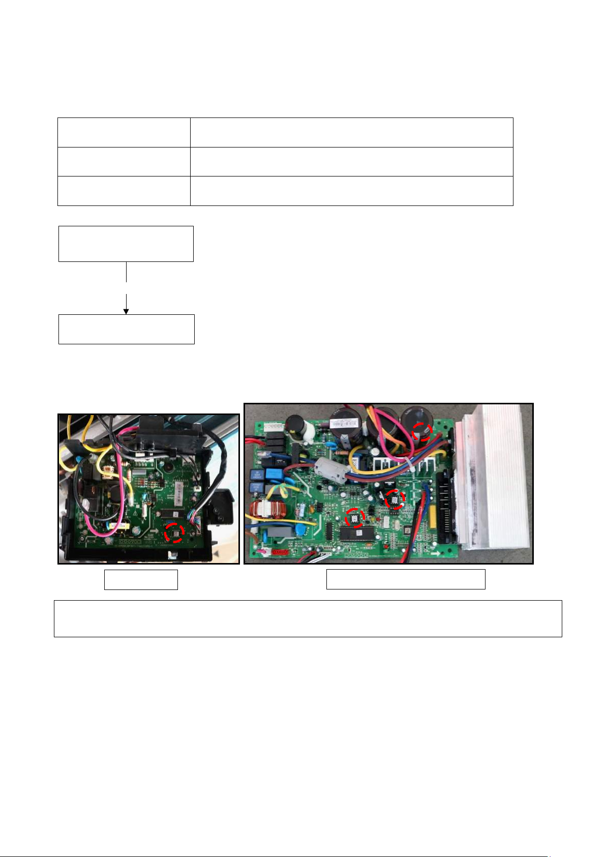
EEPROM: a read-only memory whose contents can be er ased and reprogrammed using a pulsed
voltage. For the location of EEPROM chip, please refer to the below photo s.
Indoor PCB
Note: The two photos above are only for reference, it’s may be not same totally with the one s on
Outdoor PCB
Page 10
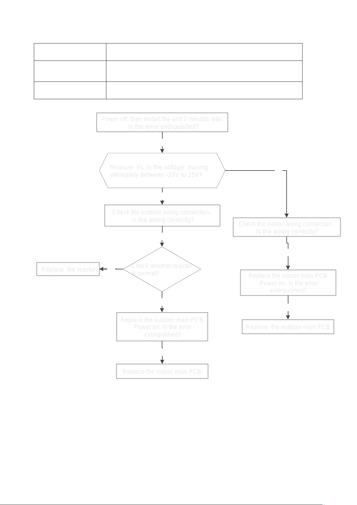
1.3.2 Indoor / outd oor unit’s communi cation diagnosis and s olution(E1)
Error Code
E1
Malfunction decision
Indoor unit does not receive the feedback from outdoor unit
continuously.
Supposed causes
Wiring mistake
Measure Vs
.
Is
the voltage moving
alternately between
-25
V to 25
V
?
Measure Vs
.
Is the voltage moving
alternately between
-25
V to 25
V
?
Yes
Power off,
then restart the unit 2
minutes
later.
Is the error extinguished?
Power off
, then restart the unit
2
minutes
later.
Is the error extinguished?
No
Replace
the outdoor main PCB.
Power on.
Is the error
extinguished?
Replace
the outdoor main PCB.
Power on.
Is the error
extinguished?
Check the outdoor wiring connection
。
Is the wiring
correctly?
Check the outdoor wiring connection。
Is the wiring correctly
?
Replace the indoor main PCB
.
Power on. Is the error
extinguished?
Replace the indoor main PCB
.
Power on
. Is the error
extinguished?
Yes
Replace the outdoor main PCB.
Replace the outdoor main PCB.
No
Replace the indoor main PCB.
Replace the indoor main PCB.
No
Check the indoor wiring connection
。
Is the wiring
correctly?
Check the indoor wiring connection
。
Is the wiring correctly?
Yes
No
Check whether reactor
is normal
?
Check w
hether rea
ctor
is normal?
Yes
Replace
the reactor
Replace
the reactor
No
conditions
Trouble shooting:
during 110 seconds and this condition happens four times
●
● Indoor or outdoor PCB faulty
Page 11
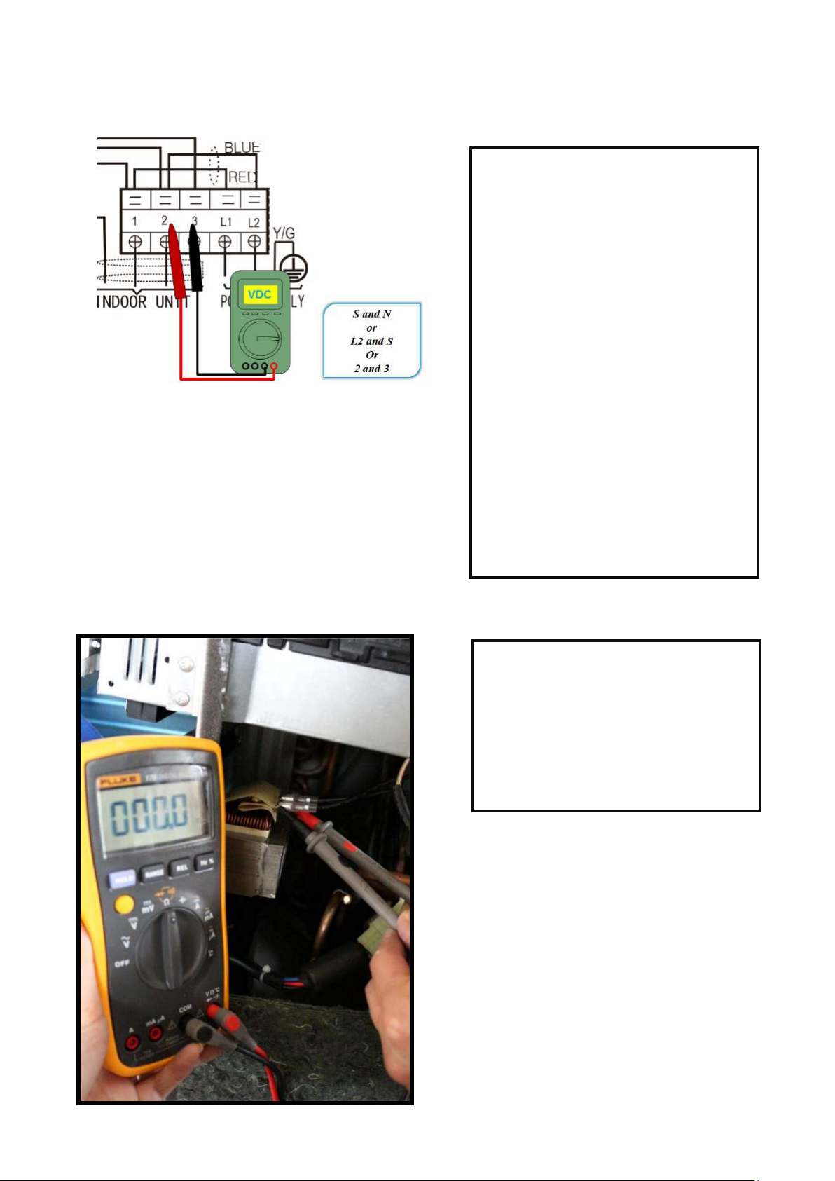
Remark:
Use a multimeter to test t he D C voltage
between 2 port and 3 port of out door
unit. The red pin of mu ltimeter connects
with 2 port while the black pin is for 3
port.
When AC is normal running, the voltage
will move alternately betw een -25V to
25V.
If the outdoor unit has malfunc t io n, the
voltage will move alternately with
positive value.
While if the indoor unit has ma lfunction,
the voltage will be a certain value.
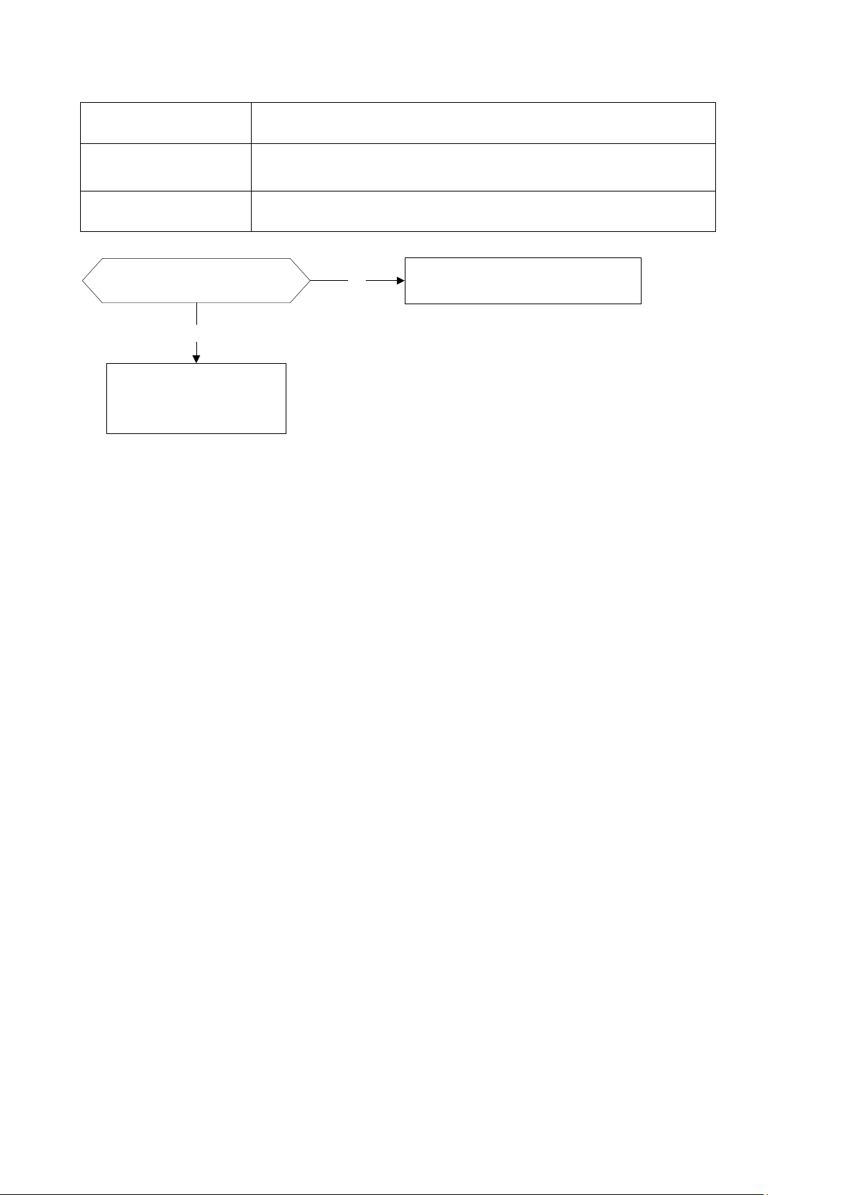
Remark:
Use a multimeter to test the resistance
of the reactor which does not connect
with capacitor.
The normal value should be around
zero ohm. Otherwise, the r eact or m ust
have malfunction.
Page 12
1.3.3 Zero crossi ng detection error diagnos i s and solution (E2)
Error Code
E2
Malfunction decision
When PCB does not receive zero crossing signal feedback for 4
Supposed causes
Connection mistake
Check if the connections and
power supply is normal
?
Correct the connections. Turn on the
unit when the power supply is good.
No
Yes
Indoor main PCB is
defective. Replace indoor
main PCB.
conditions
minutes or the zero crossing signal ti me interval is abnormal.
●
● PCB faulty
Trouble shooting:
Page 13

1.3.4 Fan speed has been out of control diagno sis and solution(E3)
Error Code
E3/F5
Malfunction decision
When indoor fan speed keeps too low (300RPM) for certain time,
Supposed causes
Wiring mistake
PCB faulty
Power off, then restart the
unit 2 minutes later
Shut off the power supply,
Rotate the fan by hand.
The unit operates normally.
Find out the cause and have
it solved
Check the wiring of fan
motor
No
Yes
No
Correct the connections.
No
NoReplace the fan motor
Yes
Yes
Measure the voltage for the
fan motor from the main
PCB refer to the
Appendix 1
Yes
Replace the main PCBNo
conditions
Trouble shooting:
the unit will stop and the LED will display the failure.
●
● Fan ass’y faulty
● Fan motor faulty
●
Page 14

Index 1:
NO.
Color
Signal
Voltage
1
Red
Vs/Vm
280V~380V
2
---
---
---
3
Black
GND
0V
4
White
Vcc
14-17.5V
5
Yellow
Vsp
0~5.6V
6
Blue
FG
14-17.5V
NO.
Color
Signal
Voltage
2
---
---
---
3
Black
GND
0V
4
White
Vcc
14-17.5V
5
Yellow
Vsp
0~5.6V
6
Blue
FG
14-17.5V
1:Indoor or Outdoor DC F an M ot or ( cont r ol chip is in fan motor)
Power on and when the unit is in standby, measure the voltage of pin1-pin3, pin4-pin3 in fan motor
connector. If the value of the voltage is not in the range showing in below table, the PCB must has
problems and need to be replaced.
DC motor voltage input and out put ( voltage: 220-240V~)
DC motor voltage input and out put ( voltage :115V~)
1 Red Vs/Vm 140V~190V
Outdoor DC Fan Motor (control chip is in outdoor PCB)
2.
Power on ,and check if the fan can run normally, if the fan can run normally, the PCB must has
problems and need to be replaced, If the fan can’t run normally, measure the resistanc e of eac h two
pins. If the resistance is not equal to each other, the fan motor must have problems and need to be
replaced, otherwise the PCB must has problems and need to be replaced.
3. Indoor AC Fan Motor
Power on and set the unit running in fan mode at high fan speed. After running for 15 seconds,
measure the voltage of pin1 and pin2. If the value of the voltage is less than 100V(208~240V power
supply)or 50V(115V power supply), t he PC B must has problems and need to be replaced.
Page 15

1.3.5 Open circuit or short circuit of temperature sensor diagnosis a nd solution(E5)
Error Code
E4/E5/F1/F2/F3
Malfunction decision
If the sampling voltage is lower than 0.06V or higher than 4.94V,
Supposed causes
Wiring mistake
PCB faulty
Check the connection
between temperature
sensor and PCB.
Correct the connectionNo
Yes
Replace indoor or outdoor
main PCB
Measure the resistance
value of the sensor
Repalce the sensorNo
Yes
conditions
Trouble shooting:
the LED will display the failure.
●
● Sensor faulty
●
Page 16

1.3.6 Refrigerant Leakag e Detection diagnosis and solution(EC)
Error Code
EC
Malfunction decision
Define the evaporator coil temp.T2 of the com p ressor just starts
<
Supposed causes
T2 sensor faulty
Is there cool air blowing
out from indoor air outlet?
Yes
Yes
Check if T
2 sensor is well
fixed. Correct the installation
or replace T
2 sensor. Does
the problem remain again?
No
Is there any leakage? Especially
the connection parts,
such as the
gas valve and the liquid valve.
No
Shut off the power supply and
turn it on
2 minutes
later.
Is it
still displaying the error code?
Replace indoor PCB.
Yes
Repair the leakage and
recharge the refrigerant.
Yes
Clear the blocking.
Yes
Is there any block ing? (Such as the
capillary or the welded points of the pipes.)
conditions
Trouble shooting:
running as Tcool.
In the beginning 5 minutes after the compressor starts up, if T2
Tcool-2°C(Tcool-35.6°F) does not keep continuous 4
seconds and this situation happens 3 times, the display area
will show “EC” and AC will turn off.
●
● Indoor PCB faulty
● System problems, such as leakage or blocking.
Page 17

1.3.6 Overload current pr ot ec t ion diagnosis and soluti on(F0)
Error Code
F0
Malfunction decision
conditions
An abnormal current rise is detected by checking the specified
current detection circuit.
Supposed causes
Power supply problems.
Compressor malfunction
Check the power supply. Is it
normal?
Check the connections and
wires .Is it well connection?
Stop the unit. Check the power
supply
No
Yes
No
Correct the connections or
replace the wires.
Yes
Replace the outdoor main PCB
Yes
Check the reactor .Is it
normal?
No
Replace the reactor
Is there any blocking?
No
Yes
Clear the blockage
Check the compressor
resistance values refer to the
[
Compressor checking
]. Is it
normal?
Yes
No
Replace the compressor
●
● System blockage
● PCB faulty
● Wiring mistake
●
Trouble shooting:
Page 18

1.3.7 IPM malfunction or IGBT over-strong current protection diagnosis and solution(P0)
Error Code
P0
Malfunction decision
When the voltage signal that IPM send to compressor drive chip
Supposed causes
Wiring mistake
Check if the wiring between main
PCB and compressor . If the wires
and connectors are broken?
Correct the connection or replace
the wires and connectors.
Yes
No
IPM continuity check. Check if the
IPM terminal resistance values are
uniform.
Replace the IPM board or replace the
main PCB if the IPM board and main
PCB are integrated together.
No
Check if the outdoor fan runs
properly or the outdoor unit
ventilation is good.
Yes
No
Please refer to the solution of 【Fan Speed Has Been
Out Of Control】malfunction
Yes
Check if the compressor resistance
values are uniform .
No Replace the compressor.
Yes
Replace the outdoor main PCB if the
main PCB and IPM are separate.
conditions
Trouble shooting:
For 9K~24K:
is abnormal, the display LED will show “P0” and AC will turn off.
●
● IPM malfunction
● Outdoor fan ass’y faulty
● Compressor malfunction
● Outdoor PCB faulty
Page 19

For example:
P-U
P-V
side.
Note: The photos below are only for reference, it’s may be not same totally with the ones on your
Page 20

P-W
N-U
Page 21

N-V
N-W
Page 22

For 30K~36K:
Yes
Check whether the power voltage
is normal
.
Check whether the power voltage
is normal.
Measure whether outdoor terminal
voltage is normal?
Measure whether o
utdoor terminal
voltage is normal?
Restart the unit when the power supply
gets normal
Restart the unit when the power supply
gets normal
No
Yes
No
Reconnect
it
well
Rec
onnect
it
well
Yes
Measure whether
the voltage
between L and N is
normal
?
Measure whether the voltage
between
L
and N
is
normal
?
Yes
Measure whether input voltage of
bridge rectifier
is normal
?
Measure whether input voltage of
bridge rectifier is normal?
No
No
Check the wiring of
power wires well or
correctly
Check the wiring of
power wires well or
correctly
Reconnect it well
Reconnect it well
Check the wiring of L
and N well or correctly
C
heck the wiring of L
and N well or correctly
Rec
onnect
it
well
Reconnect
it
well
Check the wiring of
bridge rectifier well or
correctly
C
heck the wiring of
bridge rectifier well or
correctly
No
Yes
Replace the PFC module(If has)
Replace the PFC module(If has)
No
Measure whether
the voltage
between
P
and N
is
normal
refer to the
Appendix 4?
Measure whether
the voltage
between P and N is normal
refer to the Appendix
4
?
Replace the bridge rectifier
Replace the
bridge rectifier
No
Check whether
bridge
rectifier is normal
Check whether
bridge
rectifier is normal
Check the wiring of reactor
or
inductance
Check the wiring of reactor
or inductance
Reconnect the wiring
Reconnect the wiring No
Check whether reactor or
inductance is normal
Check whether reactor or
inductance is normal
Yes
Replace reactor
or
inductance
Replace reactor or
inductance
No
Check whether the connecting
wire
between main board and the
IPM board is connected tightly
Check whether the connecting
wire
between main board and the
IPM board is connected tightly
Reconnect it well
Reconnect it well
No
Check if the outdoor unit
ventilation is good
Check if the outdoor unit
ventilation is good
Yes
Make the outdoor unit ventilate well
Make the outdoor unit ventilate well
Check whether the refrigerant system is ok
Check whether the refrigerant system is ok
No
Check if the outdoor fan runs
properly
Check if the outdoor fan runs
properly
please refer to the solution of [fan speed
has been out of control malfunction] .
Find out the cause and have it solved.
please refer to the solution of [fan speed
has been out of control malfunction]
.
Find out the cause and have it solved.
No
Yes
No
Yes
Yes
Check the compress is
normal
Check the compress is
normal
Yes
Replace the compressor
Replace the compressor
No
Replace
IPM board
Replace
IPM
board
Replace the outdoor main PCB
Replace the outdoor main PCB
No
Check whether the connecting
wire of the compressor is
connected correctly or tightly
Check whether the connecting
wire
of the compressor is
connected correctly or tightly
Reconnect
it well
Reconnect
it well
No
Yes
Yes
At first test the resis tance bet ween e ver y two por ts of U, V, W of IPM and P, N. If an y result of them is 0 or
close to 0, the IPM is defective. Otherwise, please follow the procedure below:
Page 23

Page 24

1.3.8 Over vol t age or t oo low voltage protection diagnosis and solution(P1 )
Error Code
P1
Malfunction decision
conditions
An abnormal voltage rise or drop is detected by checking the
specified voltage detection circuit.
Supposed causes
Power supply problems.
PCB faulty
Check the power supply
Check the connections and
wires
Stop the unit
No
Yes
No
Correct the connections or
replace the wires.
Yes
Replace the reactor
Yes
No
Replace the IPM board
Check the voltage between P
and N
Check the reactor
Yes
No
Replace outdoor main PCB
P
N
●
● System leakage or block
●
Trouble shooting:
Remark:
Measure the DC voltage
between P and N port . The
normal value should be
around 310V.
Page 25

1.3.9 High temperature protection of IPM module or compressor top diagnosis and
Error Code
P2
Malfunction decision
conditions
If the sampling voltage is not 5V, the LED will display the failure.
Supposed causes
Installation mistake
PCB faulty
Yes
Tighten the screws and apply
silicon grease.
Tighten the screws and apply
silicon grease.
Replace the outdoor control PCB.
Replace the outdoor control PCB.
No
Check if the Fastening screws
on the PCB and IPM radiator
are fixed tightly.
Check if the air flow system
of indoor and outdoor units
are obstructed?
Clear up the air inlet and outlet or the heat
exchanger of indoor and outdoor units.
Yes
No
Yes
Yes
Turn off the power supply and turn
it on 10 minutes later.
Check if the temperature
of compressor Top
Is
more than 90
℃?
No
Check if the refrigerant
system
is normal?
Repair the refrigerant
system .
Replace the outdoor control PCB.
Yes
Check if all the connection, especially
the connection of OLP (Over Load
Protector) sensor is good.
Correct the connection.No
Measure the resistance
between the two ports of
the OLP. Is it zero?
Yes
Replace the OLP.No
Replace the outdoor control PCB.Yes
No
solution(P2)
●
● Power supply problems.
● System leakage or block
●
Trouble shooting:
For 18K,24K,
For other models,
Page 26

1.3.10 Inverter compressor drive error diagnosis and solution(P4)
Error Code
P4
Malfunction decision
An abnormal inverter compressor drive is detected by a special
and so on.
Supposed causes
Wiring mistake
Outdoor PCB faulty
Check if the wiring between main
PCB and compressor connected
well
?
Correct the connection or
replace the wires and
connectors.
No
Check if the IPM installed correctly.
Correct the installation
,
tighten the screws and
apply silicon grease
.
No
IPM continuity check
.
Check if the
IPM terminal resistance values are
uniform.
Yes
Replace the IPM board or replace
the main PCB if the IPM board and
main PCB are integrated together.
No
Check if the outdoor fan runs
properly or the outdoor unit
ventilation is good.
Yes
No
Please refer to the solution of 【
Fan
Speed Has Been Out Of Control
】
malfunction
Yes
Check if the compressor resistance
values are uniform .
No
Replace the compressor
.
Yes
Replace the outdoor main PCB if the
main PCB and IPM are separate
.
Check the reactor or
Inductance
.
Is it normal
?
No
Replace the reactor
or
Inductance
Yes
Yes
conditions
Trouble shooting:
For 9K~24K:
detection circuit, including commun ication signal detection,
voltage detection, compressor rotation speed signal detection
●
● IPM malfunction
● Outdoor fan ass’y faulty
● Compressor malfunction
●
IPM continuity check
Turn off the power, let the large capacity electrolytic capacitors discharge completely, and dismount the IPM. Use a
digital tester to measure the resistance between P and UVWN; UVW and N.
Page 27

Digital tester
Normal resistance value
Digital tester
Normal resistance value
(+)Red
(-)Black
(+)Red
(-)Black
P
N
U
U
V
V
W
W
(+)Red
Yes
Check whether the power voltage
is normal
.
Check whether the power voltage
is normal.
Measure whether outdoor terminal
voltage is normal?
Measure whether outdoor terminal
voltage is normal?
Restart the unit when the power supply
gets normal
Restart the unit when the power supply
gets normal
No
Yes
No
Reconnect it well
Rec
onnect
it
well
Yes
Measure whether
the voltage
between L and N is normal?
Measure whether the voltage
between L and N is
normal
?
Yes
Measure whether input voltage of
bridge rectifier
is normal
?
Measure whether input voltage of
bridge rectifier is normal?
No
No
Check the wiring of
power wires well or
correctly
Check the wiring of
power wires well or
correctly
Reconnect it well
Reconnect it well
Check the wiring of L
and N well or correctly
Check the wiring of L
and N well or correctly
Reconnect it well
Rec
onnect it
well
Check the wiring of
bridge rectifier well or
correctly
Check the wiring of
bridge rectifier well or
correctly
No
Yes
Replace the PFC module
(If has
)
Replace the PFC module(If has
)
No
Measure whether
the voltage
between P and N is normal
refer to the
Appendix 4
?
Measure whether the voltage
between P and N is normal
refer to the Appendix 4
?
Replace the bridge rectifier
Replace the bridge rectifierNo
Check whether bridge
rectifier
is normal
Check whether bridge
rectifier
is normal
Check the wiring of reactor
or inductance
Check the wiring of reactor
or inductance
Reconnect the wiring
Reconnect
the wiring
No
Check whether reactor or
inductance
is normal
Check whether reactor or
inductance is normal
Yes
Replace r
eactor or
inductance
Replace r
eactor or
inductance
No
Check whether the connecting
wire between main board and the
IPM board
is connected tightly
Check whether the connecting
wire between main board and the
IPM board
is connected tightly
Reconnect
it well
Reconnect
it well
No
Check if the outdoor unit
ventilation is good
Check if the outdoor unit
ventilation is good
Yes
Make the outdoor unit ventilate well
M
ake the outdoor unit ventilate well
Check whether the refrigerant system is ok
Check whether the refrigerant system is ok
No
Check if the outdoor fan runs
properly
Check if the outdoor fan runs
properly
please refer to the solution of [fan speed
has been out of control malfunction]
.
Find out the cause and have it solved.
please refer to the solution of [fan speed
has been out of control malfunction] .
Find out the cause and have it solved.
No
Yes
No
Yes
Yes
Check the compress is
normal
Check the compress is
normal
Yes
Replace the compressor
Replace the compressorNo
Replace IPM board
Replace IPM board
Replace the outdoor main PCB
Replace the outdoor main PCB
No
Check whether the connecting
wire of the compressor is
connected correctly or tightly
Check whether the connecting
wire of the compressor is
connected correctly or tightly
Reconnect it well
Reconnect it well
No
Yes
Yes
∞
(Several MΩ)
N
∞
(Several MΩ)
For 30K~36K:
At first test the resistance between every two ports of U, V, W of IPM and P, N. If any result of them is 0 or
close to 0, the IPM is defective. Otherwise, please follow the procedure below:
Page 28

Error Code
P6
Malfunction decision
When the pressure of system reach a certain value, the low
normal ,the protection code will disappear.
Supposed causes
Wiring mistake
System problems.
Whether the wiring
between the low pressure
protector and main control
board is connected well or
correctly
Whether the wiring
between the low pressure
protector and main control
board is connected well or
correctly
Method: Disconnect the
plug. Measure the
resistance of the low
pressure protecto
r. If the
protector is normal the value
is o
Method: Disconnect the
plug. Measure the
resistance of the low
pressure protector. If the
protector is normal the value
is o
Yes
Yes
Connect it well
Connect it well
Replace outdoor main board
Replace outdoor main board
No
Replace low pressure protector
Replace low pressure protector
No
Whether the low
pressure protector
is broken
Whether the low
pressure protector
is broken
Check whether the outdoor
ambient temperature is too
low
Check whether the outdoor
ambient temperature is too
low
No
Stop the unit
Stop the unit
Yes
Open fully valve core of high
pressure valve
Open fully valve core of high
pressure valve
No
Check whether valve core of
high pressure valve is
opened
Check whether valve core of
high pressure valve is
opened
Check if the indoor fan runs
properly in cooling mode
Check if the indoor fan runs
properly in cooling mode
please refer to the solution of [fan
speed has been out of control
malfunction]. Find out the cause and
have it solved
.
please refer to the solution of [fan
speed has been out of control
malfunction]. Find out the cause and
have it solved.
No
Yes
Yes
No
Check whether the
refrigerant system is ok
Check whether the
refrigerant system is ok
Refrigerant is not enough add the
refrigerant
Refrigerant is not enough add the
refrigerant
No
1.3.11 Low pressure protection diagnosi s and solution(P6)
conditions
Trouble shooting:
pressure protector will switch off. After the pressure resume to
●
● Pressure protector faulty
● Fan motor faulty
● PCB faulty
●
Page 29

Main parts check
1. Temper atur e sensor checking
Disconnect the temperature sensor from PCB, measure the resistance value with a tester.
Temperature sensors.
Room temp.(T1) sensor,
Indoor coil temp.(T2) sensor,
Outdoor coil temp.(T3) sensor,
Outdoor ambient temp.(T4) sensor,
Compressor discharge temp.(TP) sensor.
Measure the resistance value of each winding by using the multi-meter.
Page 30

Appendix 1 Temperature Sensor Resistance Value Table for T1,T2,T3,T4 (°C--K)
°C
°F
K Ohm
°C
°F
K Ohm
°C
°F
K Ohm
°C
°F
K Ohm
-20 -4 115.266 20 68 12.6431 60 140 2.35774 100 212 0.62973
-19 -2 108.146 21 70 12.0561 61 142 2.27249 101 214 0.61148
-18 0 101.517 22 72 11.5 62 144 2.19073 102 216 0.59386
-17 1 96.3423 23 73 10.9731 63 145 2.11241 103 217 0.57683
-16 3 89.5865 24 75 10.4736 64 147 2.03732 104 219 0.56038
-15 5 84.219 25 77 10 65 149 1.96532 105 221 0.54448
-14 7 79.311 26 79 9.55074 66 151 1.89627 106 223 0.52912
-13 9 74.536 27 81 9.12445 67 153 1.83003 107 225 0.51426
-12 10 70.1698 28 82 8.71983 68 154 1.76647 108 226 0.49989
-11 12 66.0898 29 84 8.33566 69 156 1.70547 109 228 0.486
-10 14 62.2756 30 86 7.97078 70 158 1.64691 110 230 0.47256
-9 16 58.7079 31 88 7.62411 71 160 1.59068 111 232 0.45957
-8 18 56.3694 32 90 7.29464 72 162 1.53668 112 234 0.44699
-7 19 52.2438 33 91 6.98142 73 163 1.48481 113 235 0.43482
-6 21 49.3161 34 93 6.68355 74 165 1.43498 114 237 0.42304
-5 23 46.5725 35 95 6.40021 75 167 1.38703 115 239 0.41164
-4 25 44 36 97 6.13059 76 169 1.34105 116 241 0.4006
-3 27 41.5878 37 99 5.87359 77 171 1.29078 117 243 0.38991
-2 28 39.8239 38 100 5.62961 78 172 1.25423 118 244 0.37956
-1 30 37.1988 39 102 5.39689 79 174 1.2133 119 246 0.36954
0 32 35.2024 40 104 5.17519 80 176 1.17393 120 248 0.35982
1 34 33.3269 41 106 4.96392 81 178 1.13604 121 250 0.35042
2 36 31.5635 42 108 4.76253 82 180 1.09958 122 252 0.3413
3 37 29.9058 43 109 4.5705 83 181 1.06448 123 253 0.33246
4 39 28.3459 44 111 4.38736 84 183 1.03069 124 255 0.3239
5 41 26.8778 45 113 4.21263 85 185 0.99815 125 257 0.31559
6 43 25.4954 46 115 4.04589 86 187 0.96681 126 259 0.30754
7 45 24.1932 47 117 3.88673 87 189 0.93662 127 261 0.29974
8 46 22.5662 48 118 3.73476 88 190 0.90753 128 262 0.29216
9 48 21.8094 49 120 3.58962 89 192 0.8795 129 264 0.28482
10 50 20.7184 50 122 3.45097 90 194 0.85248 130 266 0.2777
11 52 19.6891 51 124 3.31847 91 196 0.82643 131 268 0.27078
12 54 18.7177 52 126 3.19183 92 198 0.80132 132 270 0.26408
13 55 17.8005 53 127 3.07075 93 199 0.77709 133 271 0.25757
14 57 16.9341 54 129 2.95896 94 201 0.75373 134 273 0.25125
15 59 16.1156 55 131 2.84421 95 203 0.73119 135 275 0.24512
16 61 15.3418 56 133 2.73823 96 205 0.70944 136 277 0.23916
17 63 14.6181 57 135 2.63682 97 207 0.68844 137 279 0.23338
18 64 13.918 58 136 2.53973 98 208 0.66818 138 280 0.22776
19 66 13.2631 59 138 2.44677 99 210 0.64862 139 282 0.22231
Page 31

Appendix 2 Temperature Sensor Resistance Value Table for TP (°C --K)
°C
°F
K Ohm
°C
°F
K Ohm
°C
°F
K Ohm
°C
°F
K Ohm
-20 -4 542.7 20 68 68.66 60 140 13.59 100 212 3.702
-19 -2 511.9 21 70 65.62 61 142 13.11 101 214 3.595
-18 0 483 22 72 62.73 62 144 12.65 102 216 3.492
-17 1 455.9 23 73 59.98 63 145 12.21 103 217 3.392
-16 3 430.5 24 75 57.37 64 147 11.79 104 219 3.296
-15 5 406.7 25 77 54.89 65 149 11.38 105 221 3.203
-14 7 384.3 26 79 52.53 66 151 10.99 106 223 3.113
-13 9 363.3 27 81 50.28 67 153 10.61 107 225 3.025
-12 10 343.6 28 82 48.14 68 154 10.25 108 226 2.941
-11 12 325.1 29 84 46.11 69 156 9.902 109 228 2.86
-10 14 307.7 30 86 44.17 70 158 9.569 110 230 2.781
-9 16 291.3 31 88 42.33 71 160 9.248 111 232 2.704
-8 18 275.9 32 90 40.57 72 162 8.94 112 234 2.63
-7 19 261.4 33 91 38.89 73 163 8.643 113 235 2.559
-6 21 247.8 34 93 37.3 74 165 8.358 114 237 2.489
-5 23 234.9 35 95 35.78 75 167 8.084 115 239 2.422
-4 25 222.8 36 97 34.32 76 169 7.82 116 241 2.357
-3 27 211.4 37 99 32.94 77 171 7.566 117 243 2.294
-2 28 200.7 38 100 31.62 78 172 7.321 118 244 2.233
-1 30 190.5 39 102 30.36 79 174 7.086 119 246 2.174
0 32 180.9 40 104 29.15 80 176 6.859 120 248 2.117
1 34 171.9 41 106 28 81 178 6.641 121 250 2.061
2 36 163.3 42 108 26.9 82 180 6.43 122 252 2.007
3 37 155.2 43 109 25.86 83 181 6.228 123 253 1.955
4 39 147.6 44 111 24.85 84 183 6.033 124 255 1.905
5 41 140.4 45 113 23.89 85 185 5.844 125 257 1.856
6 43 133.5 46 115 22.89 86 187 5.663 126 259 1.808
7 45 127.1 47 117 22.1 87 189 5.488 127 261 1.762
8 46 121 48 118 21.26 88 190 5.32 128 262 1.717
9 48 115.2 49 120 20.46 89 192 5.157 129 264 1.674
10 50 109.8 50 122 19.69 90 194 5 130 266 1.632
11 52 104.6 51 124 18.96 91 196 4.849
12 54 99.69 52 126 18.26 92 198 4.703
13 55 95.05 53 127 17.58 93 199 4.562
14 57 90.66 54 129 16.94 94 201 4.426
15 59 86.49 55 131 16.32 95 203 4.294
16 61 82.54 56 133 15.73 96 205 4.167
17 63 78.79 57 135 15.16 97 207 4.045
18 64 75.24 58 136 14.62 98 208 3.927
19 66 71.86 59 138 14.09 99 210 3.812
Page 32

Appendix 3:
-5
23
21
69.8
51
123.8
82
179.6
113
235.4
-4
24.8
22
71.6
52
125.6
83
181.4
114
237.2
-3
26.6
23
73.4
53
127.4
84
183.2
115
239
-2
28.4
24
75.2
54
129.2
85
185
116
240.8
-1
30.2
25
77
55
131
86
186.8
117
242.6
0
32
25.5
77.9
56
132.8
87
188.6
118
244.4
0.5
32.9
26
78.8
57
134.6
88
190.4
119
246.2 1 33.8
27
80.6
58
136.4
89
192.2
120
248
1.5
34.7
28
82.4
59
138.2
90
194
121
249.8
2
35.6
29
84.2
60
140
91
195.8
122
251.6
2.5
36.5
30
86
61
141.8
92
197.6
123
253.4
3
37.4
31
87.8
62
143.6
93
199.4
124
255.2
3.5
38.3
32
89.6
63
145.4
94
201.2
125
257 4 39.2
33
91.4
64
147.2
95
203
126
258.8
4.5
40.1
34
93.2
65
149
96
204.8
127
260.6
5
41
35
95
66
150.8
97
206.6
128
262.4 6 42.8
36
96.8
67
152.6
98
208.4
129
264.2
7
44.6
37
98.6
68
154.4
99
210.2
130
266
8
46.4
38
100.4
69
156.2
100
212
131
267.8 9 48.2
39
102.2
70
158
101
213.8
132
269.6
10
50
40
104
71
159.8
102
215.6
133
271.4
11
51.8
41
105.8
72
161.6
103
217.4
134
273.2
12
53.6
42
107.6
73
163.4
104
219.2
135
275
13
55.4
43
109.4
74
165.2
105
221
136
276.8
14
57.2
44
111.2
75
167
106
222.8
137
278.6
15
59
45
113
76
168.8
107
224.6
138
280.4
16
60.8
46
114.8
77
170.6
108
226.4
139
282.2
17
62.6
47
116.6
78
172.4
109
228.2
140
284
18
64.4
48
118.4
79
174.2
110
230
141
285.8
19
66.2
49
120.2
80
176
111
231.8
142
287.6
20
68
50
122
81
177.8
112
233.6
143
289.4
9ΔT(℃)
ΔT(℉) =
5
°C °F °C °F °C °F °C °F °C °F
Page 33

Normal voltage of P and N
208-240V(1-phase,3-phase)
380-420V(3-phase)
In standby
around 310VDC
around 530VDC
In operation
With partial
module
>200VDC
>310VDC
>370VDC
>450VDC
Appendix 4
1.
With passive
PFC module
active PFC
With fully active
PFC module
/
Page 34

2. Compressor checking
Position
Resistance Value
ASN98D22UFZ
ASM135D23UFZ
ATF235D22UMT
ATF250D22UMT
Blue - Red
Blue - Black
Red - Blue
Measure the resistance value of each winding by using the tester.
1.57Ω
1.75 Ω
0.75 Ω
0.75 Ω
Page 35

3. Fan Motor
Model
YKT-32-6-
202L
YKT-32-6-
3L
YKT-48-6-
206
YKT-63-6-
200L
Brand
Tongde
Welling
Welling
Welling
Black –
Main
Ω
86
213
152
88.5
Blue –
AUX
Ω
64
156
142
138
Measure the resistance value of each winding by using the tester.
Red
Black
Page 36

4. Pressure On Service Port
ODT
IDT
75
(23.89)
85
(29.44)
95
(35)
105
(40.56)
115
(46.11)
BAR
70/59
8.2
7.8
8.1
8.6
10.1
BAR
75/63
8.6
8.3
8.7
9.1
10.7
BAR
80/67
9.3
8.9
9.1
9.6
11.2
ODT
IDT
75
(23.89)
85
(29.44)
95
(35)
105
(40.56)
115
(46.11)
PSI
70/59
119
113
117
125
147
PSI
75/63
124
120
126
132
155
PSI
80/67
135
129
132
140
162
ODT
IDT
75
(23.89)
85
(29.44)
95
(35)
105
(40.56)
115
(46.11)
MPA
70/59
0.82
0.78
0.81
0.86
1.01
MPA
75/63
0.86
0.83
0.87
0.91
1.07
MPA
80/67
0.93
0.89
0.91
0.96
1.12
75 (23.89
85 (29.44
95 (35
105 (40.56
115 (46.11
70/59
75/63
80/67
Cooling chart:
°F(°C)
°F(°C)
°F(°C)
12,0
10,0
8,0
6,0
4,0
2,0
0,0
)
)
)
)
)
Page 37

Heating Chart:
(°C)
ODT
IDT
(13.89/11.67)
(8.33/6.11)
(2.78/0.56)
(-2.78/-5)
(-8.33/-10.56)
BAR
55
30.3
28.5
25.3
22.8
20.8
BAR
65
32.5
30.0
26.6
25.4
23.3
BAR
75
33.8
31.5
27.8
26.3
24.9
(°C)
ODT
IDT
(13.89/11.67)
(8.33/6.11)
(2.78/0.56)
2.78/-5)
(-8.33/-10.56)
PSI
55
439
413
367
330
302
PSI
65
471
435
386
368
339
PSI
75
489
457
403
381
362
ODT
IDT
(13.89/11.67)
(8.33/6.11)
(2.78/0.56)
2.78/-5)
(-8.33/-10.56)
MPA
55
3.03
2.85
2.53
2.28
2.08
MPA
65
3.25
3.00
2.66
2.54
2.33
MPA
75
3.38
3.15
2.78
2.63
2.49
No.
Parts name
Procedures
Remarks
57/53
47/43
37/33
27/23
17/13
55
65
75
°F
°F
°F
(°C)
40,0
35,0
30,0
57/53
57/53
57/53
47/43
47/43
47/43
37/33
37/33
37/33
27/23
27/23 (-
27/23 (-
17/13
17/13
17/13
25,0
20,0
15,0
10,0
5,0
0,0
(13.89/11.67)
(8.33/6.11)
(2.78/0.56)
(-2.78/-5)
(-8.33/-10.56)
2. Disassembly Instructions
Note: This part is for reference, the photos may have sli ght di f f er ence with your machine.
2.1 Indoor unit
Page 38

1
Front panel
How to remove the front pane l.
1) Pull the below side of
①1 screw
②
⑤
the panel toward you and
remove screw of the cover.
2) Release the connector of
the display ass’y.
3) Release the two clips and
then remove the panel.
4) Remove the fi lter and the
horizontal louver.
5) Remove the three screws
and then remove the panel
ass’y.
Page 39

2
Electrical
parts
How to remove the electric al
②
③
④
⑤
parts.
1) Remove the front
panel from procedure 1.
2) Pull out the room temp.
sensor (T1). Remove the two
screws for the ground
connection.
3) Remove the fixing screw.
4) Pull out the coil temp.
sensor.
5) From the side direction,
open the electronic control box
cover fixing by clips. Pull out
the fan motor connector and
swing motor connector. Then
remove the electronic con trol
box.
 Loading...