

Page 1

User Manual
SMP Gateway
Page 2

Copyright Cooper Power Systems © 2008, hardware, software and manual
The in formati on in th is documen t is subject to change w ithout notice .
Cooper Power Systems
Energy Automation Solutions
730 Commerciale St.
Suite 200
Saint-Jean-Chrysostome (Quebec)
Canada
G6Z 2C5
Phone: +1.418.834.0009
Fax: +1.514.227.5256
Email: [email protected]
Web Site: http://www.cybectec.com
GUI-00316-00001 T, version 18
Page 3

Contents
1 Welcome 1
1.1 SMP Gateway Models ........................................................................................... 1
1.2 Related Documentation ......................................................................................... 2
1.3 Getting Assistance with Cybectec Products .......................................................... 3
1.4 Getting Started ....................................................................................................... 3
1.5 Document Overview .............................................................................................. 4
2 Principles of Operation 7
2.1 Logical Architecture .............................................................................................. 7
2.1.1 Masters and Slaves .................................................................................. 7
2.1.2 Introducing the SMP Gateway in the Automation System ...................... 8
2.1.3 SMP Gateway Internals ........................................................................... 9
2.1.4 Communications Components ................................................................ 9
2.2 Configuring the SMP Gateway ............................................................................ 10
2.2.1 The Transparent SMP Gateway ............................................................ 11
2.2.2 Using the SMP Gateway as a Protocol Translator ................................ 13
2.2.3 Using the SMP Gateway as a Data Concentrator or Device
Multiplexer ............................................................................................ 14
2.2.4 Using the SMP Gateway as a Communications Processor .................... 15
2.2.5 Putting it all Together ............................................................................ 16
2.2.6 Securing the Substation ......................................................................... 17
3 SMP Tools Overview 19
4 SMP Manager 21
4.1 Starting SMP Manager and Logging On ............................................................. 21
4.2 Main Window ...................................................................................................... 22
4.3 Adding an SMP Gateway .................................................................................... 22
4.4 Information Provided by the SMP Gateway Icon ................................................ 23
4.5 Customizing the Display ..................................................................................... 24
4.5.1 Adding or Removing a Column ............................................................ 25
SMP Gateway User Manual • i
Page 4

4.5.2 Changing the Position of a Column ...................................................... 25
5 Configuring the SMP Gateway 27
5.1 Creating Master Protocol Instances ..................................................................... 28
5.1.1 Creating a Master Protocol Instance from a Template .......................... 29
5.1.2 Creating a Master Protocol Instance Manually ..................................... 30
5.1.3 Configuring the Master Protocol General Settings................................ 30
5.2 Configuring the Data Points ................................................................................ 31
5.2.1 Adding Data Points from a Protocol Template ..................................... 33
5.3 Creating a Template from a Master Protocol Instance ........................................ 33
5.4 Duplicating a Master Protocol Instance ............................................................... 34
5.5 Configuring the Communications Links ............................................................. 34
5.5.1 Configuring the Serial Port Interfaces ................................................... 34
5.5.2 Configuring the Operation of the Serial Ports ....................................... 36
5.5.3 Configuring TCP/IP Master Connections ............................................. 37
5.6 Associating a Master Protocol Instance with a Communications Link ............... 37
5.7 Testing the Configuration .................................................................................... 38
5.7.1 Validating and Saving the Configuration .............................................. 38
5.7.2 Sending the Configuration to the SMP Gateway .................................. 39
5.7.3 Retrieving an SMP Gateway Configuration File ................................... 40
5.8 Working with SMP Config .................................................................................. 40
5.8.1 Selecting Cells and Lines ...................................................................... 40
5.8.2 Duplicating a Line ................................................................................. 41
5.8.3 Copying a Value to a Group of Cells .................................................... 41
5.8.4 Resequencing a Group of Lines ............................................................ 42
5.8.5 Deleting an Item .................................................................................... 43
5.8.6 Using Tooltips ....................................................................................... 44
5.8.7 Searching and Replacing Points in a Configuration .............................. 44
6 Viewing the SMP Log Files 47
6.1 Information Provided by SMP Log ..................................................................... 47
6.2 SMP Log Features ............................................................................................... 48
6.2.1 Searching in SMP Log .......................................................................... 48
6.2.2 Printing a Log ........................................................................................ 48
6.2.3 Saving a Log File .................................................................................. 48
6.2.4 Viewing Multiple Log Folders at Once ................................................. 49
6.2.5 Changing How Time Information is Displayed .................................... 49
ii • SMP Gateway User Manual
Page 5

7 Viewing Protocol Exchanges in Real Time 51
7.1 Information Provided by SMP Trace ................................................................... 51
7.2 SMP Trace Features ............................................................................................ 52
7.2.1 Searching in SMP Trace ........................................................................ 52
7.2.2 Printing Traces ...................................................................................... 53
7.2.3 Recording Live Traces .......................................................................... 53
7.2.4 Saving all the Scrolled Information ....................................................... 54
7.2.5 Changing How Time Information is Displayed .................................... 54
8 Viewing Communications Statistics in Real Time 55
8.1 Information Provided by SMP Stats .................................................................... 56
8.2 SMP Stats Features .............................................................................................. 56
8.2.1 Resetting Statistics ................................................................................ 56
8.2.2 Printing Statistics .................................................................................. 57
8.2.3 Changing How Time Information is Displayed .................................... 57
9 Using a Web Browser to View Data in Real Time 59
9.1 Connecting to the SMP Gateway’s Website ........................................................ 59
9.2 Navigating Through the SMP Gateway’s Website .............................................. 59
9.3 Applying a Filter to a Data Point Display ........................................................... 60
9.4 Acknowledging Data Point Value Changes ........................................................ 61
10 Connecting the SMP Gateway to a Control Center 63
10.1 Creating Slave Protocol Instances ....................................................................... 63
10.2 Configuring Slave Protocol Instances ................................................................. 63
10.3 Subscribing to the Master Data Points ................................................................. 64
10.4 Configuring the Data Points ................................................................................ 66
10.5 Configuring the Communications Links ............................................................. 66
10.5.1 Setting up a TCP/IP Slave Connection .................................................. 66
10.6 Associating a Slave Protocol Instance with a Communications Link ................. 66
10.7 Validating and Activating the Configuration ...................................................... 67
10.8 Testing the Configuration .................................................................................... 67
11 Using the Web Server’s Commissioning Tool 69
11.1 Configuring an SMP Gateway for Commissioning ............................................. 69
11.2 Activating the Commissioning Feature ............................................................... 70
11.3 Opening a Commissioning Session ..................................................................... 71
SMP Gateway User Manual • iii
Page 6

11.3.1 The Commissioning Tab ....................................................................... 72
11.3.2 Forcing an Input Point ........................................................................... 73
11.3.3 Un-Forcing an Input Point ..................................................................... 73
11.3.4 Performing a Control Operation ............................................................ 74
11.3.5 Closing the Commissioning Session ..................................................... 75
11.4 Deactivating the Commissioning Feature ............................................................ 75
12 Interconnecting SMP Gateways 77
12.1 Configuring the Slave SMP Gateway .................................................................. 78
12.2 Configuring the Master SMP Gateway ................................................................ 81
12.2.1 Updating the Interconnections Master’s Data Point List ....................... 83
12.3 Verifying the Interconnection Between the SMP Gateways ............................... 84
13 Security 85
13.1 Meeting NERC CIP Requirements ...................................................................... 85
13.2 Substation Network Security Considerations ...................................................... 86
13.2.1 Setting Up a Secure Substation LAN .................................................... 86
13.2.2 Using SMP Tools through a Substation LAN Firewall ......................... 87
13.3 Extending the SMP Gateway Security Model ..................................................... 89
13.4 Managing the Security Database of One or More SMP Gateways ...................... 89
13.4.1 Getting Started ...................................................................................... 89
13.4.2 Accessing the Login Information Dialog Box ....................................... 90
13.4.3 Displaying an Appropriate Use Banner at Login .................................. 90
13.4.4 Defining your Authentication Policy .................................................... 91
13.4.5 Groups and Privileges ........................................................................... 94
13.4.6 Editing User Groups and Privileges ...................................................... 94
13.4.7 Managing User Groups and Privileges .................................................. 96
13.4.8 Validating and Saving the Security Database ....................................... 97
13.4.9 Sending the Security Database to One or More SMP Gateways ........... 98
13.4.10 Retrieving the Security Database of an SMP Gateway ......................... 99
13.4.11 Removing the Security Database from One or More
SMP Gateways .................................................................................... 100
13.4.12 Unlocking a User Account .................................................................. 100
13.4.13 Viewing the Security Log ................................................................... 101
13.5 File certification and integrity checking ............................................................ 102
13.5.1 Detecting an integrity check failure .................................................... 102
13.5.2 Recovering from an integrity failure ................................................... 102
13.6 Using VPN Connections .................................................................................... 102
iv • SMP Gateway User Manual
Page 7

13.6.1 Manually Setting Up a VPN Connection ............................................ 103
13.7 Configuring the Firewall ................................................................................... 104
13.7.1 Creating the Firewall in SMP Config .................................................. 104
13.7.2 Setting General Parameters ................................................................. 105
13.7.3 Setting Firewall Rules ......................................................................... 105
13.8 Locking Incoming RAS and Passthrough Connections ..................................... 106
13.8.1 Locking or Unlocking All Incoming RAS Dialup Connections .......... 107
13.8.2 Locking or Unlocking a Passthrough Connection ............................... 108
14 Using Passthrough Connections 109
14.1 Principles of Operation ...................................................................................... 109
14.2 Setting up Passthrough Connections ................................................................. 111
14.2.1 Defining SMP Gateway Passthrough Settings .................................... 111
14.2.2 Installing a Loopback Cable, if Necessary .......................................... 112
14.2.3 Setting Up a List of Applications and Loopback Connections ............ 113
14.3 Connecting to the Device .................................................................................. 116
14.4 Testing the Passthrough Connection ................................................................. 116
14.5 Deactivating the Passthrough Connection ......................................................... 116
14.6 Using the Trace of Passthrough Connection Events .......................................... 117
14.7 Changing How Time Information is Displayed in SMP Connect ..................... 118
15 Retrieving Event Files From Devices 119
15.1 Defining System Folders ................................................................................... 119
15.2 Configuring Master Protocols for Event File Retrieval ..................................... 121
15.3 Retrieving files from another SMP Gateway ..................................................... 122
16 Using the Annunciator Interface 125
16.1 Activating the Annunciator Option ................................................................... 127
16.2 Setting Up the Annunciator ............................................................................... 128
16.2.1 Configuring Alarm Inputs ................................................................... 129
16.2.2 Setting Up the Alarms Page ................................................................ 131
16.2.3 Setting Up the Blocked Page ............................................................... 134
16.2.4 Setting Up the History Page ................................................................ 135
16.2.5 Setting Up the System State Page ....................................................... 137
16.2.6 Creating a User-Defined Readings Page ............................................. 140
16.2.7 Selecting the Pages to Display ............................................................ 147
16.2.8 Selecting the Page Displayed at Startup .............................................. 148
SMP Gateway User Manual • v
Page 8

16.2.9 Changing How Time Information is Displayed .................................. 148
16.2.10 Setting Up an Alarm Buzzer ............................................................... 149
16.2.11 Temporarily Deactivating the Annunciator ......................................... 149
16.3 Setting Up the Touch Screen ............................................................................. 149
16.3.1 Connecting the Touch Screen to the SMP Gateway............................ 149
16.3.2 Setting Up a Screen Saver using SMP Config .................................... 150
16.4 Uploading the Configuration to the SMP Gateway ........................................... 150
16.5 Calibrating the Touch Screen ............................................................................ 151
16.6 Using the SMP Gateway’s Annunciator ............................................................ 151
16.6.1 Navigating Through the Different Pages ............................................. 151
16.6.2 Managing Alarms ................................................................................ 152
16.6.3 Blocking Alarm Inputs ........................................................................ 154
16.6.4 Using the Single Alarm Display .......................................................... 155
16.6.5 Using the History Log ......................................................................... 155
16.6.6 Monitoring System Status ................................................................... 157
16.6.7 Performing Control Operations From a Readings Page ...................... 159
16.6.8 Using the Screen Saver ....................................................................... 160
17 The SMP Gateway’s Automation Functions 163
17.1 The SMP Gateway Automation Functions Module ........................................... 163
17.1.1 Adding an Automation Functions Instance ......................................... 164
17.1.2 Defining an Automation Function ....................................................... 165
17.1.3 Understanding Automation Functions Settings ................................... 168
17.1.4 Using the Logic Processor................................................................... 168
17.2 The Soft PLC ..................................................................................................... 176
17.2.1 The CoDeSys Development Environment .......................................... 176
17.2.2 Using CoDeSys to Create SMP Gateway Automation Scripts ............ 177
18 Using Syslog with an SMP Gateway 178
18.1 Setting Up Syslog .............................................................................................. 178
19 Redundancy 181
19.1 Redundant Group Operation .............................................................................. 181
19.1.1 Redundant IEDs .................................................................................. 182
19.1.2 Giving Priority to an SMP Gateway of the Group .............................. 182
19.2 Grouping 2 SMP Gateways for Redundancy ..................................................... 183
19.2.1 Setting Up a Redundancy Group Using SMP Manager ...................... 183
vi • SMP Gateway User Manual
Page 9

19.2.2 SMP Manager’s Redundancy Column ................................................ 187
19.3 Managing Redundancy ...................................................................................... 188
19.3.1 Forcing an Active SMP Gateway to Fall On Standby ......................... 188
19.3.2 Additional Failover Conditions ........................................................... 189
19.3.3 Modifying the Redundancy Settings of an Existing Group ................. 189
19.3.4 Ungrouping SMP Gateways ................................................................ 189
19.3.5 Testing and Validating the Configuration ........................................... 189
19.3.6 Monitoring Redundancy Status ........................................................... 190
19.3.7 Testing a Redundant Network ............................................................. 190
19.4 Hot Standby ....................................................................................................... 191
19.5 Teaming NICs for Network Fault Tolerance (SMP 16 Only) ........................... 192
20 Setting Up the SNMP Server 193
20.1 SNMP Traps ...................................................................................................... 193
20.2 Configuring the SNMP Server .......................................................................... 193
21 Time Adjustment 195
21.1 Monitoring Time Information ........................................................................... 195
21.2 Setting SMP Gateway’s Internal Clock ............................................................. 195
21.3 Automatic Clock Adjustment ............................................................................ 196
21.3.1 About GPS, IRIG-B and SNTP ........................................................... 197
21.3.2 Configuring the SMP 16 GPS Clock Option ....................................... 198
21.3.3 Using IRIG-B for Internal Clock’s Adjustment .................................. 198
21.3.4 Setting Up the SMP Gateway as an SNTP Client ............................... 199
21.3.5 Using a SCADA Protocol’s Time Adjustment Feature ....................... 200
21.4 Using the SMP Gateway as a Time Source ....................................................... 200
21.4.1 Configuring IRIG-B Time Distribution .............................................. 201
21.4.2 Setting Up the SMP Gateway to Act as an SNTP Server .................... 201
21.4.3 Adjusting Devices Clocks Using Master Protocols ............................. 202
22 SMP Tools Remote Access to the SMP Gateway 203
22.1 Windows XP Setup Procedures ......................................................................... 203
22.1.1 Setting Up a Dial-Up (Modem) Connection ....................................... 203
22.1.2 Setting Up a Direct Serial Connection ................................................ 206
22.2 Windows 2000 Setup Procedures ...................................................................... 208
22.2.1 Setting Up a Dial-Up (Modem) Connection ....................................... 209
22.2.2 Setting Up a Direct Serial Connection ................................................ 211
SMP Gateway User Manual • vii
Page 10

23 Using a Dial-Up Connection for DNP3 or IEC 60870-5-101 215
23.1 Specifying which serial ports have modems ..................................................... 216
23.2 Creating a modem pool ..................................................................................... 216
23.3 Adding a modem to a modem pool ................................................................... 217
23.4 Adding a modem pool master connection ......................................................... 219
23.5 Adding a modem pool slave connection ............................................................ 219
24 Updating SMP Gateway’s Software and Tools 221
24.1 Software Architecture of the SMP Gateway ..................................................... 221
24.2 Updating the SMP Tools on the PC ................................................................... 222
24.3 Updating the SMP Gateway Software ............................................................... 222
24.3.1 Updating the SMP Gateway Firmware ............................................... 222
24.3.2 Updating the SMP Gateway Application ............................................ 224
24.3.3 Updating the Configuration File ......................................................... 225
25 Activating a New License 226
25.1 Updating your License Information .................................................................. 226
26 Miscellaneous SMP Tool Features 229
26.1 SMP Manager Features ..................................................................................... 229
26.1.1 Modifying SMP Manager’s Settings ................................................... 229
26.2 SMP Config Features ........................................................................................ 230
26.3 System Data Points ............................................................................................ 231
26.4 SMP Loader ....................................................................................................... 234
26.4.1 Setting Up SMP Loader ...................................................................... 235
26.4.2 Main Window ..................................................................................... 236
26.4.3 Transferring Files to the SMP Gateway .............................................. 237
26.4.4 Log File 239
26.4.5 Updating Bootstraps Under Unusual Circumstances .......................... 239
27 Telnet-Based Functions 241
27.1 Starting a Telnet Session ................................................................................... 241
27.2 Firewall Manager .............................................................................................. 241
27.2.1 R Command ........................................................................................ 242
27.2.2 S Command ......................................................................................... 242
27.2.3 H Command ........................................................................................ 242
27.2.4 Q Command ........................................................................................ 243
viii • SMP Gateway User Manual
Page 11

27.3 Time and Date ................................................................................................... 243
27.4 Clock Manager .................................................................................................. 243
27.4.1 D Command ........................................................................................ 244
27.4.2 H Command ........................................................................................ 244
27.4.3 Q Command ........................................................................................ 244
27.5 Elo Touchscreen Driver Manager ...................................................................... 244
28 Troubleshooting 247
28.1.1 Getting Additional Help ...................................................................... 247
28.1.2 Creating an SMP Gateway Report File ............................................... 248
28.1.3 Viewing an SMP Gateway Report File ............................................... 249
28.2 Startup Problems ............................................................................................... 249
28.2.1 No Configuration File ......................................................................... 249
28.2.2 Protocols Failed ................................................................................... 250
28.2.3 Critical Components Missing .............................................................. 251
28.3 Communications Problems ................................................................................ 251
28.3.1 Physical Layer ..................................................................................... 252
28.3.2 Link Layer ........................................................................................... 252
28.3.3 Protocol Layer ..................................................................................... 252
28.4 Problems with Data Validity ............................................................................. 253
28.5 Problems Executing a Control Operation .......................................................... 253
28.6 Firewall-Related Problems ................................................................................ 254
SMP Gateway User Manual • ix
Page 12

Page 13

Figures
Figure 1 Master and slave systems ............................................................................................. 8
Figure 2 The SMP Gateway as a Master-and-slave system ........................................................ 8
Figure 3 The SMP Gateway real-time data exchange ................................................................. 9
Figure 4 SMP Gateway communications components .............................................................. 10
Figure 5 The transparent SMP Gateway ................................................................................... 12
Figure 6 Additional SMP Gateway functions ........................................................................... 13
Figure 7 The SMP Gateway protocol translator ........................................................................ 14
Figure 8 The SMP Gateway data concentrator ......................................................................... 15
Figure 9 The SMP Gateway as a communications processor ................................................... 16
Figure 10 The substation SMP Gateway ..................................................................................... 17
Figure 11 The SMP Gateway with a firewall .............................................................................. 18
Figure 12 Using a passthrough connection ............................................................................... 110
SMP Gateway User Manual • xi
Page 14

Page 15

1 Welcome
Congratulations on acquiring your new SMP Gateway! You now have unlimited co nnectivity for
all the equipment in your substation.
In this manual, we will show you how to use the SMP Gateway to integrate existing and new
RTUs, IEDs, PLCs and control centers into a single modern, homogeneous substation automation
system.
You will learn how to set up your SMP Gateway as a:
Protocol Translator – The SMP Gateway translates standard or proprietary device protocols
to control center protocols such as DNP3, TEJAS, IEC-60870-5-101/103/104 or IEC-61850
(UCA 2.0).
Data Concentrator – The SMP Gateway collects the data from all connected devices,
regardless of protocol, and makes it available to control centers using LAN, WAN, modem or
serial connections.
Terminal Server – The SMP Gateway supports centralized maintenance, monitoring and
control of all devices by using the passthrough communications mode.
Substation Communications Gateway – The advanced capabilities of the SMP Gateway
make it the ideal choice for any substation automation project.
1.1 SMP Gateway Models
There are currently 3 SMP Gateway models:
The SMP 4 has 4 ports. It comes in a compact and economical format that allows it to be
installed directly within relay protection enclosures. There is also an optional internal modem
available, which allows the SMP 4 to communicate with a SCADA or device via a dialup
connection.
The SMP 16, which can be mounted in a 19-inch rack, comes in two vers i ons , both of which
have the same basic characteristics:
The SMP 16/CP is a gateway that offers 16 RS-232/422/485 universal serial ports,
2 Ethernet ports and an integrated modem.
SMP Gateway User Manual • 1
Page 16

The SMP 16/SG has, in addition, expansion slots where accessories and options can be
added to make it an ideal communications gateway for all your automation projects.
Both versions can also be equipped with the PM option, a new 1.1 GHz Pe nt i um-M
processor that improves the gateway's speed tenfold. This is ideal for high-capacity
application or complex automation schemes.
The manual applies to all models, and differences are indicated where applicable. Refer to your
SMP Gateway installation guide for a detailed description of your particular SMP Gateway model.
1.2 Related Documentation
This manual provides you with the basic information you need to get started with your
SMP Gateway. To reduce paper use, we have included the following related documentation on the
CD-ROM you received with the product. Should you want printed documents, you can order them
from Cooper Power Systems using reference number P-DPRN-0102.
Your Documentation folder contains the following related documents:
SMP 4-20 SMP 8-40 Installation Guide, GUI-00316-00027 T.
This document gives you detailed instructions on installing and setting up the SMP 4-20 or
SMP 8-40.
SMP 4 Installation Guide, GUI-00316-00026 T.
This document gives you detailed instructions on installing and setting up the SMP 4.
SMP 16 Installation Guide, GUI-00316-00032 T.
This document gives you detailed instructions on installing and setting up the SMP 16/CP or
the SMP 16/SG.
SIOM Adding Serial Ports to Your SMP, AUT-00123-00432 T.
This document describes how to add serial ports to an SMP 4-20 or SMP 8-40.
SMP 16 GPS Clock Option Installation Guide AUT-00316-0047-T.
This document describes how to install the wiring and setup the software if you have the GPS
clock option for the SMP 16.
Master Protocol Common Concepts.
This document describes the concepts and settings common to the protocols used by most
substation devices. Separate documents describe the protocol-specific settings.
SMP 4 Diagnostics Reference Guide, GUI-00316-00040 T.
This document takes you through the steps required to run diagnostic tests on the SMP 4.
SMP 16 Diagnostics Reference Guide, GUI-00316-00036 T.
This document takes you through the steps required to run diagnostic tests on the SMP 16.
SMP 4-20 SMP 8-40 Diagnostics Referenc e Guide, GUI-00316-00024 T.
This document takes you through the steps required to run diagnostic tests on the SMP 4-20
or SMP 8-40.
2 • SMP Gateway User Manual
Page 17

1.3 Getting Assistance with Cybectec Products
If you have any questions regarding the performance, application, testing or repair of this or any
other component of the Cybectec product line, do not hesitate to contact us. Our staff will be
happy to assist you.
Cybectec Techni cal Support
Cooper Po wer Sy s tems
Energy Au toma tion Solutions
730 Commerciale Street, Suite 200
Saint- Jean- Chrysostome, Quebec
Canada G6Z 2C5
Email: [email protected]
Phone: +1.418.834.0009
Fax: +1.514.227.5256
You can reach us between 8 a.m. and 5 p.m. EST. For emergency service on weekends and
holidays, simply leave your name and phone number on our pager at +1.418.260.6000. We will
get back to you as soon as possible.
1.4 Getting Started
When you receive your SMP Gateway, you have to go through several steps before you can
perform the tasks described in this document. Namely, you have to do the following:
Unpack the SMP Gateway.
Install the SMP Gateway.
Set-up the SMP Gateway.
Install the PC software.
Make the SMP Tools aware of your new SMP Gateway.
Load the SMP Gateway firmware.
All of these steps are explained in detail in the following documents:
SMP 4-20 SMP 8-40 Installation Guide, GUI-00316-0002 7 T
SMP 4 Installation Guide, GUI-00316-00026 T.
SMP 16 Installation Guide, GUI-00316-00032 T.
Make sure you have performed all the steps described in those documents before proceeding
with the material explained in the present document.
SMP Gateway User Manual • 3
Page 18

1.5 Document Overview
Once you have performed all the steps explained in your SMP Gateway installation guide, you are
ready to perform the following tasks, as described in this user manual:
Configure your SMP Gateway so that it can communicate with your devices:
Define the hardware.
Configure the master protocol instances that will communicate with your substation
devices.
Configure the data points.
Set-up the communications links between the SMP Gateway and the substation devices.
Associate master protocol instances with communications links.
Validate, activate and test your configuration.
View the following information in real time:
The SMP Gateway log files.
Protocol exchanges.
Communications statistics.
Data points, using a Web browser.
Configure your SMP Gateway so that it can communicate with one or more control centers:
Configure a slave protocol instance for each control center.
Have each control center subscribe to the data points.
Associate slave protocol instances with communications links.
You will also become familiar with the following SMP Gateway features:
Security.
Passthrough connections.
DFR and event file processing.
Automation functions.
Annunciator..
Redundancy.
SNMP exporting.
Time synchronization.
SMP Gateway access through a direct or dial-up connection.
SMP Gateway access through a dial-up connection for DNP3 and IEC 60870-5-101
protocols.
Commissioning tool.
4 • SMP Gateway User Manual
Page 19

You will also learn how to update the SMP Gateway software and tools, and to troubleshoot any
problems you may encounter with your SMP Gateway.
SMP Gateway User Manual • 5
Page 20

Page 21

2 Principles of Operation
Electrical power utilities face a number of challenges when attempting to automate their
substations. They have legacy devices that they want to continue using. They want to integrate
new devices. They may want to add one or more control centers. They may want to use a local
HMI in order to keep a close watch on all events that occur in the substation.
There are a number of problems to contend with: connectivity, protocol incompatibilities,
interoperability problems, security considerations, logistics for migration, downtime, and not the
least of which, total project cost.
The SMP Gateway has been specifically designed to address all these issues. It is the ideal product
to ensure a smooth, safe and cost-effective approach to substation modernization. Indeed, you can
use a step-by-step approach. You decide which steps to take, in which order, and when.
2.1 Logical Architecture
The SMP Gateway is designed to meet all the requirements for power substation automation. It
has an open architecture that allows you to easily add new protocols, devices, local area networks,
wide area networks, and control centers.
In this section, we will describe the logical architecture of the SMP Gateway and we will see how
it implements all the functions required of a substation gateway.
2.1.1 Masters and Slaves
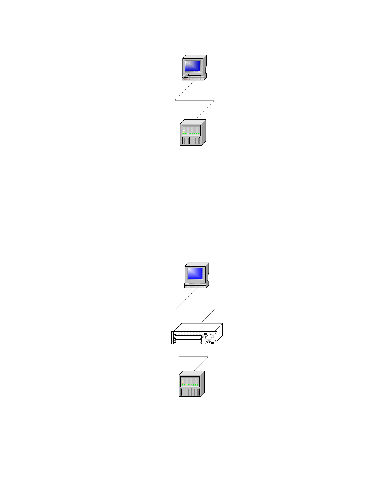
A typical automation system consists of a SCADA system, located in a control center, which is
connected to devices located in the substation. The SCADA regularly polls the devices in order to
retrieve device readings and statuses. The operator uses the SCADA system to perform control
functions on selected devices.
Since it is the control system that initiates data acquisition and control, it is considered to be the
master system. Since the substation device responds to data acquisition and control requests, it is
considered the slave system.
SMP Gateway User Manual • 7
Page 22
SCADA
MASTER
SLAVE
DEVICE
Figure 1 Master and slave systems
2.1.2 Introducing the SMP Gateway in the Automation System
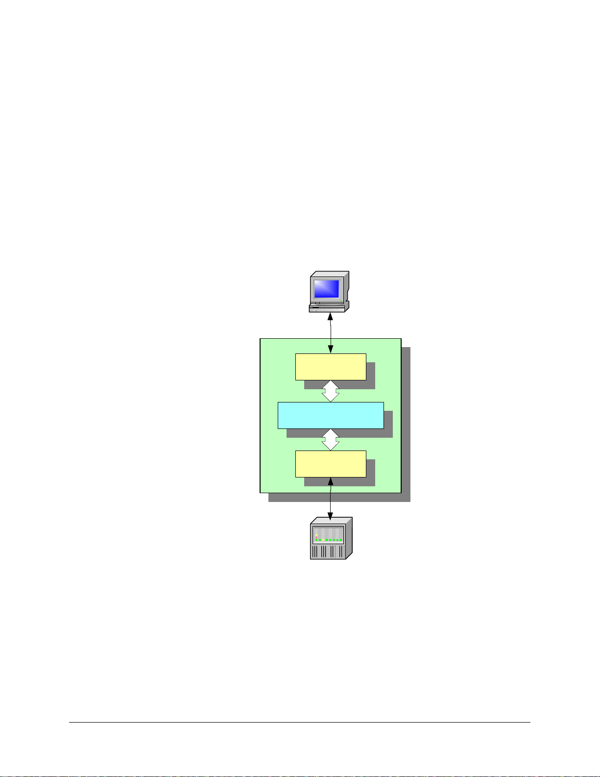
When an SMP Gateway is introduced in the automation system, it has to act as both a slave and a
master. The SCADA system interrogates the gateway as if it were a substation device. The
gateway is thus a slave to the SCADA. However, since the gateway is connected to the substation
devices, it must also be able to perform the functions of a master, such as polling for data and
sending control requests.
SCADA
MASTER
SLAVE
MASTER
SLAVE
DEVICE
Figure 2 The SMP Gateway as a Master-and-slave system
8 • SMP Gateway User Manual
Page 23
2.1.3 SMP Gateway Internals
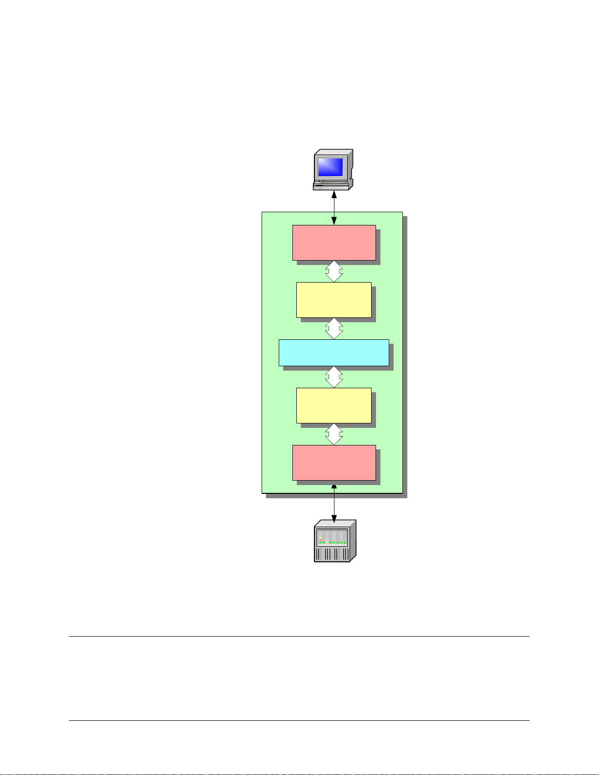
The SMP Gateway's internal architecture is based on a series of software components called
protocol components. Slave protocol components implement all the functions necessary to
process requests received from a SCADA or control center. Master protocol components
implement the functions necessary to poll devices and send control requests. Cooper Power
Systems provides components for most standard protocols, such as DNP3, MODBUS, IEC-608705-101/103/104 and IEC 61850, as well as a large number of proprietary protoc ols such as SEL,
ABB TEN BYTE, Motorola MDAC, and more.
The master protocol component polls the device and stores the data that it retrieves in an internal
database, called the Real-Time Data Exchange (RTDX). The RTDX is much more than a simple
data store. Besides storing the current value of all the device data points, it also stores the different
types of information than can be provided by a substation dev ice, such as the quality and
timestamp of the data. It also stores information such as device tags used for control functions.
SCADA
SLAVE
PROTOCOL
REAL-TIME
DATA EXCHANGE
MASTER
PROTOCOL
DEVICE
Figure 3 The SMP Gateway real-time data exchange
2.1.4 Communications Components
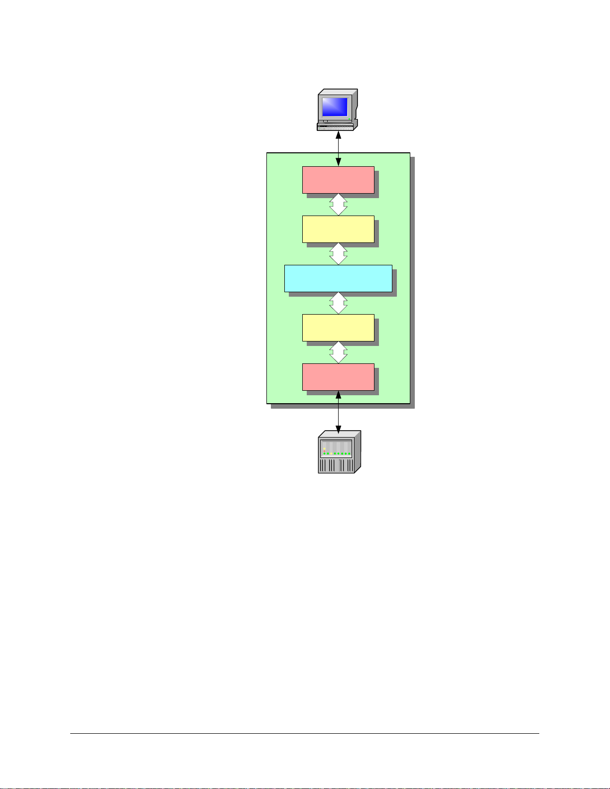
SMP Gateway protocol components process the messages exchanged among the control centers
and the devices. However, these messages can be transmitted using various communications
methods. For instance, the MODBUS protocol can be used on a TCP/IP network or on an RS-232
serial link.
SMP Gateway User Manual • 9
Page 24
SMP Gateway communications components implement all the functions required to communicate
with a device or control center using a variety of communications technologies. Cooper Power
Systems provides communications components for asynchronous serial ports, RS-232, RS-422,
RS-485, TCP/IP and modems.
SCADA
SLAVE
COMMUNICATION
COMPONENT
SLAVE
PROTOCOL
COMPONENT
REAL-TIME
DATA EXCHANGE
MASTER
PROTOCOL
COMPONENT
MASTER
COMMUNICATION
COMPONENT
DEVICE
Figure 4 SMP Gateway communications components
2.2 Configuring the SMP Gateway
The SMP Gateway configuration process consists of establishing the relationships among the
internal components, and providing the specific settings for each of these components. This task is
10 • SMP Gateway User Manual
Page 25

greatly simplified by Cybectec SMP Tools family of software programs. These Windows-based
programs help you configure your SMP Gateway and identify and correct any problems.
The configuration process consists of the following steps:
Identifying the SMP Gateway model and the installed options.
Creating a master protocol component for each device that is connected to the SMP Gateway.
Defining all the data points in the device.
Defining the communications link to be used to connect the device to the SMP Gateway.
Creating a slave protocol component for each SCADA or control center.
Defining the data points that the SMP Gateway will report to the SCADA.
Defining the communications link to be used to connect to the SCADA.
Adding a firewall and optionally a security ser ver that supports corporate network users.
Thus, the configuration settings define the functions that the SMP Gateway performs. These
settings are stored in a file that you load onto the gateway. The flexibility of the SMP Gateway
architecture is the basis of Cooper Power Systems’ step-by-step substation modernization strategy.
In the following sections, we will show you how you can configure the SMP Gateway to perform
all the functions required of a substation gateway.
2.2.1 The Transparent SMP Gateway
As a first step in a substation automation project, you can easily set up the SMP Gateway to act as
a transparent interface between the SCADA and a substation device. The following diagram
illustrates how you can do this using the MODBUS protocol.
SMP Gateway User Manual • 11
Page 26
SCADA
RS-232
CONNECTION
MODBUS
SLAVE
REAL-TIME
DATA EXCHANGE
MODBUS
MASTER
RS-232
CONNECTION
DEVICE
Figure 5 The transparent SMP Gateway
In this configuration, the master component polls the device and stores the values in the RTDX.
The slave component processes the SCADA polling requests and sends the values provided by the
device.
There is not much use for a transparent gateway. However, it contains much more than the
components that we described previously. Simply by adding the SMP Gateway to the substation,
you now have access to the following advanced functions:
Centralized automation functions, using the built-in Automation functions or the IEC 61131-3
Soft PLC logic processor.
Real-time data display, using the built-in web server.
Transparent access to devices, using the passthrough server, for local or remote IED
maintenance.
12 • SMP Gateway User Manual
Page 27
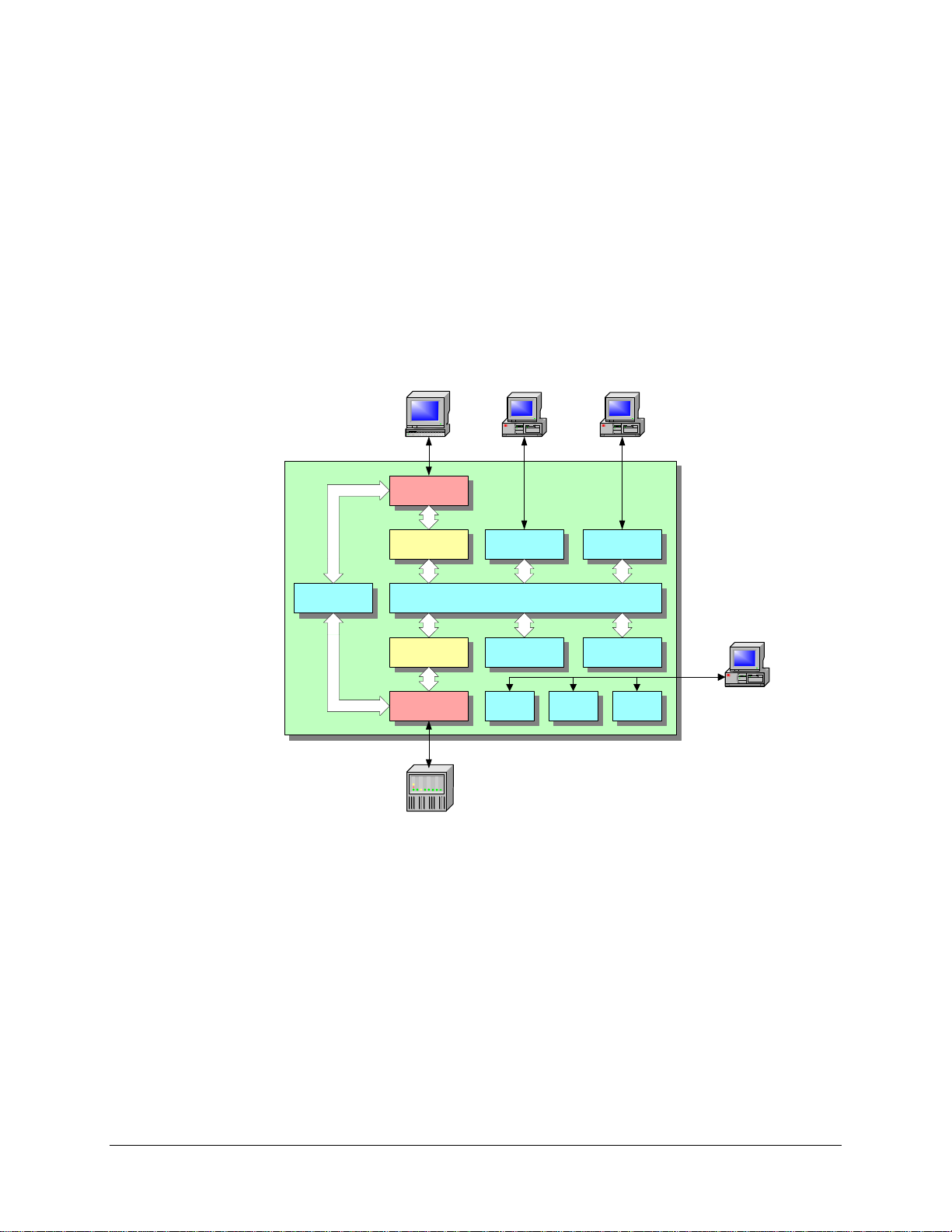
SNMP support to monitor communications status.
Sophisticated HMI, interactive diagrams, data logging and reporting, using Cooper Power
Systems’ Visual Substation software.
Sophisticated Windows tools for remote or local maintenance.
A sophisticated security server to support corporate network users.
Even more important, the transparent SMP Gateway is the first step in integrating new substation
devices to your existing SCADA and automation system.
PASSTHRU
SCADA
RS-232
CONNECTION
MODBUS
SLAVE
MODBUS
MASTER
RS-232
CONNECTION
INTERNET
EXPLORER
WEB
SERVER
REAL-TIME
DATA EXCHANGE
IEC 1131
SOFT PLC
STATS LOGS TRACES
VISUAL
SUBSTATION
HMI
VISUAL
SUBSTATION
SNMP
MAINTENANCE
TOOLS
DEVICE
Figure 6 Additional SMP Gateway functions
2.2.2 Using the SMP Gateway as a Protocol Translator
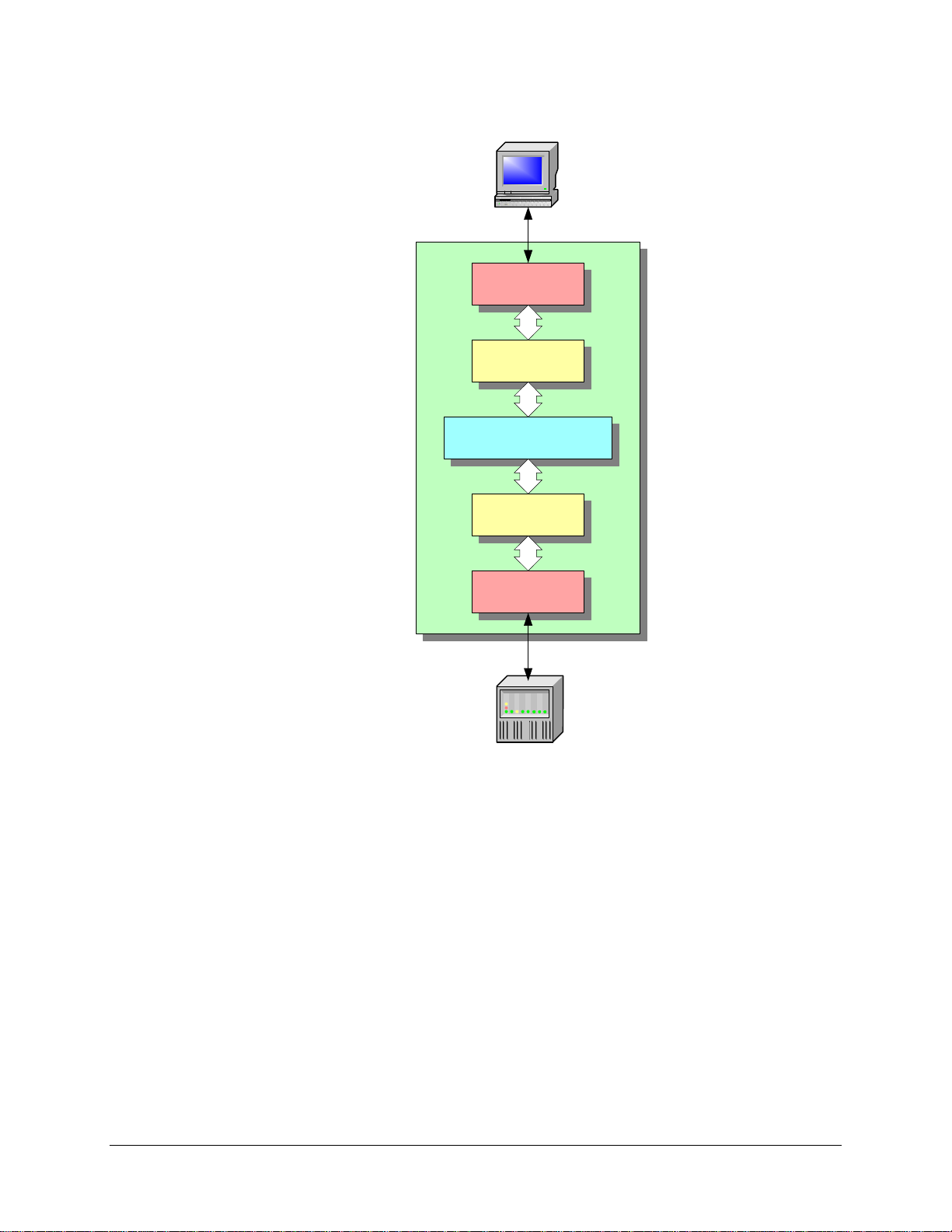
As we saw in the last section, the SMP Gateway is transparent when the master and slave
protocols are the same. When you configure different master and slave protocols, the
SMP Gateway becomes a protocol translator.
Since you can independently configure the communications links for the master and slave
components, you can easily use the SMP Gateway to integrate legacy serial devices in a modern
network environment. Similarly, you can connect modern IEDs to a legacy control center.
SMP Gateway User Manual • 13
Page 28
SCADA
TCP/IP
CONNECTION
DNP3
SLAVE
REAL-TIME
DATA EXCHANGE
MODBUS
MASTER
RS-232
CONNECTION
DEVICE
Figure 7 The SMP Gateway protocol translator
2.2.3 Using the SMP Gateway as a Data Concentrator or Device Multiplexer
The SMP Gateway architecture is designed to simultaneously support any number of master
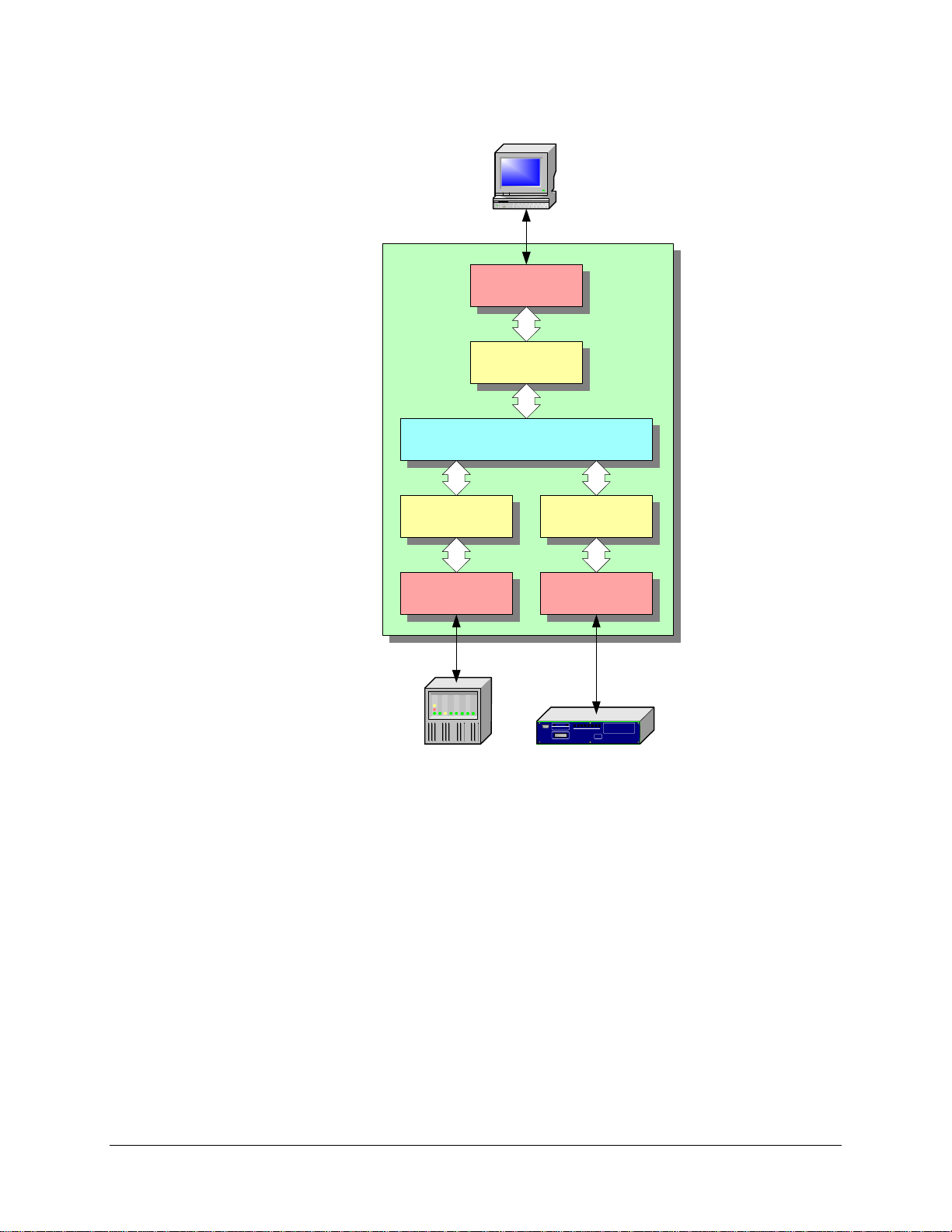
components. Each component has its own communications link and its own protocol. All the data
retrieved from the devices is stored in the RTDX, where it becomes available to the SCADA.
Using the SMP Gateway as a data concentrator is a simple matter of configuration, and it provides
a highly efficient means of adding new devices to an existing automation system. The SCADA
system has no knowledge of the new devices; it only sees new data points.
14 • SMP Gateway User Manual
Page 29
SCADA
TCP/IP
CONNECTION
DNP3
SLAVE
REAL-TIME
DATA EXCHANGE
MODBUS
MASTER
RS-232
CONNECTION
DEVICE DEVICE
SEL
MASTER
RS-232
CONNECTION
Figure 8 The SMP Gateway data concentrator
2.2.4 Using the SMP Gateway as a Communications Processor
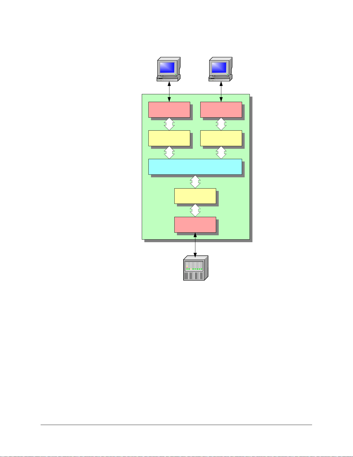
The SMP Gateway architecture supports any number of slave components. Each component has
its own communications link, and all the device data can be sent to any number of SCADA and
control centers, each with its own protocol. Using the SMP Gateway, sending data to a new
control center is a simple matter of configuration.
SMP Gateway User Manual • 15
Page 30
SCADA
MAINTENANCE
CENTER
RS-232
CONNECTION
MODBUS
SLAVE
DATA EXCHANGE
CONNECTION
TCP/IP
CONNECTION
DNP3
SLAVE
REAL-TIME
MODBUS
MASTER
RS-232
DEVICE
Figure 9 The SMP Gateway as a communications processor
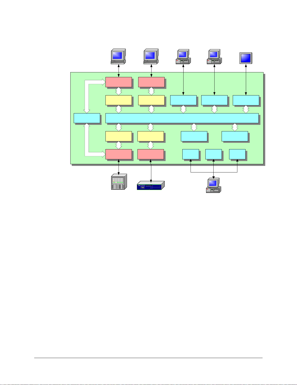
2.2.5 Putting it all Together
The SMP Gateway’s sophisticated architecture allows it to integrate existing and new RTUs,
IEDs, PLCs and control centers into a single homogeneous substation automation system. It
provides you with a complete solution for automating new substations and modernizing legacy
systems.
16 • SMP Gateway User Manual
Page 31
SCADA
SCADA
INTERNET
EXPLORER
VISUAL
SUBSTATION
HMI
TOUCH
SCREEN
PASSTHRU
RS-232
CONNECTION
MODBUS
SLAVE
MODBUS
MASTER
RS-232
CONNECTION
DEVICE
Figure 10 The substation SMP Gateway
TCP/IP
CONNECTION
DNP3
SLAVE
SEL
MASTER
RS-232
CONNECTION
DEVICE
WEB
SERVER
REAL-TIME
DATA EXCHANGE
VISUAL
SUBSTATION
IEC 1131
SOFT PLC
STATS LOGS TRACES
MAINTENANCE
TOOLS
LOCAL HMI
SNMP
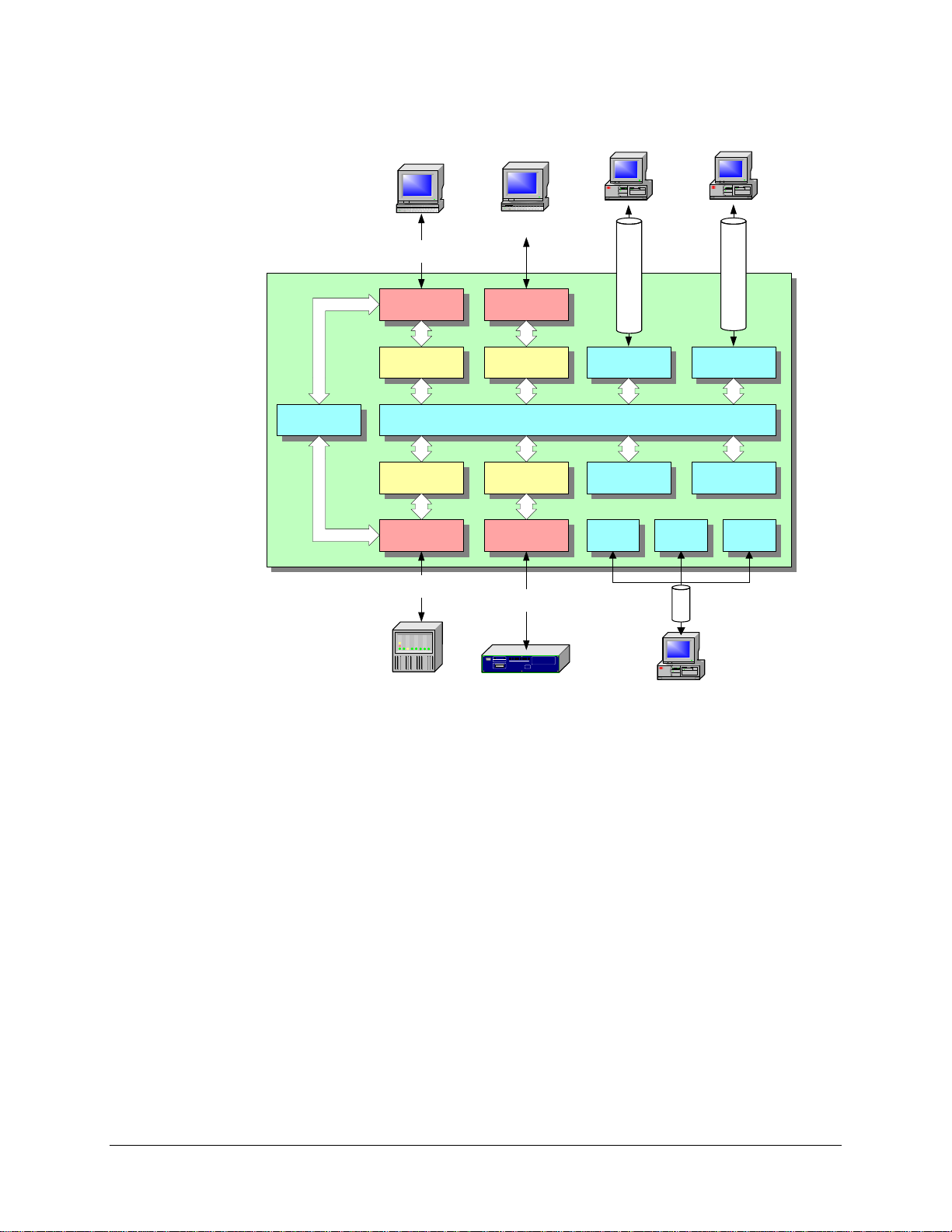
2.2.6 Securing the Substation
Widespread data access within the SMP Gateway can become an important security risk if it is
compromised, but it can also become a security asset. This is why SMP Gateways are ready for
NERC CIP-002-1 to CIP-009-1 Cyber Security Standards. The gateway provides a single point of
access to all substation data. The security features of the SMP Gateway allow you to protect the
substation devices (see Figure 11).
ou activate the security features within your substation SMP Gateway, you will be able to:
If y
comply with authentication and authorization policies;
set up a firewall to protect from substation LAN security breaches;
monitor and lock out remote connections.
File integrity check is also periodically performed on the SMP Gateway files.
The access inside the firewall protection has additional layers of protection, so that only a few
users of your choice will have the possibility to modify parameters inside the substation.
SMP Gateway User Manual • 17
Page 32
FIREWALL PROTECTION
SCADA
HARD-WIRE
CONNECTION
SCADA
SPECIFIC IP
ADDRESS OPEN PORT
INTERNET EXPLORER
VISUAL
SUBSTATION
HMI
VPNVPN
PASSTHRU
RS-232
CONNECTION
MODBUS
SLAVE
MODBUS
MASTER
RS-232
CONNECTION
HARD-WIRE
CONNECTION
DEVICE
TCP/IP
CONNECTION
DNP3
SLAVE
DATA EXCHANGE
SEL
MASTER
RS-232
CONNECTION
HARD-WIRE
CONNECTION
DEVICE
WEB
SERVER
REAL-TIME
IEC 1131
SOFT PLC
STATS LOGS TRACES
MAINTENANCE
VPN
TOOLS
VISUAL
SUBSTATION
SNMP
Figure 11 The SMP Gateway with a firewa ll
In the following chapters, we will learn how to configure the SMP Gateway to perform these
functions.
18 • SMP Gateway User Manual
Page 33

3 SMP Tools Overview
To assist you with the tasks you will want to perform with the SMP Gateway s in your
organization, we have provided you wi t h o ur suit e of SMP Tools.
The SMP Tools are Microsoft Windows-based programs that make it easy for you to configure
the SMP Gateway and perform maintenance functions. They run on a PC, are simple to use, and
provide advanced features that allow you to rapidly configure all the devices and communications
links in your substation. They can be used locally or remotely through a LAN, WAN or VPN.
When security is activated, users must log in before they can use any function.
The Cybectec SMP Tools include the following applications:
SMP Manager
Manages all the SMP Gateways in your organization. It displays the state of each gateway,
manages their configuration files and local security database, allows you to group two
gateways together to achieve redundancy, and is used to invoke the configuration and
maintenance tools for any gateway to which it is connected. From SMP Manager, you can
also start Internet Explorer to view the data points, logs and traces in real time, and you can
start a Telnet session in order to set-up certain advanced features such as dial-up access or
IRIG-B signal output type.
SMP Config
Used to configure the SMP Gateway. It has a spreadsheet-like grid that you use to specify the
devices and control centers connected to the gateway, their protocols, their communications
links and their data points. Advanced editing functions make it easy for you to enter the data
points. Template editing allows you to pre-define standard devices with standard data points,
thereby reducing labor intensity and the possibility of erro rs.
61850 Config
Used to configure the IEC 61850 and UCA 2.0 protocols on the SMP Gateway.
SMP Log
Used to browse through and manage the log files maintained by the SMP Gateway. All
significant events are logged, including local and remote control events, system failures,
special protocol events, and so on.
SMP Stats
Used to browse through and manage a large variety of dynamically updated statistics, ranging
from full communications statistics for each link to the processor load for each protocol
component.
SMP Gateway User Manual • 19
Page 34

SMP Trace
Used to browse through the real-time traces generated by the SMP Gateway. SMP Trace can
display detailed traces of all protocol and communications link activity. Traces are displayed
in both hexadecimal and application protocol format. The tracing functions are similar to
those usually provided by protocol analyzers, with the notable exception that they can be used
remotely at any time on any SMP Gateway and that they decode information at the
application level. As such, they constitute an excellent commissionin g or debugging tool.
SMP Connect
Used to establish passthrough connections with any IED connected to an SMP Ga teway, for
the purpose of doing remote configuration and mai ntenance of IEDs using manufacturerprovided software.
SMP Loader
Used with the SMP 4-20 and SMP 8-40 to load new versions of most of the SMP Gateway
firmware components, and with the SMP 4, SMP 16/CP and SMP 16/SG, to load the
secondary bootstrap program. Refer to Appendix A and to your SMP G ateway installation
guide for details on using SMP Loader.
Event Translator.
Used to convert Cybectec event files to the COMTRADE format.
The next chapter will discuss how to create a list of SMP Gateways with SMP Manager, and will
then explain how to do a complete configuration of your SMP Gateway using SMP Config.
20 • SMP Gateway User Manual
Page 35
4 SMP Manager
SMP Manager is the doorway to your SMP Gateways. It runs on your PC, as do all the tools you
launch through SMP Manager. You are already familiar with the application, since you added
your new gateway to the list of SMP Gateways managed by SMP Manager when you installed
your SMP Gateway. This section goes over a few of the points that were covered in your
SMP Gateway installation guide, and provides additional information.
4.1 Starting SMP Manager and Logging On
To start SMP Manager:
On the Windows taskbar, click Start.
Point to Programs, then Cybectec, and then SMP Tools.
In the SMP Tools menu, click SMP Manager.
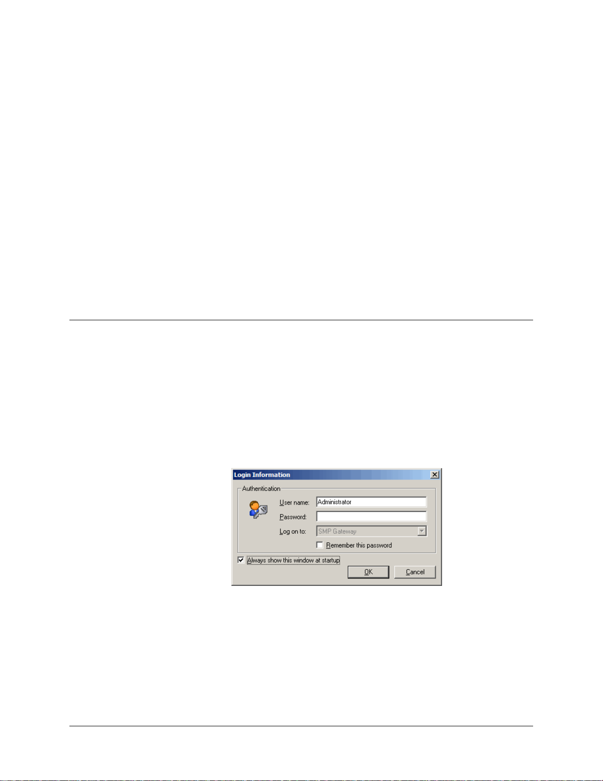
The SMP Manager main screen appears, followed by the Login Information dialog box.
If security has already been configured, enter valid credentials.
Click OK to close the dialog box.
SMP Gateway User Manual • 21
Page 36
4.2 Main Window
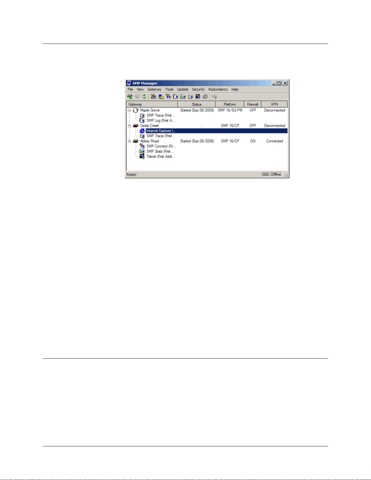
The following figure shows a typical SMP Manager window.
As illustrated, the main window displays information such as:
The list of SMP Gateways and the tools that are currently running for each gateway in the list.
The current status of each SMP Gateway in the list (started, failed, safe mode, max safe mode,
on standby, and various intermediate states).
The SMP Gateway model: SMP 4-20, SMP 8-40, SMP 4, SMP 16/CP or SMP 16/SG.
The IP address and redundancy status of any SMP Gateways you have grouped together for
the purpose of redundancy. This information is available only if your license supports
redundancy. This column is not available by default.
Whether the SMP Gateway's built-in firewall is active and whether VPN is connected or
disconnected.
This information is available only if your version of the SMP Gateway software supports the
SMP Gateway’s security features. The firewall information is not available by default
You can choose which columns you want to display and their order of appearance, with a right
click on the column header.
4.3 Adding an SMP Gateway
Creating a list of the SMP Gateways you want to monitor is easy. Proceed as follows for each
gateway you want to add to the list:
From SMP Manager’s File menu, click Add SMP Gateway to add your SMP Gateway to
the list.
The Gateway Properties dialog box appears.
22 • SMP Gateway User Manual
Page 37

Type the name by which you want to identify your SMP Gateway in Gateway Name. The
Configuration file is the file that will be opened by default in SMP Config. If you change its
name afterwards through the File menu, you must come back to this dialog box and change
the name in the Configuration File text box, so it opens the right file at startup.
In the First Address box, type the IP address of the first Ethernet port. You can also type the
address of the second Ethernet port in the Second Address box, although it is not necessary to
do so.
If the SMP Gateway cannot be directly accessed through the network, but requires a dialup
connection, select the The gateway is connected over a remote dial-up checkbox to prevent
SMP Manager from polling the gateway for its status.
Click Add.
The SMP Gateway gets added to the list, and SMP Manager automatically detects the gateway
model and in the case of an SMP 4, whether an internal modem is installed.
4.4 Information Provided by the SMP Gateway Icon
The SMP Gateway icon, which is displayed beside each gateway name, provides additional
information about the SMP Gateway.
The following table gives the meaning of each icon:
Icon Description
A device with two red LEDs.
SMP Manager is unable to establish a connection with the gateway.
A device with flashing yellow and green LEDs.
SMP Manager is connected to the gateway.
A blank page.
A file (configuration file, new software, etc.) has been modified and will be activated
SMP Gateway User Manual • 23
Page 38
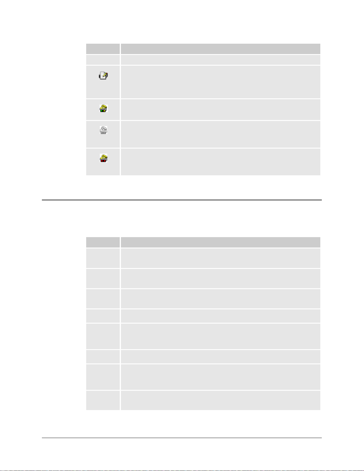
Icon Description
when the gateway is restarted.
A lined page and a pencil.
A report is currently in progress.
The report file provides detailed information about the gateway. You should, therefore,
send an SMP Gateway report file with any request for technical support.
A device, flashing yellow and green LEDs and a yellow telephone.
SMP Manager is connected to the gateway via remote dialup.
A device and a telephone, grayed.
The gateway is configured for remote dialup but not currently connected to SMP
Manager.
A device, red LEDs and a yellow telephone.
SMP Manager is unable to establish a connection with the gateway over the remote
dialup connection.
4.5 Customizing the Display
You can customize the display in the SMP Manager window to suit your needs. You can choose
which columns you want to display, and the order in which you want them to appear.
Column Description
Gateway The list of SMP Gateways and, if you request it, the tools that are currently running for
each gateway in the list.
IP Address The IP address of any SMP Gateways you have grouped together in SMP Manager. This
column is not available by default.
Status The current status of each SMP Gateway in the list (started, failed, safe mode, max safe
mode, on standby, and various intermediate states).
Platform The SMP Gateway model: SMP 4-20, SMP 8-40, SMP 4, SMP 16/CP or SMP 16/SG.
Firewall Whether the SMP Gateway's built-in firewall is active. This information is available only
if your version of the SMP Gateway software supports the SMP Gateway’s security
features.
VPN Indicates if the SMP Gateway is connected to SMP Manager using VPN or not.
Group This column shows the virtual address given to the redundancy group. If the address is
modified, the new address will appear beside the old one, separated by an arrow. Upon
the next reboot, the device will be grouped under the new address only.
Security This column shows whether the security is activated or not, if it is global or local, and
how recent it is.
24 • SMP Gateway User Manual
Page 39

4.5.1 Adding or Removing a Column
To toggle between displaying a column and removing it from the display:
Right-click any column heading.
In the shortcut menu, locate the column you are interested in.
Put or remove a checkmark to add or remove the column to or from the display.
4.5.2 Changing the Position of a Column
To change the order of a column in the display:
Click the column heading of the column you want to relocate.
Drag the heading to the target location.
SMP Gateway User Manual • 25
Page 40

Page 41

5 Configuring the
SMP Gateway
As we saw under “Principles of Operation”, you have to configure the SMP Gateway before you
can use it. For this, you use SMP Config to define the characteristics of your SMP Gateway and
the functions it has to perform. The configuration is stored in a file that is then loaded onto the
SMP, where it is stored in non-volatile flash memory.
Using SMP Config, you will perform the following configuration steps:
For an SMP 4-20, an SMP 8-40 or an SMP 16/SG, define the hardware options installed.
Create a master protocol instance for each device to be supported.
Define each data point on each device.
Configure the communications link to be used to connect to each device.
Create a slave protocol instance for each SCADA or control center.
Configure the communications link to be used to connect to the SCADA.
Map the device data points to SCADA data points.
You will then use SMP Manager to send the configuration file to the SMP.
Note: There can only be one instance of SMP Config running at any given time.
If you launch the tool for a given SMP Gateway and then launch it again for a
second SMP Gateway, SMP Config will prompt you to save any change s you
have made, close the configuration file of the first gateway, and then open the
configuration file of the second gateway.
To create a configuration file for your SMP Gateway, proceed as follows:
Start SMP Manager.
In SMP Manager’s application window, select your SMP Gateway.
SMP Gateway User Manual • 27
Page 42
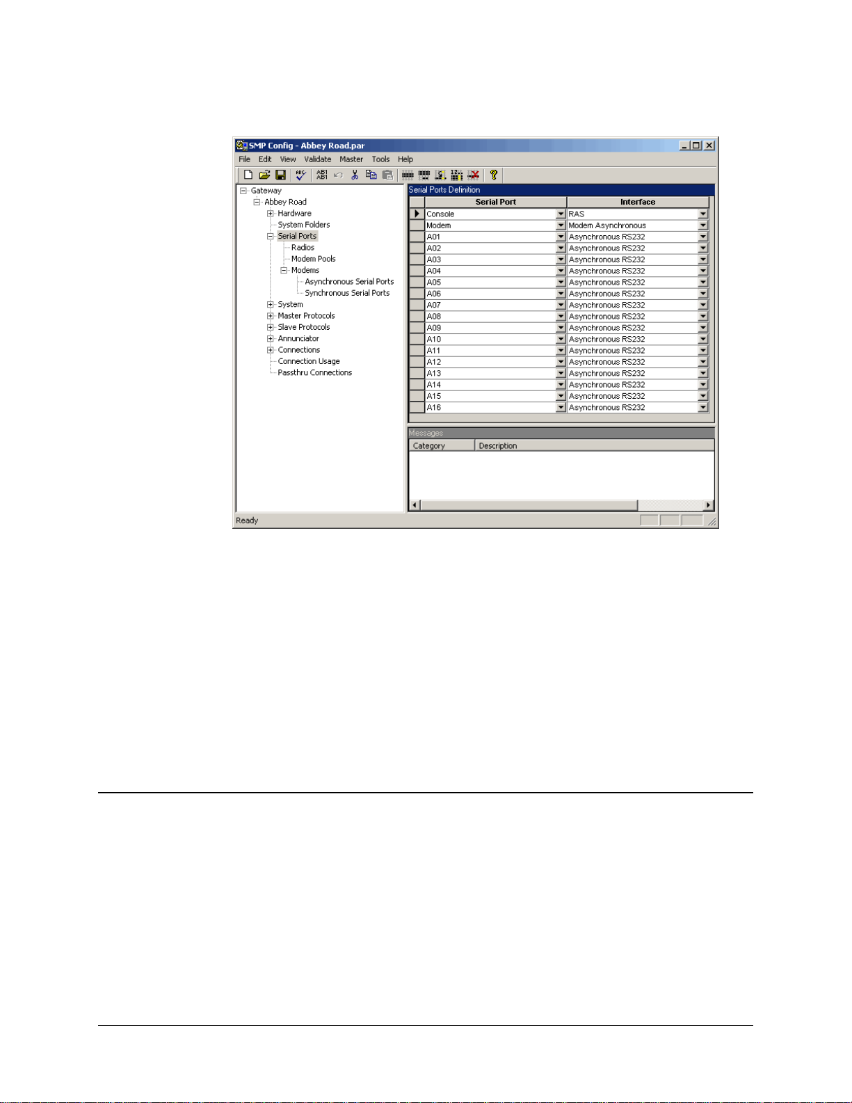
In the Tools menu, click SMP Config to start the application.
The SMP Config display includes 3 panes. The left pane is a tree structure of all the configuration
topics. The top right pane displays the settings for the topic you have selected in the left pane. The
bottom right pane appears when your request that the configuration be validated; it displays error
and warning messages.
The gateway name is the name you assigned when you added the SMP Gateway in SMP
Manager. The configuration file name on the title bar was also assigned when you added the
SMP Gateway in SMP Manager.
If you open the Master Protocols and Slave Protocols branches, you will see that the tree
structure offers you a fixed set of protocols. These are the protocols currently supported by your
product license.
5.1 Creating Master Protocol Instances
You need to add a master protocol instance for each device you want to access with your
SMP Gateway (see Figure 2). Even if a number of devices share a multidrop link, each of them
requires
when communicating with the device, which is why it requires a master protocol instance.
There are two ways to add the master protocol instance:
its own master protocol instance. Each device is a slave, so the gateway acts as a master
You can use a template, which eases the task of configuring the master protocol instance, by
automatically entering the points list for the device. SMP Config provides templates for a
number of common substation devices.
28 • SMP Gateway User Manual
Page 43
If no template is available, you will need to enter the points list. If you are configuring a
number of devices of the same type, you can save the first device configuration as a template
that you will then use to configure the other devices.
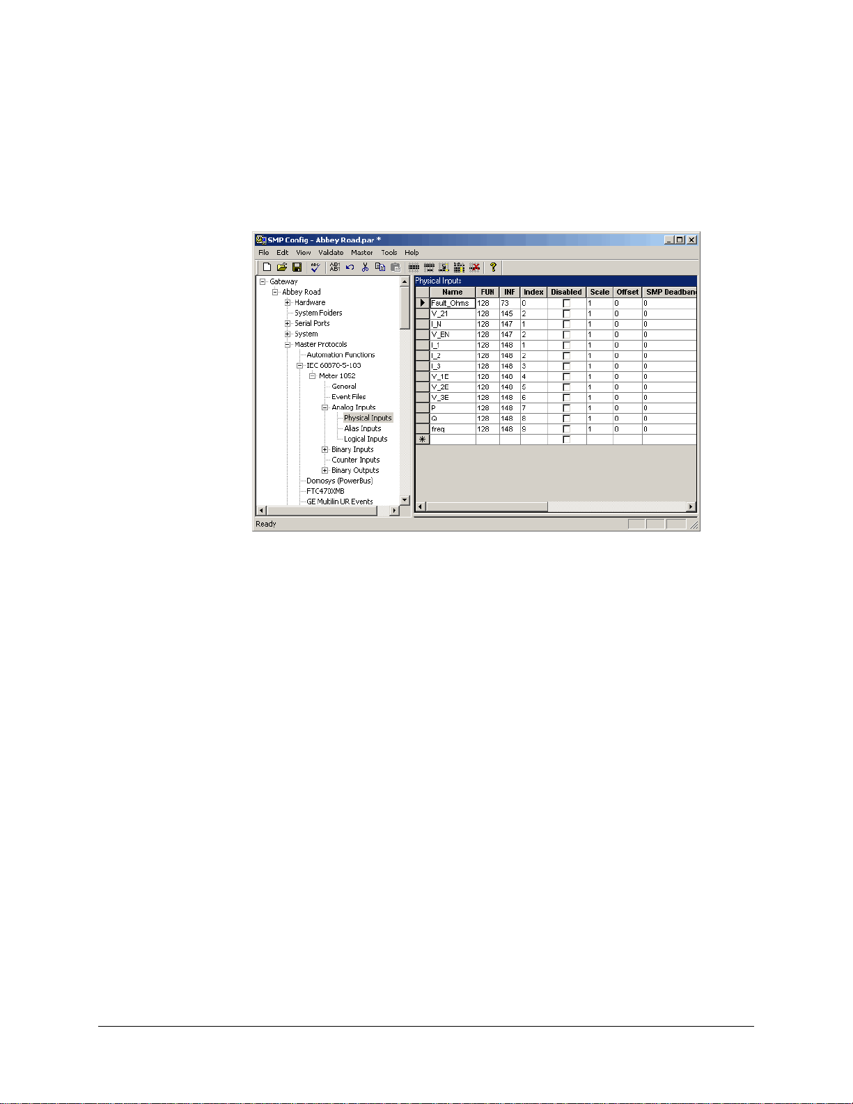
Once you have added a master protocol instance and entered its data points (manually or via a
template), you can click a particular data point type in the left pane and see the list of data points
and their settings in the right pane, as shown next.
5.1.1 Creating a Master Protocol Instance from a Template
To add a master protocol instance from a template:
In the left pane, open the Master Protocols branch, to display the list of master protocols
provided under your product license.
In the left pane, click the protocol for which you want to add an instance.
The list of all defined master protocol instances appears in the right pane.
In the Tools menu, click New Instance From Template.
Choose the appropriate template, and click Open.
In the dialog box, enter:
The name of the new instance.
The device prefix.
The device prefix is a string that identifies the device and is used as a prefix for all of its
data point names. The prefix ensures that every name in the system is unique. An
explanation of the usage of prefixes is provided under “Configuring the Master Protocol
eral Settings”, in the next sections.
Gen
The new instance appears in the left pane. If you open its tree structure and click the various
physical data point types, all the data points supported by the device will be displayed in the right
pane.
SMP Gateway User Manual • 29
Page 44

5.1.2 Creating a Master Protocol Instance Manually
To add a master protocol instance manually:
In the left pane, open the Master Protocols branch, to display the list of master protocols
provided under your product license.
In the left pane, click the protocol for which you want to add an instance.
The list of all defined master protocol instances appears in the right pane.
In the right pane, type the name of the new instance at the end of the list of names, and press
the Tab key on your keyboard.
The new protocol instance is added in the left pane, under the protocol type you had selected. If
you expand its tree branch and click an item, the corresponding protocol settings will be displayed
in the right pane. Note that if you click a physical data point type in the left pane, the right pane
will display an empty row since you will have to add the physical data points manually.
5.1.3 Configuring the Master Protocol General Settings
All master protocol components share common settings that define how they interact with a
device. The following procedure describes how to enter these settings. If you created the protocol
instance from a template, the general settings have been defined for you. However, you should
verify the settings to make sure they match your device configuration, and you should familiarize
yourself with the naming conventions discussed in this section.
In the left pane, click General to display the list of general setting s for the selected protocol.
In the right pane, type a Device Prefix.
The string you enter will be used as a prefix for all the I/O point names of the device. It is
mandatory for each instance of a protocol. It is used to distinguish data point names that are
on the same device type, but on multiple physical devices. The device prefix ensures that
every data point name in the system is unique. Device prefixes are described in the following
section, “Adding Data Points from a Protocol Template”.
Device prefi
x and naming conventions
A typical substation automation project requires the configuration of thousands of data points.
You can significantly reduce the effort by carefully planning how to name devices and data points.
Cybectec tools provide additional functionality if the names of data points are based on so me type
of convention. For our engineering projects, we use a naming convention such as the following:
A data source name, such as the substation name: MAPLE, CEDAR.
A voltage level: 220 or 25.
A device name: L1 to indicate a line, T1 to indicate a transformer, F1 to indicate a feeder,
BUS for a bus bar.
A signal name: V_phsA_mag to indicate the phase A voltage magnitude, A_phsA_mag to
indicate the phase A current magnitude, Pos_st to indicate the status of a breaker or a line
switch.
30 • SMP Gateway User Manual
Page 45

With such a convention, a data point called CEDAR_220_BUS_V_phsA_mag clearly
indicates the voltage magnitude of phase A on the 220 kV bus of the CEDAR substation. A data
point called MAPLE_025_F1_Pos_st indicates the status of the breaker switch of feeder 1 at
the MAPLE substation.
Still in the General settings, enter the scanning settings.
For instance, to configure a MODBUS master protocol, you would provide settings such as
the following:
A Device Address, typically 1.
A MODBUS Type, typically RTU Serial.
A Scan Interval, typically 1000 ms.
A complete description of all settings is provided in the document entitled Master Protocol
Common Concepts. Protocol-specific settings are described in individual documents, such as
DNP3 Master Protocol.
5.1.3.1 Accessing Protocol-Specific Documentation
There are Cooper Power Systems documents available, to which you can refer for details on the
settings of the currently supported protocols.
To access the documents, proceed as follows:
Click Start, on the Windows taskbar.
Point to All Programs, then Cybectec, then SMP Tools, and then Documentation.
In the Documentation menu, click Protocols.
The list of available documents is displayed in an explorer window.
Click the document you want to read.
In the File menu of the explorer window, click Open with Acrobat.
Your Adobe Acrobat program starts up and displays the document in a window.
5.2 Configuring the Data Points
Once you have provided the general settings of the protocol component, you then enter all the data
points on the device. If you created the protocol instance from a template, all the data points have
already been added; however, we suggest you read this section for your information.
Protocol components typically support physical and logical data points of the following types:
Analog inputs
Binary inputs
Analog outputs
SMP Gateway User Manual • 31
Page 46

Binary outputs
A physical data point represents a real-life value, implemented on an external device. You need
to identify all the device data points, either manually or using a device template.
A logical data point is a value managed by the SMP Gateway. These data points are built-in and
cannot be modified, but they can be disabled.
Analog inputs are measured values. The system keeps 2 values for each analog measurement
obtained: a raw value, which is usually the value retrieved from the device, and a calculated value
expressed in engineering units, obtained using the following standard formula:
Engineering value = Raw Value X Scaling Factor + Offset
Binary inputs represent the state of a data point. The state is either ON or OFF.
Analog and binary outputs are typically initiated by a slave component, which sends a control
request originating from a control center, to the master component involved.
When you create a data point, you specify the type of data and you indicate how the
SMP Gateway will retrieve it. General properties such as name, type and units, are independent of
the type of device or protocol used. Protocol-specific properties indicate how the SMP Gateway
will retrieve the data from the device. Each protocol uses its particular form of addressing, such as
index values or data offsets.
For example, to add a data point for a MODBUS device:
Click the appropriate branch under the protocol instance.
In the right pane, type the name of the data point and fill in all the appropriate settings.
For instance, to define an analog input you would provide the following settings:
The name of the data point, such as BUS_VA. SMP Config will automatically add the
device prefix to this name, thereby generating the full name of the data point.
The input source, such as Input Registers.
The input format, such as Unsigned Integer.
The input size, such as 16 or 32 bits.
The word offset in the MODBUS device memory.
The scaling information required to convert the raw value to engineering units.
The Units and Description strings used to provide meaningful data displays.
A complete description of all settings is provided in the document entitled Master Protocol
Common Concepts. Protocol-specific settings are described in individual documents, such as
Modicon Modbus Master Protocol. A complete description of system data points can be found in
the section entitled “System Data Points” on page 231 of this manual.
To acces
Click Start, on the Windows taskbar.
s the various protocol documents:
Point to Programs, then Cybectec, then SMP Tools, and then Documentation.
In the Documentation menu, click Protocols.
32 • SMP Gateway User Manual
Page 47

5.2.1 Adding Data Points from a Protocol Template
Protocol templates can also be used to add points to a protocol component. For instance, you could
use a template to add the data points provided by an optional device feature. You can do this by
retrieving the data points from a protocol template.
To do this:
In the left pane, click the protocol instance to which you want to add the data points.
In the Tools menu, click New Points from Template.
A standard Windows “Open” dialog box appears.
In the Templates folder for the protocol type you selected, choose the “.tpl” file you want to
use, and click Open.
A dialog box appears, prompting you for the optional prefix and suffix to be added to every new
data point name. The upper portion of the dialog box provides information about the open
template file, while the lower portion shows warning and error messages.
Specify a prefix and a suffix, if applicable.
The new data points now appear in their respective categories under the selected protocol instance,
and their names contain the specified prefix and suffix.
Note that the prefix and suffix are not applied to logical data points, and that the logical data
points are reset every time you add data points from a protocol template. You should, therefore,
configure these data points once you have completed the list of physical data points.
5.3 Creating a Template from a Master Protocol Instance
You can create a template of a master protocol instance, which you can retrieve later in order to
quickly generate new protocol instances.
To create the template:
In the File menu, click Save As Template.
Choose the Templates folder in which you want to store the template, type a significant name
for the template file, and click Save.
Note that a template file can contain only one protocol instance. So if you want to create templates
for several protocol instances, create a new configuration for each one and save individual
templates.
SMP Gateway User Manual • 33
Page 48
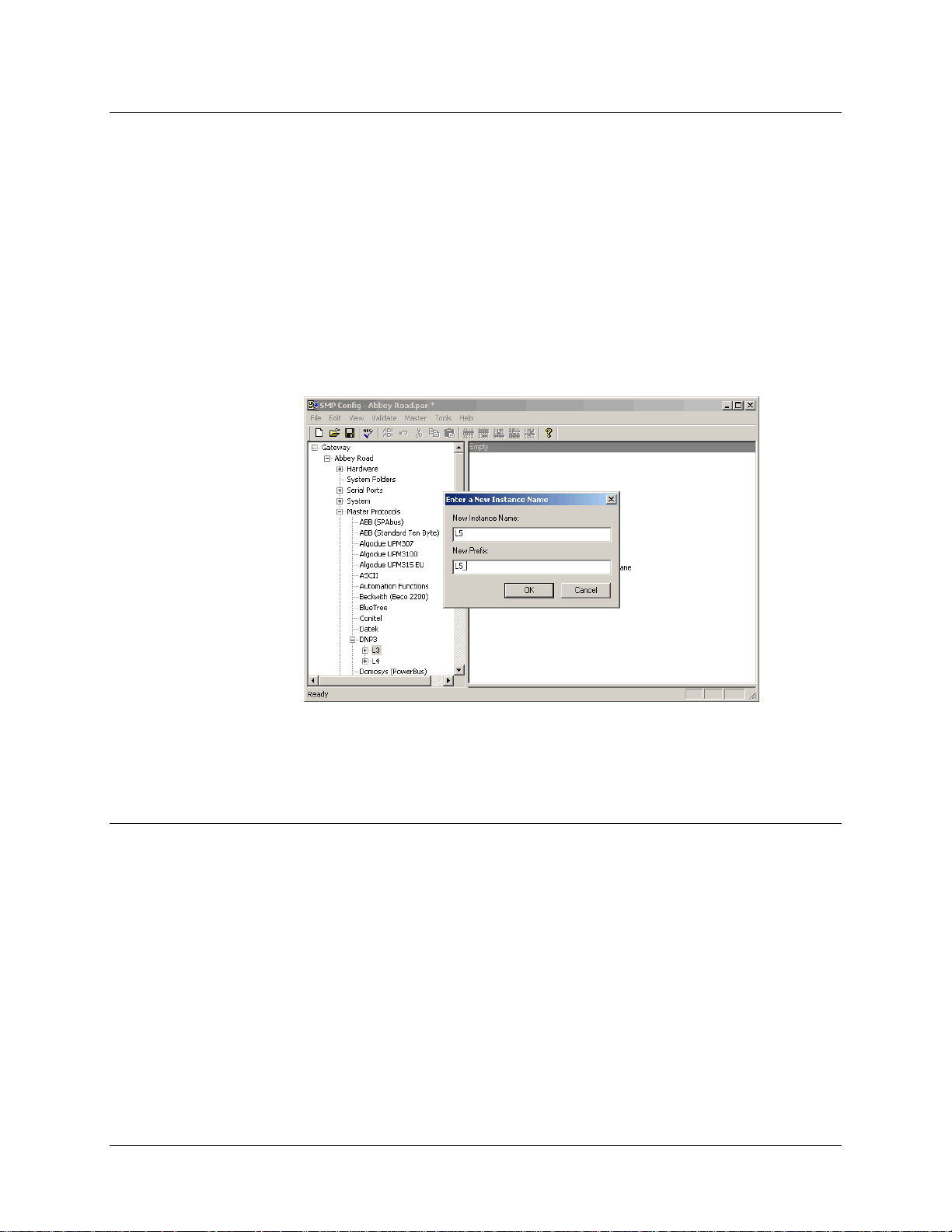
5.4 Duplicating a Master Protocol Instance
Once you have created a master protocol instance and configured its data points, you may want to
generate one or more additional instances with the same general and data point settings. A quick
way to accomplish this is by duplicating the master protocol instance.
To do this:
In the left pane, click the protocol instance you want to duplicate.
In the Tools menu, click Duplicate.
A dialog box appears, prompting you for the instance name and device prefix, as shown in the
following.
Type the name and prefix of the protocol instance, and click OK.
The new protocol instance now appears in the left pane.
5.5 Configuring the Communications Links
A protocol component communicates with a device or control center using one of the following: a
serial link, a modem or a TCP/IP network. The configuration of a communications component is
completely independent of the protocol used. Before you connect a device to the SMP Gateway,
you have to choose and configure its communications links.
5.5.1 Configuring the Serial Port Interfaces
Depending on the options you choose in the hardwa re configuration, you can configure the
SMP Gateway serial ports to support RS-232, RS-422 or RS-485 communication.
Click Serial Ports in the left pane, to display all the available ports.
34 • SMP Gateway User Manual
Page 49

For each port, choose the type of interface to be used. Most substation devices typically use
either Asynchronous RS-232 or Asynchronous RS-422/485. If you are using a serial port for
a touch screen, select ELO Touchscreen.
Serial port naming conventions
The SMP 16 provides 16 serial ports, identified as A01 through A16. It also has a modem port
labeled Modem, which has a “Modem Asynchronous” interface. The SMP 16/SG can also
house up to 2 additional serial ports boards, which will be identified as B01 to B16 and D01
to D16.
The SMP 4 and SMP 4-20 both provide 4 built-in serial ports. These ports are identified as
COM1 Board A through COM4 Board A.
The SMP 4 also provides a built-in console serial port. This port is identified as Built-in
Console 1 Board A. This feature allows you to use the Console port as a standard serial port.
If the SMP 4 has an internal modem, then it provides 3 built-in serial ports and 1 built-in
modem port. These ports are also identified as COM1 Board A through COM4 Board A;
however, the Interface column in the right pane indicates that the interface for COM4 Board
A is “Modem Asynchronous”.
The SMP 8-40 provides 4 additional ports named COM1 Board B through COM4 Board B.
The SMP 4-20 and SMP 8-40 SIOM use IPack modules to provide additional ports in groups
of 8. The ports in the first group are called IPack_A1 Board A through IPack_A8 Board A.
The ports in the second group are called IPack_B1 Board A through IPack_B8 Board A.
The SMP 8-40 supports two additional groups of ports called IPack_A1 Board B through
IPack_A8 Board B and IPack_B1 Board B to IPack_B8 Board B.
The purpose of each interface is given in the following table:
Interface Description
Asynchronous RS-232
Asynchronous RS-422/485
Modem Asynchronous
RAS (remote access server)
Use this value to indicate that the serial port is dedicated to establishing
a standard asynchronous RS-232 connection.
Use this value to indicate that the serial port is dedicated to establishing
an asynchronous RS-422 or RS-485 connection.
This value indicates that the port is used for modem asynchronous
communication. The value is automatically assigned to the Modem port
of an SMP 16 and to the COM4 Board A port of an SMP 4 equipped
with an internal modem.
Use this value to indicate that the serial port is configured to accept
incoming direct serial connections. This type of connection allows you
to use the SMP Tools as if you were connected to the SMP Gateway via
a normal network connection. By default, the console port is always
configured for RAS.
Refer to the SMP 4 Installation Guide, GUI-00316-00026 T, or to the
SMP 16 Installation Guide, GUI-00316-00032 T, for instructions on
setting up a RAS IP address pool. Then refer to “Erreur ! Résultat
incorrect pour une table.”, page 203, in the present manual, for the
step-by-step installation procedure.
SMP Gateway User Manual • 35
Page 50

Interface Description
Constraint for the SMP 4-20 and the SMP 8-40:
An SMP 4-20/SMP 8-40 CPU board can support up to 4 different bit
rates for the serial ports located on the front panel. This means that if
you specify that the console serial port is configured for RAS, only 3
other bit rates will be available for the remaining 4 serial ports on Board
A and that if all the other Board A serial ports are used, 2 of the 5 serial
ports must have the same bit rate. Note that if you set the console serial
port to Reserved and you do, in fact, accept incoming direct serial
connections on the console serial port as well as on the 4 remaining
serial ports, the SMP Gateway application will disable the console port
connection. This constraint obviously does not apply to Board B, since it
has 4 serial ports and there are 4 bit rates available.
Redundancy
ELO Touchscreen
Radio
Reserved
Use this value to indicate that the serial port is reserved for connecting
2 SMP Gateways together as a redundancy group. See “Grouping 2
SMP Gateways for Redundancy”, page 183.
Use this value to indicate that the touch input information of an Elo
touch screen will be transmitted to the SMP Gateway using a serial
cable, through this serial port.
Use this value to indicate that a radio will be connected to this serial
port.
Use this value to indicate that the serial port is reserved for purposes
other than those stated previously.
5.5.2 Configuring the Operation of the Serial Ports
Each serial port needs to be configured with the appropriate settings for the connected device.
In the left pane, open the Connections branch to display all the supported connection types.
Click Asynchronous Serial Ports to display the list of available ports.
Note that if you choose “Redundancy” as the interface for a serial port, this port will not
appear in the list of Asynchronous Serial Ports, as it will be reserved for connecting the
2 SMP Gateways that will be grouped together.
In the right pane, enter the settings for the selected serial ports.
The required settings are usually provided in the device manufacturer’s reference manual:
If you are using RS-485 2-wire communication, choose RS-485. If you are using RS-485
4-wire communication, choose RS-422.
Choose the device communications settings: baud rate, byte size, parity and number of
stop bits, such as 9600 baud, 8 bits, no parity, and 1 stop bit.
Choose the device hardware handshaking mode:
If the link type is RS-232, most devices do not use handshaking, so you should keep
the default values: RTS to Always On, DTR to Always On, and CTS to Ignore.
If the link type is RS-422, set RTS to Always On. You shouldn’t have any problem
if you keep the other default values: DTR to Always On, and CTS to Ignore.
36 • SMP Gateway User Manual
Page 51

If the link type is RS-485, set RTS to TX Request. You shouldn’t have any problem
if you keep the other default values: DTR to Always On, and CTS to Ignore.
If you are using RS-422 or RS-485 communication, specify whether or not you will be
using line terminators. Refer to your SMP Gateway installation guide for a discussion of
termination resistors.
5.5.3 Configuring TCP/IP Master Connections
TCP/IP connections are most often used by slave components to connect to control centers.
However, an increasing number of modern IEDs can be connected to a substation LAN using a
TCP/IP connection.
To configure a TCP/IP connection for a master protocol component:
In the left pane, click Connections, and then on TCP/IP Masters, to display the list of
defined connections.
In the right pane, enter the settings for the new TCP/IP connection in an empty row of the
grid:
Provide a significant name for the connection
If you are setting up an SMP 8-40, specify whether you will be using board A or board B
to interface with the network.
Enter the IP address of the device.
Enter the TCP port number of the device. This information is pro vided by the device
manufacturer.
5.6 Associating a Master Protocol Instance with a Communications Link
In the preceding steps, you configured a master protocol component and a communications
component. Now, you have to associate the protocol component with the communications
component.
SMP Gateway User Manual • 37
Page 52
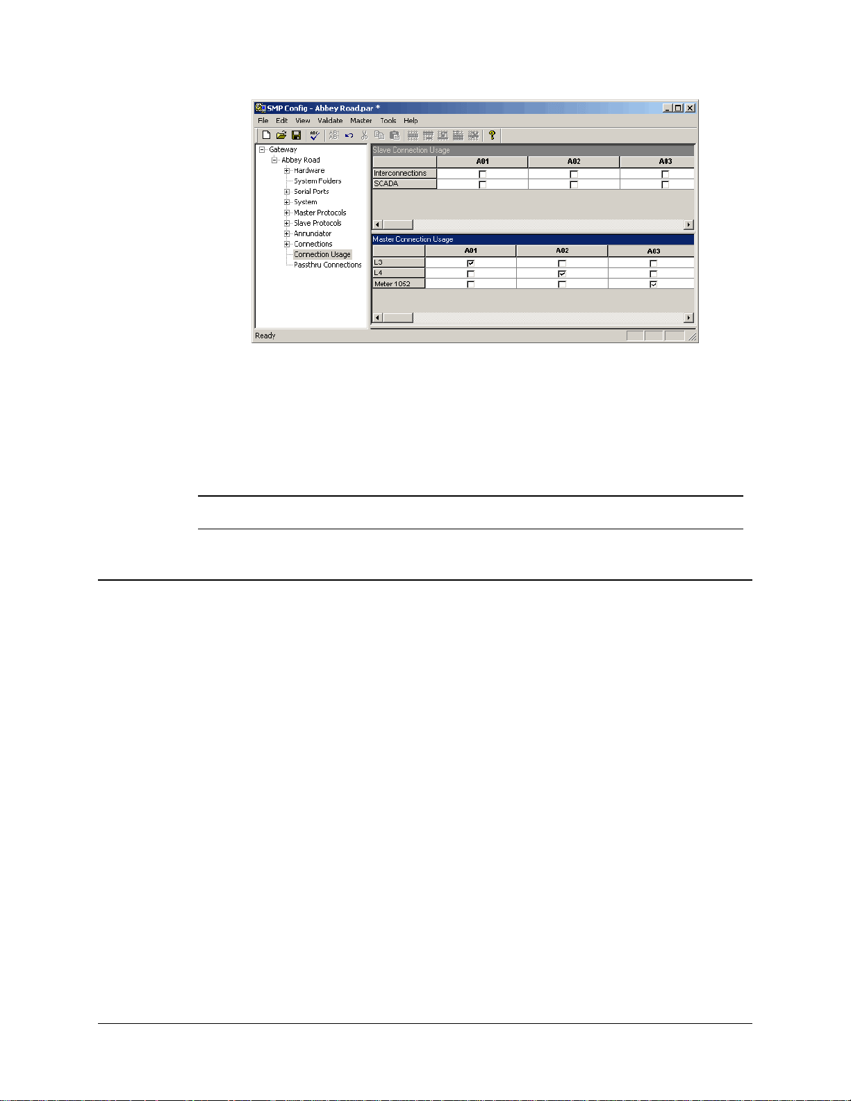
To associate a master protocol instance with a communications link:
In the left pane, click Connection Usage.
In the right pane, for each master protocol instance under Master Connection Usage, select
the checkbox under the appropriate connection instance.
Note: If you have several devices that share a multidrop link, each device must have a
different device address.
5.7 Testing the Configuration
Since the configuration of an SMP Gateway offers so many features, SMP Config tests and
validates the configuration files before you load it onto the gateway. Before going any further, you
should make sure your configuration is error-free. Then, you will send it to the gateway in order to
test it in a real-life situation.
5.7.1 Validating and Saving the Configuration
To validate the configuration:
In the Validate menu, click Validate All.
If your configuration contains any errors, messages will appear in the Messages pane, as shown
next.
Correct any errors and repeat the process until the configuration is error-free.
38 • SMP Gateway User Manual
Page 53
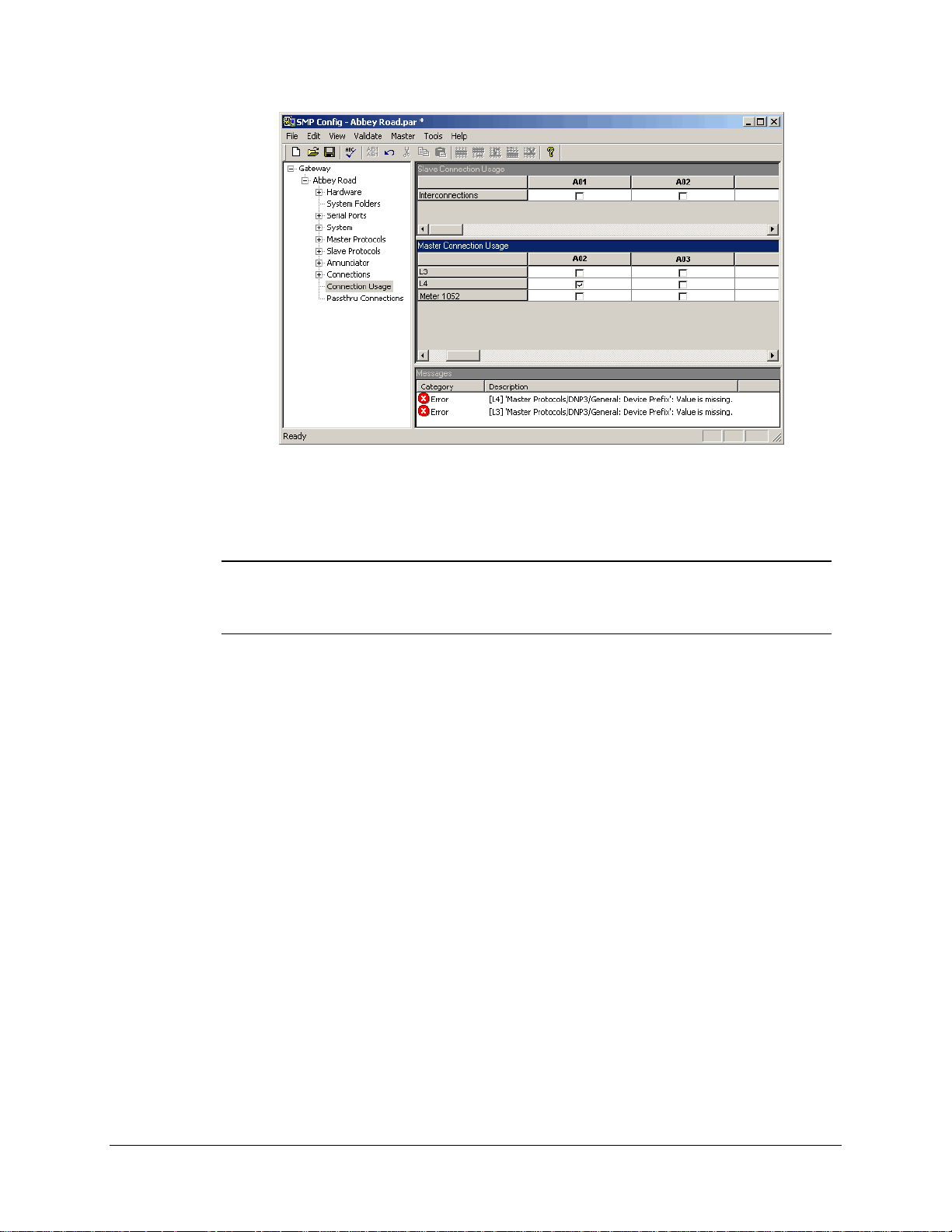
To save the configuration on your computer:
In the File menu, click Save.
Note: You cannot save a configuration file that contains errors. This feature is intended
to prevent you from inadvertently loading an invalid configuration file onto an
SMP Gateway. However, you can save your configuration file if the Messages
pane displays warnings only.
5.7.2 Sending the Configuration to the SMP Gateway
Once the configuration file is valid, you can send it to the SMP Gateway.
To do this:
Click your SMP Gateway in the SMP Manager application window.
In the Update menu, click Send Configuration File and choose your configuration file,
which has been saved in the location you specified in the Gateway Properties dialog box.
After sending the file to the SMP Gateway, SMP Manager informs you that you have to restart
your SMP Gateway for the new application to go into effect.
In the Restart Gateway dialog box, choose Shutdown and Restart to have the
SMP Gateway restart in normal mode.
All restarts are automatically logged in the SMP Gateway’s internal log file. You can type a
comment to indicate why you restarted the SMP Gateway. This comment will be added to the
event log.
SMP Gateway User Manual • 39
Page 54

The SMP Gateway will go through a series of startup steps, which will be displayed in the Status
column of your SMP Gateway. When startup is complete, if your configuration file is correct, the
Status column will show Started, to indicate that the gateway has started normally.
If your configuration file is incorrect, the Status column will indicate that there is a problem.
There are a number of conditions that can prevent the SMP Gateway from activating a
configuration. For instance, the hardware settings may not match the actual physical configuration
of the SMP Gateway. If the gateway does not start up normally, turn to “Troubleshooting”, page
247.
hat you have a working configuration file with all the master data points, you can use the
Now t
other SMP Tools and Internet Explor er to see what is going on with the SMP Gateway and with
the connected device.
5.7.3 Retrieving an SMP Gateway Configuration File
When you are about to send a configuration file to an SMP Gateway, as described previously, you
should first retrieve the old configuration file from the SMP Gateway and store it on your PC. This
will not be necessary when you first configure your SMP Gateway, but on subsequent updates, it
becomes an important precaution to take.
Proceed as follows:
Select the SMP Gateway in the list.
In the Update menu, click Get Configuration File.
In the Configuration Download dialog box, SMP Manager displays the available configuration
files. The current configuration file is identified by the “.par” suffix, while the previous
configuration file is identified by “.old”. You might also see files with the extension .txt and .ait.
Choose the .old file, and click the OK button.
In the Save As dialog box, specify the name and path where the configuration file is to be
stored. The name of the configuration file on the SMP Gateway is used as the default name.
5.8 Working with SMP Config
There are many time-saving features you can use to enter data in an SMP Config grid. These
features are presented next.
5.8.1 Selecting Cells and Lines
To select one or several cells:
Click the single cell you wish to select.
To select several cells, hold down the CTRL key while clicking the cells.
To select part of a column or part of a row, click the first cell, hold down SHIFT and click the
last cell you wish to select.
40 • SMP Gateway User Manual
Page 55
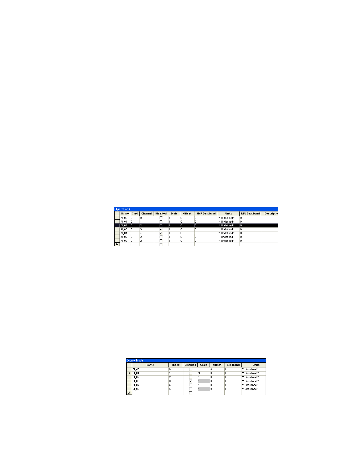
To select a column or a row:
Click the header of the line you want to select.
To select several rows or columns, hold down the CTRL key while clicking their header.
To select a group of rows or columns in a sequential order, select the header of the first one,
hold down the SHIFT key and select the last one.
5.8.2 Duplicating a Line
Proceed as follows to duplicate a line:
Click the header of the line you want to duplicate.
In the Edit menu, click Duplicate Line.
The line is duplicated after the last line in the display.
In the following example, we clicked on a line and clicked the Duplicate Line command twice, so
the line appears twice at the bottom of the list.
5.8.3 Copying a Value to a Group of Cells
The Change Selection command of the Edit menu allows you to copy a value from a particular
cell, to one or more lines selected within the same column.
To copy a value to one or more selected cells:
Click the cell to which you want to copy a value.
If you are selecting more than one cell, use the CTRL key or the SHIFT key on your
keyboard, as per standard Windows procedure.
In the Edit menu, click Select Cells.
This makes the cells turn gray, as shown next.
SMP Gateway User Manual • 41
Page 56
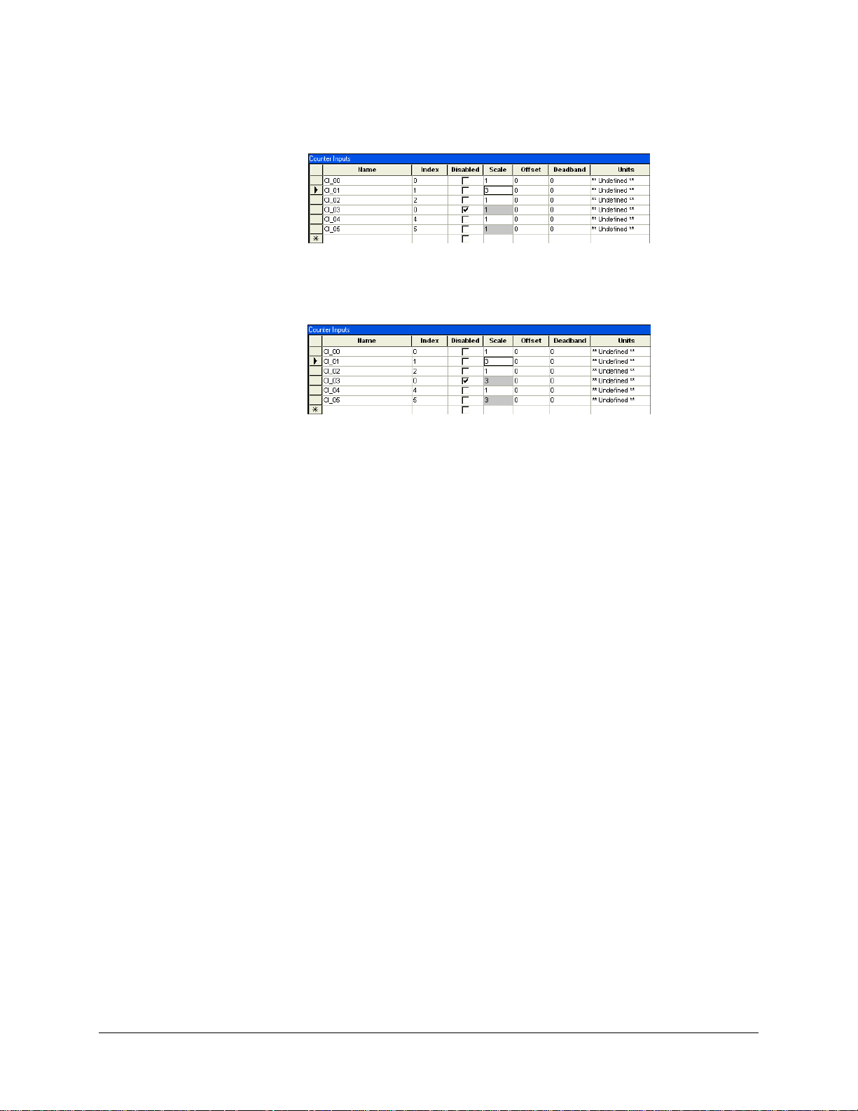
Click in the cell that contains the value you want to copy. In the example, we clicked in the
CI_01 Scale cell.
In the Edit menu, click Change Selection.
The value is copied to the selected cells.
To deselect the cells, click Clear Selection in the Edit menu.
Note:
If you have selected a group of cells and would like to add other cells to the group:
Select the desired cells using the CTRL key or the SHIFT key on your keyboard, per the
standard Windows procedure.
In the Edit menu, click Add to selection.
5.8.4 Resequencing a Group of Lines
Some settings are sequenced, within a given column. You may decide to remove data points, in
which case you will need to remove gaps in the numbering sequence. While resequencing all the
entries manually would be quite tedious, the Resequence Selection command of the Edit menu
makes it easy.
In the following example, the line with Index no. 7 has been deleted. All subsequent index
numbers are now incorrect.
42 • SMP Gateway User Manual
Page 57
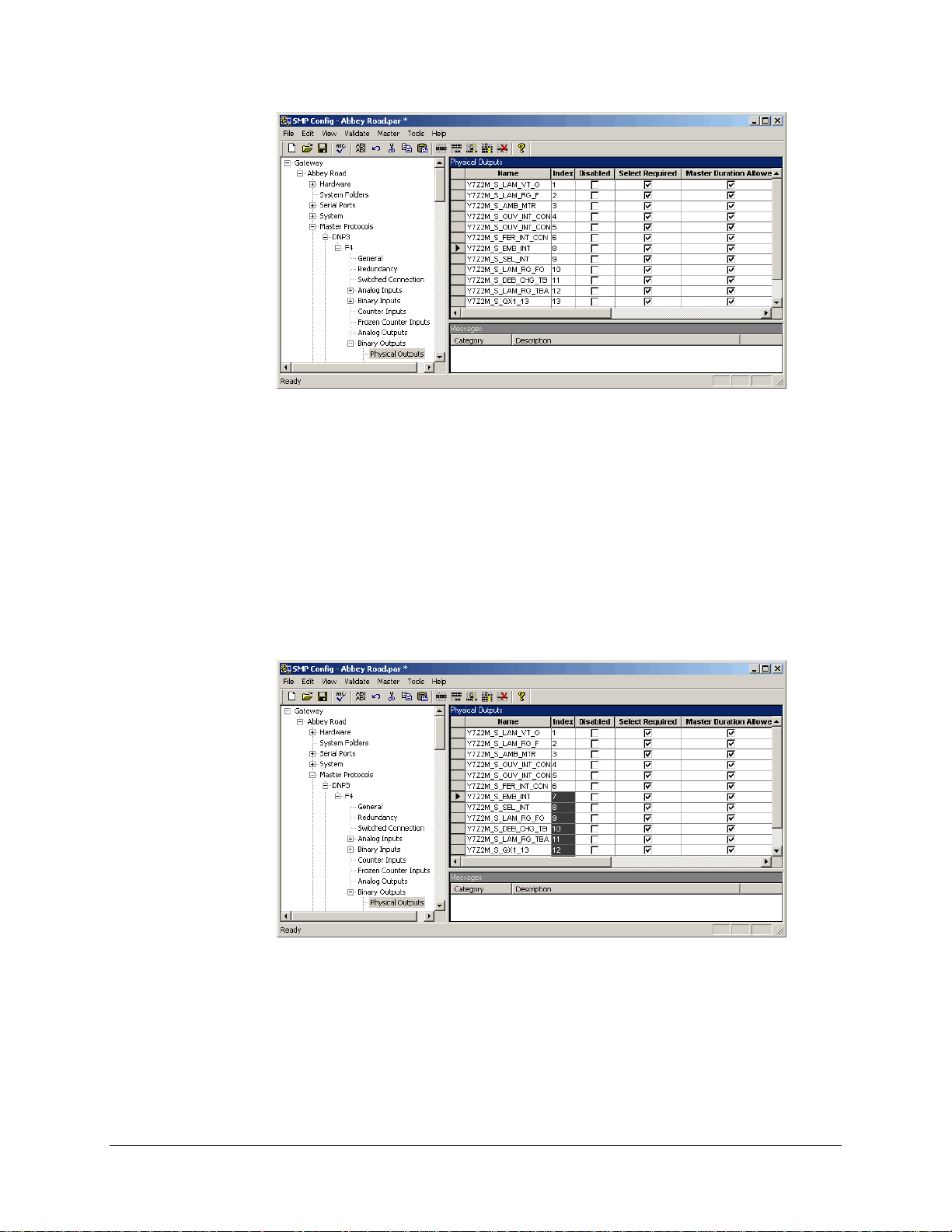
To correct the problem, proceed as follows:
Click the cell with Index no. 8.
Hold down the SHIFT key of your keyboard and click the last cell in the column.
In the Edit menu, click Select Cells.
The cells turn gray.
In the Edit menu, click Resequence Selection.
A dialog box appears, in which you must specify the starting sequence number (7) and the
increment (1). The result is shown next.
To deselect the cells, click Clear Selection in the Edit menu.
5.8.5 Deleting an Item
To delete a line in a grid:
In the right pane, click the header of the line you want to delete.
SMP Gateway User Manual • 43
Page 58
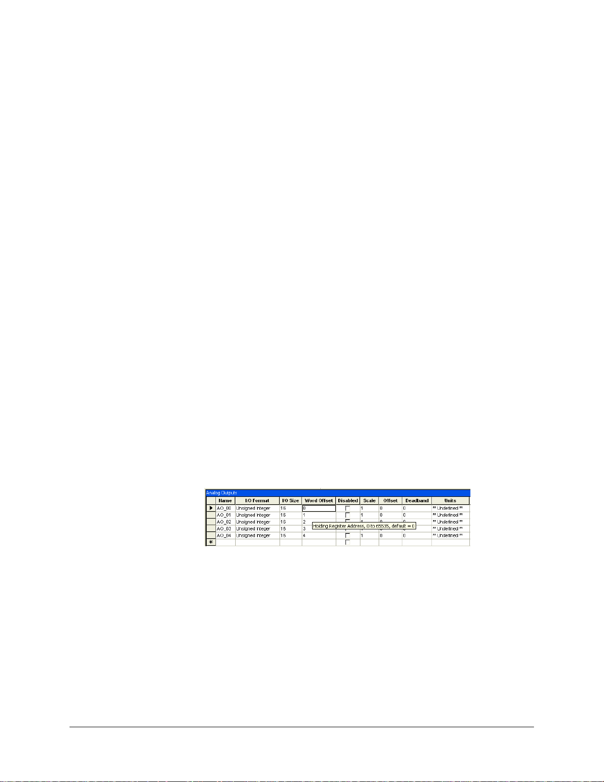
Press the Del key on your keyboard, and confirm your intention of deleting the row.
The item disappears from the grid.
To delete a protocol instance:
In the left pane, click the protocol type.
The list of instances of this protocol type appears in the right pane.
In the right pane, click the protocol instance you want to delete.
Press the Del key on your keyboard, and confirm your intention of deleting the row.
The protocol instance disappears from both panes.
To delete a serial port connection:
By their very nature, serial port connections cannot be deleted in the same way. To delete a serial
port connection, you have to reserve the corresponding serial port for another usage:
In the left pane, click Serial Ports.
In the right pane, choose Reserved in the Interface list of the serial port.
5.8.6 Using Tooltips
SMP Config provides context tooltips. These tooltips are not displayed on the status bar but rather
appear when you point with the mouse to a cell in any grid. This type of tooltip normally displays
the editing criteria for the field. For example, it may tell you that the value must fall between 10
and 1000, that the default value is 500 ms, that the field is mandatory if a certain other field is
selected, and so on. So they will assist you in editing grids.
Here is a sample tooltip:
This feature is a great time and effort saver, as it spares you from having to wait until you try to
validate or save your SMP configuration before finding out that you have a number of err ors.
5.8.7 Searching and Replacing Points in a Configuration
5.8.7.1 Finding Points in a Configuration
To help you find all the references to a point in a configuration, a search function is available in
SMP Config.
To access it:
44 • SMP Gateway User Manual
Page 59
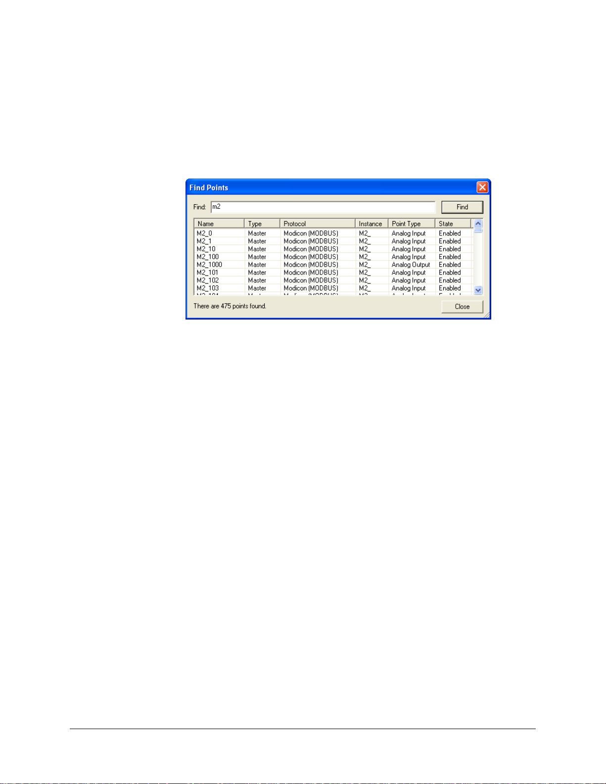
From the menu Edit, select Find Points or use the shortcut CTRL+F. The Find Points dialog
box appears.
In the Find Points dialog box, type the point’s name you are looking for and click the Find
button. The results appear in the list below.
Select the point in the list, the application will bring you to the configuration zone of the
point.
5.8.7.2 Replacing Points in a Configuration
As illustrated in the precedent section, one point can be used in several situations. If you need to
change the naming scheme in your configuration, simply rename the point and the other points
created from it will automatically bear the new name.
SMP Gateway User Manual • 45
Page 60

Page 61
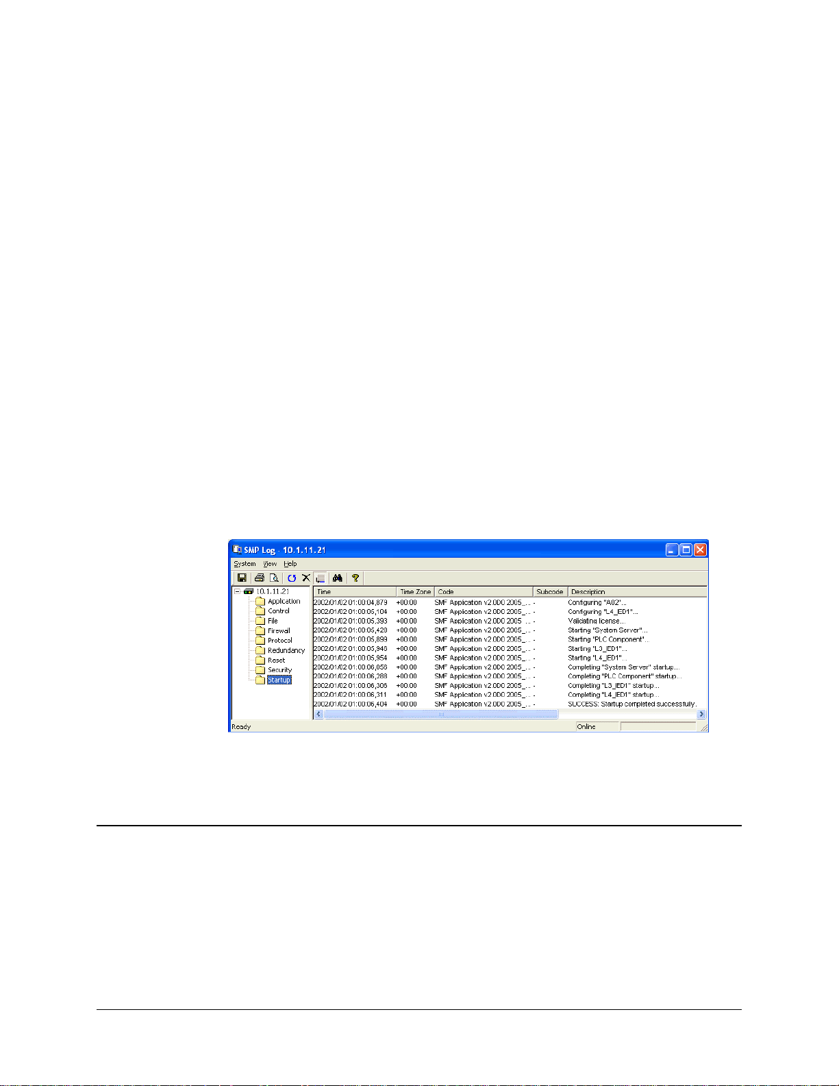
6 Viewing the SMP Log Files
The SMP Gateway maintains an internal log of all significant events. Using SMP Log, you can
select and view the various log files in real time. You can view, print, search and save all or any
information in this application.
To start SMP Log and view the SMP log files, proceed as follows:
Click your SMP Gateway in SMP Manager’s application window.
In the Tools menu, click SMP Log.
SMP Log starts up and displays the list of available logs.
Click a log in the left pane, to view its contents in the right pane.
6.1 Information Provided by SMP Log
The following log files contain information that you will find useful for the configuration and
maintenance of your SMP Gateway:
The Startup log records all the steps that the SMP Gateway performed when it last started.
The log indicates which configuration file was loaded and which protocol components were
configured and started. You should consult the startup log each time you change the SMP
configuration, in order make sure it is a success.
SMP Gateway User Manual • 47
Page 62

The Reset log records the time and reason for each SMP Gateway restart. It indicates whether
the reset occurred because of a power failure, a request from the front panel button, a remote
request, a watchdog trip, or a fatal hardware or software problem.
The Control log records the steps that the SMP Gateway performed in respon se to a local or
remote control request.
The Security log records all events that concern the security op tions such as authentication
failures, file integrity check and much more.
The other SMP log files contain information that can help you and our technical support team in
identifying problems.
6.2 SMP Log Features
SMP Log offers you several handy features: searching, printing and saving log f ile, and having the
information displayed in UTC or local time.
6.2.1 Searching in SMP Log
To search in SMP Log:
From the menu View, click Search.
Type a keyword in the text box and click the Search button. All the results will become
highlighted; the first one will be lighter.
To go to the next result, click Search Next in the View menu or press F3.
To go to the previous result, click Search Previous in the View menu or press F3.
Once you have found, click Cancel Search from the View menu and only the selected result
will remain highlighted.
6.2.2 Printing a Log
To print a log:
Select a folder.
From the menu View, click Print.
6.2.3 Saving a Log File
To save a log file:
Select a folder.
From the menu View, select Save As.
48 • SMP Gateway User Manual
Page 63

Type a name for the file; you can use a different extension such as .csv or .txt.
6.2.4 Viewing Multiple Log Folders at Once
To view multiple log folders at once:
Select folders, using the SHIFT or the CTRL key.
The contents of all folders will be displayed altogether in the right pane, in chronological
order.
6.2.5 Changing How Time Information is Displayed
To change how time information is displayed:
From the View menu, click Time Display Options.
From the Time Display Options dialog box, select the type of display from the Time Display
Format drop box: you can choose between the local time (using the PC’s time zone settings)
and UTC. Normally, your SMP Gateway’s clock is set in UTC, but you can display the
information using the time format you like.
SMP Gateway User Manual • 49
Page 64

Page 65

7 Viewing Protocol
Exchanges in Real Time
Using SMP Trace, you can view a continuous stream of protocol exchanges between the SMP
and the substation devices, or between the SMP Gateway and the control center.
At this stage, however, since you have only configured master protocol instances, you will only
see the protocol exchanges that take place between the SMP Gateway and the substation devices.
You can have the information displayed in UTC or local time, highlight the lines that contain
specific keywords, and you can clear the current display. SMP Trace can generate a continuous
log of all
a snapshot of the traced events that occurred since the last time you cleared the display.
To start SMP Trace and view the protocol exchanges:
the events you are tracing, to a text file on your PC. It can also print or save to a text file,
Click your SMP Gateway in the SMP Manager application window.
In the Tools menu, click SMP Trace.
7.1 Information Provided by SMP Trace
SMP Trace starts up and displays the list of available traces.
In the left pane, select the item for which you want to view the protocol exchanges.
If you click a folder, everything within the folder is automatically selected.
SMP Gateway User Manual • 51
Page 66
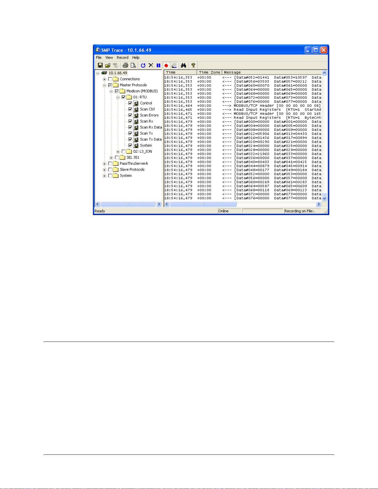
Using SMP Trace, you can view detailed traces of all the system activity. The following traces
provide information that you will find useful during the configuration and maintenance of your
SMP Gateway.
Master and Slave Protocol traces display the high-level information exchanges that occur
between the SMP Gateway and the other system components to which it is connected. These
application-level traces are similar to those provided by a protocol analyzer. They describe the
requests sent to a device and the values retrieved. The Slave Protocols folder appears only if
slave protocol instances are configured on the SMP Gateway.
Connection traces display the data being exchanged between the SMP and a device. These
low-level traces describe, in hexadecimal format, the byte stream sent and received to and
from a device.
7.2 SMP Trace Features
SMP Trace offers you several handy features: recording traces, searching, printing and saving
trace records, and having the information displayed in UTC or local time.
7.2.1 Searching in SMP Trace
From the menu View, click Search. You can also press CTRL+F.
Type a keyword in the text box and click the Search button. All the results will become
highlighted, and the first one will be lighter. You can click the Pause/Resume button in the
toolbar to stop the screen from scrolling; this command is also available from the View menu.
52 • SMP Gateway User Manual
Page 67
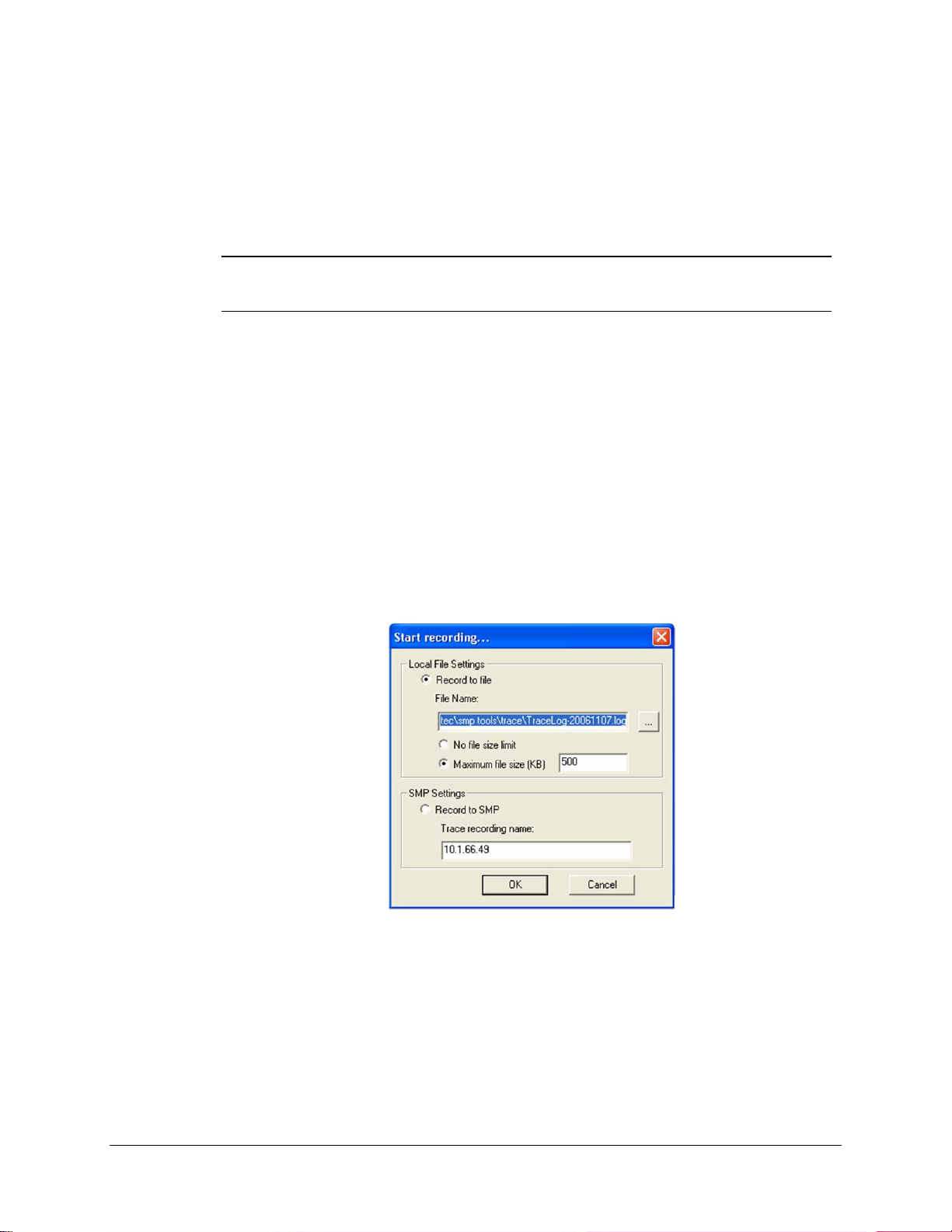
To go to the next result, click Search Next in the View menu or press F3.
To go to the previous result, click Search Previous in the View menu or press F3.
Once you have found, click Cancel Search from the View menu and only the selected result
will remain highlighted.
Note: SMP Trace will keep highlighting matching results as long as you have not
canceled the search. You can either deselect the binoculars in the toolbar or stop
the search from the View menu.
7.2.2 Printing Traces
To print currently displayed traces:
From the menu File, click Print.
7.2.3 Recording Live Traces
To record live traces to a file for further analysis:
From the Record menu, select Start or click the red button in the toolbar. The Start
recording dialog box appears.
You can also choose to save it inside the SMP Gateway's memory by selecting Record to
SMP. For example, if you have an SMP 4 with a modem on a pole outdoors and you need to
save 24 hours worth of activities, long distance costs are most of the time prohibitive. Use this
option and connect again 24 hours later to pick up your data.
When you wish to stop the recording, click the red button again or click Stop in the Record
menu.
SMP Gateway User Manual • 53
Page 68

7.2.4 Saving all the Scrolled Information
To save all the information in SMP Trace that scrolled since opening it:
Select a folder.
From the menu File, select Save As.
Type a name for the file; it will be saved in the .txt format.
7.2.5 Changing How Time Information is Displayed
To change how time information is displayed:
From the View menu, click Time Display Options.
From the Time Display Options dialog box, select the type of display from the Time Display
Format drop box: you can choose between the local time (using the PC’s time zone settings)
and UTC. Normally, your SMP Gateway’s clock is set in UTC, but you can display the
information using the time format you like.
54 • SMP Gateway User Manual
Page 69
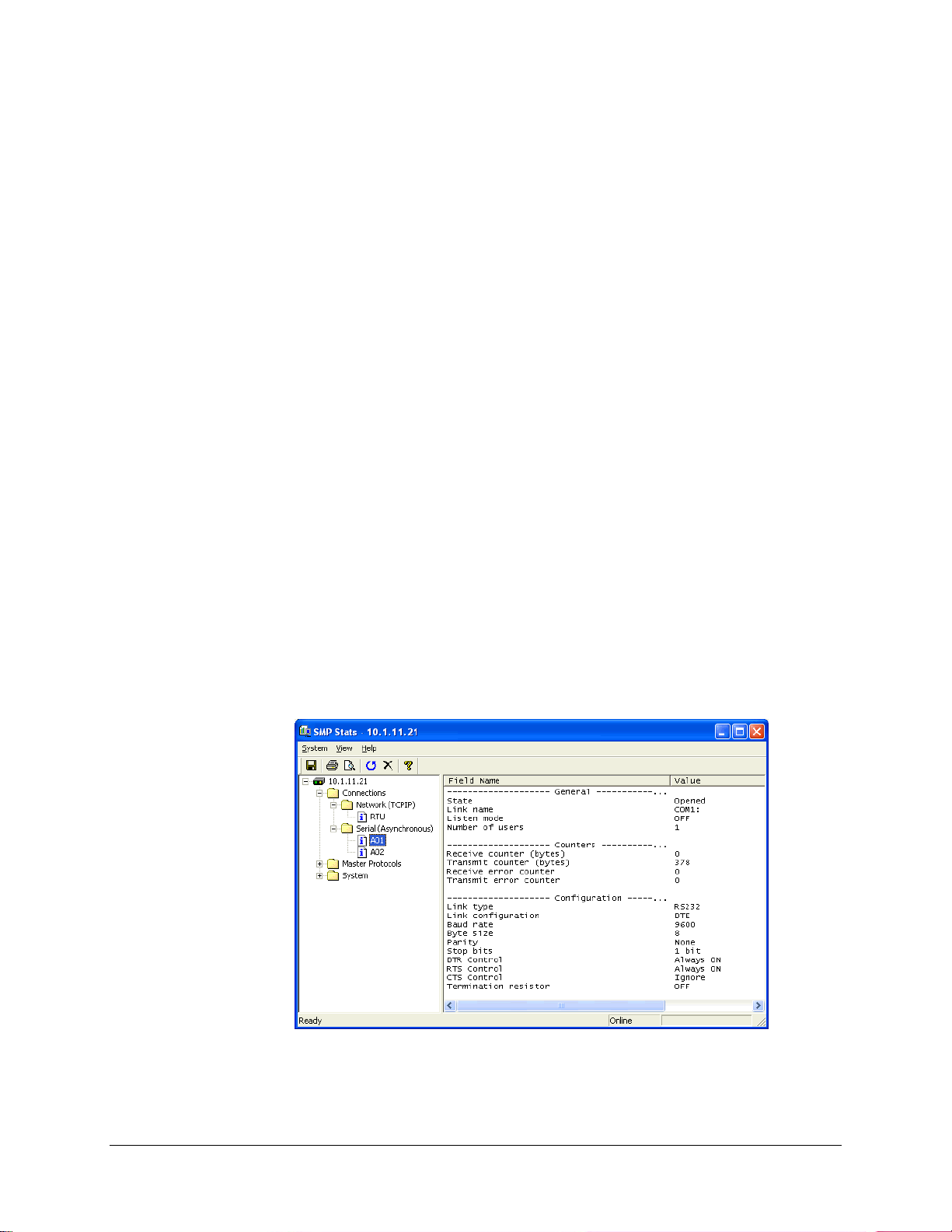
8 Viewing Communications
Statistics in Real Time
The SMP Gateway stores a large number of real-time statistics and internal counters to help you
analyze the performance of your SMP Gateway and assist you in troubleshooting your
configuration. Using SMP Stats, you can view, in real time, various statistics about the
communications links and about the protocol exchanges that take place between the SMP Gateway
and the devices or control centers. You can have the information displayed in UTC or local time.
You can also print the statistics, reset them, or save them to a text file for subsequent analysis.
To start SMP Stats and view the statistics:
Select your SMP Gateway in the SMP Manager application window.
In the Tools menu, click SMP Stats.
SMP Stats starts up and displays the list of available statistics.
In the left pane, click the item for which you want to view the statistics.
The statistics are displayed in the right pane and you can see them change dynamically.
SMP Gateway User Manual • 55
Page 70

8.1 Information Provided by SMP Stats
Statistics provide information on the SMP Gateway activity, which can be useful for the
configuration and maintenance of the gateway itself. This information is organized as pages and
folders. A folder does not contain any statistics: it is a place holder for statistics pages.
When you open SMP Stats, its displays the following folders:
The Connections folder regroups counters and statistics pages about the performance of the
SMP Gateway’s communications components:
The Network (TCPIP) folder contains the list of all the network connections you defined
under Connections, with SMP Config. Each connection has its own statistics page.
The Serial (Asynchronous) folder contains the list of all the serial connections. As in the
Network folder, there is a statistics page for each connection.
The Modem Pool folder contains the list of any modem pools and modems you may
have defined with SMP Config. The statistics found in these folders provide an easy way
to monitor the communications status of the SMP Gateway. For example, you can look at
the Receive counter and Transmit counter values to determine whether the gateway is
exchanging data with a connected device or control center.
Note: The Modem Pool folder is visible only for the SMP 16, which has an
integrated modem, and for an SMP 4 purchased with the modem support
option. Furthermore, a modem pool must be configured on the
SMP Gateway.
The Master Protocols and Slave Protocols folders contain counters and statistics about each
instance of a protocol component. Each protocol component contains protocol-specific items
that describe the messages exchanged with a device or control center. (The Slave Protocols
folder is missing, in the previous example, because we have to define slave protocol
components first.)
The System folder contains counters and statistics about the operation of the SMP Gateway
hardware and software.
8.2 SMP Stats Features
SMP Stats offers you several handy features: resetting statistics, printing them, refreshing them,
and changing how time is displayed.
8.2.1 Resetting Statistics
You can reset certain statistics, such as global RTDX or web server statistics:
From the menu View, select Reset; or click the 'X' button; or press CTRL+X.
56 • SMP Gateway User Manual
Page 71

8.2.2 Printing Statistics
To print a statistics page:
Select a folder.
From the menu File, click Print.
8.2.3 Changing How Time Information is Displayed
To change the display format of time-specific statistics:
From the View menu, click Time Display Options.
From the Time Display Options dialog box, select the type of display from the Time Display
Format drop box: you can choose between the local time (using the PC’s time zone settings)
and UTC. Normally, your SMP Gateway’s clock is set in UTC, but you can display the
information using the time format you like.
SMP Gateway User Manual • 57
Page 72

Page 73

9 Using a Web Browser to
View Data in Real Time
The SMP Gateway’s built-in web server (eSMP) provides an easy way to view the log files and
statistics using your Internet Explorer web browser. It is also the easiest way to view the analog
and binary input and output points in real time.
Note: The eSMP web server requires version 5.0 or a later version of the Microsoft
Internet Explorer web browser. JRE (Java Runtime Environment) must also be
installed on your computer. See your SMP Gateway’s installation guide for
details.
9.1 Connecting to the SMP Gateway’s Website
Whether it is to view the SMP Gateway’s log files, statistics or data points’ real-time data, you
always proceed the same way to connect to the SMP Gateway’s website:
In SMP Manager’s application window, select your SMP Gateway.
From the Tools menu, click Internet Explorer.
Your Internet Explorer web browser will open and connect to the SMP Gateway’s web server.
You may have to wait a few seconds while the web site is loaded and the Java platform is
initializing. The website’s home page will eventually appears in your browser.
9.2 Navigating Through the SMP Gateway’s Website
The SMP Gateway’s website has a number of tabs at the top that allow you to switch between
different data views:
The Home tab gives you key information about your SMP Gateway, such as its current state,
at what time it started up, and the list of master and slave protocol instances contained in your
configuration.
SMP Gateway User Manual • 59
Page 74
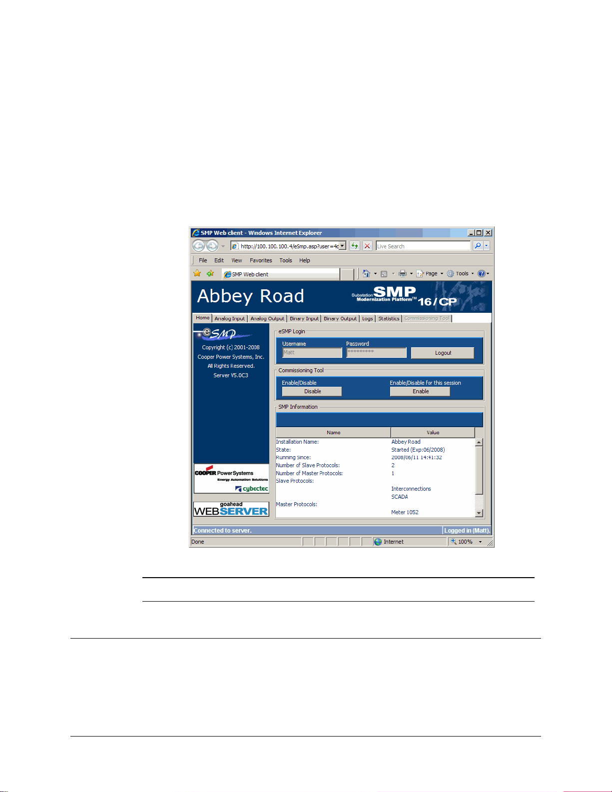
The Analog Input, Analog Output, Binary Input, and Binary Output tabs display the
current value of all the SMP Gateway’s data points.
The Logs tab displays the contents of the internal SMP Gateway log files. The data is the
same as provided by the SMP Log program.
The Statistics tab displays the SMP Gateway’s real-time statistics. The data is the same as
provided by the SMP Stats program.
The Commissioning Tool tab is only available when commissioning has been activated on
the SMP Gateway. For more information about this feature, see “Using the Web Server’s
ommissioning Tool”, page 69.
C
Note: If password security is enabled on your SMP Gateway, everything will be
deactivated until you type a valid username and password under eSMP Login.
9.3 Applying a Filter to a Data Point Display
If you click the Analog Input, Analog Output, Binary Input and Binary Output tabs, you can
see all the data points change dynamically on your screen. Since there may be a large number of
data points, you can use the Filter function to choose the points you want to display.
60 • SMP Gateway User Manual
Page 75
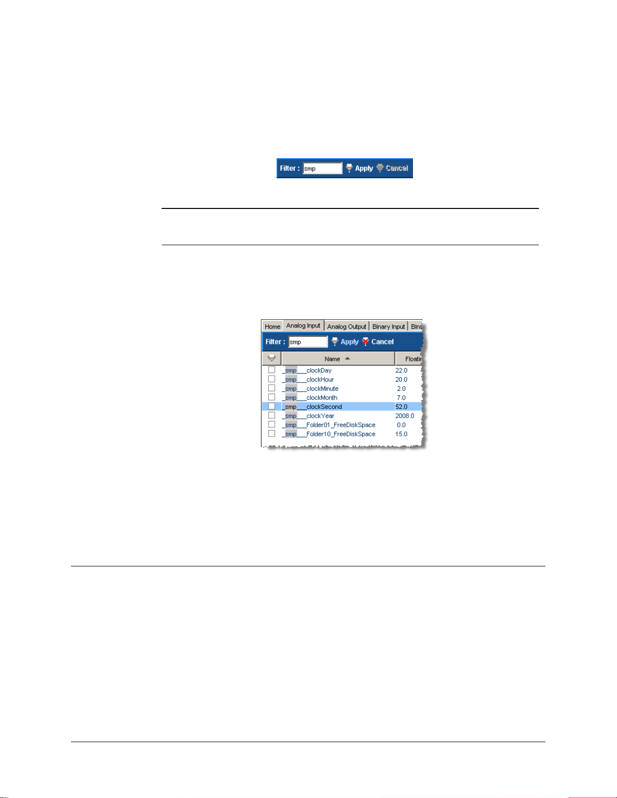
To apply a filter:
Select the tab in which you want to filter data points.
In the toolbar, type the filter criterion. It can be the device prefix, or any other text that is
common to the data points you want to display.
Note: You may specify up to 5 criteria. For example, if you type smp clock, all
data points that contain the words “smp” and “clock” will be displayed; others
will be hidden.
Click Apply. Only the data points that contain the filter criterion in any field (such as the
point’s name or address) will be displayed. The criterion text is highlighted over the point’s
name.
To remove the filter:
Click Cancel. All data points of the selected tab will be displayed.
Each tab preserved its own filter information, allowing you to navigate thro ugh the different
tabs and specify different filter criteria for each one of them.
9.4 Acknowledging Data Point Value Changes
To help you analyze your data, the web server automatically highlights any data point that changes
value, by displaying it on a gray background. The data point stays highlighted until you
acknowledge the change of value. You can also have the web server automatically acknowledge
value changes after a short delay.
To have Internet Explorer automatically acknowledge the value changes:
Click the appropriate tab to choose the type of data.
Select the Auto Ack. checkbox located at the top right, above the data point display.
SMP Gateway User Manual • 61
Page 76

Data points will now be highlighted when their value changes and the display will return to
normal after a short delay.
To manually acknowledge value changes for a particular type of data point:
Click the appropriate tab to choose the type of data.
Make sure that the Auto Ack. checkbox is cleared.
Data points will now be highlighted when their value changes. They will remain highlighted until
you acknowledge the change of value.
To remove all highlighting:
Click Acknowledge, located at the top left above the data point display.
62 • SMP Gateway User Manual
Page 77

10 Connecting the
SMP Gateway to a Control
Center
Now that we have seen how to configure master protocol instances, tested the SMP Gateway
configuration and viewed the collected data, we will see how to configure a slave protocol
instance in order to forward the device data to a SCADA or a control center.
10.1 Creating Slave Protocol Instances
When the SMP Gateway communicates with a control center, it acts as a slave and as such, needs
to use a slave protocol. One slave protocol instance is required per control center.
To create a slave protocol instance:
In the left pane of SMP Config, under Slave Protocols, click the protocol for which you want
to add an instance.
In the right pane, type the name of the new instance at the end of the list of names, and press
the TAB key.
The new protocol instance is added to the left pane, under the protocol branch you had selected. If
you expand the protocol branch, SMP Config displays the protocol instance’s defaul t set t i ngs.
10.2 Configuring Slave Protocol Instances
The configuration of a slave protocol component is similar to that of a master protocol component.
You choose the protocol, enter the protocol settings, and specify the data points you want
forwarded to the SCADA.
The following procedure describes how to configure a slave pr otocol instance:
SMP Gateway User Manual • 63
Page 78

In the left pane, click General, to display the list of general setting s for the selected slave
protocol instance.
In the right pane, enter the protocol settings.
For instance, to configure a DNP3 slave component, you would provide settings such as:
The Link Address, which identifies the logical slave device. The address has to match
the address used by the control center to communicate with the SMP Gateway.
The Master Link Address, which identifies the control center.
Whether or not you want to support Unsolicited Reporting.
In the left pane, click Default Variations.
In the right pane, specify how you want the data points to be reported. Fo r example, you may
want to specify that when there is a change to an analog input point, you want the change
reported as a 32-bit value, with the time at which the event took place.
A complete description of the protocol-specific settings is available in individual documents, such
as DNP3 Slave Protocol for example.
To access the various protocol documents:
Click Start, on the Windows taskbar.
Point to Programs, then Cybectec, then SMP Tools, and then Documentation.
In the Documentation menu, click Protocols.
10.3 Subscribing to the Master Data Points
Slave protocol instances subscribe to data points in the real-time database. Whenever a master
protocol instance writes to the database, the slave instance retrieves the data and applies its own
settings to make it compatible with the requirements of the control center protocol.
When you configure a slave protocol component, you select from among all the data points
defined by the master protocol components, those data points to which you want to subscribe.
In the left pane, click the slave protocol instance.
In the Tools menu, click Subscribe To.
The Subscribe to Master I/O dialog box appears.
64 • SMP Gateway User Manual
Page 79
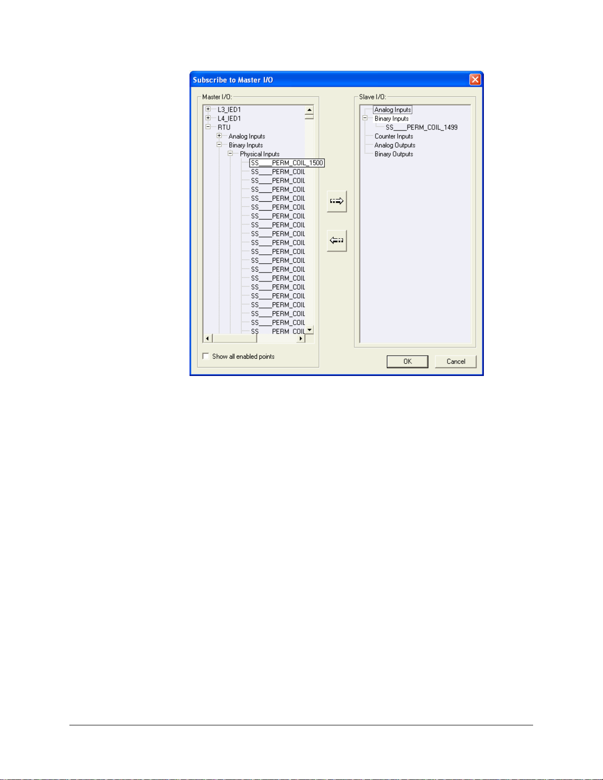
Click in the Master I/O list, to display the list of data points defined for each master protocol
instance.
Choose the data points you want to forward to the contro l center.
Use the CTRL and SHIFT keys on your keyboard, to extend your selection.
Click the dialog box’s right arrow button.
The data points you choose are added to the Slave I/O list. If, for example, you click a binary
input point in the Master I/O list, the point is added to Binary Inputs, in the Slave I/O list.
Normally, a data point that has been transferred to the Slave I/O list disappears from the Master
I/O list. However, if you want the transferred data points to continue being displayed in the
Master I/O list:
Select the Show all enabled points checkbox.
If you change your mind, you can remove a data point from the Slave I/O list as follows:
Click the data point in the Slave I/O list.
Click the dialog box’s left arrow button.
The data point is removed from the Slave I/O list and reinserted in the appropriate data point list
for the appropriate master.
SMP Gateway User Manual • 65
Page 80

10.4 Configuring the Data Points
The slave component automatically converts the subscribed data points to the appropriate format
for the protocol. However, you should make sure the default settings are appropriate and perform
any necessary adjustments.
To configure the data points:
In the left pane, click the data point type, to display a list of all the data points and their
settings.
There are different settings for each protocol. However, you should at least check the addr ess
or index assigned to each data point.
For instance, the following settings are provided for a DNP3 data point:
Each data point is automatically assigned an Index value according to the subscription
order. You should ensure that these index values correspond to those expected by the
control center.
The Event Class setting groups data points together for subsequent reporting to the
control center.
10.5 Configuring the Communications Links
We previously described how to configure a serial communications link for a master protocol
component. The procedure is identical for a slave protocol component that uses a serial
communications link. However, a slave protocol component typically uses a TCP/IP connection
over a LAN, to communicate with the control center. For more information about communications
link configuration, see “Configuring the Communications Links”, page 34.
10.5.1 Setting up a TCP/IP Slave Connection
To configure a TCP/IP connection for a slave protocol component:
In the left pane, under Connections, click TCP/IP Slaves, to display the list of defined
connections.
Enter the settings for the new TCP/IP connection in an empty row of the grid:
Specify a significant name for the connection.
Specify the TCP port number to be used.
10.6 Associating a Slave Protocol Instance with a Communications Link
You now have to identify the communications link which will be used by the slave component to
communicate with the control center.
66 • SMP Gateway User Manual
Page 81

To associate a slave protocol instance with a communications link:
In the left pane, click Connection usage.
In the right pane, for each slave protocol instance under Slave Connection Usage, select the
checkbox under the appropriate connection instance.
10.7 Validating and Activating the Configuration
You can now validate the configuration, save it on your computer, send it to the SMP Gateway,
and restart the gateway in order to activate the configuration.
The procedures for doing this were described earlier, in the following sections:
“Validating and Saving the Configuration”, page 38.
“Sending the Configuration to the SMP Gateway”, page 39.
10.8 Testing the Configuration
The SMP Gateway’s configuration now contains a slave component. Slave components are more
difficult to test than master components, since they only process data in response to a request from
a control center. You may find the following guidelines useful in determining whether the slave
component is working prope rl y :
Using SMP Log, check the Startup log, to see whether the slave component was started
correctly.
Using SMP Stats, open the Slave Protocols folder and check whether the slave component is
processing any data.
Using SMP Stats, open the Connections folder, and check whether any data is being
exchanged through the slave’s communications link.
Using SMP Trace, open the Slave Protocols folder, and check whether the component is
receiving requests from the control center.
Using SMP Trace, open the Connections folder, and check whether any data is being
exchanged through the slave’s communications link.
See the following sections for instructions on how to proceed to view the information:
“Viewing the SMP Log Files”, page 47.
“Viewing Protocol Exchanges in Real Time”, page 51.
“Viewing Communications Statistics in Real Time”, page 55.
“Using a Web Browser to View Data in Real Time”, page 59.
SMP Gateway User Manual • 67
Page 82

A particularly effective way to test a slave protocol instance is to use the SMP Gateway itself to
set up a master protocol instance to poll the slave. Using this approach and the SMP Tools, you
can easily examine the effect of the various protocol features, such as report by exception.
You can also use the web server’s commissioning tool, as described in the next chapter.
68 • SMP Gateway User Manual
Page 83

11 Using the Web Server’s
Commissioning Tool
The SMP Gateway’s built-in web server also provides a commissio ning tool that simplifies the
engineering effort required for the implementation and the integration of a substation. It is
intended to help technician(s) and/or engineer(s) testing the SMP Gateway’s configuration and
connectivity with the substation devices and the SCADA.
The web server’s commissioning tool, when configured and activated, is accessible through a web
browser, the same way than for viewing data in real-time. It may be enabled by users that have the
System Management privilege, and the operation privilege is required for users that will perform
the commissioning operations, which are essentially the following:
Forcing an analog/binary input point to a specific value/state.
This operation allows the validation of the configuration of the SMP Gateway’ slave protocol
and the SCADA, by verifying if all the gateway’s data points are correctly mapped on both
sides, if minimum/maximum values are correctly handled, etc.
Performing a control operation on an analog/binary output point.
This operation allows the validation of the master protocols’ configuration, by verifying if the
IEDs’ data points are correctly configured in their corresponding masters, if scale and offset
settings are correctly specified for each data point, etc.
For example, by forcing each data point of an IED on the SMP Gateway, the technician/engineer
can verify that these points are correctly configured, and that transitions/changes for these are
correctly handled by the SCADA. On the other side, by executing control operation directly on the
SMP Gateway, instead of performing them on the SCADA, the technician/engineer can validate
that the masters’ output points are correctly configured.
11.1 Configuring an SMP Gateway for Commissioning
If you intend to use the web server’s commissioning tool on your SMP Gateway, you must first
enable it in the gateway’s configuration, using SMP Config.
The configuration process is quick and simple, as described here:
In SMP Manager’s application window, select your SMP Gateway.
SMP Gateway User Manual • 69
Page 84
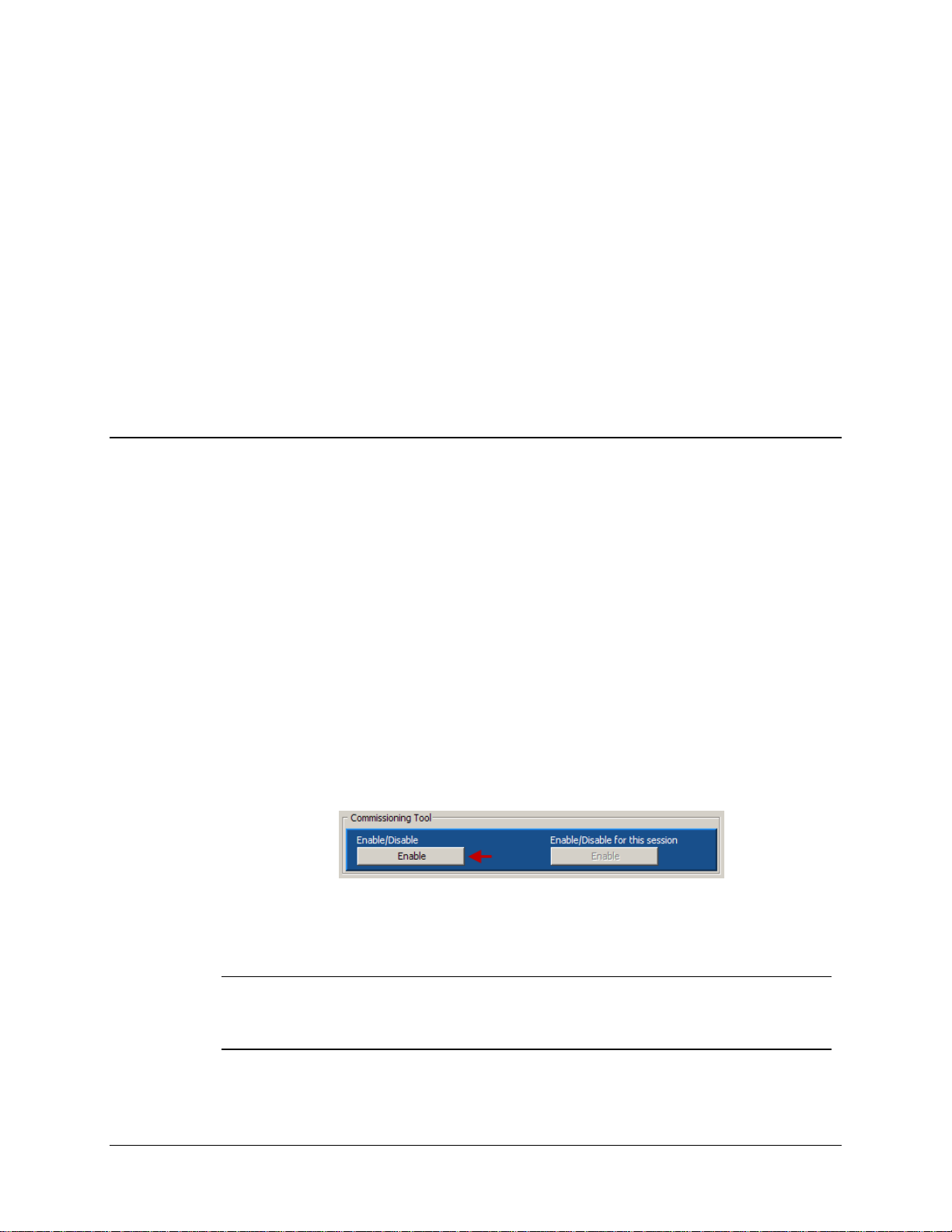
From SMP Manager’s Tools menu, click SMP Config.
In SMP Config, under the System branch, select Web Server. If the Web Server instance has
not been created yet, type a name in the blank Name text box, and then click again the Web
Server branch.
Under the Web Server instance branch, select the General branch.
Select the Commissioning Tool checkbox.
Save the configuration file and send it to the SMP Gateway, using SMP Manager.
Restart the SMP Gateway.
Your SMP Gateway now supports the commissioning feature, which still need to be activated by a
user that has the System Management privilege, as described in the following section.
11.2 Activating the Commissioning Feature
Commissioning is not a process that is performed frequently. Done once when the SMP Gateway
is deployed in the field, it may be executed later, during maintenance sessions or when new
devices are added to the substation’s configuration.
Before letting the user perform commissioning in the field, a user that has the System
Management privilege must activate the commissioning feature. Usually, this user would first
make sure that all safety precautions have been taken, that the SMP Gateway is really going
through maintenance and that the commissioning process may occur as planned. By activating the
feature, the operator in charge of commissioning can then open a commissioning session, and do
his work.
To activate the commissioning feature:
Connect to the SMP Gateway’s website, by following the procedure described in section 9.1,
page 59.
At the website’s home page, under Commissioning Tool, click the Enable button on the left.
The button’s text will change to Disable, and the button on the right will become available. The
operator may now open a commissioning session.
Note: Commissioning will remain active until the left button is clicked again to
deactivate it. If the SMP Gateway is restarted, the commissioning feature’s
activity state will be persisted: if it was active prior to the restart, it will be active at
startup and vice-versa. However, opened sessions are closed.
70 • SMP Gateway User Manual
Page 85
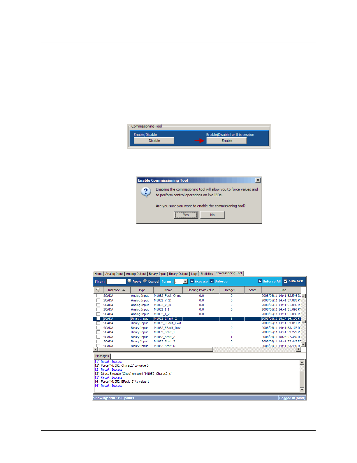
11.3 Opening a Commissioning Session
Once the commissioning tool has been activated on the SMP Gateway, any user that has the
Operation privilege can open a commissioning session. Proceed as follows:
Connect to the SMP Gateway’s website, by following the procedure described in section 9.1,
page 59.
At the website’s home page, under Commissioning Tool, click the Enable button on the
right.
The Enable Commissioning Tool dialog box will appears.
Click Yes.
The button’s text will change to Disable and the Commissioning Tool tab is now available. To
use the commissioning tool, simply click the Commissioning Tool tab.
SMP Gateway User Manual • 71
Page 86
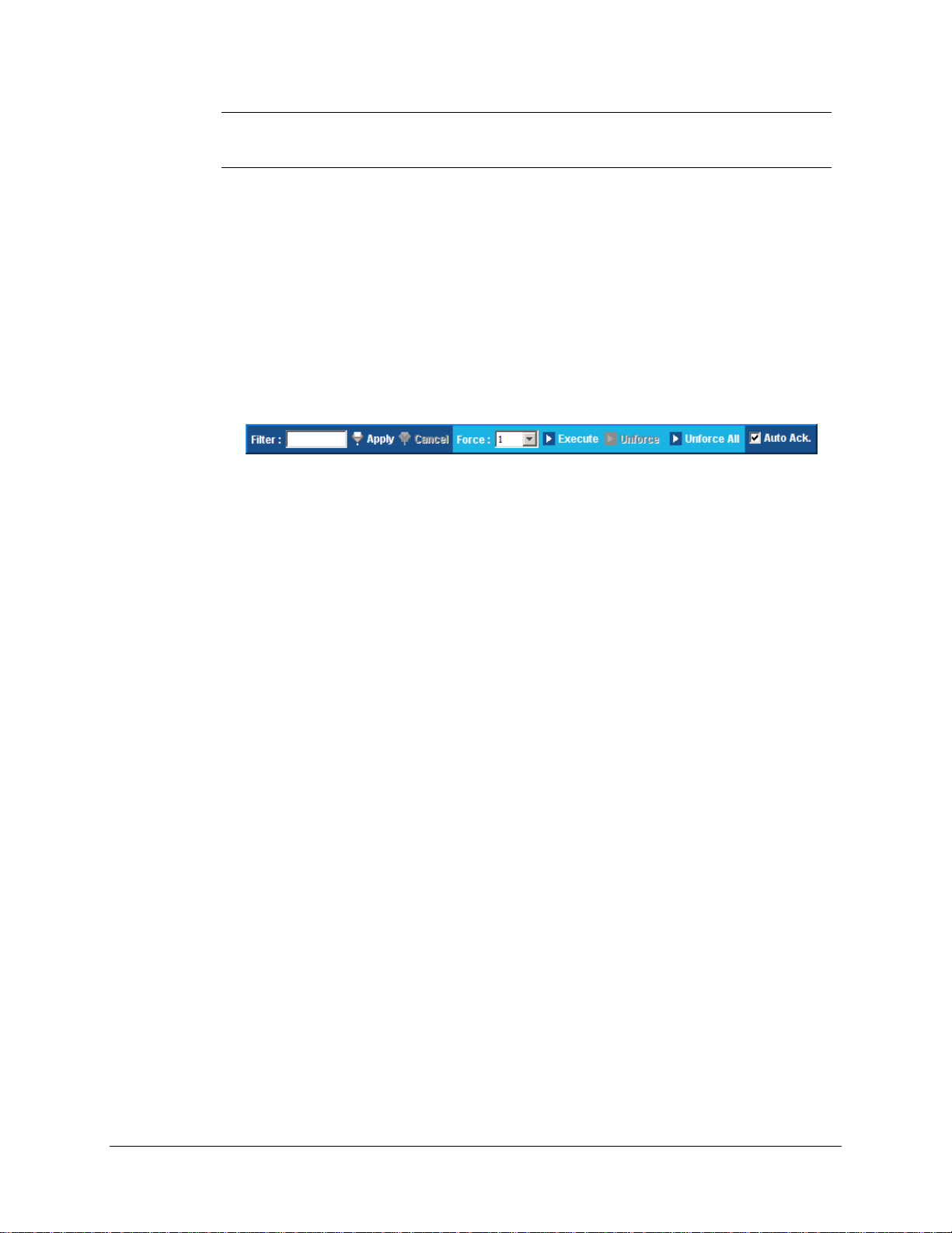
Note: The commissioning session will remain open as long as the web browser will
remain connected to the website, or until the user click again the button on the
right. The session is also closed when the SMP Gateway restarts.
11.3.1 The Commissioning Tab
The Commissioning tab looks quite similar to other data points tabs. It is divided in three
sections:
The toolbar, which is located at the top,
Is used for filtering, forcing, control operation and acknowledging purposes. It is an extended
version of the toolbar available in other data point tabs, and its content varies in function of
the type of the selected data point(s). The following figure shows the toolbar for a binary
input point:
The data points list.
Displays the data points of every protocol instance or subsystem of the SMP Gateway. This
implies that a data point that is configured in a master protocol and in two slave protocols will
be listed three times.
The Messages pane, which is located at the bottom.
Displays a log of all commissioning tool’s operations, statuses and errors.
The data points list’s column are mostly the same that are displayed in the other data points tabs.
The following columns are specific to (or different in) the commissioning tab:
Instance.
The name of the protocol instance or subsystem to which the data point belongs.
Type.
The data point’s type.
Integer Value.
Usually, the integer value of an analog point is displayed here. In the commissioning tool tab,
it is also used for the state of a binary input point, as the State column is only used for binary
output points.
State.
As stated above, in the commissioning tool tab, this column is used to display the current state
of a binary output point.
The various commissioning operations that you can perform are described in the following
sections.
72 • SMP Gateway User Manual
Page 87

11.3.2 Forcing an Input Point
The most common commissioning operation is to force an input point to a specific value/state, and
to verify that the forced value is correctly reported to the SCADA.
To force an input point to a specific value:
In the data points list, select the input point you want to test.
In the commissioning toolbar, specify the forced value/state:
If it is an analog input point, select whether to change the Integer or Float value of the
point, using the Force drop-down list, and then type the forced value in the edit box.
If it is a binary input point, select the desired state using the Force drop down list.
Still in the commissioning toolbar, click Execute to force the point to the specified value.
In the Messages pane, you should see two new messages: the first one indicates that the force
operation has been performed; the second displays the operation’s result.
If the operation was successful, the status column will display Forced (Test) for the data
point.
If the operation was successful and both the SMP Gateway and the SCADA are correctly
configured, the value/state changes should be reported correctly to the SCADA.
Note: You cannot force the value/state of multiple data points simultaneously.
11.3.3 Un-Forcing an Input Point
To un-force an input point:
In the data points list, select the forced input point.
In the commissioning toolbar, click Unforce.
The point will revert to its current value/state.
To un-force multiple input points simultaneously:
In the data points list, select more than one input points that have been forced.
In the commissioning toolbar, click Unforce All.
In the message box that appears, click Yes to un-force the selected input points.
Note: As stated in the message box, this operation may take a while, depending on the
number of input points to un-force. Also, data points included in the selection that
have not been forced will not be modified by this operation.
SMP Gateway User Manual • 73
Page 88

You can also un-force all forced data points, by clicking Unforce All in the commissioning
toolbar.
11.3.4 Performing a Control Operation
When an IED support control operations, it is important to validate that its related outpu t points
are correctly configured on both the SCADA and the SMP Gateway sides. Such validation is
achieved in two steps, for each output point:
Perform a control operation using the Commissioning Tool, to make sure that the point is
correctly configured in the SMP Gateway’s master configuration and that the control result is
correctly reported to the SCADA.
Perform a control operation from the SCADA standpoint, as a final validation to make sure
that both the SCADA and the SMP Gateway’s slave configurations are correct.
To perform a control operation using the commissioning tool:
In the data points list, select the output point you want to test.
In the commissioning toolbar:
Specify the control type using the Control drop-down list.
Note: If the output point supports select and execute control types, remember to
test both control types.
Specify the control value:
If it is an analog output point, select the control value type (Integer or Float) using
the appropriate drop-down list, and then type the control value in the edit box.
If it is a binary output point, select the control state (Pulse, Open or Close) using the
appropriate drop-down list. If you selected Pulse, type the pulse’s duration, in
milliseconds, in the edit box.
Click Execute to perform the control operation.
In the Messages pane, you should see two new messages: the first one indicates that the
control operation has been performed; the second displays the operation’s result.
If the operation was successful and both the SMP Gateway and the SCADA are correctly
configured, the control operation’s result should be reported correctly up to the SCADA.
Note: You cannot perform control operations on multiple output points simultaneously.
As mentioned earlier in this section, the validation of the output point`s configuration at the
SCADA and in the SMP Gateway is achieved by performing a control operation directly from the
SCADA. Even if it does not involve the commissioning tool, the web browser can still be useful,
since it gives access to the SMP Gateway’s log files, including the Control log file.
74 • SMP Gateway User Manual
Page 89
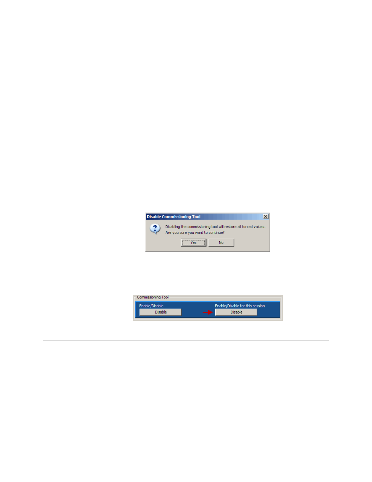
Various entries are added to the Control log when a control operation is executed on the
SMP Gateway, making it an essential resource for this portion of the commissioning task.
To consult the SMP Gateway’s Control log entries in the web browser:
Click the Logs tab.
In the left pane, select the Control log file. All the log entries will appear in the right pane,
the oldest entry being displayed at the top.
11.3.5 Closing the Commissioning Session
Even if a commissioning session automatically ends when the web browser is closed, you should
close the session manually.
Proceed as follows:
In the web browser, click the Home tab.
Under Commissioning Tool, click the Disable button on the right. The Disable
Commissioning Tool dialog box will appears.
As stated in the dialog box, the commissioning tool will restore all forced points to their
acquisition values. Click Yes. The button’s text will change to Enable and the
Commissioning Tool tab will no longer be available, until a new session is opened..
11.4 Deactivating the Commissioning Feature
When commissioning has been performed on the SMP Gateway, the user that has System
Management privilege must deactivate the commissioning feature for obvious safety reasons and
to ensure that the system will function as expected.
To deactivate commissioning:
Connect to the SMP Gateway’s website, if you are not already connected, by following the
procedure described in section 9.1, page 59.
At the website’s home page, under Commissioning Tool, click the Disable button on the left.
The button’s text will change to Enable, and the button on the right will become unavailable.
SMP Gateway User Manual • 75
Page 90

76 • SMP Gateway User Manual
Page 91

12 Interconnecting
SMP Gateways
It is possible to connect two SMP Gateways together, by the means of the Interconnections
feature. One advantage of such connectivity is the ability to concentrate d ata from multiple
SMP Gateways, which is very convenient considering the limited amount of IEDs that can be
monitored by a single SMP Gateway. You can also have a setup where the SCADA has only
access to one SMP Gateway (for security reasons, for example), while the substation actually
contains much more. It would be possible to interconnect two SMP Gateways using another
protocol, such as DNP3. However, it would require a considerable configuration effort, which is
not the case with Interconnections: data point information and configuration is exchanged between
both SMP Gateways.
The Interconnections feature and standard acquisition are based on the same master/slave
principles. For Interconnections, the SMP G at eway that pr ovides the data is the slave gateway, and
the one that retrieves the data from the other is the master gateway. So, to connect two gateways
together, a slave Interconnections instance must be configured in the slave gateway, and a master
Interconnections instance must be configured in the master gateway.
Consider a substation configuration wher e an IED’s data is retrieved by an SMP Gateway called
Cedar Creek (i.e. the slave gateway). An SMP Gateway called Park Avenue (i.e. the master
gateway) needs to get connected to it to make the IED data available to the SCADA. This example
is presented in the following illustration:
SMP Gateway User Manual • 77
Page 92
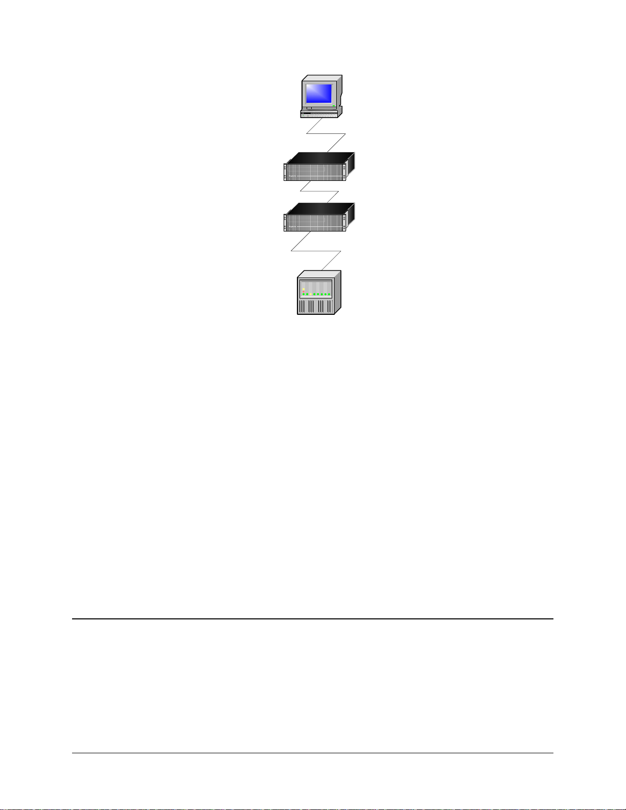
SCADA
PARK AVENUE
DNP3 MASTER
DNP3 SLAVE
INTERCONNECTIONS MASTER
INTERCONNECTIONS SLAVE
CEDAR CREEK
IEDs
MASTER
SLAVE
If you move from IEDs up to the SCADA, you will see how the master-slave configuration must
be designed for this to work.
The main steps are the following, using SMP Co nfi g:
In the device's master (here, the Cedar Creek SMP Gateway), create an Interconnections
slave.
Create the Interconnections slave’s connection and associate it with the slave.
In the SCADA’s slave (in this example, the Park Avenue SMP Gateway), create an
Interconnections master.
In the Interconnections master, import the data points from the slave SMP Gateway’s
configuration file.
Give the data points a prefix to identify their originating SMP Gateway when you see their
readings in the web browser.
Create the master’s connection and associate it with the master.
The following sections explain these steps in details.
12.1 Configuring the Slave SMP Gateway
The first step to interconnect your SMP Gateways is to signify the existence of the master
SMP Gateway in the slave SMP Gateway’s configuration.
Follow these steps:
Open SMP Manager.
78 • SMP Gateway User Manual
Page 93
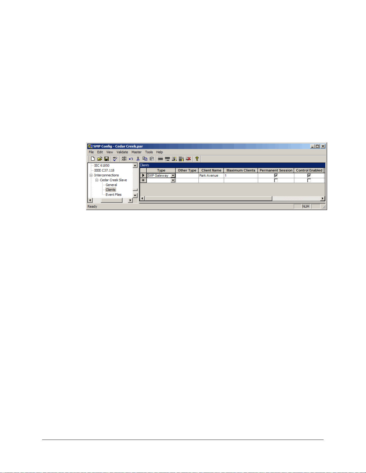
Select the slave SMP Gateway (in the example, the Cedar Creek SMP Gateway).
From the Tools menu, select SMP Config.
Configure the Interconnections slave instance:
In SMP Config, under Slave Protocols, select Interconnections.
In the right pane, under Name, type a name for the interconnections slave instance, and
then click again the Interconnections branch.
A new branch will appear under Interconnections, named after what was just typed.
Expand it and select the Clients branch.
Under Type, select SMP Gateway. Under Client name, type the client name (you can
use the gateway’s name, which in the example is Park Avenue). This name should be
unique for a given type of client.
Clear the Control Enabled checkbox if you do not want to allow control operations
through the interconnection. This is required if you do not want to allow SCADA control
operations of an IED through the interconnected SMP Gateways.
If you intend to exchange files between the interconnected gateways, you must define a
single client for each master gateway connected to the slave gateway. Each client must be
defined on a single line, as follows:
Type a Client Name.
Select the Permanent Session checkbox.
Make sure the Maximum Clients parameter is set to 1.
To learn how to specify the file exchange-specific settings, see “Retrieving files from
her SMP Gateway”, page 122.
anot
Configure the slave’s connection:
SMP Gateway User Manual • 79
Page 94
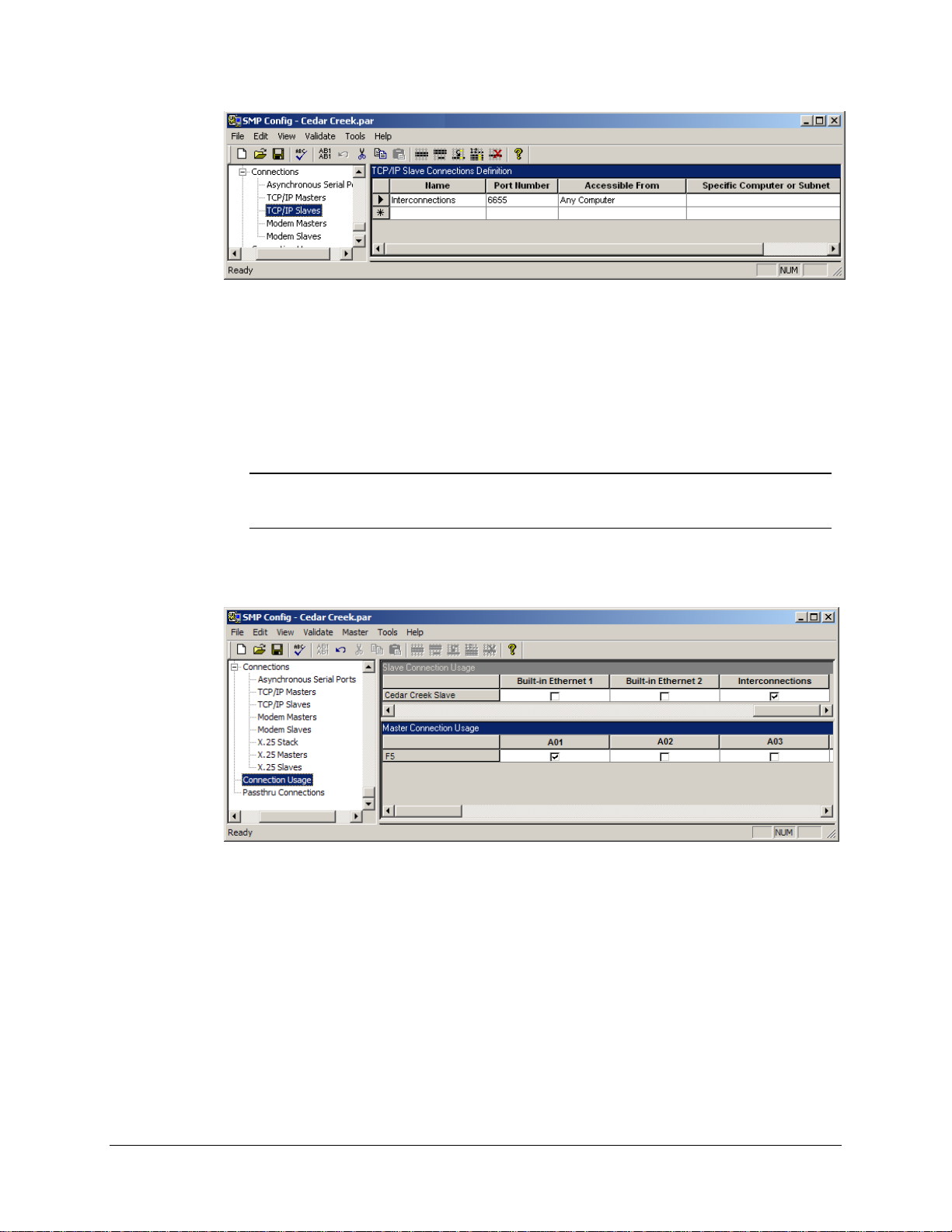
Collapse the Slave Protocol branch and expand Connections, and then select TCP/IP
Slaves.
Under Name, type the TCP/IP slave's name. For example, you can name it
Interconnections.
Under Port, type 6655.
Note: Port 6655 is recommended for Interconnections. You can use another port,
but make sure you specify the same in the master SMP Gateway’s
configuration.
Configure the connection usage:
Click the Connection Usage branch.
In the right pane, under Slave Connection Usage, you will see the Cedar Creek Slave
you created in the previous steps. Scroll to the right and select the checkbox under the
TCP/IP slave's name (in the example, the name is Interconnection).
Save the configuration file and close SMP Config.
Send the configuration file to the SMP Gateway using SMP Manager (see “Updating the
Configuration File” on page 225).
Restart the SMP Gateway.
80 • SMP Gateway User Manual
Page 95

Note: As all data points are always made available by an Interconnection slave
instance, the slave’s configuration does not need to be updated when a master’s
configuration is modified (for example, when a data point is added/removed) or
even when a new master is added to the SMP Gateway configuration.
12.2 Configuring the Master SMP Gateway
Now that you have configured the slave SMP Gateway as an Interconnections slave, you will
configure the master SMP Gateway as an Interconnections master. Follow these steps:
Open SMP Manager.
Select the master SMP Gateway (in the example, the Park Avenue SMP Gateway).
From the Tools menu, select SMP Config.
Configure the Interconnections master:
In SMP Config, under Master Protocols, select Interconnections.
In the right pane, under Name, type the slave SMP Gateway's name (in our example,
Cedar Creek), and then click again the Interconnections branch.
A new branch will appear under Interconnections, named after what was just typed.
Expand it and select the General branch.
In the right pane, under Device Prefix, type the prefix that will precede the name of all
data points gathered by the Interconnections master, to distinguish them from the data
points of other masters that may be configured on the same SMP Gateway. For example,
you can type PA_, where PA stands for Park Avenue, the example’s master
SMP Gateway.
Note: The device prefix should be as short as possible, to respect the maximum
length allowed for data points.
Under Client Name, type the same name you specified in the clients list of the
Interconnections slave (in this example, Park Avenue).
Import the slave SMP Gateway’s data points in the master’s configuration:
From the Tools menu, select Import Points from File.
Select the configuration file for the slave (ex. Cedar Creek SMP Gateway's file would be
Cedar Creek.par), and then click Open.
The Update Data Points dialog box will appear, listing all the possible data points that
can be "interconnected".
SMP Gateway User Manual • 81
Page 96
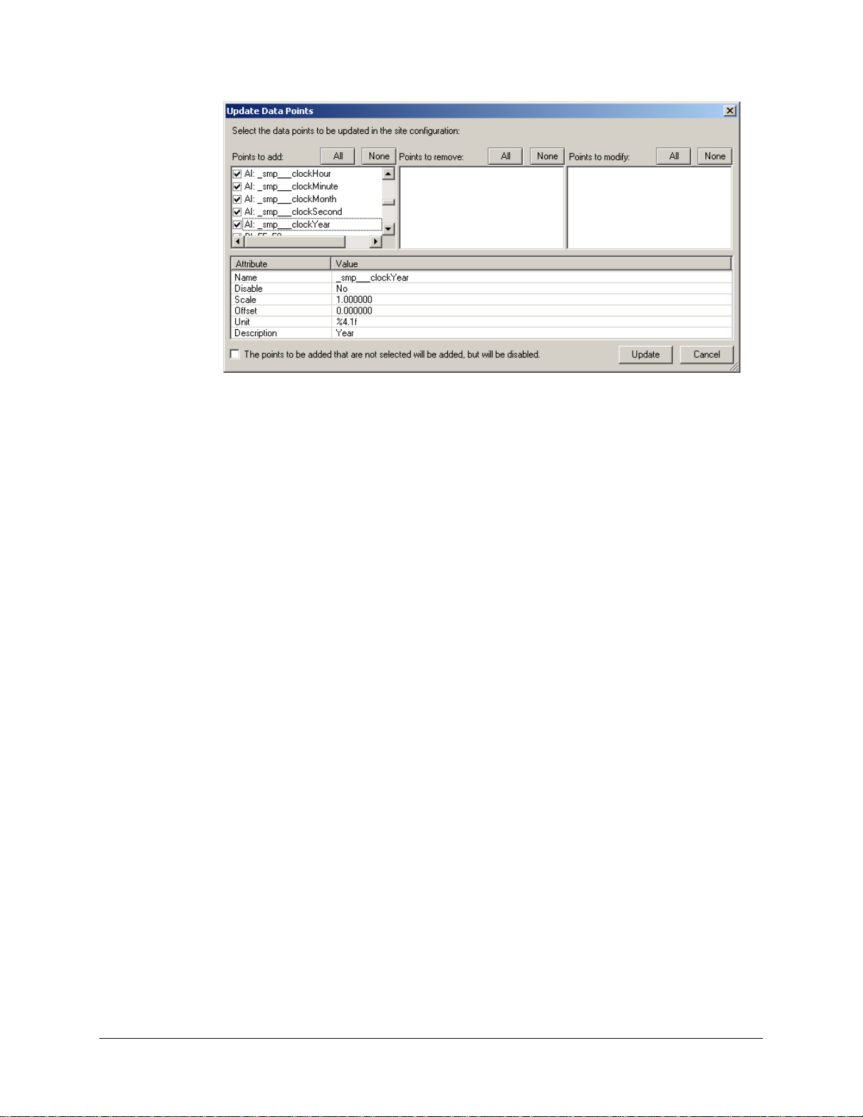
If some data points are not required in the master SMP Gateway’s configuration, clear the
corresponding checkboxes.
Click Update to close this dialog box and to add the points to the configuration.
Configure the master’s connection:
Collapse the Master Protocol branch and expand Connections, and then select TCP/IP
Masters.
Under Name, type the TCP/IP master's name. For example, you can name it
Interconnection.
Under IP Address, type the slave SMP Gateway's IP address.
Under Port, type 6655. If you specified a different port for the Interconnections slave,
type this port number.
Configure the connection usage:
Click the Connection Usage branch.
In the right pane, under Master Connection Usage, you will see the Cedar Creek
master you created in the previous steps. Scroll to the right and select the checkbox under
the TCP/IP master’s name (in the example, the name is Interconnection).
Save the configuration file and close SMP Config.
Send the configuration file to the SMP Gateway using SMP Manager (see “Updating the
Configuration File” on page 225).
Restart the SMP Gateway.
82 • SMP Gateway User Manual
Page 97

12.2.1 Updating the Interconnections Master’s Data Point List
When the slave SMP Gateway must monitor new IEDs or more information from actual IEDs, no
update is required for the slave SMP Gateway’s Interconnections instance. This is not the case for
the master SMP Gateway, but the configuration effort is minimal.
The Interconnections master’s data point list is updated nearly the same way than it is created the
first time.
Proceed as follows:
In SMP Config, under Master Protocols, select Interconnections, and then select the master
instance.
From the Tools menu, select Import Points from File.
Select the configuration file for the slave SMP Gateway, and then click Open.
The Update Data Points dialog box will appear, listing:
points that are available and that are not actually “interconnected”;
interconnected points are no longer available on the slave SMP Gateway;
interconnected points for which the settings (ex. Scale, offset, etc.) have changed.
Using the checkboxes that are found beside every data points, select the changes you want to
apply to the master’s configuration:
Under Points to add, clear the checkboxes of points that you still do not want to be
interconnected.
If you want to keep, in the master’s configuration, points that are no longer
interconnected, clear the corresponding checkboxes under Points to remove. This may
happen if a point is temporarily unavailable on the slave SMP Gateway.
If you want the settings of modified interconnected points to remain unchanged, clear the
corresponding checkboxes under Points to modify.
Click Update to close this dialog box and to add the points to the configuration.
Save the configuration file and close SMP Config.
Send the configuration file to the SMP Gateway using SMP Manager (see “Updating the
Configuration File” on page 225).
Restart the SMP Gateway.
SMP Gateway User Manual • 83
Page 98

12.3 Verifying the Interconnection Between the SMP Gateways
To verify if both SMP Gateways have been properly interconnected:
Launch SMP Manager.
Select the master SMP Gateway (in our previous example, it is the Park Avenue
SMP Gateway).
From the Tools menu, select Internet Explorer. The web browser will connect to the
gateway’s web server (see “Using a Web Browser to View Data in Real Time”, page 59 for
ore information about the SMP Gateway’s web features).
m
If the gateways are correctly interconnected, you will see the slave gateway’s data points in
the browser. Each data point will be preceded by the prefix you defined in the master
gateway’s configuration. If the IEDs are correctly connected to the slave SMP Gateway, the
displayed status of each interconnected data point should be OK.
84 • SMP Gateway User Manual
Page 99

13 Security
To derive full benefits from IED integration, substation data must be available to users at
enterprise level. However, widespread data access can become an important security risk if it is
compromised.
In August 2003, the North American Electric Reliability Council (NERC) issued the NERC
1200 Urgent Action Cyber Security Standard in order “To reduce risks to the reliability of the
bulk electric systems from any compromise of critical cyber assets (computers, software and
communications networks) that support those systems.”
The NERC 1200 standard evolved into NERC 1300, and is now known as NERC CIP-002-1 to
CIP-009-1 Cyber Security Standards. These standards describe measures that utilities will have
to implement, as well as a strict timeline for implementation.
This chapter describes the advanced security features that Cooper Power Systems has
implemented since version 4 of the SMP Gateway software and tools, in order to provide utilities
with a secure, NERC-compliant, solution to integrate their substation devices. It then takes you
through the steps required to customize the security settings to suit the needs of your organization,
and provides some general guidelines on setting up a secure sub s tation LAN.
13.1 Meeting NERC CIP Requirements
The Cybectec SMP Gateway helps you meet NERC requirements by providing secure access to
substation devices. Its sophisticated software includes the following security features:
Authentication and authorization — Each user is authenticated by the SMP Gateway via a
user name and a password. Strong passwords, individual user accounts, user groups, and
detailed group permissions protect critical system functions from unauthorized access. All
access attempts are logged, and accounts are locked out in the event of multiple failed
attempts.
Protection from substation LAN security breaches — The SMP Gateway is protected by a
built-in firewall and a built-in VPN server. All TCP/IP ports are blocked, except those
required for control center communications and SMP Gateway status monitoring. All
communications between the SMP Gateway and the SMP Tools goes through an encrypted
VPN tunnel, even through active passthrough connections.
SMP Gateway User Manual • 85
Page 100

Monitoring and locking of remote connections — Modem and passthrough access is
continuously monitored, and can be enabled or disabled by the control center. All accesses are
logged and limited to authorized users.
Integrity checking — All SMP Gateway software and firmware components are digitally
signed in order to ensure their authenticity and integrity. All executable files are also
continuously monitored to prevent execution of unau thorized code.
13.2 Substation Network Security Considerations
13.2.1 Setting Up a Secure Substation LAN
Security, as implemented on the SMP Gateway, is not a substitute for full network security that
includes properly configured firewalls. It can be argued that if unauthorized users get as far as
trying out the SMP Gateway’s security features, there has already been a security breach at some
other level. The goal of the SMP Gateway’s built-in firewall, simply stated, is to minimize the risk
of unauthorized access (or network traffic) to internal components on the PCN or SCADA
systems.
The substation LAN is a critical part of a utility’s network. To ensure its integrity, it must be
isolated as much as possible from the outside world. Ensuring the security of the substation LAN
is a complex subject beyond the scope of this document. However, we will provide in this section
some general guidelines on setting up a secure substation LAN.
A corporate LAN provides a number of access points to the outside world and is exposed to a
variety of threats through its connection to the Internet, external mail servers and file transfers,
which may contain viruses. If there is a direct connection between the corporate LAN and
substation LANs, the substation is not secure.
A significant improvement is the use of firewalls with the ability to establish a number of
demilitarized zones (DMZ) between the enterprise and process control networks. Each DMZ holds
a separate "critical" component, such as the data historian, the wireless access point or remote and
third party access systems. In effect, the use of a DMZ-capable firewall allows the creation of an
intermediate network often referred to as a process information network ( PIN ).
Creating a DMZ requires that the firewall offer three or more interfaces, rather than the typical
public and private interfaces. One of the interfaces is connected to the enterprise and the second, to
the PCN/SCADA network; the remaining interfaces are connected to the shared or insecure
devices, such as the data historian server or wireless access points.
To isolate the substation LAN, you should take the following pr ecautions:
There should be no email access.
There should be no Internet access.
There should be no direct connection to the corporate LAN.
Furthermore, a redundant path should be provided between the SCADA and the substation, to
ensure continued operation in the event of a failure of the corporate WAN. A dedicated
communications line is often maintained for this purpose.
86 • SMP Gateway User Manual
 Loading...