

Page 1

Super 80
Professional
Aircraft Operating Manual
By Coolsky, 2018
Version 2.0
Page 2

Super 80 Professional – AOM
TABLE OF CONTENTS
Super 80 Professional – Aircraft Operating Manual
SECTIONS
Description ....................................................................................... 1
Limitations ........................................................................................ 2
Normal Procedures ......................................................................... 3
Operating Techniques .................................................................... 4
Emergency Procedures .................................................................. 5
Air Conditioning and Pressurization ............................................... 6
Anti-Ice and Rain Protection .......................................................... 7
Auto-Flight ........................................................................................ 8
APU ................................................................................................... 9
Communications ........................................................................... 10
Electrical ........................................................................................ 11
Fire Protection ................................................................................ 12
Flight Controls ................................................................................ 13
Flight Instruments ........................................................................... 14
Flight Management ....................................................................... 15
Fuel ................................................................................................. 16
Hydraulics ...................................................................................... 17
Landing Gear ................................................................................. 18
Miscellaneous ................................................................................ 19
Navigation ..................................................................................... 20
Oxygen .......................................................................................... 21
Power Plant .................................................................................... 22
Performance .................................................................................. 23
Warning Systems ........................................................................... 24
Coolsky, 2018
Page 3

Super 80 Professional – AOM
TABLE OF CONTENTS
Super 80 Professional – Aircraft Operating Manual
TABLE OF CONTENTS
SECTIONS .................................................................................................................................... 1
TABLE OF CONTENTS ................................................................................................................. 1
SECTION 1: DESCRIPTION 0
TABLE OF CONTENTS ................................................................................................................. 1
DIMENSIONS ............................................................................................................................... 2
TURNING RADIUS ....................................................................................................................... 4
COMPARTMENTS ....................................................................................................................... 5
INTERIOR ARRANGEMENT ........................................................................................................ 6
COCKPIT ARRANGEMENT ........................................................................................................ 7
OVERHEAD PANEL (AFT) .......................................................................................................... 8
OVERHEAD PANEL (FORWARD) .............................................................................................. 9
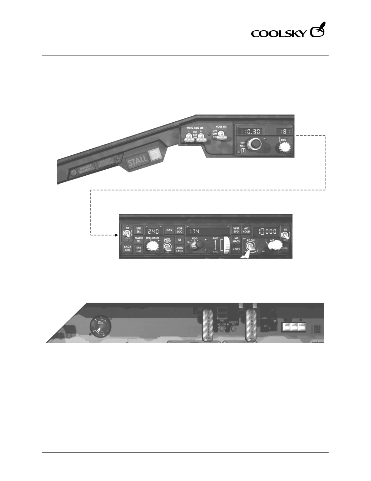
GLARESHIELD AND UPPER INSTRUMENT PANEL ................................................................... 10
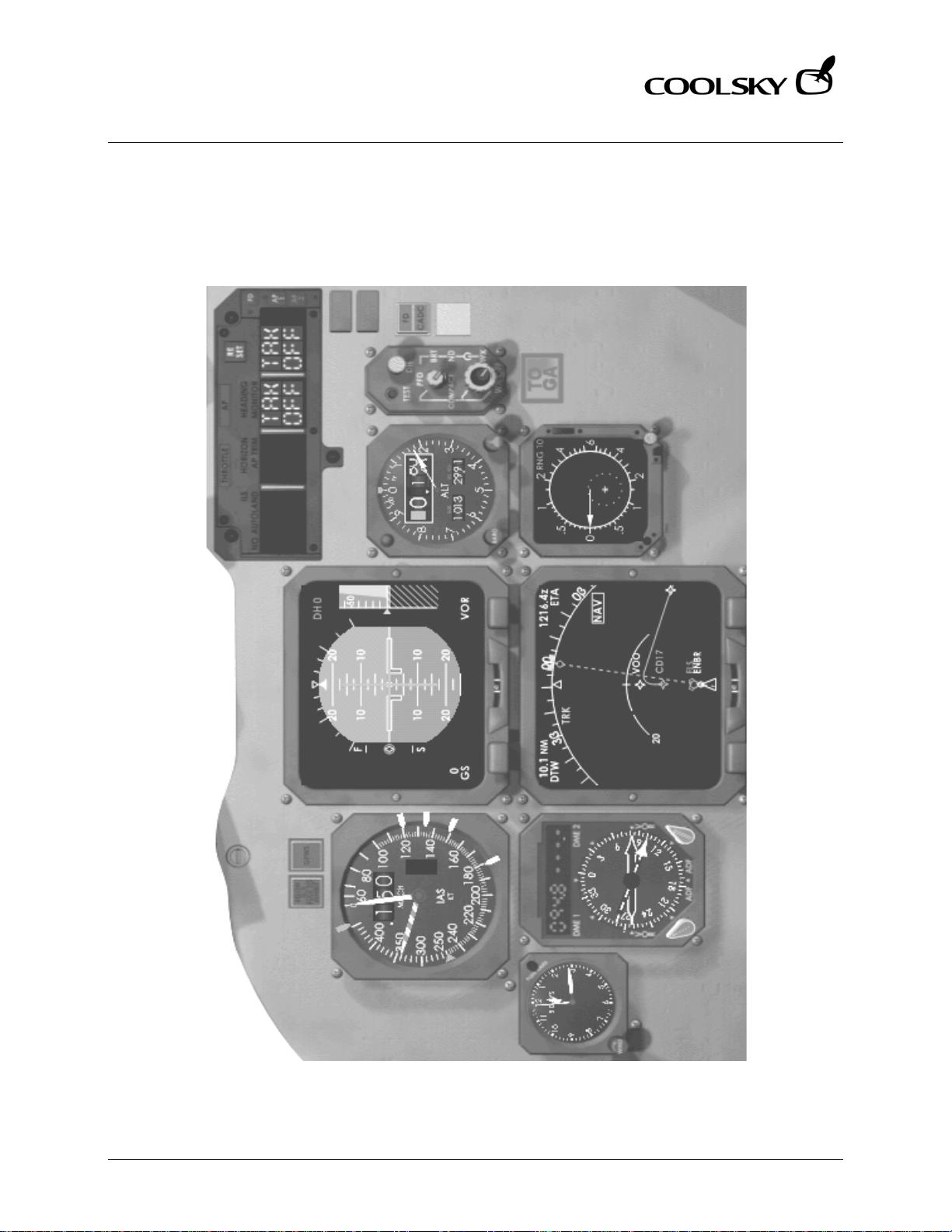
CAPTAIN’S INSTRUMENT PANEL ............................................................................................. 11
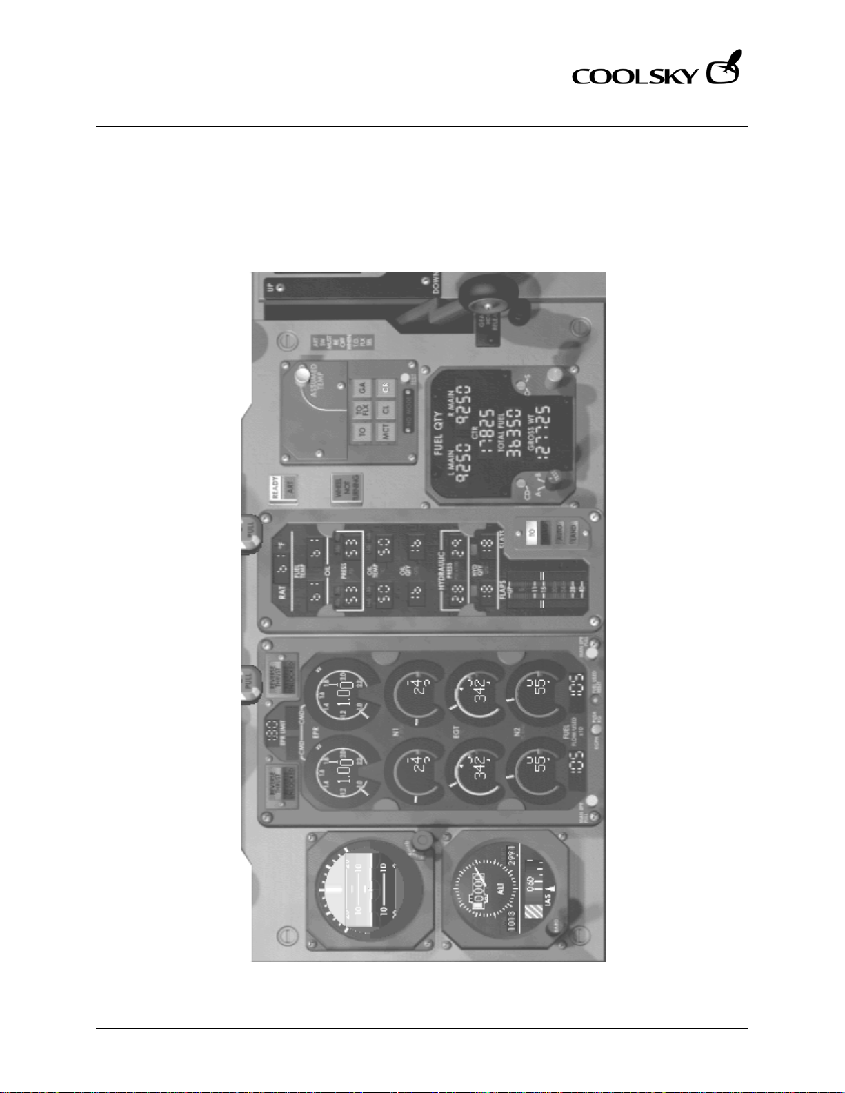
CENTER INSTRUMENT PANEL .................................................................................................. 12
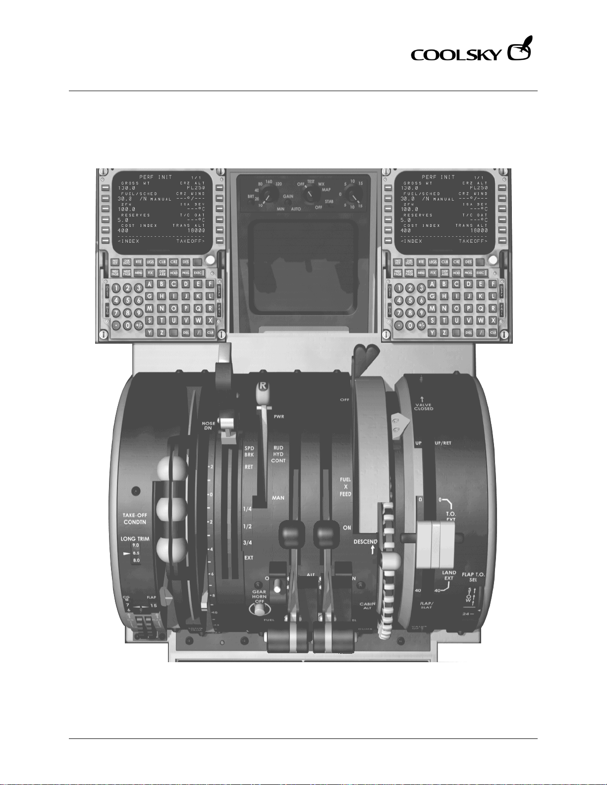
PEDESTAL (FORWARD) ............................................................................................................ 13
PEDESTAL (AFT) ........................................................................................................................ 14
SECTION 2: LIMITATIONS 0
TABLE OF CONTENTS ................................................................................................................. 1
GENERAL .................................................................................................................................... 2
AIRSPEEDS .................................................................................................................................. 3
WEIGHTS ..................................................................................................................................... 3
SECTION 3: NORMAL PROCEDURE S 0
TABLE OF CONTENTS ................................................................................................................. 1
GENERAL .................................................................................................................................... 2
NORMAL PROCEDURE CHECKLIST.......................................................................................... 3
ORIGINATION PRE-FLIGHT INSPECTION .................................................................................. 5
COCKPIT CLEAN-UP INSPECTION ......................................................................................... 13
BEFORE STARTING ENGINES ................................................................................................... 16
PRIOR TO ENGINE START OR PUSHOUT ................................................................................. 20
APU START ................................................................................................................................. 21
ENGINE START .......................................................................................................................... 23
POWER BACK FROM GATE .................................................................................................... 25
TAXI ............................................................................................................................................ 26
BEFORE TAKE-OFF .................................................................................................................... 28
TAKE-OFF .................................................................................................................................. 30
AFTER TAKE-OFF – CLIMB ........................................................................................................ 31
CRUISE ....................................................................................................................................... 33
DESCENT ................................................................................................................................... 34
BEFORE LANDING .................................................................................................................... 36
LANDING .................................................................................................................................. 37
AFTER LANDING ....................................................................................................................... 38
PARKING ................................................................................................................................... 40
Coolsky, 2018
Page 4

Super 80 Professional – AOM
TABLE OF CONTENTS
Super 80 Professional – Aircraft Operating Manual
SECTION 4: OPERATING TECHNIQUES 0
TABLE OF CONTENTS ................................................................................................................. 1
PREFACE ..................................................................................................................................... 2
TAXI .............................................................................................................................................. 2
JET BLAST ..................................................................................................................................... 3
TAKE-OFF .................................................................................................................................... 4
CLIMB .......................................................................................................................................... 4
CRUISE ......................................................................................................................................... 5
DESCENT ..................................................................................................................................... 5
HOLDING .................................................................................................................................... 6
APPROACH AND LANDING ..................................................................................................... 7
SECTION 5: EMERGENCY PROCEDURES 0
SECTION 6: AIR CONDITIONING AND PRESSURIZATION 0
TABLE OF CONTENTS ................................................................................................................. 1
GENERAL .................................................................................................................................... 2
FUNCTIONAL SCHEMATIC - PNEUMATICS .............................................................................. 3
CONTROLS AND INDICATORS ................................................................................................. 4
AIR CONDITIONING .................................................................................................................. 5
PRESSURIZATION ........................................................................................................................ 7
WARNING AND CAUTION INDICATORS ................................................................................. 9
SECTION 7: ANTI-ICE AND RAIN PROT ECTION 0
TABLE OF CONTENTS ................................................................................................................. 1
GENERAL .................................................................................................................................... 2
CONTROLS AND INDICATORS ................................................................................................. 3
WARNING AND CAUTION INDICATORS ................................................................................. 5
SECTION 8: AUTO-FLIGHT 0
TABLE OF CONTENTS ................................................................................................................. 1
GENERAL .................................................................................................................................... 2
FLIGHT DIRECTOR ...................................................................................................................... 5
AUTOTHROTTLE .......................................................................................................................... 6
ROLL MODE SELECTORS ........................................................................................................... 7
PITCH MODE SELECTORS .......................................................................................................... 8
YAW DAMPER, MACH TRIM AND ALTITUDE ADVISORY LIGHT........................................... 10
EFIS CONTROLS ........................................................................................................................ 11
FLIGHT MODE ANNUNCIATOR .............................................................................................. 12
FMA – LEGEND LIGHTS ............................................................................................................ 13
FMA – AUTOTHROTTLE WINDOW ........................................................................................... 14
FMA – ARM WINDOW ............................................................................................................. 16
FMA – ROLL WINDOW ............................................................................................................. 17
FMA – PITCH WINDOW ........................................................................................................... 19
Coolsky, 2018
Page 5

Super 80 Professional – AOM
TABLE OF CONTENTS
Super 80 Professional – Aircraft Operating Manual
SECTION 9: APU 0
TABLE OF CONTENTS ................................................................................................................. 1
GENERAL .................................................................................................................................... 2
CONTROLS AND INDICATORS ................................................................................................. 3
SECTION 10: COMMUNICATIONS 0
TABLE OF CONTENTS ................................................................................................................. 1
GENERAL .................................................................................................................................... 2
CONTROLS AND INDICATORS ................................................................................................. 3
SECTION 11: ELECTRICAL 0
TABLE OF CONTENTS ................................................................................................................. 1
GENERAL .................................................................................................................................... 2
CONTROLS AND INDICATORS ................................................................................................. 4
WARNING AND CAUTION INDICATORS ................................................................................. 7
SECTION 12: FIRE PROTECTION 0
TABLE OF CONTENTS ................................................................................................................. 1
GENERAL .................................................................................................................................... 2
CONTROLS AND INDICATORS ................................................................................................. 3
SECTION 13: FLIGHT CONTROLS 0
TABLE OF CONTENTS ................................................................................................................. 1
GENERAL .................................................................................................................................... 2
MAJOR COMPONENT LOCATION .......................................................................................... 7
LONGITUDINAL CONTROL AND TRIM ..................................................................................... 8
RUDDER CONTROL AND TRIM ............................................................................................... 11
SPEEDBRAKE/SPOILER ............................................................................................................. 12
FLAP/SLAT SYSTEM ................................................................................................................... 13
MACH TRIM AND STALL WARNING ....................................................................................... 14
WARNING AND CAUTION INDICATORS ............................................................................... 15
Coolsky, 2018
Page 6

Super 80 Professional – AOM
TABLE OF CONTENTS
Super 80 Professional – Aircraft Operating Manual
SECTION 14: FLIGHT INSTRUMENTS 0
TABLE OF CONTENTS ................................................................................................................. 1
GENERAL .................................................................................................................................... 2
AIRSPEED/MACH INDICATOR.................................................................................................. 4
CADC AND STATIC AIR SWITCHING ....................................................................................... 5
TAS/SAT INDICATOR .................................................................................................................. 6
ALTIMETER ................................................................................................................................... 7
RADIO ALTIMETER ...................................................................................................................... 8
SLIP INDICATOR ......................................................................................................................... 8
STANDBY INSTRUMENTS AND CLOCK ..................................................................................... 9
VERTICAL SPEED INDICATOR ................................................................................................. 10
PRIMARY FLIGHT DISPLAY ....................................................................................................... 11
PFD FAIL LEGENDS ................................................................................................................... 13
PFD COMPACTED MODE ....................................................................................................... 14
SECTION 15: FLIGHT MANAGEMENT 0
TABLE OF CONTENTS ................................................................................................................. 1
GENERAL .................................................................................................................................... 2
IRS MODE SELECT PANEL .......................................................................................................... 6
FMS FLIGHT GUIDANCE MODES .............................................................................................. 7
MCDU PAGE DESCRIPTION .................................................................................................... 11
FMS OPERATIONS .................................................................................................................... 40
SECTION 16: FUEL 0
TABLE OF CONTENTS ................................................................................................................. 1
GENERAL .................................................................................................................................... 2
CONTROLS AND INDICATORS ................................................................................................. 3
WARNING AND CAUTION INDICATORS ................................................................................. 6
FUEL DISTRIBUTION GUIDE......................................................................................................... 7
SECTION 17: HYDRAULICS 0
TABLE OF CONTENTS ................................................................................................................. 1
GENERAL .................................................................................................................................... 2
CONTROLS AND INDICATORS ................................................................................................. 3
WARNING AND CAUTION INDICATORS ................................................................................. 4
SECTION 18: LANDING GEAR 0
TABLE OF CONTENTS ................................................................................................................. 1
GENERAL .................................................................................................................................... 2
CONTROLS AND INDICATORS ................................................................................................. 5
WARNING AND CAUTION INDICATORS ................................................................................. 9
Coolsky, 2018
Page 7

Super 80 Professional – AOM
TABLE OF CONTENTS
Super 80 Professional – Aircraft Operating Manual
SECTION 19: MISCELLANEOUS 0
TABLE OF CONTENTS ................................................................................................................. 1
EXTERIOR LIGHTING ................................................................................................................... 2
COCKPIT LIGHTING ................................................................................................................... 3
VOICE RECORDER .................................................................................................................... 5
ELECTRONIC OVERHEAD ANNUNCIATON PANEL (EOAP) .................................................. 6
SECTION 20: NAVIGATION 0
TABLE OF CONTENTS ................................................................................................................. 1
GENERAL .................................................................................................................................... 2
VHF NAV CONTROL PANEL AND ADF CONTROL PANEL ..................................................... 3
RADIO DISTANCE MAGNETIC INDICATOR (RDMI) ............................................................... 4
NAVIGATION DISPLAY (ROSE MODE) .................................................................................... 5
NAVIGATION DISPLAY (ARC MODE) ...................................................................................... 6
NAVIGATION DISPLAY (MAP MODE) ..................................................................................... 8
NAVIGATION DISPLAY (PLAN MODE) .................................................................................... 9
MODE SELECTOR CONTROL PANEL & MAG/TRUE LIGHT .................................................. 10
SECTION 21: OXYGEN 0
TABLE OF CONTENTS ................................................................................................................. 1
GENERAL .................................................................................................................................... 2
CONTROLS AND INDICATORS ................................................................................................. 3
SECTION 22: POWER PLANT 0
TABLE OF CONTENTS ................................................................................................................. 1
GENERAL .................................................................................................................................... 2
CONTROLS AND INDICATORS ................................................................................................. 5
WARNING AND CAUTION INDICATORS ............................................................................... 11
SECTION 23: PERFORMANCE 0
TABLE OF CONTENTS ................................................................................................................. 1
GENERAL .................................................................................................................................... 2
TAKE-OFF .................................................................................................................................... 4
CLIMB ........................................................................................................................................ 10
CRUISE ....................................................................................................................................... 12
ARRIVAL .................................................................................................................................... 21
MISCELLANEOUS ..................................................................................................................... 25
SECTION 24: WARNING SYSTEMS 0
TABLE OF CONTENTS ................................................................................................................. 1
RADAR ........................................................................................................................................ 2
GROUND PROXIMITY WARNING SYSTEM ............................................................................... 5
WARNING AND CAUTION INDICATORS ................................................................................. 9
TCAS/VSI ................................................................................................................................... 10
Coolsky, 2018
Page 8

Super 80 Professional – AOM
DESCRIPTION
Section 1 Page 0
Super 80 Professional – Aircraft Operating Manual
SECTION 1
DESCRIPTION
Coolsky, 2018
Page 9

Super 80 Professional – AOM
DESCRIPTION
Section 1 Page 1
Super 80 Professional – Aircraft Operating Manual
TABLE OF CONTENTS
SECTION 1: DESCRIPTION 0
TABLE OF CONTENTS ................................................................................................................. 1
DIMENSIONS ............................................................................................................................... 2
TURNING RADIUS ....................................................................................................................... 4
COMPARTMENTS ....................................................................................................................... 5
INTERIOR ARRANGEMENT ........................................................................................................ 6
COCKPIT ARRANGEMENT ........................................................................................................ 7
OVERHEAD PANEL (AFT) .......................................................................................................... 8
OVERHEAD PANEL (FORWARD) .............................................................................................. 9
GLARESHIELD AND UPPER INSTRUMENT PANEL ................................................................... 10
CAPTAIN’S INSTRUMENT PANEL ............................................................................................. 11
CENTER INSTRUMENT PANEL .................................................................................................. 12
PEDESTAL (FORWARD) ............................................................................................................ 13
PEDESTAL (AFT) ........................................................................................................................ 14
Coolsky, 2018
Page 10
Super 80 Professional – AOM
DESCRIPTION
Section 1 Page 2
Super 80 Professional – Aircraft Operating Manual
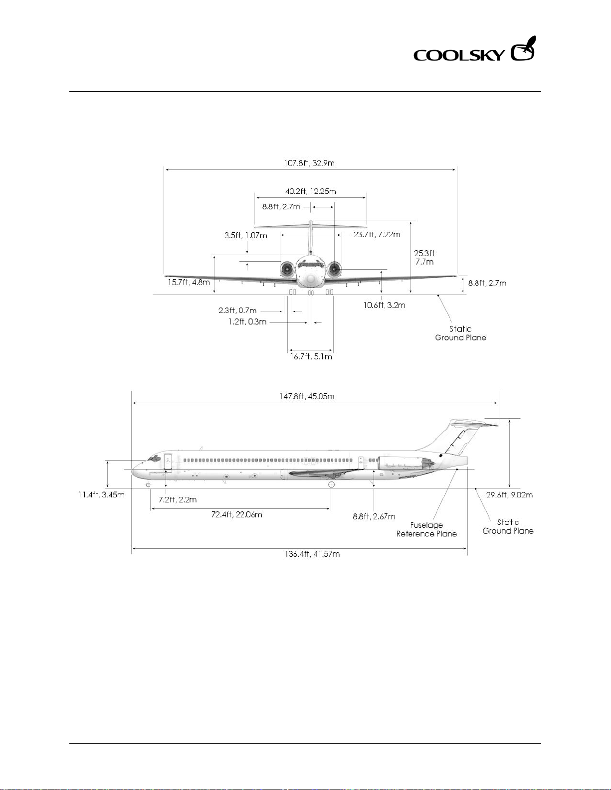
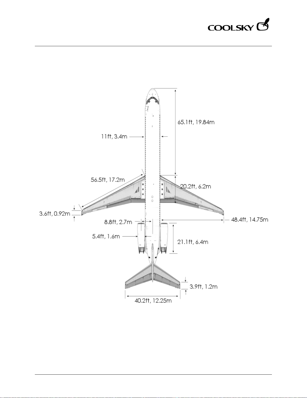
DIMENSIONS
Coolsky, 2018
Page 11
Super 80 Professional – AOM
DESCRIPTION
Section 1 Page 3
Super 80 Professional – Aircraft Operating Manual
Coolsky, 2018
Page 12
Super 80 Professional – AOM
DESCRIPTION
Section 1 Page 4
Super 80 Professional – Aircraft Operating Manual
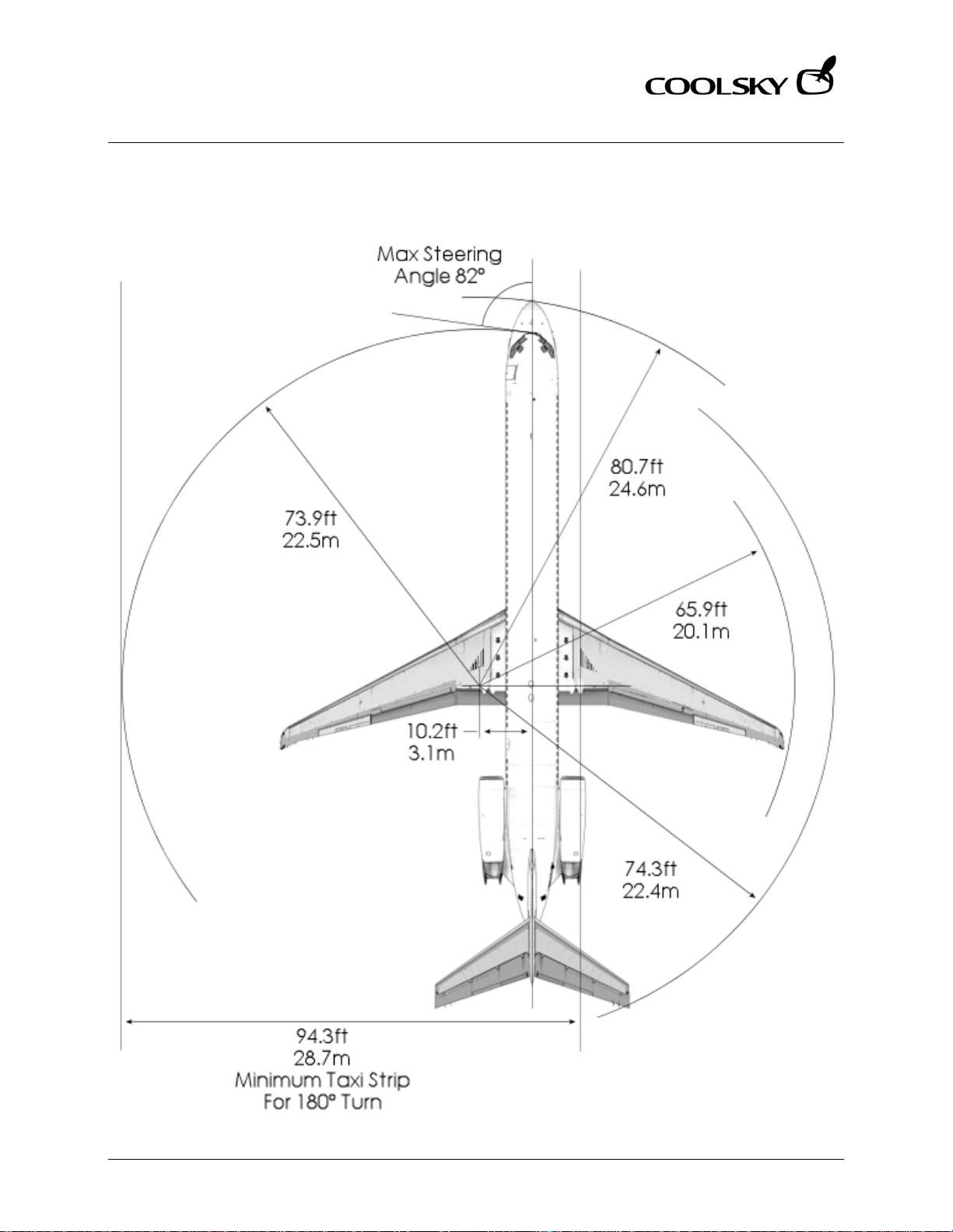
TURNING RADIUS
Coolsky, 2018
Page 13
Super 80 Professional – AOM
DESCRIPTION
Section 1 Page 5
Super 80 Professional – Aircraft Operating Manual
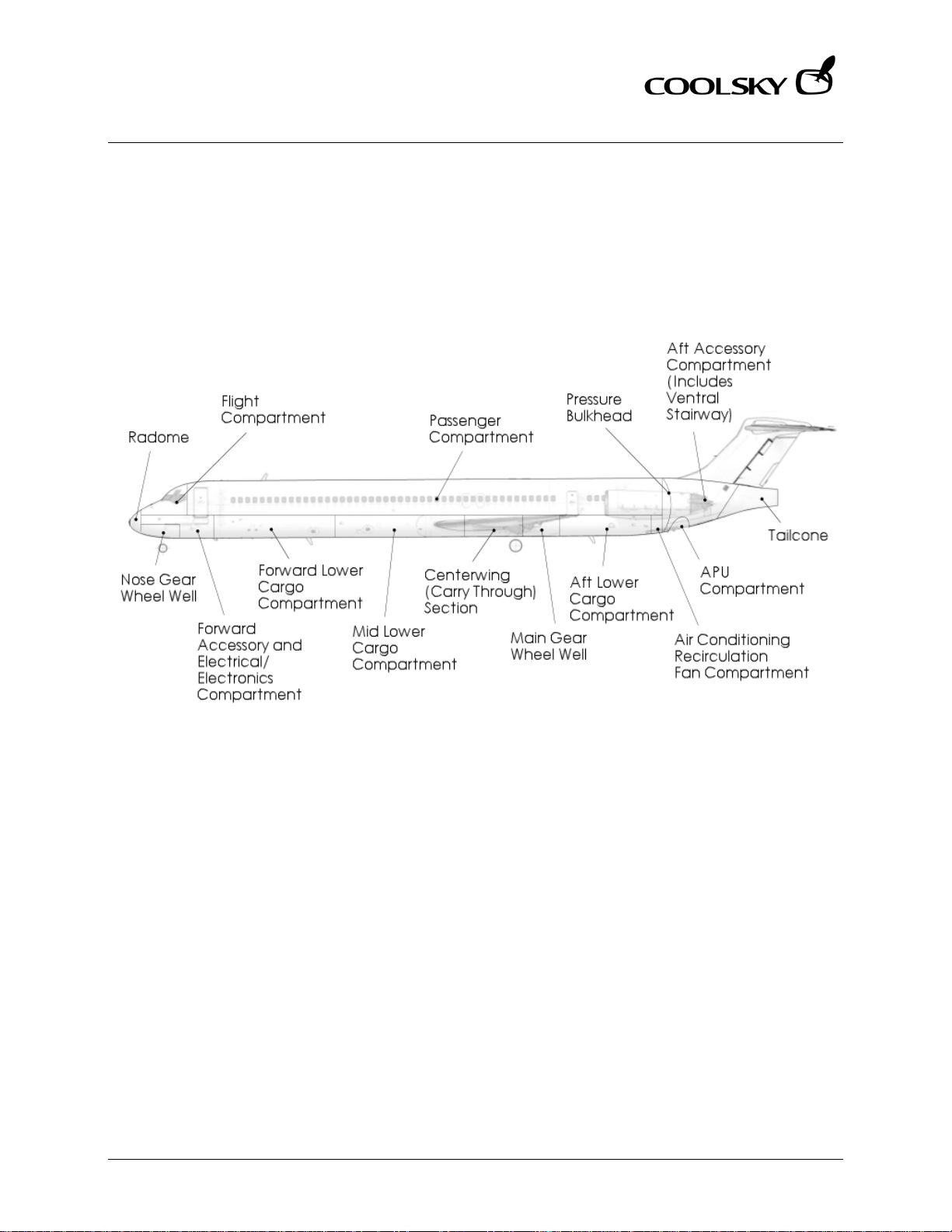
COMPARTMENTS
Coolsky, 2018
Page 14
Super 80 Professional – AOM
DESCRIPTION
Section 1 Page 6
Super 80 Professional – Aircraft Operating Manual
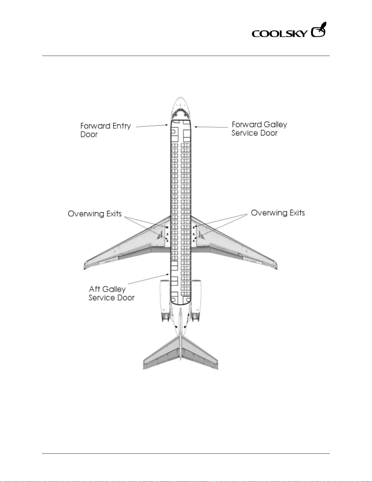
INTERIOR ARRANGEMENT
Coolsky, 2018
Page 15
Super 80 Professional – AOM
DESCRIPTION
Section 1 Page 7
Super 80 Professional – Aircraft Operating Manual
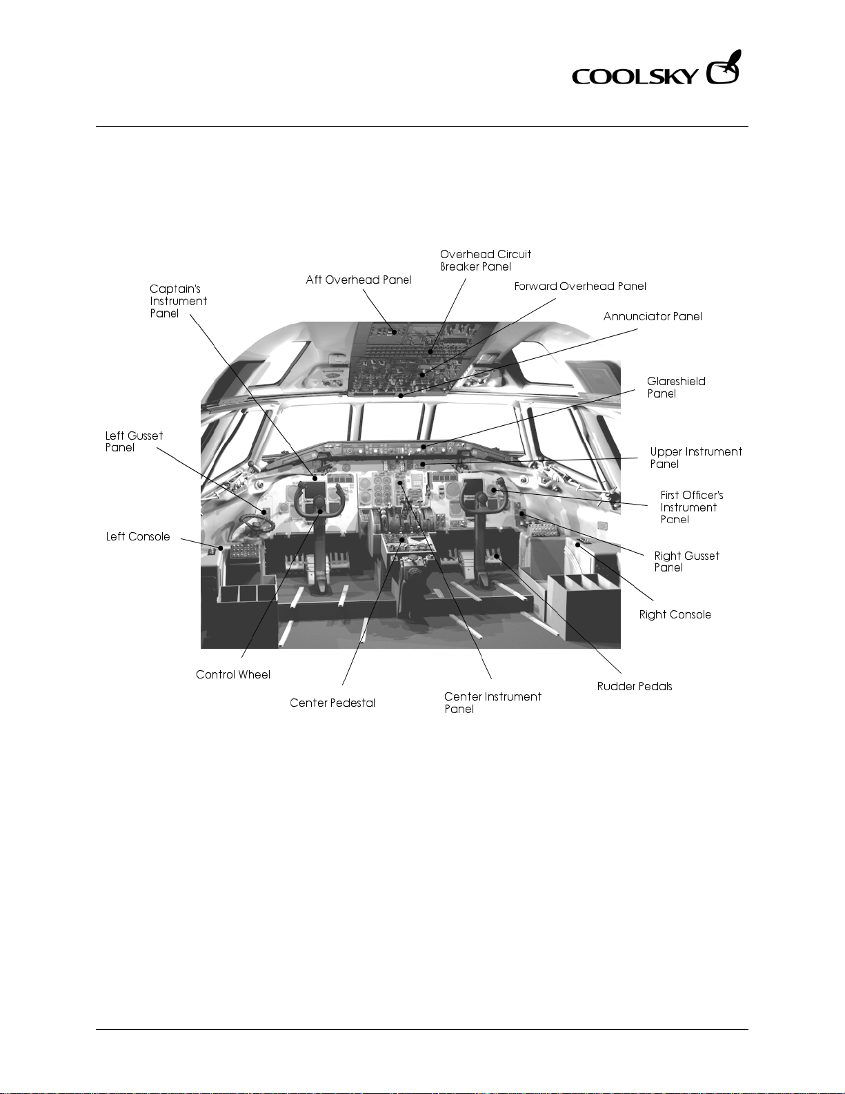
COCKPIT ARRANGEMENT
Coolsky, 2018
Page 16
Super 80 Professional – AOM
DESCRIPTION
Section 1 Page 8
Super 80 Professional – Aircraft Operating Manual
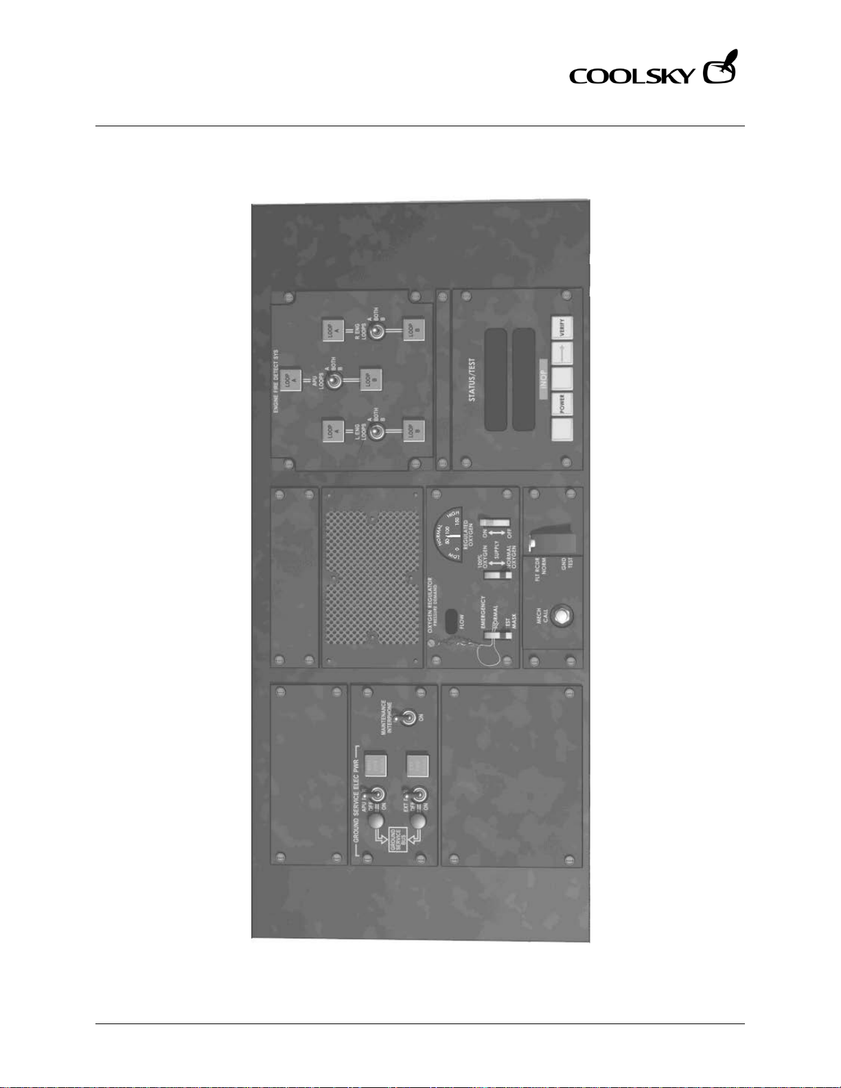
OVERHEAD PANEL (AFT)
Coolsky, 2018
Page 17
Super 80 Professional – AOM
DESCRIPTION
Section 1 Page 9
Super 80 Professional – Aircraft Operating Manual
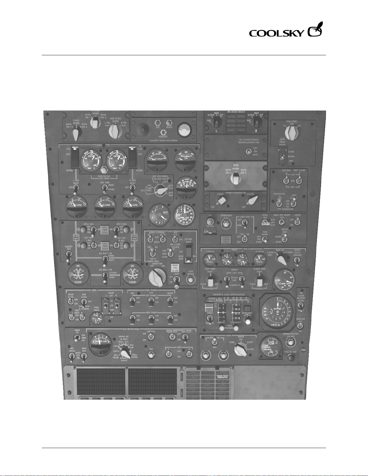
OVERHEAD PANEL (FORWARD)
Coolsky, 2018
Page 18
Super 80 Professional – AOM
DESCRIPTION
Section 1 Page 10
Super 80 Professional – Aircraft Operating Manual
GLARESHIELD AND UPPER INSTRUMENT PANE L
Coolsky, 2018
Page 19
Super 80 Professional – AOM
DESCRIPTION
Section 1 Page 11
Super 80 Professional – Aircraft Operating Manual
CAPTAIN’S INSTRUMENT PANEL
Coolsky, 2018
Page 20
Super 80 Professional – AOM
DESCRIPTION
Section 1 Page 12
Super 80 Professional – Aircraft Operating Manual
CENTER INSTRUMENT PANEL
Coolsky, 2018
Page 21
Super 80 Professional – AOM
DESCRIPTION
Section 1 Page 13
Super 80 Professional – Aircraft Operating Manual
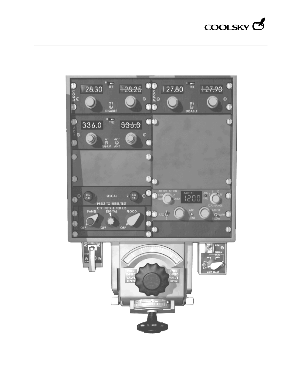
PEDESTAL (FORWARD)
Coolsky, 2018
Page 22
Super 80 Professional – AOM
DESCRIPTION
Section 1 Page 14
Super 80 Professional – Aircraft Operating Manual
PEDESTAL (AFT)
Coolsky, 2018
Page 23

Super 80 Professional – AOM
LIMITATIONS
Section 2 Page 0
Super 80 Professional – Aircraft Operating Manual
SECTION 2
LIMITATIONS
Coolsky, 2018
Page 24

Super 80 Professional – AOM
LIMITATIONS
Section 2 Page 1
Super 80 Professional – Aircraft Operating Manual
TABLE OF CONTENTS
SECTION 2: LIMITATIONS 0
TABLE OF CONTENTS ................................................................................................................. 1
GENERAL .................................................................................................................................... 2
AIRSPEEDS .................................................................................................................................. 3
WEIGHTS ..................................................................................................................................... 3
Coolsky, 2018
Page 25
Super 80 Professional – AOM
LIMITATIONS
Section 2 Page 2
Super 80 Professional – Aircraft Operating Manual
GENERAL
Flight Maneuvering Load Acceleration Limits +2.5g to -1.0g
Operational Limits
Runway Slope +1.7% to -2.0%
Limiting Tailwind Component 10 knots
Crosswind Values (Ta ke-Off and Landing)
Maximum demonstrated crosswind component is 30kts. This is not a limitation. However,
components at or near 30 knots with higher gusts should be considered operationally
unacceptable.
Minimum Take-Off and Landing Altitude
Maximum Take-Off and Landing Altitude
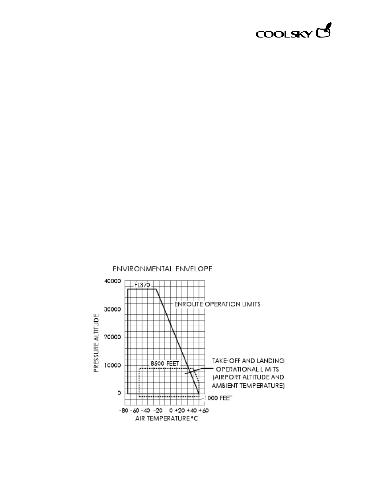
Take-Off and Landing Temperature Limitations
Minimum -65°F/-54°C
Maximum +122°F/+50°C
Environmental Envelope
-1,000 ft
8,500 ft
Coolsky, 2018
Page 26

Super 80 Professional – AOM
LIMITATIONS
Section 2 Page 3
Super 80 Professional – Aircraft Operating Manual
AIRSPEEDS
Maximum Operating Airspeed
(VMO/M
Landing Gear Operation
(VLO/M
Landing Gear Extended
(VLE/MLE)
Flap Placard Speeds
(V
FE/MFE
0°-13° 280kts/.57M
14°-20° 240kts/.57M
21°-25° 220kts/.57M
26°-30° 200kts/.57M
31°-40° 195kts/.57M
Slats Extended
Mid position 280kts/.57M
Full extended 240kts/.57M
Turbulence Penetration Speed
) M
MO
) Retraction – 250kts/.70M
LO
300kts/.70M
) FLAP POSITION LIMITING SPEED
SLATS POSITION LIMITING SPEED
VMO – 340kts
– .84M (above Mach/IAS crossover altitude)
MO
Extension – 300kts/.70M
275-285kts or .75-.79M, whichever is lower
Maximum Ramp Weight 150,500 lbs
Maximum Take-Off Weight 149,500 lbs
This is maximum allowable gross weight for the aircraft at brake release, just prior to
commencing take-off roll.
Maximum Landing Weight 130,000 lbs
Landings at weights exceeding the Maximum Landing Weight are authorized. Special
procedures apply for overweight landings. Maintenance reports and inspections are
required following an overweight landing.
Maximum Zero Fuel Weight 122,000 lbs
WEIGHTS
Coolsky, 2018
Page 27

Super 80 Professional – AOM
NORMAL PROCEDURE S
Section 3 Page 0
Super 80 Professional – Aircraft Operating Manual
SECTION 3
NORMAL PROCEDURES
Coolsky, 2018
Page 28

Super 80 Professional – AOM
NORMAL PROCEDURE S
Section 3 Page 1
Super 80 Professional – Aircraft Operating Manual
TABLE OF CONTENTS
SECTION 3: NORMAL PROCEDURES 0
TABLE OF CONTENTS ................................................................................................................. 1
GENERAL .................................................................................................................................... 2
NORMAL PROCEDURE CHECKLIST.......................................................................................... 3
ORIGINATION PRE-FLIGHT INSPECTION .................................................................................. 5
COCKPIT CLEAN-UP INSPECTION ......................................................................................... 13
BEFORE STARTING ENGINES ................................................................................................... 16
PRIOR TO ENGINE START OR PUSHOUT ................................................................................. 20
APU START ................................................................................................................................. 21
ENGINE START .......................................................................................................................... 23
POWER BACK FROM GATE .................................................................................................... 25
TAXI ............................................................................................................................................ 26
BEFORE TAKE-OFF .................................................................................................................... 28
TAKE-OFF .................................................................................................................................. 30
AFTER TAKE-OFF – CLIMB ........................................................................................................ 31
CRUISE ....................................................................................................................................... 33
DESCENT ................................................................................................................................... 34
BEFORE LANDING .................................................................................................................... 36
LANDING .................................................................................................................................. 37
AFTER LANDING ....................................................................................................................... 38
PARKING ................................................................................................................................... 40
Coolsky, 2018
Page 29

Super 80 Professional – AOM
NORMAL PROCEDURE S
Section 3 Page 2
Super 80 Professional – Aircraft Operating Manual
GENERAL
Normal Procedures Checklist
The Normal Procedure Checklists are used to
insure that all important safety items have
been accomplished.
The items in the Checklist cannot be
considered accomplished until all of the
expanded procedures associated with that
item have been accomplished.
Crew Duties
Normally crew duties are divided between
the Captain and First Officer during ground
operations and between pilot-flying and
pilot-not-flying during flight. The Captain is
responsible for ensuring that all normal
procedure checklists are accomplished at
the proper time.
Normally the pilot-not-flying will accomplish
the appropriate checklist and notify the
pilot-flying when the checklist has been
completed.
Auto-Flight/Altitude Clearance
Procedures
Normally when the autopilot is engaged, the
pilot-flying will control the Flight Guidance
panel. When the autopilot is not engaged,
the pilot-flying will normally call for changes
to be made to the Flight Guidance panel by
the pilot-not-flying.
Both pilots should be aware of all
communications traffic and clearances.
Traffic Watch
Both crew members shall maintain traffic
watch during all phases of flight.
Cabin Door Operation
The cabin door(s) shall be closed for
departure and opened on arrival by the
Gate Agent, using the cabin door exterior
control. Except for emergencies, do not
request the Flight Attendant to open or
close the door(s). Call the Gate Agent.
Note: It is perfectly normal to have a gap
between the cabin door and aircraft when
the door is closed and the aircraft is
unpressurized. This allows for negative
pressure relief. The doors will become flush
with the airframe when the aircraft
pressurizes during the take-off roll.
To open and close the doors of this aircraft
use the following keyboard key
combinations:
• Main Exit: SHIFT-E, 1
• Forward air stairs: SHIFT-E, 2
• Ventral (aft) air stairs: SHIFT-E, 3
Press SHIFT and E together, then release
them and quickly hit 1, 2 or 3.
Anti-Collision Lights
The Anti-Collision lights shall be ON when the
engines are about to best started or are
running, and anytime the airplane is in
motion, taxi or tow.
Coolsky, 2018
Page 30

Super 80 Professional – AOM
NORMAL PROCEDURE S
Section 3 Page 3
Super 80 Professional – Aircraft Operating Manual
NORMAL PROCEDURE CHECKLIST
BEFORE STARTING ENGINES
LOGBOOK ............................................................... CHECKED
RUDDER PEDALS AND
SEATS ..................................... ADJUSTED AND LOCKED
WINDOWS ......................................... CLOSED AND LOCKED
O2 PANELS/INTERPHONE/
O2 PRESSURE .................................. SET AND CHECKED
EMERGENCY LIGHTS .................................................. ARMED
PROBE HEAT ........................................ CHECK ED AND CAPT
WINDSHIELD ANTI-ICE ....................................................... ON
ANTI-SKID ........................................................................... OFF
PRESSURIZATION .................................... AUTO (UP) AND SET
AIR COND SHUTOFF ...................................................... AUTO
FLIGHT GUIDANCE PANEL ..................... SET AND CHECKED
FLT INSTR/SWITCHES/BUGS ........ SET AND CROSSCHECKED
FUEL PANEL/QUANTITY AND
DISTRIBUTION ...................... SET AND CROSSCH E CKE D
GE AR HANDLE AND LI GHTS ................. DOWN AND GREEN
TRANSPONDER ................................................................... SET
STABILIZER TRIM ................................................................... SET
SPOILER LEVER ................................................................... RET
THROTTLES .................................................................. CLOSED
TAKE-OFF WARNI NG .............................................. CHECKED
FUEL LEVERS ...................................................................... OFF
FLAPS/SLATS ................................................... UP/RETRACTED
AILERON/RUDD ER TRIM ...................................... ZERO/ZERO
PARKING BRAKE/PRESSURE .....................PARKED/NORMAL
SHOULDER HARNESSES ..................................................... ON
FLIGHT FORMS......................................................... CHECKED
NO SMO KING SIGNS ......................................................... ON
FIVE M INUTES PRIOR TO D EP ART U RE
SEAT BELT SIGNS ................................................................. ON
PRIOR TO ENGINE START OR PUSH OUT
GALLEY POWER ................................................................ OFF
ENGINE IGNITION ...................................................... CONTIN
FUEL PUMPS ........................................................................ ON
AUX HYDRAULIC PUMP ..................................................... ON
ANTI-COLLITION/EXTERIOR LIGHTS ......... ON/AS REQUIRED
DOOR ANNUNCIATOR .................................................... OUT
AIR CONDITIONIN G SUPP LY SWITCHES ......................... OFF
TAXI
BEFORE TAX I OR POWERBACK
GALLEY POWER .................................................................. ON
ENGINE ANTI-ICE .............................................. AS REQUIRED
HYDRAULIC PUMPS ........................... CHECKED AND HI/ON
TAXI
APU .................................................................... AS REQUIRED
PNEU X-FE ED (One engine taxi) ............ L CLOSED/R OPEN
ANTI-SKID (After leaving ramp area) ........................... ARM
R ENG (One engine taxi) ................................... SHUTDOWN
FLIGHT CONTROLS ................................................. CHECKED
FGS .......................................................................... T/O MODE
TRANSPONDER .................................................................... TA
BEFORE TAKE-OFF (Mechanical Checklist)
FLT INST & BUGS ...................................... SET AND CHECKED
ANTI-ICE ............................................................. AS REQUIRED
FL APS AND SLATS .................................................... TAKE-OFF
STAB TRIM ............................................................................ SET
APU/PNEU X-FD’S ............................. AS REQUIRED/CLOSED
ANTI-SKID/ABS ................... ARMED/TAKE-OFF AN D ARME D
SPOILER LEVER ............................................................ ARMED
TO PA/PACKS .............................. COMPLETE/AS REQUIRED
ANNUNCIATOR LIGHTS .......................................... CHECKED
NOSE LIGHTS ................................................................ BRIGHT
AFTER TAKE-OFF – CLIMB
GEAR ....................................................... UP AND NO LIGHTS
SPOILER LEVER ....................................................... DISARMED
AUTO BRAKES ....................................... O FF AND DISARMED
FL APS AND SLATS ............................................ UP/NO LIGHTS
PR ESSURIZATI ON AND AIR COND ........................ CHECKED
TRANSPONDER .............................................................. TA/RA
10,000FT MSL
ENGINE IGNITION ............................................. AS REQUIRED
FUEL SYSTEM ............................................................ CHECKED
STERILE COCKPIT ............................................. CABIN CHIME
ALTIMETERS .............................. RESET AND CROSSCHE CKED
HYDRAULIC PUMPS ................................................. LOW/OFF
18,000FT MSL
EXTERIOR LIGHTS .............................................. AS REQUIRED
ALTIMETERS .............................. RESET AND CROSSCHE CKED
Coolsky, 2018
Page 31

Super 80 Professional – AOM
NORMAL PROCEDURE S
Section 3 Page 4
Super 80 Professional – Aircraft Operating Manual
CRUISE
ENG SYNC .......................................................................... ON
FIRST FLIGHT OF DAY ITEMS ................................... CHECKED
DELAY CODES IN ACARS ................................ AS REQUIRED
DESCENT
LANDI NG DAT A ..................................................... PREPARED
PRESSURIZATION ..................................... SET AND CHECKED
ENG SYNC ......................................................................... OFF
ENGINE IGNITION ...................................................... CONTIN
EN GIN E AND AIRF OIL ANTI-ICE ....................... AS REQUIRE D
WINDSHIELD ANTI-FOG .................................... AS REQUIRED
SHOULDER HARNESSES ..................................................... ON
DESCENDING THRU FL180 OR LEAVING CRUISE ALTITUDE,
WHICHEVER IS LOWER
EXTERIOR LIGHTS ............................................... AS REQUIRED
ALTIMETERS .............................. RESET AND CROSSCHE CKED
HYDRAULIC PANEL .................................... HI/ON/CHECKED
10,000FT MSL
STERILE COCKPIT ............................................. CABIN CHIME
BEFORE LANDING (Mechanical Checklist)
ALTIMETERS .............................. RESET AND CROSSCHE CKED
FLT INST & BUGS .......................... SET AND CROSSCHECKED
SEAT BELT/NO SMK ............................................................ ON
GEAR................................................... DOWN, THREE GREEN
SPOILER LEVER ............................................................ ARMED
AUTO BRAKES .................................................... AS REQUIRED
FL APS & SLATS ................................................................ LAND
ANNUNCIATOR LIGHTS .......................................... CHECKED
AFTER LANDING – TAXI
AUTOPILOT AND AUTOTHROTTLE SWITCHES .................. OFF
LANDING LIGHTS ............................................................... OFF
SPOILER LEVER .................................................................... RET
AUTO BRAKES .................................................... OFF/DISARM
PNEU XFEED (One engine taxi) ............. R OPEN/L CLOSED
FLAPS/SLATS ................................................... UP/RETRACTED
RADAR ................................................................................ OFF
TRANSPONDER ................................................................. STBY
ANTI-SKID ............................................................................ OFF
BRAKE PRESSURE .................................................... MONITOR
APU .................................................................... AS REQUIRED
R ENG (One engine taxi) ................................... SHUTDOWN
PARKING
BRAKES ....................................................................... PARKED
SEAT BELT SIGN .................................................................. OFF
PNEU XFEED VALVES ..................................................... OPEN
APU OR EXTERNAL POWER ............................... ESTABLISHED
FUEL LEVERS ....................................................................... OFF
ANTI-COLLISION/EXTERIOR LIGH TS......... OFF/AS REQUIRED
ENGINE IGNITION .............................................................. OFF
FUEL PUMPS........................................................................ OFF
EMERGENCY LIGHTS ......................................................... OFF
PROBE HEAT ....................................................................... OFF
ANTI-ICE .............................................................................. OFF
AIR CONDITIONIN G ......................................... AS REQUIRED
OIL/HYD/O2 QUANTITIES ....................................... CHECKED
ARRIVAL REPORT .............................................. AS REQUIRED
LOGBOOK ........................................................... COMPLETED
FD SWITCHES OFF .............................................................. OFF
O2 PANEL SUPPLY LEVERS ................................................ OFF
COCKPIT LIGHTS ............................................... AS REQUIRED
ALL PASSENGERS HAVE DEPLANED
GALLEY POWER ................................................................. OFF
AIR CONDITIONIN G .......................................................... OFF
APU .................................................................... AS REQUIRED
BATTERY SWITCH ........................................................ ON/OFF
POST FLIGHT INSPECTION ................................ AS REQUIRED
Coolsky, 2018
Page 32

Super 80 Professional – AOM
NORMAL PROCEDURE S
Section 3 Page 5
Super 80 Professional – Aircraft Operating Manual
ORIGINATION PRE-FLIGHT INS PECTI O N
ORIGINATION PRE-FLIGHT INSPECTION (Procedure)
The Origination Pre-Flight Inspection is accomplished on the first origination flight of the day
for the aircraft and anytime the condition of the aircraft is in doubt.
WALK-AROUND INSPECTION ...................................................................................... COMPLETE
1. Not simulated.
COCKPIT SAFETY INSPECTION
BATTERY SWITCH ....................................................................................................................... ON
2. Set the battery switch to the ON position.
COCKPIT LIGHTS ...................................................................................................... AS REQUIRED
3. Set the Cockpit Flood light switch to OFF, or as required.
4. Turn on the Center Instrument & Pedestal Digital lights.
5. Turn on the Instrument Panel Digital lights.
6. Turn on the Flight Guidance Control Panel Digital lights.
HYDRAULIC PANEL ............................................................................................................ CHECK
7. Set the Transfer Pump switch to OFF.
8. Set both Engine Pump switches to HI.
9. Set the Auxiliary Pump switch to OFF.
GEAR HANDLE .................................................................................................................... DOWN
10. Confirm that the gear handle is down and that all the three green gear lights are on.
CIRCUIT BREAKERS ............................................................................................................ CHECK
11. Not simulated.
COCKPIT INITIAL PREPARATION
APU PWR and EXT PWR ........................................................................................................... OFF
12. Set the APU PWR switch to OFF.
13. Set the EXT PWR switch to OFF.
14. Note: The APU PWR and EXT PWR switches on the Ground Service Elec Pwr Panel must be
OFF before connecting APU or External Power to main AC buses.
APU (When required) .......................................................................................................... START
15. Please refer to STARTING APU Procedure guide on how to start the APU.
EMERGENCY LIGHTS.............................................................................................................. ARM
16. Set the EMER LTS switch to ARM.
GALLEY POWER ........................................................................................................................ ON
17. Set the Galley Power switch to ON.
Coolsky, 2018
Page 33

Super 80 Professional – AOM
NORMAL PROCEDURE S
Section 3 Page 6
Super 80 Professional – Aircraft Operating Manual
CABIN ALT CONTROL LEVER/POSITION INDICATOR .................................. AUTO/VALVE OPEN
18. Check that the CABIN ALT Control Lever is in the AUTO (up) position (Yellow handle, not
the wheel).
19. Check that the outflow valve indicator indicates VALVE OPEN. Full forward indicates
valve closed, full aft indicates valve fully open. Note: If the valve is only partially open,
that is ok.
PNEUMATICS AND AIR CONDITIONING ................................................................. ESTABLISHED
20. Set both Pneumatic X-Feed handles to the OPEN (up) position.
21. Check that the APU AIR switch is set to ON or COLDER.
22. Set both Air Conditioning Supply switches to AUTO.
23. Set the Air Conditioning Recirculation Fan to AUTO.
24. Set the CKPT TEMP selector to AUTO.
25. Set the CABIN TEMP selector to AUTO.
26. Set the AIR COND SHUTOFF switch to AUTO.
27. Set the RAM AIR switch to OFF.
EXTERIOR LIGHTS ................................................................................................... CHECK LIGHTS
28. Check the exterior lights of the aircraft. (Not simulated in the panel)
FLAP HANDLE/I NDICATOR ................................................................................................. AGREE
29. Make sure the flaps/slats handle is in the UP/RET position.
30. Check that the flap/slat handle and indicator agree.
ANTI-SKID ................................................................................................................ TEST AND OFF
31. Set the ANTI-SKID switch to ARM.
32. Hold the ANTI-SKID TEST CHK switch to TEST. Check that all four anti-skid lights come on.
33. Set the ANTI-SKID switch back to OFF.
PARKING BRAKE ............................................................................................................... PARKED
34. The parking brake should be on. (Raised position)
35. Check that the Parking Brake light is on.
36. Check that the Brake Pressure gauge reads above the red band.
SHOULDER HARNESSES ...................................................................................................... CHECK
37. Check the condition of the shoulder harnesses. (Not simulated)
LOGBOOK .......................................................................................................................... CHECK
38. Check the aircraft papers. (Not simulated)
CHECKLISTS ........................................................................................................ CHEC K ABOARD
39. Make sure you have all applicable checklists onboard with you.
COCKPIT AREA INSPECTIO N
CREW LIFE VESTS, O2 MASKS, SMOKE GOOGLES ........................................... CHECK ABOAR D
40. Not simulated.
Coolsky, 2018
Page 34

Super 80 Professional – AOM
NORMAL PROCEDURE S
Section 3 Page 7
Super 80 Professional – Aircraft Operating Manual
FLIGHT CREW OXYGEN SUPPLY CYLINDER ...................................................................... CHECK
41. Not simulated.
PASS OXY MASK............................................................................................ NORM (GUARDED)
42. Not simulated.
PROTECTIVE BREATING EQUIPMENT ................................................................................. CHECK
43. Not simulated.
COCKPIT EMERGENCY EQUIPMENT ................................................................. CHECK ABO ARD
44. Not simulated.
SPARE BULB KIT .................................................................................................................. CHECK
45. Not simulated.
FINAL COCKPIT PREPARATION
MAINTENANCE INTERPHONE .................................................................................................. OFF
46. Set the Maintenance Interphone switch to OFF.
FLIGHT RECORDER ...................................................................................................... TEST/NORM
47. Open the guard and set the Flight Recorder Test switch to TEST.
48. If the FLIGHT RECORDER OFF light stays off, the Flight Recorder operates properly.
49. Set the Flight Recorder Test switch back to NORM and put the guard back on.
FD CMD ........................................................................................................................... NORMAL
50. Set the FD CMD switch to NORM.
CADC .............................................................................................................................. NORMAL
51. Set the CADC switch to NORM.
VERT GYRO ..................................................................................................................... NORMAL
52. Set the VERT GYRO switch to NORM.
IRS ............................................................................................................................................NAV
53. Set both IRS mode select switches to NAV.
COCKPIT VOICE RECORDER............................................................................................. CHECK
54. Press the Cockpit Voice Recorder Test switch.
55. Observe the TEST MONITOR METER as a test signal is being sent to the Voice Recorder. No
reading on the meter indicates a failure.
ELECTRICAL SYSTEM .......................................................................................................... CHECK
56. Check that both CSD switches are guarded.
57. Set the L GEN and R GEN switches to RESET and then back to ON.
58. Set the AC BUS X TIE switch to AUTO.
59. Set the DC BUS X TIE switch to OPEN.
Coolsky, 2018
Page 35

Super 80 Professional – AOM
NORMAL PROCEDURE S
Section 3 Page 8
Super 80 Professional – Aircraft Operating Manual
EMERGENCY POWER ......................................................................................... CHECK AND OFF
60. Set the Emergency Power switch to ON.
61. Check that EMER PWR IN USE light comes on.
62. Set the Emergency Power switch back to OFF.
WING TANK FUEL PUMPS ......................................................................................................... OFF
63. Turn off all, left and right, wing tank fuel pumps. If a pump is being used for APU operation,
leave it on.
CENTER TANK FUEL PUMPS ................................................................................................ CHECK
64. Turn off fuel pump used for APU operation.
65. Check each of the center tank fuel pumps individually, checking that both the L and R
INLET FUEL PRESS LOW lights go out when each pump is turned on and comes back on
when the pump is turned off. Note: The Start Pump should be off.
66. Turn back on fuel pump used for APU operation.
IGNITION .................................................................................................................................. OFF
67. Set the Ignition switch to OFF.
FUEL HEAT ................................................................................................................................. OFF
68. Set both FUEL HEAT switches to OFF.
START SWITCHES (L & R) .......................................................................................................... OFF
69. Set both engine start switches to OFF. (Guarded position)
NO SMOKING ........................................................................................................................... ON
70. Set the NO SMOK switch to ON.
SEAT BELT .................................................................................................................................. OFF
71. Set the SEAT BELT switch to OFF.
PROBE HEAT .................................................................................................... CHECK AND CAPT
72. Rotate the METER SEL & HEAT switch to all positions and check for a reading on the
HEATER CUR gauge (except for RAT PROBE position) and that the PITOT/STALL HEATER OFF
light remains out.
AIR FOIL ANTI-ICE.................................................................................................................... OFF
73. Set the Air Foil Anti-ice switch to OFF.
WINDSHIELD A NT I-FOG ........................................................................................................... OFF
74. Set the Windshield Anti-Fog switch to OFF.
WINDSHIELD A NT I-ICE .............................................................................................................. ON
75. Set the Windshield Anti-Ice switch to ON. Note: If the windshield have been cold soaked
overnight, they may require up to 30 minutes to warm up thoroughly.
Coolsky, 2018
Page 36

Super 80 Professional – AOM
NORMAL PROCEDURE S
Section 3 Page 9
Super 80 Professional – Aircraft Operating Manual
ENGINE ANTI-ICE..................................................................................................................... OFF
76. Set both Engine Anti-Ice switches to OFF.
ENGINE SYNC .......................................................................................................................... OFF
77. Set the ENG SYNC switch to OFF.
GROUND PROXIMITY WARNING SYSTEM ......................................................... TEST AND NORM
78. Set the GPWS switch to TEST (the switch is spring loaded back to NORM).
79. You should hear the aural alert “Whoop Whoop” followed by “Pull up” and “Glideslope”.
The GPWS FAIL light should also come on, together with…
80. …the GPWS and BELOW G/S lights during the test.
CIRCUIT BREAKER AND STANDBY COMPASS LIGHTS............................................ AS REQU IRE D
81. Set the CKT BKR LT switch to OFF, or as required.
82. Set the STBY COMP LT switch to OFF, or as required.
THUNDERSTORM LIGHT ............................................................................................................ OFF
83. Set the THNDRSRM LT switch to OFF.
COCKPIT FLOOD LIGHT ........................................................................................... AS REQUIRED
84. Set the CKPT FLOOD switch to OFF, or as required.
OVERHEAD CONSOLE LIGHTS ................................................................................ AS REQUIRED
85. Set the OVHD CONSOLE LTS knobs to OFF, or as required.
STALL WARNING ...................................................................................................................... TEST
86. Set the STALL TEST switch to SYS 1 (Momentary). This will test Stall Warning system 1. The stall
warning horn should sound, followed by the vocal alert “Stall”.
87. The STALL warning light should come on (flashing), together with the PUSH TO INHIBIT light
(steady).
88. Repeat test for system 2.
MAX SPEED WARNING ............................................................................................................ TEST
89. Set the MAX SPD WARN TEST switch to SYS 1. Check that audio clacker sounds followed by
the vocal warning “Overspeed” is heard.
90. Repeat test for system 2.
YAW DAMPER ........................................................................................................................... ON
91. Set the YAW DAMP switch to ON.
92. Check that the YAW DAMP OFF light is out.
MACH TRIM COMPENSATION ........................................................................................... NORM
93. Set the MACH TRIM COMP switch to NORM.
94. Check that the MACH TRIM INOP light is out.
AIR CONDITIONING ...................................................................................................... CHECKED
95. Check cabin and cockpit temperature and adjust as necessary.
Coolsky, 2018
Page 37

Super 80 Professional – AOM
NORMAL PROCEDURE S
Section 3 Page 10
Super 80 Professional – Aircraft Operating Manual
RADIO RACK ........................................................................................................................... FAN
96. Set the RADIO RACK switch to FAN.
CABIN PRESSURIZATIO N ........................................................................................................... SET
97. Set the System Selector switch to PRIMARY.
98. Check that the STDBY ON and TRANSFER LOCKOUT lights are out.
99. Set the LDG ALT to Departure Field Elevation.
100. Set the LDG BARO to Current Altimeter Setting (press “B” on your keyboard).
101. Set the RATE LIMIT knob to the center index.
102. Push the FLOW light to test it.
RAIN REPELLENT ............................................................................................................ REPELLENT
103. Set the RAIN REPELLENT switch to REPELLENT.
WINDSHIELD WIPER .................................................................................................................. OFF
104. Set the Windshield Wiper switch to PARK, to make sure the wiper is properly parked, and
then back to OFF.
ANNUNCIATOR/DIGITAL LIGHTS ............................................................................................ TEST
105. Push the ANNUN/DIGITAL LTS TEST switch to test all Annunciator and digital lights in the
cockpit. Carefully check all the lights on the overhead panel, main panel and pedestal
for malfunction.
AUTOLAND PRE-FLIGHT TEST .................................................................................. ACCOMPLISH
106. Set both VHF radios to the same ILS frequency (any frequency will do, such as for
example 110.90). (Click the lower left number to switch between the two VHF radios)
107. Set both course readouts to the same course (any course will do, for example 340).
108. Set the FD switch to FD.
109. Check that the NO AUTOLAND light on the FMA is out.
110. Press the AUTO LAND button.
111. Check that the NO AUTOLAND light flashes for a short while. If the light comes on
steady, the test has failed. If the light goes out, the test has completed successfully.
STATIC AIR SELECTOR ......................................................................................................... NORM
112. Set the Static Air Selector switch to the NORM position.
FLIGHT INSTRUMENTS ......................................................................................................... CHECK
113. Turn on the ND and adjust the brightness of the display using the knob on the EFIS
Dimmer panel.
114. Turn on the PFD and adjust the brightness of the display using the knob on the EFIS
Dimmer panel.
115. Turn on the TCAS display and adjust the brightness.
116. On the main instrument panel, check that all gyros are erect and no flags are visible on
any of the flight instruments.
OIL QUANTITIES .................................................................................................................. CHECK
117. Check the quantity on the Engine Display Panel Oil Quantity readout.
Coolsky, 2018
Page 38

Super 80 Professional – AOM
NORMAL PROCEDURE S
Section 3 Page 11
Super 80 Professional – Aircraft Operating Manual
FIRE WARNINGS ....................................................................................................................... TEST
118. Press and hold the LOOPS TEST button to test the Engine Fire Warning system.
Check that the fire bell sounds, followed by vocal warning “Fire left engine” and “Fire
right engine”.
119. Check that the red light in both ENG FIRE handles come on, both AGENT LOW
lights come on, and both MASTER CAUTION and MASTER WARNING lights come on.
120. Also, check that all the FIRE DETECTOR LOOP lights on the ENGINE FIRE DETECT SYS
panel come on during the test. (All switches should be in the BOTH position)
REVERSE THRUST AND UNLOCK LIGHTS .................................................................................. OUT
121. Check that Engine Reverse Thrust lights and Engine Reverse Unlock lights for both
engines are out.
ENGINE INSTRUMENTS ....................................................................................................... CHECK
122. Check that all engine instruments read normal (zero).
THRUST RATING SYSTEM .......................................................................................................... TEST
123. Push and hold the TEST button on the TRP. RAT should indicate +12°C. EPR LIM
should indicate 2.04. Mode Selector lights and NO MODE light should be out.
124. Release the test button. RAT should indicate ambient temperature. EPR LIM should
indicate 2.00 with failure flag in view. NO MODE light should come on. All Mode Selector
lights should be out.
125. Press TO to turn the NO MODE light off.
FUEL QUANTITY ........................................................................................................................ TEST
126. Push the Fuel Quantity Test button to test the Fuel Quantity Indication System.
Each individual tank quantity indicator should indicate 3000 LBS. The total fuel quantity
should read 9000 LBS, and Zero Fuel Weight should indicate current ZFW plus 9000 LBS.
FUEL PANEL, QUANTITY AND DISTRIBUTION ..................................................................... CHECK
127. Check that total fuel on board is sufficient for the planned flight.
128. Check the current fuel distribution against the Fuel Distribution Guide. (The Fuel
Distribution Guide can be found in the Aircraft Operating Manual, Section 15)
FUEL USED RESET ................................................................................................................... RESET
129. Set the FUEL USED RESET switch to RESET (Momentary) to reset the fuel used
counters.
HYDRAULIC SYSTEMS......................................................................................................... CHECK
130. Set the Aux Hydraulic Pump switch to OVRD and then to ON.
131. Check that the right hydraulics pressure gauge indicates within the top green
band for both positions with R HYD PRESS LOW light out.
132. Set the Transfer Pump switch to ON (Aux Hydraulic Pump still in OVRD or ON)
133. Check that the left hydraulics pressure gauge indicates within green band with
the L HYD PRESS LOW light out.
134. Check hydraulic quantities. Both readouts should read about 18 quarts.
135. Set the Transfer Pump switch back to OFF.
136. Set the Aux Hydraulic Pump switch back to OFF.
Coolsky, 2018
Page 39

Super 80 Professional – AOM
NORMAL PROCEDURE S
Section 3 Page 12
Super 80 Professional – Aircraft Operating Manual
BRAKE TEMPERATURE ............................................................................................................... TEST
137. Press and hold the Brake Temperature Test button. The Brake Temperature Gauge
should slowly rise to indicate about 450°C and the Overheat light should come on.
RADAR ..................................................................................................................... TEST AND OFF
138. Set the Mode Selector switch to TEST. The radar screen should display a green,
yellow and red test pattern. Set the Mode Selector switch back to OFF.
FMS/ACARS ..................................................................................... PREFLIG HT AC C O MPLISHED
139. Please refer to the FMS guide on how to pre-flight the FMS.
STABILIZER TRIM ................................................................................................................. CHECK
140. Move the LONG TRIM handle in both directions and check that the LONG TRIM
indicator moves in the appropriate direction.
SPOILER LEVER .......................................................................................................................... RET
141. The spoiler lever should be in the RET position (forward down position).
RUDDER HYDRAULIC CONTROL ............................................................................................. PWR
142. The RUD HYD CONT lever should be in the PWR position (forward).
REVERSE LEVERS/THROTTLES............................................................................... DOWN/CLOSED
143. Advance both throttles, checking for freedom of movement. Check that the
Take-off Configuration warning sounds are heard. Then close the throttles.
FUEL CROSSFEED VALVE ......................................................................................................... OFF
144. Set the FUEL X FEED lever to OFF (forward).
FUEL LEVERS ............................................................................................................................. OFF
145. Both Fuel Levers should be in the down and OFF position. (Under the throttles
handles)
AILERON AND RUDDER TRIM .............................................................................. CHECK AND SET
146. Check travel or both aileron and rudder trim in all directions. Then set both to zero.
AUTO BRAKE .....................................................................................................OFF AND DISARM
147. Set the AUTO BRAKE Selector to OFF.
148. Set the AUTO BRAKE ARM/DISARM switch to DISARM.
Coolsky, 2018
Page 40

Super 80 Professional – AOM
NORMAL PROCEDURE S
Section 3 Page 13
Super 80 Professional – Aircraft Operating Manual
COCKPIT CLEAN-UP INSPECTION
COCKPIT CLEAN-UP INSPECTION
For flights other than the first origination flight of the day for the aircraft, only the Cockpit
Clean-Up Inspection needs to be accomplished.
WALK-AROUND INSPECTION .................................................................................... COMPLETED
1. Not simulated.
PROTECTIVE BREATING EQUIPMENT ................................................................................. CHECK
2. Not simulated.
SHOULDER HARNESSES ...................................................................................................... CHECK
3. Check the condition of the shoulder harnesses. (Not simulated)
FLIGHT CREW OXYGEN SUPPLY CYLINDER ...................................................................... CHECK
4. Not simulated
LOGBOOK .......................................................................................................................... CHECK
5. Check the aircraft papers. (Not simulated)
CIRCUIT BREAKERS ............................................................................................................ CHECK
6. Not simulated.
BATTERY SWITCH ....................................................................................................................... ON
7. Set the battery switch to the ON position.
EMERGENCY POWER ............................................................................................................... OFF
8. Set the Emergency Power switch to OFF.
APU PWR and EXT PWR Switches ........................................................................................... OFF
9. Set the APU PWR switch to OFF.
10. Set the EXT PWR switch to OFF.
APU (When required) .......................................................................................................... START
11. Please refer to STARTING APU Procedure guide on how to start the APU.
EMERGENCY LIGHTS.............................................................................................................. ARM
12. Set the EMER LTS switch to ARM .
FLIGHT RECORDER ...................................................................................................... TEST/NORM
13. Open the guard and set the Flight Recorder Test switch to TEST.
14. If the FLIGHT RECORDER OFF light stays off, the Flight Recorder operates properly.
15. Set the Flight Recorder Test switch back to NORM and the guard back on.
GALLEY POWER ........................................................................................................................ ON
16. Set the Galley Power switch to ON.
Coolsky, 2018
Page 41

Super 80 Professional – AOM
NORMAL PROCEDURE S
Section 3 Page 14
Super 80 Professional – Aircraft Operating Manual
CENTER TANK FUEL PUMPS ................................................................................................ CHECK
17. Turn off all fuel pumps.
18. Check each of the center tank fuel pumps individually, checking that both the L and R
INLET FUEL PRESS LOW lights go out when each pump is turned on and comes back on
when the pump is turned off.
19. Turn back on fuel pump used for APU operation.
PROBE HEAT .................................................................................................... CHECK AND CAPT
20. Rotate the METER SEL & HEAT switch to all positions and check for a reading on the
HEATER CUR gauge (except for RAT PROBE position) and that the PITOT/STALL HEATER OFF
light remains out.
WINDSHIELD A NT I-ICE .............................................................................................................. ON
21. Set the Windshield Anti-Ice switch to ON. Note: If the windshield have been cold soaked
overnight, they may require up to 30 minutes to warm up thoroughly.
CABIN ALT CONTROL LEVER/POSITION INDICATOR .................................. AUTO/VALVE OPEN
22. Check that the CABIN ALT Control Lever is in the AUTO (up) position (Yellow handle, not
the wheel).
23. Check that the outflow valve indicator indicates VALVE OPEN.
PNEUMATICS AND AIR CONDITIONING ................................................................. ESTABLISHED
24. Set Pneumatic X-Feed handles to the OPEN (up) position.
25. Check that the APU AIR switch is set to ON or COLDER.
26. Set both Air Conditioning Supply switches to AUTO.
27. Set the Air Conditioning Recirculation Fan to AUTO.
28. Set CKPT TEMP selector to AUTO.
29. Set CABIN TEMP selector to AUTO.
30. Set AIR COND SHUTOFF s w it c h to AUTO .
31. Set RAM AIR switch to OFF.
CABIN PRESSURIZATIO N ........................................................................................................... SET
32. Set the System Selector switch to PRIMARY.
33. Check that the STDBY ON and TRANSFER LOCKOUT lights are out.
34. Set the LDG ALT to Departure Field Elevation.
35. Set the LDG BARO to Current Altimeter Setting (press “B” on your keyboard).
36. Set the RATE LIMIT knob to the center index.
AUTOLAND PRE-FLIGHT TEST .................................................................................. ACCOMPLISH
37. Set both VHF radio to the same ILS frequency (any ILS frequency will do). (Click the lower
left number to switch between the two VHF radios)
38. Set both course readouts to the same course (any course will do).
39. Set the FD switch to FD.
40. Check that the NO AUTOLAND light on the FMA is out.
41. Press the AUTO LAND button.
42. Check that the NO AUTOLAND light flashes for a short while. If the light comes on steady,
the test has failed. If the light goes out, the test has completed successfully.
Coolsky, 2018
Page 42

Super 80 Professional – AOM
NORMAL PROCEDURE S
Section 3 Page 15
Super 80 Professional – Aircraft Operating Manual
FUEL PANEL, QUANTITY AND DISTRIBUTION ..................................................................... CHECK
43. Check that total fuel on board is sufficient for the planned flight.
44. Check the current fuel distribution against the Fuel Distribution Guide. (The Fuel
Distribution Guide can be found in the Aircraft Operating Manual, Section 15)
FUEL USED RESET ................................................................................................................... RESET
45. Set the FUEL USED RESET switch to RESET (Momentary) to reset the fuel used counters.
GEAR HANDLE .................................................................................................................... DOWN
46. Confirm that the gear handle is down and that all the three green gear lights are on.
FLAP HANDLE/I NDICATOR ................................................................................................. AGREE
47. Make sure the flaps/slats handle is in the UP/RET position.
48. Check that the flap/slat handle and indicator agree.
HYDRAULIC QUANTITIES.................................................................................................... CHECK
49. Check hydraulic quantities. Both gauges should read well above the red band.
TAKE-OFF WARNING SYSTEM ........................................................................................... CHECK
50. Advance both throttles, and check that the Take-off Configuration warning sounds are
heard. Then close the throttles.
FMS/ACARS ..................................................................................... PREFLIGHT ACCOMPL ISHED
51. Please refer to the FMS guide on how to preflight the FMS.
Coolsky, 2018
Page 43

Super 80 Professional – AOM
NORMAL PROCEDURE S
Section 3 Page 16
Super 80 Professional – Aircraft Operating Manual
BEFORE STARTING ENGINES
BEFORE STARTING ENGINES (Checklist)
Please note that if you start with a cold aircraft (all systems off), you should go through the
Cockpit Clean-up Procedure first in order to setup the aircraft before flight.
LOGBOOK ...................................................................................................................... CHECKED
1. Check aircraft and pilot logbooks.
RUDDER PEDALS AND SEATS ................................................................ ADJUSTED AND LOCKED
2. Make sure the seats are properly adjusted and locked in the tracks. Use the Pilot Eye
Locator to adjust your position. (Not simulated)
WINDOWS ................................................................................................. CLOSED AND LOCKED
3. All windows in the cockpit should be closed and locked.
O2 PANELS/INTERPHONE/O2 PRESSURE ....................................................... SET AND CHECKED
4. Set the oxygen SUPPLY lever to ON.
5. Set the DILUTER DEMAND CONTROL lever to NORMAL OXYGEN.
6. Check the pressure on the oxygen pressure gauge.
7. Check and set the levers on the Audio Panel. For normal operation set VHF 1 and 2, and
the MKR lever to ON (up). Leave the rest in the OFF (off) position.
EMERGENCY LIGHTS.......................................................................................................... ARMED
8. Set the emergency lights switch to ARM.
PROBE HEAT ................................................................................................ CHECKED AND CAPT
9. Rotate the METER SELECTOR AND HEAT switch to the captain’s pitot tube (CAPT). This will
turn on heating on all pitot tubes.
10. Check for a reading of the current flow to the captain’s pitot tube on the HEATER
CURRENT gauge.
11. Also, check that the PITOT/STALL HEATER OFF light is out.
WINDSHIELD A NT I-ICE .............................................................................................................. ON
12. Turn on windshield anti-ice. A ”hand-feel” test is required to verify the operation of the
windshield anti-icing system.
ANTI-SKID ................................................................................................................................. OFF
13. Set the AUTO BRAKE Selector to OFF
14. Set the AUTO BRAKE ARM/DISARM switch to DISARM.
PRESSURIZATION ............................................................................................AUTO (UP) AND SET
15. Make sure the CABIN ALTITUDE CONTROL LEVER is in the up and auto position (Yellow
handle, not the wheel).
16. Set the RATE LIMIT CONTROL KNOB to the center position, or as required.
17. Also, set the departure barometric pressure by pressing the ”B” key on your keyboard.
Coolsky, 2018
Page 44

Super 80 Professional – AOM
NORMAL PROCEDURE S
Section 3 Page 17
Super 80 Professional – Aircraft Operating Manual
AIR COND SHUTOFF ............................................................................................................. AUTO
18. Set the AIR CONDITION SHUTOFF switch to auto. This makes sure the air conditioning packs
are automatically shut-off in the event of an engine failure.
FLIGHT GUIDANCE PANEL .............................................................................. SET AND CHECKED
19. The Flight Guidance Panel is located on the glareshield.
20. Set the navigation radios as desired for the flight.
21. Set the course as desired for the flight.
22. Set the Flight Director switches to FD.
23. Set Auto-throttle switch to OFF, and speed readout to 250 knots.
24. Set the heading to runway heading.
25. Set the Autopilot master switch to OFF.
26. Set the Digital Flight Guidance Computer 1-2 switch as desired.
27. Use the Altitude Selector to set the first level off altitude in the Altitude Preselect Readout.
FLT INSTR/SWITCHES/BUGS ................................................................ SET AND CROSSCHECKED
28. First, set the clock to correct Zulu time. (Use the P3D menu to set time)
29. Check the Mach/Airspeed indicator. The needle should read 0 knots. The Mach readout
should read .150 Mach. The bugs should be set to V
minimum maneuvering speed. All these speeds can be found in the speed booklet.
30. Check and set the altimeter using the BARO knob. You can also reset the barometric
pressure setting by pressing the ”B” key on your keyboard.
31. Also set and check the Standby Altimeter.
32. Check the Radio Distance Magnetic Indicator. No flags should be visible. Set the
VOR/ADF Selectors as desired. Compare the heading to the heading on the ND.
33. The ND should have no flags visible.
34. The Vertical Speed Indicator should read zero.
35. The Standby Airspeed Indicator should read zero.
36. The Standby Attitude Indicator should have no flags visible, the gyro should be erect –
level horizon, and the airplane symbol should be properly positioned.
37. On the Thrust Rating Indicator, select TO Mode for a standard thrust take-off.
38. On the Engine Pressure Ratio gages, check that the bugs are set according to the EPR
LIM Readout on the TRP. (You may need to push in the EPR knob)
FUEL PANEL/QUANTITY AND DISTRIBUTION ...................................... SET AND CROSSCHECKED
39. All Tank Pump switches should be in the OFF position. However, a pump being used for
APU operation should be left on.
40. Set the Zero Fuel Weight according to the Weight & Balance sheet. You will find Weight &
Balance data in the Super 80 Dispatch Center.
41. The Fuel Crossfeed Valve should be closed (forward down position).
42. Now, check the fuel quantity and distribution. Confirm that the total fuel onboard is
sufficient for the planned flight.
43. Also, check the fuel distribution according to the Fuel Distribution Guide. (The Fuel
Distribution Guide can be found in the manual)
, V2, flap and slat retract, and clean
1
Coolsky, 2018
Page 45

Super 80 Professional – AOM
NORMAL PROCEDURE S
Section 3 Page 18
Super 80 Professional – Aircraft Operating Manual
GEAR HANDLE AND LIGHTS ......................................................................... DOWN AND GREEN
44. Confirm that the gear handle is down and that all the three green gear lights are on.
TRANSPONDER .......................................................................................................................... SET
45. Set the Function Selector to STBY.
46. Set the TCAS Range switch to 10, or as required.
47. Set the ABOVE/BELOW switch to ABOVE.
48. Set the Transfer switch to 1.
49. And finally, set the transponder code in the Code Readout as instructed by ATC.
STABILIZER TRIM ........................................................................................................................ SET
50. To set the stabilizer trim we need to input CG and FLAP setting to the Take-off Condition
Computer. First, set the CG according to the Weight & Balance sheet. (See Super 80
Dispatch Center)
51. Second, set the FLAP setting according to the Weight & Balance sheet, or as desired.
52. And finally, align the LONG TRIM indicator (white) with the LONG TRIM TAKE-OFF Position
Indicator (green) using the LONG TRIM handle.
SPOILER LEVER .......................................................................................................................... RET
53. The spoiler lever should be in the RET position (forward position).
THROTTLES ......................................................................................................................... CLOSED
54. Both throttles should be closed and the reverse levers down.
TAKE-OFF WARNING ..................................................................................................... CHECKED
55. Verify that the Take-off Warning system is operating properly. With the flaps and slats up
and retracted, advance the throttles. The take-off warning horn sounds and the vocal
annunciations of ”Fulaps” and ”Slat” are heard. The “u” in “Fulaps” is there on purpose to
better distinguish it from “slats” in a noisy cockpit.
FUEL LEVERS ............................................................................................................................. OFF
56. Both Fuel Levers should be in the down and OFF position. (Under the throttles handles)
FLAPS/SLATS .......................................................................................................... UP/RETRACTED
57. Make sure the flaps/slats are up and retracted.
58. Check that the flap/slat handle and indicator agree.
59. Check that the Slat lights are off.
AILERON/RUDDER TRIM .............................................................................................. ZERO/ZERO
60. Set both aileron trim and rudder trim to the centered position.
PARKING BRAKE/PRESSURE ............................................................................ PARKED/NORMAL
61. The parking brake should be on. (Raised position)
62. Check that the Brake Pressure gauge reads above the red band.
SHOULDER HARNESSES ............................................................................................................. ON
63. Make sure you are securely strapped in.
Coolsky, 2018
Page 46

Super 80 Professional – AOM
NORMAL PROCEDURE S
Section 3 Page 19
Super 80 Professional – Aircraft Operating Manual
FLIGHT FORMS ............................................................................................................... CHECKED
64. Have you done your paperwork?
NO SMOKING SIGNS ............................................................................................................... ON
65. Set the No Smoking switch to ON.
FIVE MINUTES PRIOR TO DEPARTURE
SEAT BELT SIGNS ....................................................................................................................... ON
66. Set the Seat Belt switch to ON about 5 minutes before departure.
Coolsky, 2018
Page 47

Super 80 Professional – AOM
NORMAL PROCEDURE S
Section 3 Page 20
Super 80 Professional – Aircraft Operating Manual
PRIOR TO ENGINE START OR PUSHOUT
PRIOR TO ENGINE START OR PUSH OUT (Checklist)
GALLEY POWER ....................................................................................................................... OFF
1. Set the Galley Power switch to OFF.
ENGINE IGNITION ............................................................................................................. CONTIN
2. Set the Engine Ignition switch to GND START & CONTIN.
FUEL PUMPS ............................................................................................................................... ON
3. Normally you would turn on all the fuel pumps. However, if the center tanks do not have
any usable fuel, leave them OFF.
AUX HYDRAULIC PUMP ............................................................................................................ ON
4. Set the Auxiliary Hydraulic Pump switch to ON. Also check that both engine hydraulic
pumps are in the LOW position.
ANTI-COLLITION/EXTERIOR LIGHTS ................................................................. ON/AS REQUIRED
5. Turn on the anti-collision light to alert ground personnel that the engines are about to be
started.
6. Set the POS/STROBE light switch to BOTH.
DOOR ANNUNCI AT O R ............................................................................................................ OUT
7. Verify that all door annunciator lights are out.
AIR CONDITIONING SUPPLY SWITCHES ................................................................................. OFF
8. Set the Air Conditioning switches to OFF. These switches may, at the Captain’s discretion
be left in the AUTO position until just prior to positioning the first engine start switch to
GND.
Coolsky, 2018
Page 48

Super 80 Professional – AOM
NORMAL PROCEDURE S
Section 3 Page 21
Super 80 Professional – Aircraft Operating Manual
APU START
APU START (Procedure)
Use this procedure to start the APU both on the ground and in-flight.
BATTERY SWITCH ....................................................................................................................... ON
1. Set the battery switch to the ON position.
APU DOORS .......................................................................................................................... AUTO
2. Make sure the guarded switch is set to AUTO. Note that when the guard is on, the switch
is in the AUTO position.
APU AIR .................................................................................................................................... OFF
3. Set the APU Air switch to OFF.
APU FIRE CONT ................................................................................................................... NORM
4. Set the APU FIRE CONT switch to the NORM position.
START PUMP.............................................................................................................. AS REQUIRED
5. If AC electric power is not available (no ground power connected and no engine
running), set the START PUMP switch to ON. Otherwise, leave the switch in the OFF
position.
FUEL BOOST PUMPS ................................................................................................. AS REQUIRED
6. If AC electric power is available (ground power connected and/or engine(s) running), set
the RH Aft Fuel Boost Pump switch to ON. Note that you do not need to have both the
Start Pump and a Fuel Boost Pump running simultaneously, only one of them is required.
APU MASTER ......................................................................................................... START/RELEASE
7. Momentarily move the APU MASTER switch to START (spring loaded back to RUN).
8. Check that the APU RPM and APU EGT start rising.
9. Check that the APU OIL PRESS LOW light goes out at or prior to 95% RPM.
APU RUNNING AND ELECTRICAL POW E R ESTA BL ISHED
10. When APU RPM and APU EGT has stabilized…
11. …and APU power has been connected to the AC buses, continue the APU Start
procedure. (Both switches on and both lights on)
FUEL BOOST PUMPS ................................................................................................. AS REQUIRED
12. Normally, the RH Aft Fuel Boost Pump is used for APU operation. However, the center
tanks may also be used for APU operation at the Captain’s discretion. Set the RH Aft Fuel
Boost Pump switch to ON.
START PUMP.............................................................................................................. AS REQUIRED
13. If the Start Pump was used to start the APU, set the Start Pump switch to OFF.
APU AIR .................................................................................................................... AS REQUIRED
14. Set the APU Air switch to ON.
Coolsky, 2018
Page 49

Super 80 Professional – AOM
NORMAL PROCEDURE S
Section 3 Page 22
Super 80 Professional – Aircraft Operating Manual
PNEUMATIC PRESSURE .................................................................................................... NORMAL
15. The Pneumatic Pressure Gauge should indicate about 35 PSI.
PNEUMATIC X-FEED VALVES ............................................................................................... OPEN
16. Open both Pneumatic X-Feed handles (up position).
Coolsky, 2018
Page 50

Super 80 Professional – AOM
NORMAL PROCEDURE S
Section 3 Page 23
Super 80 Professional – Aircraft Operating Manual
ENGINE START
ENGINE START (Procedure)
1. Before starting an engine you need a pneumatic pressure source. This can be bleed air
from either the APU or bleed air from the other engine if that has already been started.
2. For a Crossbleed Start (bleed air from running engine) make sure both Pneumatic X-Feed
handles are open (up position).
3. For APU bleed air start, the APU must be running and… (Please refer to the APU START
procedure guide on how to start the APU)
4. …the APU Air switch must be set to ON…
5. …and the Pneumatic X-Feed handle for the engine you are about to start must be set to
OPEN. Set the left Pneumatic X-Feed handle to OPEN (up).
6. Check the Pneumatic Pressure Gauge. Optimum starting pressure is about 30-38 PSI.
7. Open the guard to the Left Engine Starter switch and set the switch to GND.
8. Check that the L START VALVE OPEN light comes on.
9. Check that the pneumatic pressure remains above 25 PSI. If the pneumatic pressure
drops below 25 PSI, be alert for a hung or hot start.
10. Check for increasing oil pressure.
11. Check for increasing N
12. Check for increasing N
13. Check for increasing hydraulic pressure.
14. At maximum motoring (minimum 20% N
15. …set the left Fuel Lever to ON. (Under the throttle handle)
16. Monitor N
, EGT, N2 and Fuel Flow.
1
17. At 40% N2…
18. …set the Left Engine Starter switch back to OFF and put the guard back on.
19. Check that N
stabilizes at about 50-60%.
2
.
2
.
1
)…
2
Coolsky, 2018
Page 51

Super 80 Professional – AOM
NORMAL PROCEDURE S
Section 3 Page 24
Super 80 Professional – Aircraft Operating Manual
20. When the engine has stabilized at idle RPM, check the following: APU PWR (L) Power In
Use Light should be out.
21. EXT PWR (L) Power In Use Light should be out.
22. L CSD OIL PRESS LOW light should be out.
23. L OIL PRESS LOW light should be out.
24. L HYD PRESS LOW light should be out.
25. EGT should indicate 300-480°C.
26. Fuel Flow should indicate 800-1100 LBS/hour.
27. If outside temperatures are below freezing, turn on left Engine Anti-Ice.
28. To start right engine, repeat the engine start procedure for the right engine.
Coolsky, 2018
Page 52

Super 80 Professional – AOM
NORMAL PROCEDURE S
Section 3 Page 25
Super 80 Professional – Aircraft Operating Manual
POWER BACK FROM GATE
POWER BACK FROM GATE (Procedure)
1. Power back gate departure is only authorized when both crew members have received
proper training. A minimum of two ground crew is required, one Guideman and one
Wingwalker. The Guideman should be position in front of the aircraft, in clear view of both
pilots. The Wingwalker should be positioned aft of the right wing. Depending on the
situation and gate location, a second Wingwalker for the left wing might be required.
2. Both engines should be running before commencing with the procedure. See the Engine
Start procedure on how to start the engines.
3. Complete the BEFORE TAXI items on the Taxi checklist.
4. Flash nose wheel landing and taxi light once, to indicate to the Guideman that you are
ready to begin power back. To re-establish cockpit to ground communication, flash the
nose light three times (not simulated).
5. At the direction of the Guideman (come forward signal), taxi the aircraft two or three feet
forward, before going into reverse thrust. This is done as a safety precaution against
blocked wheels.
6. Once the Guideman sees the aircraft moving forward, he will give the power back signal
by rotating the wands horizontally in a circular motion.
7. Apply and hold the brakes to stop the forward motion and simultaneously set both
engines to reverse idle thrust.
8. When both blue ENG REVERSE THRUST lights come on, release the brakes and drop both
feet to the floor.
9. Monitor Guideman and establish reverse thrust for rearward movement. Do not exceed
1.3 EPR. Rearward speed should not exceed that of a normal walk.
10. If rearward speed is excessive, place one engine in forward thrust.
11. Turns during power back must be commanded by the Guideman. Upon the Guideman’s
signal, turn the steering wheel tiller in the direction of the Guideman’s lowered wand.
Turns are made with reference to the Guideman’s left or right.
12. When the aircraft has reached the desired position, the Guideman will give the come
forward signal.
13. Sharply come out of reverse, and apply forward thrust.
14. CAUTION: DO NOT USE BRAKES TO STOP REARWARD MOVEMENT.
15. Check that all reverse lights are out.
16. On the Guideman’s signal, establish forward movement or come to a full stop.
17. Flash nose wheel landing and taxi light once, to signal to the Guideman that you are
ready to taxi.
18. When the area is clear, the Guideman will give the standard departure salute.
SPECIAL CAUTIONS:
• The Guideman should never give the stop signal when the aircraft is in rearward
movement. The come forward signal should be used to stop the aircraft.
• Do not use the brakes when the airplane is in rearward movement.
• If the brakes are inadvertently applied during rearward movement and the aircraft starts
to tail tip, immediately move both throttles into forward thrust.
Coolsky, 2018
Page 53

Super 80 Professional – AOM
NORMAL PROCEDURE S
Section 3 Page 26
Super 80 Professional – Aircraft Operating Manual
TAXI
TAXI (Checklist)
BEFORE TAXI OR POWERBACK
The first part of the TAXI checklist is normally performed before the aircraft starts moving.
GALLEY POWER ........................................................................................................................ ON
1. Set the Galley Power switch to ON. (…keeps the coffee warm…)
ENGINE ANTI-ICE..................................................................................................... AS REQUIRE D
2. In snowy or cold weather you should turn on the Engine Anti-Ice switches. Otherwise you
may leave them in the OFF position.
HYDRAULIC PU MPS ................................................................................... CHECKED AND HI/ON
3. Set the Aux Pump switch to OFF. Set both engine hydraulic pump switches to LOW.
4. Then check that the L and R HYD PRESS LOW lights remain off with both engine hydraulic
pump switches in the LOW position.
5. Set both Engine Pump switches to HI (up).
6. Set the Auxiliary Pump switch back to ON (up).
7. Set the Transfer Pump switch to ON (up) in order to power both hydraulic systems in the
event of an engine or pump failure.
TAXI
The second part of the TAXI checklist is normally performed while the aircraft is taxiing. Note
that one engine taxi is only necessary when extended taxi is expected. Otherwise, taxi with
both engines running and skip the one engine taxi items.
APU ........................................................................................................................... AS REQUIRED
1. Set the APU AIR switch to OFF.
2. Shut down the APU, by moving the APU MASTER switch to OFF. Leave the APU on if one
engine taxi is planned or supplemental bleed air for cabin cooling is required.
3. Set the APU DOORS switch to AUTO and put the guard back on. Note: When the guard is
on, the switch is automatically in the AUTO position.
PNEU X-FEED (One engine taxi) .................................................................... L CLOSED/R OPEN
4. Prior to shutting down the right engine for one engine taxi, close the left Pneumatic Xfeed Valve handle. Leave the Pneumatic X-feed Valve handles in the OPEN (up) position
if both engines are to be used for taxi.
ANTI-SKID (After leaving ramp area) ................................................................................. ARM
5. Turn on the anti-skid system after leaving the ramp area. Set the ANTI-SKID switch to ARM.
R ENG (One engine taxi) .......................................................................................... SHUTDOWN
6. Move the right Fuel Lever to the OFF position to shut down the right engine for one engine
taxi.
Coolsky, 2018
Page 54

Super 80 Professional – AOM
NORMAL PROCEDURE S
Section 3 Page 27
Super 80 Professional – Aircraft Operating Manual
FLIGHT CONTROLS ......................................................................................................... CHECKED
7. Slowly move the rudder pedals, control wheel and control column to their extreme
positions checking for freedom of movement and normal control forces.
8. Check that the SPOILER DEPLOYED light comes on during aileron check.
9. Check that the ELEVATOR POWER ON light comes on when the control column is moved
full forward.
FGS ............................................................................................................................... T/O MODE
10. Press the TO/GA button.
11. The pitch and roll FMA windows should annunciate TAK OFF.
12. The FD command bars should be wings level at or near the horizon line.
TRANSPONDER ........................................................................................................................... TA
1. Set the Function Selector to TA.
Coolsky, 2018
Page 55

Super 80 Professional – AOM
NORMAL PROCEDURE S
Section 3 Page 28
Super 80 Professional – Aircraft Operating Manual
BEFORE TAKE-OFF
BEFORE TAKE-OFF (Mechanical Checklist)(Checklist)
Use the mechanical checklist on the pedestal to accomplish the items in the Before Takeoff
checklist.
FLT INST & BUGS .............................................................................................. SET AND CHECKED
1. Make sure the bugs are set correctly on the Mach/Airspeed indicator. Use the Speed
Cards to set the bugs for take-off.
2. The PFD should have no flags visible.
3. The Radio Altimeter should read zero.
4. The altimeters should read field altitude.
5. The Altimeter Reference Index should be set to Obstacle Clearance Altitude. (You will
need a map for the airfield you are departing from for this. Set zero if you don’t know
OCA).
6. The RDMI should have no visible flags.
7. The ND should have no visible flags.
8. Cross check the Standby Altimeter with the Captain’s Altimeter.
9. The Standby Attitude Indicator should be erect and have no flags visible.
10. Make sure the ART switch is in the AUTO position (guarded position).
ANTI-ICE ................................................................................................................... AS REQUIRED
11. Set the Air Foil Anti-Ice switch to OFF. Turn the Air Foil Anti-ice switch back to ON after
reaching 1000 feet if icing conditions exist or are anticipated.
FLAPS AND SLATS .......................................................................................................... TAKE-OFF
12. Set flaps for takeoff according to the Weight & Balance sheet, or as desired.
13. Verify slats are in the take-off position by observing the TAKEOFF light.
STAB TRIM .................................................................................................................................. SET
14. Check position of LONG TRIM Indicator (white) against LONG TRIM TAKEOFF Position
Indicator (green). These should be aligned.
APU/PNEU X-FD’S .....................................................................................AS REQUIRED/CL O SE D
15. If the APU is still running (after one engine taxi), shut down the APU by moving the APU
Master switch to OFF.
16. Set the APU AIR switch to OFF.
17. Set the APU DOORS switch to OFF and put the guard back on.
18. Close both Pneumatic X-Feed handles (down position).
ANTI-SKID/ABS ..........................................................................ARMED/TAKE-OFF AND A RM ED
19. Set the Anti-Skid switch to ARM.
20. Set the AUTO BRAKE Selector to TO.
21. Set the AUTO BRAKE ARM/DISARM switch to ARM.
SPOILER LEVER ................................................................................................................... ARMED
22. Arm the Spoiler lever (forward raised position).
Coolsky, 2018
Page 56

Super 80 Professional – AOM
NORMAL PROCEDURE S
Section 3 Page 29
Super 80 Professional – Aircraft Operating Manual
TO PA/PACKS ...................................................................................... COMPLETE/AS REQUIRED
23. The Captain should give the Take-off PA no less than 1 minute prior to departure.
24. When take-off is imminent, chime the cabin by pressing the ATTENDANT CALL button
once. Press the Attendant Call Reset light below to extinguish the light.
25. Set the Air Conditioning Supply switches to AUTO.
ANNUNCIATOR LIGHTS ................................................................................................. CHECKED
26. Check that the RUDDER TRAVEL UNRESTRICTED light is on.
27. Check that no other amber warning lights are on.
NOSE LIGHTS ...................................................................................................................... BRIGHT
28. Turn on the nose lights just prior to take-off to indicate the airplane is about to start the
take-off roll. Leave the lights on until reaching 10,000 feet.
Coolsky, 2018
Page 57

Super 80 Professional – AOM
NORMAL PROCEDURE S
Section 3 Page 30
Super 80 Professional – Aircraft Operating Manual
TAKE-OFF
TAKE-OFF (Procedure guide)
1. Align the airplane with the runway and check compass heading against the published
runway heading.
2. Activate TO/GA mode if not already active (TAK OFF displayed on FMA).
3. Advance the throttles to 1.4 EPR or 80% N
4. Monitor the engine instruments.
5. If Auto throttles are to be used for take-off, set the ATS switch to AUTO THROT .
6. Check that the Auto throttles go into Clamp Mode at 60 knots (when using ATS)
7. Crosscheck all engine instruments for reasonableness during the take-off roll. This is
especially important in icing conditions. All needles should be within normal range.
8. Callouts for “80 knots”, “V
”, “rotate”, “V2” and “V2 + 10” should be made.
1
9. When the aircraft has reached a positive rate of climb…
10. …select gear up and verify that the gear has been properly retracted by observing that
all three gear lights are out.
11. Disarm the spoilers.
12. Set the AUTO BRAKE Selector to OFF.
13. Set the AUTO BRAKE ARM/DISARM switch to DISARM.
BELOW 800 FEET
14. Maintain take-off power.
15. Airspeed V
+ 10 knots.
2
16. Max pitch up angle 20 degrees.
800 – 3000 FEET
17. Reduce the pitch angle to achieve approximately one half existing rate of climb.
18. Retract flaps on schedule.
19. Select CL mode on TRP for climb power.
20. Retract slats on schedule.
21. Airspeed V
to 3000 feet.
CLEAN
ABOVE 3000 FEET
22. Accelerate to 250 knots by reducing pitch angle a bit more.
23. Maintain a rate of climb of approximately 500 – 1000 FPM during acceleration.
24. Procedure complete.
.
2
Coolsky, 2018
Page 58

Super 80 Professional – AOM
NORMAL PROCEDURE S
Section 3 Page 31
Super 80 Professional – Aircraft Operating Manual
AFTER TAKE-OFF – CLIMB
AFTER TAKE-OFF – CLIMB (Checklist)
The After Take-off checklist should be performed after the aircraft has been cleaned up
(gear, flaps and slats up/retracted) and when workload permits.
GEAR .............................................................................................................. UP AND NO LIGHTS
1. Verify that the gear has been properly retracted by observing that all three gear lights
are out.
SPOILER LEVER ..............................................................................................................DISARMED
2. Set the Spoiler Lever to RET (forward down position).
AUTO BRAKES .............................................................................................. OFF AND DISARMED
3. Set the AUTO BRAKE Selector to OFF.
4. Set the AUTO BRAKE ARM/DISARM switch to DISARM.
FLAPS AND SLATS .................................................................................................. UP/NO LIGHTS
5. Check that the Flaps Lever is in the UP/RET position.
6. Check that the Flaps Indicator indicates flaps up.
7. Check that all lights are out on the Slats Advisory Lights panel.
PRESSURIZATION AND AIR COND ................................................................................ CHECKED
8. Check that the Cabin Altitude indicator is indicating normally. (rising altitude)
9. Check that the Differential Pressure indicator is indicating normal values. Beware of
excessive cabin differential pressure. Maximum allowed cabin differential pressure is 8.32
PSI.
10. Check the Cabin Vertical Speed indicator. It should indicate a climb of less than 500 FPM.
Higher climb rates may cause passengers to feel uncomfortable.
11. If necessary, adjust the cabin climb rate with the Rate Limit Control knob.
12. Check the Air Conditioning gauges. Check pressure and temperature.
TRANSPONDER ..................................................................................................................... TA/RA
1. Set the Function Selector to TA/RA.
10,000FT MSL
The next part of the checklist should be completed when the aircraft has climbed past 10,000
feet MSL.
ENGINE IGNITION .................................................................................................... AS REQUIRED
13. Set the Ignition switch to OFF.
FUEL SYSTEM ................................................................................................................... CHECKED
14. Check the Fuel Quantity gauges, Fuel Flow gauges and fuel pump switches to verify
proper engine fuel feed.
Coolsky, 2018
Page 59

Super 80 Professional – AOM
NORMAL PROCEDURE S
Section 3 Page 32
Super 80 Professional – Aircraft Operating Manual
STERILE COCKPIT .................................................................................................... CABIN CHIME
15. Cycle the No Smoking switch (set to OFF then back to ON) as a signal to the Flight
Attendants that they may leave their seats. If this is a no smoking flight, leave the No
Smoking switch ON, otherwise set it to AUTO.
ALTIMETERS...................................................................................... RESET AND CROSSCHECKED
16. Reset and crosscheck all altimeters. Set the barometric pressure as advised by ATC (press
B on the keyboard).
HYDRAULIC PU MPS ........................................................................................................ LOW/OFF
17. Set both Engine Pump switches to LOW.
18. Set the Auxiliary Pump switch to OFF.
19. Set the TRANS Pump switch to OFF if on.
20. Not on the checklist: On the Annunciator Panel, check that the RUDDER TRAVEL
UNRESTRICTED light is out.
18,000FT MSL
The next part of the checklist should be completed when the aircraft has climbed past 18,000
feet MSL.
EXTERIOR LIGHTS ..................................................................................................... AS REQUIRED
21. Make sure the wing landing lights and nose landing lights switches are OFF.
ALTIMETERS...................................................................................... RESET AND CROSSCHECKED
22. Inside Continental U.S. the altimeters should be set to 29.92 IN HG above FL180. Outside
Continental U.S. altimeters should be reset at the specified Transition Altitude obtained
from charts or ATC.
Coolsky, 2018
Page 60

Super 80 Professional – AOM
NORMAL PROCEDURE S
Section 3 Page 33
Super 80 Professional – Aircraft Operating Manual
CRUISE
CRUISE (Checklist)
ENG SYNC ................................................................................................................................. ON
1. Set the ENG SYNC selector to N
2. Engine instruments should be monitored and checked regularly.
3. Monitor the Fuel Panel. After the center tank is empty, as indicated by the quantity
gauge…
4. …set the center tank Fuel Pump switches to OFF.
FIRST FLIGHT OF DAY ITEMS .......................................................................................... CHECKED
5. During the airplane’s first flight of the day various checks must be made in-flight. These
checks include checking the weather radar (range, tilt, and display), engine and wing
anti-ice systems.
DELAY CODES IN ACARS ........................................................................................ AS REQUIRED
6. If the flight is delayed, the flight crew should notify the Dispatch Center via ACARS.
(Currently not simulated)
.
1
Coolsky, 2018
Page 61

Super 80 Professional – AOM
NORMAL PROCEDURE S
Section 3 Page 34
Super 80 Professional – Aircraft Operating Manual
DESCENT
DESCENT (Checklist)
LANDING DATA ............................................................................................................ PREPARED
1. Make sure the bugs are set correctly on the Mach/Airspeed indicator. Use the Speed
Cards to set the bugs for landing.
PRESSURIZATION ............................................................................................. SET AND CHECKED
2. Set the cabin landing altitude to destination field elevation.
3. Set the destination field barometric pressure as advised by ATC.
4. Check that the Cabin Vertical Speed indicator indicates a descent. Descent speed
should be less than -500 FPM for passenger comfort.
5. Check that the Cabin Differential Pressure is decreasing.
ENG SYNC ................................................................................................................................ OFF
6. Set the ENG SYNC selector to OFF.
ENGINE IGNITION ............................................................................................................. CONTIN
7. Set the Engine Ignition switch to CONTIN.
ENGINE AND AIRFOIL ANTI-ICE ............................................................................. AS REQUIRED
8. If icing conditions are anticipated, turn on engine and airfoil anti-ice.
WINDSHIELD A NT I-FOG ........................................................................................... AS REQUIRED
9. If you expect to descend into an area with high humidity or rain, turn on windshield antifog. Note that this system should be used for anti-fogging rather than defogging.
SHOULDER HARNESSES ............................................................................................................. ON
10. Make sure you are securely strapped in.
DESCENDING THRU FL180 OR LEAVING CRUISE ALTITUDE, WHICHEVER IS LOWER
The next part of the checklist should be completed when the aircraft has descended through
FL180, or when leaving a cruising altitude lower than FL180.
EXTERIOR LIGHTS ..................................................................................................... AS REQUIRED
11. At the Captain’s discretion, the wing landing lights and/or ground flood lights may be
turned on for recognition purposes. Note that extending the wing landing lights above
200 knots may cause a slight buffet.
ALTIMETERS...................................................................................... RESET AND CROSSCHECKED
12. Inside Continental U.S. the altimeters should be set to the local barometric pressure
setting as advised by ATC. Outside Continental U.S. altimeters should be reset when
descending to an altitude…
13. …below the Transition Level obtained from charts or ATC. After resetting the altimeters,
crosscheck indicated altitude. (QNH)
Coolsky, 2018
Page 62

Super 80 Professional – AOM
NORMAL PROCEDURE S
Section 3 Page 35
Super 80 Professional – Aircraft Operating Manual
HYDRAULIC PANEL ........................................................................................... HI/ON/CHECKED
14. Set both Engine Pump switches to HI.
15. When the hydraulic pressure has stabilized at approximately 3000 PSI, set the TRANS pump
to ON.
16. Also, set the Auxiliary Pump switch to ON.
17. Check the Hydraulic Quantity gauges. Both gauges should read above the red band.
18. Check the Brake Pressure gauge. Both needles should indicate minimum above the red
band, but normally within the green band.
10,000FT MSL
The next part of the checklist should be completed after the aircraft has descended through
10,000 feet MSL.
STERILE COCKPIT .................................................................................................... CABIN CHIME
19. When descending through 10,000 feet, advise the Flight Attendants of the beginning of
sterile cockpit period by pressing the ATTENDANT CALL button once.
Coolsky, 2018
Page 63

Super 80 Professional – AOM
NORMAL PROCEDURE S
Section 3 Page 36
Super 80 Professional – Aircraft Operating Manual
BEFORE LANDING
BEFORE LANDING (Mechanical Checklist) (Checklist)
Use the mechanical checklist on the pedestal to accomplish the items in the Before Takeoff
checklist.
The Before Landing checklist should be performed and completed before passing over the
outer marker or final approach fix. Final flap extension may occur past the outer marker as
per schedule.
ALTIMETERS...................................................................................... RESET AND CROSSCHECKED
1. Reset and crosscheck all altimeters. Set the barometric pressure as advised by ATC (press
B on the keyboard).
2. Set the Decision Height reference on the Radio Altimeter as required. DH may be found
on the approach plate for the instrument approach procedure you are flying.
FLT INST & BUGS .................................................................................. SET AND CROSSCHECKED
3. Check that none of the flight instruments have any flags visible. Crosscheck all standby
flight instruments against the primary flight instruments.
SEAT BELT/NO SMK ................................................................................................................... ON
4. Set the Seat Belt Sign switch to ON.
5. Set the No Smoking sign switch to ON.
6. Make a PA to advice the Flight Attendants to prepare for landing. (Not simulated)
GEAR .......................................................................................................... DOWN, THREE GREEN
7. Select gear down with the Gear Handle and verify that the gear is down and locked by
observing three green gear lights.
SPOILER LEVER ................................................................................................................... ARMED
8. Arm the Spoiler lever (forward raised position).
AUTO BRAKES .......................................................................................................... AS REQUIRED
9. Set the AUTO BRAKE Selector to MIN for normal braking.
10. Set the AUTO BRAKE ARM/DISARM switch to ARM.
FLAPS & SLATS ....................................................................................................................... LAND
11. Extend the flaps and slats on schedule. Avoid extension and operation near the
maximum airspeeds in order to minimize air loads on the flaps/slats. Extend flaps/slats
near the minimum airspeed for the current configuration.
ANNUNCIATOR LIGHTS ................................................................................................. CHECKED
12. Check that no amber warning lights are on.
Coolsky, 2018
Page 64

Super 80 Professional – AOM
NORMAL PROCEDURE S
Section 3 Page 37
Super 80 Professional – Aircraft Operating Manual
LANDING
LANDING (Procedure guide)
1. Upon touchdown, verify that the Auto-Spoiler function has moved the Spoiler Lever full aft
to deploy the spoilers for aerodynamic braking.
2. Check that both the blue Engine Reverse Thrust lights come on when applying reverse
thrust. If only one reverser deploys, use caution when applying reverse power on
remaining engine.
3. Since reversing is more effective at higher airspeeds, reversing should be initiated as soon
as practicable.
4. The Auto Brakes must be used when braking action is reported less than good. Otherwise,
ABS is not required and may be used at the Captain’s discretion. Monitor the ABS Disarm
light. The ABS should be disengaged when reaching taxi speed.
Coolsky, 2018
Page 65

Super 80 Professional – AOM
NORMAL PROCEDURE S
Section 3 Page 38
Super 80 Professional – Aircraft Operating Manual
AFTER LANDING
AFTER LANDING – TAXI (Checklist)
With the exception of Autopilot, Autothrottle and Automatic Brake system which are normally
performed on the runway after rollout, none of the items in the After Landing checklist should
be accomplished until the aircraft is clear of the runway.
AUTOPILOT AND AUTOTHROTTLE SWITCHES .......................................................................... OFF
1. Set the Autothrottle switch to OFF.
2. Set the Master Autopilot switch to OFF.
LANDING LIGHTS ..................................................................................................................... OFF
3. Turn OFF the Wing Landing lights and Nose Landing lights.
SPOILER LEVER .......................................................................................................................... RET
4. Set the Spoiler Lever to RET.
AUTO BRAKES ........................................................................................................... OFF/DISARM
5. Set the AUTO BRAKE Selector to OFF.
6. Set the AUTO BRAKE ARM/DISARM switch to DISARM.
PNEU XFEED (One engine taxi) ..................................................................... R OPEN/L CLOSED
7. For one engine taxi, open the right Pneumatic X-feed Valve handle (up) and leave the
left Pneumatic X-feed Valve handle closed (down).
FLAPS/SLATS .......................................................................................................... UP/RETRACTED
8. Verify that the Flaps Handle is in the UP/RET position.
9. Verify that the flaps are retracted.
10. Verify that the slats are retracted (all lights out).
RADAR ...................................................................................................................................... OFF
11. Set the Mode Selector switch to OFF.
TRANSPONDER ........................................................................................................................ STBY
12. Set the Transponder Function Selector to STBY.
ANTI-SKID ................................................................................................................................. OFF
13. The Anti-skid switch must be set to OFF before entering the ramp area.
BRAKE PRESSURE ............................................................................................................ MONITOR
14. Check the Brake Pressure gauge. Both needles should indicate minimum above the red
band, but normally within the green band.
Coolsky, 2018
Page 66

Super 80 Professional – AOM
NORMAL PROCEDURE S
Section 3 Page 39
Super 80 Professional – Aircraft Operating Manual
APU ........................................................................................................................... AS REQUIRED
15. The APU must be started prior to initiating one engine taxi. If one engine taxi will not be
initiated, start the APU approximately 2 minutes prior to gate arrival. Please refer to the
STARTING APU procedure guide on how to start the APU.
16. Before shutting down the right engine, set the APU Air switch to ON…
17. …and set the right Pneumatic X-Feed Valve Lever to OPEN (up).
R ENG (One engine taxi) .......................................................................................... SHUTDOWN
18. For one engine taxi, the right engine is normally shutdown leaving the left engine running
for taxi operations.
19. Set the right Fuel Lever to OFF. (located under the throttle handle, down position)
20. Verify right engine shutdown by observing the right engine instruments dropping.
Coolsky, 2018
Page 67

Super 80 Professional – AOM
NORMAL PROCEDURE S
Section 3 Page 40
Super 80 Professional – Aircraft Operating Manual
PARKING
PARKING (Checklist)
BRAKES .............................................................................................................................. PARKED
1. Set the parking brake by lifting the Parking Brake Control knob.
SEAT BELT SIGN ........................................................................................................................ OFF
2. Set the Seat Belt Sign switch to OFF.
PNEU XFEED VALVES ............................................................................................................ OPEN
3. Make sure that both Pneumatic X-Feed Valve levers are in the OPEN (up) position.
APU OR EXTERNAL POWER....................................................................................... ESTABLISHED
4. If the ground crew has plugged in the external electric power, the EXT PWR AVAIL light will
come on (blue). Note: In the panel, click the EXT PWR AVAIL light to simulate the ground
crew plugging in the external electric power.
5. Connect the external electric power to the busses by setting the left and right EXT PWR
BUS switches to ON.
6. If external electric power is connected, the APU should be turned off. Set the APU Master
switch to OFF.
7. Set the APU AIR switch to OFF.
8. Set the APU DOORS switch to OFF and put the guard back on.
FUEL LEVERS ............................................................................................................................. OFF
9. Check that External power or APU power is properly connected to the busses by
observing at least one Power In Use lights before turning off the second Fuel Lever. Note:
The Power In Use lights will come on after you have shut down an engine.
10. Set both Fuel Levers to OFF, one at a time.
11. Verify both engines shutting down by observing the engine instruments dropping.
ANTI-COLLISION/EXTERIOR LIGHTS................................................................ OFF/AS REQUIRED
12. Set the Anti-collision switch to OFF.
13. Set the POS/STROBE light switch to OFF during daytime. Leave the Position Lights on at
night (POS position).
ENGINE IGNITION .................................................................................................................... OFF
14. Set the ENG IGN switch to OFF.
FUEL PUMPS .............................................................................................................................. OFF
15. Set all Fuel Boost Pump switches to OFF. If the APU is operating, leave the RH AFT pump
on.
EMERGENCY LIGHTS................................................................................................................ OFF
16. Set the Emergency Lights switch to OFF.
PROBE HEAT ............................................................................................................................. OFF
17. Rotate the METER SELECTOR AND HEAT switch to OFF.
Coolsky, 2018
Page 68

Super 80 Professional – AOM
NORMAL PROCEDURE S
Section 3 Page 41
Super 80 Professional – Aircraft Operating Manual
ANTI-ICE ................................................................................................................................... OFF
18. Set the Air Foil Anti-ice switch to OFF.
19. Set the Windshield Anti-fog switch to OFF.
20. Set the Windshield Anti-ice switch OFF.
21. Set the Engine Anti-ice switches to OFF.
AIR CONDITIONING ................................................................................................ AS REQUIRED
22. Adjust cabin temperature and cockpit temperature as necessary.
OIL/HYD/O2 QUANTITIES .............................................................................................. CHECKED
23. Check Oil quantity…
24. Check Hydraulic quantity…
25. Check O
maintenance.
ARRIVAL REPORT ..................................................................................................... AS REQUIRED
26. Send an Arrival Report via ACARS to the Dispatch Center. (Currently not simulated)
LOGBOOK .................................................................................................................. COMPLETED
27. Make appropriate entries in the Flight Crew and aircraft logbooks.
FD SWITCHES OFF .................................................................................................................... OFF
28. Set the Flight Director switch to OFF.
O2 PANEL SUPPLY LEVERS ....................................................................................................... OFF
29. Set the DILUTER DEMAND CONTROL switch to NORMAL OXYGEN.
30. Set the SUPPLY TOGGLE switch to OFF.
COCKPIT LIGHTS ...................................................................................................... AS REQUIRED
31. All cockpit lights should be turned off, except for dome lights if required, to minimize heat
buildup in the cockpit. Turn off both Overhead Console Lights switches.
32. Turn off all four cockpit lights switches.
33. Turn off all three center instruments and pedestal switches.
34. Turn off all three main instrument panel lights.
ALL PASSENGERS HAVE DEPLANED
The next part of the checklist should be completed after all the passengers have left the
aircraft.
GALLEY POWER ....................................................................................................................... OFF
35. Set the Galley Power switch to OFF.
AIR CONDITIONING ................................................................................................................ OFF
36. After the last flight of the day, the Air Conditioning system should be turned off. Set both
Air-conditioning supply switches to OFF.
quantity (currently not simulated), and make a note about low quantities for
2
Coolsky, 2018
Page 69

Super 80 Professional – AOM
NORMAL PROCEDURE S
Section 3 Page 42
Super 80 Professional – Aircraft Operating Manual
APU ........................................................................................................................... AS REQUIRED
37. If the APU is running (aircraft does not have ground power), leave the APU running unless
advised by ground crew to shut it down.
BATTERY SWITCH ...............................................................................................................ON/OFF
38. If the aircraft has ground power connected or the APU is running, leave the battery
switch in the ON position. If the aircraft is being completely shut down for the night (last
flight of the day), set the battery switch to the OFF position.
POST FLIGHT INSPECTION ....................................................................................... AS REQUIRED
39. After the final flight of the day an accelerated walk-around inspection is carried out to
check the aircraft for obvious discrepancies affecting the fuselage, wing, empennage,
engines, landing gear and tires.
Coolsky, 2018
Page 70

Super 80 Professional – AOM
OPERATING TECHNIQUES
Section 4 Page 0
Super 80 Professional – Aircraft Operating Manual
SECTION 4
OPERATING TECHNIQUES
Coolsky, 2018
Page 71

Super 80 Professional – AOM
OPERATING TECHNIQUES
Section 4 Page 1
Super 80 Professional – Aircraft Operating Manual
TABLE OF CONTENTS
SECTION 4: OPERATING TECHNIQUES 0
TABLE OF CONTENTS ................................................................................................................. 1
PREFACE ..................................................................................................................................... 2
TAXI .............................................................................................................................................. 2
JET BLAST ..................................................................................................................................... 3
TAKE-OFF .................................................................................................................................... 4
CLIMB .......................................................................................................................................... 4
CRUISE ......................................................................................................................................... 5
DESCENT ..................................................................................................................................... 5
HOLDING .................................................................................................................................... 6
APPROACH AND LANDING ..................................................................................................... 7
Coolsky, 2018
Page 72

Super 80 Professional – AOM
OPERATING TECHNIQUES
Section 4 Page 2
Super 80 Professional – Aircraft Operating Manual
PREFACE
A procedure may be described as an
orderly plan for accomplishing a specific
task, and usually involves several steps.
Technique may be described as the expert
manner of performing these steps.
Proper operating technique results in a
higher degree of safety, better passenger
Taxi Thrust
To begin the taxi roll and break away from
the ramp, release the brakes and smoothly
increase thrust. On the ramp area, limit thrust
to 1.2 EPR to minimize jet blast and avoid
damaging equipment on the ramp area.
When adding power to break away, set the
power and wait for the engines and aircraft
to respond. Do not continually increase
thrust until the aircraft starts moving. Roll
straight forward at first before turning to
avoid the need for excessive thrust.
Taxiing
The MD-81 has a very responsive nose wheel
steering and light nose wheel footprint.
Special caution is therefore required when
taxiing on wet or slippery surfaces. Turning
too rapidly at a high taxi speed may cause
the nose wheel to lose traction and skid.
Heading control will not be regained until
the speed has been reduced and the nose
wheel deflection is reduced.
The limit deflection angle for the nose wheel
is 82 degrees left and right.
The main gear is approximately 70ft behind
the pilots. When entering turns, the pilot
should therefore overshoot the centerline to
comfort, less wear and tear on equipment,
and increased fuel economy.
At all times, the pilot should perform his/hers
duties with awareness, intelligence and in
anticipation of what will happen next, to
ensure the safety and success of the flight.
TAXI
compensate for the aft position of the main
gear.
Avoid riding the brakes. Intermittent, positive
application of the brakes will ensure cool
brakes and less wear.
Normal Idle Thrust
With idle thrust and a loaded aircraft,
greater use of the brakes may be required.
Note that reverse thrust to assist slowing the
aircraft during normal taxiing is not
authorized. However, during conditions of
reduced brake effect, reverse thrust may be
used in an emergency to assist slowing the
aircraft. Do not use asymmetrical thrust for
directional control.
Anti-Skid
The anti-skid system should not be used while
taxiing on the ramp area. Turn the anti-skid
system on after leaving the ramp area, and
off before entering the ramp area.
Coolsky, 2018
Page 73
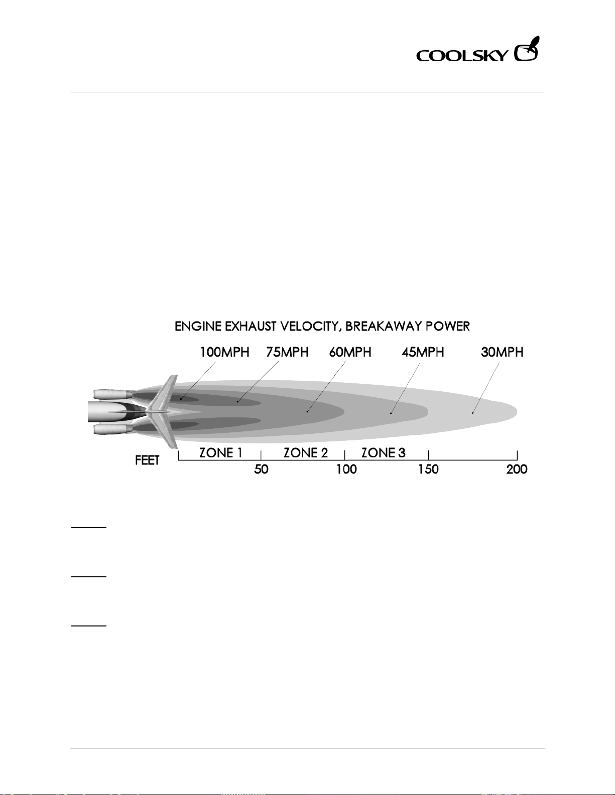
Super 80 Professional – AOM
OPERATING TECHNIQUES
Section 4 Page 3
Super 80 Professional – Aircraft Operating Manual
JET BLAST
When maneuvering on the ramp area special caution must be taken to avoid jet blast damage.
Use the following technique when maneuvering on the ramp area:
• Apply thrust to a maximum of 1.2 EPR.
• Retard both throttles as soon as the aircraft starts rolling.
• If a tight turn is required, leave the power on at 1.2 EPR until the point where jet blast
could cause damage, then close both throttles. This should give the aircraft sufficient
momentum to sustain taxi out of the congested area.
• If 1.2 EPR is not sufficient to move the aircraft out of a gate area where there is danger of
jet blast damage to ground equipment, the Captain should request a tow-out.
Zone 1:
During breakaway power, the jet blast in zone 1 is powerful enough to up-root trees, cause
structural damage to other aircraft, tip over and move heavy objects and break windows.
Zone 2:
During breakaway power, the jet blast in zone 2 is strong enough to weathercock unbraked
aircraft, sway lift trucks, damage roofing and move unsecured objects.
Zone 3:
During breakaway power, the jet blast in zone 3 can move unbraked carts and small objects.
Coolsky, 2018
Page 74

Super 80 Professional – AOM
OPERATING TECHNIQUES
Section 4 Page 4
Super 80 Professional – Aircraft Operating Manual
TAKE-OFF
Before Take-off
Normally, the Before Take-off checklist is
performed while taxiing out to the take-off
position. This checklist must be completed
before commencing the take-off roll.
Runway Alignment
On the runway, line up slightly left or right of
the center line to avoid the centerline lights.
These lights, which are embedded into the
runway surface, can cause nose wheel
thump during the take-off wheel.
When the aircraft is lined up with the
runway, check that the heading indication is
about the same as the runway number.
If a braked take-off is being made, make
sure the nose wheel is aligned with the
runway prior to releasing the brakes.
Rejected Take-off
The braking action provided by the
autobrake system in a rejected take-off
situation is very sudden and abrupt.
Consider using manual braking during a
rejected take-off situation if runway length is
not critical and immediate maximum
braking is not required.
Rotation and Initial Climb
The take-off and initial climb performance
depends on executing the rotation at the
correct speed and proper rate. Rotation at
should be smooth and continuous.
V
R
Rotating late, slow or under rotating causes
the take-off ground run to increase.
Wings level should be maintained all the
way through rotation and initial climb. Lift off
should occur at about 8° deck angle.
Note that with the main gear on the ground,
the tail cone will strike the runway at a body
angle of 10.5°.
General
On the climbout, make shallow turns and
smooth changes in attitude for passenger
comfort.
CLIMB
Leveling Off
When the autopilot is engaged, closely
monitor the FMA to ensure a smooth
transition and level-off. Note that adjusting
the pitch or vertical speed with the pitch
control wheel may disengage the ALT CAP
mode and engage VERT SPD mode.
Coolsky, 2018
Page 75

Super 80 Professional – AOM
OPERATING TECHNIQUES
Section 4 Page 5
Super 80 Professional – Aircraft Operating Manual
CRUISE
Climbing to a Higher Altitude
Start a climb to a higher altitude by using
the VERT SPD mode or by slowly increasing
pitch if hand flying. When the aircraft has
reached the desired climb speed, engage
IAS/MACH HLD.
DESCENT
Descent Speed
Above the Mach crossover altitude,
descend at the cruise Mach speed. Below
the Mach crossover altitude, descend at
280KIAS.
Standard Descent Procedure
The standard procedure for descent is to
descend with a clean aircraft at idle power.
If the pilot needs to expedite the descent for
traffic reasons, speedbrakes should be used
to increase the rate of descent.
Descents with flaps/slats extended and/or
gear down should be avoided as they are
airspeed limited, noisy and expensive.
The FMS will present an optimum descent
profile with Top of Descent (TD) and End of
Descent (ED). ATC and traffic allowing, the
pilot should follow the optimized descent
plan provided by the FMS.
If it becomes necessary to manually
calculate the TD/ED, use the following
method:
Cruise Speed
The cruise speed commanded by the FMS is
the recommended cruise speed. This speed
ensures efficient and economical fuel burn.
• Determine the altitude difference
(total altitude you need to descend)
• 22,000ft
• Drop the last three digits
• 22,000 → 22
• Multiply by three
• 22 x 3 = 66
• For an unrestricted descent to a
landing, add 10 NM.
• 66 + 10 = 76
• For a descent to an intermediate
lower altitude, no additive is
required.
• Add 2 NM for every 10 knots of
tailwind and subtract 2 NM for every
10 knots of headwind.
• 30 knots tailwind
• 76 + (3 x 2) = 82
• Our TD is approximately 82NM away
from our landing destination or ED.
Cabin Pressurization During Descent
A 3° descent profile will help maintain a
300fpm cabin rate of descent. Multiply the
ground speed by six to find the required
vertical speed required to maintain a 3°
descent profile.
Coolsky, 2018
Page 76

Super 80 Professional – AOM
OPERATING TECHNIQUES
Section 4 Page 6
Super 80 Professional – Aircraft Operating Manual
HOLDING
Fuel Economy
When ordered to enter a holding pattern by
ATC, maintain the highest possible altitude
to lower fuel consumption.
If prolonged holding is expected, request
ATC to increase the size of the holding
pattern. This will reduce the number of turns
required. Turns require increased power and
increased fuel burn.
All holding should be flown with a clean
configuration. For best fuel economy, use
the speeds in the holding pattern speed
chart. However, the pilot should always
comply with the ATC minimum holding
speed.
Coolsky, 2018
Page 77

Super 80 Professional – AOM
OPERATING TECHNIQUES
Section 4 Page 7
Super 80 Professional – Aircraft Operating Manual
APPROACH AND LANDING
Visual Approach
Be alert for the following visual illusions when
executing a visual approach:
Runway Slope
An up-sloping runway creates an illusion of
being high on the approach. A downsloping runway creates the illusion of being
low on the approach.
Visibility
Rain, haze, dust, smoke, glare or darkness
may cause the illusion of being too high on
the approach.
Runway Lighting
Strong, bright runway lights appear to be
closer while dim runway lights appear to
be farther away.
Runway Dimensions
The width versus length ratio of the runway
will also affect visual perspective.
Glide Path
The normal approach path is based on a 3°
descent flight path. Once established on the
approach, make small adjustments to the
glideslope, approach speed and trim. The
approach style is essentially the same for
VFR and IFR.
Use the 1000 foot point on the runway as
aim for the approach. This will ensure that
the approach will not be short or
unnecessarily long.
The landing distance is affected by the glide
path as well as the height above the runway
threshold. For example, crossing the
threshold at 100 feet instead of 50 can
increase the landing distance by up to 950
feet on a 3° glide slope. A glide slope of 1°
can increase the landing distance by up to
1500 feet.
Use the ILS or VASI to help you establish the
correct glide path on the approach.
Thrust on Approach
Use the throttles as a primary flight control
on approach. Use the throttles in
coordination with the elevators to control
airspeed, rate of descent and position on
glide path. Always keep one hand on the
throttles, even when using the autothrottle
system.
Note that in the event of a go-around, the
JT8D engines need about 8 seconds to
accelerate from approach idle to goaround power.
Final Approach
A good rule of thumb on final approach to
give a 3° glide path: One-half the ground
speed (knots) times ten will give the required
rate of descent.
For example GS= 100, (100 / 2) x 10 = 500fpm
Another good rule of thumb: For a 3° glide
path maintain 300 feet of altitude for each
mile from the touchdown.
For example: If you are 5 miles from
touchdown, 5 x 300 = 1500 feet. You should
be at 1500 feet altitude when 5 miles from
touchdown.
Coolsky, 2018
Page 78
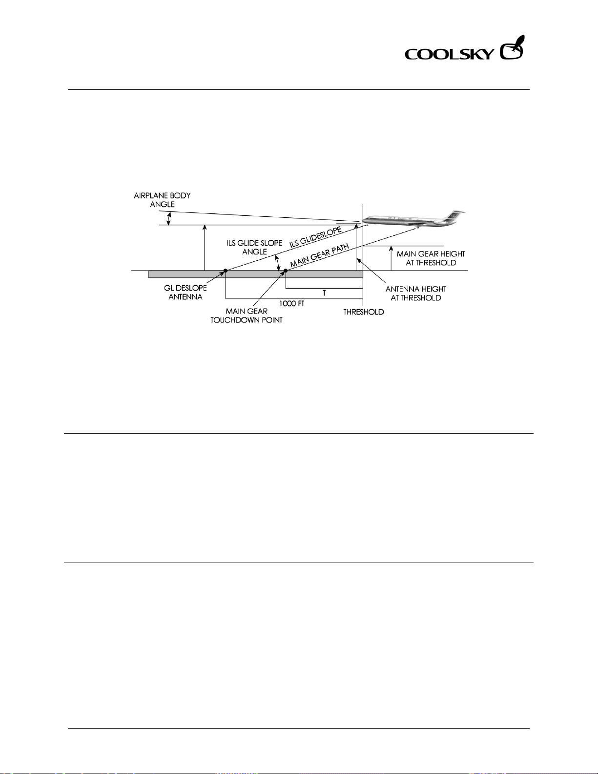
Super 80 Professional – AOM
OPERATING TECHNIQUES
Section 4 Page 8
Glide Path
(Degrees)
Estimated
(Degrees)
Pilot Eye Height
(Feet)
Main Gear Height
(Feet)
Main Gear
T (Feet)
2.5
4.9
44
29
664
2.75
4.65
48
34
708
3.0
4.4
52
39
744
Glide Path
(Degrees)
Estimated
(Degrees)
Pilot Eye Height
(Feet)
Main Gear Height
(Feet)
Main Gear
T (Feet)
2.5
3.2
44
28
649
2.75
2.95
48
33
681
3.0
2.7
52
37
708
Super 80 Professional – Aircraft Operating Manual
Estimated ILS Approach
Estimated touchdown point (no flare) assuming G/S transmitter at 1000 feet.
Flaps 28
Angle
Angle
Body Angle
Body Angle
At Threshold
Flaps 40
At Threshold
At Threshold
At Threshold
Touchdown Point
Touchdown Point
Coolsky, 2018
Page 79
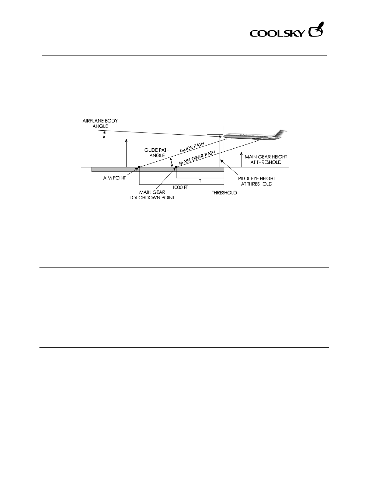
Super 80 Professional – AOM
OPERATING TECHNIQUES
Section 4 Page 9
Glide Path
(Degrees)
Estimated
(Degrees)
Pilot Eye Height
(Feet)
Main Gear Height
(Feet)
Main Gear
T (Feet)
2.5
4.9
44
24
550
2.75
4.65
48
28
583
3.0
4.4
52
32
610
Glide Path
(Degrees)
Estimated
(Degrees)
Pilot Eye Height
(Feet)
Main Gear Height
(Feet)
Main Gear
T (Feet)
2.5
3.2
43
22
503
2.75
2.95
48
27
562
3.0
2.7
52
31
591
Super 80 Professional – Aircraft Operating Manual
Estimated Visual Approach
Estimated touchdown point (no flare) assuming an aim point at 1000 feet.
Flaps 28
Angle
Angle
Body Angle
Body Angle
At Threshold
Flaps 40
At Threshold
At Threshold
At Threshold
Touchdown Point
Touchdown Point
Coolsky, 2018
Page 80

Super 80 Professional – AOM
OPERATING TECHNIQUES
Section 4 Page 10
Super 80 Professional – Aircraft Operating Manual
Touchdown
The descent rate for a normal landing
configuration is about 650 to 850 fpm.
Recommended landing technique is to
reduce the sink rate at approximately 50
feet radio altitude. Smoothly lift the nose 2-3
degrees up to reduce the rate of descent.
Simultaneously, slowly reduce power to idle.
Do not attempt to hold the aircraft off the
runway by further increase in pitch.
Thrust should reach idle power at
touchdown. With proper airspeed and thrust
management, touchdown should occur at
, but never below V
V
REF
The aircraft tends to float in ground effect if
the flare and thrust are excessive. Floating
before touchdown “eats up” a lot of
runway. It is better to put the aircraft down
on the runway if you are coming in to fast,
than trying to bleed the speed off in the air.
The aircraft decelerates three times faster on
the runway than in the air.
It is important to lower the nose on
touchdown and hold a positive forward
pressure on the control column. This
decreases the wing angle of attack,
reduces the lift, and puts more weight on
the main gear. This increases rolling friction,
as well as braking effectiveness. This
procedure is five times more effective than
holding the nose off for aerodynamic
braking.
REF
.
Directional Control
Differential braking may be used to aid in
directional control after touchdown. Nose
wheel steering should not be used until the
aircraft is ready to turn off the runway.
Reverse Thrust
Reverse thrust should be applied
immediately upon touchdown, as reverse
thrust is most efficient at higher airspeeds.
Early application of reverse thrust greatly
reduces runway required for rollout, and
greatly reduces brake temperature and
wear.
The application of reverse thrust tends to
reduce and blank out the effect of the
rudder. At 90 knots and 1.6 EPR, the rudder is
almost completely ineffective.
Immediately reduce reverse thrust to idle
reverse if the aircraft starts drifting across the
runway. This will restore rudder effectiveness
and help regain directional control.
Use of asymmetrical forward thrust to regain
directional control is allowed. Use of
asymmetrical reverse thrust is not allowed.
Speed Brakes
The automatic brake system is inhibited until
the spoilers are deployed (manually or
automatically). Monitor the automatic
deployment of the spoilers at touchdown.
Manually apply the spoilers if they fail to
deploy automatically.
Coolsky, 2018
Page 81

Super 80 Professional – AOM
OPERATING TECHNIQUES
Section 4 Page 11
Super 80 Professional – Aircraft Operating Manual
Autobrakes
The autobrake system senses deceleration
and modulates the brake pressure required
accordingly. Early and effective application
of spoilers and reverse thrust is therefore very
important to minimize brake temperature
and wear.
If only minimum reverse thrust is used, the
brake energy required to stop the aircraft
almost doubles.
Brakes
The brakes slow down the aircraft by
absorbing the motion energy of the aircraft.
The brakes convert this motion energy into
heat, which is dissipated through cooling.
The brakes are required to absorb vast
amounts of energy. The higher the speed is
at the time the brakes are applied, the
higher the amount of energy they have to
absorb.
While reverse thrust is more effective at
higher airspeeds, the brakes are more
effective at lower airspeeds.
During a normal landing, as speed is being
reduced, the brakes should be applied just
prior to the termination of reverse thrust
operation. This practice will result in the most
economical landing performance.
Coolsky, 2018
Page 82

Super 80 Professional – AOM
EMERGENCY PROCEDURES
Section 5 Page 0
Super 80 Professional – Aircraft Operating Manual
SECTION 5
EMERGENCY PROCEDURES
Coolsky, 2018
Page 83

Super 80 Professional – AOM
EMERGENCY PROCEDURES
Section 5 Page 1
Super 80 Professional – Aircraft Operating Manual
Emergency techniques are currently not described.
Coolsky, 2018
Page 84

Super 80 Professional – AOM
AIR CONDITIONING AND PRESSURIZATION
Section 6 Page 0
Super 80 Professional – Aircraft Operating Manual
SECTION 6
AIR CONDITIONING AND
PRESSURIZATION
Coolsky, 2018
Page 85

Super 80 Professional – AOM
AIR CONDITIONING AND PRESSURIZATION
Section 6 Page 1
Super 80 Professional – Aircraft Operating Manual
TABLE OF CONTENTS
SECTION 6: AIR CONDITIONING AND PRESSURIZATION 0
TABLE OF CONTENTS ................................................................................................................. 1
GENERAL .................................................................................................................................... 2
FUNCTIONAL SCHEMATIC - PNEUMATICS .............................................................................. 3
CONTROLS AND INDICATORS ................................................................................................. 4
AIR CONDITIONING .................................................................................................................. 5
PRESSURIZATION ........................................................................................................................ 7
WARNING AND CAUTION INDICATORS ................................................................................. 9
Coolsky, 2018
Page 86

Super 80 Professional – AOM
AIR CONDITIONING AND PRESSURIZATION
Section 6 Page 2
Super 80 Professional – Aircraft Operating Manual
GENERAL
Pneumatics
The pneumatic system provides pressurized
air for cabin pressurization. Air conditioning,
ice protection, engine starting, and potable
water tank pressurization. For ground
operation and engine starting, pneumatic
pressure is supplied by the APU, by ground
power equipment, or by an operating
engine.
In flight pneumatic pressure is supplied by
the low and/or high stage compressors of
both engines. Normally, bleed air from the
left and right engines is supplied to the
respective air conditioning units. Bleed air
from both engines is supplied to the ice
protection systems simultaneously.
Pneumatic crossfeed valves permit
operation of the air conditioning system and
ice protection systems from either engine.
APU bleed air is normally used only for
engine starting and for ground air
conditioning when the engines are not
operating.
Air Conditioning
Pressurized air from the pneumatic system is
used for air conditioning and for pressurizing
the airplane. During ground operation,
pneumatic air to operate the air
conditioning systems can be obtained from
a ground source connected to the airplane,
by the auxiliary power unit (APU), or by the
engines. During flight, only the engines
supply bleed air for operating the air
condition.
The airplane has two identical air
conditioning systems, designed for
independent or parallel operation.
Normally the right system operates from the
right engine bleed air and supplies the
passenger compartment temperature
requirements. The left system operates from
the left engine bleed air and supplies the
flight compartment temperature
requirements.
Pressurization
Pressurization is provided by a controlled
flow of bleed air from the pneumatic supply,
which passes through the air conditioning
systems and is then ducted to the
pressurized areas. Desired pressurization
levels are maintained by regulating escape
of the compressed air through the cabin air
outflow valve. Normally, the outflow valve is
automatically positioned by a dual
automatic pressurization system to control
cabin pressure rates from take-off to
landing.
Dual pressure relief valves are installed to
protect the airplane structure from
maximum input pressure. The relief valves
prevent the cabin differential pressure from
exceeding the maximum limit of 8.32 PSI.
Negative pressure is relieved by the inward
movement of the galley service and
passenger entrance door seals, and one
negative pressure relief valve installed in the
aft pressure bulkhead.
When operating on the pressure schedule,
the cabin rate of climb will be proportional
to the airplane rate of climb, with maximum
limits as set by the rate limit knob. When
climbing or descending toward a selected
altitude above schedule, the cabin rate of
change will be as selected on the rate limit
knob. With the knob at the index mark, the
rate limit is normally 700 fpm climb and 300
fpm descent.
Coolsky, 2018
Page 87
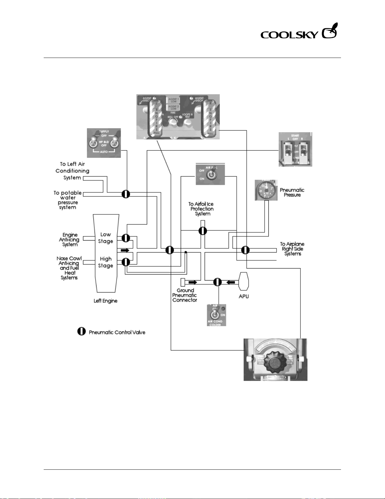
Super 80 Professional – AOM
AIR CONDITIONING AND PRESSURIZATION
Section 6 Page 3
Super 80 Professional – Aircraft Operating Manual
FUNCTIONAL SCHEMATIC - PNEUMATICS
Coolsky, 2018
Page 88
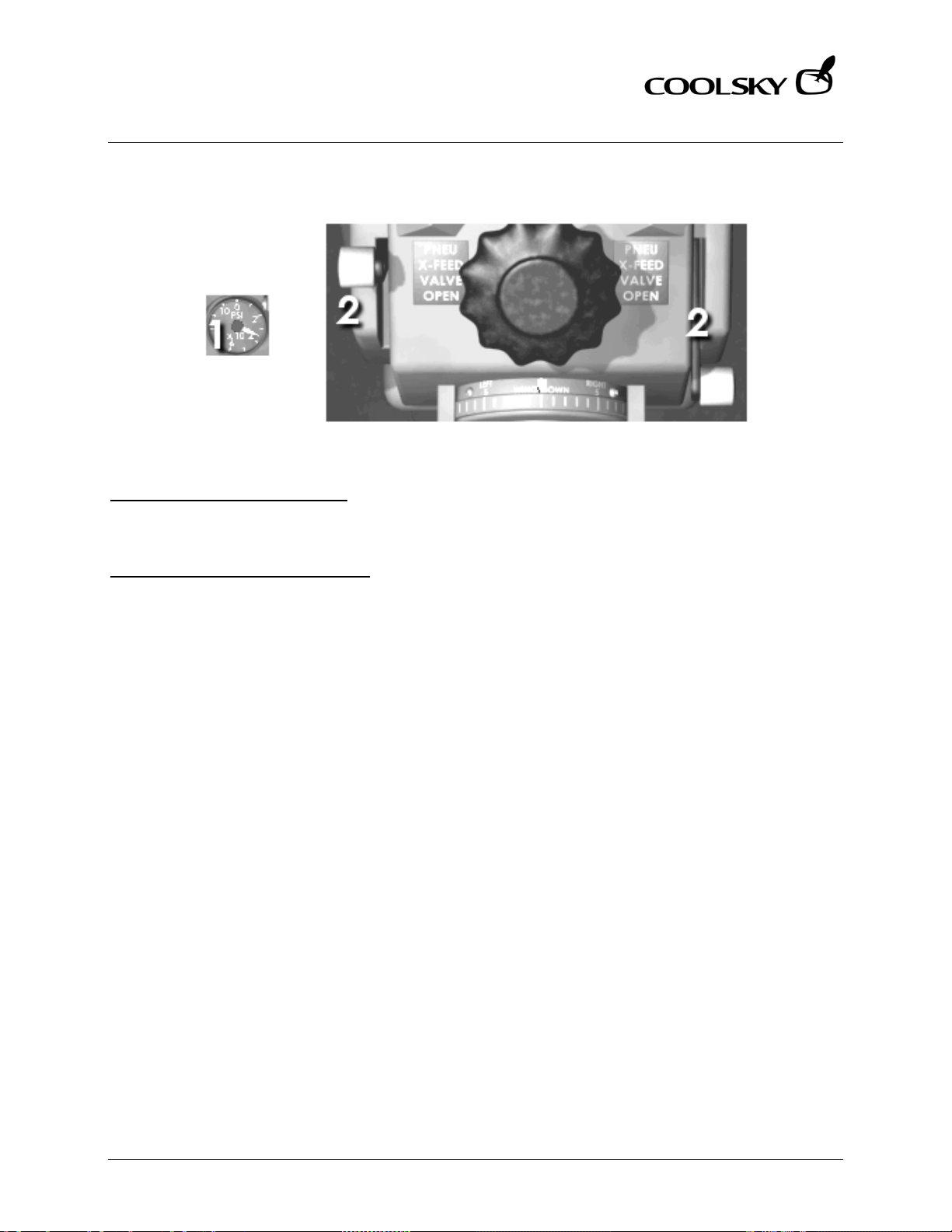
Super 80 Professional – AOM
AIR CONDITIONING AND PRESSURIZATION
Section 6 Page 4
Super 80 Professional – Aircraft Operating Manual
CONTROLS AND INDICATORS
1. PNEUMATIC PRESSURE GAUGE
Indicates pneumatic pressure in the
crossfeed manifold.
2. PNEUMATIC X-FEED VALVE LEVER
Open (Up) Supplies bleed air for air foil
ice protection (in flight only), for
operating both air conditioning
packs from one operating engine,
and for making pneumatic
crossfeed starts from opposite
operating engine. Also, on the
ground, supplies APU bleed air or
air from pneumatic ground source
for operating one or both air
conditioning packs or for engine
starting.
Closed (Down) Shuts off engine bleed air
for air foil ice protection and
pneumatic crossfeed starts, and
each air conditioning pack is
supplied engine bleed air from its
respective engine only. On the
ground, APU bleed air or air from
pneumatic ground source is shutoff
and not available for air
conditioning packs or engine starts.
Coolsky, 2018
Page 89
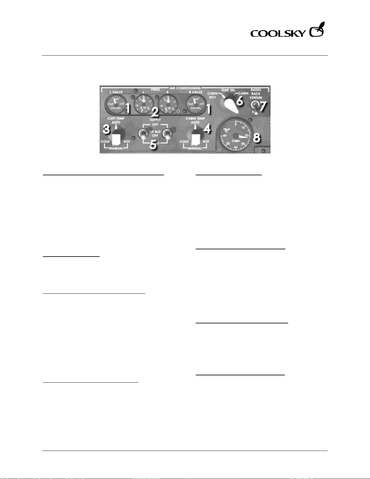
Super 80 Professional – AOM
AIR CONDITIONING AND PRESSURIZATION
Section 6 Page 5
Super 80 Professional – Aircraft Operating Manual
AIR CONDITIONING
1. TEMP CONTROL VALVE INDICATOR (L, R)
Indicates position of air conditioning system
control valve.
COLD Indicates temperature control
valve is closed and blocking hot
air supply.
HOT Indicates temperature control
valve is fully open to allow
maximum hot air supply.
2. PRESSURE GAUGE
Indicates pneumatic supply pressure
available for operation of each air
conditioning pack.
3. COCKPIT TEMPERATURE SELECTOR
AUTO Temperature is automatically
adjusted.
MANUAL COLD (Momentary) Moves
TEMP CONTROL VALVE towards
cold.
MANUAL HOT (Momentary) Moves TEMP
CONTROL VALVE towards hot.
STOP (Momentary) Stops movement of
TEMP CONTROL VALVE in manual
mode.
4. CABIN TEMPERATURE SELECTOR
See Cockpit Temperature Selector.
5. SUPPLY SWITCH (L, R)
OFF Closes off all pneumatic valves
for the air conditioning system.
HP BLD OFF Opens up the regulator valve
but keeps the high press
augmentation valve closed.
AUTO Opens up the regulator valve
and adjusts the augmentation
valve as necessary.
6. TEMPERATURE SELECT SWITCH
CABIN SPLY Selects cabin supply duct
temperature for display on
the Cabin Temperature
Gauge.
CABIN Selects cabin supply duct
temperature for display on
the Cabin Temperature
Gauge.
7. RADIO RACK VENTURI SWITCH
VENTURI Inflight, opens venture valve and
turns off radio rack fan.
FAN Inflight, turns on primary radio
rack fan and closes venture
valve for radio rack cooling.
8. CABIN TEMPERATURE GAUGE
Indicates cabin temperature or cabin supply
duct temperature as selected by Cabin
Temperature Select switch.
Coolsky, 2018
Page 90
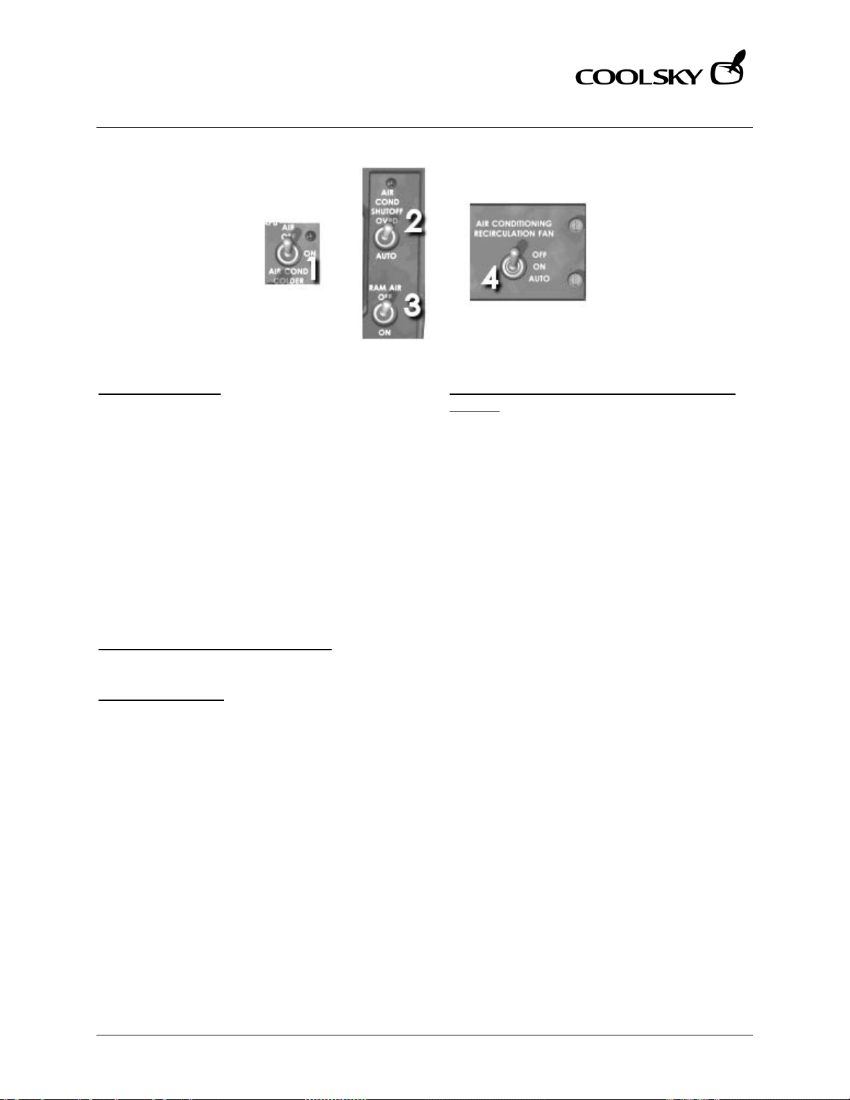
Super 80 Professional – AOM
AIR CONDITIONING AND PRESSURIZATION
Section 6 Page 6
Super 80 Professional – Aircraft Operating Manual
1. APU AIR SWITCH
ON APU bleed control valve opens to
provide APU bleed air to the
airplane pneumatic system.
OFF Closes the APU bleed control
valve.
AIR COND COLDE R Closes turbine bypass
valve and increases differential
pressure across air conditioning
turbine, thus lowering temperature
of conditioned air during ground
operation. Use of this switch
position significantly reduces
airflow in the cockpit and cabin.
2. AIR CONDITION SHUTOFF SWITCH
Not currently simulated.
3. RAM AIR SWITCH
Not currently simulated.
4. AIR CONDITIONING RECIRCULATION FAN
SWITCH
OFF Removes power from recirculation
fan.
ON Allows recirculation fan to operate
on the ground to supplement air
conditioning.
AUTO Recirculation fan operates inflight
only.
Coolsky, 2018
Page 91
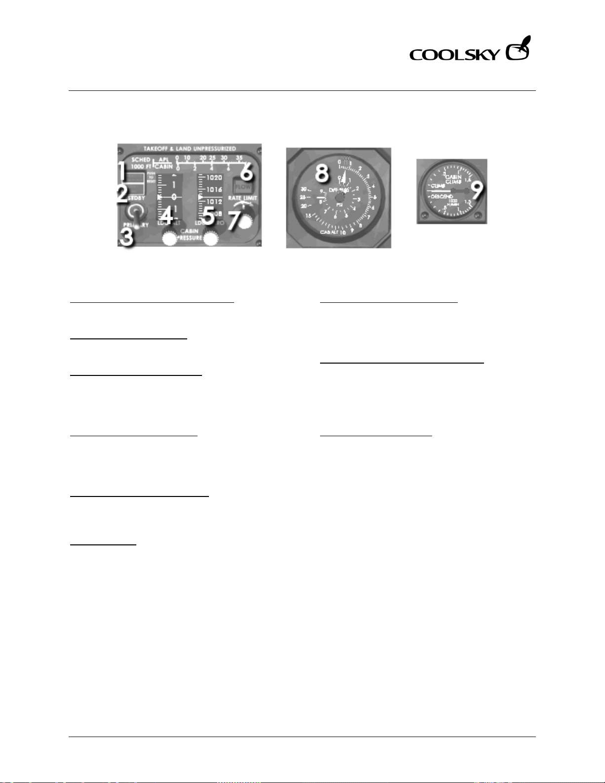
Super 80 Professional – AOM
AIR CONDITIONING AND PRESSURIZATION
Section 6 Page 7
Super 80 Professional – Aircraft Operating Manual
PRESSURIZATION
1. TRANSFER LOCKOUT LIGHT (Blue)
Not currently simulated.
2. STDBY ON LIGHT (Blue)
Not currently simulated.
3. SYSTEM SELECTOR SWITCH
Used to manually transfer system from
primary to standby or return the system from
standby to primary.
4. LDG ALT SELECTOR KNOB
Used to set departure/destination airport
altitude in the landing altitude window. The
scale is numbered in 100 ft increments.
5. LDG BARO SELECTOR KNOB
Used to set departure/destination
barometric pressure in Mb/In Hg window.
6. FLOW LIGHT
Indicates current air flow is insufficient
maintain cabin pressure. The cause may be
insufficient air conditioning inflow or
excessive fuselage leakage. Press to test
light.
7. RATE LIMIT CONTROL KNOB
Normally set at index mark and does not
require adjustment unless a rapid climb or
descent is anticipated.
8. CAB ALT AND DIFF PRESS GAUGE
Outer CAB ALT dial indicates existing cabin
altitude in thousands of feet. Inner DIFF PRESS
dial shows difference in pressure between
cabin and ambient in PSI.
9. CABIN CLIMB GAUGE
Standard rate instrument, indicates rate of
change in feet per minute in cabin altitude
during automatic or manual control.
Coolsky, 2018
Page 92
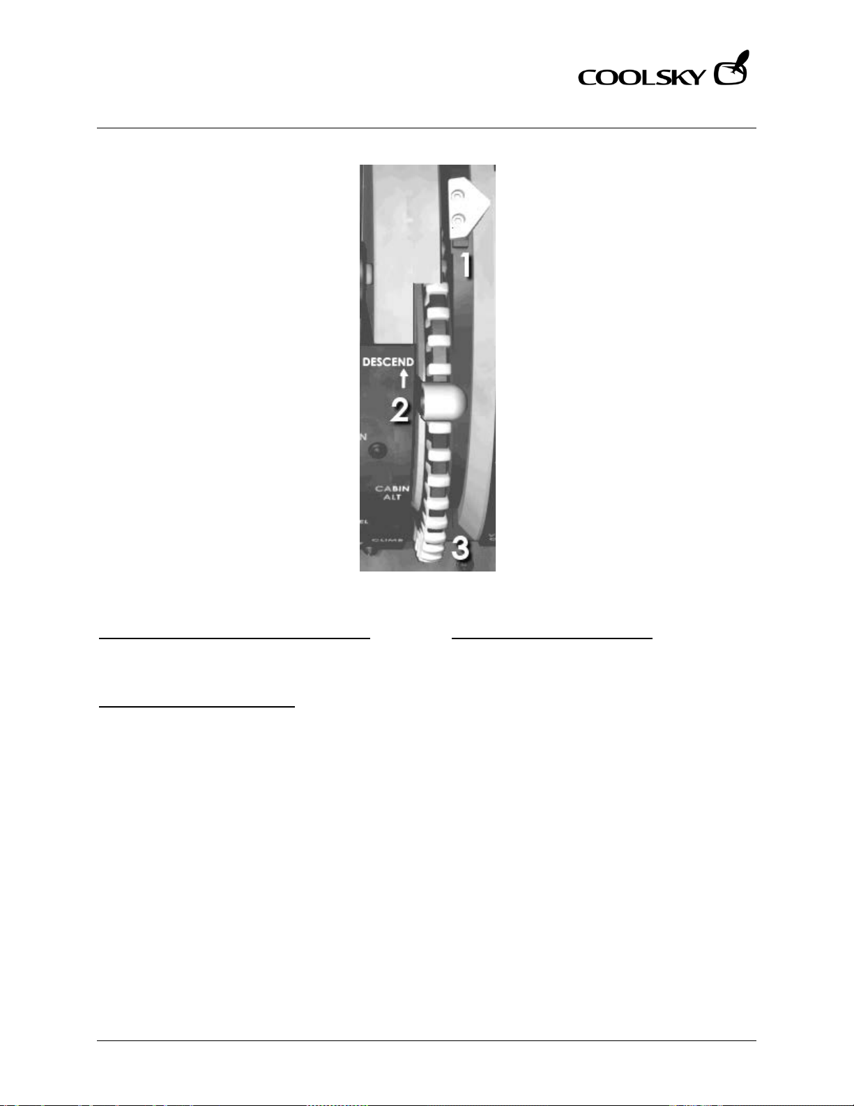
Super 80 Professional – AOM
AIR CONDITIONING AND PRESSURIZATION
Section 6 Page 8
Super 80 Professional – Aircraft Operating Manual
1. OUTFLOW VALVE POSITION INDICATOR
Indicates position of cabin air outflow valve.
Fully forward – open, fully aft – closed.
2. CABIN ALT CONTROL LEVER
Auto (Up) Ca b i n altitude is controlled
automatically.
Manual (Down) Cabin altitude is
manually controlled by adjusting
the Cabin Altitude Control
Wheel.
3. CABIN ALT CONTROL WHEEL
With Cabin Altitude Control lever in auto
(up) position, the control wheel rotates as
cabin air outflow valve automatically adjusts
to maintain cabin altitude.
With Cabin Altitude Control lever in manual
(down) position, rotate the control wheel in
the desired direction to adjust cabin air
outflow valve.
Coolsky, 2018
Page 93
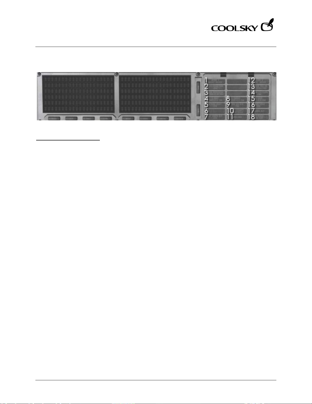
Super 80 Professional – AOM
AIR CONDITIONING AND PRESSURIZATION
Section 6 Page 9
Super 80 Professional – Aircraft Operating Manual
WARNING AND CAUTION INDICATORS
10. CABIN ALT LIGHT (Red)
Comes on when cabin altitude exceeds
10,000 ft. The CABIN ALT light is
accompanied by the MASTER WARNING
light. The NO SMOKING and FASTEN SEAT
BELTS signs in the cabin also come on.
Coolsky, 2018
Page 94

Super 80 Professional – AOM
ANTI-ICE AND RAIN PROT ECTION
Section 7 Page 0
Super 80 Professional – Aircraft Operating Manual
SECTION 7
ANTI-ICE AND RAIN
PROTECTION
Coolsky, 2018
Page 95

Super 80 Professional – AOM
ANTI-ICE AND RAIN PROT ECTION
Section 7 Page 1
Super 80 Professional – Aircraft Operating Manual
TABLE OF CONTENTS
SECTION 7: ANTI-ICE AND RAIN PROT ECTION 0
TABLE OF CONTENTS ................................................................................................................. 1
GENERAL .................................................................................................................................... 2
CONTROLS AND INDICATORS ................................................................................................. 3
WARNING AND CAUTION IND .................................................................................................. 5
Coolsky, 2018
Page 96

Super 80 Professional – AOM
ANTI-ICE AND RAIN PROT ECTION
Section 7 Page 2
Super 80 Professional – Aircraft Operating Manual
GENERAL
General
The airplane ice protection systems employ
hot air and electrical heating for anti-icing
and anti-fogging functions. Rain removal is
accomplished by chemical repellent and
electrically operated windshield wipers.
Window Heat
Electrical heating provides heat for anti-icing
and anti-fogging of the pilot’s three
windshields, and anti-fogging for the
clearview and overhead windows.
Probe Heat
Electrical heating is used for anti-icing the
pitot tubes, static port areas, stall angle of
attack vanes, and ram air temperature
probe.
Airfoil Ice Protection
The airfoil ice protection system provides
anti-icing heat to the wing leading edge
slats, forward strakes, and to the air
conditioning ram air-scoop inlet in flight,
when the air foil switch and associated
pneumatic crossfeed valves are actuated.
De-icing is available for the horizontal
stabilizer leading edge by the tail de-ice
pushbutton. Heat is then diverted from the
wing leading edge slats and strakes to the
horizontal stabilizer. Tail de-icing is provided
for 2.5 minutes, and then flow is reverted
back to the wing slats and strakes again.
When air foil anti-icing is selected, tail deicing will automatically be selected every 15
minutes.
Forward strakes anti-icing is accomplished
through the same system as the wing
leading edge slats, and is controlled by the
same switch.
Clear Ice Detectors
Triangular decals, with a piece of parachute
cord attached, are installed on the upper
inboard surface of both wings. The purpose
of these decals is to assist the de-icing crew
during de-icing. If clear ice is present the
cords will remain frozen to the wing. De-icing
fluid should be applied until the cords move
freely. The triangles provide a secondary
visual reference as the edges of the triangle
will appear irregular if covered with clear
ice.
Engine Anti-Ice
Engine anti-icing is provided by
independent system, controlled by
individual switches located on the overhead
ice protection panel. Each engine provides
ice protection for the respective engine,
nose cowl, inlet bullet, and compressor inlet
guide vanes.
Coolsky, 2018
Page 97
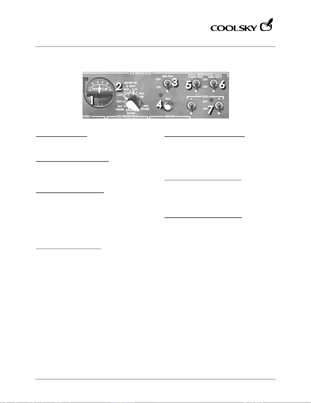
Super 80 Professional – AOM
ANTI-ICE AND RAIN PROT ECTION
Section 7 Page 3
Super 80 Professional – Aircraft Operating Manual
CONTROLS AND INDICATORS
1. HEATER CUR METER
Displays current flow to each position as
selected by the METER SEL & HEAT switch.
2. METER SEL & HEAT SELECTOR
When the selector is moved from the OFF
position, all pitot tubes, rudder limiter, stall
probes and static ports are heated.
3. AIR FOIL ANTI-ICE SWITCH
OFF Stops the flow of heated air to the
wing leading edge slats, strakes, and
horizontal stabilizer.
ON Opens up the pressure regulator
valve to allow heated air to flow to
the wing leading edge slats, strakes,
and horizontal stabilizer.
4. TAIL DE-ICE PUSHBUTTON
Closes shutoff valve to the wings and strakes,
and opens up the shutoff valve to de-ice the
tail. After a timed period, 2.5 minutes, the
system automatically reverts back to antiicing the wings and strakes.
5. WINDSHIELD ANTI-FOG SWITCH
OFF Deactivates the anti-fog system.
ON Prevents and/or removes
condensation on the inside surface
of the windshields, clearview, and
overhead windows.
6. WINDSHIELD ANTI-ICE SWITCH
OFF Deactivates the window anti-ice
system.
ON Provides anti-ice heat to three
windshields.
7. ENG ANTI-ICE SWITCHES (L, R)
OFF Closes valves to shut off air to engine
anti-ice system.
ON Opens valves to provide heater air to
anti-ice engine nose cowl, bullet,
and inlet compressor guide vanes.
Coolsky, 2018
Page 98
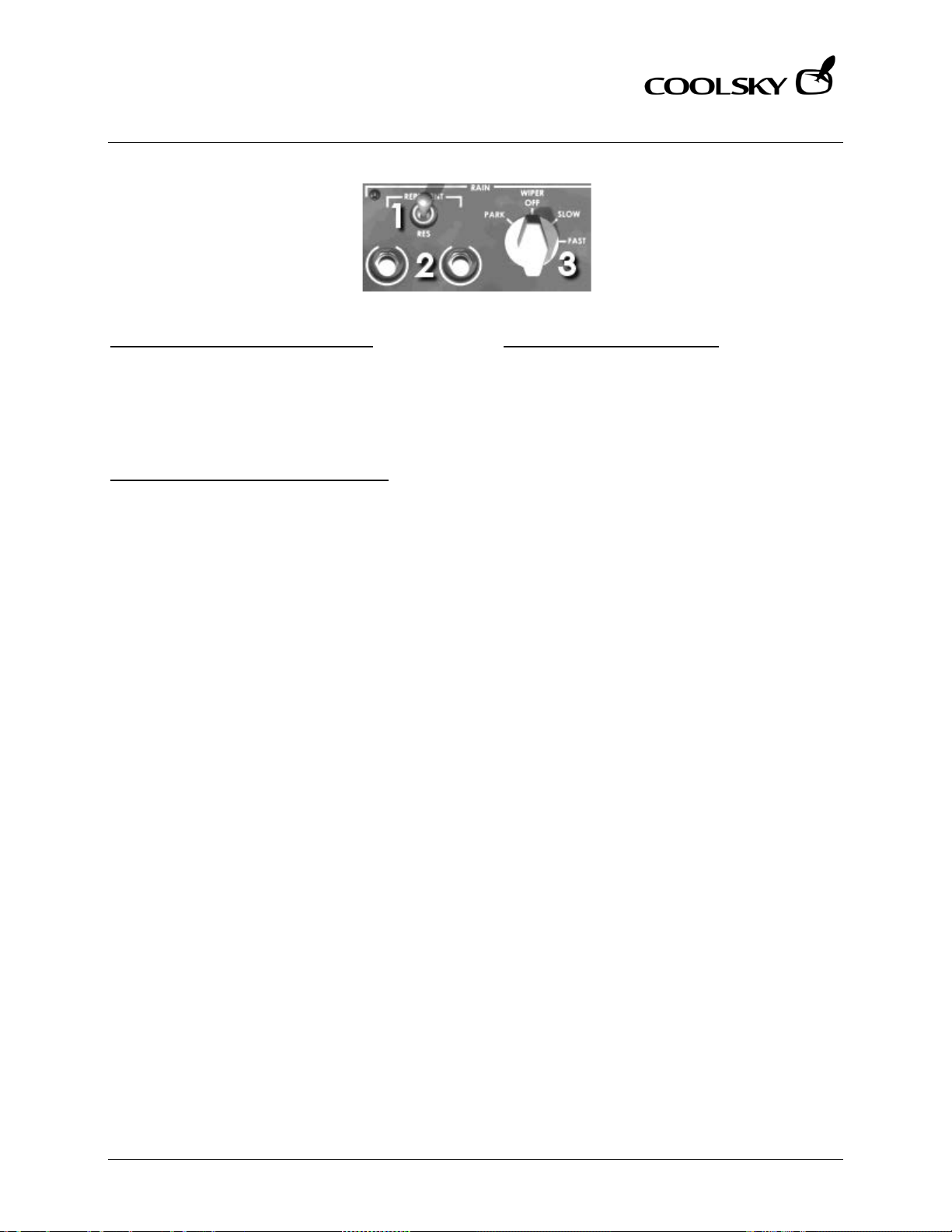
Super 80 Professional – AOM
ANTI-ICE AND RAIN PROT ECTION
Section 7 Page 4
Super 80 Professional – Aircraft Operating Manual
1. RAIL REPELLENT SELECTOR SWITCH
RES (Momentary) Positions selector valve
from primary to reserve fluid
container. Selector valve cannot be
reset to primary until serviced by
maintenance.
2. RAIN REPELLENT PUSHBUTTONS (L, R)
Discharges a metered quantity of fluid from
spray nozzles onto the windshield.
3. WINDSHIELD WIPER SWITCH
Controls variable speed, electrically
operated windshield wipers. Wipers should
be used in conjunction with rain repellent.
Coolsky, 2018
Page 99
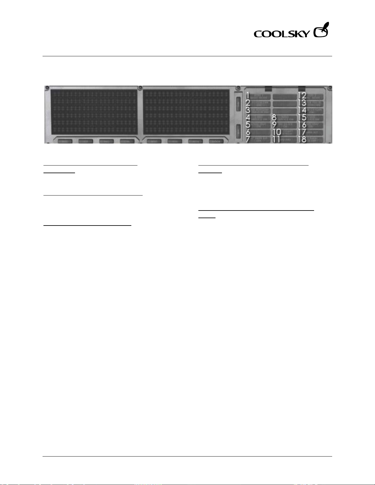
Super 80 Professional – AOM
ANTI-ICE AND RAIN PROT ECTION
Section 7 Page 5
Super 80 Professional – Aircraft Operating Manual
WARNING AND CAUTION INDICATORS
4 & 15. ENG ANTI-ICE ON LIGHTS
(L, R)(Blue)
Indicates engine anti-ice system is on.
8. WING ANTI-ICE ON LIGHT (Blue)
Indicates anti-ice heat has been selected
for wing leading edge and strakes.
9. TAIL DE-ICE ON LIGHT (Blue)
Indicates de-ice heat has been selected for
the leading edge of the horizontal stabilizer.
PITOT/STALL HEATER OFF LIGHT (Digital
display)
Comes on to indicate METER SEL & HEATER
selector in OFF. MASTER CAUTION light also
comes on.
3. RAIN REPELLENT RESERVE IN USE LIGHT
(Blue)
Indicates reserve fluid container has been
selected.
Coolsky, 2018
Page 100

Super 80 Professional – AOM
AUTO-FLIGHT
Section 8 Page 0
Super 80 Professional – Aircraft Operating Manual
SECTION 8
AUTO-FLIGHT
Coolsky, 2018
 Loading...