

Cool Air LBW-420-LEL User Manual
Models
LBW-420-LEL (24 VDC powered)
Ammonia Leak Detector

P a g e | 1
Rev. 2.1 7-7-2017
Copyright © 2017 by Cool Air Incorporated. All rights reserved.
CAUTION & SYMBOL DEFINITIONS:
CAUTION: Gives detailed description of different
situations to avoid or not avoid for the proper operation of the
equipment.
WARNING: RISK OF ELECTRIC SHOCK. DO NOT
REMOVE COVER. NO USER SERVICEABLE
PARTS INSIDE. REFER TO QUALIFIED SERVICE
PERSONNEL.
AVIS: RISQUE DE CHOC ELECTRIQUE. NE PAS
ENLEVER LE COUVERCLE. AUCUN ENTRETIEN
DE PIECES INTERIEURES PAR L'USAGER.
CONFIER L'ENTRETIEN AU PERSONNEL
QUALIFIE.
AUTHORIZED DISTRIBUTOR:
GasDetectorsUSA.com
Houston, Texas USA
sales@GasDetectorsUSA.com
832-615-3588

P a g e | 2
Rev. 2.1 7-7-2017
Copyright © 2017 by Cool Air Incorporated. All rights reserved.
TABLE OF CONTENTS
IMPORTANT—READ THIS FIRST ................................................................... 3
CAUTIONS ............................................................................................................. 3
AVOIDING NUISANCE ALARMS ............................................................................. 3
INTRODUCTION .................................................................................................... 4
STANDARD FEATURES ...................................................................................... 4
AVAILABLE OPTIONS ....................................................................................... 5
PARTS DESCRIPTION ........................................................................................ 6
FRONT PANEL DISPLAY ........................................................................................ 6
AMMONIA SENSOR ............................................................................................... 7
FRONT PANEL-MOUNTED CIRCUIT BOARD ......................................................... 7
SERVICE JUMPER (SERVICE MODE) ..................................................................... 8
THE “ENTER”, “UP”, AND “DOWN” PUSHBUTTONS ....................................... 8
ROTARY SELECTOR SWITCH ................................................................................ 8
ENCLOSURE-MOUNTED CIRCUIT BOARD ........................................................... 10
POWER CONNECTIONS ................................................................................. 10
J3 SETTINGS ..................................................................................................... 10
RELAYS ............................................................................................................... 11
RELAY STATUS LEDS ......................................................................................... 12
EXTERNAL CONNECTIONS .................................................................................. 12
4–20 mA Analog Output ............................................................................ 12
4 to 20mA WIRING………………………………13
Wiring Diagram: LBW-420-LEL 3 wire – 24 VDC Power Supply…….13
Wiring Diagram: LBW-420-LEL 4 wire – 24 VDC Power Supply…….14
INSTALLATION AND SETUP .......................................................................... 15
REMOTE ALARM LIGHT AND HORN UNIT ............................................ 17
PROGRAMMING AND OPERATION ............................................................. 18
PROGRAMMING THE AMMONIA ALARM SET POINTS ......................................... 18
RESETTING THE RELAYS .................................................................................... 18
PROGRAMMING THE 4 TO 20MA RANGE ............................................................ 19
SETTING THE SERVICE MODE TIMEOUT ............................................................ 19
TEST AND CALIBRATION ............................................................................... 20
TESTING THE DETECTOR .................................................................................... 20
CALIBRATING THE DETECTOR ........................................................................... 21
TECHNICAL SUPPORT .................................................................................... 22
WARRANTY ........................................................................................................ 23
LBW-420 SPECIFICATIONS
............................................................................. 26

P a g e | 3
Rev. 2.1 7-7-2017
Copyright © 2017 by Cool Air Incorporated. All rights reserved.
IMPORTANT—READ THIS FIRST
PLEASE READ AND UNDERSTAND THIS SECTION
BEFORE INSTALLING AND OPERATING THE LBW-
420-LEL DETECTOR
CAUTION:
After applying power, test the detector to ensure it is operating
correctly. Be sure the detector has been powered for at least 10
minutes before testing.
Do not store this manual inside the detector, as this
might result in damage to components from excessive
heat.
ADEQUATELY COVER THE DETECTOR SENSOR
DURING WASHDOWN, AND AVOID SPRAYING THE
WASHDOWN LIQUID DIRECTLY ONTO THE SENSOR
Avoiding unwanted Alarms or shutdowns
To avoid nuisance alarms, place the detector in service mode
before:
Programming the alarm set point.
Performing maintenance, repairs, testing, or calibration.
Performing refrigeration system maintenance.
Removing the ammonia sensor.

P a g e | 4
Rev. 2.1 7-7-2017
Copyright © 2017 by Cool Air Incorporated. All rights reserved.
INTRODUCTION
The Cool Air Incorporated LBW-420-LEL Detector is a state-ofthe-art ammonia leak detector that detects and displays ammonia
concentrations of 0 to 9.9%. It comes equipped with a long-life
ammonia sensor that has a quick and accurate response to ammonia
concentrations.
The Cool Air Incorporated LBW-420-LEL has a fully isolated DC
to DC power supply, allowing the LBW-420-LEL to be powered
from the same DC supply as the 4-20 mA monitoring circuits
without concern for ground isolation.
The LBW-420-LEL requires a DC supply voltage between 18 and
36 volts DC.
The LBW-420-LEL can be configured to supply power to the 4-20
mA circuit(s) or can operate as a fully isolated 4-20 mA sensor.
Refer to 4–20 mA Analog Outputs for more details.
The Cool Air Incorporated LBW-420-LEL can be optionally
equipped with an AC to DC converter to allow operating the
detector with 100 to 240VAC input.
Once the detector senses ammonia at or above the ALARM set
point, the relays will activate and stay activated until a relay rest is
initiated (see “Resetting the Relays”)
STANDARD FEATURES
All LBW-420-LEL’s come with these additional standard features:
Programmable Alarm set point.
Selectable Service Mode timeout.
Range selectable 4-20 mA analog output signals, for
ammonia
Normally-open, normally-closed contacts for shutting
down compressors and closing valves.
A NEMA 4X, UL-listed enclosure.
P a g e | 5
Rev. 2.1 7-7-2017
Copyright © 2017 by Cool Air Incorporated. All rights reserved.
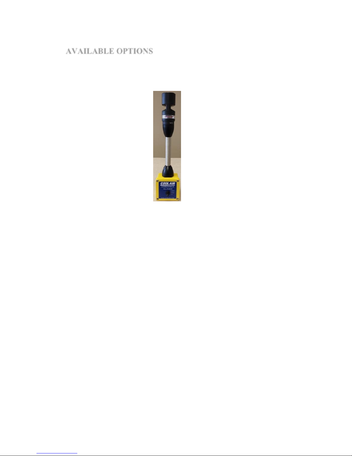
AVAILABLE OPTIONS
A remote alarm light and horn box with a toggle switch to
TEST/NORMAL/SILENCE the alarm.
Contact Cool Air Incorporated technical support for more detailed
information, or for purchasing any of these options.

P a g e | 6
Rev. 2.1 7-7-2017
Copyright © 2017 by Cool Air Incorporated. All rights reserved.
PARTS DESCRIPTION
Front Panel Display
The front panel display is comprised of a digital display and a series
of labeled indicating LED’s. The seven-segment, four-digit display
indicates a variety of information, such as ammonia concentration
and more, depending on the position of the rotary selector switch.
Ammonia concentration is displayed in percent ammonia. The
LED’s provide an indication of ammonia concentration and alarm
status at a glance.
Alarm indication
All Relays will be
active when this is on.
Alarm disabled
indication. All relays
will be deactivated when
this LED is on.
Two digit seven segment display.
In normal operating mode this
will display the ammonia
concentration. It will also be use
in setting options and calibration.

P a g e | 7
Rev. 2.1 7-7-2017
Copyright © 2017 by Cool Air Incorporated. All rights reserved.
Ammonia Sensor
The detector comes with a long-life sensor that has a high
sensitivity to ammonia with a quick response at levels above .1%.
Front Panel-Mounted Circuit Board
The front panel-mounted circuit board contains the controls
necessary for programming and operating the detector. Each
control is described in detail below. When the detector enclosure is
open, this circuit board is on the left, attached to the front panel.
NOTE: The service switch may be a jumper instead of the switch.

P a g e | 8
Rev. 2.1 7-7-2017
Copyright © 2017 by Cool Air Incorporated. All rights reserved.
Service Jumper (Service Mode)
The detector can be set to one of two modes: normal operating
mode or service mode. The detector is in normal operating mode
when the service jumper is in the “OFF” position. When the service
jumper is in the “ON” position, the detector continues to function as
usual, however the alarm, pre-alarm, and auxiliary relays are
disabled as well as the 4 to 20mA signal is set to 4ma (0%). This
allows the detector to be serviced, tested, and calibrated without
tripping the alarm relays and setting alarms or causing shutdowns.
When the detector is in the service mode, “Alarms Disabled” LED
will be illuminated (service jumper “on”). This is done as a
reminder to set the jumper back to “off” when service is done. If
the service jumper is not returned to off it will automatically return
to an as off state after a selected amount of time. The factory default
is 15 minutes.
See “Setting the Service Mode Timeout”
The “ENTER”, “UP”, and “DOWN” Pushbuttons
The “UP” and “DOWN” buttons are used for setting the digital
display to the desired value, and the “ENTER” button is used for
programming a value previously set on the digital display. These
buttons are used when programming: the set points, configuring
other options, they are also used during calibration of the detector.
Rotary Selector Switch
The rotary selector switch (labeled “MENU SELECT” on the front
panel-mounted circuit board) is used for performing functions such
as:
Setting the information displayed on the front panel
Programming set point
Displaying system information
Calibrating the detector
Resetting the relays
When the detector is in operation, this switch is typically set to
position “0” to continuously display ammonia concentration.
 Loading...