

Coolair FGBCB52, FGBC36 User Manual
FARM PRODUCTS DIVISION
AMERICAN COOLAIR CORPORATION
PHONE (904) 389-3646 FAX (904) 387-3449
MEMBER OF AMCA
P.O. BOX 2300
JACKSONVILLE, FLORIDA 32203
E-MAIL - fans@coolair.com
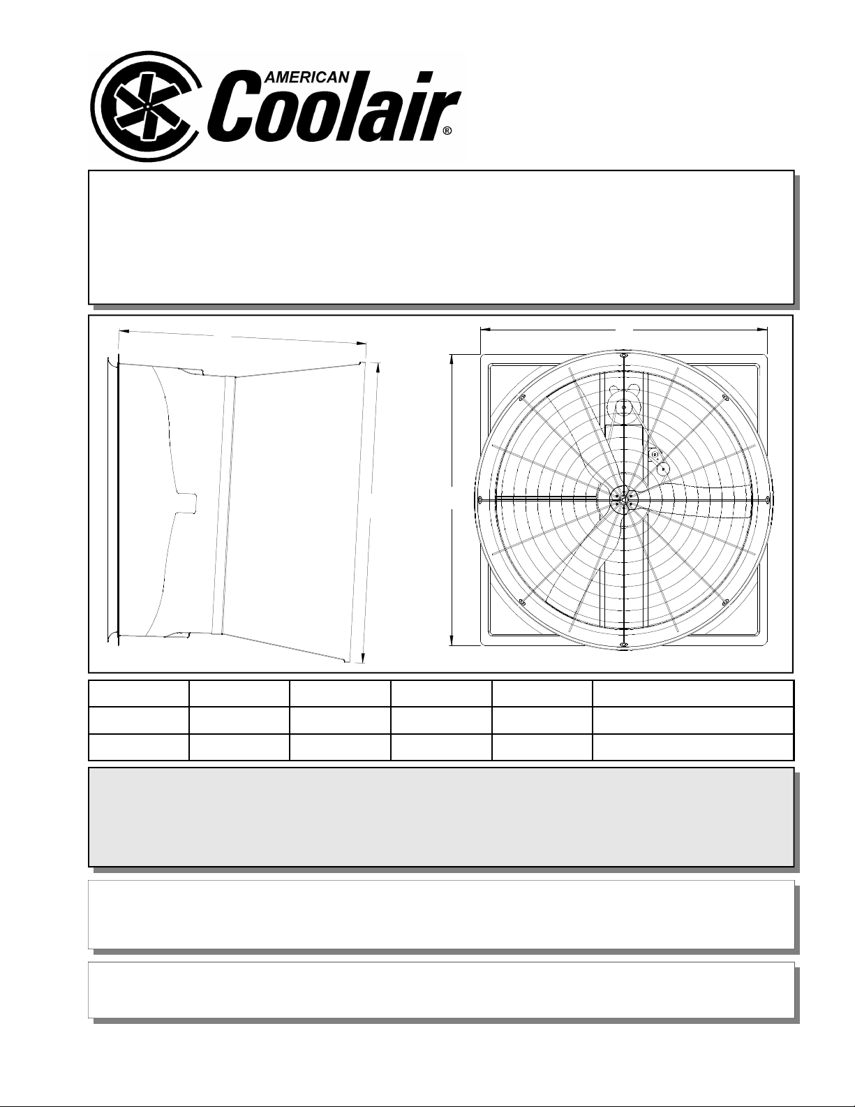
FGBC36 and FGBCB52
Figure 1
FIBERGLASS FANS
D
C
B
A
FAN SIZE A B C D FRAMED ROUGH OPENING
36 44 1/2 44 3/4 48 1/8 46 41 1/2 X 41 1/2
52 59 3/4 60 3/8 51 5/8 62 1/2 56 7/8 X 56 7/8
FGBC36J
and
FGBCB52K * FGBCBE52L * FGBCB52L * FGBCB52M
UNPACKING
Inspect the fan for signs of shipping damage. It is the responsibility of the customer to report any
shipping damage to the freight carrier.
WHAT SHOULD YOU FIND?
Fan, Shutter, Cone, Guard and Hardware Package
PAGE 1 OF 14
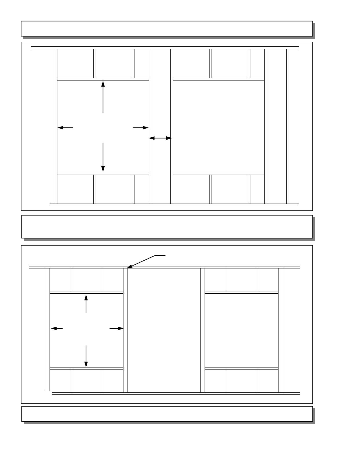
FRAMING INSTRUCTIONS
36 SIZE FANS
41” SQ. I.D.
52 SIZE FANS
56 7/8” SQ. I.D.
Spacing
Figure 2
FRAME CONSTRUCTION
RECOMMENDED SPACING IS 12”
4” x 4” Post
36 SIZE FANS
41” SQ. I.D.
52 SIZE FANS
56 7/8” SQ. I.D.
Figure 3
PAGE 2 OF 14
POST CONSTRUCTION
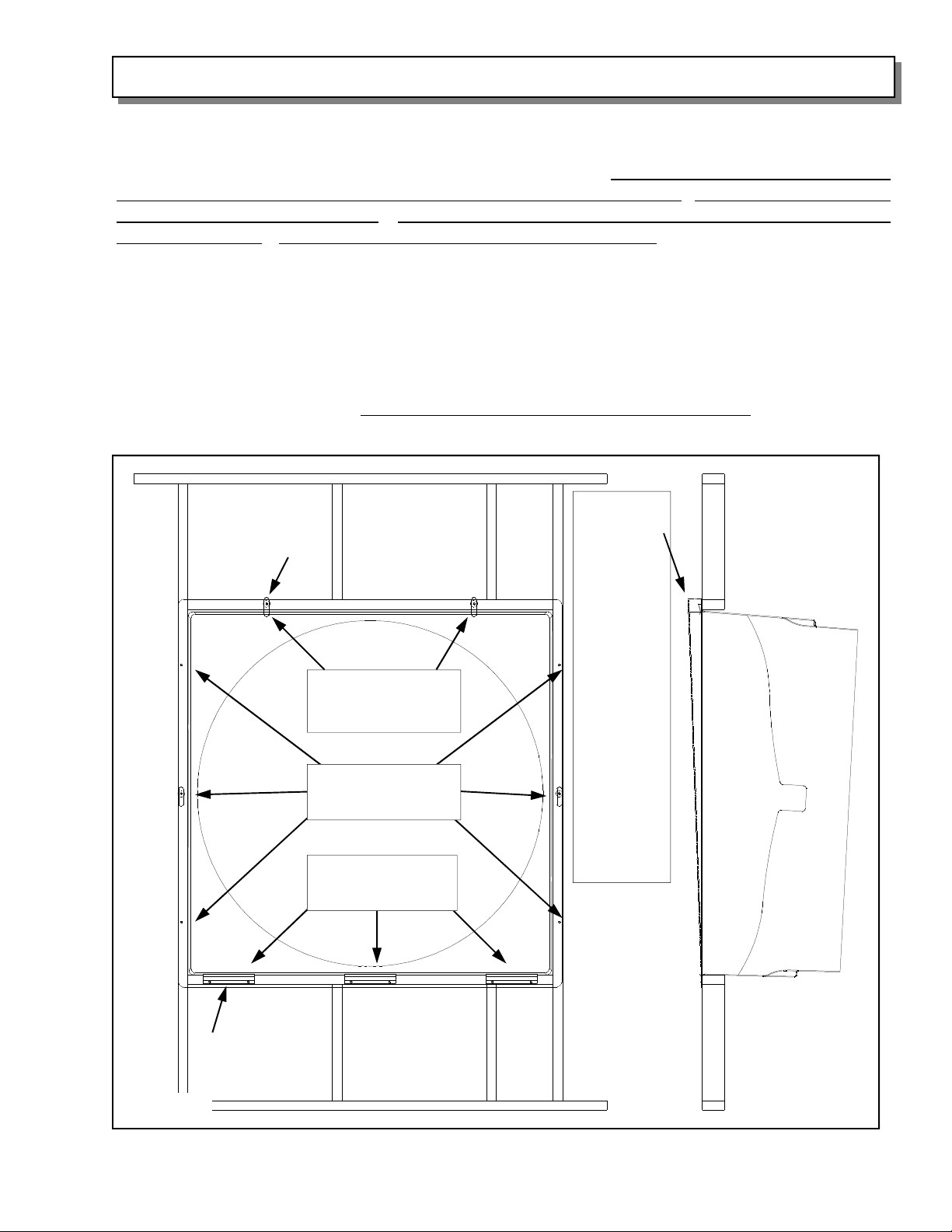
FAN HOUSING INSTALLATION INSTRUCTIONS
Insert the fan housing assembly through the framed opening of the wall from the inside, and
secure it to the wall using four (4) of the 1/4” x 1 1/2” long rubber grommet lag screws through
the pre-drilled holes in the side flanges of the fan housing. Check installation by eye and see
if back of fan housing is planar and not twisted in the wall opening. The fan housing MUST
NOT be installed out of square. Doing so will result in an out of round condition and blade
rubbing will occur. If necessary, shim the housing so it is square. See Figure 4. Next, there
are three (3) shutter mounting clips that are attached to the fan using six (6) of the 1/4” x
1 1/2” long rubber grommet lag screws through the pre-drilled holes in the bottom flange of
the fan housing and into the framed opening. Finally, there are four (4) shutter latches and
four (4) 7/8” O.D. rubber washers that are attached to the fan using four (4) of the 1/4” x 1 1/2”
long rubber grommet lag screws. The rubber washer goes between the housing and the
shutter latch. Place the shutter in the shutter mounting clips and match, mark and drill the
four (4) 1/4” holes through the fan housing so shutter latch can rotate 90 degrees out of the
way to remove the shutter. If necessary, shim the housing so it is square. Install flashing
around fan and caulk to properly seal fan to wall.
Check by eye
to see that
back of fan is
Shutter Latch
Two (2) 1/4” x 1 1/2”
long rubber grommet
lag screws
Six (6) 1/4” x 1 1/2”
long rubber grommet
lag screws
Six (6) 1/4” x 1 1/2”
long rubber grommet
lag screws
planar and
not twisted. If
you sight
across the
back of the fan
housing, the
two vertical
flanges should
be parallel. If
you see that
they are not
(shown by
dotted lines as
if they were
the opposite
side fan housing flange),
this condition
will cause
blade rubbing.
Shim to correct if necessary.
Shutter
Mounting Angle
Figure 4
Note: Fan components have been removed for clarity of details.
PAGE 3 OF 14
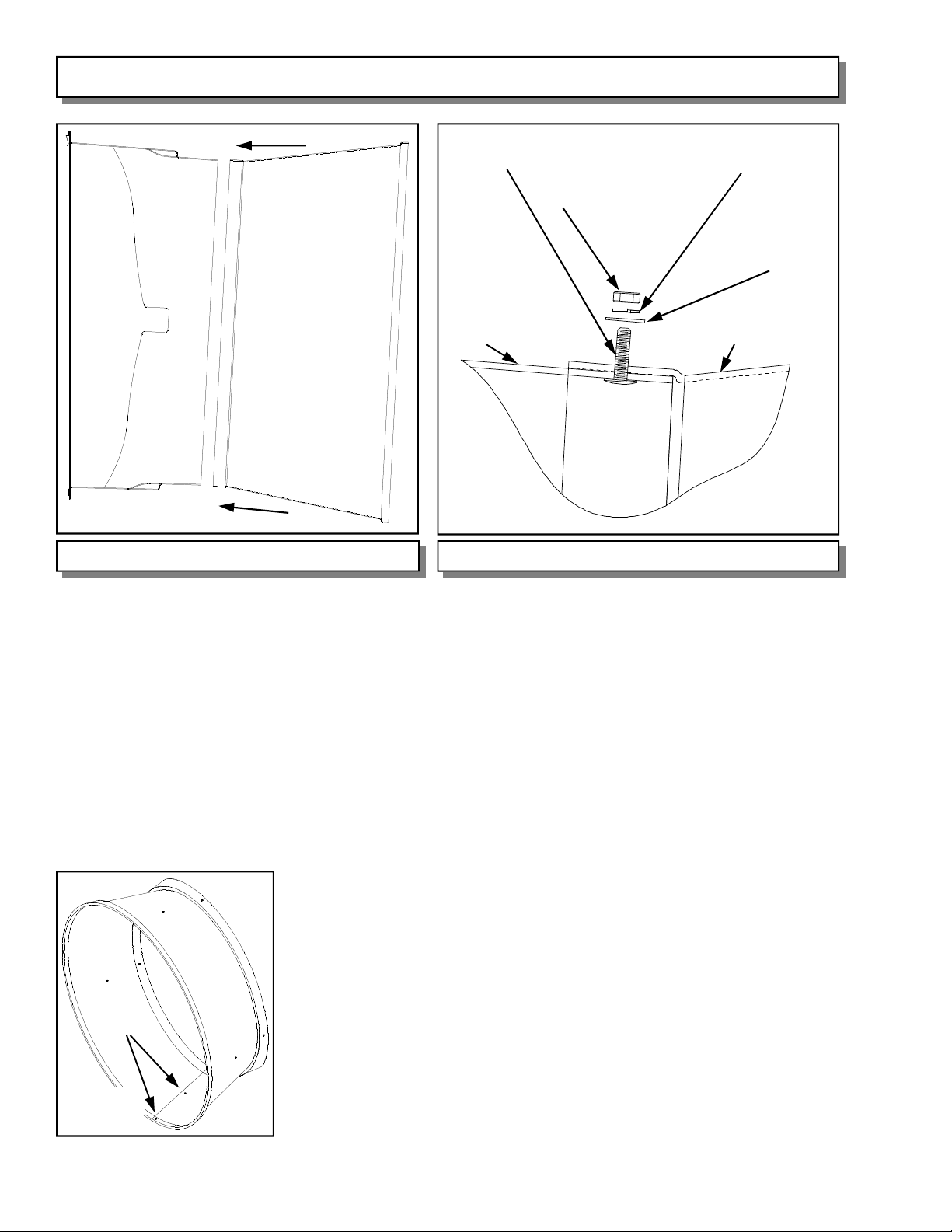
ONE PIECE CONE INSTALLATION INSTRUCTIONS
1/4” x 1” wafer head
Phillips screw
CONE SLIPS
OVER END
OF FAN
Figure 5 Figure 6
Fan housing Cone
1/4” hex nut
1/4” lock washer
1/4” flat washer
Side View of Fan Housing and Cone Detailed View of Hardware for Cone to Fan Housing
If you are installing 52” fans, skip this and refer to page 5, and follow
“
FOUR PIECE CONE INSTALLATION INSTRUCTIONS”
The one piece cone is tapered at the inlet end so it will fit snugly over the fan housing. Fasten
the cone at the overlap with two (2) 1/4” x 1” hex head bolts, flat washers, lock washer and
nut, only finger tight for now. See Figure 5A. Rotate cone while pushing it against the fan to
line up the pre-drilled holes, and it will slide over the fan. See Figure 5. Fasten the cone to
the fan housing with four (4) 1/4” x 1” wafer head Phillips screws, pushing the screws from
inside the fan, through the fan housing and through the cone. Then, secure the cone to the
fan housing on each screw with a flat washer, lock washer and hex nut. See Figure 6. Now,
you can tighten all the hardware.
Fastener
locations
Figure 5A
PAGE 4 OF 14

FOUR PIECE CONE INSTALLATION INSTRUCTIONS
1/4” x 1” wafer head
Phillips screw
1/4” hex nut
1/4” lock washer
1/4” flat washer
Fan housing
Figure 7
Fan Housing and Cone Quarter Detailed View of Hardware for Cone Quarters to Fan housing
Figure 8
Cones overlap
If you are installing 36” fans, skip this and refer to page 4, and follow
“
ONE PIECE CONE INSTALLATION INSTRUCTIONS”
The four cone quarters are tapered at the inlet end so they will fit snugly over the fan housing.
Place one cone quarter centered at the top of the fan to line up with the pre-drilled holes.
Fasten the cone quarter to the fan housing with two (2) 1/4” x 1” truss head Phillips screws,
pushing the screws from inside the fan, through the fan housing and through the cone quarter.
Do this through the pre-drilled holes at the 12:00 position and the 1:30 position in the fan
housing, and through the two (2) pre-drilled holes in the cone. See Figure 7. Then, secure the
cone quarter to the fan housing with a flat washer, lock washer and
hex nut (on each screw). See Figure 8. Fasten nut only finger tight
at this time. Now, facing the fan outlet, in a counter clockwise
direction, place another cone quarter to the left of the first one.
This cone quarter will slip under the first so they overlap. Repeat
the above hardware installation, and repeat for the remaining two
Fastener
locations
Figure 9
cone quarters. When the fourth cone quarter is to be joined to the
fan, you will need to remove the first screw so the two cone
quarters will overlap. Finally, fasten the cone quarters where they
overlap, two places per overlap, with one (1) 1/4” x 1” hex head
bolt, two (2) flat washers, one (1) lock washer and hex nut. See
Figure 9. Now, you can snug the cone quarters together and
tighten all the hardware.
PAGE 5 OF 14
 Loading...