

Page 1

Combi oven
OES mini easyTouch
Installation manual - Original, ENG
Read instructions before use
Page 2

Page 3

Table of Contents
Table of Contents
1 General 5
1.1 Environmental protection 5
1.2 Identifying your combi oven 6
1.3 Structure of customer documentation 7
1.4 Essential reading relating to safety 8
1.5 About this installation manual 9
2 Design and function 11
2.1 Design and function of the combi oven (6.06/6.10/10.10 mini) 11
2.2 Layout and function of the combi oven (6.10 mini 2in1) 12
2.3 Layout and function of the operating panel 14
3 For your safety 15
3.1 Basic safety code 15
3.2 Intended use of your combi oven 17
3.3 Warning signs on the combi oven (6.06/6.10/10.10 mini) 18
3.4 Warning signs on the combi oven (6.10 mini 2in1) 20
3.5 Hazards and safety precautions when moving the appliance 22
3.6 Hazards and safety precautions when setting up the appliance 23
3.7 Hazards and safety precautions during installation 25
3.8 Hazards and safety precautions when putting the appliance into service 27
3.9 Hazards and safety precautions when removing the appliance from service 30
3.10 Safety devices (6.06/6.10/10.10 mini) 33
3.11 Safety devices (6.10 mini 2in1) 35
3.12 Requirements to be met by personnel, working positions 37
3.13 Personal protective equipment 39
4 Transportation 40
4.1 Safe working when moving the appliance 40
4.2 Conveying the appliance to the installation location 41
5 Setting up the appliance 42
5.1 Safe working when setting up the appliance 42
5.2 Adjacent systems 43
5.3 Requirements for the installation location 44
5.4 Unpacking 48
5.5 Taking the appliance off the pallet 50
5.6 Setting up the appliance on a worktable 51
5.7 Setting up the appliance on a stand 52
5.8 Setting up the appliance on a wheeled stand 53
5.9 Setting up the appliance on the floor (6.10 mini 2in1) 55
5.10 Fitting appliance to the wall 56
5.11 Installing the appliances in a stacking kit 58
5.12 Installing appliances in a wheeled stacking kit 59
6 Installation 60
6.1 Electrical installation 60
6.1.1 Safe working during electrical installation 60
6.1.2 Planning the electrical installation 62
6.1.3 Carrying out the electrical installation 64
Installation manual 3
Page 4

Table of Contents
6.1.4 Converting the electrical supply to a single-phase supply (6.06 mini) 65
6.1.5 Converting the electrical supply to a three-phase supply (6.06/6.10 mini) 66
6.2 Water connection 67
6.2.1 Safe working when making the water connection 67
6.2.2 Water supply 69
6.2.3 Test the water quality 75
6.2.4 Water drain 76
6.3 Installing the ConvoClean system 78
6.3.1 Safe working when installing the ConvoClean system 78
6.3.2 Layout of the fully automatic oven cleaning system 79
6.3.3 Connecting the fully automatic oven cleaning system (6.06/6.10/10.10 mini) 81
6.3.4 Preparing the fully automatic oven cleaning system (6.10 mini 2in1) 82
7 Putting into service 83
7.1 Safe working when putting the appliance into service 83
7.2 Procedure for putting the appliance into service 86
8 Removal from service and disposal 89
8.1 Safe working when removing the appliance from service 89
8.2 Removal from service and disposal 91
9 Technical data and Connection drawing 92
9.1 Technical data 92
9.2 Connection drawing for OES 6.06 mini 96
9.3 Connection drawing for OES 6.10 mini 97
9.4 Connection drawing for OES 10.10 mini 98
9.5 Connection drawing for OES 6.10 mini 2in1 99
10 Checklists and completion of installation 100
10.1 Checklist: moving, setting up and installing the appliance 100
10.2 Checklist: Safety devices and warnings 102
10.3 Checklist: Customer guidance and instruction 103
10.4 Completion of the installation 104
Installation manual 4
Page 5

1 General
1 General
Purpose of this chapter
This chapter shows you how to identify your combi oven and provides guidance on using this manual.
1.1 Environmental protection
Statement of principles
Our customers' expectations, the legal regulations and standards and our company's own reputation
set the quality and service for all our products.
We have an environmental management policy that not only ensures compliance with all environmen‐
tal regulations and laws, but also commits us to continuous improvement of our green credentials.
We have developed a quality and environmental-management system in order to guarantee the con‐
tinued manufacture of high-quality products, and to be sure of meeting our environmental targets.
This system satisfies the requirements of ISO 9001:2008 and ISO 14001:2004.
Environmental protection procedures
We observe the following procedures:
■
Use of residue-free compostable wadding materials
■
Use of RoHS-compliant products
■
REACH chemical law
■
Multiple re-use of cardboard packaging
■
Recommendation and use of bio-degradable cleaning agents
■
Recycling of electronic waste
■
Environmentally friendly disposal of old appliances
Join us in our commitment to protect the environment.
Installation manual 5
Page 6
1 General
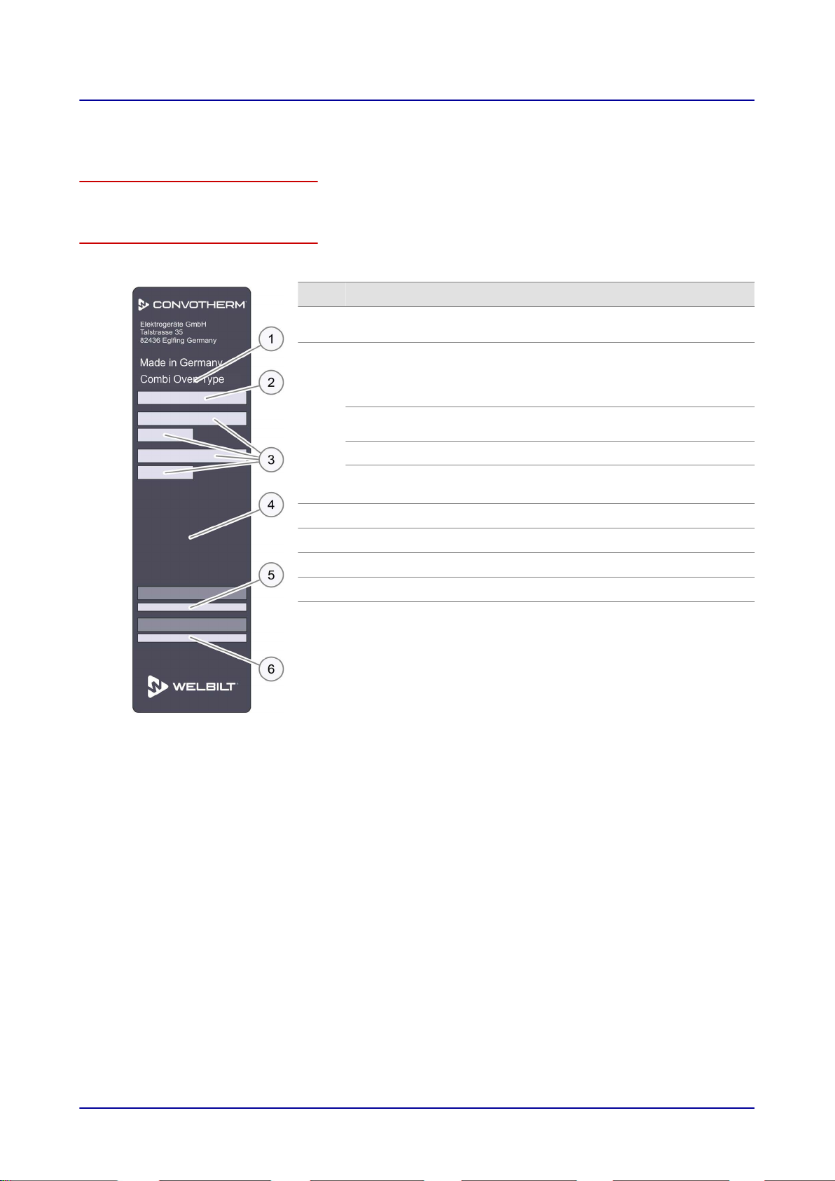
1.2 Identifying your combi oven
Position of type plate
The type plate is located on the left-hand side of the combi oven.
Layout and structure of the type plate
You can use the type plate to identify your appliance. The type plate has the following layout:
Item Name
1
2
3
4
5
6
Name of appliance
Combi Oven
Trade name
Element: Meaning:
OES Electric appliance with water
injection
numbers xx.yy Appliance size
■
mini
■
mini 2in1
Appliance series
Electrical values
Appliance tests
Serial number
Part number
Installation manual 6
Page 7

1 General
1.3 Structure of customer documentation
Contents of customer documentation
The customer documentation for the combi oven includes the following documents:
■
Installation manual (this document)
■
User manual
■
Operating instructions for easyStart mode
■
Help facility included in the software (extracts from the user manual)
Structure of customer documentation
The following table shows the topics and structure of the customer documentation:
Topic Description See
Transportation Moving the combi oven Installation manual
Setting up the appliance■Setup options
■
How to set up the combi oven correctly
Installation
Putting into service How to prepare the combi oven for first-time use
Operation
Cleaning
Servicing
Removal from service How to take the combi oven out of operation Installation manual
Technical data
Dimensional drawings,
connection points
Checklists Installation checklists
■
Electrical connection
■
Water connection
■
Installing the ConvoClean fully automatic oven
cleaning system (optional)
■
Describes the user interface
■
Working procedures and operating steps
■
Cleaning instructions
■
Cleaning programs and cleaning tasks
■
Servicing schedule
■
Minor servicing tasks
■
Shelf options
■
Maximum load
The complete technical specification for the combi
oven
All dimensional drawings and connection points of
the combi oven
(intended for trained
professional staff;
see Requirements to
be met by personnel
User manual
(intended for un‐
trained staff and
trained professional
staff; see Require‐
ments to be met by
personnel)
User manual
Installation manual
Installation manual
)
Installation manual 7
Page 8
1 General
1.4 Essential reading relating to safety
Safety information in the customer documentation
Safety information relating to the combi oven mainly appears in the installation manual and the user
manual.
The installation manual contains the safety information for the tasks covered by the manual and which
are performed when moving, setting up and installing the appliance and when putting the appliance
into service and removing the appliance from service.
The user manual contains the safety information for the tasks covered by the manual and which are
performed during cooking, cleaning and servicing work.
The safety information contained in the user manual and installation manual must always be consid‐
ered to be part of the operating instructions. The safety information contained in the user manual and
installation manual must always be observed when performing tasks that go beyond merely operating
the software.
Parts of this document that must be read without fail
If you do not follow the information in this document, you risk potentially fatal injury and property dam‐
age.
To guarantee safety, all people who work with the combi oven must have read and understood the
following parts of this document before starting any work:
■
the chapter 'For your safety', see
■
the sections that describe the activity to be carried out
For your safety on page 15
Danger symbol
Danger symbol Meaning
Warns of potential injuries. Heed all the warning notices that appear af‐
ter this symbol to avoid potential injuries or death.
Form of warning notices
The warning signs are categorized according to the following hazard levels:
Hazard level Consequences Likelihood
Death / serious injury (irreversible) Immediate risk
Death / serious injury (irreversible) Potential risk
Minor injury (reversible) Potential risk
NOTICE Damage to property Potential risk
Installation manual 8
Page 9

1 General
1.5 About this installation manual
Purpose
This installation manual is intended for all people who work with the combi oven, and provides them
with the necessary information for proper and safe working when moving, setting up and installing the
appliance and when putting the appliance into service.
Who should read this manual
This installation manual is aimed at the following groups:
Name of target group Tasks
Equipment mover Conveying within the establishment
Service engineer
Electrical fitter Installing and removing the electrical supply
■
Setting up the appliance
■
Installing and removing the water connection
■
Installing the ConvoClean fully automatic oven cleaning system (option‐
al)
■
Putting the appliance into service and removing the appliance from
service
■
Customer guidance and instruction.
Chapters in the installation manual
The table below lists the chapters in this manual and summarizes their content and purpose:
Contents Purpose
General
Design and function
■
Shows you how to identify your combi oven
■
Provides guidance on using this installation manual
■
Specifies the intended use of the combi oven
■
Explains the functions of the combi oven and shows the position of its
components
For your safety Describes the hazards posed by the combi oven and suitable preven‐
tive measures
It is important that you read this chapter carefully.
Transportation
Setting up the appliance
■
Specifies the basic appliance dimensions
■
Specifies the requirements for the installation position
■
Explains how to convey the appliance to the installation position
■
Explains how to unpack the appliance and specifies the parts sup‐
plied with the appliance
■
Explains how to set up the combi oven
Installation Provides information on installing the:
■
Electrical connection
■
Water connection
■
ConvoClean fully automatic oven cleaning system (optional)
Putting into service Explains the procedure for preparing the appliance for first-time use
Removal from service, dis‐
posal
■
Explains the procedure for taking appliance out of service
■
Contains disposal instructions
Technical data Contains the technical data
Installation manual 9
Page 10

1 General
Contents Purpose
Dimensional drawings and
Contains the dimensional drawings and connection plans.
connection diagrams
Checklists and completion
of installation
■
Contains the checklists for
■
Installation
■
Safety devices and warnings
■
Customer guidance and instruction
■
Contains information on the warranty and explains the completion
procedure using the checklists
Notation for decimal points
A decimal point is always used in order to achieve international standardization.
Installation manual 10
Page 11
131 32 4 5 6 8 9 1110 127
17 1516 1418
2 Design and function
2 Design and function
Purpose of this chapter
This chapter describes the design and construction of the combi oven and explains its functions.
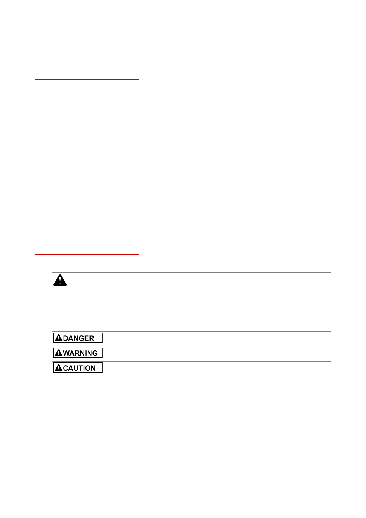
2.1 Design and function of the combi oven (6.06/6.10/10.10 mini)
Layout of the combi oven
The following figure shows the 6.06 mini combi oven (representative of all appliance sizes):
Components of the combi ovens and their function
The components of the combi oven have the following function:
No. Name Function
1
Ventilation port External air intake for removing the moisture from the cooking
chamber
2
3
4
5
6
7
Air vent Lets vapour escape
Operating panel Used for operating the combi oven
Suction panel Distributes the heat inside the cooking chamber
Rack Holds standard-sized food containers
Oven light Illuminates the cooking chamber
Core temperature probe
Used for measuring the core temperature
(optional)
8
9
Appliance door Closes the cooking chamber
Door handle
■
Opens and closes the appliance door
■
Venting position for opening the combi oven door safely (with
safety catch option)
10
11
12
13
14
15
Ventilation slots Used for ventilation
Rear wall Covers the wiring compartment of the combi oven
Top box Covers the controller electronics of the combi oven
Outer casing Used for covering the appliance interior
Connecting bracket Used for covering the connection area
Hole between the front
Used for venting air out of appliance
appliance feet
Installation manual 11
Page 12
131 32 8 9 1110 127
19 1617 15 14
4 5 6
21
20 18
2 Design and function
No. Name Function
16
17
18
Cooking chamber Contains the food during cooking operation
Appliance feet
■
Used for setting up and adjusting level of appliance
■
Height adjustable on 10.10 mini
Type plate Used for identifying the combi oven
Material
The interior and exterior structure of the combi oven is made of stainless steel.
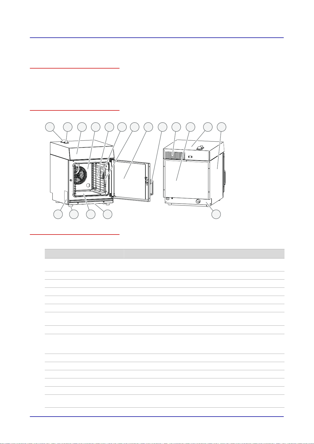
2.2 Layout and function of the combi oven (6.10 mini 2in1)
Layout of the combi oven
The following diagram shows the combi oven:
Components of the combi ovens and their function
Installation manual 12
The components of the combi oven have the following function:
No. Name Function
1
2 Ventilation ports External air intake for removing the moisture from the cooking
chamber
2
3
4
5
6
7
8
2 air vents Lets vapour escape
Operating panel Used for operating the combi oven
Suction panel Distributes the heat inside the cooking chamber
Rack Holds standard-sized food containers
Oven light Illuminates the cooking chamber
Core temperature probe Used for measuring the core temperature
Appliance door Closes the cooking chamber
Page 13

2 Design and function
No. Name Function
9
10
11
12
13
14
15
16
17
18
19
20
21
Door handle Opens and closes the appliance door
Ventilation slots Used for ventilation
Rear wall Covers the wiring compartment of the combi oven
Top box Covers the controller electronics of the combi oven
Outer casing Used for covering the appliance interior
Connecting bracket Used for covering the connection area
Wall bracket Used to fix the combi oven to a wall
Stand Brings the appliance up to working height
Ventilation slots in the
appliance floor
Cooking chamber 1 Contains the food during cooking operation
Cooking chamber 2 Contains the food during cooking operation
Type plate Used for identifying the combi oven
Cleaning agent drawers Contain the cleaning agent and rinse aid for fully automatic clean‐
Used for venting air out of appliance
ing ConvoClean system
Material
The interior and exterior structure of the combi oven is made of stainless steel.
Installation manual 13
Page 14
2 Design and function
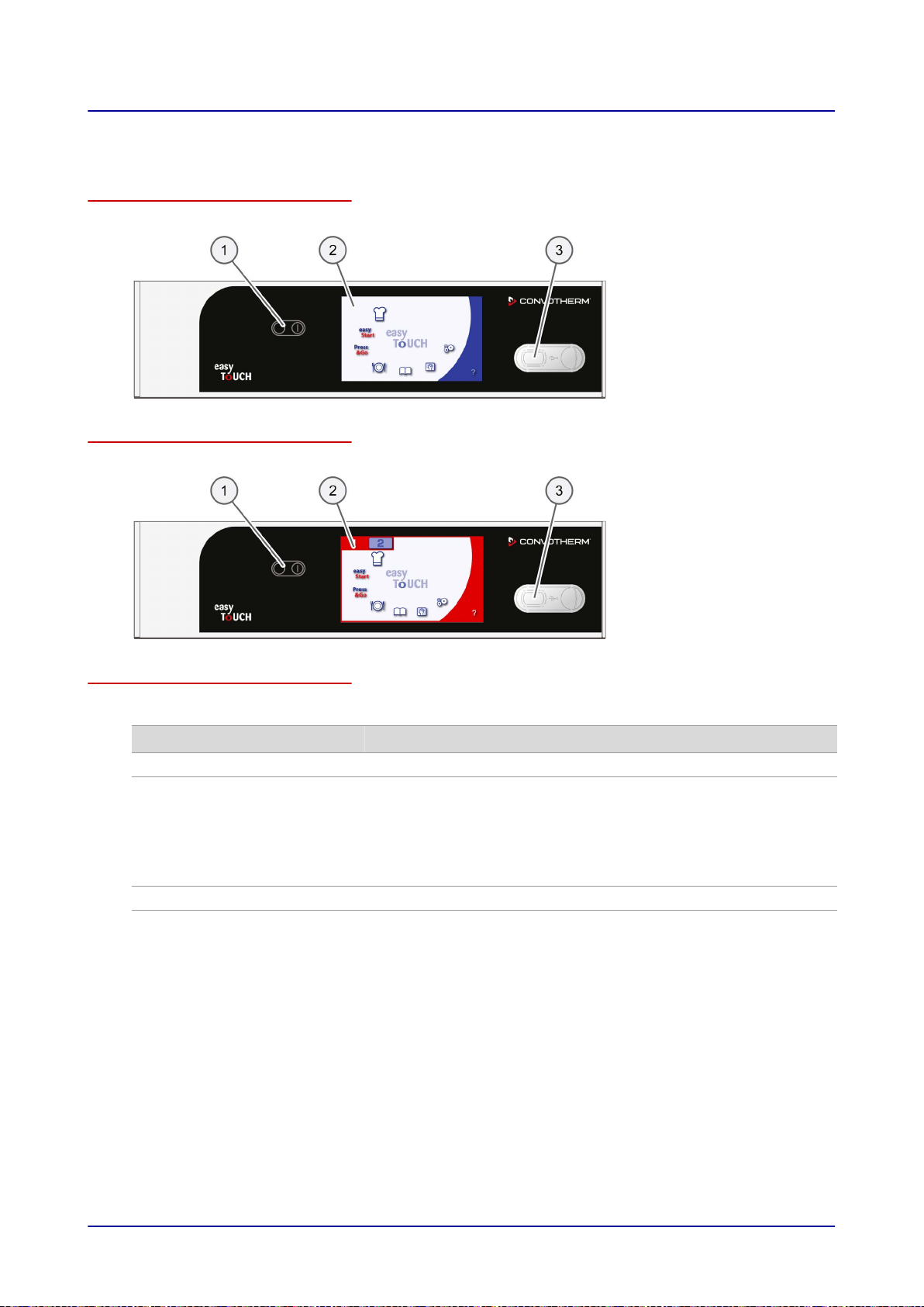
2.3 Layout and function of the operating panel
Layout of the operating panel
The following illustration shows the operating panel:
Layout of the operating panel (6.10 mini 2in1)
The following illustration shows the operating panel:
Elements of the operating panel
The elements of the operating panel have the following function:
No. Name Function
1
2
Main switch Switches the combi oven on and off
Touchscreen Central control of combi oven
■
Appliance operated by touching icons on control panel pages
■
Status displays
Only for 6.10 mini 2in1:
Central control of both cooking chambers of the combi oven
■
Switching from one cooking chamber to the other
3
USB port For connecting external appliances
Installation manual 14
Page 15

3 For your safety
3 For your safety
Purpose of this chapter
This chapter provides you with all the information you need in order to use the combi oven safely with‐
out putting yourself or others at risk.
This is a particularly important chapter that you should read through carefully.
3.1 Basic safety code
Object of this safety code
This safety code aims to ensure that all persons who use the combi oven have a thorough knowledge
of the hazards and safety precautions, and that they follow the warning notices given in the user man‐
ual and on the combi oven. If you do not follow this safety code, you risk potentially fatal injury and
property damage.
Referring to the user manuals included in the customer documentation
Follow the instructions below:
■
Read in full the chapter 'For Your Safety' and the chapters that relate to your work.
■
Always keep to hand the manuals included in the customer documentation for reference.
■
Pass on the user manuals included in the customer documentation with the combi oven if it
changes ownership.
Ground rules for installation
Installation must comply with all national and regional laws and regulations and comply with the local
regulations of the relevant utility companies and local authorities and with other relevant requirements.
Working with the combi oven
Follow the instructions below:
■
Only those persons who satisfy the requirements stipulated in this user manual are permitted to
use the combi oven.
■
Only use the combi oven for the specified use. Never, under any circumstances, use the combi
oven for other purposes that may suggest themselves.
■
Take all the safety precautions specified in this user manual and on the combi oven. In particular,
use the prescribed personal protective equipment.
■
Only stand in the working positions specified.
■
Do not make any changes to the combi oven, e.g. removing parts or fitting un-approved parts. In
particular, you must not disable any safety devices.
Installation manual 15
Page 16

3 For your safety
More on this ...
Related topics
Intended use of your combi oven 17
Warning signs on the combi oven (6.06/6.10/10.10 mini) 18
Warning signs on the combi oven (6.10 mini 2in1) 20
Hazards and safety precautions when moving the appliance 22
Hazards and safety precautions when setting up the appliance 23
Hazards and safety precautions during installation 25
Hazards and safety precautions when putting the appliance into service 27
Hazards and safety precautions when removing the appliance from service 30
Safety devices (6.06/6.10/10.10 mini) 33
Safety devices (6.10 mini 2in1) 35
Requirements to be met by personnel, working positions 37
Personal protective equipment 39
Installation manual 16
Page 17

3 For your safety
3.2 Intended use of your combi oven
Intended use
■
The combi oven is designed and built solely for cooking different foodstuffs in standard-sized food
containers (e.g.
steam (non-pressurized superheated steam) are used for this purpose.
■
The food containers can be made of stainless steel, ceramic, plastic, aluminium, enamelled steel or
glass. Glass food containers must not exhibit any form of damage.
■
The combi oven is intended solely for professional, commercial use.
Restrictions on use
Some materials are not allowed to be heated in the combi oven:
■
NO dry powder or granulated material
■
NO highly flammable substances or objects with a flash point below 270 °C, such
mable oils, fats or plastics
■
NO food in sealed tins or jars
Requirements to be met by personnel
■
The combi oven must only be operated and installed by personnel who satisfy specific require‐
ments. Please refer to 'Requirements to be met by personnel, working positions' on page
the training and qualifications requirements.
■
Personnel must be aware of the risks and regulations associated with handling heavy loads.
Gastronorm containers, standard baking trays). Steam, convection and combi-
as highly flam‐
37 for
Requirements relating to the operating condition of the combi oven
■
The combi oven must only be operated when all safety devices and protective equipment are fitted,
in working order and fixed properly in place.
■
The manufacturer regulations for operating and servicing the combi oven must be observed.
■
The combi oven must not be loaded over the maximum permissible loading weight for the given
model or shelf allowance; see
'Technical Data' on page 92.
Requirements relating to the operating environment of the combi oven
Specified operating environment for the combi oven
■
The ambient temperature lies between
■
NOT a toxic or potentially explosive atmosphere
■
Dry kitchen floor to reduce the risk of accidents
+4 °C and +35 °C
Specified properties of the installation location
■
NO fire alarm, NO sprinkler system directly above the appliance
■
NO flammable materials, gases or liquids above, on, beneath or in the vicinity of the appliance
Mandatory restrictions on use
■
Shelter from rain and wind must be provided if operated outdoors
■
Appliance must NOT be shifted or moved during use
Cleaning requirements
■
Use only cleaning agents that have been approved by the manufacturer.
■
High-pressure cleaners must NOT be used for cleaning.
■
Water jets must NOT be used for cleaning the exterior. The water spray from the recoil hand show‐
er must only be used for cleaning the cooking chamber.
■
The combi oven must NOT be treated with acids or exposed to acid fumes, except for the purpose
of descaling the cooking chamber and the boiler by an authorized service company in accordance
with the manufacturer's instructions.
Installation manual 17
Page 18
1
2
1
3 For your safety
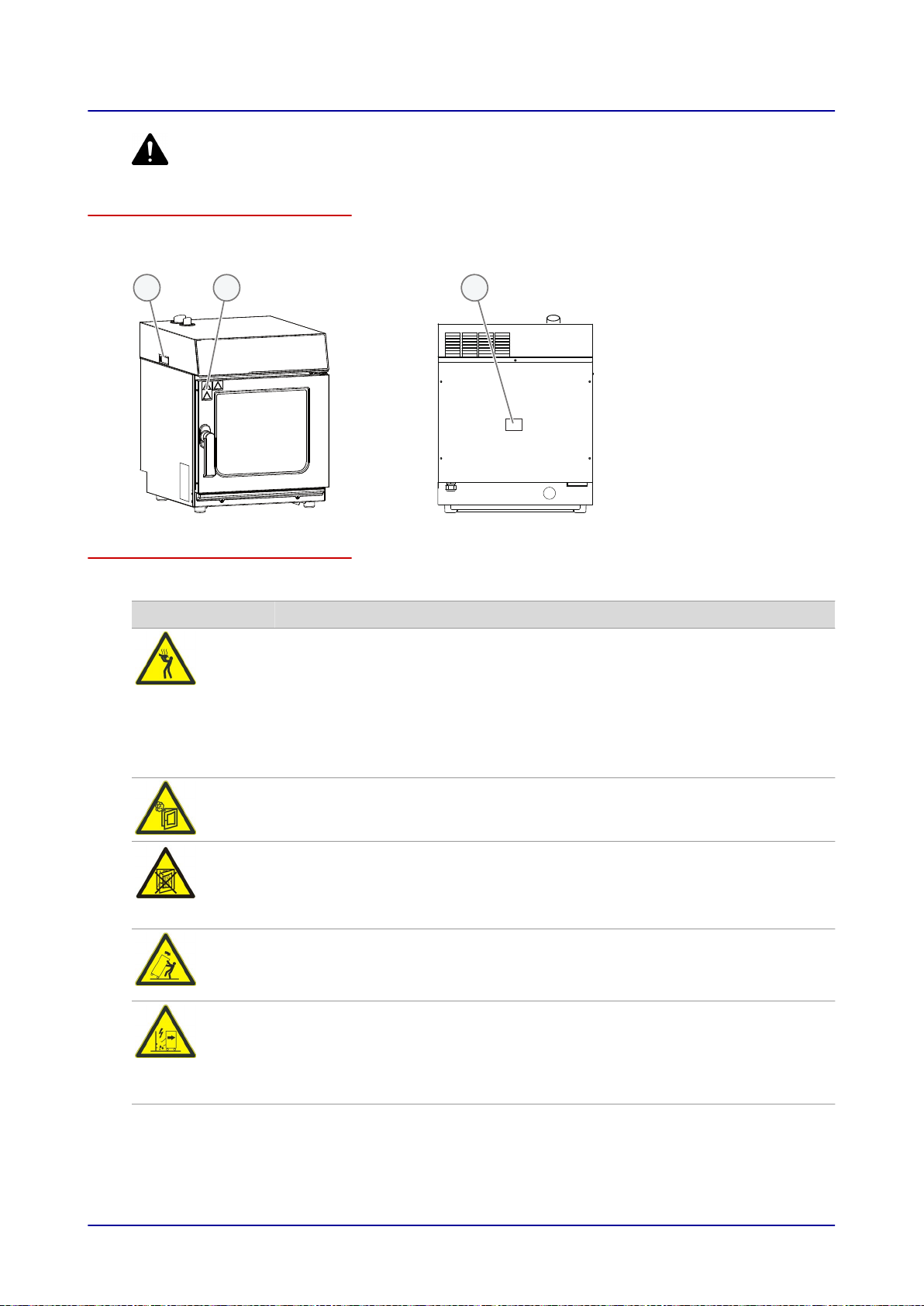
3.3 Warning signs on the combi oven (6.06/6.10/10.10 mini)
Where are the warning signs fitted?
The following figure shows the 6.06 mini combi oven (representative of all appliance sizes).
The warning signs are located in the following positions:
Warnings on the appliance door
The following warning signs (2) are fitted on the appliance door above the door handle:
Warning sign Description
Warning of hot food, hot food containers and hot liquids
There is a risk of burns from hot food and hot food containers if food containers
tip out of the shelf levels or food slips off food containers that are not held level.
This risk is particularly high for shelf levels that lie above the sightline of the
user.
Spillage of hot liquid foods can result in scalds if the upper shelf levels are loa‐
ded with liquids or foods that produce liquid during cooking. Do not use shelf
levels that lie above your sightline for liquid foodstuffs or food that will liquefy
during cooking.
Hot steam and vapour hazard warning
There is a risk of scalding from hot steam and vapour escaping when the appli‐
ance door is opened.
Only for ConvoClean system option
Warning of corrosive cleaning agents injected into oven
There is a risk of chemical burns or irritation to skin, eyes and respiratory sys‐
tem from contact with sprayed cleaning agents and their vapours if the appli‐
ance door is opened during fully automatic cleaning by the ConvoClean
Only for a mobile supporting structure
Tipping or toppling warning for combi oven
There is a risk of the combi oven toppling over if moved. Always take great care
when moving the combi oven.
Only for a mobile supporting structure
Damage or detachment warning for appliance connections
There is a risk of the appliance connections being damaged or detached if the
combi oven is moved. Always ensure there is enough length in the supply ca‐
bles and pipes when moving the combi oven. After moving, always secure the
combi oven against rolling away.
system.
Installation manual 18
Page 19

3 For your safety
Warning signs on the combi oven case
The following warning signs (1) are fitted on the case of the combi oven:
Warning sign Description
High voltage / electric shock hazard warning
There is a risk of electric shock from live parts if the safety cover is opened.
Installation manual 19
Page 20
1
1
2
2
3
3 For your safety
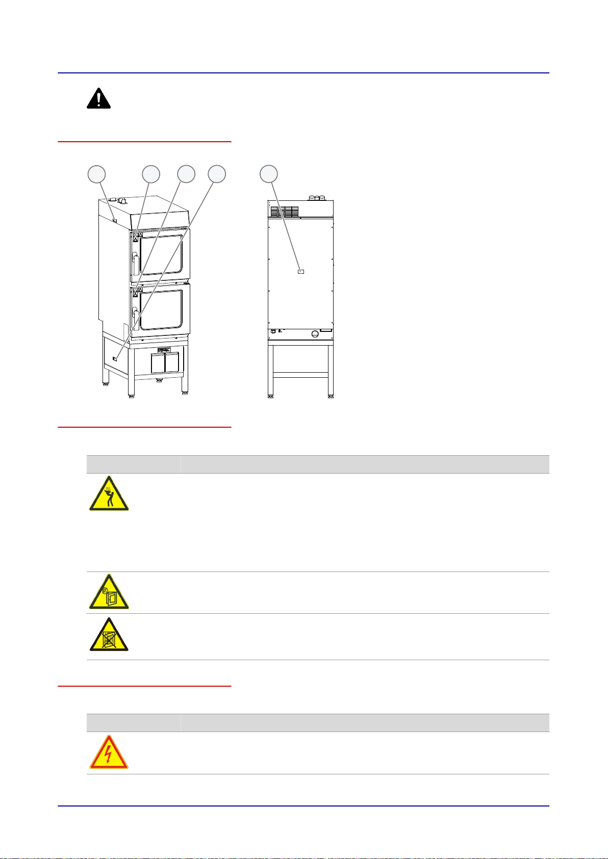
3.4 Warning signs on the combi oven (6.10 mini 2in1)
Where are the warning signs fitted?
The warning signs are located in the following positions on the combi oven:
Warnings on the appliance door
The following warning signs (2) are fitted on the appliance doors above the door handles:
Warning sign Description
Warning of hot food, hot food containers and hot liquids
There is a risk of burns from hot food and hot food containers if food containers
tip out of the shelf levels or food slips off food containers that are not held level.
This risk is particularly high for shelf levels that lie above the sightline of the
user.
Spillage of hot liquid foods can result in scalds if the upper shelf levels are loa‐
ded with liquids or foods that produce liquid during cooking. Do not use shelf
levels that lie above your sightline for liquid foodstuffs or food that will liquefy
during cooking.
Hot steam and vapour hazard warning
There is a risk of scalding from hot steam and vapour escaping when the appli‐
ance door is opened.
Warning of corrosive cleaning agents injected into oven
There is a risk of chemical burns or irritation to skin, eyes and respiratory sys‐
tem from contact with sprayed cleaning agents and their vapours if the appli‐
ance door is opened during fully automatic cleaning by the ConvoClean
system.
Warning signs on the combi oven case
The following warning signs (1) are fitted on the case of the combi oven:
Warning sign Description
High voltage / electric shock hazard warning
There is a risk of electric shock from live parts if the safety cover is opened.
Installation manual 20
Page 21

3 For your safety
Warning signs on the case of the cleaning agent drawers
The following warning sign (3) is mounted on the case of the cleaning agent drawers:
Warning sign Description
High voltage / electric shock hazard warning
There is a risk of electric shock from live parts if the safety cover is opened.
Installation manual 21
Page 22

3 For your safety
3.5 Hazards and safety precautions when moving the appliance
Safety hazard: moving heavy weights
When moving the appliance, be aware of the following hazards and take the specified preventive ac‐
tions:
Danger Where or in what situations
Preventive action Safety device
does the hazard arise?
Risk of injury from over‐
stressing your body
When moving the appliance
■
Use suitable lifting gear
■
Do not exceed safety lim‐
its for lifting and carrying
■
Use lifting straps
■
Wear personal protective
equipment
Safety hazard: mechanical parts of the appliance
When moving the appliance, be aware of the following hazards and take the specified preventive ac‐
tions:
Danger Where or in what situations
Preventive action Safety device
does the hazard arise?
Risk of body parts be‐
ing crushed if the appli‐
ance is dropped
When moving the appliance
■
Use suitable handling
gear
■
Move the appliance slow‐
ly and carefully, and se‐
cure it against tipping
over
■
Make sure center of grav‐
ity is balanced
■
Avoid jolts
Risk of body parts be‐
ing crushed if the appli‐
ance tips over or falls
off
When placing the appliance
down on the supporting sur‐
face
Always observe the re‐
quirements for the support‐
ing surface while setting up
the appliance; see
Require‐
ments for the installation lo‐
cation on page 44
None
None
None
Installation manual 22
Page 23

3 For your safety
3.6 Hazards and safety precautions when setting up the appliance
Safety hazard: moving heavy weights
When setting up the appliance, be aware of the following hazards and take the specified preventive
actions:
Danger Where or in what situations
does the hazard arise?
Risk of injury from over‐
When moving the appliance
stressing your body
Preventive action Safety device
■
Use suitable lifting equip‐
None
ment for placing the ap‐
pliance on the work sur‐
face, on the stand, in the
stacking kit or in the in‐
stallation location (de‐
pendent on appliance
size)
■
Always use the correct
number of persons and
observe the limits speci‐
fied for lifting and carrying
when adjusting the appli‐
ance position
■
Observe the local occu‐
pational safety regula‐
tions
■
Wear personal protective
equipment
For 10.10 mini / 6.10 mini
2in1:
■
Use lifting straps to take
the appliance off the pal‐
let
Installation manual 23
Page 24

3 For your safety
Safety hazard: mechanical parts of the appliance
When setting up the appliance, be aware of the following hazards and take the specified preventive
actions:
Danger Where or in what situations
does the hazard arise?
Risk of body parts be‐
When lifting the appliance
ing crushed if the appli‐
ance is dropped
For 6.06/6.10/10.10
mini:
Risk of crushing due to
loss of appliance stabili‐
ty if the appliance is
mounted on a stand or
in a stacking kit
Risk of body parts be‐
ing crushed if the appli‐
■
When installing the appli‐
ance on the oven stand
■
When fitting the appliances
in the stacking kit
■
When a heavy load is ap‐
plied to the top appliance
alone
When installing the appliance
on the floor
ance tips over or falls
off
Risk of cuts from sharp
edges
When handling sheet-metal
parts
Preventive action Safety device
■
Make sure center of grav‐
None
ity is balanced
■
Avoid jolts
■
Never exert an extra
pressure on the applian‐
ces, e.g. by leaning on
Parking brake
on wheeled
stacking kit
the open appliance door
■
Before fitting the applian‐
ces in a wheeled stacking
kit, secure the stacking kit
by engaging the parking
brake on the wheels
■
Always fit the bottom ap‐
pliance first in the stack‐
ing kit
■
Make sure that the appli‐
ances are seated correct‐
ly in the stacking kit
Always observe the re‐
None
quirements for the support‐
ing surface while setting up
the appliance; see
Require‐
ments for the installation lo‐
cation on page 44
■
Exercise caution when
None
performing these tasks
■
Wear personal protective
equipment as specified in
safety regulations
Installation manual 24
Page 25

3 For your safety
3.7 Hazards and safety precautions during installation
Safety hazard: electrical power
When installing the appliance, be aware of the following hazards and take the specified preventive ac‐
tions:
Danger Where or in what situations
does the hazard arise?
Risk of electric shock
from live parts
Risk of electric shock
from live parts
■
Under covers
■
Under the operating panel
■
On the power supply cable
■
On the appliance and on
adjacent metal parts
■
On the appliance and on
adjacent metallic accesso‐
ries
Risk of electric shock
from incorrect water
connection
■
In the entire work area, as
soon as the water pipe
bursts or starts leaking
Preventive action Safety device
■
Work on the electrical
Covers
system must only be per‐
formed by qualified elec‐
tricians from an author‐
ized service company
■
Professional working
Before removing the cov‐
Covers
ers:
■
Switch off all connections
to the power supply
■
Take protective meas‐
ures at every power
switch to ensure that the
power cannot be switch‐
ed on again
■
If the appliance has previ‐
ously been connected to
the electricity supply, wait
15 minutes to allow the
DC bus capacitors to dis‐
charge
■
Make sure that the appli‐
ance is de-energized
■
Ensure that all electrical
Covers
connections are in perfect
condition and fixed se‐
curely before putting the
appliance into service
■
Before preparing the ap‐
pliance for first-time use,
make sure that the appli‐
Equipotential
bonding sys‐
tem
ance, including all metal‐
lic accessories, is con‐
nected to a equipotential
bonding system.
■
Use a fixed connection
■
Make sure that the water
none
pressure of the water
supply is compatible with
the pressure specified on
the appliance
■
Use suitable pipes and
hoses in accordance with
applicable regulations
(EN 61770 in countries
where European stand‐
ards apply)
Installation manual 25
Page 26

3 For your safety
Safety hazard: mechanical parts of the appliance
When installing the appliance, be aware of the following hazards and take the specified preventive ac‐
tions:
Danger Where or in what situations
Preventive action Safety device
does the hazard arise?
Risk of cuts from sharp
edges
When handling sheet-metal
parts
■
Exercise caution when
performing these tasks
■
Wear personal protective
None
equipment as specified in
safety regulations
Safety hazard: cleaning agent
When installing the appliance, be aware of the following hazards and take the specified preventive ac‐
tions:
Danger Where or in what situations
Preventive action Safety device
does the hazard arise?
Risk of chemical burns
or irritation to skin, eyes
and respiratory system
from contact with clean‐
ing agents and their va‐
pours.
When corrosive cleaning
agents are used
For 6.06/6.10/10.10 mini with
ConvoClean system option:
When fitting the cleaning sys‐
tem
Only use those cleaning
agents specified under
Cleaning agents in the
'Cleaning and Servicing'
chapter of the user manual.
■
Wear personal protective
equipment
■
Observe the labels on the
cleaning agents and the
None
None
relevant safety data‐
sheets
For 6.10 mini 2in1:
When handling the cleaning
agent drawer and rinse aid
drawer
■
Wear personal protective
equipment
■
Close the cleaning agent
drawer and rinse aid
None
drawer carefully without
jolting to avoid any clean‐
ing agent slopping out.
Installation manual 26
Page 27

3 For your safety
3.8 Hazards and safety precautions when putting the appliance into service
Safety hazard: electrical power
When preparing the appliance for first-time use, be aware of the following hazards and take the speci‐
fied preventive actions:
Danger Where or in what situations
does the hazard arise?
Risk of electric shock
from live parts
Risk of electric shock
from live parts
■
Under covers
■
Under the operating panel
■
On the power supply cable
■
On the appliance and on
adjacent metal parts
■
On the appliance and on
adjacent metallic accesso‐
ries
Preventive action Safety device
■
Work on the electrical
Covers
system must only be per‐
formed by qualified elec‐
tricians from an author‐
ized service company
■
Professional working
Before removing the cov‐
Covers
ers:
■
Switch off all connections
to the power supply
■
Take protective meas‐
ures at every power
switch to ensure that the
power cannot be switch‐
ed on again
■
If the appliance has previ‐
ously been connected to
the electricity supply, wait
15 minutes to allow the
DC bus capacitors to dis‐
charge
■
Make sure that the appli‐
ance is de-energized
■
Ensure that all electrical
Covers
connections are in perfect
condition and fixed se‐
curely before putting the
appliance into service
■
Before preparing the ap‐
pliance for first-time use,
make sure that the appli‐
Equipotential
bonding sys‐
tem
ance, including all metal‐
lic accessories, is con‐
nected to a equipotential
bonding system.
Installation manual 27
Page 28

3 For your safety
Safety hazard: moving appliances supported on a wheeled platform
Danger Where or in what situations
does the hazard arise?
All specified hazards While appliances are being
moved on a wheeled platform
Risk of crushing of
body parts
Pinch point hazard for
hands and feet
Risk of scalding from
hot wastewater
Risk of scalding from
hot liquid food
Risk of electric shock
from live parts
Risk of skin and eye ir‐
ritation from contact
While appliances are being
moved on a wheeled platform
While appliances are being
moved on a wheeled platform
While appliances are being
moved on a wheeled platform
While appliances are being
moved on a wheeled platform
While appliances are being
moved on a wheeled platform
While appliances are being
moved on a wheeled platform
with cleaning products
Risk of tripping from ex‐
posed cables and pipes
Risk of falling on wet
floor caused by waste‐
water
Risk of falling on wet
floor caused by clean‐
ing fluids
While cleaning behind appli‐
ances when pulled forward
■
While cleaning behind ap‐
pliances when pulled for‐
ward
■
In front of the appliances
■
While cleaning behind ap‐
pliances when pulled for‐
ward
■
In front of the appliances
Preventive action Safety device
■
Before moving applian‐
ces with a fixed wastewa‐
Retaining de‐
vice
ter connection, discon‐
nect the drain pipe
■
Disconnect the appliance
from the electrical supply
before moving it
■
Before moving (for in‐
stance to clean the case
of the combi ovens or to
clean the floor), check
whether the retaining de‐
vice which restricts the
radius of movement of
the platform plus appli‐
ance is connected.
■
When moving the appli‐
ance, take care not to
wheel over the electrical
supply cables or the wa‐
ter pipes
■
Watch out for the con‐
None
necting cables and pipes.
■
Use at least two people
to move it
■
Keep the appliance doors
None
closed
■
Let the appliance
None
cool down
■
Wipe up immediately any
water spillages
■
Wear protective clothing
■
Always remove any food
None
from the appliances be‐
fore moving them
■
Watch out for connected
None
electrical cables and wa‐
ter pipes
■
Make sure that the con‐
None
necting lines and pipes
are long enough
■
Keep cleaning-fluid canis‐
ters closed when moving
the base
■
Exercise caution when
None
performing this action
■
Wipe up immediately any
None
water spillages
■
Make sure that the con‐
necting lines and pipes
are long enough
■
Keep the cleaning-fluid
None
canisters closed when
moving appliances
Installation manual 28
Page 29

3 For your safety
Additional safety hazards when putting the appliance into service
When preparing the appliance for first-time use, read and follow the safety information given in this
chapter and also the following topics in the chapter 'For your safety' in the user manual:
■
Hazards and safety precautions during operation
■
Hazards and safety precautions during cleaning
■
Personal protective equipment
Installation manual 29
Page 30

3 For your safety
3.9 Hazards and safety precautions when removing the appliance from service
Safety hazard: electrical power
When taking the appliance out of service, be aware of the following hazards and take the specified
preventive actions:
Danger Where or in what situations
Preventive action Safety device
does the hazard arise?
Risk of electric shock
from live parts
■
Under covers
■
Under the operating panel
■
Work on the electrical
system must only be per‐
formed by qualified elec‐
tricians from an author‐
ized customer service
company
■
Professional working
Before removing the cov‐
ers:
■
Switch off all connections
to the power supply
■
Take protective meas‐
ures at every power
switch to ensure that the
power cannot be switch‐
ed on again
■
Wait 15
minutes to allow
the DC bus capacitors to
discharge
■
Make sure that the appli‐
ance is de-energized
Safety hazard: moving heavy weights
When taking the appliance out of service, be aware of the following hazards and take the specified
preventive actions:
Covers
Danger Where or in what situations
does the hazard arise?
Risk of injury from over‐
When moving the appliance
stressing your body
Installation manual 30
Preventive action Safety device
■
Use suitable lifting gear
■
Do not exceed safety lim‐
None
its for lifting and carrying
■
Use lifting straps
■
Wear personal protective
equipment
Page 31

3 For your safety
Safety hazard: moving appliances supported on a wheeled platform
Danger Where or in what situations
does the hazard arise?
All specified hazards While appliances are being
moved on a wheeled platform
Risk of crushing of
body parts
Pinch point hazard for
hands and feet
Risk of scalding from
hot wastewater
Risk of scalding from
hot liquid food
Risk of electric shock
from live parts
Risk of skin and eye ir‐
ritation from contact
While appliances are being
moved on a wheeled platform
While appliances are being
moved on a wheeled platform
While appliances are being
moved on a wheeled platform
While appliances are being
moved on a wheeled platform
While appliances are being
moved on a wheeled platform
While appliances are being
moved on a wheeled platform
with cleaning products
Risk of tripping from ex‐
posed cables and pipes
Risk of falling on wet
floor caused by waste‐
water
Risk of falling on wet
floor caused by clean‐
ing fluids
While cleaning behind appli‐
ances when pulled forward
■
While cleaning behind ap‐
pliances when pulled for‐
ward
■
In front of the appliances
■
While cleaning behind ap‐
pliances when pulled for‐
ward
■
In front of the appliances
Preventive action Safety device
■
Disconnect the appliance
from the electrical supply
Retaining de‐
vice
before moving it
■
Before moving applian‐
ces with a fixed wastewa‐
ter connection, discon‐
nect the drain pipe
■
Before moving (e.g. to
access the back of the
appliance), check that the
retaining device is con‐
nected. This device re‐
stricts the range of move‐
ment of the platform sup‐
porting the appliance.
■
When moving the appli‐
ance, take care not to
wheel over the electrical
supply cables or the wa‐
ter pipes
■
Watch out for the con‐
None
necting cables and pipes.
■
Use at least two people
to move it
Keep the appliance doors
None
closed
■
Let the appliance
None
cool down
■
Wipe up immediately any
water spillages
■
Wear personal protective
clothing
Always remove any food
None
from the appliances before
moving them
Watch out for connected
None
electrical cables and water
pipes.
■
Make sure that the con‐
None
necting lines and pipes
are long enough
■
Keep cleaning-fluid canis‐
ters closed when moving
the base
Exercise caution when per‐
None
forming this action
■
Wipe up immediately any
None
water spillages
■
Make sure that the con‐
necting lines and pipes
are long enough
Keep the cleaning-fluid
None
canisters closed when
moving appliances
Installation manual 31
Page 32

3 For your safety
Safety hazard: mechanical parts of the appliance
When taking the appliance out of service, be aware of the following hazards and take the specified
preventive actions:
Danger Where or in what situations
For 6.10 mini 2in1:
Risk of body parts be‐
ing crushed if the appli‐
ance is dropped
For 6.06/6.10/10.10
mini:
Risk of crushing due to
loss of appliance stabili‐
ty if the appliance is
mounted in a stand or
in a stacking kit
Risk of cuts from sharp
edges
Safety hazard: cleaning agent
does the hazard arise?
When lifting the appliance
■
When removing the appli‐
ance from the stand
■
When removing the appli‐
ances from the stacking kit
■
When a heavy load is ap‐
plied to the top appliance
alone
When handling sheet-metal
parts
Preventive action Safety device
■
Make sure center of grav‐
None
ity is balanced
■
Avoid jolts
■
Never exert an extra
pressure on the applian‐
ces, e.g. by leaning on
Parking brake
on wheeled
stacking kit
the open appliance door
■
Before removing the ap‐
pliances from a wheeled
stacking kit, secure the
stacking kit by engaging
the parking brake on the
wheels
■
Always remove the top
appliance first from the
stacking kit
■
Exercise caution when
None
performing these tasks
■
Wear personal protective
equipment as specified in
safety regulations
Danger Where or in what situations
does the hazard arise?
Risk of chemical burns
or irritation to skin, eyes
and respiratory system
from contact with clean‐
■
When removing the clean‐
ing system
■
When disposing of the ap‐
pliance
ing agents and their va‐
pours.
Preventive action Safety device
■
Wear personal protective
None
equipment
■
Observe the labels on the
cleaning agents and the
relevant safety data‐
sheets
Installation manual 32
Page 33

1 2 3 4
3 For your safety
3.10 Safety devices (6.06/6.10/10.10 mini)
Meaning
The combi oven has a number of safety devices to protect the user from hazards. It is absolutely es‐
sential that all safety devices are fitted, secured correctly and in working order when operating the
combi oven.
Position
The following figure shows the location of the safety devices on a 6.06 mini combi oven with the safety
catch option (representative of all appliance sizes):
Functions
The following table enumerates all the safety devices on the combi oven, explains their function and
describes the check procedure:
No. Safety device Function Check
1
Covers can only be re‐
moved using a tool
■
Prevents live parts from be‐
ing touched accidentally
■
Prevents access to the mov‐
ing fan from the wiring com‐
partment
2
Appliance door Protects the user and outside
environment from hot steam
For the safety catch op‐
tion:
Appliance door with
magnetic switch
Magnetic door switch (electri‐
cal door sensor):
■
When the appliance door is
opened, the switch stops:
■
rotation of the fan wheel
(comes to a stop after a
few seconds)
■
operation of the heating el‐
ement
■
Distribution of the cleaning
agent by the fully automat‐
ic oven cleaning system
(for ConvoClean system
option)
■
Prompt to close the appli‐
ance door
Check that the covers are in
place
Check regularly for scratches,
cracks, indentations etc. and
replace door if any are found
Check magnetic door switch
at low temperature
Action:
■
Open the appliance door
fully
■
Press Start
Result:
Motor must not start up
Installation manual 33
Page 34

3 For your safety
No. Safety device Function Check
3
4
5
(no
picture)
6
(no
picture)
7 (installed
by
customer)
8
(no
picture)
For the safety catch op‐
tion:
On-latch position of ap‐
pliance door
Suction panel in cook‐
ing chamber; can only
be removed using a
tool
for ConvoClean system
option:
Automatic safety rins‐
ing after power failure
in case cleaning agent
left in combi oven
For ConvoClean sys‐
tem option:
Spray-guard
Disconnector
When installing on a
wheeled supporting
structure:
Retaining device
Prevents scalding of user's
face and hands from escaping
steam
Prevents access to the moving
fan and ensures good heat dis‐
tribution
Re-starts fully automatic clean‐
ing (ConvoClean system) in a
defined state after power fail‐
ure
Stops the cleaning agent being
injected during fully automatic
cleaning (ConvoClean system)
when the appliance door is
opened
Prompt to close the appliance
door
■
Installed by the customer
close to the appliance; easily
visible and accessible, 3pole action, minimum contact
separation 3 mm.
■
Used to disconnect the appli‐
ance from the power supply
during cleaning, repair and
servicing work and in a haz‐
ardous situation
Restricts the range of move‐
ment of the assembly (support‐
ing structure plus appliance) at
the customer's site.
When appliance is at low tem‐
perature, check door positions
as described in '
Opening and
closing the appliance door
safely' in the user manual
See
'Removing and fitting the suc‐
tion panel' in the user manual
for further details.
Test is a software function
Test is a software function
Action:
■
Trip the disconnector
■
Check at the -X10 terminal
strip on the appliance that
none of the three phases
carry a live voltage
Check that the retaining de‐
vice is connected
Installation manual 34
Page 35

3
1
2
3 For your safety
3.11 Safety devices (6.10 mini 2in1)
Meaning
The combi oven has a number of safety devices to protect the user from hazards. It is absolutely es‐
sential that all safety devices are fitted, secured correctly and in working order when operating the
combi oven.
Position
The following diagram shows the location of the safety devices:
Functions
The following table enumerates all the safety devices on the combi oven, explains their function and
describes the check procedure:
No. Safety device Function Check
1
Covers can only be re‐
moved using a tool
■
Prevents live parts from be‐
ing touched accidentally
■
Prevents access to the mov‐
Check that the covers are in
place
ing fan from the wiring com‐
partment
2
Appliance door Protects the user and outside
environment from hot steam
Check regularly for scratches,
cracks, indentations etc. and
replace door if any are found
3
4
(no
picture)
Suction panel in cook‐
ing chamber; can only
be removed using a
tool
Automatic safety rins‐
ing after power failure
in case cleaning agent
left in combi oven
Prevents access to the moving
fan and ensures good heat dis‐
tribution
Re-starts fully automatic clean‐
ing (ConvoClean system) in a
defined state after power fail‐
ure
See
'Removing and fitting the suc‐
tion panel'
in the user manual
for further details.
Test is a software function
Installation manual 35
Page 36

3 For your safety
No. Safety device Function Check
5
(no
picture)
6
(no
picture)
7 (installed
by
customer)
Spray-guard Stops the cleaning agent being
injected during fully automatic
cleaning (ConvoClean system)
when the appliance door is
opened
Prompt to close the appliance
door
Block on simultaneous
cooking and cleaning
Prevents cooking being per‐
formed in one cooking cham‐
ber while the other is being
cleaned
Disconnector
■
Installed by the customer
close to the appliance; easily
visible and accessible, 3pole action, minimum contact
separation 3 mm.
■
Used to disconnect the appli‐
ance from the power supply
during cleaning, repair and
servicing work and in a haz‐
ardous situation
Test is a software function
Test is a software function
Action:
■
Trip the disconnector
■
Check at the -X10 terminal
strip on the appliance that
none of the three phases
carry a live voltage
Installation manual 36
Page 37

3 For your safety
3.12 Requirements to be met by personnel, working positions
Requirements to be met by personnel
The table shows the skills required to perform the specified roles. One person may perform more than
one role depending on need and organization of work, provided this person has the skills required for
the role concerned.
Role Skills required Tasks
Owner of the com‐
bi oven
or
owner's member
of staff who is re‐
sponsible for the
appliance and for
the operating per‐
sonnel
Equipment mover
Service engineer
Electrical fitter
Plumber
Start-up engineer
(Service engineer)
Knows the regulations associated with
handling heavy loads
■
Trained in the use of a pallet truck
and forklift truck
■
Knows the regulations associated
with handling heavy loads
■
Is an employee of an authorized serv‐
ice company
■
Has relevant technical training
■
Is trained in the particular appliance
■
Knows the regulations associated
with handling heavy loads
■
Can assess whether the electrical,
water supplies and the wastewater
system have been connected correct‐
ly.
■
Is an employee of an authorized serv‐
ice company
■
Has relevant professional training
■
Is a qualified electrician
■
Is an employee of an authorized serv‐
ice company
■
Has relevant professional training
■
Is an employee of an authorized serv‐
ice company who has overall respon‐
sibility for preparing the combi oven
for first-time use
■
Has relevant technical training
■
Is trained in the particular appliance
■
Knows the regulations associated
with handling heavy loads
■
Can assess whether the electrical,
water supplies and the wastewater
system have been connected correct‐
ly.
■
As the representative for the entire
team of operating personnel, is
made aware of all safety-related
functions and devices of the combi
oven by the start-up engineer
■
As the representative for the entire
team of operating personnel, is in‐
structed by the start-up engineer
on how to operate the appliance
■
Provides assistance as instructed
with conveying the appliance with‐
in the establishment and setting up
the appliance.
Conveying within the establishment
■
Setting up the appliance
■
Installation of the fully automatic
oven cleaning system (for Convo‐
Clean system option)
■
Putting the appliance into service
■
Removing the appliance from serv‐
ice
■
Connecting the appliance to the
building's electrical supply
■
Disconnecting the electrical con‐
nection
■
Connecting the appliance to the
building's water supply
■
Disconnecting the water connec‐
tion
■
Connecting the appliance to the
building's drain connection
■
Disconnecting the drain connection
■
Instructing the owner and/or mem‐
ber of staff with relevant responsi‐
bility
■
Checking the work procedures and
status values against the check‐
lists
Installation manual 37
Page 38

3 For your safety
Working positions when installing the appliance and putting the appliance into service
The working position for personnel installing the appliance and putting the appliance into service is the
entire appliance area.
Installation manual 38
Page 39

3 For your safety
3.13 Personal protective equipment
Moving and setting up the appliance
When moving and setting up the combi oven, wear the following personal protective equipment:
Activity Materials used Personal protective equipment
■
Conveying within the establish‐
ment
■
For 6.06/6.10/10.10 mini: Setting
up the appliance on a worktable,
stand or in a stacking kit
■
For 6.10 mini 2in1: Setting up the
appliance in the installation loca‐
tion
Installation, putting into service and removal from service
Activity Materials used Personal protective equipment
Installing and removing (from serv‐
ice) the
■
Electrical connection
■
Water connection
■
Drain connection
Additionally for ConvoClean system
option:
Fitting and removing the fully auto‐
matic oven cleaning system
■
Putting the appliance into service
■
Instructing the user
Dismantling the appliance (removal
from service)
■
Lifting straps
■
Suitable lifting gear
Tools and equipment
depend on the task
Tools and equipment
depend on the task
Tools and equipment
depend on the task
■
Lifting straps
■
Suitable lifting gear
■
Forklift truck or pallet
truck
■
Protective gloves
■
Safety boots
■
Hard hat (e.g. when heavy loads
are being lifted, working over‐
head,...)
Work wear and personal protective
equipment depending on the job
that needs doing as specified in na‐
tional regulations
Items of protection equipment, de‐
pending on cleaning agent being
used:
■
Breathing mask
■
Safety goggles
■
Protective gloves
■
Protective clothing/apron
The EC safety datasheet for the rel‐
evant cleaning agent contains a
more precise specification of these
items. An up-to-date copy can be
obtained from the manufacturer.
Refer to the label on the cleaning
agent concerned.
Work wear as specified in countryspecific standards and directives
(BGR 111 in Germany) for kitchen
work, in particular:
■
Protective clothing
■
Heat protective gloves (compliant
with EN 407 in European Union)
■
Safety boots
■
Protective gloves
■
Safety boots
■
Hard hat (e.g. when heavy loads
are being lifted, working over‐
head,...)
Installation manual 39
Page 40

4 Transportation
4 Transportation
Purpose of this chapter
This chapter provides information on how to move your appliance.
This chapter is intended for the user, as well as for installation technicians and authorized customer
service staff.
4.1 Safe working when moving the appliance
For your safety
Before starting work, familiarize yourself with the hazards described in Hazards and safety precautions
when moving the appliance
Eligibility of personnel for moving the appliance
Personnel eligible for moving the appliance:
■
Only personnel who are trained in the use of a pallet truck and fork-lift truck for handling purposes
are permitted to move the appliance.
■
Personnel must be aware of the regulations relating to handling heavy loads.
on page 22.
Personal protective equipment
Wear the personal protective equipment specified in the section 'Personal protective equipment' on
page
39 of the 'For your safety' chapter for the relevant tasks.
Moving heavy loads
Risk of injury from lifting incorrectly
When lifting the appliance, the weight of the appliance may lead to injuries, especially in the area of
the torso.
Use a fork-lift truck/pallet truck or suitable lifting gear to move the appliance.
When lifting the appliance, use enough people for the weight of the appliance (guide value: 15 to
55 kg max., depending on age and gender). Observe the local occupational safety regulations.
Wear personal protective equipment.
Unsuitable supporting surface
Risk of crushing if the appliance tips over or falls off
Body parts can be crushed if the appliance tips over or falls off.
Make sure that the appliance is never placed on an unsuitable supporting surface.
Installation manual 40
Page 41

4 Transportation
4.2 Conveying the appliance to the installation location
Space required for conveying the appliance
Make sure that there is enough width and height along the entire route used for conveying the appli‐
ance to ensure it can get through to its installation location.
The table below shows the required minimum door size to allow the combi oven to be brought to its
intended location:
Minimum door opening 6.06 mini 6.10 mini 10.10 mini 6.10 mini 2in1
Width [mm] 580 580 580 800
Height [mm] 830 830 1065 1750
Load bearing capability for conveying the appliance
Provide moving equipment that is rated capable of carrying the load.
Refer to the weight of the appliances including packaging to determine the minimum working load limit
of handling equipment; see 'Dimensions and weights'.
Moving the appliance to the installation location
Please observe the following points when conveying the appliance:
■
Always move the appliance on a pallet.
■
Always move the appliance in an upright position.
■
Move the appliance slowly and carefully, and secure it against tipping over.
Make sure that you do not knock against things with the appliance.
Avoid moving appliance along uneven routes or up or down steep slopes.
The following diagram illustrates how to move the appliance using a forklift truck:
Installation manual 41
Page 42

5 Setting up the appliance
5 Setting up the appliance
Purpose of this chapter
This chapter provides information on how to set up your appliance.
This chapter is intended for the user, as well as for installation technicians and authorized customer
service staff.
5.1 Safe working when setting up the appliance
For your safety
Before starting work, familiarize yourself with the hazards described in Hazards and safety precautions
when setting up the appliance
Eligibility of personnel for setting up the appliance
Personnel eligible for setting up the appliance:
■
Only skilled personnel from an authorized customer service office are permitted to set up the appli‐
ance.
on page 23.
Regulations for setting up the appliance
Local and national standards and regulations relating to workplaces in catering kitchens must be ob‐
served.
The rules and regulations of the regional authorities and supply companies that apply to the installa‐
tion site concerned must be observed.
Personal protective equipment
Wear the personal protective equipment specified in the section 'Personal protective equipment' on
page 39
Moving heavy loads
Risk of injury from lifting incorrectly
When lifting the appliance, the weight of the appliance may lead to injuries, especially in the area of
the torso.
of the 'For your safety' chapter for the relevant tasks.
Use suitable lifting equipment for placing the appliance on the work surface, on the stand, in the
stacking kit or in the installation location (for 6.10 mini 2in1).
To shift the appliance into the correct position, lift the appliance using enough people for the weight
of the appliance (guide value: 15 to 55 kg max., depending on age and gender). Observe the local
occupational safety regulations.
Use lifting straps to take the appliance off the pallet.
Wear personal protective equipment.
Unsuitable supporting surface
Risk of crushing if the appliance tips over or falls off
Body parts can be crushed if the appliance tips over or falls off.
Make sure that the appliance is never placed on an unsuitable supporting surface.
Installation manual 42
Page 43

5 Setting up the appliance
5.2 Adjacent systems
Dealing with the discharged air
During operation, the combi oven generates heat and moisture, which mainly escape upwards into the
surrounding air as hot vapour from the air vent. It is not permitted to connect air ventilation pipes di‐
rectly to the air vent of the combi oven.
The manufacturer recommends using a fume extractor hood or ceiling-fitted ventilation equipment to
extract the discharged air from the room in which the combi oven is operating.
In order to avoid the risk of fire or other damage to the building such as corrosion, mould growth
and/or reduced stability, there must be a sufficiently large distance between the top of the appliance
and the ceiling.
■
For guidance on the minimum vertical clearance, see 'Requirements for the installation location' on
page 44.
■
Type of air-vent system
■
the nature of the ceiling in the installation location
It is a fundamental requirement that the combi oven is always set up, installed and operated in accord‐
ance with national and local standards and regulations (in the latest version).
In addition, please observe the following regulations:
■
VDI Directive 2052 'Ventilation equipment for kitchens'
■
Guidance from the local building authority for fume extraction systems
This distance depends on the following factors:
Installation manual 43
Page 44

5 Setting up the appliance
5.3 Requirements for the installation location
Meaning
This section contains information to help you choose a suitable installation location for the appliance.
Inspect the intended installation location carefully to ensure it is suitable before bringing the appliance
there and starting the installation.
Rules for setting up the appliance safely (6.06/6.10/10.10 mini)
To prevent hazards that arise from the installation site and environment of the appliances, the follow‐
ing rules must be observed:
■
It must be possible to comply with the operating conditions. For operating conditions, see
ments relating to the operating environment of the combi oven on page 17.
■
There is a risk of fire from the heat emitted from hot surfaces. Therefore there must not be any
flammable materials, gases or liquids above, on, beneath or in the vicinity of the appliance. When
choosing where to install the appliance it is essential to remember this requirement together with
the information in the topic 'Adjacent systems' on page 43 and the minimum space required for the
appliance.
■
Heat sources in the vicinity must lie at a minimum distance of 500 mm.
■
Deep-fat fryers or appliances that use hot, uncovered fat that are located in the vicinity must lie at a
minimum distance of 1.00 m. The appliance must be installed so that there is absolutely no possi‐
bility that liquid from the appliance or liquid coming from cooking processes can reach deep-fat fry‐
ers or appliances that use hot, uncovered fat. An appliance fixed on a wall bracket must not be in‐
stalled above a deep-fat fryer, an appliance that uses hot, uncovered fat or an electrical appliance.
■
Do not install the appliance directly under a fire alarm or sprinkler system. Fire alarm installations
and sprinkler systems must be set up to handle the level of steam and vapour expected to escape
from the appliance.
■
It must be possible to set up the supporting structure for the appliance (work surface, stand or
stacking kit) in the installation position so that it cannot tip over or slide about. The subfloor must
satisfy relevant requirements.
■
The structure supporting the appliance (stand or stacking kit) must be fixed so that it cannot tip
over when subject to a one-sided load - e.g. appliance door is open.
■
For appliances on a wheeled supporting structure, a retaining device must be connected to limit the
range of movement of the assembly (supporting structure plus appliance) at the customer's site.
The maximum distance that the supporting structure plus appliance can be pulled out is 0.5 m.
The lengths of the supply cables and pipes must accommodate the range of movement allowed by
the retaining device. When moving the assembly, never strain or wheel over the supply cables and
pipes.
■
It must be possible to lock the wheels on the supporting structure
■
With the equipment currently fitted in this model, the appliance must not be used in environments in
which the appliance might be subject to strong vibrations or jolting (e.g. on vehicles or on ships).
■
Vibrations must be avoided when using wheeled oven stands or wheeled stacking kits.
Require‐
Installation manual 44
Page 45

5 Setting up the appliance
Rules for setting up the appliance safely (6.10 mini 2in1)
To prevent hazards that arise from the installation site and environment of the appliances, the follow‐
ing rules must be observed:
■
It must be possible to comply with the operating conditions. For operating conditions, see
ments relating to the operating environment of the combi oven on page 17.
■
There is a risk of fire from the heat emitted from hot surfaces. Therefore there must not be any
flammable materials, gases or liquids above, on, beneath or in the vicinity of the appliance. When
choosing where to install the appliance it is essential to remember this requirement together with
the information in the topic 'Adjacent systems' on page 43 and the minimum space required for the
appliance.
■
Heat sources in the vicinity must lie at a minimum distance of 500 mm.
■
Deep-fat fryers or appliances that use hot, uncovered fat that are located in the vicinity must lie at a
minimum distance of 1.00 m. The appliance must be installed so that there is absolutely no possi‐
bility that liquid from the appliance or liquid coming from cooking processes can reach deep-fat fry‐
ers or appliances that use hot, uncovered fat.
■
Do not install the appliance directly under a fire alarm or sprinkler system. Fire alarm installations
and sprinkler systems must be set up to handle the level of steam and vapour expected to escape
from the appliance.
■
It must be possible to set up the appliance in the installation position so that it cannot tip over or
slide about. The subfloor must satisfy relevant requirements.
■
The stand for the appliance must be fixed so that it cannot tip over when subject to a one-sided
load - e.g. appliance door is open.
■
In environments in which the appliance might be subject to strong vibrations or jolting (e.g. on vehi‐
cles or on ships), the appliance must be fixed in the installation position using the suitable accesso‐
ry.
■
Vibrations must be avoided.
Require‐
Requirements for the subfloor
The subfloor must have the following properties:
■
The supporting surface must be flat and horizontal.
■
The supporting surface must be able to bear the weight of the appliance.
■
For 6.06/6.10/10.10 mini, the work surface or stand must have a load bearing capability that is
equal to the empty weight plus the maximum permissible load.
The appliance weight depends on the model and fitted equipment and is made up of the following val‐
ues:
■
Weight of your combi oven when empty
■
Maximum permissible loading weight
■
Maximum weight of cleaning agent (for ConvoClean system option)
■
Weight of stand or worktop (for 6.06/6.10/10.10 mini)
Add up the following individual weights to find the total appliance weight:
6.06 mini 6.10 mini 10.10 mini 6.10 mini
Weight of combi oven when empty [kg] See weight excluding packaging in 'Dimensions
92
Maximum permissible loading
and weights' on page
[kg] 13 20 30 40
weight
Maximum weight of cleaning agents [kg] 20 20 20 9
Weight of stand [kg] 9.7 12 10.6 -
2in1
Requirements when fixing to the wall by a wall bracket (6.06/6.10 mini)
When a wall bracket is used to fix the appliance, it must only be fitted to a load-bearing wall with a
suitable construction.
Installation manual 45
Page 46

a
c
b
180°
c
B‘
90°
T
B
5 Setting up the appliance
Actual space requirements
Far more room than the specified minimum space requirement is needed in front of the appliances to
operate the combi ovens safely, in particular to handle hot food safely.
Larger wall gaps are generally recommended to provide access for servicing.
In the installation location, the following parts must not be covered, obstructed or blocked (see also
'Design and function of the combi oven'
■
Air vent on the top of the appliance
■
Ventilation port on the top of the appliance
■
Ventilation slots on the rear of the appliance
■
Gap on the front of the appliance between the feet (for 6.06/6.10/10.10 mini)
■
Ventilation slots in the appliance floor (for 6.10 mini 2in1)
):
Minimum space required - width and depth
The following diagram and table show the space required for the appliance for different installation and
operating situations. They also show the minimum horizontal distances from adjacent walls and surfa‐
ces:
Di‐
men‐
Meaning Space re‐
quired
6.06 mini 6.10 mini 10.10 mini 6.10 mini
2in1
sion
B Width requirement, appliance
[mm] 633 633 633 633
door open at 90°
B' Width requirement, appliance
[mm] 1055 1055 1055 1055
door open at 180°
T Depth requirement when
[mm] 1137 1315 1315 1339
opening the appliance door
a Safety clearance on left-hand
[mm] 50 50 50 50
side
b Safety clearance at rear [mm] 50 50 50 50
c Safety clearance on right-
[mm] 50 50 50 50
hand side
Installation manual 46
Page 47

H1
H2
H1
5 Setting up the appliance
Minimum space required - height
The following diagram and table show the vertical space needed by the appliance:
The service engineer who is responsible for setting up the appliance must take into account the nature
of the ceiling and any adjacent systems that may be used (air ventilation system, vapour extractor
hood etc.) when designing the particular clearance needed between the top of the appliance and the
ceiling. In this context, the vertical distance H1 must be understood as a guide value for the minimum
vertical clearance.
Di‐
men‐
sion
H1 Guide value for the minimum
H2 Installation height [mm] 700 - 900 700 - 900 700 - 900 -
The top shelf must not sit at a height greater than 1.60 m.
Meaning Space re‐
quired
[mm] 500 500 500 500
vertical clearance
6.06 mini 6.10 mini 10.10 mini 6.10 mini
2in1
Installation manual 47
Page 48

5 Setting up the appliance
5.4 Unpacking
Checking the tip indicator
Before unpacking the appliance, check the tip indicator on the packaging.
The following table shows the possible tip'n'tell indications:
Indicator Meaning Action
Silver dot:
Appliance has been transported cor‐
rectly.
■
Unpack the appliance.
■
Compare the number on the tip in‐
dicator with the accompanying pa‐
perwork.
Unpacking the appliance
Unpack the appliance as follows:
Step Action Illustration
1
2
Remove the outer packaging.
Remove all cardboard, packaging materials, custom‐
er documentation, labels and containers.
Please ensure that you dispose of packaging in an
environmentally friendly way.
3
Pull off the protective film.
Red dot:
Appliance has been turned over or
transported on its side.
■
Check the goods for damage.
■
Compare the number on the tip in‐
dicator with the accompanying pa‐
perwork.
■
Note down on the accompanying
paperwork the fact that the tip indi‐
cator has actuated and also any
damage.
4
Check the combi oven for damage. If you suspect
the appliance has been damaged during transit, noti‐
fy your dealer/carrier immediately. Please notify the
manufacturer in writing within three days.
Never install or put into service a damaged appli‐
ance under any circumstances.
Installation manual 48
Page 49

5 Setting up the appliance
Scope of delivery (6.06/6.10/10.10 mini)
The following parts are supplied with the appliance:
■
1x combi oven
■
1x left-hand rack
■
1x right-hand rack
■
1x installation manual
■
1x user manual
■
1x easyStart operating instructions
■
1x 10-liter canister, empty (for ConvoClean system)
Scope of delivery (6.10 mini 2in1)
The following parts are supplied with the appliance:
■
1x combi oven with 2 oven cooking chambers
■
2x left-hand rack
■
2x right-hand rack
■
1x installation manual
■
1x user manual
■
1x easyStart operating instructions
■
1x 10-liter canister, empty
Installation manual 49
Page 50

1
2
1
2
1
2
1
2
5 Setting up the appliance
5.5 Taking the appliance off the pallet
Using lifting straps to take the appliance off the pallet (10.10 mini)
The weight of your appliance is given in the Technical Data on page 92.
When lifting the appliance off the pallet, follow the steps below:
Step Action Illustration
1
2
Using lifting straps to take the appliance off the pallet (6.10 mini 2in1)
Attach the lifting straps (1) to the appliance
feet (2).
Lift the appliance carefully off the pallet.
The weight of your appliance is given in the Technical Data on page 92.
When lifting the appliance off the pallet, follow the steps below:
Step Action Illustration
1
Attach the lifting straps (1) to the feet of the
oven stand (2).
2
Lift the appliance carefully off the pallet.
Installation manual 50
Page 51

1
1
5 Setting up the appliance
5.6 Setting up the appliance on a worktable
Rules for setting up the appliance safely
Observe the following rules to ensure that the appliance is installed in a stable situation:
■
It must be possible to set up the worktable in the installation position so that it cannot tip over or
slide about. The subfloor must satisfy relevant requirements.
■
The appliance must be installed on the worktable worktop so that it cannot tip over or slide about.
Setting up the appliance on a worktable (6.06/6.10 mini)
When setting up an appliance on a work surface, follow the steps below:
Step Action Illustration
1
2
Position the appliance on the worktable.
Ensure the appliance is horizontal using the supplied
shims (1).
Use a spirit level to ensure the unit is horizontal in all
directions.
Setting up the appliance on a worktable (10.10 mini)
When setting up an appliance on a work surface, follow the steps below:
Step Action Illustration
1
2
Position the appliance on the worktable.
Ensure the appliance is horizontal by adjusting the
height of the appliance feet (1).
Use a spirit level to ensure the unit is horizontal in all
directions.
Installation manual 51
Page 52

4 3
2
1
5 Setting up the appliance
5.7 Setting up the appliance on a stand
Rules for setting up the appliance safely
Observe the following rules to ensure that the appliance is installed in a stable situation:
■
The stand for the appliance must be fixed so that it cannot tip over when subject to a one-sided
load - e.g. appliance door is open.
■
It must be possible to set up the stand in the installation position so that it cannot tip over or slide
about. The subfloor must satisfy relevant requirements.
The following rules must be observed to meet hygiene standards:
■
For stands that contain shelf levels for food containers, the top cover must be fitted on the stand to
prevent dirt getting onto any food held temporarily in the stand.
Installing appliance on stand with wall bracket
When setting up the appliance on a stand, follow the steps below:
Step Action Illustration
1
2
3
4
5
Position the appliance on the stand
Ensure the stand is horizontal by adjusting the height of
the feet (1).
Use a spirit level to ensure the unit is horizontal in all di‐
rections.
Locate the appliance feet in the receptacles on the
stand (2).
Screw the appliance onto the stand using the screws
supplied (3).
Use the wall bracket (4) to fix the stand and the appli‐
ance so that they cannot tip over.
Installing appliance on stand with floor attachment
If it not possible to fix the stand to the wall, the stand can be ordered from the manufacturer with a
floor attachment instead.
Observe local regulations on the floor condition for this purpose.
The following diagram shows the floor attachment part:
Installation manual 52
Page 53

5 Setting up the appliance
5.8 Setting up the appliance on a wheeled stand
Rules for setting up the appliance safely
Observe the following rules to ensure that the appliance is installed in a stable situation:
■
The stand for the appliance must be fixed so that it cannot tip over when subject to a one-sided
load - e.g. appliance door is open.
■
It must be possible to set up the stand in the installation position so that it cannot tip over or slide
about. The subfloor must satisfy relevant requirements.
■
For appliances on a wheeled supporting structure, a retaining device must be connected to limit the
range of movement of the assembly (supporting structure plus appliance) at the customer's site.
The maximum distance that the supporting structure plus appliance can be pulled out is 0.5
The lengths of the supply cables and pipes must accommodate the range of movement allowed by
the retaining device. When moving the assembly, never strain or wheel over the supply cables and
pipes.
■
It must be possible to lock the wheels on the supporting structure
The following rules must be observed to meet hygiene standards:
■
For stands that contain shelf levels for food containers, the top cover must be fitted on the stand to
prevent dirt getting onto any food held temporarily in the stand.
Materials required
You will need the following materials:
■
A suitable part that can be bolted to a permanent fixture at the customer's premises as an anchor‐
ing point and to which a suitable retaining mechanism can be fastened.
This may be an eyebolt, for
ing wall behind the combi oven.
The part bolted onto the customer's building must be able to withstand the tensile stresses that can
arise from the weight of the assembly and the forces exerted by the operator when moving the
combi oven on the wheeled stand.
■
A suitable retaining mechanism, which can be connected to the anchoring point and to the stand.
This may be a safety chain with a carabiner catch, for instance.
The retaining mechanism must be able to withstand the tensile stresses that can arise from the
weight of the assembly and the forces exerted by the operator when moving the combi oven on the
wheeled stand.
The length of the retaining mechanism must be chosen in conjunction with the positions of the an‐
choring point and the fixing point on the stand such that the combi oven cannot move further than
0.5 m maximum.
instance, which is bolted into a wall plug in a hole drilled into the build‐
m.
Requirements
The anchoring point must be installed on the customer's building before setting up the stand on cas‐
tors.
The position of the anchoring point must be chosen in conjunction with the length of the retaining
mechanism and the fixing point on the assembly such that the combi oven cannot move further than
0.5 m maximum.
Ideally, the anchoring point is located directly behind, and at the same height as, the fixing point on the
stand.
Installation manual 53
Page 54

2
1
5 Setting up the appliance
Setting up the appliance on a wheeled stand
When setting up the appliance on a wheeled oven stand, follow the steps below:
Step Action Illustration
1
Position the wheeled oven stand in the installation loca‐
tion and level it so that the absolute tilt of the appliance
in operation does not exceed 2° (3.5%).
2
3
Lock the parking brakes on the stand.
Connect the retaining device, which restricts the degree
of movement of the wheeled stand.
4
Position the appliance on the stand. To do this, locate
the appliance feet in the receptacles (1) on the stand.
5
Screw the appliance onto the stand using the screws
supplied (2).
Installation manual 54
Page 55

2
1
5 Setting up the appliance
5.9 Setting up the appliance on the floor (6.10 mini 2in1)
Rules for setting up the appliance safely
Observe the following rules to ensure that the appliance is installed in a stable situation:
■
The stand for the appliance must be fixed so that it cannot tip over when subject to a one-sided
load - e.g. appliance door is open.
■
It must be possible to set up the stand in the installation position so that it cannot tip over or slide
about. The subfloor must satisfy relevant requirements.
The following rules must be observed to meet hygiene standards:
■
For stands that contain shelf levels for food containers, the top cover must be fitted on the stand to
prevent dirt getting onto any food held temporarily in the stand.
Installing appliance with wall bracket
When setting up the appliance on the floor, follow the steps below:
Step Action Illustration
1
2
3
Position the appliance on the floor.
Ensure the appliance is horizontal by adjusting the
height of the feet (1).
Use a spirit level to ensure the unit is horizontal in all di‐
rections.
Use the wall bracket (2) to fix the appliance so that it
cannot tip over.
Installing appliance with floor attachment
If it not possible to fix the appliance to the wall, the appliance can be ordered from the manufacturer
with a floor attachment instead.
Observe local regulations on the floor condition for this purpose.
The following diagram shows the floor attachment part:
Installation manual 55
Page 56

1
2
5 Setting up the appliance
5.10 Fitting appliance to the wall
Rules for setting up the appliance safely
Observe the following rule to ensure that the appliance is stable when fitted to the wall:
■
When a wall bracket is used to fix the appliance, it must only be fitted to a load-bearing wall with a
suitable construction.
■
The appliance in the wall bracket must not be mounted above a counter surface to avoid any con‐
tamination of the foods on the counter.
■
To prevent scalding or electrical short-circuits, the appliance in the wall bracket must not be moun‐
ted above a deep fat fryer or any appliance using hot, uncovered fat or above an electrical appli‐
ance.
Fitting appliance to wall with wall bracket (6.06 mini)
When fixing the appliance using the wall bracket, follow the steps below:
Step Action Illustration
1
2
3
Fix the wall bracket (1) to the wall using the enclosed
screws.
Lift the appliance into the wall bracket.
Locate and engage the appliance feet in the recepta‐
cles (2) on the wall bracket.
Installation manual 56
Page 57

1
2
5 Setting up the appliance
Fitting appliance to wall with wall bracket (6.10 mini)
When fixing the appliance using the wall bracket, follow the steps below:
Step Action Illustration
1
Fix the wall bracket (1) to the wall using the enclosed
screws.
2
3
Lift the appliance into the wall bracket.
Locate and engage the appliance feet in the recepta‐
cles (2) on the wall bracket.
Installation manual 57
Page 58

5 Setting up the appliance
5.11 Installing the appliances in a stacking kit
Rules for installing the appliances safely in the stacking kit
Observe the following rules to ensure that the stacking kit fitted with appliances is stable:
■
It is only permitted to fit appliances of similar weight in the top and bottom of the stacking kit.
■
The stacking kit must never contain an appliance only in the top half.
■
It must be possible to set up the stacking kit in the installation position so that it cannot tip over or
slide about. The subfloor must satisfy relevant requirements.
Installing the appliances in the stacking kit
Fit and install the appliances in the stacking kit in accordance with the separate fitting and installation
instructions.
Installation manual 58
Page 59

5 Setting up the appliance
5.12 Installing appliances in a wheeled stacking kit
Rules for installing the appliances safely in the wheeled stacking kit
Observe the following rules to ensure that the stacking kit fitted with appliances is stable:
■
It is only permitted to fit appliances of similar weight in the top and bottom of the stacking kit.
■
The stacking kit must never contain an appliance only in the top half.
■
It must be possible to set up the stacking kit in the installation position so that it cannot tip over or
slide about. The subfloor must satisfy relevant requirements.
■
For appliances on a wheeled supporting structure, a retaining device must be connected to limit the
range of movement of the assembly (supporting structure plus appliance) at the customer's site.
The maximum distance that the supporting structure plus appliance can be pulled out is 0.5
The lengths of the supply cables and pipes must accommodate the range of movement allowed by
the retaining device. When moving the assembly, never strain or wheel over the supply cables and
pipes.
■
It must be possible to lock the wheels on the supporting structure
Installing the appliances in the stacking kit
Fit and install the appliances in the wheeled stacking kit in accordance with the separate fitting and
installation instructions.
m.
Installation manual 59
Page 60

6 Installation
6 Installation
Purpose of this chapter
This chapter explains how to connect your combi oven.
6.1 Electrical installation
Purpose of this section
This section shows you how to perform the electrical installation.
6.1.1 Safe working during electrical installation
For your safety
Before starting work, familiarize yourself with the hazards described in Hazards and safety precautions
during installation
Owner/operator obligations - Personnel for working on electrical parts
on page 25.
The owner/operator must ensure that only qualified electricians carry out installation, putting into serv‐
ice, servicing, maintenance or repair work on the combi oven.
Electrical installation, putting into service, servicing, maintenance, repair and testing work on the com‐
bi ovens must be carried out solely by authorized service representatives and in accordance with the
documentation specified by Convotherm for initial start-up, servicing, maintenance and repair.
The required tasks must be performed solely by qualified electricians who are suited to do so because
of their training and recent professional experience and who have the requisite knowledge of relevant
standards, rules and accident prevention regulations.
Every qualified electrician who carries out installation, initial start-up, service, maintenance or repair
work must have read and understood the installation manual.
Owner/operator obligations - Rules for working on electrical parts
The combi oven’s electrical connection must be made in accordance with the respective valid regula‐
tions, accepted engineering standards and the procedures listed in the installation manual.
Before putting the appliance into service and after any servicing, maintenance or repair work, electrical
safeguards and all protective equipment (mechanical and electrical) must be checked for compliance
and proper function, and, if stipulated by applicable regulations, relevant measurement-based verifica‐
tion and documentation provided.
Before any intervention work, the appliance must be disconnected from the power supply, protective
measures taken to ensure the power cannot be switched on again, and a check performed to verify
that the appliance is actually de-energized.
After de-energization has been ascertained, a waiting time of at least 15 minutes is mandatory to allow
full discharge of the DC bus capacitors.
To ensure operational and functional safety, all electrical connections must be checked and all manda‐
tory electrical tests required for putting the appliance into service and operating the appliance must be
carried out.
Appliance certification
The appliance is certified to EN60335-2-42 for fixed connection.
Installation manual 60
Page 61

6 Installation
Personal protective equipment
Wear the personal protective equipment specified in the section 'Personal protective equipment' on
page 39
Live parts
Risk of electric shock from live parts
When the cover is open, there is a risk of electric shock from touching live parts.
of the 'For your safety' chapter for the relevant tasks.
Make sure that any work on the electrical system is performed solely by a qualified electrician from
an authorized customer service office.
Make sure that the appliance is disconnected from the power supply before removing the covers.
Take protective measures to ensure the appliance cannot be switched on again.
Before putting the appliance into service, make sure that the electrical connections are intact and
connected securely and that the stipulated electrical tests have been carried out and passed.
Installation manual 61
Page 62

6 Installation
6.1.2 Planning the electrical installation
Meaning
It is crucial to safe and reliable operation of the appliance that the electrical installation is implemented
correctly and professionally. All the rules and regulations listed here, and the described procedure,
must be strictly followed.
Rules for safe electrical installation of the appliances
Observe the following rules to prevent hazards caused by faulty electrical connections:
■
The case of the appliance must be grounded and connected to the equipotential bonding system in
accordance with the recognized codes of practice.
■
If two appliances are installed in a stacking kit, each of the appliance cases and the stacking kit
itself must be grounded and connected to the equipotential bonding system in accordance with the
recognized codes of practice.
■
The lengths of the power supply cable and the flexible cable conduit must accommodate the range
of movement allowed to the appliance by the retaining device of the wheeled platform. When mov‐
ing the assembly (platform plus appliance), never strain or wheel over the mains supply cable. This
also applies to any other electrical cables between the combi oven and optional equipment such as
the signal tower.
■
All electrical leads and connections must be checked when the appliance is put into service to en‐
sure cable routing and connections are made correctly in accordance with the recognized codes of
practice.
Equipment provided by customer and electrical installation regulations
The table below shows what equipment must be provided by the customer and what regulations must
be observed when connecting the appliance.
Equipment Regulations
Fuse
Short-circuit & overload protection and connection of the appliance must
comply with local regulations and national installation requirements.
Equipotential bonding
The appliance must be incorporated in an equipotential bonding system. If
two appliances are installed in a stacking kit, each of the appliance cases
and the stacking kit itself must be connected to the equipotential bonding
system.
Equipotential bonding: Electrical connection that ensures that the frames
of electrical equipment and any external conductive components are at an
equal (or practically equal) potential.
Residual-current device
for detecting all current
types (type B)
A type B residual-current device (RCD) must be installed before the pow‐
er-supply connection to the appliance if this is specified in national regula‐
tions.
This residual-current device must not be used to protect any other applian‐
ces.
Disconnector for fixed
connection
An easily accessible all-pole disconnector with a minimum contact separa‐
tion of 3 mm must be installed close to the appliance. The appliance must
be connected after this disconnector.
The disconnector is used to disconnect the appliance from the electrical
supply for cleaning, maintenance, servicing and repair work.
Mains supply connection
The power cord must be an oil-resistant, sheathed and flexible cable in accordance with IEC 60245
(e.g. H05RN-F, H07RN-F). A maximum cable length of 5 m is recommended.
The appliance does not need to be connected in a specific phase configuration or direction of rotation.
The cross-section of the mains supply cable must be specified in accordance with the recognized co‐
des of practice.
Installation manual 62
Page 63

6 Installation
Regular tests and operational leakage current values
It is compulsory to test the appliance regularly in accordance with the recognized codes of practice
Calibrated meters must be used for the electrical testing in order to perform the stipulated measure‐
ments of protective conductor resistance, insulation resistance, protective conductor current / leakage
current (see also
The values measured in these compulsory regular tests must be compared and assessed against the
operational leakage current values specified by the manufacturer. The leakage current values are lis‐
ted under Technical data on page 92 in the 'Electrical connected load ratings' table.
Individual electrical test on page 86 in the chapter 'Putting into service').
Installation manual 63
Page 64

13
2
6 Installation
6.1.3 Carrying out the electrical installation
Requirements
Check that the following requirement has been met:
■
The connection point of the appliance is disconnected from the customer power supply and protec‐
tive measures taken to ensure the power cannot be switched on again.
Checking the supply ratings and electrical connections
Follow the steps below to check the connection to the installation system and the electrical connec‐
tions:
Step Action Illustration
1
2
Remove the rear panel from the appliance.
The circuit diagram and spare parts list are located in
the wiring compartment.
Check that the electrical supply ratings on the type plate
match the figures for the installation system and those
given in the circuit diagram. It is only permitted to con‐
nect the combi oven if all these values tally with each
other.
3
Check all screw connections and terminals on the appli‐
ance. The connections may have worked loose during
transport.
Carrying out the electrical installation
Follow the steps below to connect your appliance to the electrical supply:
Step Action Illustration
1
Connect the appliance at the designated connection
point (1) to an equipotential bonding system.
2
Use the mains power cord to connect the power supply
to the appliance at the -X10 terminal strip (2).
3
Make sure that the cable gland (3) is tightened firmly
because it also acts as a cable strain relief.
4
5
Reset the thermal cutout if necessary.
Fit the rear panel on the appliance and check that it is
fixed correctly in place.
Installation manual 64
Page 65

6 Installation
6.1.4 Converting the electrical supply to a single-phase supply (6.06 mini)
Objective
To convert the electrical supply from 3N~ 400V 50/60Hz (3/N/PE) to 1N~ 230V 50/60 Hz (1/N/PE).
Requirements
Check that the following requirement has been met:
■
The connection point of the appliance is disconnected from the customer power supply and protec‐
tive measures taken to ensure the power cannot be switched on again.
Converting to a single-phase supply (1N~ 230V)
Follow the steps below to convert the appliance to a single-phase supply:
Step Action Illustration
1
2
Insert the jumper as shown in the circuit dia‐
gram (page 2).
Stick the relevant label on the type plate.
3
Service values for the moisture setting
The following table shows the Injection Times operating parameters for different supply ratings:
ID Description 3N~ 400V 50/60Hz (3/N/PE) 1N~ 230V 50/60 Hz (1/N/PE)
13
14
15
After conversion, the injection times for the
steam generator must be corrected.
Contact an authorized service company or
the manufacturer about correcting the rele‐
vant operating parameters.
Quick-steam 12 sec 6 sec
Steaming 25 sec 14 sec
Combi-steam 12 sec 6 sec
Installation manual 65
Page 66

6 Installation
6.1.5 Converting the electrical supply to a three-phase supply (6.06/6.10
mini)
Objective
To convert the electrical supply from 3N~ 400V 50/60Hz (3/N/PE) to 3~ 230V 50/60Hz (3/PE).
Requirements
Check that the following requirement has been met:
■
The connection point of the appliance is disconnected from the customer power supply and protec‐
tive measures taken to ensure the power cannot be switched on again.
Converting to a three-phase supply (3~ 230V)
Follow the steps below to convert the appliance to the three-phase supply:
Step Action Illustration
1
2
Insert the jumper as shown in the circuit dia‐
gram (page 2).
Stick the relevant label on the type plate. 6.06 mini:
6.10 mini:
Installation manual 66
Page 67

6 Installation
6.2 Water connection
Purpose of this section
This section shows you how to install the water connection.
6.2.1 Safe working when making the water connection
For your safety
Before starting work, familiarize yourself with the hazards described in Hazards and safety precautions
during installation
Eligibility of personnel for the water connection
Only qualified personnel from an approved customer service office are permitted to connect the combi
oven to the water supply.
Personal protective equipment
Wear the personal protective equipment specified in the section 'Personal protective equipment' on
page
39 of the 'For your safety' chapter for the relevant tasks.
on page 25.
Regulations for the water connection
Water pipes and connections must comply with local and national regulations. In particular these in‐
clude:
■
DIN 1988 part 2 and part 4
■
EN 61770
■
EN 1717
For appliances with an NSK certificate, the following regulations must also be observed:
■
Regulations from the National Sanitation Foundation (NSF)
■
International Plumbing Code 2003
■
International Code Council (ICC)
■
Uniform Plumbing Code 2003, International Association of Plumbing and Mechanical Officials (IAP‐
MO)
The appliance must be installed with suitable backflow protection to comply with applicable federal,
state, and local codes.
For Australia and New Zealand:
The water pipes must be installed in compliance with AS/NZS 3500 Plumbing and Drainage Code.
Australia only:
The double check valve supplied with this appliance must be installed in the water supply line to this
appliance to provide the backflow prevention required by the Plumbing Code of Australia.
Installation manual 67
Page 68

6 Installation
Regulations for the drain connection
You must comply with local and national regulations on the design of the drain connection and on the
composition of the wastewater. These include:
■
DIN 1988 part 2 and part 4
■
DIN EN 1717
■
Local wastewater regulations
For appliances with an NSF certificate, the following regulations must also be observed:
■
International Code Council (ICC) or the unified Plumbing Code from the International Association of
Plumbing and Mechanical Officials (IAPMO)
■
Regulations from the National Sanitation Foundation (NSF)
Drain piping and connections must comply with the International Plumbing Code 2003, International
Code Council (ICC) or the Uniform Plumbing Code 2003, International Association of Plumbing and
Mechanical Officials (IAPMO).
Installation manual 68
Page 69

4-20°d H
7-27°T H
5-19°e
70- 270 ppm
0,7-2,7mmol/l
p2-6bar
Tmax.40°C
min.20 µS/cm
pH 6,5-8,5
Cl
-
max.100 mg/l
SO4max.150 mg/l
Fe max.0,1mg/l
6019164
2-
4-7°dH
7-13°T H
5-9°e
70- 125 ppm
0,7-1,3mmol/l
p2-6bar
Tmax.40°C
min.20 µS/cm
pH 6,5-8,5
Cl
-
max.100 mg/l
SO4max.150 mg/l
Fe max.0,1mg/l
6019165
2-
Z
X
Y
V
A
C
B
6 Installation
6.2.2 Water supply
Rules for safe installation of the water supply
Observe the following rules to prevent hazards caused by a faulty water connection:
■
For appliances with a wheeled platform, the water supply must be provided via a flexible water sup‐
ply line.
■
The length of the water connection must accommodate the range of movement allowed to the ap‐
pliance by the retaining device on the wheeled platform. When moving the assembly (platform plus
appliance), never strain or wheel over the water supply pipe.
Connecting the water supply
The combi oven is designed to be fixed connected to the customer's water supply. Dirt filters must be
provided.
Connecting the water supply with a flexible connecting pipe
The combi oven can be connected to the water supply using a flexible DN10 connecting pipe to DIN
EN 61770 with a 3/4" screw connection. Dirt filters must be provided.
Water quality and water hardness
Check the water quality as specified in Testing the water quality on page 75.
Compare the water quality and water hardness of the in-house supply with the values specified in the
'Technical Data' chapter (see
Water quality on page 94). If the specified conditions are not satisfied,
you must install suitable water filters and water treatment equipment. Please refer to the Technical Da‐
ta and Connection Drawing on page 92 section for details of the required capacities.
Installation diagram without water treatment (6.06/6.10/10.10 mini)
The following diagram shows the connection diagram for water installations without water treatment:
Item Name Explanation
A
B
C
Z
X
Soft water connection Drinking water quality, see Technical data on page 92
Cold water connection
Water distributor
Water supply line
0.08 mm sediment filter A 0.08 mm sediment filter must be installed if the water has
a high level of impurity.
Y
V
Shut-off device with dirt filter
Verifiable check valve Type EA
Installation manual 69
Page 70

4-20°d H
7-27°T H
5-19°e
70- 270 ppm
0,7-2,7mmol/l
p2-6bar
Tmax.40°C
min.20 µS/cm
pH 6,5-8,5
Cl
-
max.100 mg/l
SO4max.150 mg/l
Fe max.0,1mg/l
6019164
2-
4-7°dH
7-13°T H
5-9°e
70- 125 ppm
0,7-1,3mmol/l
p2-6bar
Tmax.40°C
min.20 µS/cm
pH 6,5-8,5
Cl
-
max.100 mg/l
SO4max.150 mg/l
Fe max.0,1mg/l
6019165
2-
Z
DCV
X
Y
A
C
B
4-20°d H
7-27°T H
5-19°e
70- 270 ppm
0,7-2,7mmol/l
p2-6bar
Tmax.40°C
min.
20µS/cm
pH 6,5-8,5
Cl
-
max.100 mg/l
SO4max.150 mg/l
Fe max.0,1mg/l
6019164
2-
4-20°d H
7-27°T H
5-19°e
70- 270 ppm
0,7-2,7mmol/l
p2-6bar
Tmax.40°C
min.
20µS/cm
pH 6,5-8,5
Cl
-
max.100 mg/l
SO4max.150 mg/l
Fe max.0,1mg/l
6019164
2-
4-7°dH
7-13°T H
5-9°e
70- 125 ppm
0,7-1,3mmol/l
p2-6bar
Tmax.40°C
min.20 µS/cm
pH 6,5-8,5
Cl
-
max.100 mg/l
SO4max.150 mg/l
Fe max.0,1mg/l
6019165
2-
X
Z
V
A1
Z
X
Y Y
V
B
C
A
6 Installation
Installation diagram without water treatment (6.06/6.10/10.10 mini for Australia / New Zealand)
The following diagram shows the connection diagram for water installations without water treatment:
Item Name Explanation
A
B
C
Z
X
Soft water connection Drinking water quality, see Technical data on page 92
Cold water connection
Water distributor
Water supply line
0.08 mm sediment filter A 0.08 mm sediment filter must be installed if the water has
a high level of impurity.
Y
DCV
Shut-off device with dirt filter
Double check valve Australian regulations for sanitary installations require this
component to be fitted in front of any installed filtration or
treatment devices.
Installation diagram without water treatment (6.10 mini 2in1)
The following diagram shows the connection diagram for water installations without water treatment:
Item Name Explanation
A
A1
B
C
Z
X
Soft water connection Drinking water quality, see Technical data on page 92
Cleaning water connection
Cold water connection
Water distributor
Water supply line
0.08 mm sediment filter A 0.08 mm sediment filter must be installed if the water has
a high level of impurity.
Installation manual 70
Page 71

4-20°d H
7-27°T H
5-19°e
70- 270 ppm
0,7-2,7mmol/l
p2-6bar
Tmax.40°C
min.
20µS/cm
pH 6,5-8,5
Cl
-
max.100 mg/l
SO4max.150 mg/l
Fe max.0,1mg/l
6019164
2-
4-20°d H
7-27°T H
5-19°e
70- 270 ppm
0,7-2,7mmol/l
p2-6bar
Tmax.40°C
min.
20µS/cm
pH 6,5-8,5
Cl
-
max.100 mg/l
SO4max.150 mg/l
Fe max.0,1mg/l
6019164
2-
4-7°dH
7-13°T H
5-9°e
70- 125 ppm
0,7-1,3mmol/l
p2-6bar
Tmax.40°C
min.20 µS/cm
pH 6,5-8,5
Cl
-
max.100 mg/l
SO4max.150 mg/l
Fe max.0,1mg/l
6019165
2-
X
Z
A1
Z
X
Y Y
B
C
A
DCV DCV
Y
1
2
Y
X
Z
4-20°d H
7-27°T H
5-19°e
70- 270 ppm
0,7-2,7mmol/l
p2-6bar
Tmax.40°C
min.
20µS/cm
pH 6,5-8,5
Cl
-
max.100 mg/l
SO4max.150 mg/l
Fe max.0,1mg/l
6019164
2-
4-7°dH
7-13°T H
5-9°e
70- 125 ppm
0,7-1,3mmol/l
p2-6bar
Tmax.40°C
min.20 µS/cm
pH 6,5-8,5
Cl
-
max.100 mg/l
SO4max.150 mg/l
Fe max.0,1mg/l
6019165
2-
W
V
A B
6 Installation
Y
V
Shut-off device with dirt filter
Verifiable check valve Type EA
Installation diagram without water treatment (6.10 mini 2in1 for Australia / New Zealand)
The following diagram shows the connection diagram for water installations without water treatment:
Item Name Explanation
A
A1
B
C
Z
X
Soft water connection Drinking water quality, see Technical data on page 92
Cleaning water connection
Cold water connection
Water distributor
Water supply line
0.08 mm sediment filter A 0.08 mm sediment filter must be installed if the water has
a high level of impurity.
Y
DCV
Shut-off device with dirt filter
Double check valve Australian regulations for sanitary installations require this
component to be fitted in front of any installed filtration or
treatment devices.
Installation diagram with water treatment (6.06/6.10/10.10 mini)
The following diagram shows the connection diagram for water installations with water treatment:
Installation manual 71
Item Name Explanation
A
B
Soft water connection Drinking water quality, see Technical data on page 92
Cold water connection
Page 72

Y
1
2
Y
X
Z
DCV
4-20°d H
7-27°T H
5-19°e
70- 270 ppm
0,7-2,7mmol/l
p2-6bar
Tmax.40°C
min.
20µS/cm
pH 6,5-8,5
Cl
-
max.100 mg/l
SO4max.150 mg/l
Fe max.0,1mg/l
6019164
2-
4-7°dH
7-13°T H
5-9°e
70- 125 pp m
0,7-1,3mmol/l
p2-6bar
Tmax.40°C
min.20 µS/cm
pH 6,5-8,5
Cl
-
max.100 mg/l
SO4max.150 mg/l
Fe max.0,1mg/l
6019165
2-
W
A B
6 Installation
Z
X
Water supply line
0.08 mm sediment filter A 0.08 mm sediment filter must be installed if the water has
a high level of impurity.
W
Water treatment If the water quality does not meet required values, a water
treatment system must be installed.
Y
V
Shut-off device with dirt filter
Verifiable check valve Type EA
Installation diagram with water treatment (6.06/6.10/10.10 mini for Australia / New Zealand)
The following diagram shows the connection diagram for water installations with water treatment:
Item Name Explanation
A
B
Z
X
Soft water connection Drinking water quality, see Technical data on page 92
Cold water connection
Water supply line
0.08 mm sediment filter A 0.08 mm sediment filter must be installed if the water has
a high level of impurity.
W
Water treatment If the water quality does not meet required values, a water
treatment system must be installed.
Y
DCV
Shut-off device with dirt filter
Double check valve Australian regulations for sanitary installations require this
component to be fitted in front of any installed filtration or
treatment devices.
Installation manual 72
Page 73

4-20°d H
7-27°T H
5-19°e
70- 270 ppm
0,7-2,7mmol/l
p2-6bar
Tmax.40°C
min.
20µS/cm
pH 6,5-8,5
Cl
-
max.100 mg/l
SO4max.150 mg/l
Fe max.0,1mg/l
6019164
2-
4-20°d H
7-27°T H
5-19°e
70- 270 ppm
0,7-2,7mmol/l
p2-6bar
Tmax.40°C
min.
20µS/cm
pH 6,5-8,5
Cl
-
max.100 mg/l
SO4max.150 mg/l
Fe max.0,1mg/l
6019164
2-
4-7°dH
7-13°T H
5-9°e
70- 125 ppm
0,7-1,3mmol/l
p2-6bar
Tmax.40°C
min.20 µS/cm
pH 6,5-8,5
Cl
-
max.100 mg/l
SO4max.150 mg/l
Fe max.0,1mg/l
6019165
2-
Y
1
Y
3
2
Y
X
Z
W
V
B A A1
X
Z
V
4-20°d H
7-27°T H
5-19°e
70- 270 ppm
0,7-2,7mmol/l
p2-6bar
Tmax.40°C
min.
20µS/cm
pH 6,5-8,5
Cl
-
max.100 mg/l
SO4max.150 mg/l
Fe max.0,1mg/l
6019164
2-
4-20°d H
7-27°T H
5-19°e
70- 270 ppm
0,7-2,7mmol/l
p2-6bar
Tmax.40°C
min.
20µS/cm
pH 6,5-8,5
Cl
-
max.100 mg/l
SO4max.150 mg/l
Fe max.0,1mg/l
6019164
2-
4-7°dH
7-13°T H
5-9°e
70- 125 ppm
0,7-1,3mmol/l
p2-6bar
Tmax.40°C
min.20 µS/cm
pH 6,5-8,5
Cl
-
max.100 mg/l
SO4max.150 mg/l
Fe max.0,1mg/l
6019165
2-
Y
1
Y
3
2
Y
X
Z
W
B A A1
X
Z
DCV
DCV
6 Installation
Installation diagram with water treatment (6.10 mini 2in1)
The following diagram shows the connection diagram for water installations with water treatment:
Item Name Explanation
A
A1
B
Z
X
Soft water connection Drinking water quality, see Technical data on page 92
Cleaning water connection
Cold water connection
Water supply line
0.08 mm sediment filter A 0.08 mm sediment filter must be installed if the water has
a high level of impurity.
W
Water treatment If the water quality does not meet required values, a water
treatment system must be installed.
Y
V
Shut-off device with dirt filter
Verifiable check valve Type EA
Installation diagram with water treatment (6.10 mini 2in1 for Australia / New Zealand)
The following diagram shows the connection diagram for water installations with water treatment:
Item Name Explanation
A
A1
Soft water connection Drinking water quality, see Technical data on page 92
Cleaning water connection
Installation manual 73
Page 74

6 Installation
B
Z
X
W
Y
DCV
Installing the water supply
Follow the steps below to provide the water supply to your combi oven:
Step Action
1
2
3
4
5
6
7
8
9
Cold water connection
Water supply line
0.08 mm sediment filter A 0.08 mm sediment filter must be installed if the water has
a high level of impurity.
Water treatment If the water quality does not meet required values, a water
treatment system must be installed.
Shut-off device with dirt filter
Double check valve Australian regulations for sanitary installations require this
component to be fitted in front of any installed filtration or
treatment devices.
Find out the water quality and water hardness from your local water supply company. If
necessary, provide suitable water treatment measures.
Information on the required fresh water quality are given in the
92 chapter.
Flush through the customer's water supply pipe.
Install the required water filters and water treatment equipment.
Fit a separate shut-off device with dirt filter for each appliance.
Install in the water supply the double check valve supplied with the appliance (for Austral‐
ia / New Zealand).
Connect the appliance as shown in the connection drawing.
Inform the user of the service intervals for the filters and water treatment equipment.
Flush out the filter system.
Once the water supply has been installed, close the shut-off device.
Technical Data on page
Installation manual 74
Page 75

6 Installation
6.2.3 Test the water quality
Materials required
You will need the following materials:
■
1 sample container for taking samples
■
1 conductivity meter (part no. 3019007)
■
Analysis kit for measuring general hardness and carbonate hardness, including two analysis con‐
tainers (part no. 3019010)
■
Wrench for unscrewing the catches on the suction panel
■
Personal protective equipment: Protective gloves
Test the water quality
Follow the steps below to check the water quality of the cold water and soft water:
Step Action Illustration / Further details ...
1
Measure the ppm or the conductivity.
1µS/cm = 0.6 ppm (physical assumption)
2
Measure the general hardness (GH).
Pour 5ml of sampled water into an analysis container
for each water type. One drop of the analysis fluid is
equivalent to 1°dH.
No. Test time Color of test solution
Analysis liquid Green
1
Start of test Colorless / orange
2
End of test Green
3
3
Measure the carbonate hardness (KH)
Pour 5ml of sampled water into an analysis container
for each water type. One drop of the analysis fluid is
equivalent to 1°dH.
No. Test time Color of test solution
Analysis liquid Orange
1
Start of test Colorless / purple
2
End of test Orange
3
4
Analyze the result.
The measurements must lie within the target range.
Installation manual 75
Requirements relating to the wa‐
ter quality on page 94
Page 76

5% (3°)
1
2
5
4
3
6 Installation
6.2.4 Water drain
Rules for safe installation of the drain connection
Observe the following rules to prevent hazards caused by a faulty drain connection:
■
There must be no restriction or reduction in the cross-section of the drain pipe.
■
The drain pipe must have a minimum slope of 5% (3°).
■
If more than one appliance is connected to one drain pipe, this pipe must be large enough to allow
the wastewater to flow out unchecked.
■
The appliance must be connected to the drain using a NON-flexible pipe. A fixed connection is rec‐
ommended; alternatively an open funnel waste trap can be installed. For appliances with a wheeled
supporting structure, the drain pipe in a permanently connected system must be disconnected be‐
fore the appliance can be moved with the supporting structure.
Connection diagram (6.06/6.10/10.10 mini)
The following diagram shows the connection diagram for installing the drain as a fixed connection:
Item Meaning Explanation
1
2
3
4
Drain connection
Safety overflow
Waste pipe DN 40
Waste trap / Funnel waste
■
On the rear of the combi oven, connection drawing: point C
■
Underneath the combi oven, connection drawing: point M
■
Used to drain away water in the event of a fault (blockage).
■
Minimum internal diameter = 36 mm
■
Slope 5% (3°)
■
Blocks smells
trap
5
Drain pipe DN 40
■
Minimum internal diameter = 36 mm
■
Slope 5% (3°)
Installation manual 76
Page 77

1
2
5
4
3
5% (3°)
6 Installation
Connection diagram (6.10 mini 2in1)
The following diagram shows the drain installation system:
Item Meaning Explanation
1
2
3
4
Drain connection
Safety overflow
Waste pipe DN 50
Waste trap / Funnel waste
■
On the rear of the combi oven, connection drawing: point C
■
Underneath the combi oven, connection drawing: point M
■
Used to drain away water in the event of a fault (blockage).
■
Minimum internal diameter = 46 mm
■
Slope 5% (3°)
■
Blocks smells
trap
5
Drain pipe DN 50
■
Minimum internal diameter = 46 mm
■
Slope 5% (3°)
Fitting the drain connection
Follow the steps below to provide the water drain for your combi oven:
Step Action
1
Connect the appliance as shown in the connection diagram.
Reducing the cold water consumption
To reduce the amount of cold water that is used, the temperature above which the condenser is
cooled with water can be adjusted. A maximum value of 80 °C is permitted. This is the maximum tem‐
perature of water allowed to be released into the waste-water system.
This adjustment can be carried out by an authorized service company or the manufacturer.
Condenser Temperature operating parameter
The following table shows the Condenser Temperature operating parameter (temperature above
which the condenser is cooled with water) and its range of values:
ID Description Factory setting [°C] Range [°C]
8
Condenser tempera‐
68 50 - 95
ture
Installation manual 77
Page 78

6 Installation
6.3 Installing the ConvoClean system
Purpose of this section
This section shows you how to install the ConvoClean fully automatic oven cleaning system.
6.3.1 Safe working when installing the ConvoClean system
For your safety
Before starting work, familiarize yourself with the hazards described in Hazards and safety precautions
during installation
Eligibility of personnel for installing the ConvoClean system
Only skilled personnel from an authorized customer service office are permitted to connect the appli‐
ance.
Personal protective equipment
Wear the personal protective equipment specified in the section 'Personal protective equipment' on
page
39 of the 'For your safety' chapter for the relevant tasks.
on page 25.
Contact with cleaning agents
Risk of chemical burns or irritation to skin, eyes and respiratory system.
Direct contact with the ConvoClean new cleaning agent or ConvoCare rinse aid will irritate the skin,
eyes and respiratory system. Direct contact with the ConvoClean forte cleaning agent will result in
chemical burns to the skin, eyes and respiratory organs.
Do not inhale the vapours or spray mist from the cleaning agent and rinse aid.
Do not let the cleaning agent or rinse aid come into contact with skin, eyes or mucous membranes.
Follow the guidance on the cleaning-fluid labels and in the relevant data sheets when using the
cleaning agents.
Wear personal protective equipment.
Installation manual 78
Page 79

1
5
3
2
4
6 Installation
6.3.2 Layout of the fully automatic oven cleaning system
Cleaning agent and rinse aid
Use only the cleaning fluids specified here to clean the combi oven.
NOTICE Damage caused as a result of improper use of cleaning agents will invalidate any warranty
claims.
The following table shows the approved cleaning agent and rinse aid:
Name Product Label color
Cleaning agents ConvoClean forte red
Rinse aid ConvoCare green
Layout of the fully automatic oven cleaning system (6.06/6.10/10.10 mini)
The following diagram shows the layout of the fully automatic oven cleaning system:
No. Name Color coding
1
2
3
4
5
F
G
ConvoCare rinse aid canister green (label)
Delivery tube for rinse-aid suction nozzle green (tube)
D10 wire clip Extractor tube for cleaning agent suction nozzle red (tube)
ConvoClean forte cleaning agent canister red (label)
Appliance connector for rinse aid supply green (lettering)
Appliance connector for cleaning agent supply red (lettering)
Installation location for the cleaning-agent and rinse aid canisters (6.06/6.10/10.10 mini)
Install the canisters as follows:
■
The canisters should be located for easy access beside the appliance on a flat surface.
■
The canisters must not be positioned above the level of the surface on which the appliance stands.
■
The level of the surface on which the canisters stand must not lie more than 1 m below the tube
connections on the appliance.
Installation manual 79
Page 80

1
2
6 Installation
Layout of the fully automatic oven cleaning system (6.10 mini 2in1)
The following diagram shows the layout of the fully automatic oven cleaning system:
No. Name
1
2
Drawer for ConvoCare rinse aid
Drawer for ConvoClean forte cleaning agent
Installation manual 80
Page 81

F
4
5
2
1
3
G
3
6 Installation
6.3.3 Connecting the fully automatic oven cleaning system (6.06/6.10/10.10
mini)
Rules for safe connection of the fully automatic oven cleaning system
If the ConvoClean and ConvoCare connections are swapped over, there is a health risk from eating
the cooked dishes.
Observe the following rules to prevent these hazards:
■
When connecting the ConvoClean forte and ConvoCare, extreme care must be taken to ensure
that the tubes are connected to the correct point on the appliance and to the correct canister cap.
Requirements
Check that the following requirements have been met:
■
Cold water supply connected as specified in the
■
Drain connected as specified in the Water drain on page 76 section
■
Technical figures comply with requirements given in the Technical data on page 92 section
Connecting the fully automatic oven cleaning system
Follow the steps below to connect the ConvoClean system:
Water supply on page 69 section
Step Action
1
Mix the supplied ConvoCare K concentrate with soft
water in the empty ConvoCare canister.
Follow the instructions in the user manual on mixing
the ConvoCare solution.
2
Plug the red extractor tube (4) for the cleaning agent
onto the connector nipple of the outer tube fitting (G)
and hold in place with the wire clip (3) (see label for
cleaning agent connection on the rear panel of the ap‐
pliance).
3
Plug the green extractor tube (2) for the rinse aid onto
the connector nipple of the inner tube fitting (F) and
hold in place with the wire clip (3) (see label for rinse
aid connection on the rear panel of the appliance).
4
Plug the suction nozzle on the red extractor tube into
the canister of ConvoClean forte (5). There must be no
kinks in the tube and the vent hole in the canister must
be open and unblocked.
5
Plug the suction nozzle on the green extractor tube in‐
to the canister of ConvoCare (1). There must be no
kinks in the tube and the vent hole in the canister must
be open and unblocked.
6
Start level 1 cleaning and check that the cleaning
agent is being injected.
Optional customization
As an option, an authorized service company or the manufacturer can customize the ConvoClean sys‐
tem to suit the user's requirements (Service manual).
Installation manual 81
Page 82

1 2
6 Installation
6.3.4 Preparing the fully automatic oven cleaning system (6.10 mini 2in1)
Rules for safe connection of the fully automatic oven cleaning system
If ConvoClean and ConvoCare are swapped over, there is a health risk from eating the cooked dishes.
Observe the following rules to prevent these hazards:
■
When filling the cleaning agent drawers with ConvoClean forte and ConvoCare, take great care to
ensure that the cleaning product is added to the correct drawer.
Requirements
Check that the following requirements have been met:
■
Cleaning water supply connected as specified in the
■
Drain connected as specified in the Water drain on page 76 section
■
Technical figures comply with requirements given in the Technical data on page 92 section
Preparing the fully automatic oven cleaning system
Follow the steps below to prepare the ConvoClean system:
Step Action
1
Mix the supplied ConvoCare concentrate with soft
water in the empty ConvoCare canister.
Follow the instructions in the user manual on mixing
the ConvoCare solution.
2
Fill the rinse aid drawer (1) with rinse aid and the
cleaning-agent drawer (2) with cleaning agent in ac‐
cordance with the drawer labelling.
Water supply on page 69 section
3
Start level 1 cleaning in cooking chamber 1, and
check that the cleaning agent is injected into cooking
chamber 1.
4
Start level 1 cleaning in cooking chamber 2, and
check that the cleaning agent is injected into cooking
chamber 2.
Optional customization
As an option, an authorized service company or the manufacturer can customize the ConvoClean sys‐
tem to suit the user's requirements (Service manual).
Installation manual 82
Page 83

7 Putting into service
7 Putting into service
Purpose of this chapter
This chapter explains how to prepare your combi oven for first-time use, how to take it out of service
and how to dispose of it properly.
7.1 Safe working when putting the appliance into service
For your safety when putting the appliance into service
Before starting work, make sure that you are familiar with the hazards described under 'Hazards and
safety precautions when putting the appliance into service'
safety' in the user manual.
Eligibility of personnel for putting the appliance into service
Work performed on the appliance while preparing it for use is performed in special operating circum‐
stances (e.g. with safety covers removed) or includes activities that require personnel to have relevant
qualifications and appliance-specific knowledge that exceed the requirements for operating personnel.
The following requirements must be met by personnel:
■
Personnel are employees of an authorized customer service company.
■
Personnel have relevant training as a service engineer.
■
Personnel have training specific to the appliance.
■
In particular, personnel must be able to assess whether the electrical and water supplies and the
wastewater system have been connected to the appliance correctly.
on page 27 and in the chapter 'For your
Owner/operator obligations - Personnel for working on electrical parts
The owner/operator must ensure that only qualified electricians carry out installation, putting into serv‐
ice, servicing, maintenance or repair work on the combi oven.
Electrical installation, putting into service, servicing, maintenance, repair and testing work on the com‐
bi ovens must be carried out solely by authorized service representatives and in accordance with the
documentation specified by Convotherm for initial start-up, servicing, maintenance and repair.
The required tasks must be performed solely by qualified electricians who are suited to do so because
of their training and recent professional experience and who have the requisite knowledge of relevant
standards, rules and accident prevention regulations.
Every qualified electrician who carries out installation, initial start-up, service, maintenance or repair
work must have read and understood the installation manual.
Owner/operator obligations - Rules for working on electrical parts
The combi oven’s electrical connection must be made in accordance with the respective valid regula‐
tions, accepted engineering standards and the procedures listed in the installation manual.
Before putting the appliance into service and after any servicing, maintenance or repair work, electrical
safeguards and all protective equipment (mechanical and electrical) must be checked for compliance
and proper function, and, if stipulated by applicable regulations, relevant measurement-based verifica‐
tion and documentation provided.
Before any intervention work, the appliance must be disconnected from the power supply, protective
measures taken to ensure the power cannot be switched on again, and a check performed to verify
that the appliance is actually de-energized.
After de-energization has been ascertained, a waiting time of at least 15 minutes is mandatory to allow
full discharge of the DC bus capacitors.
Installation manual 83
Page 84

7 Putting into service
To ensure operational and functional safety, all electrical connections must be checked and all manda‐
tory electrical tests required for putting the appliance into service and operating the appliance must be
carried out.
Basic rules for safe operation
If it is known or evident that the combi oven has been moved after installation without authorization
(whether intentionally or unintentionally), the appliance must not be put back into service until all the
following requirements have been met:
■
The appliance and fittings or accessories being used show no signs of damage.
■
The installed electrical power cables, water supply pipes and pipes for wastewater (with the Convo‐
Clean system option, also for cleaning agent) show no signs of damage, are fixed securely, are not
leaking from any point and appear safe and in working order on visual inspection.
■
The 'Requirements relating to the operating condition of the combi oven' on page
■
The 'Requirements relating to the operating environment of the combi oven' on page 17 are met.
■
All warning signs are in their designated position.
17 are met.
Rules for safe operation of the appliance
To avoid hazards, the following rules must be observed during operation:
■
For 6.06/6.10/10.10 mini
: The air vent and the ventilation port on the top of the appliance, the venti‐
lation slots on the rear of the appliance and the gap on the front of the appliance between the feet
must not be covered, obstructed or blocked.
■
For 6.10 mini 2in1: The air vent on the top of the appliance, the ventilation slots on the rear of the
appliance and the ventilation slots in the appliance floor must not be covered, obstructed or
blocked.
■
The racks must be attached securely.
■
The food containers must be inserted correctly; see 'Loading and removing food' in the User man‐
ual.
■
The suction panel must be secured properly in place.
Additional rules for safe operation of the appliance on a mobile supporting structure (6.06/6.10/10.10 mini)
To avoid hazards, the following rules must be observed when operating appliances positioned on a
wheeled supporting structure:
■
The retaining device for restricting the range of movement of the assembly (supporting structure
plus appliance) must be connected at all times.
Check every day before use that the retaining device is connected.
■
The parking brakes on the front wheels must always be engaged when operating the appliances.
■
Check that the wheel brakes are on before operation each day.
Personal protective equipment
Wear the personal protective equipment specified in the section 'Personal protective equipment' on
39 of the 'For your safety' chapter for the relevant tasks.
page
Live parts
Risk of electric shock from live parts
When the cover is open, there is a risk of electric shock from touching live parts.
Make sure that any work on the electrical system is performed solely by a qualified electrician from
an authorized customer service office.
Make sure that the appliance is disconnected from the power supply before removing the covers.
Take protective measures to ensure the appliance cannot be switched on again.
Before putting the appliance into service, make sure that the electrical connections are intact and
connected securely and that the stipulated electrical tests have been carried out and passed.
Installation manual 84
Page 85

7 Putting into service
Hot surfaces
Risk of burns from high temperatures inside the cooking chamber and on the inside of the appliance
door
You may get burnt if you touch any of the interior parts of the cooking chamber, the inside of the
appliance door or any parts that were inside the oven during cooking.
Wear personal protective equipment.
Hot steam / vapour
Risk of scalding from hot steam and vapour
Escaping hot steam and vapour can cause scalding to face, hands, feet and legs.
Open the appliance door as specified in the instructions for safe opening. Never put your head
inside the cooking chamber.
With the safety catch option, always use the venting position when opening the appliance door.
When you are cooling the cooking chamber using the Cool down function with the appliance door
open, step back from the appliance to avoid the hot escaping steam and vapour (Cool down
option).
If you open the appliance door while you are using the Cool down function to cool the cooking
chamber, expect to face a strong blast of hot steam and vapour (Cool down option).
Contact with cleaning agents
Risk of chemical burns or irritation to skin, eyes and respiratory system.
Direct contact with the ConvoClean new cleaning agent or ConvoCare rinse aid will irritate the skin,
eyes and respiratory system. Direct contact with the ConvoClean forte cleaning agent will result in
chemical burns to the skin, eyes and respiratory organs.
Do not inhale the vapours or spray mist from the cleaning agent and rinse aid.
Do not let the cleaning agent or rinse aid come into contact with skin, eyes or mucous membranes.
Do not spray cleaning agent or rinse aid into a cooking chamber that is at a temperature of higher
than 60 °C, because this will increase the caustic and irritating vapours given off by the cleaning
fluid.
Wear personal protective equipment.
For 6.10 mini 2in1: Close the cleaning agent drawer carefully without jolting to avoid any cleaning
agent slopping out.
Installation manual 85
Page 86

7 Putting into service
7.2 Procedure for putting the appliance into service
Meaning
This section is intended for personnel who will prepare the appliance for first-time use. It summarizes
what requirements must be met prior to putting the combi oven into use, and describes the procedure
for preparing the appliance.
Checks prior to putting the appliance into service
Before preparing the combi oven for first-time use, check that the following requirements are met:
■
The appliance has no signs of damage.
■
The appliance has been set up so that it cannot slide about or tip over; the requirements for the
installation position and the area around the appliance have been met (see section
page 42).
■
Protective films, cardboard packaging and transport securing devices etc. have been removed
completely.
■
The cooking chamber contains no stored items or food nor any equipment other than necessary
cooking accessories (e. g. food containers).
■
The appliance is installed in accordance with the requirements in the chapter Installation on page
60.
Use the checklist for moving, setting up and installing the appliance on page 100 to carry out these
checks.
■
The appliance was subjected to an individual electrical test (see below).
■
All safety devices are in their designated position and are working correctly.
All warning signs are in their designated position.
Use the Safety devices and warnings checklist on page 102 to carry out these checks.
The appliance must not be put into operation until all the specified requirements are met.
Appliance on
Individual electrical test
The individual electrical test comprises the following three steps:
■
Observation: Visual inspection for damage or improper use
■
Measurement: Carry out prescribed measurements in accordance with accepted engineering
standards (protective earth resistance, insulating resistance, protective earth current / leakage cur‐
rent)
■
Testing: Functional test
The individual electrical test must be repeated regularly in accordance with the legal regulations.
Putting into service (6.06/6.10/10.10 mini)
To prepare the combi oven for first-time use, follow the steps below:
Step Action More on this ...
1
Bring the ambient temperature to the permitted operat‐
ing temperature.
2
3
4
Switch on the circuit breaker.
Open the water supply.
Check that the following are seated properly and in the
See user manual
correct position:
■
Suction panel
■
Racks
5
6
Switch on the combi oven. See user manual
Set the following:
■
Date
■
Time
■
Language
See user manual
Installation manual 86
Page 87

7 Putting into service
Step Action More on this ...
7
Select the Combi-steam cooking program:
■
Set 150 °C and 10 minutes.
See user manual
8
Check the following points:
■
Is the oven light on?
■
Is the fan running?
■
Are there any leaks in the water supply and wastewa‐
ter systems?
■
Does the temperature rise inside the cooking cham‐
ber?
9
10
Select the Steam cooking program:
■
Set 100 °C and 10 minutes.
Check whether steam is being generated in the cooking
chamber (open door carefully).
11
Check the ConvoClean fully automatic oven cleaning
system (optional)
■
Start the fully automatic oven cleaning.
■
Check the supply of ConvoClean forte and Convo‐
:
Care.
Putting into service (6.10 mini 2in1)
To prepare the combi oven for first-time use, follow the steps below:
Step Action More on this ...
1
Bring the ambient temperature to the permitted operat‐
ing temperature.
2
3
4
Switch on the circuit breaker.
Open the water supply.
Check that the following are seated properly and in the
correct position:
■
Suction panel
■
Racks
5
6
7
8
Switch on the combi oven. See user manual
Set the following:
■
Date
■
Time
■
Language
Select the Combi-steam cooking program:
■
Set 150 °C and 10 minutes.
Check the following points:
■
Is the oven light on?
■
Is the fan running?
■
Are there any leaks in the water supply and wastewa‐
ter systems?
■
Does the temperature rise inside the cooking cham‐
ber?
9
Select the Steam cooking program:
■
Set 100 °C and 10 minutes.
See user manual
See user manual
See user manual
See user manual
See user manual
See user manual
Installation manual 87
Page 88

7 Putting into service
Step Action More on this ...
■
10
Check whether steam is being generated in the cook‐
ing chamber (open door carefully).
■
For each cooking chamber, use the pressure gauge
to adjust the water supply for the steam generator so
that the pressure gage reads 120 kPa (flow pressure
1.2 bar).
11
Check the ConvoClean fully automatic oven cleaning
See user manual
system:
■
Start the fully automatic oven cleaning of cooking
chamber 1.
■
Check the supply of ConvoClean forte and Convo‐
Care to cooking chamber 1.
Customer guidance and instruction.
Instruct the user regarding all safety-related functions and devices (see Checklist: customer guidance
and instruction
). Instruct the user in how to operate the appliance.
Installation manual 88
Page 89

8 Removal from service and disposal
8 Removal from service and disposal
Purpose of this chapter
This chapter explains how to take your combi oven out of operation and how to dispose of it properly.
8.1 Safe working when removing the appliance from service
For your safety when removing the appliance from service
Before starting work, familiarize yourself with the hazards described in Hazards and safety precautions
when taking the appliance out of service
Eligibility of personnel for removing the appliance from service
Work performed on the appliance while taking it out of service is performed in special operating cir‐
cumstances (e.g. with safety covers removed) or includes activities that require personnel to have rel‐
evant qualifications and appliance-specific knowledge that exceed the requirements for operating per‐
sonnel.
The following requirements must be met by personnel:
■
Personnel are employees of an authorized customer service company.
■
Personnel have relevant training as a service engineer.
■
Personnel have training specific to the appliance.
■
In particular, personnel must be able to assess whether the electrical supply and water supply have
been connected to the appliance correctly.
on page 30.
Owner/operator obligations - Personnel for working on electrical parts
The owner/operator must ensure that only qualified electricians carry out installation, putting into serv‐
ice, servicing, maintenance or repair work on the combi oven.
Electrical installation, putting into service, servicing, maintenance, repair and testing work on the com‐
bi ovens must be carried out solely by authorized service representatives and in accordance with the
documentation specified by Convotherm for initial start-up, servicing, maintenance and repair.
The required tasks must be performed solely by qualified electricians who are suited to do so because
of their training and recent professional experience and who have the requisite knowledge of relevant
standards, rules and accident prevention regulations.
Every qualified electrician who carries out installation, initial start-up, service, maintenance or repair
work must have read and understood the installation manual.
Owner/operator obligations - Rules for working on electrical parts
The combi oven’s electrical connection must be made in accordance with the respective valid regula‐
tions, accepted engineering standards and the procedures listed in the installation manual.
Before putting the appliance into service and after any servicing, maintenance or repair work, electrical
safeguards and all protective equipment (mechanical and electrical) must be checked for compliance
and proper function, and, if stipulated by applicable regulations, relevant measurement-based verifica‐
tion and documentation provided.
Before any intervention work, the appliance must be disconnected from the power supply, protective
measures taken to ensure the power cannot be switched on again, and a check performed to verify
that the appliance is actually de-energized.
After de-energization has been ascertained, a waiting time of at least 15 minutes is mandatory to allow
full discharge of the DC bus capacitors.
To ensure operational and functional safety, all electrical connections must be checked and all manda‐
tory electrical tests required for putting the appliance into service and operating the appliance must be
carried out.
Installation manual 89
Page 90

8 Removal from service and disposal
Personal protective equipment
Wear the personal protective equipment specified in the section 'Personal protective equipment' on
page 39
Live parts
Risk of electric shock from live parts and loose cables
When the cover is open, there is a risk of electric shock from touching live parts.
Moving heavy loads
Risk of injury from lifting incorrectly
When lifting the appliance, the weight of the appliance may lead to injuries, especially in the area of
the torso.
of the 'For your safety' chapter for the relevant tasks.
Make sure that any work on the electrical system is performed solely by a qualified electrician from
an authorized customer service office.
Make sure that the appliance is disconnected from the power supply before removing the covers.
Take protective measures to ensure the appliance cannot be switched on again.
Use a fork-lift truck/pallet truck or suitable lifting gear to move the appliance.
When lifting the appliance, use enough people for the weight of the appliance (guide value: 15 to
55 kg max., depending on age and gender). Observe the local occupational safety regulations.
Wear personal protective equipment.
Unsuitable supporting surface
Risk of crushing if the appliance tips over or falls off
Body parts can be crushed if the appliance tips over or falls off.
Make sure that the appliance is never placed on an unsuitable supporting surface.
Contact with cleaning agents
Risk of chemical burns or irritation to skin, eyes and respiratory system.
Direct contact with the ConvoClean new cleaning agent or ConvoCare rinse aid will irritate the skin,
eyes and respiratory system. Direct contact with the ConvoClean forte cleaning agent will result in
chemical burns to the skin, eyes and respiratory organs.
Do not inhale the vapours or spray mist from the cleaning agent and rinse aid.
Do not let the cleaning agent or rinse aid come into contact with skin, eyes or mucous membranes.
Follow the guidance on the cleaning-fluid labels and in the relevant data sheets when using the
cleaning agents.
Wear personal protective equipment.
Installation manual 90
Page 91

8 Removal from service and disposal
8.2 Removal from service and disposal
Requirements
Before removing the appliance from service, check the following points:
■
The appliance is de-energized.
■
The water supply is shut off.
Removal from service
To take your combi oven out of service, follow the steps for setting up and installing your appliance in
the reverse order (see the chapters
Setting up the appliance on page 42).
Do not move the appliance until you have disconnected all the connections.
The following tasks must be performed correctly to remove the appliance from service:
■
Disconnecting the water connection from the appliance
■
Removing the drain connection from the appliance
■
Disconnecting or isolating the electrical supply
■
Removing the door catch
■
Disconnecting the cleaning agent and rinse aid connections
■
Correct disposal of the cleaning agents in accordance with the EC safety datasheets and as in‐
structed on the labels of the cleaning product containers
Installation on page 60, Moving the appliance on page 40 and
Disposal
The appliance must not be disposed of with the household refuse, as bulk waste or in contravention of
regulations.
Contact the manufacturer for guidance on the environmentally safe disposal of your appliance. The
manufacturer is certified to the ISO 14001:2004 environmental management standard and will dispose
of your old appliance in accordance with valid environmental protection regulations.
Installation manual 91
Page 92

9 Technical data and Connection drawing
9 Technical data and Connection drawing
9.1 Technical data
Dimensions and weights
The following table shows appliance dimensions and weights:
Width
Including packaging [mm] 580 580 580 800
Excluding packaging [mm] 515 515 515 515
Depth
Including packaging [mm] 740 910 910 935
Excluding packaging [mm] 599 777 777 802
Height
Including packaging [mm] 830 830 1065 1750
Excluding packaging [mm] 647 647 877 1552
Weight (without ConvoClean system
option)
Including packaging [kg] 57 67 82 Excluding packaging [kg] 45 54 69 Weight (with ConvoClean system op‐
tion)
Including packaging [kg] 58 68 83 135
Excluding packaging [kg] 46 55 70 119
Safety clearances
Rear [mm] 50 50 50 50
Right [mm] 50 50 50 50
Left (larger gap recommended for serv‐
icing)
Top (for ventilation) [mm] 500 500 500 500
[mm] 50 50 50 50
6.06 mini 6.10 mini 10.10 mini 6.10 mini
2in1
Dimensions and weights of stand
The following table lists the dimensions of the stand for the combi oven and the overall height includ‐
ing the stand:
Open stand 6.06 mini 6.10 mini 10.10 mini 6.10 mini
Width [mm] 515 515 515 515
Depth [mm] 475 653 653 653
Height [mm] 900 900 700 455
Weight [kg] 9.7 12 10.6 9.2
Overall height including stand [mm] 1577 1577 1577 1552
Installation manual 92
2in1
Page 93

9 Technical data and Connection drawing
Maximum permissible loading weight
The following table shows the maximum permissible loading weight per combi oven. Each shelf may
only be loaded with a maximum of 5 kg.
Maximum permissible loading
weight
GN (containers, shelf-grills,
baking trays)
Per combi oven [kg] 13 20 30 40 (20 kg in
Per shelf [kg] 5 5 5 5
Electrical connected load ratings
The following table shows the electrical connected load ratings:
Electrical connected load ratings 6.06 mini 6.10 mini 10.10 mini 6.10 mini
3N~ 400 V 50/60 Hz (3/N/PE)
Rated power consumption [kW] 5.7 7.1 10.5 14.1
Convection power [kW] 5.4 6.8 10.2 2 x 6.8
Motor power [kW] 0.25 0.25 0.25 2 x 0.25
Rated current [A] 11.8 14.8 15.7 22.0
Fuse rating [A] 16 16 20 25
Protective conductor current (leakage
current)
Protective earth current (leakage cur‐
rent, for reduced fan speed option)
Recommended conductor cross-section
for wires laid uncovered in air up to 5 m
in length.
3~ 230 V 50/60 Hz (3/PE)
Rated power consumption [kW] 5.7 7.1 - Convection power [kW] 5.4 6.8 - Motor power [kW] 0.25 0.25 - Rated current [A] 23.5 18.6 - Fuse rating [A] 25 35 - Recommended conductor cross-section
for wires laid uncovered in air up to 5 m
in length.
1N~ 230 V 50/60 Hz (1/N/PE)
Rated power consumption [kW] 3.0 - - Convection power [kW] 2.7 - - Motor power [kW] 0.25 - - Rated current [A] 13.1 - - Fuse rating [A] 16 - - Recommended conductor cross-section
for wires laid uncovered in air up to 5 m
in length.
6.06 mini 6.10 mini 10.10 mini 6.10 mini
[mA] 7 7 7 12
[mA] 2 2 2 -
[mm2]
[mm2]
[mm2]
2in1
each cook‐
ing cham‐
ber)
2in1
5G2.5 5G2.5 5G2.5 5G2.5
4G4 4G4 - -
3G2.5 - - -
Installation manual 93
Page 94

9 Technical data and Connection drawing
Dissipated heat
The following table shows the heat output figures:
Dissipated heat 6.06 mini 6.10 mini 10.10 mini 6.10 min
Latent heat [kJ/h] 1000 1330 1850 3700
[kW] 0.28 0.37 0.51 1.03
Sensible heat [kJ/h] 1100 1450 2030 2370
[kW] 0.31 0.40 0.56 0.69
Water connection
The following table shows the values for the water supply:
Water connection
Water supply (cold only)
Shut-off device With EA (verifiable) check valve and dirt
Water supply
Connection 2 x G 3/4'', Fixed connection recom‐
Flow pressure (without ConvoClean system
option)
Flow pressure (with ConvoClean system op‐
tion)
Water drain
Model Fixed connection (recommended) or
Type For 6.06/6.10/10.10 mini: DN 40
2in1
filter
For Australia / New Zealand:
With double check valve (DCV) and dirt
filter
mended
[kPa] 200 - 600 kPa (2 - 6 bar)
[kPa] 300 - 600 kPa (3 - 6 bar)
funnel waste trap
For 6.06 mini 2in1: DN 50
Water quality
The following table shows the values for the water quality:
Water quality
Water quality for general use Drinking water, typically soft water
Hardness for injection
German degrees of hardness (general hard‐
ness: GH)
French degrees of hardness [TH] 7 - 13
English degrees of hardness [°e] 5 - 9
International [ppm] 70 - 125
Chemical [mmol/l] 0.7 - 1.3
Hardness for condenser, cleaning
German degrees of hardness (general hard‐
ness: GH)
French degrees of hardness [TH] 7 - 35
English degrees of hardness [°e] 5 - 25
Installation manual 94
(install water treatment system if neces‐
sary)
[°dH] 4 - 7
[°dH] 4 - 20
Page 95

9 Technical data and Connection drawing
Water quality
International [ppm] 70 - 360
Chemical [mmol/l] 0.7 - 3.6
Properties
Temperature [ °C] max. 40
Electrical conductivity [µS/cm] min. 20
pH value 6.5 - 8.5
Cl- (chloride)
[mg/l] max. 60
Cl2 (free chlorine) [mg/l] max. 0.2
SO
2-
(sulphate)
4
[mg/l] max. 150
Fe (iron) [mg/l] max. 0.1
NH2Cl (monochloramine) [mg/l] max. 0.2
Carbonate hardness (KH) [°dH] Low GH
Water consumption
The following table shows the water consumption of the combi oven:
Water consumption
Cold water (without ConvoClean sys‐
tem option)
Average water consumption [l/h] 0 - 15 0 - 15 0 - 15 0 - 15
Peak consumption [l/min] 0.5 0.5 0.5 1.0
Cold water (with ConvoClean system
option)
Average water consumption [l/h] 0 - 20 0 - 20 0 - 20 0 - 40
Peak consumption [l/min] 7 10 10 20
Soft water
Average water consumption for select‐
[l/h] 0 - 15 0 - 15 0 - 15 0 - 15
ing the size of the water filter
Appliance technical standards
The following table shows the technical standards for the appliance:
Appliance technical standards
Degree of protection IPX4
Approval mark
according to national regulations
Noise emission
Measured [dBA] max. 60
6.06 mini 6.10 mini 10.10 mini 6.10 mini
2in1
TÜV/GS, DIN GOST TÜV, SVGW
Installation manual 95
Page 96

25
622
647
430
515
390 90119
599 65
63
Ø 40
C
50 50
50
599
488
488
583
1087
132
66
145
I H
45
95
144
43
90
17875
30
24
29
39
26
B
E DACFG M
9 Technical data and Connection drawing
9.2 Connection drawing for OES 6.06 mini
Dimensions and connection points
The following table shows the appliance dimensions and connection points:
View Side view
View from above with wall clearances Connections on the underside
Meaning of labelled elements
A Water connection
B Water connection
C Drain connection
D Electrical connection I Ventilation port Ø 43 mm
E Equipotential bonding M Safety overflow 60 mm x 20 mm
Installation manual 96
Soft water G3/4"
Cold water G3/4"
DN 40
F Rinse-aid connection
G Cleaning agent connection
H Air vent Ø 30 mm
Page 97

25
622
647
430
515
119 568 90
777 65
63
Ø40
C
777
488
50
5050
12
65
488
583
132
66
145
I
H
45
95
144
43
90
178
242939
26
30
75
D
EAB
C
F
MG
9 Technical data and Connection drawing
9.3 Connection drawing for OES 6.10 mini
Dimensions and connection points
The following table shows the appliance dimensions and connection points:
View Side view
View from above with wall clearances Connections on the underside
Installation manual 97
Meaning of labelled elements
A Water connection
F Rinse-aid connection
Soft water G3/4"
B Water connection
Cold water G3/4"
C Drain connection
G Cleaning agent connection
H Air vent Ø 30 mm
DN 40
D Electrical connection I Ventilation port Ø 43 mm
E Equipotential bonding M Overflow 60 mm x 20 mm
Page 98

430
515
55
82
2
877
568 90119
777 65
93
Ø40
C
777
50 50
50
488
488
583
1265
132
66
145
I H
45
95
144
43
90
178
30
26
242939
75
G
M F C B A E D
9 Technical data and Connection drawing
9.4 Connection drawing for OES 10.10 mini
Dimensions and connection points
The following table shows the appliance dimensions and connection points:
View Side view
View from above with wall clearances Connections on the underside
Meaning of labelled elements
A Water connection
B Water connection
Installation manual 98
C Drain connection
D Electrical connection I Ventilation port Ø 43 mm
E Equipotential bonding M Overflow 60 mm x 20 mm
Soft water G3/4"
Cold water G3/4"
DN 40
F Rinse-aid connection
G Cleaning agent connection
H Air vent Ø 30 mm
Page 99

1552
515
200
455
1097
C
Ø 50
50
65802
653
Ø
40
I
9 Technical data and Connection drawing
9.5 Connection drawing for OES 6.10 mini 2in1
Dimensions and connection points
The following table shows the appliance dimensions and connection points:
View Side view
View from above with wall clearances Connections on the underside
Meaning of labelled elements
A Water connection
E Equipotential bonding
Soft water G3/4"
A1 Water connection
H Air vent Ø 30 mm
Cleaning G3/4"
B Water connection
Cold water G3/4"
C Drain connection
DN 40
I Ventilation port Ø 43 mm
M Overflow 60 mm x 20 mm
D Electrical connection
Installation manual 99
Page 100

10 Checklists and completion of installation
10 Checklists and completion of installation
Purpose of this chapter
This chapter contains the installation checklists and instructions for the user. The checklists are used
to prove that the combi oven has been installed correctly.
10.1 Checklist: moving, setting up and installing the appliance
Target reader
The following checklists are aimed at that person employed by the authorized customer service office
who has overall responsibility for preparing the appliance for first-time use (start-up engineer).
Action
As start-up engineer, enter the basic information and check the installation against the following
checklists.
Check the box of those conditions that have been satisfied.
Basic information
Enter the basic information below:
Location of installed appliance (ad‐
dress)
Appliance number (as given on type
plate)
Part number (as given on type plate)
Checklist
Check whether the following steps have been performed in accordance with requirements, and check
the box of those conditions that have been satisfied and the steps that have been carried out.
Transportation Requirements
Conveying the appliance to the installation location on page 41
Setting up the appliance Requirements
Requirements for the installation location on page 44
Unpacking on page 48
Taking the appliance off the pallet on page 50
met
met
Setting up the appliance on a worktable on page 51
Setting up the appliance on a stand on page 52
Setting up the appliance on a wheeled stand on page 53
Setting up the appliance on the floor (6.10 mini 2in1) on page 55
Fitting appliance to the wall on page 56
Mounting the appliances in a stacking kit on page 58
Installation manual 100
 Loading...