

Convotherm C4 ET 20.20GB, C4 ET 20.20GS, C4 ET 20.20EB, C4 ED 20.20GB, C4 ET 20.20ES Manual
Page 1
Combi Oven
Convotherm 4
C4 floor-standing models
Installation Manual UL, USA - Original, ENG
Advancing Your Ambitions
Page 2

Page 3

FOR THE INSTALLER, OPERATOR, RESPONSIBLE OWNER
FOR YOUR SAFETY
Do not store or use gasoline or other flammable vapors or liquids in the
vicinity of this or any other unit.
WARNING
Improper installation, adjustment, alteration, service or maintenance can
cause property damage, injury and death. Read the installation, operating
and maintenance instructions thoroughly before installing or servicing this
equipment.
WARNING
Disconnect power at the main external power switch before servicing or
repairing a combi oven.
WARNING
To reduce the risk of electric shock, do not remove or open cover.
No user serviceable parts inside. Refer servicing to qualified personnel.
Disconnect power supply before servicing.
AVERTISSEMENT
Afin de réduire le risque d'électrocution, ne pas retirer ou ouvrir le capot.
Aucune pièce réparable ne se trouve à l'intérieur. Confier le dépannage à du
personnel qualifié. Débrancher l'alimentation électrique avant réparation.
IMPORTANT
IT IS COMPULSORY TO POST INSTRUCTIONS WHICH ARE TO BE FOLLOWED IN THE EVENT
THE USER SMELLS GAS. THESE INSTRUCTIONS MUST BE LOCATED IN A PROMINENT LOCA‐
TION, AND BE FULLY UNDERSTOOD BY ALL USERS OF THIS EQUIPMENT. THIS INFORMA‐
TION NEED TO BE OBTAINED FROM YOUR LOCAL GAS SUPPLIER.
ALL SERVICE MUST BE PERFORMED BY A QUALIFIED CONVOTHERM-BRAND AUTHORIZED
TECHNICIAN.
KEEP AREA FREE AND CLEAR OF COMBUSTIBLES.
Installation
■
Installation of this unit must be done by a licensed professional when installed in the Commonwealth
of Massachusetts.
■
The wiring diagram is located on the inner part of the side panel.
Customer documentation
■
The customer documentation is part of the combi oven.
■
Keep the customer documentation manuals handy at all times so that you can look up any required
information.
■
Keep the customer documentation manuals for the entire life of the unit.
■
Carefully read the installation manual, the operating manual, and the operating instructions before
using, handling, and working on this unit.
■
If you transfer the combi oven to a new owner, make sure to give the new owner the customer docu‐
mentation manuals as well.
Page 4

Page 5

Table of Contents
Table of Contents
1 General 7
1.1 Environmental Protection 7
1.2 Identifying Your Combi Oven 8
1.3 Customer Documentation Structure 10
1.4 About This Installation Manual 10
1.5 Safety Information That Must Be Read without Exception 11
2 Configuration and Functions 12
2.1 The Combi Oven's Configuration and Functions 12
2.2 Operating Panel Layout and Functions 16
3 For Your Safety 17
3.1 Basic Safety Instructions 17
3.2 Your Combi Oven's Intended Use 19
3.3 Warning Labels on the Combi Oven 21
3.4 Hazards posed by the unit 23
3.5 Safety Devices 26
3.6 Staff and Work Area Requirements 28
3.7 Personal protective equipment 30
4 Transportation 31
4.1 Transporting the unit to the installation location 31
4.2 Preparing for Unpacking 31
4.3 Included equipment and parts 32
5 Setup 33
5.1 Adjacent Systems 33
5.2 Installation location requirements 34
5.3 Removing the unit from the pallet 39
5.4 Setting Up the Unit on the Floor 41
6 Installation 42
6.1 Electrical installation 42
6.1.1 Planning the Electrical Installation 42
6.1.2 Performing the Electrical Installation 44
6.1.3 Connecting the energy optimization system 45
6.1.4 Connecting the Signal Tower 48
6.1.5 Connecting the Water Treatment Filter Monitoring System 50
6.2 Gas Installation 52
6.2.1 Planning the Gas Installation 52
6.2.2 Forced Air Burner and Gas Main Valve Locations 54
6.2.3 Performing the Gas Installation 56
6.2.4 Measuring the Supply Flow Pressure 57
6.2.5 Measuring the Exhaust Gas Values 58
6.3 Network Connection 59
6.3.1 Planning the Network Connection 59
6.4 Water connections 60
6.4.1 Water supply 60
6.4.2 Checking the water quality 63
6.4.3 Drain Connection 64
Installation Manual 5
Page 6

Table of Contents
6.5 Installing the fully automatic oven cleaning system 65
6.5.1 Components of Fully Automatic Oven Cleaning System 65
6.5.2 Connecting the Fully Automatic Cleaning System 67
6.6 Installing the Grease Collection Canister 69
6.6.1 Connecting the Grease Collection Canister 69
7 Placing into operation 70
7.1 Working Safely When Putting the Unit Into Operation 70
7.2 Procedure for Placing the Unit into Operation 71
7.3 Measuring unit gaps 74
8 Removing from Service and Disposal 75
8.1 Removing from Service and Disposal 75
9 Technical data 76
9.1 Dimensions and weights 76
9.2 Maximum permissible loading weight 78
9.3 EB/ES Electrical Supply 79
9.4 GB/GS Electrical Supply 82
9.5 Gas Characteristic Values for Natural Gas (USA), Propane (USA) 83
9.6 Heat loss 84
9.7 Water connections 84
9.8 Water quality 85
9.9 Boiler 86
9.10 Water consumption during cooking 86
9.11 Water consumption during cooking and cleaning 87
10 Connection drawings 88
10.1 Convotherm 4 12.20 Electrical units 88
10.2 Convotherm 4 12.20 Gas Unit with Boiler 90
10.3 Convotherm 4 12.20 Gas Unit with Sprayer 92
10.4 Convotherm 4 20.10 Electrical units 94
10.5 Convotherm 4 20.10 Gas Unit with Boiler 96
10.6 Convotherm 4 20.10 Gas Unit with Sprayer 98
10.7 Convotherm 4 20.20 Electrical units 100
10.8 Convotherm 4 20.20 Gas Unit with Boiler 102
10.9 Convotherm 4 20.20 Gas Unit with Sprayer 104
Installation Manual 6
Page 7

1 General
1 General
1.1 Environmental Protection
Policy statement
Our customers’ expectations, the legal regulations and standards we have to follow, and our compa‐
ny’s reputation are what drives the quality and service behind all our products.
Our environmental management policy is not only designed to ensure that we are always in full com‐
pliance with all environmental laws and regulations, but also reflects our commitment to the environ‐
ment and to continuously improving our performance in this field.
In order to ensure that we meet all of our environmental goals while maintaining the high quality of our
products, and that things stay this way, we have developed a quality and environmental management
system.
This system meets the requirements set forth in ISO 9001:2015 and ISO 14001:2015.
Environmental protection measures
The following measures apply to this product:
■
Uses fully compostable packing products
■
Uses RoHS-compliant products
■
Complies with the REACH regulation
■
Recommends and uses biodegradable cleaning agents
■
E-waste recycling
■
Environmentally friendly disposal of old units through the manufacturer
Join us in our commitment to protecting the environment!
Installation Manual 7
Page 8
1 General
1.2 Identifying Your Combi Oven
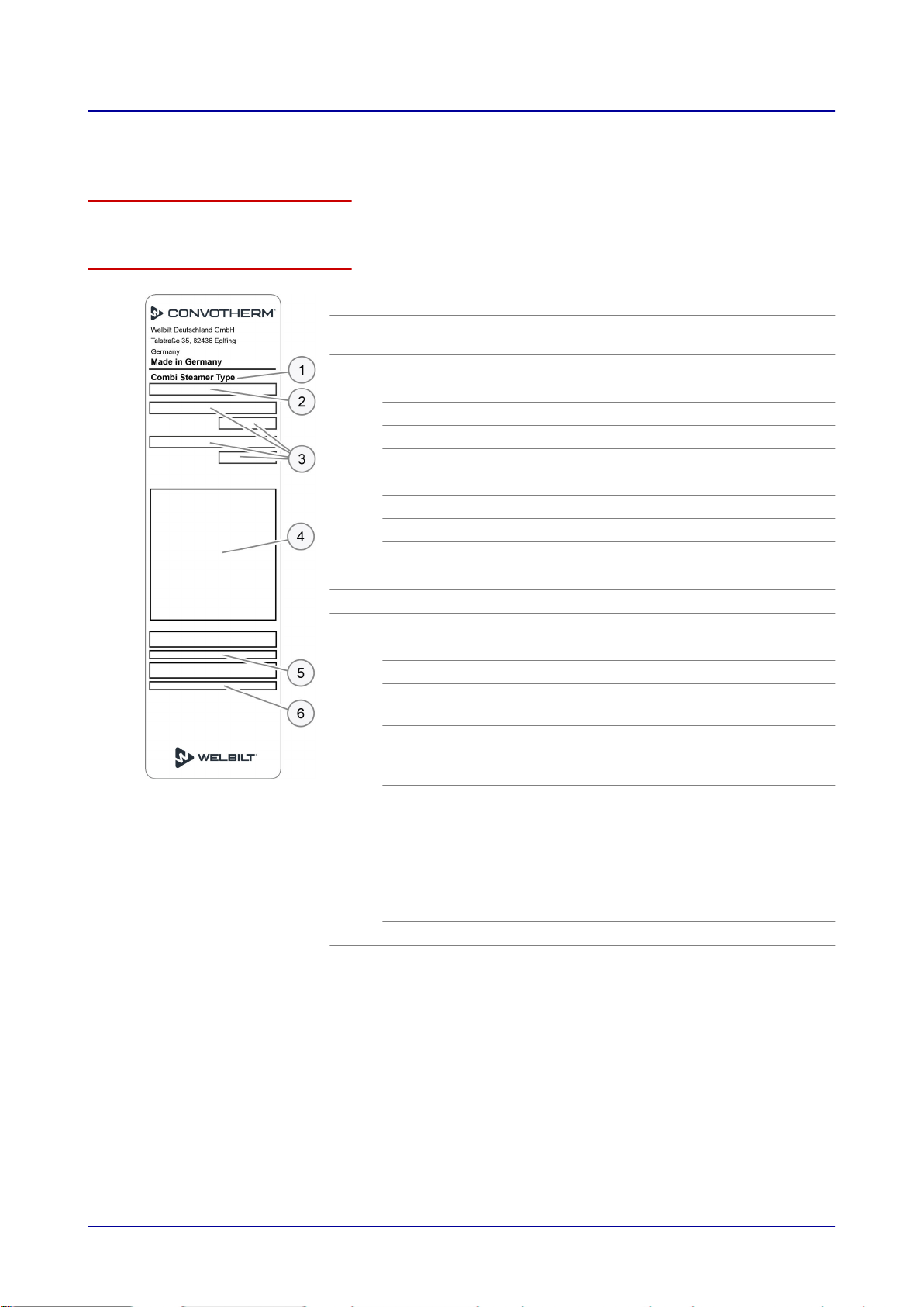
Nameplate location
The nameplate is found on the left side of the combi oven.
Nameplate layout and structure
No. Designation
1
2
3
4
5
6
Unit name
Combi Steamer
Trade name
Letters Meaning
C4 Convotherm 4 line of units
eT easyTouch controls
eD easyDial controls
xx.yy numbers Unit size
EB Electrical units with boiler
ES Electrical units with water injection
-N On units with NSF certification
Electrical specifications
Marks
Serial number
Letters Meaning
Heating method Electrical unit (V)
Steam generation meth‐
od
Unit size
Year of manufacture
Month of manufacture
Consecutive number 4-digit
Item number
■
Sprayer (S)
■
Boiler (B)
■
12.20 (5)
■
20.10 (6)
■
20.20 (7)
■
2021 (21)
■
2022 (22)
■
...
■
January (01)
■
February (02)
■
March (03)
■
...
Installation Manual 8
Page 9
1 General
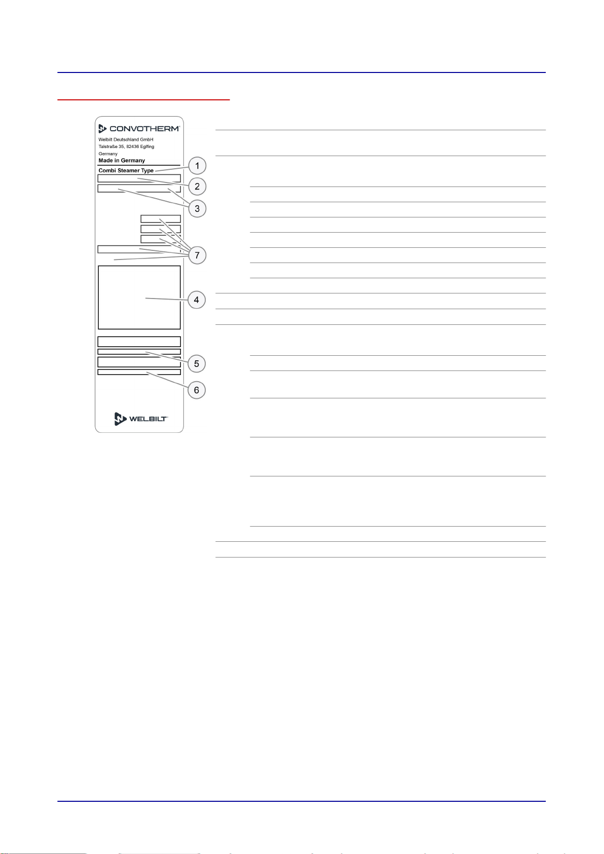
Nameplate layout and structure
No. Designation
1
Unit name
Combi Steamer
2
Trade name
Letters Meaning
C4 Convotherm 4 line of units
eT easyTouch controls
eD easyDial controls
xx.yy numbers Unit size
GB Gas unit with boiler
GS Gas unit with water injection
-N On units with NSF certification
3
4
5
Electrical specifications
Marks
Serial number
Letters Meaning
Heating method Gas unit (W)
Steam generation meth‐
od
Unit size
Year of manufacture
Month of manufacture
Consecutive number 4-digit
6
7
Item number
Gas specifications
■
Sprayer (S)
■
Boiler (B)
■
12.20 (5)
■
20.10 (6)
■
20.20 (7)
■
2021 (21)
■
2022 (22)
■
...
■
January (01)
■
February (02)
■
March (03)
■
...
Installation Manual 9
Page 10

1 General
1.3 Customer Documentation Structure
Unit documentation parts
Document type Contents
Installation manual
Operating manual
Operating instructions
Documentation for accessories
For information on how to install accessories (e.g., recoil hand shower, hood, stand on casters, stack‐
ing kit), please refer to the corresponding instructions for accessories.
■
Describes how to transport, set up, install, and put the unit into opera‐
tion
■
Goes over all the hazards involved in the various installation activities
and how to prevent and/or counter them
■
Contains technical specifications
■
Describes the work sequences and operating steps when cooking and
cleaning
■
Includes the maintenance schedule and troubleshooting information
■
Goes over all the hazards involved when operating the unit and how to
prevent and/or counter them
■
Describes the unit’s user interface
■
Includes the instructions for using the software
1.4
About This Installation Manual
Target groups
Name of target group Tasks
Person placing the unit
into operation
■
Responsible overall for placing the combi oven into operation
■
Briefing the user
(service technician)
Store manager
Person authorized to
give orders in the kitch‐
en area
■
Briefed on all of the combi oven's safety-relevant functions, mecha‐
nisms, and devices by the person placing the unit into operation
■
Shown how the unit is operated by the person placing the unit into oper‐
ation
■
If necessary, helping out as directed with transportation within the facili‐
ties and with setting up the unit
Mover Transporting the unit within the facilities
Service technician
Electrician
Water and wastewater
installer
■
Setting up the unit
■
Installing the fully automatic oven cleaning system
■
Placing the unit into operation and removing it from service
■
Connecting the unit to the electrical connection at the facilities
■
Uninstalling electrical connections
■
Connecting the unit to the water connection at the facilities
■
Uninstalling water connections
■
Connecting the unit to the drain connection at the facilities
■
Uninstalling the drain connection
Gas technician Installing and uninstalling gas connections
Decimal mark used
In order to ensure that all numbers can be properly understood internationally, a decimal point is al‐
ways used.
Installation Manual 10
Page 11
1 General
1.5 Safety Information That Must Be Read without Exception
Safety information found in the documentation for the customer
Only the installation manual and operating manual provide safety information for the combi oven.
The installation manual provides safety information for the transportation, setup, installation, placinginto-operation, and removal-from-service tasks it describes.
The operating manual provides safety information for the cooking, cleaning, and maintenance tasks it
describes.
When using the operating instructions, the operating manual or installation manual should always be
consulted in order to obtain the relevant safety information. When performing activities that go beyond
simply using the software, the safety information in the operating manual and installation manual must
always be observed.
Parts of this document that must be read without exception
Failure to take the information in this document into account may result in death, injury, or property
damage.
In order to ensure their safety and the safety of others, everyone working with/on the combi oven must
read and understand the following parts of this document before starting any work:
■
The
'For Your Safety' on page 17 section
■
The sections describing the work that will be carried out
Danger symbol
Danger symbol Meaning
Used to warn of potential injury. Observe all the precautionary state‐
ments following this symbol in order to avoid injury or death.
Precautionary statements
The precautionary statements in this manual are categorized using the following hazard levels:
Hazard level Consequences Likelihood
Death / severe injury (irreversible) Imminent
Death / severe injury (irreversible) Potential
Minor injury (reversible) Potential
NOTICE Property damage Potential
Installation Manual 11
Page 12
2 Configuration and Functions
2 Configuration and Functions
2.1 The Combi Oven's Configuration and Functions
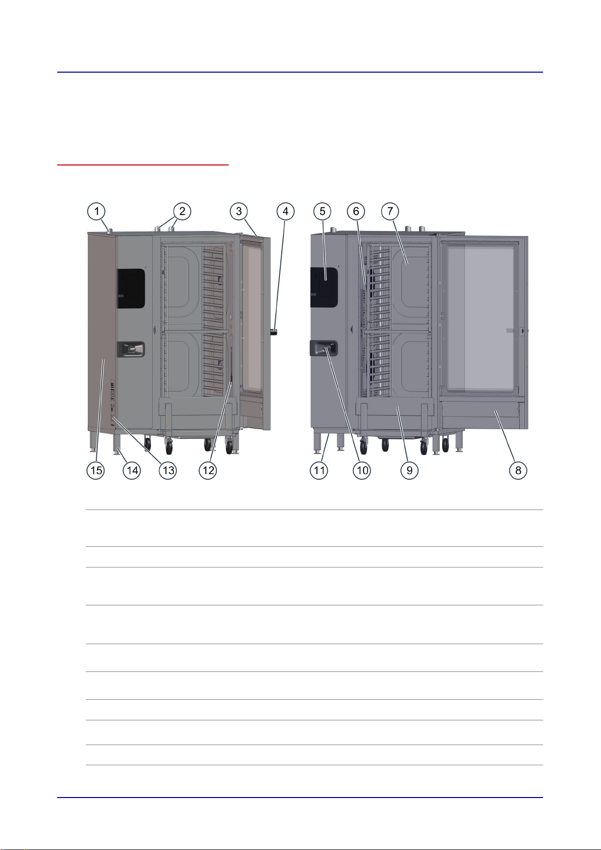
Parts and functions (electrical units)
The figure below shows a size 20.20 combi oven used as an example representing all electrical mod‐
els:
No. Designation Function
Ventilation port
1
■
Draws in ambient air in order to remove moisture from the oven
cavity
■
Compensates for pressure fluctuations inside the oven cavity
Air vent Lets hot steam escape
2
3
Unit door
■
Seals the oven cavity
■
When opened, it can be slid backwards along the unit's side in
order to save space ("disappearing door") (optional)
Door handle
4
Control panel
5
Suction panel
6
Oven cavity Is where food is placed while it is being cooked
7
Integrated preheat bridge
8
in unit door
Loading trolley Used to hold standard-size bakeware
9
■
Used to open and close the unit door
■
Cracked-open position for safely opening the unit
■
Antibacterial material with silver ions ("HygieniCare")
■
Used to operate the unit
■
Antibacterial ("HygieniCare")
■
Used to distribute heat uniformly within the oven cavity
■
Separates the fan compartment from the oven cavity
Works as a safety element during pre-heating and reduces ener‐
gy losses
Installation Manual 12
Page 13
2 Configuration and Functions
No. Designation Function
Recoil hand shower
10
(not included in certain
units)
Vents at the bottom of the
11
unit
Core temperature probe,
12
sous vide probe (optional)
■
Meant exclusively for rinsing the oven cavity with water
■
Is retracted automatically into its holder after being used
■
Antibacterial ("HygieniCare")
■
Used to ventilate the unit
■
Must not be blocked
■
Used to measure the food's internal temperature
■
Available as an internal version that is permanently connected
inside the oven and/or as an external version that can be tem‐
porarily connected
Nameplate Used to identify the unit
13
Unit feet Are height-adjustable so as to make it possible to level the unit
14
Side panel Covers the unit's wiring compartment
15
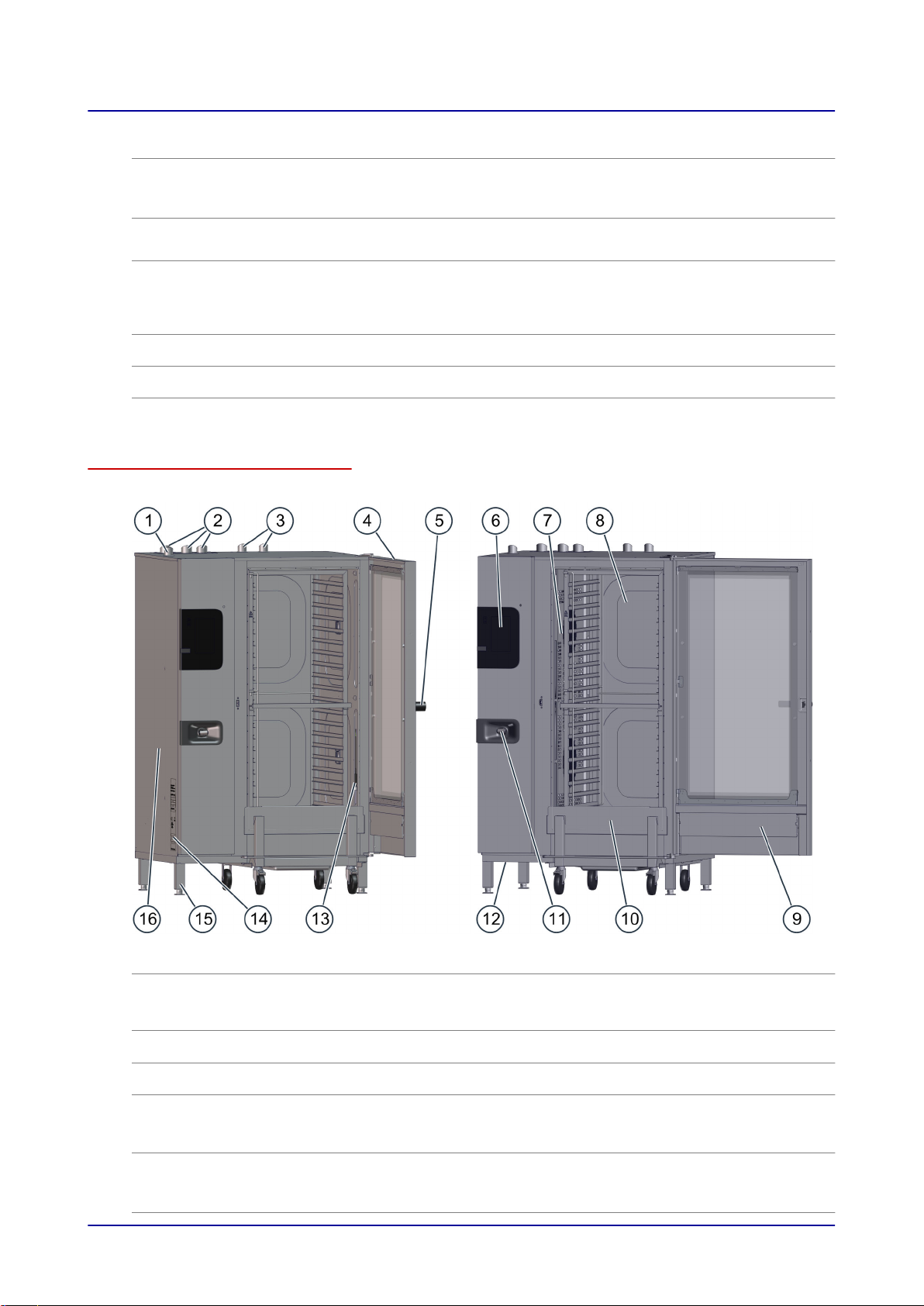
Parts and functions (gas units)
The figure below shows a size 20.20 combi oven used as an example representing all gas models:
No. Designation Function
Ventilation port
1
■
Draws in ambient air in order to remove moisture from the oven
cavity
■
Compensates for pressure fluctuations inside the oven cavity
Exhaust outlet Discharges hot exhaust gases
2
Air vent Lets hot steam escape
3
4
Unit door
■
Seals the oven cavity
■
When opened, it can be slid backwards along the unit's side in
order to save space ("disappearing door") (optional)
5
Door handle
■
Used to open and close the unit door
■
Cracked-open position for safely opening the unit
■
Antibacterial material with silver ions ("HygieniCare")
Installation Manual 13
Page 14
2 Configuration and Functions
No. Designation Function
Control panel
6
Suction panel
7
Oven cavity Is where food is placed while it is being cooked
8
■
Used to operate the unit
■
Antibacterial ("HygieniCare")
■
Used to distribute heat uniformly within the oven cavity
■
Separates the fan compartment from the oven cavity
Integrated preheat bridge
9
in unit door
Loading trolley Used to hold standard-size bakeware
10
Recoil hand shower
11
(not included in certain
units)
Vents at the bottom of the
12
unit
Core temperature probe,
13
sous vide probe (optional)
Works as a safety element during pre-heating and reduces ener‐
gy losses
■
Meant exclusively for rinsing the oven cavity with water
■
Is retracted automatically into its holder after being used
■
Antibacterial ("HygieniCare")
■
Used to ventilate the unit
■
Must not be blocked
■
Used to measure the food's internal temperature
■
Available as an internal version that is permanently connected
inside the oven and/or as an external version that can be tem‐
porarily connected
Nameplate Used to identify the unit
14
Unit feet Are height-adjustable so as to make it possible to level the unit
15
Side panel Covers the unit's wiring compartment
16
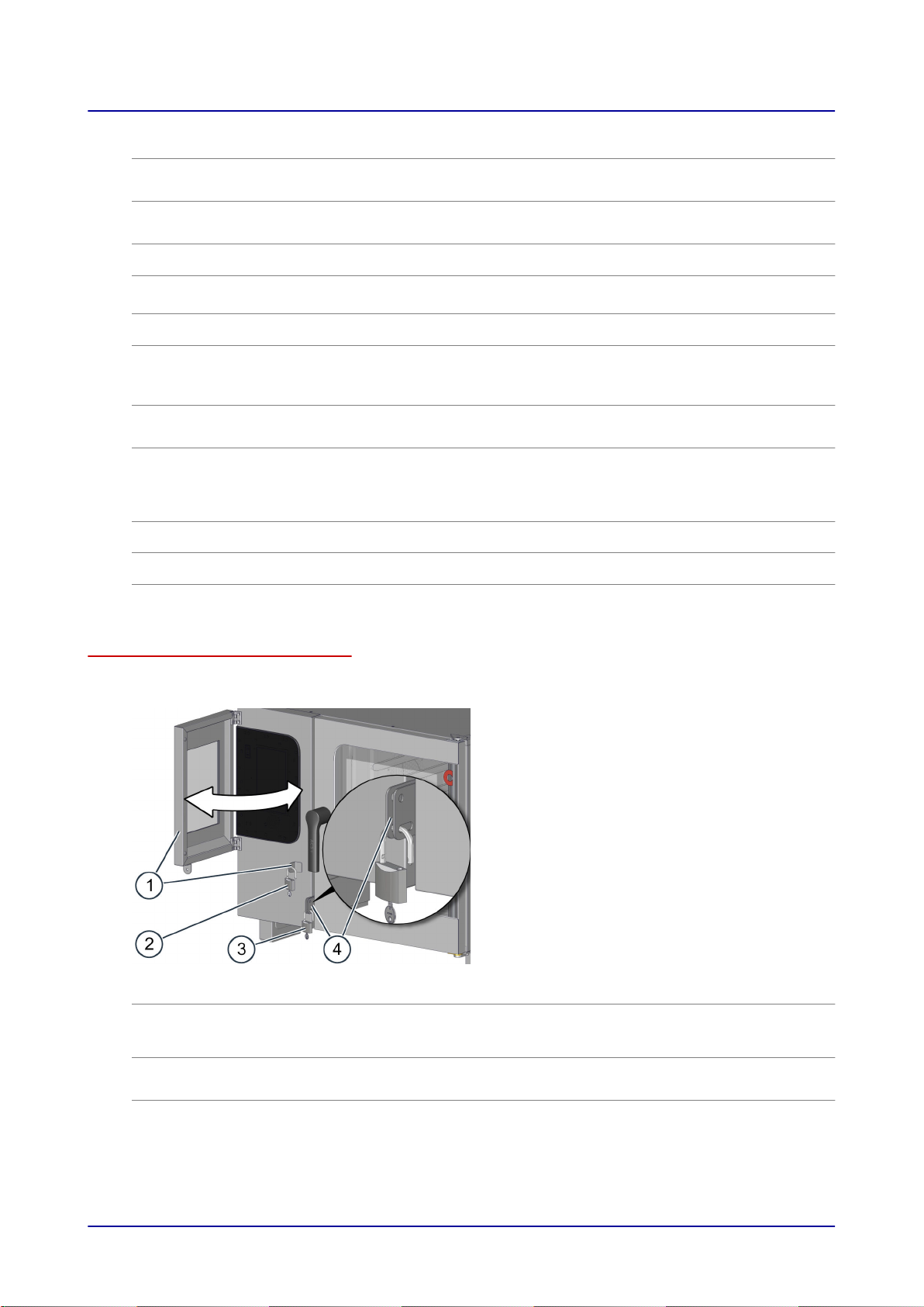
Parts and functions for special locking feature (security model only)
The figure below shows a special locking feature for enhanced security on a size 6.10 combi oven
used as an example representing all unit sizes:
No. Designation Function
Lockable operating panel
1
cover
The cover can be swung in and secured onto the unit case so
that it covers the operating panel, preventing unauthorized users
from operating the combi oven.
Padlock
2
■
Used to secure the operating panel cover onto the unit case
■
Not included
Installation Manual 14
Page 15

2 Configuration and Functions
No. Designation Function
Padlock
3
Unit door hasp Features two different slots that can be used to lock the unit door
4
■
Used to secure the unit door onto the unit case
■
Not included
in order to prevent unauthorized users from opening and closing
it
Unit door action:
■
If the unit door is locked using the upper slot, the door will al‐
ways be fully closed.
■
If the unit door is locked using the lower slot, it will be possible
to open the door to its cracked-open position
Material
The unit's inner and outer parts are made of stainless steel.
Installation Manual 15
Page 16
2 Configuration and Functions
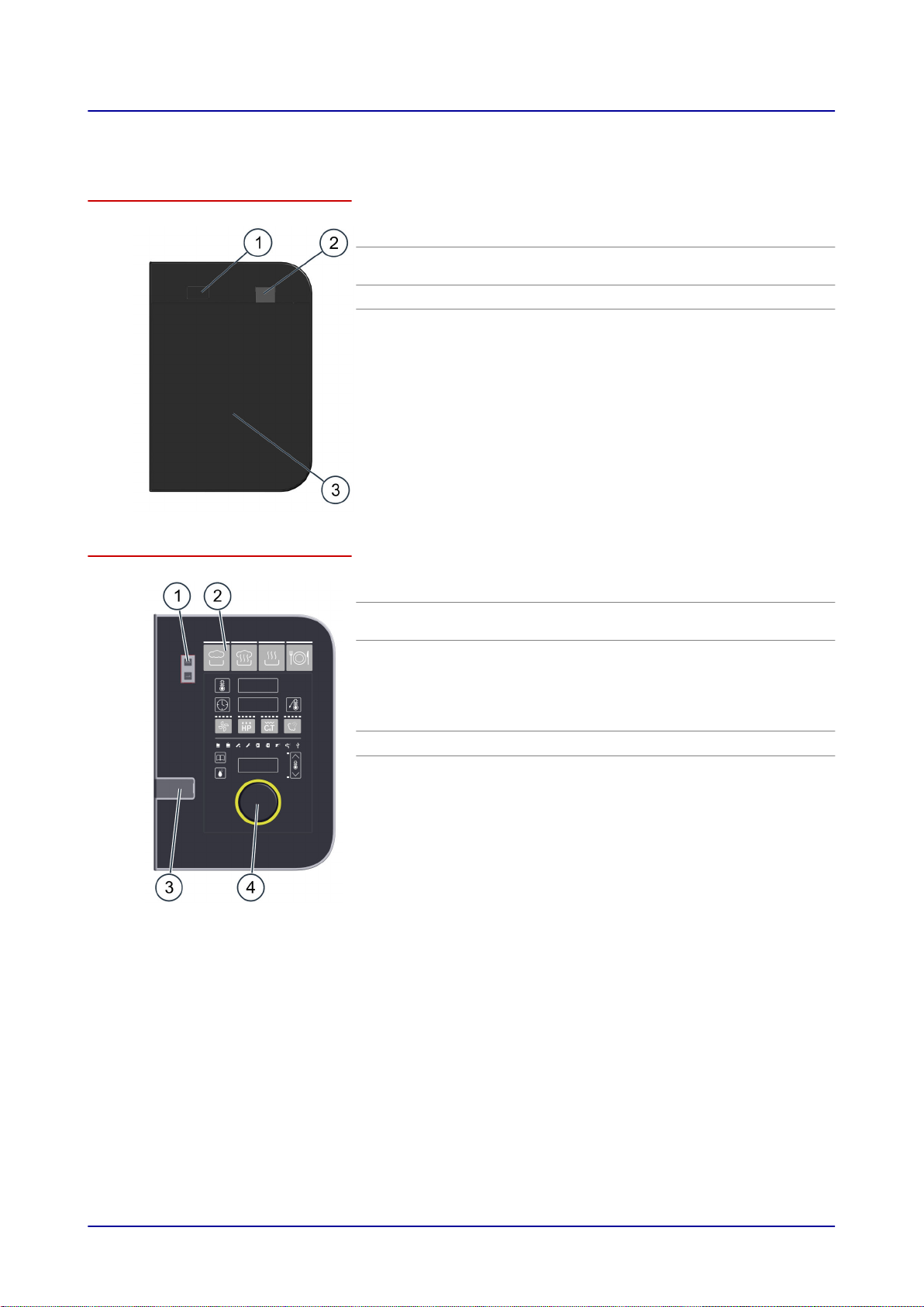
2.2 Operating Panel Layout and Functions
Control panel layout and parts in easyTouch
No. Designation Function
1
2
3
Unit
ON/OFF switch
USB port Used to plug in a USB stick
Full-touch dis‐
play
Used to turn the combi oven on and off
The unit's central control interface
■
Used by touching the icons on the fulltouch display
■
Status indicators
Operating panel layout and parts in easyDial
No. Designation Function
1
2
3
4
Unit
Used to turn the combi oven on and off
ON/OFF switch
Control panel The unit's central control interface
■
Buttons used to enter cooking programs
■
Displays used to indicate configured
values
■
Prompt indicators for the operator
USB port Used to plug in a USB stick
C-Dial Used to set cooking parameters by turn‐
ing and pressing the encoder.
Installation Manual 16
Page 17

3 For Your Safety
3 For Your Safety
Purpose of this section
The purpose of this section is to provide you with all the information you will need in order to safely
work with/on the combi oven without putting yourself and others at risk.
Read this section very carefully!
3.1
Basic Safety Instructions
Purpose of these instructions
The purpose of these instructions is to ensure that everyone working with and on the combi oven will
be fully aware of all the risks, hazards, and safety requirements involved and will observe the warnings
in the operating manual and on the combi oven. Failure to follow these instructions may result in
death, injury, or property damage.
Customer documentation manuals
Follow the instructions below:
■
Fully read the 'For Your Safety' section, as well as the section that applies to the way you will be
interacting with the combi oven.
■
Keep the customer documentation manuals handy at all times so that you can look up any required
information.
■
If you transfer the combi oven to a new owner, make sure to give the new owner the customer doc‐
umentation manuals as well.
Basic rules for installation
The unit must be installed in compliance with all national and state laws and regulations, with all appli‐
cable local requirements and regulations set forth by the relevant local utility companies and authori‐
ties, and with all other relevant regulations and standards.
These include, but are not limited to:
■
The National Electrical Code, ANSI/NFPA 70 (current edition)
■
The Canadian Electrical Code, CSA C22.2
■
National Fuel Gas Code, ANSI Z223.1 /NFPA 54 (latest version)
■
Natural Gas and Propane Installation Code, CSA B149.1
■
The Food Code and Food Service Sanitation Manual published by the Food and Drug Administra‐
tion (FDA) (current editions)
■
Latest edition of the International Plumbing Code published by the International Code Council (ICC)
or the Uniform Plumbing Code published by the International Association of Plumbing and Mechan‐
ical Officials (IAPMO)
■
The standards published by the National Sanitation Foundation (NSF)
■
All local fire protection and occupational health and safety regulations
Working with/on the combi oven
Follow the instructions below:
■
Only people who meet all the requirements specified in this operating manual should be allowed to
use and otherwise work with/on the combi oven.
■
Only use the combi oven for its intended use as described in this manual. Never, under any circum‐
stance, use the combi oven for other purposes, even if they seem obvious.
■
Observe all the safety measures specified in this operating manual and on the combi oven. This
applies especially to wearing the required personal protective equipment.
■
Make sure to always stay in the specified work areas when working with/on the combi oven.
■
Do not make any alterations to the combi oven. This includes removing components and adding
components that have not been expressly approved.
any safety devices or guards.
Installation Manual 17
Above all, however, make sure not to disable
Page 18

3 For Your Safety
For more information...
Related subjects
Your Combi Oven's Intended Use 19
Warning Labels on the Combi Oven 21
Hazards posed by the unit 23
Safety Devices 26
Staff and Work Area Requirements 28
Personal protective equipment 30
Installation Manual 18
Page 19

3 For Your Safety
3.2 Your Combi Oven's Intended Use
Intended use
■
The combi oven has been designed and built exclusively for cooking a variety of food in GN con‐
tainers (e.g., Gastronorm containers, patisserie-size sheet pans).
steam (steam superheated without pressure) are used for this purpose.
■
The food containers can be made of stainless steel, ceramic, plastic, aluminum, enameled steel, or
glass. Glass food containers must not be damaged.
■
The combi oven is intended exclusively for professional commercial use.
Limitations on use
The combi oven should not be used to heat up the following materials:
■
Dry powders or granular products
■
Readily flammable substances or objects with a flashpoint lower than 518
mable oils, fats, plastics, cleaning agents, and liquids containing alcohol.
■
Food in sealed cans
Staff requirements
■
The combi oven must be run and installed exclusively by staff meeting the specified requirements.
For the corresponding training and qualifications requirements, please refer to
Requirements' on page 28.
■
All staff must be familiar with the risks, hazards, and rules involved in handling heavy loads.
Steam, convection, and combi-
°F, such as readily flam‐
'Staff and Work Area
Requirements concerning the combi oven's functional capability
■
The combi oven should only be used if all safety devices and guards are present, working properly,
and correctly locked in place.
■
All manufacturer specifications concerning how to run and service the combi oven must be ob‐
served.
■
The load placed inside the combi oven must never exceed the maximum permissible loading
weight; please refer to
'Technical Data' on page 76.
Requirements concerning the combi oven's surroundings
Required combi oven surroundings
■
Ambient temperature between 40°F and 95°F
■
No toxic or potentially explosive atmospheres
■
Do not use or store gasoline or other flammable vapors, gases, or liquids in the vicinity of a combi
oven
■
Dry kitchen floor in order to reduce the risk of accidents occurring
Required installation location characteristics
■
NO fire alarms or sprinkler system directly above the unit
■
NO flammable materials, gases, or liquids above, on, under, or close to the unit
Limitations on use
■
When used outdoors, the unit must be protected from rain and wind
■
Do NOT shift or move the unit during operation
Installation Manual 19
Page 20

3 For Your Safety
Prerequisites for cleaning
■
Only use the cleaning agents approved by the manufacturer.
■
Only use the cleaning tools specified by the manufacturer; please refer to 'Cleaning schedule' in
the operating manual.
■
Do NOT use a pressure washer to clean the unit.
■
Do NOT use a water jet to clean the outside of the unit. Do not use the recoil hand shower or an
external water jet for anything other than cleaning the oven cavity.
■
Do NOT use bases or acids to clean the combi oven and make sure it is not exposed to acid
fumes. The only exception is when the oven cavity is descaled by an authorized service company
following the manufacturer's instructions.
Installation Manual 20
Page 21
3 For Your Safety
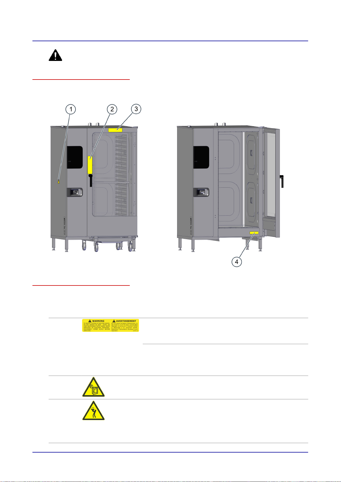
3.3 Warning Labels on the Combi Oven
Warning label locations on the unit
The figure below shows a size 20.20 electrical combi oven used as an example representing all floorstanding models:
Required warning labels on the unit
The following warning labels must always be clearly visible on the combi oven at the locations shown
in the previous figure.
Location Warning label Description
1 and 4
2
2
WARNING
To reduce the risk of electric shock, do not remove or open
cover. No user serviceable parts inside. Refer servicing to
qualified personnel. Disconnect power supply before servicing.
AVERTISSEMENT
Afin de réduire le risque d'électrocution, ne pas retirer ou ouvrir
le capot. Aucune pièce réparable ne se trouve à l'intérieur.
Confier le dépannage à du personnel qualifié. Débrancher l'ali‐
mentation électrique avant réparation.
Hot steam warning
There is a risk of scalding posed by the hot steam coming out
when the unit door is opened.
Standard model
Hot liquid warning
Risk of scalding when liquid food is spilled. This hazard exists
when liquids, or food that becomes liquefied during cooking,
are placed on the upper shelf levels. Do not use shelf levels lo‐
cated above your field of view to hold liquids or food that will
become liquefied.
Installation Manual 21
Page 22
3 For Your Safety
Location Warning label Description
2
3
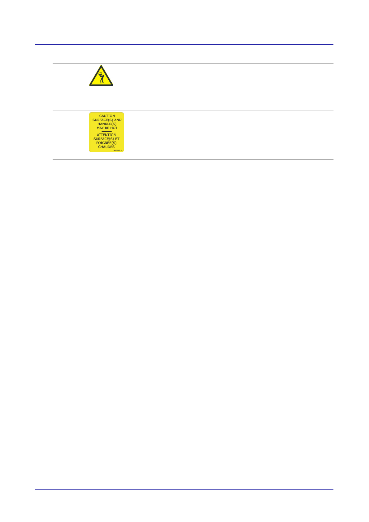
Bakery model
Hazard posed by hot food and hot bakeware
Hot food and hot bakeware will pose a burn hazard if the bake‐
ware falls off the shelf levels or if food slides off bakeware that
is being held in an inclined position. This hazard will be particu‐
larly acute in the case of shelf levels located above the opera‐
tor's field of view.
CAUTION
Surface(s) and Handle(s) may be hot.
ATTENTION
Surface(s) et poignée(s) chaudes
Installation Manual 22
Page 23
3 For Your Safety
3.4 Hazards posed by the unit
General rules when using the unit
The combi oven has been designed in such a way as to ensure that users will be protected from all
hazards that can be reasonably prevented using design-based measures.
However, the combi oven's intended use entails a series of residual risks that will require you to take
precautions in order to avoid them. The safety devices and guards on the unit may protect you from
some of these risks to a certain extent. However, in order for the safety devices and guards to protect
you, you must always make sure that they are in place and working properly.
Following is a description of these residual risks and what kinds of hazards they pose.
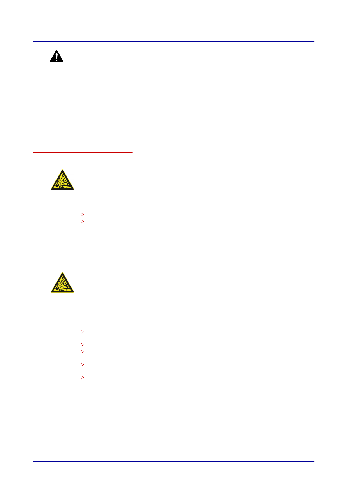
Leaking gas during placement into operation
Leaking gas can result in the following hazards during placement into operation:
Gas explosion hazard
When?
■
Whenever the unit is moved and this causes leaks in connections
■
Whenever the gas line is damaged
How can I avoid the hazard?
Do not move the unit during operation or cleaning
If you smell gas, take the appropriate steps; please refer to 'What to do if you smell gas'
on page
70
Gas leaks during installation and placement into operation
Leaking gas can result in the following hazards as a result of the unit being improperly installed and
removed from service:
Gas explosion hazard
When?
■
Whenever there are leaks in gas lines
■
Whenever the building's gas valve is opened before the connection is ready
■
Whenever the gas is not shut off before starting work on gas units and/or gas installa‐
tions for removal from service
How can I avoid the hazard?
Make sure to only have certified gas installation engineers from an authorized service
company work on the gas system
Install a gas shut-off device close to the unit
Always check all the connection points on components conveying gas for leaks after
connecting the gas system and after performing any work on these components.
Before placing the combi oven into operation, make sure that none of the specified
connection points outside or inside the unit have any leaks.
Shut off the gas before starting any removal-from-service work on gas units and/or gas
system components
Installation Manual 23
Page 24
3 For Your Safety
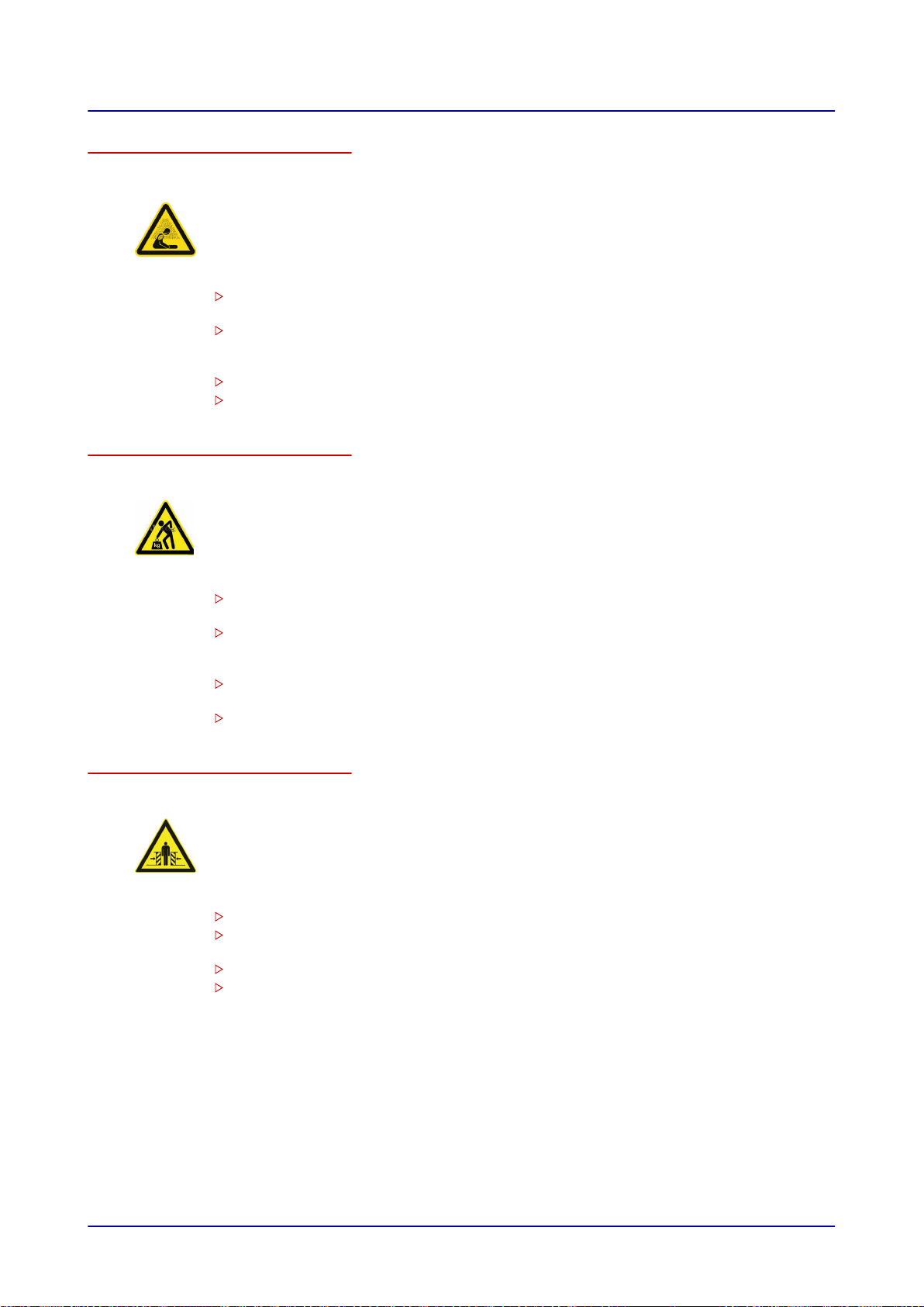
Lack of oxygen
Gas units can result in the following hazards in the kitchen:
Suffocation hazard due to lack of oxygen
Where?
■
At the unit's installation location
How can I avoid the hazard?
Check the exhaust gas readings and have a certified gas installation engineer from an
authorized service company adjust the burner if necessary
Make sure that there is a ventilation system that is fully functional and running. In
addition, make sure to follow all the ventilation rules and practices specified by the gas
installation engineer
Do not block or otherwise obstruct the area below the unit
Operate the unit in windless environments only
Moving heavy loads
During transportation and setup, the following hazards can be posed when moving heavy loads:
Risk of injury due to excessive exertion
When?
■
Whenever moving or lifting the unit
How can I avoid the hazard?
Use a forklift or pallet jack to place the unit at its installation location or to change its
position or location
Make sure that a sufficient number of people help correct the unit's position; do not lift or
carry too much weight during the process (guideline: 33lbs to a maximum of 121
depending on age and gender).
Comply with all occupational health and safety regulations that apply at the installation
location
Wear the required personal protective equipment
lbs
Loss of unit stability
During transportation and setup, the following hazards can be posed when moving the unit:
Crush hazard for all body parts if the unit falls down
When?
■
Whenever moving or lifting the unit
How can I avoid the hazard?
Use appropriate transportation equipment
Transport equipment slowly and carefully and secure it in such a way that it cannot tip
over
Keep the unit's center of gravity in mind
Avoid bumping into objects
Installation Manual 24
Page 25
3 For Your Safety
Live parts
The unit can pose the following hazards during all installation work:
Risk of electric shock posed by live parts
Where?
■
Under covers
■
Under the operating panel
■
On the power cable
How can I avoid the hazard?
De-energize all connections
Lock out and tag out all switches
Wait 15 minutes so that the DC bus capacitors can discharge fully
Make sure that all electrical connections are undamaged and properly connected
Make sure that all legally required safety checks have been carried out.
Missing equipotential bonding
The unit can pose the following hazards during all installation work:
Risk of electric shock posed by live parts
Where?
■
On the unit and on neighboring metal parts
■
On the unit and on neighboring metal accessories
How can I avoid the hazard?
Before putting the unit into operation, make sure that it is bonded to an electrical ground
system together with all metal accessories
Contact with cleaning agents
The unit can pose the following hazards during all installation work:
Skin, eye, and respiratory tract irritation hazard as a result of contact with cleaning agents
and their vapors
When?
■
When installing the cleaning system
■
Whenever handling cleaning agent containers
■
Whenever using aggressive cleaning agents
How can I avoid the hazard?
Wear the required personal protective equipment
Observe the instructions and warnings on the cleaning agent labels and in the relevant
safety data sheets
Use specified cleaning agents only
General hazards
In addition to the specified hazards, keep in mind all the general hazards that are found in kitchen en‐
vironments. For more information, please refer to the 'For Your Safety' in the operating manual.
Installation Manual 25
Page 26
3 For Your Safety
3.5 Safety Devices
Meaning
The combi oven features a series of safety devices and guards that protect the user from a variety of
hazards. All safety devices and guards must be present, fully functional, and locked properly without
exception when the combi oven is being used.
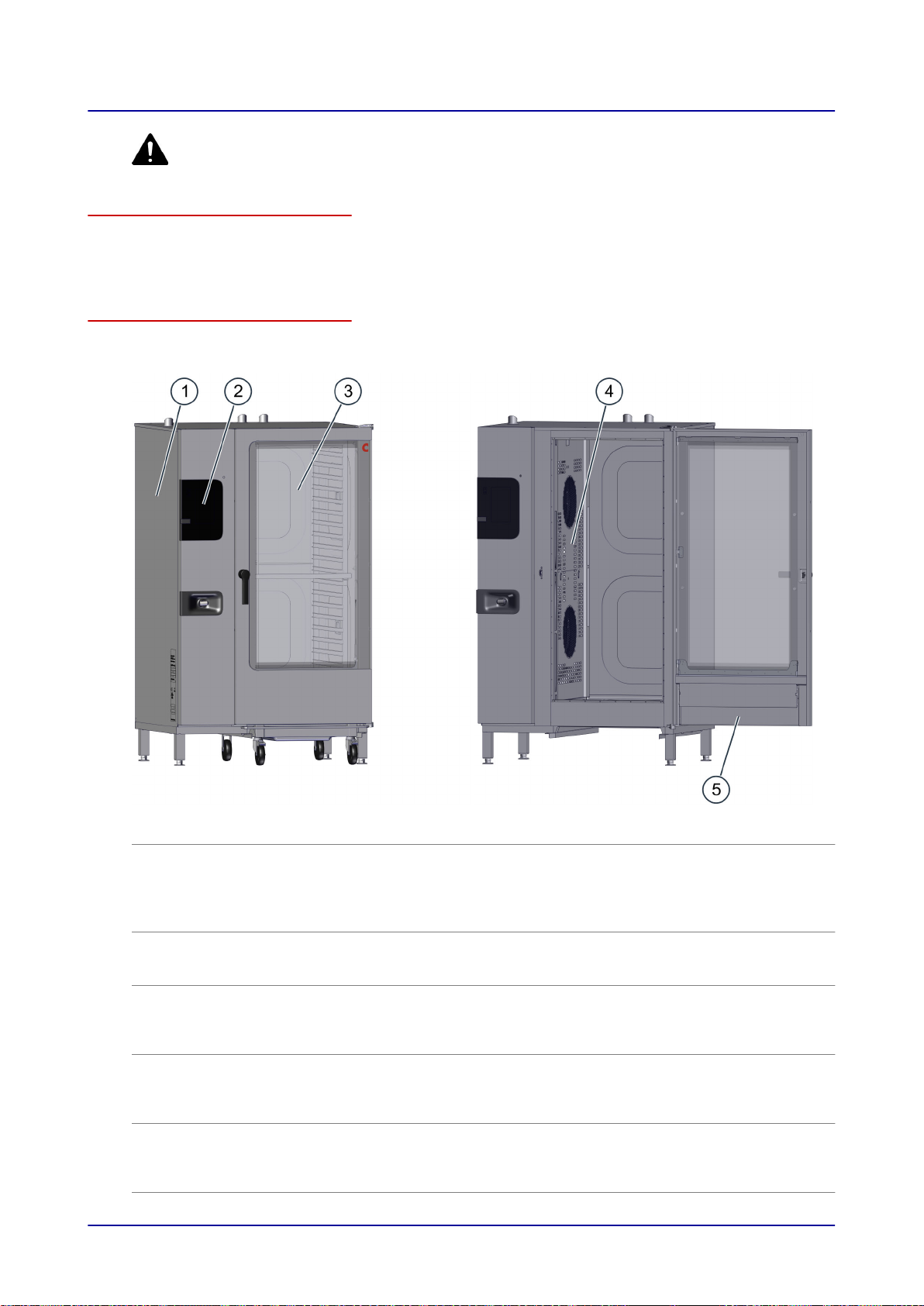
Location and functions
The figure below shows a size 20.20 electrical combi oven used as an example representing all floorstanding models:
No. Guard or safety device Function Check
1
Cover; can only be re‐
moved with tools
■
Prevents staff from acciden‐
tally touching live parts
■
Prevents staff from reaching
into the moving fan(s) inside
the wiring compartment
2
Operating panel; can
only be removed with
Prevents staff from acciden‐
tally touching live parts
tools
3
Unit door Protects the operator and the
surroundings from hot steam
4
Suction panel inside
the oven cavity; can
only be removed with
Prevents staff from reaching
into the moving fan(s) and en‐
sures proper heat distribution
tools
5
Integrated preheat
bridge in unit door
Prevents scalding caused by
escaping steam if the loading
trolley is not inside the unit
during pre-heating
Installation Manual 26
Check to make sure that the
cover is in its proper place
Check to make sure that the
operating panel is in its proper
place
Check the pane for scratches,
cracks, and other damage on
a regular basis and replace it
if you detect any damage
Please refer to 'Releasing the
Suction Panel and Locking it
Back in Place' in the operating
manual
None
Page 27

3 For Your Safety
No. Guard or safety device Function Check
6
(not shown)
7
(installed by
the
customer)
8
(installed by
the
customer)
Safety thermostat
■
Boiler
■
Oven cavity
Disconnector
Gas shut-off device
Turns off the unit if the tem‐
perature exceeds the allowa‐
ble limit
■
Installed close to the unit by
the customer. Easily visible
and accessible, 3-pole, with
a contact gap of at least
0.12".
■
Used to de-energize the
unit during cleaning, re‐
pairs, and maintenance
work, as well as in hazard‐
ous situations
■
Installed close to the unit by
the customer; easily acces‐
sible and clearly marked
■
Used to disconnect the unit
from the gas supply during
cleaning, repair, and main‐
tenance work, as well as in
hazardous situations.
An error code will be output in
the event of a fault
(Contact a service company
that is authorized to reset the
safety thermostat)
Procedure:
■
Trip the disconnector
■
Check that all three phases
are de-energized at the
unit's -X10 terminal block
Procedure:
■
Close the gas shut-off de‐
vice
■
Make sure that the gas flow
to the unit has been shut off
Safety measures
The following measures will contribute to greater safety:
Measure Function Check
Unit door solenoid
switch (electrical door
sensor)
■
Stops/turns off the following when
the unit door is opened:
■
Fan (will stop after a few sec‐
onds)
■
Heating element
■
Cleaning agent spraying in the
fully automatic oven cleaning
process
■
Prompts the user to close the unit
door
Resuming after a power
outage if there was
cleaning agent inside
■
Starts the fully automatic oven
cleaning process again, from a de‐
fined state, after a power outage
the unit when the power
went out
Test the door solenoid switch with
the combi oven at a low temperature
Procedure:
■
Fully open the unit door
■
Press Start
Result:
The motor must not start running.
None
Installation Manual 27
Page 28

3 For Your Safety
3.6 Staff and Work Area Requirements
Staff requirements
The table below specifies the qualifications needed for each role. Provided that they have the required
qualifications, a single person can take over more than one role if necessary.
Role Required qualifications Tasks
The person re‐
sponsible for the
Is familiar with the rules involved in han‐
dling heavy loads
combi oven
Mover
■
Trained in the use of forklifts and/or
pallet jacks
■
Is familiar with the rules involved in
handling heavy loads
Service technician■Qualified staff from an authorized
service company
■
Has relevant technical training
■
Has unit-specific training
■
Is familiar with the rules involved in
handling heavy loads
■
Is able to assess whether the unit's
power, water, drain, and network con‐
nections have been correctly set up.
Gas technician
■
Is a technician authorized by the gas
provider
■
Has relevant training
■
Qualified staff from an authorized
service company
Electrician
■
Qualified staff from an authorized
service company
■
Has relevant training
■
Is a qualified electrician and is familiar
with the technical standards that must
be applied
■
Briefed on all of the combi oven's
safety-relevant functions, mecha‐
nisms, and devices by the person
placing the unit into operation so
that the information can be relayed
to all the staff operating the unit
■
Shown how the unit is operated by
the person placing the unit into op‐
eration so that the information can
be relayed to all the staff operating
the unit
■
If necessary, helping out as direc‐
ted with transportation within the
facilities and with setting up the
unit
Transporting the unit within the facili‐
ties
■
Setting up the unit
■
Installing the fully automatic oven
cleaning system
■
Placing the unit into operation
■
Removing the unit from service
■
Connecting the unit to the gas con‐
nection at the facilities
■
Uninstalling gas connections
■
Connecting the unit to the electri‐
cal connection at the facilities
■
Uninstalling electrical connections
Installation Manual 28
Page 29

3 For Your Safety
Role Required qualifications Tasks
Water and waste‐
water installer
■
Qualified staff from an authorized
service company
■
Has relevant training
■
Connecting the unit to the water
connection at the facilities
■
Uninstalling water connections
■
Connecting the unit to the drain
connection at the facilities
■
Uninstalling the drain connection
Person placing the
unit into operation
(service techni‐
cian)
■
Is an employee from an authorized
service company who is responsible
overall for placing the unit into opera‐
tion
■
Has relevant technical training
■
Has unit-specific training
■
Is familiar with the rules involved in
■
Briefing the company operating the
unit or the responsible employee
■
Checking all steps and conditions
as per the checklists
handling heavy loads
■
Is able to assess whether the unit's
power, water, and drain connections
have been correctly set up and is fa‐
miliar with the technical standards
that must be applied.
Work areas during installation and placement into operation
During installation and placement into operation, the work area for staff will be the entire area occu‐
pied by the unit and its surroundings.
Installation Manual 29
Page 30

3 For Your Safety
3.7 Personal protective equipment
Transportation and setup
Task Tools used Personal Protective Equipment
■
Transporting the unit within the fa‐
cilities
■
Setting up the unit at the installa‐
tion location
Installation, placing the unit into operation, and removing it from service
Task Tools used Personal Protective Equipment
Installing and uninstalling (removing
from service) the following:
■
Electrical connection
■
Water connection
■
Drain Connection
■
Gas connection
■
Automatic grease management
Installing and uninstalling the fully
automatic oven cleaning system
■
Placing the unit into operation
■
Briefing the user
Removing the unit (removing it from
service)
A forklift or pallet jack
Tools and equipment
necessary for the specif‐
ic task at hand
Tools and equipment
necessary for the specif‐
ic task at hand
Tools and equipment
necessary for the specif‐
ic task at hand
■
Carrying straps
■
Appropriate lifting
equipment
■
A forklift or pallet jack
■
Protective gloves
■
Safety footwear
■
A hard hat (e. g., when there are
suspended loads, doing overhead
work)
Work clothes and personal protec‐
tive equipment based on the re‐
quired task in accordance with
country-specific regulations
The protective equipment required
will depend on the cleaning agents
being used, and may include:
■
Respirator
■
Safety eyewear
■
Protective gloves
■
Protective clothing/apron
More detailed specifications regard‐
ing this equipment can be found in
the EC safety data sheets for the
cleaning agent(s) being used. For
the latest version of these data
sheets, please contact the manu‐
facturer.
Always follow the instructions and
observe all warnings found on the
labels used for the cleaning
agent(s).
Wear appropriate work clothes for
kitchen work as required by your
country-specific standards and reg‐
ulations, especially:
■
Protective clothing
■
Heat-resistant gloves
■
Safety footwear
■
Protective gloves
■
Safety footwear
■
A hard hat (e.
g., when there are
suspended loads, doing overhead
work)
Installation Manual 30
Page 31

4 Transportation
4 Transportation
4.1 Transporting the unit to the installation location
Required space during transportation
Make sure that the transportation route you will be following has enough space to accommodate the
unit's entire width and height at all times.
The following table lists the dimensions for the units together with their packaging. This list can be
used to figure out the required minimum door width and height required in order to be able to get the
unit to its intended installation location:
12.20 20.10 20.20
Width
Height
Depth
Load capacity for transportation
Make sure that the transportation equipment you will be using is able to handle the loads it will be
transporting.
To determine the minimum load capacity that the transportation equipment must have, check the unit’s
weight, including its packaging, in the
'Technical Data' on page 76 section.
[in] 56.3 46.7 56.3
[in] 65.2 85.0 85.0
[in] 46.9 39.0 46.9
Transporting the unit to the installation location for the first time
Observe the following when transporting the unit:
■
Always use a pallet to transport the unit.
■
Always keep the unit upright when moving it.
■
Use a pallet jack or forklift to lift the unit.
■
Transport the unit slowly and carefully and secure it in such a way that it cannot tip over.
Make sure not to bump into the unit.
Avoid uneven transportation routes and steep inclinations.
4.2 Preparing for Unpacking
Preparing for unpacking
Observe the following before unpacking the unit:
■
Check the outer packaging for damage.
■
Take the supplemental sheet with unpacking instructions from the shipping documents.
Installation Manual 31
Page 32

4 Transportation
4.3 Included equipment and parts
Unit and accessories
The unit scope consists of the following parts:
■
One combi oven
■
One loading trolley
■
Two G3/4" - 3/4" GHT adapters (ConvoClean only and preinstalled)
■
Two 3/4" water supply lines (ConvoClean only)
■
One 2" drain pipe rubber elbow (ConvoClean only)
■
One empty canister for pumped-out grease (grill version)
■
One connection tube with an attached screw closure for the grease collection canister One combi
oven (grill version)
Documents
The following documents are enclosed with the unit:
■
One installation manual
■
One operating manual (hardware)
■
One operating instructions document (software)
■
One supplemental sheet with unpacking instructions
■
One installation and placement-into-operation checklist
Installation Manual 32
Page 33

5 Setup
5 Setup
5.1 Adjacent Systems
Handling exhaust air
During operation, the combi oven will produce heat and moisture, most of which will escape upwards
into the ambient air in the form of hot steam coming through the air vent(s). Do not connect any lines
or ducts directly to the combi oven's air vent(s)!
The manufacturer recommends removing this exhaust air from the combi oven's working area with a
range hood or ventilated ceiling.
In order to prevent fire hazards and other structural issues, such as corrosion, mold, and/or a de‐
crease in stability, there must be sufficient clearance between the top of the unit and the ceiling. This
clearance must be determined by taking the following into account:
■
The reference point for the minimum vertical clearance (refer to 'Installation Location Require‐
ments' on page 34).
■
The type of exhaust system being used
■
The characteristics of the ceiling at the installation location
The combi oven must always be set up, installed, and operated in compliance with all applicable coun‐
try-specific and local standards and regulations.
Handling exhaust gas from gas units
Exhaust gas with a temperature of up to 930 °F will escape into the ambient air through the exhaust
outlet(s) at the top of the unit. Do not connect any lines or ducts directly to the combi oven's exhaust
outlet(s) in order to divert this exhaust gas!
It is absolutely mandatory to use a ventilation system with a safety shutdown function in order to evac‐
uate the exhaust gas.
In order to prevent fire hazards, there must not be any flammable materials above the unit, and there
must be sufficient clearance between the top of the unit and the ceiling. This clearance must be deter‐
mined by taking the following into account:
■
The reference point for the minimum vertical clearance, refer to
'Installation Location Requirements'
on page 34
■
The type of exhaust system and exhaust gas extraction system being used
■
The characteristics of the ceiling at the installation location
The combi oven must always be set up, installed, and operated in compliance with all applicable coun‐
try-specific and local standards and regulations.
Installation Manual 33
Page 34

5 Setup
5.2 Installation location requirements
Meaning
This section provides information on how to choose a suitable installation location for the unit. Careful‐
ly check the intended installation location to make sure it is adequate before bringing the unit there
and starting with the installation!
Setup standards and regulations
All national, state, and local standards and regulations concerning commercial kitchen operations
must be complied with. These include, but
and Drug Administration (FDA) (current edition) and the standards published by the National Sanita‐
tion Foundation (NSF).
The local rules and regulations that apply to the installation location, as defined by the relevant local
authorities and utility companies, must be complied with.
Rules for safely setting up the unit
In order to prevent hazards that may be posed by the installation location and by the unit's surround‐
ings, follow the rules below:
■
It must be possible to adhere to the operating conditions at all times. For these operating condi‐
tions, please refer to
■
The heat loss at hot surfaces poses a fire hazard. Accordingly, set up the unit in non-combustible
'Requirements concerning the combi oven's surroundings' on page 19.
environments only.
■
There must not be any flammable materials, gases, or liquids at a distance of less than 18" from
the sides of the unit (right, left, front, back) and 40" from the top of the unit. When choosing an in‐
stallation location, make sure to observe this requirement together with the requirements in the 'Ad‐
jacent Systems' on page 33 section and the unit's minimum space requirements without exception!
■
Substructures (tables, frames) and supporting surfaces (floors, bases, countertops) must be made
of non-combustible materials and must not be coated or covered with any flammable materials (no
fiberboard, no contact between flammable materials and the bottom of the unit). Likewise, there
must not be any flammable materials on the undersides of these structures. The unit supporting
surfaces on substructures of this type must project beyond the unit's base on all sides by 12" or
more.
■
The minimum distance from heat sources in the vicinity of the units is 20".
■
The minimum distance that must be maintained between the unit and any deep fryers or open ket‐
tle fryers in the vicinity is as follows 63''. The unit must be set up in such a way that liquids from the
unit and from cooking processes will not be able to get to deep fryers and open kettle fryers under
any circumstance.
■
Do not set up the unit directly under a fire alarm or sprinkler system. The sensitivity of fire alarms
and sprinkler systems must be adjusted in line with the amount of vapor and steam that the unit is
expected to produce.
■
The connection between the combi oven's drain pipe and the sewer system must be located out‐
side the perimeter of the unit's base area. Due to potential wastewater vapors, there must not be a
drain connection or open sewer line below the unit's base area.
■
It must be possible to set up the unit at the installation location in such a way that it will not topple
over or shift. All supporting surface requirements must be met.
■
With its current configuration, the unit is not designed to be used in environments where it could be
subjected to strong vibrations or mechanical shock (e.g., on vehicles or ships).
are not limited to, the Food Code published by the Food
Installation Manual 34
Page 35

5 Setup
Supporting surface requirements
The supporting surface must have the following characteristics:
■
The supporting surface must be flat and level.
■
The supporting surface must be capable of bearing the unit's weight.
The unit's weight will be made up of the following depending on its specific model and equipment:
■
The combi oven's empty weight
■
Maximum permissible loading weight
■
The maximum cleaning agent weight when the unit is equipped with a ConvoClean / ConvoClean+
system
Add the following individual weights to calculate the total unit weight:
12.20 20.10 20.20
Individual weights
The combi oven's empty weight [lbs] See the weight without
packaging in
Data' on page 76
Maximum permissible loading weight [lbs] 265 220 397
Maximum weight of cleaning agents [lbs] 44 44 44
Space required
'Technical
In order to ensure that the combi oven will be used safely – especially when it comes to safely han‐
dling hot food –, it is necessary to keep a lot more free space in front of the units than is specified in
the space requirements!
In order to determine the actual space required between the top of the combi oven and the ceiling,
please consult the
'Adjacent Systems' on page 33 section.
Generally speaking, it is recommended to maintain large clearances between the units and the walls
in order to make it easier for service staff to access the unit as needed.
Do not cover, obstruct, or block the following parts at the installation location (please refer to 'The
Combi Oven's Configuration and Functions' on page 12 as well):
■
The air vents and exhaust outlets at the top of the unit
■
The dry air intake at the top of the unit
■
The ventilation openings at the bottom of the unit
Installation Manual 35
Page 36
90°
S1 S3
B1
S2
T
180°
B2
S3
5 Setup
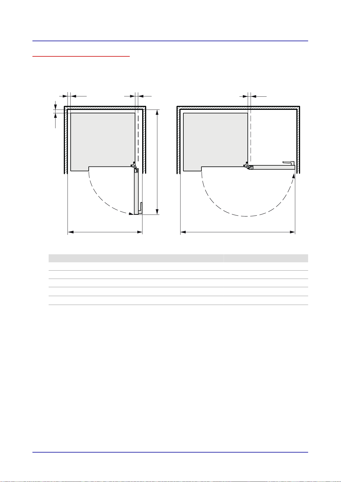
Required space for units with a right-hinged door – width and depth
The following diagrams, as well as the following table, show the space required by the unit for various
installation and operating situations, as well as the minimum horizontal clearances required relative to
adjacent walls and surfaces. The safety clearances on the left, right, and rear must be maintained
without exception.
Meaning
B1 Required width when the unit door is open 90° [in] 52 42 52
B2 Required width when the unit door is open 180° [in] 77 61 77
T Required depth when opening the unit door [in] 72 56 72
Safety clearance on left-hand side [in] 2 2 2
S1
Rear safety clearance [in] 2 2 2
S2
Safety clearance on right-hand side [in] 2 2 2
S3
12.20 20.10 20.20
Installation Manual 36
Page 37
90°
S1
B1
B3
S2
S3
R
T
180°
B2
S3
5 Setup
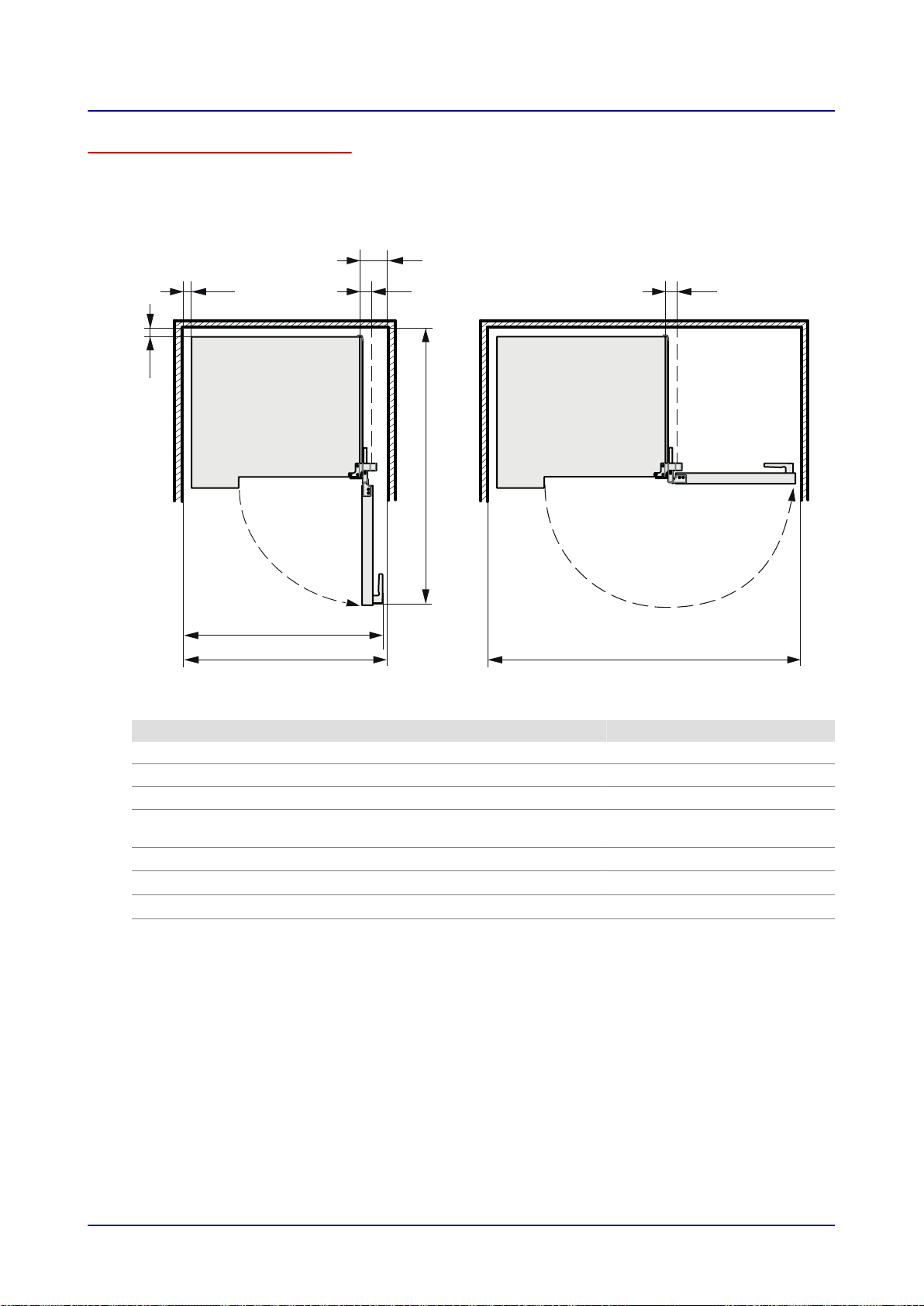
Required space for units with a disappearing door – width and depth
The following diagrams, as well as the following table, show the space required by the unit for various
installation and operating situations, as well as the minimum horizontal clearances required relative to
adjacent walls and surfaces. The safety clearances on the left, right, and rear must be maintained
without exception.
12.20 20.10 20.20
Meaning
B1 Required width when the unit door is open 90° [in] 53 43 53
B2 Required width when the unit door is open 180° [in] 79 61 79
B3 Required width when the disappearing door has been slid back [in] 53 43 53
R Required space on right-hand side when the disappearing door
has been slid back
T Required depth when opening the unit door [in] 73 57 73
Safety clearance on left-hand side [in] 2 2 2
S1
Rear safety clearance [in] 2 2 2
S2
Safety clearance on right-hand side [in] 2 2 2
S3
[in] 6 6 6
Installation Manual 37
Page 38
H1
5 Setup
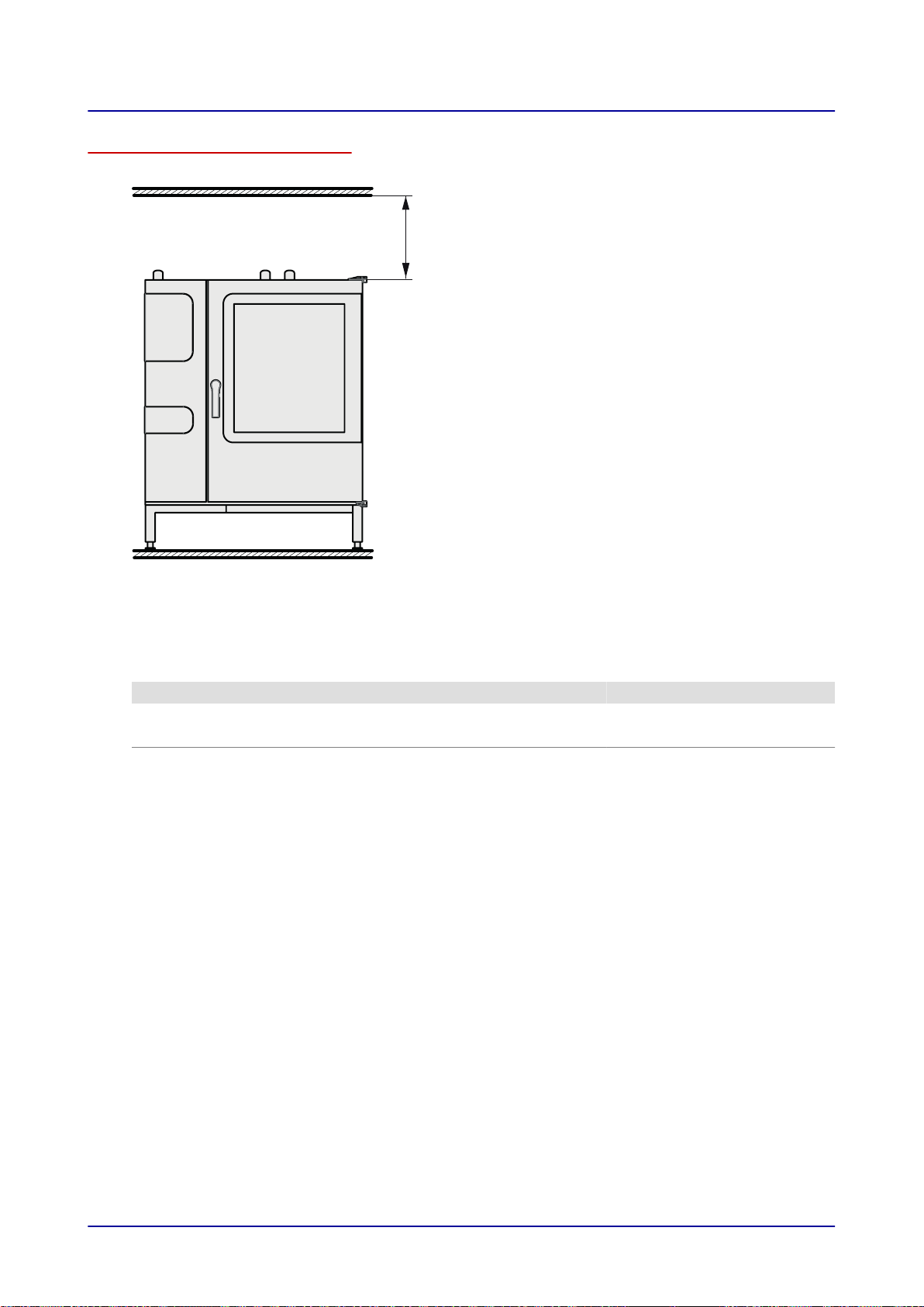
Required space – height
The figure below shows a size 12.20 combi oven used as an example representing all models:
The service technician responsible for setting up the unit must take into account the ceiling's proper‐
ties and any adjacent systems being used (air ventilation system, range hood) when determining the
actual clearance required between the top of the unit and the ceiling.
meant to serve as a reference point for the minimum vertical clearance.
Meaning
Electrical units
H1 Reference point for minimum vertical clearance [in] 20 20 20
Gas units
H1 Reference point for minimum vertical clearance [in] 39 39 39
Vertical clearance H1 is only
12.20 20.10 20.20
Installation Manual 38
Page 39
5 Setup
5.3 Removing the unit from the pallet
Rules for safely lifting the unit
Observe the following rules in order to prevent the unit from toppling over:
■
The unit must be carefully lifted and secured in such a way that it will not tip over.
■
Observe the center of gravity.
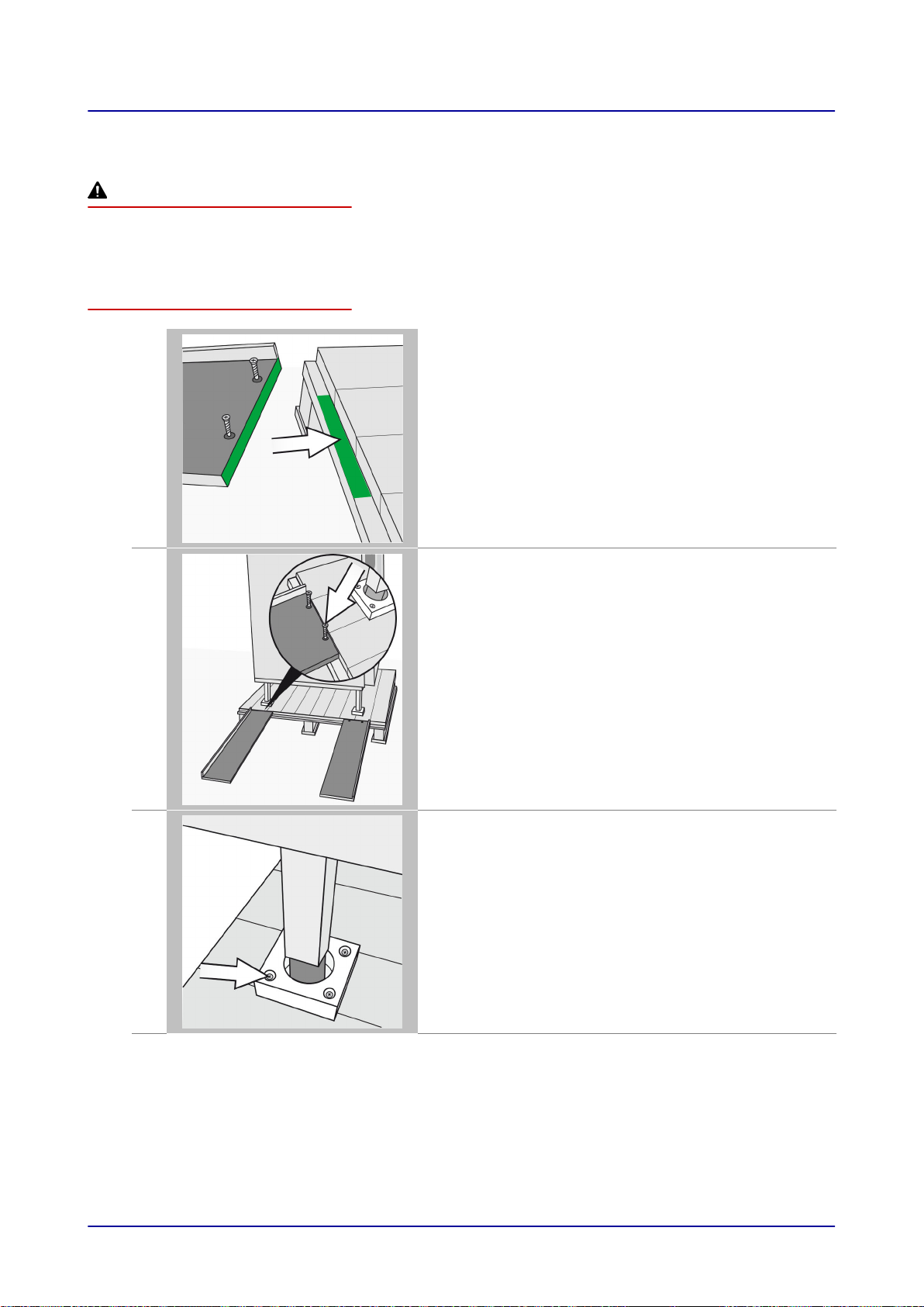
Removing the unit from the pallet (standard model)
1.
2.
Place the guide rails, with the raised edge on the outside,
on the green markings on one of the pallet's sides. Make
sure that the ends of the guide rails are lying right against
the side of the pallet so that the screws will engage the
pallet's lip properly.
Screw the two guide rails together with the pallet.
3.
Remove all the screws from the sliding blocks.
Installation Manual 39
Page 40
5 Setup
4.
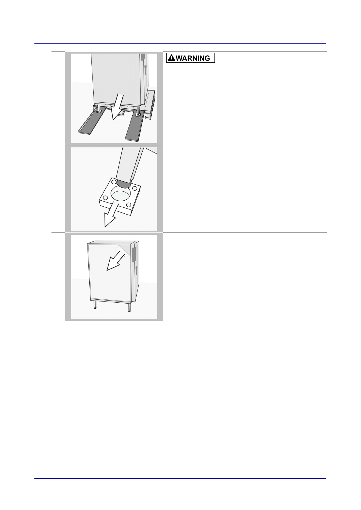
Crush hazard if the unit topples over
■
Before sliding the unit off the pallet, check to make sure
that the guide rails are securely fastened to the pallet.
■
Make sure that none of the unit's feet slip from the guide
rails sideways.
■
Exercise caution when the unit moves from the guide
rails to the non-slip floor.
Use at least two people to slide the unit on the sliding
blocks all the way across the guide rails and onto the floor
all the way to the installation location.
5.
6.
Slightly lift the combi oven and remove the sliding blocks.
Remove the protective film from the combi oven.
Installation Manual 40
Page 41
5 Setup
5.4 Setting Up the Unit on the Floor
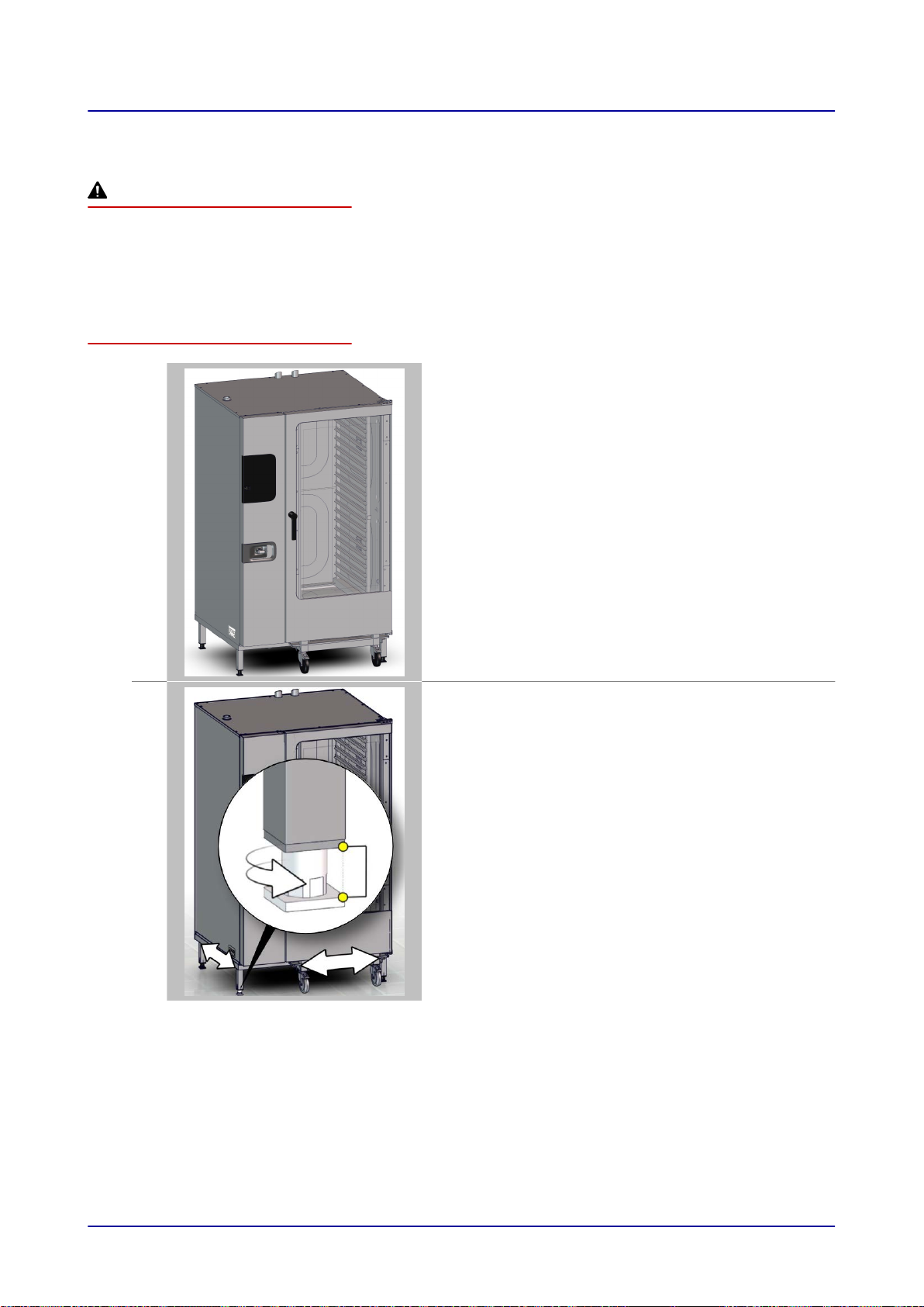
Rules for safely setting up the unit
Observe the following rules in order to ensure that the unit will have the required stability:
■
It must be possible to set up the unit at the installation location in such a way that it will not topple
over or shift. All supporting surface requirements must be met.
■
It must be possible to move the loading trolley all the way to the oven cavity unobstructed on a hori‐
zontal surface.
Setting up the unit
1.
2.
Place the unit on the floor.
Use the unit's height-adjustable feet to level the unit.
Use a spirit level to make sure that the unit is properly
leveled.
Make sure that the loading trolley can move without a
problem into the unit and is in a horizontal position inside
the unit.
The unit's absolute inclination during operation must not
exceed max. 2° (3.5%).
Installation Manual 41
Page 42

6 Installation
6 Installation
6.1 Electrical installation
6.1.1 Planning the Electrical Installation
Meaning
It is crucial for the unit's electrical system to be carefully and correctly installed in order for the unit to
run safely and without any problems. All the rules and specifications specified in this section, as well
as the procedures described, must be followed to the letter.
Rules for safely installing the unit electrically
In order to prevent hazards related to improperly installed electrical connections, make sure to ob‐
serve the following rules:
■
The unit's case must be properly grounded as per generally accepted standards and practices and
connected to an equipotential bonding system.
■
The field installed conductors must be routed through a flexible conduit.
■
While placing the unit into operation, check all electrical connections to make sure they have been
routed properly and installed correctly.
Electrical installation standards and regulations
In order to prevent hazards related to improperly installed electrical connections, make sure to ob‐
serve the following standards and regulations:
■
The connection to the power supply must be installed in accordance with the National Electrical
Code, ANSI/NFPA 70 (current edition); the Canadian Electrical Code, CSA C22.2; all other applica‐
ble national and state laws and regulations; and the local requirements set forth by the relevant lo‐
cal utility companies, trade associations, and authorities.
Equipment provided by the customer and electrical installation rules
The following table shows the equipment that must be provided by the customer and the rules that
have to be followed when making the relevant electrical connections.
Equipment Rules
Fuse The unit must be fused and connected in accordance with all applicable
local regulations and country-specific installation regulations.
Equipotential bonding The unit must be connected to an equipotential bonding system.
Equipotential bonding: An electrical connection that brings the frames of
electrical equipment and other conductive parts to the same or approxi‐
mately the same potential.
Ground fault circuit
interrupter (GFCI)
If installation regulations require for a ground fault circuit interrupter
(GFCI) to be connected upstream as protection, unit leakage circuit inter‐
rupters that are appropriate as per the applicable country-specific regula‐
tions must be used.
If the installation encompasses multiple units, a separate ground fault cir‐
cuit interrupter must be provided for each unit.
Disconnector An easily accessible all-pole power disconnection with a contact gap of at
least 0.12" must be installed. The unit must be connected through this
power disconnector.
The power disconnection will then be used to de-energize the unit before
performing cleaning, repair, and installation work.
Installation Manual 42
Page 43

6 Installation
Recommended ground fault circuit interrupter
The unit features a variable frequency drive (VFD), as well as an integrated EMI filter and a power line
filter. This equipment can result in a leakage current of more than 3.5
mA per VFD.
Use an appropriate ground fault circuit interrupter (GFCI) as required for the relevant rated voltage:
Variable frequency drive (singlephase)
Variable frequency drive (threephase)
Rated voltage
1N~ 120V 60 Hz 3~ 400V 50/60 Hz
3~ 208/240V 60Hz (3/PE)
3~ 208V 60Hz (3/PE)
Recommended ground fault circuit interrupter (GFCI):
Type A Type Certified in conformity with UL
943 and under consideration of the
installation requirements in NEC
NFPA70
Ground fault circuit interrupter characteristics
The ground fault circuit interrupter (GFCI) must have the following characteristics:
■
High-frequency current filtering
■
'Delayed trip' trip characteristic in the case of ground fault interrupters with a trip threshold £30
helps prevent the GFCI from tripping due to capacitor charges and parasitic capacitances when the
unit is powered on
■
'Type SI leakage current protection' trip characteristic in the case of ground fault interrupters with a
trip threshold £30 mA:
helps prevent nuisance tripping
Power supply
mA:
The field installed conductors must be routed through an oil-resistant, liquid-tight conduit. Moreover,
the field installed conductors and the conduit must comply with all local requirements and regulations.
It is recommended for the field installed conductors not to exceed a length of 5½ yd.
In the case of table-top models placed on a base with casters, the field installed conductors must be
routed through a flexible, oil-resistant, liquid-tight conduit that complies with all local requirements and
regulations. The length of the field installed conductors and the length of the flexible conduit used for
table-top models placed on a base with casters must take into account how much the retaining ele‐
ment on the base allows the unit to move. Do not pull or otherwise subject the field installed conduc‐
tors to any tension when moving the whole setup (base and unit).
A specific phase rotation direction or phase sequence is not required when connecting the unit.
Installation Manual 43
Page 44
6 Installation
6.1.2 Performing the Electrical Installation
Prerequisites
Check whether the following prerequisite is met:
■
The unit's connection point has been de-energized and locked and tagged out.
Checking the rating data and electrical connections
1.
2.
3.
Performing the Electrical Installation
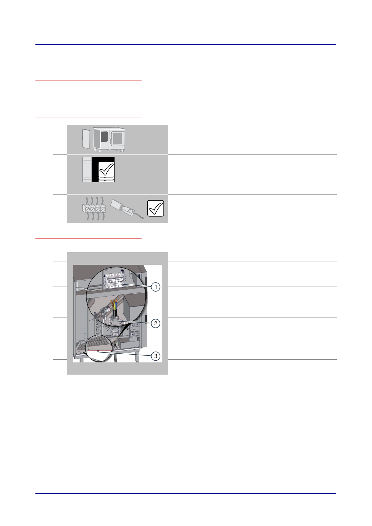
The figure below shows a size 12.20 combi oven used as an example representing all unit sizes:
1.
2.
3.
4.
5.
6.
7.
Remove the unit's side panel.
The circuit diagram and the spare parts list will be located
inside the wiring compartment.
Check to make sure that the electrical rating data on the
nameplate (please refer to
on page 8) matches the specifications in the circuit dia‐
gram and the characteristics of the building's electrical
system. Do not connect the unit unless all specifications
match.
Check all screw and crimp terminal connections on the
unit.
The connections may have become loose during transpor‐
tation.
Remove the unit's side panel.
Connect the unit to an electrical ground system at the in‐
tended connection point (3).
Pull the field installed conductors through the conduit.
Mechanically secure the conduit to the access opening (2)
for the electrical connection.
Use the field installed conductors to connect the unit to the
power supply at terminal block -1X0 (1).
For C4 ES/GS:
If necessary, reset the safety thermostat for the oven cavi‐
ty.
For C4 EB/GB:
If necessary, reset the safety thermostats for the oven cav‐
ity and boiler.
Put the unit’s side panel back in place and check that it is
mounted properly.
'Identifying Your Combi Oven'
Installation Manual 44
Page 45
6 Installation
6.1.3 Connecting the energy optimization system
Purpose of energy optimization system
You can connect the combi oven to an energy optimization system (e.g. SICOTRONIC). Energy opti‐
mization system compensate for peak loads that occur while your units are running and can help lower
your electricity costs as a result.
Setting up the energy optimization system
Set up the energy optimization system as follows:
■
Do not exceed the maximum cable length of 190" between the unit and the energy optimization
system. If there is no other choice, the connection must go through a relay that is at a distance of
190" or less from the unit.
■
The combi oven must be on without interruption for at least eight minutes, since this is the mini‐
mum time required in order to ensure that the cooking temperature setpoint will be reliably reached.
■
The power interruption effected by the energy optimization system must not last longer than
30
seconds, as a longer interruption will result in uncertain cooking results.
When connecting the energy optimization system, observe the circuit diagram and follow the operating
instructions for the system.
Required accessories
You will need the following accessories to connect the energy optimization system:
■
Connection cable for energy optimization system
■
M20 cable fitting
■
Cable ties
Connecting the energy optimizing system
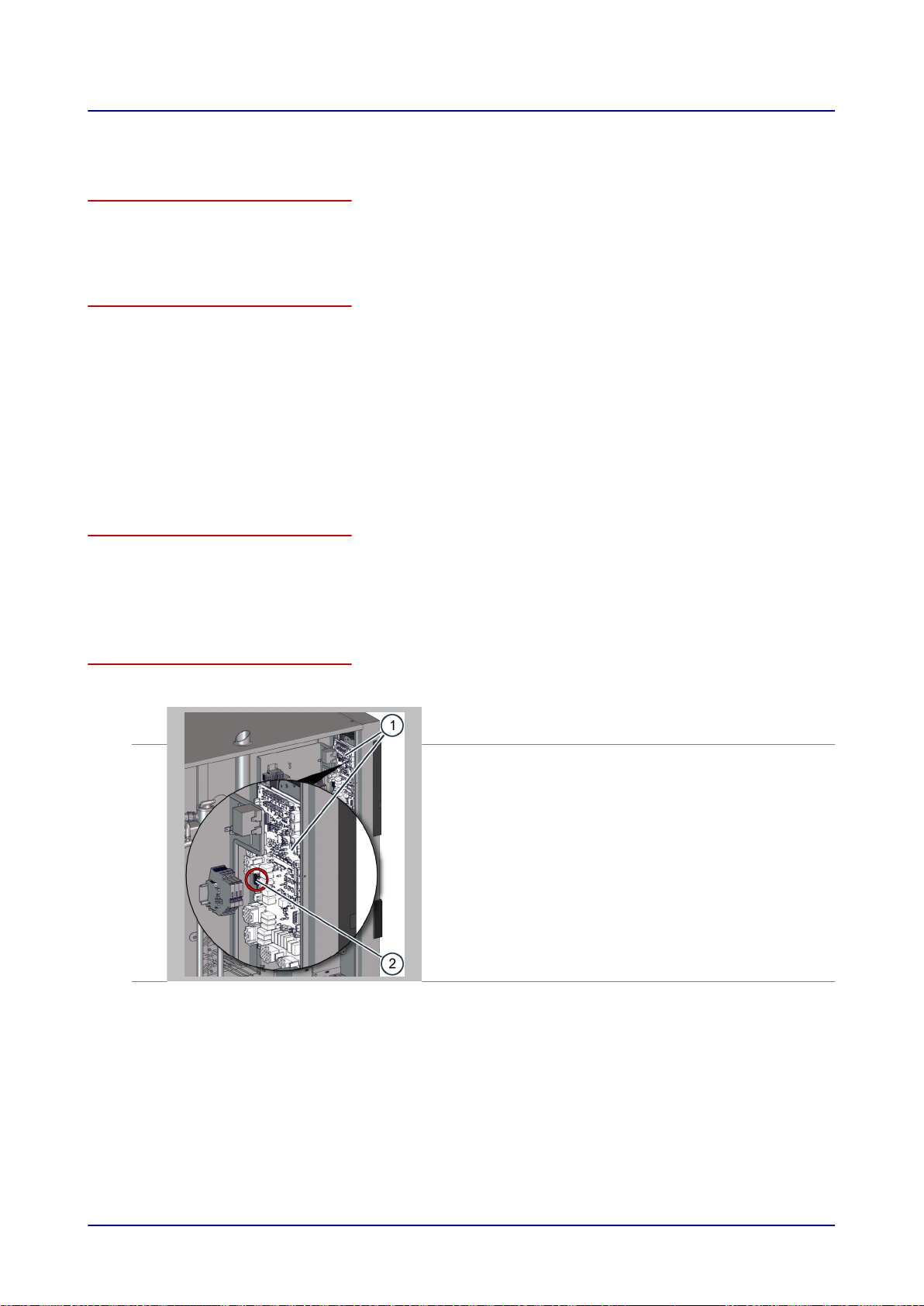
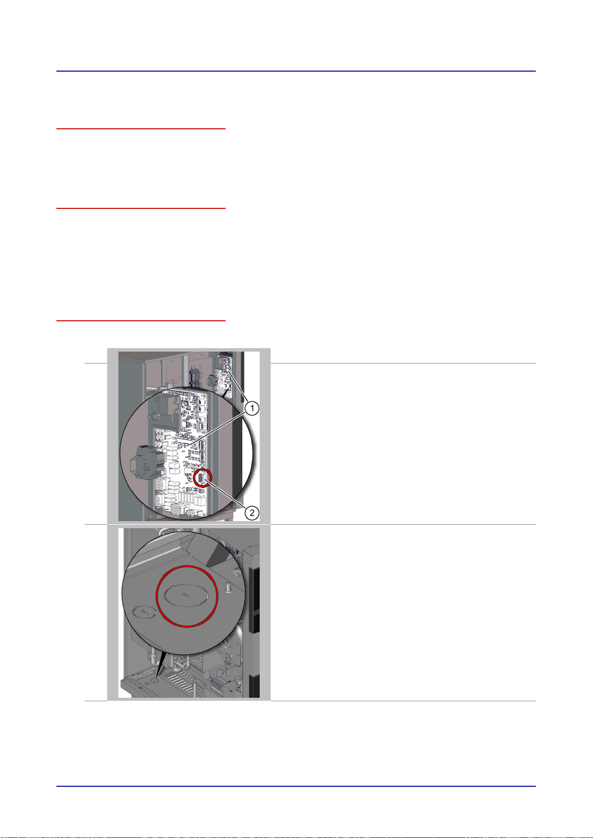
The figure below shows a size 12.20 combi oven used as an example representing all unit sizes:
1.
De-energize the energy optimizing system and the combi
oven.
2.
Remove the side panel from the combi oven in order to
access terminal block -X37 (2) on the system interface
board (SIB) (1) in the area behind the operating panel.
Installation Manual 45
Page 46
6 Installation
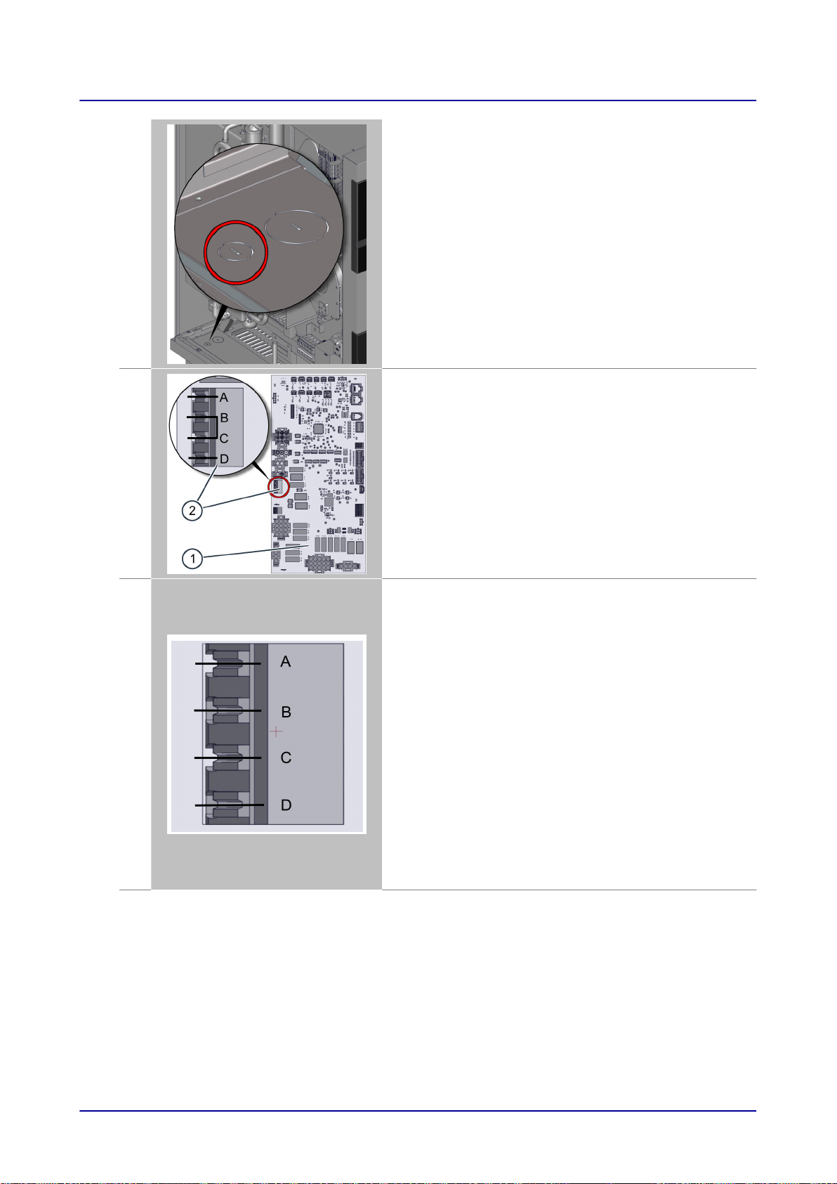
3.
■
Remove the small pre-perforated knockout on the com‐
bi oven's bottom panel. The knockout's location is
shown on the left.
■
Using the cable fitting, guide the energy optimization
system's connection cable through the knockout and in‐
to the combi oven's wiring compartment.
■
Connect the connection cable to the SIB and secure it
inside the wiring compartment, e.g., by
using cable ties
to secure it to the cable harnesses already inside the
compartment.
4.
5.
Remove the jumper between terminals (B) and (C) on ter‐
minal block -X37 (2).
Connect terminals (A), (B), (C), and (D) on terminal block
-X37 (2) to the energy optimization system.
Energy optimiza‐
Terminal Combi Oven
A
Phase (when the com‐
tion system
-
bi oven is turned on)
B
Phase (when the com‐
Electronic relay
bi oven is turned on)
C
The energy optimiza‐
Electronic relay
tion system must con‐
nect heater enable ter‐
minals B and C to
each other with elec‐
tronic relays in order to
allow heating
D
Neutral -
Installation Manual 46
Page 47
6 Installation
6.
7.
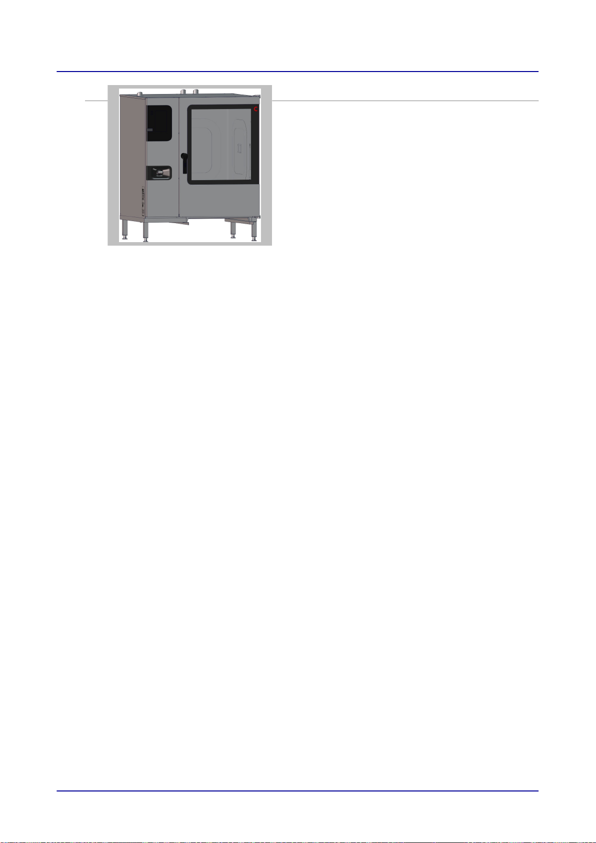
Put the combi oven's side panel back in place.
Place the combi oven and the energy optimizing system
into operation.
Installation Manual 47
Page 48
6 Installation
6.1.4 Connecting the Signal Tower
Signal tower purpose
If a signal tower is electronically connected to the combi oven, the tower will visually and acoustically
indicate the combi oven's current operating state using acoustic signals and three indicator lights
(green, yellow, red). This pilot device, which signals the combi oven's operating state, can be seen
and heard across large distances.
Required accessories
The equipment included with the signal tower includes the following original accessories, which you
will need in order to connect the signal tower to the combi oven:
■
Connection cable (approx. 10.9
■
NPS 2" gland grommet
You will also need the following additional accessories:
■
Cable ties
Connecting the Signal Tower
The figure below shows a size 12.20 combi oven used as an example representing all unit sizes:
yards long) with an M12 connector
1.
2.
3.
De-energize the combi oven.
Remove the side panel from the combi oven in order to
access terminal block X32 (2) on the system interface
board (SIB) (1) in the area behind the operating panel.
■
Remove the large pre-perforated knockout on the combi
oven's bottom panel. The knockout's location is shown
on the left.
■
Using the gland grommet, guide the signal tower's con‐
nection cable through the knockout and into the combi
oven's wiring compartment.
■
Connect the connection cable to the SIB and secure it
inside the wiring compartment, e.g., by using cable ties
to secure it to the cable harnesses already inside the
compartment.
Installation Manual 48
Page 49
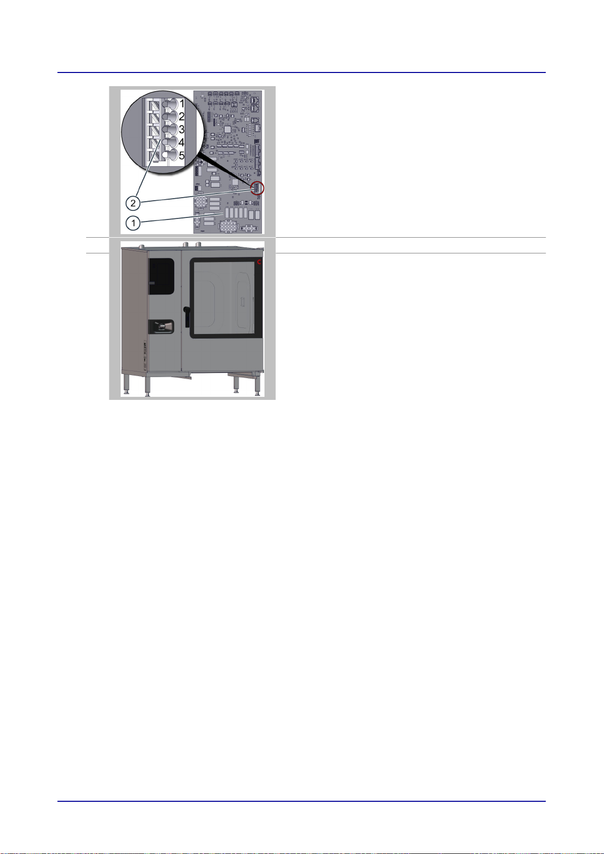
6 Installation
4.
5.
6.
Connect the signal tower's connection cable to the combi
oven, observing the following pinout:
Pin Signal Wire color
1
2
3
4
5
Put the combi oven's side panel back in place.
Place the combi oven and the signal tower into operation.
GND BU (blue)
Signal: Buzzer GY (gray)
Signal: Red light BK (black)
Signal: Yellow light WH (white)
Signal: Green light BN (brown)
Installation Manual 49
Page 50
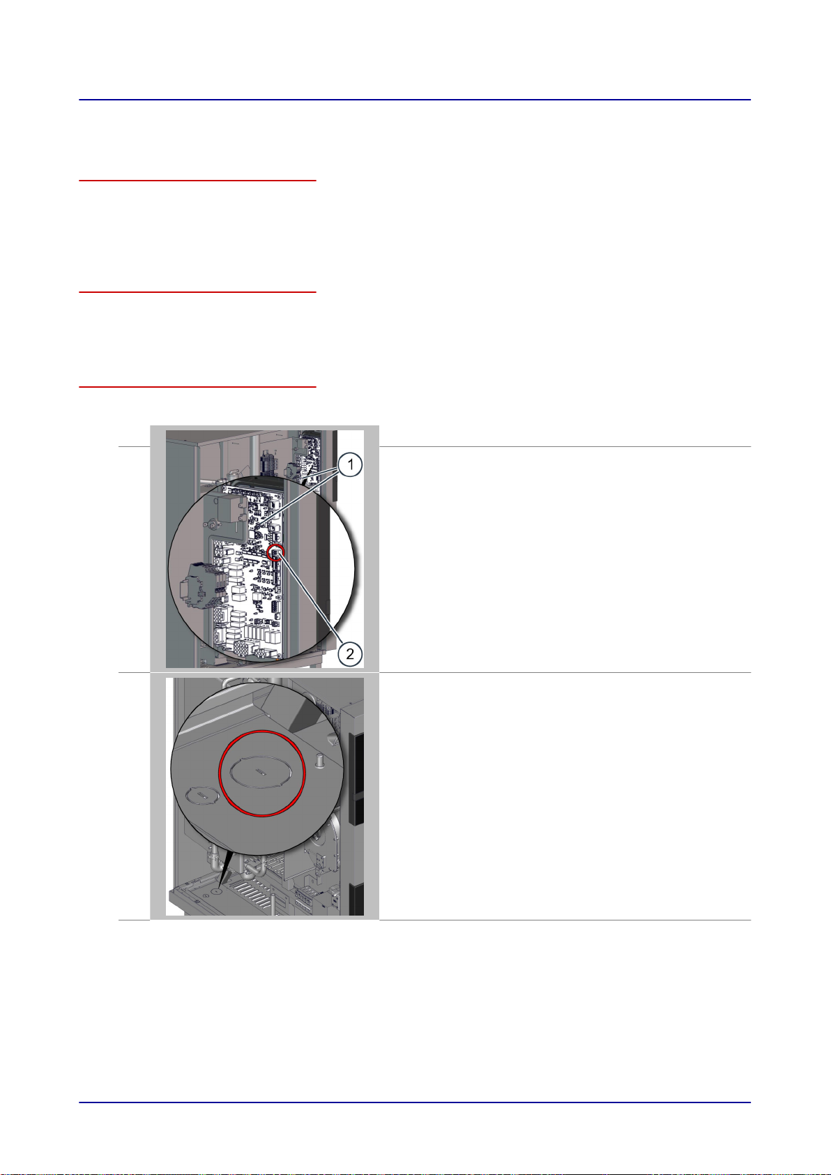
6 Installation
6.1.5 Connecting the Water Treatment Filter Monitoring System
Water treatment filter monitoring system purpose
You can electrically connect the combi oven to the remote indicator for a connected water treatment
filter. When you do so, the combi oven's software will monitor the water treatment filter's condition. The
system will provide a warning when the filter's capacity is down to 10% and the water treatment filter
needs to be replaced soon.
Required accessories
■
Two-conductor, oil-resistant connection cable (approx. 80" long)
■
NPS 2" gland grommet
■
Cable ties
Connecting the Water Treatment Filter Monitoring System
The figure below shows a size 12.20 combi oven used as an example representing all unit sizes:
1.
2.
3.
De-energize the combi oven.
Remove the side panel from the combi oven in order to
access terminal block X33 (2) on the system interface
board (SIB) (1) in the area behind the operating panel.
■
Remove the large pre-perforated knockout on the combi
oven's bottom panel. The knockout's location is shown
on the left.
■
Using the gland grommet, guide the water treatment fil‐
ter monitoring system's connection cable through the
knockout and into the combi oven's wiring compart‐
ment.
■
Connect the connection cable to the SIB and secure it
inside the wiring compartment, e.g., by using cable ties
to secure it to the cable harnesses already inside the
compartment.
Installation Manual 50
Page 51
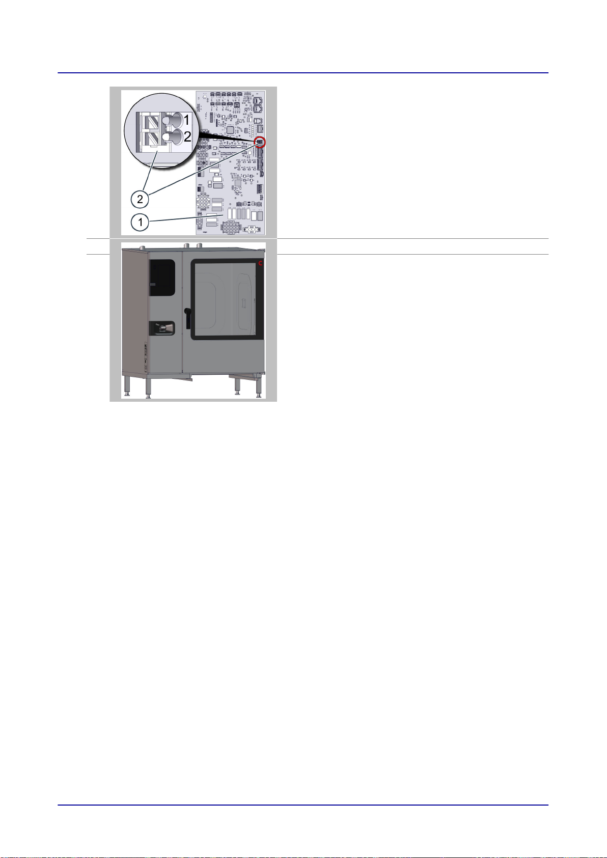
6 Installation
4.
5.
6.
Connect the water treatment filter monitoring system's
connection cable to the combi oven, observing the follow‐
ing pinout:
Pin Signal
1
2
Put the combi oven's side panel back in place.
Place the combi oven and the water treatment filter moni‐
toring system into operation.
Signal
GND
Installation Manual 51
Page 52

6 Installation
6.2 Gas Installation
6.2.1 Planning the Gas Installation
Rules for safely installing the unit’s gas system
In order to prevent hazards related to improperly installed gas connections, make sure to observe the
following rules:
■
The combi oven is designed to work with a specific type of gas (check the unit's nameplate). In or‐
der to run the combi oven with other types of gas, it will first need to be retrofitted by qualified staff
from an authorized service company.
■
Always check all the connection points on components conveying gas for leaks after connecting
the gas system and after performing any work on these components. Before placing the combi
oven into operation, make sure that none of the specified connection points outside or inside the
unit have any leaks.
Gas unit type
The combi oven belongs to the following gas unit type category:
Gas unit type Meaning
B23 Open-flued gas appliances
■
With a burner fan in front of the burner
■
With no draft diverter
Equipment provided by the customer and gas installation rules
The following table shows the equipment that must be provided by the customer and the rules that
have to be followed when making the relevant electrical connections:
Equipment Rules
Fixed connection The unit is designed for a permanent connection installed on-site. Gas
connection location: point J in the connection drawing.
The unit must be mechanically secured.
Gas shut-off device A gas shut-off device must be installed close to the unit. This gas shut-off
device must be easily accessible and positioned in such a way that it can
be closed even in hazardous situations.
Pressure regulator A pressure regulator must be installed if the supply flow pressure is too
high.
All connection parts All connection parts installed on-site must be inspected in compliance with
all applicable local and country-specific regulations.
Ensuring that there is a proper combustion air supply
Based on the installation setup and the combi oven's output, all measures required in order to ensure
that the unit will be supplied with sufficient combustion air should be taken in accordance with all appli‐
cable local regulations and standards. Make sure, as the gas technician responsible for the installa‐
tion, that the unit will be supplied with sufficient combustion air.
Keep the following in mind:
■
The required combustion air will depend on the connection rating – please refer to the 'exhaust gas
volume' in the 'Technical Data' on page
76 section.
Installation Manual 52
Page 53

6 Installation
Ensuring that there is proper ventilation
The unit will produce combustion exhaust gases that need to be discharged into the open through an
appropriate flue. Make sure to follow all the instructions and indications in the
tion on page 33 without exception.
In order to prevent combustion exhaust gases that are harmful to health from reaching impermissible
concentration levels, you, as the gas technician responsible for the installation, must ensure that the
unit is installed in such a way that appropriate ventilation conditions for running the combi oven will
always be guaranteed.
Exhaust gas temperature
The undiluted exhaust gas may reach temperatures of up to 930 °F.
Comply with all fire safety regulations.
'Adjacent Systems' sec‐
Installation Manual 53
Page 54
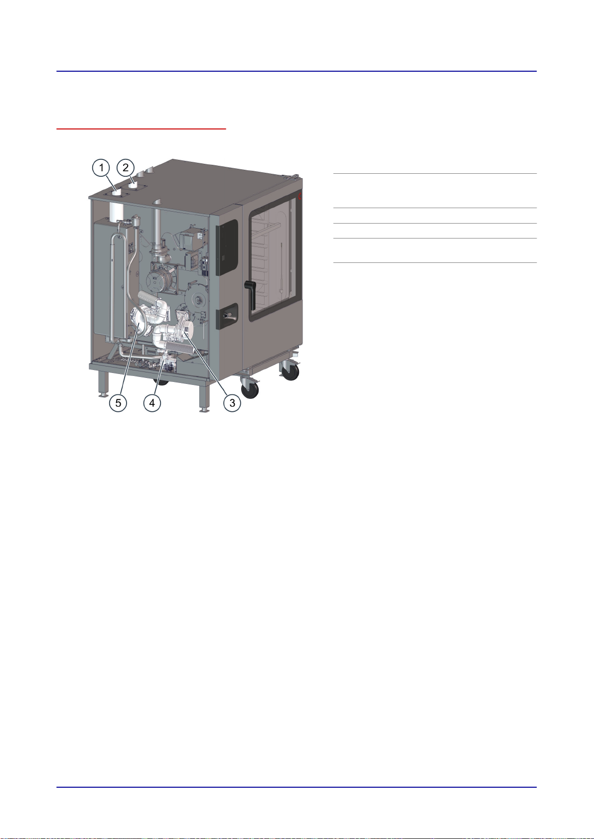
6 Installation
6.2.2 Forced Air Burner and Gas Main Valve Locations
Forced air burner location for 12.20 unit size
The figure below shows a size 12.20 combi oven with a boiler:
No. Designation
1
2
3
4
5
Boiler burner exhaust outlet (found
in boiler units only, i.e., units with a
sprayer will not have this outlet)
Convection burner exhaust outlet
Convection burner
Gas main valve, gas connection at
the bottom of the unit
Boiler burner (found in boiler units
only, i.e., units with a sprayer will not
have this outlet)
Installation Manual 54
Page 55
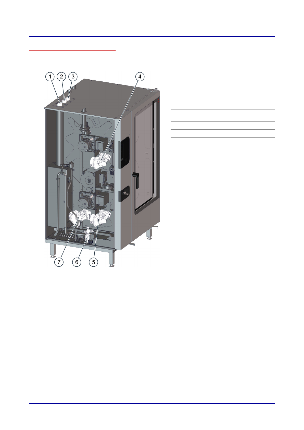
6 Installation
Forced air burner locations in unit sizes 20.10 and 20.20
The figure below shows a size 20.20 combi oven with a boiler used as an example representing all
size 20.10 and 20.20: gas units:
No. Designation
1
2
3
4
5
6
7
Boiler burner exhaust outlet (found
in boiler units only, i.e., units with a
sprayer will not have this outlet)
Lower convection burner exhaust
outlet
Upper convection burner exhaust
outlet
Upper convection burner
Lower convection burner
Gas main valve, gas connection at
the bottom of the unit
Boiler burner (found in boiler units
only, i.e., units with a sprayer will not
have this outlet)
Installation Manual 55
Page 56

6 Installation
6.2.3 Performing the Gas Installation
Prerequisites
Check whether the following prerequisite is met:
■
A gas shut-off device has been installed on-site.
Required tools
■
Leak detector spray / gas detector
Performing the Gas Installation
Check the type of gas, the gas pressure, and the gas con‐
1.
nection rating against the specifications on the unit's
nameplate.
Do not place the unit into operation or connect it to the gas
supply point unless all specifications match.
Connect the gas connection.
2.
Make sure that none of the connection points outside the
3.
unit are leaking.
Find out where the burners and their components are lo‐
4.
cated and familiarize yourself with the burners' configura‐
tion.
Turn on the unit.
5.
Make sure that none of the connection points outside or
6.
inside the unit are leaking. If required, fix any leaking con‐
nection points.
Start a cooking profile with the 'Hot air' operation mode.
7.
Measure the supply flow pressure at the gas valve.
8.
Result:
■
If the supply flow pressure exceeds the specified upper
limit, it can be reduced if necessary.
■
If the supply flow pressure falls below the specified low‐
er limit, you, as the installer, will not be able to correct
the problem.
■
If the reading falls within the specified limits, continue to
step 9.
■
If you cannot get the supply flow pressure to fall within
the specified limits, use the gas shut-off device to shut
off the gas supply to the combi oven and stop installing
the system.
Measure the burner's CO emissions.
9.
Do not place the unit into operation unless the emissions
fall within the specified limits.
Turn off the unit.
10.
Notify the following parties (if required) of the fact that you
11.
have installed the gas unit and the corresponding system
components:
■
Gas provider
■
The appropriate authorities as required by local regula‐
tions
'Gas operation specifications' in
'Technical Data' on page
76
‘Forced Air Burner and Gas Distri‐
bution Unit Locations' on page 54
'Measuring the Supply Flow Pres‐
sure' on page 57
'Measuring the Exhaust Gas Val‐
ues' on page 58
Installation Manual 56
Page 57
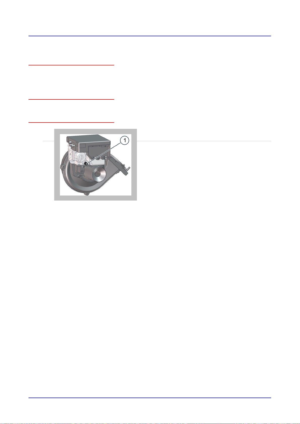
6 Installation
6.2.4 Measuring the Supply Flow Pressure
Prerequisites
■
A gas shut-off device has been installed on-site.
■
The gas system must have been installed as indicated in the
page 56 all the way to the 'Measure the supply flow pressure' step.
Required tools
■
Pressure measuring instrument
Measuring the Supply Flow Pressure
'Performing the Gas Installation' on
1.
2.
Measure the supply flow pressure at the gas valve (1) on
the forced air burner.
Compare the measured value with the specified limits –
refer to 'Gas operation specifications' in
'Technical Data.'
on page 76
Result:
■
If the measured supply flow pressure is lower than the
required values:
■
Notify your gas utility. Do not place the unit into oper‐
ation. Shut off the gas to it.
■
If the measured supply flow pressure is higher than the
required values:
■
Restrict the supply flow pressure.
Installation Manual 57
Page 58
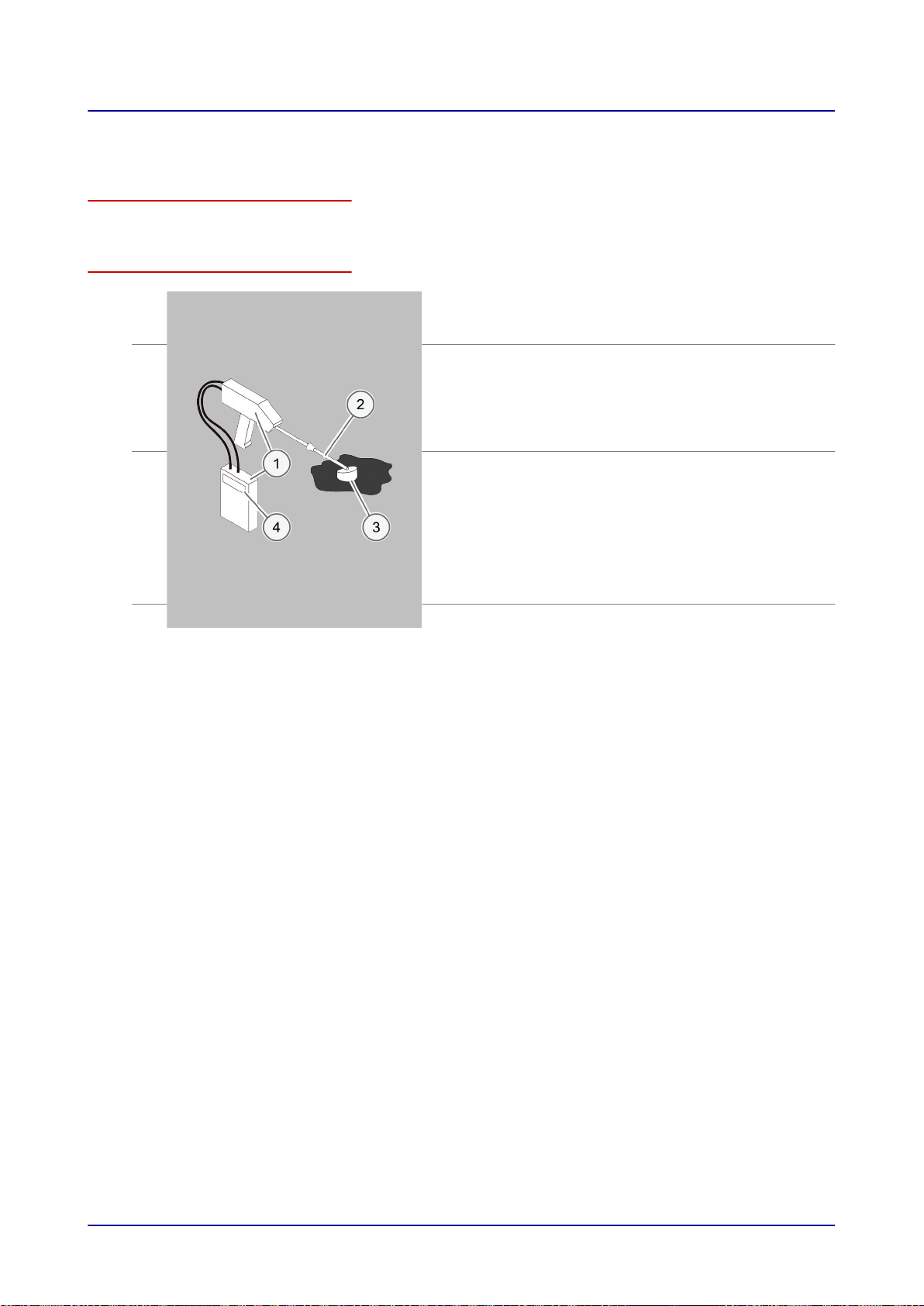
6 Installation
6.2.5 Measuring the Exhaust Gas Values
Required tools
■
Exhaust gas analyzer
Measuring the Exhaust Gas Values
1.
2.
3.
4.
Thread the flue gas analyzer's (1) probe (2) into the ex‐
haust outlet (3) for the burner for which you will be per‐
forming the measurement.
Measure the exhaust gas values.
Make sure to follow the operating instructions in the ana‐
lyzer’s manual.
Additional information:
If the analyzer shows approx. 21% O2 or nothing, the
probe is in the wrong exhaust outlet.
After one minute, check the analyzer’s readings (4) and
compare them with the specified limit – please refer to
'Gas operation specifications' in
'Technical Data.' on page
76
■
If the limit is being exceeded, the unit needs to be
checked as indicated in the adjustment instructions in
the servicing documentation.
Otherwise:
■
Continue to step 4.
Document the analyzer's readings.
Installation Manual 58
Page 59

6 Installation
6.3 Network Connection
6.3.1 Planning the Network Connection
Meaning
It is crucial for the unit's network connection to be carefully and correctly installed in order for the unit
to run safely and without any problems and to have the connection to the Internet required for this pur‐
pose.
Contact your service partner for more information.
Equipment provided by the customer and network connection rules
The following table shows the equipment that must be provided by the customer and the rules that
have to be followed when making the relevant electrical connections.
Equipment Rules
RJ45 port A network jack for the combi oven must be installed close to the unit.
If connecting multiple combi ovens, a separate network jack must be in‐
stalled for each unit. Alternatively, the units can be networked together by
installing a router.
Installation Manual 59
Page 60

6 Installation
6.4 Water connections
6.4.1 Water supply
Water connection standards and regulations
Make sure to comply with all national and state laws and regulations that apply to the water connec‐
tion, as well as with all applicable local requirements and regulations set forth by the relevant local wa‐
ter utilities and authorities. These include, but are not limited to:
■
Latest edition of the International Plumbing Code published by the International Code Council (ICC)
or the Uniform Plumbing Code published by the International Association of Plumbing and Mechan‐
ical Officials (IAPMO)
■
The Food Service Sanitation Manual published by the Food and Drug Administration (FDA)
■
The standards published by the National Sanitation Foundation (NSF)
The unit must be installed with an appropriate backflow preventer in order to comply with all applicable
federal, state, and local laws and regulations.
Water connection configuration
The unit is designed for a permanent connection to the water supply via a connecting hose with a min‐
imum diameter of 1/2".
The following parts in the scope of supply are required for a proper water connection.
■
Two 3/4" water supply lines
■
Two G3/4" - 3/4" GHT adapters (preinstalled)
The adapters can be used if the enclosed supply lines are not long enough. The adapters must be
removed from the water connections on the unit side and stored in a safe place if the supply lines are
long enough.
Water quality and water hardness
■
Ask your local water company for information regarding the quality and hardness of the water you
get or check the water quality as explained in
■
For information on the required properties for the drinking water used with the unit, please refer to
'Water Quality' in the 'Technical Data' section.
■
If required, use suitable water treatment solutions. These can include, for instance, installing a wa‐
ter filter and/or a full water treatment system.
■
Follow the steps in the 'Checking the Water Quality' on page 63 section in order to ensure that
the required water quality values are met once the water goes through your water treatment sys‐
tem.
■
Please note that for units with a boiler, the specified target values are for hardness (ppm CaCO3).
Other minerals dissolved in water may produce deposits as well. The need for removing these de‐
posits will increase depending on the type of minerals in the water and as a function of the length of
time that the unit has been running. These deposits can be removed with a chemical cleaning
agent such as a descaler or by installing an upstream water treatment system (partial demineraliza‐
tion). The measures taken must be discussed with Technical Service on a case-by-case basis.
'Checking the Water Quality' on page 63.
Installation Manual 60
Page 61
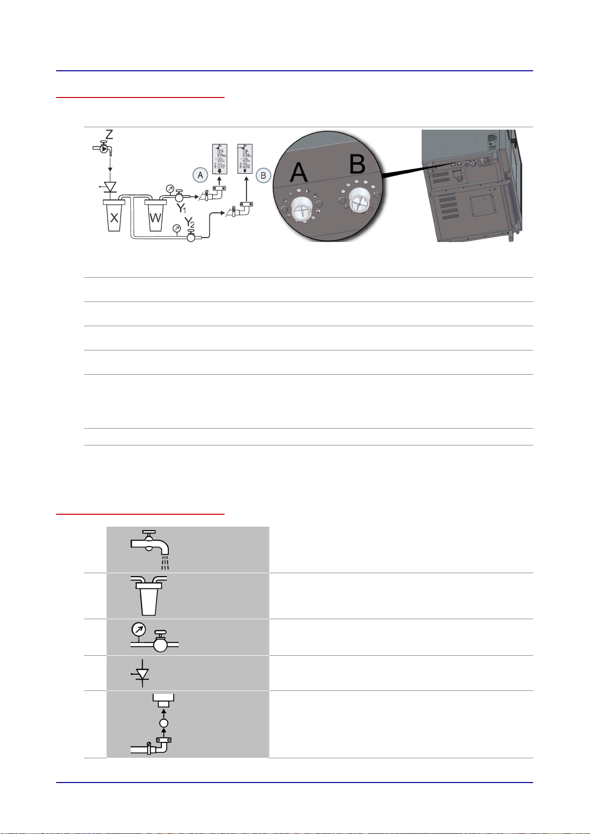
V
6 Installation
Connection diagram with water treatment system
Connection diagram Unit connections
No. Designation Explanation
A
B
Z
X
W
Y1/Y
V
Water connection for boiler or
water injection
Water connection for cleaning
and recoil hand shower
Water line provided by the cus‐
tomer
0.003" sediment filter A 0.003" sediment filter needs to be installed if the water
Water treatment system for soft‐
ening the water until it reaches
the required soft water quality
(can be omitted if the soft water
quality is already adequate)
Shut-off devices Water valves
2
Suitable backflow preventer (re‐
quired only for systems with
sprayer if required by NFS; oth‐
erwise optional)
For water quality information, refer to the 'Technical Data'
on page
For water quality information, refer to the 'Technical Data'
on page 76 section
Water quality: Drinking water
has a lot of impurities.
Recommendation: Partial demineralization cartridge
The unit must be installed with an appropriate backflow
preventer in order to meet the relevant NSF requirements.
76 section
Installing the water supply connection as indicated in the connection diagram
1.
2.
3.
4.
5.
Installation Manual 61
Flush the water connection on the on-site water line (Z).
Install the sediment filter (X) and, if necessary, a water
treatment system (W).
Install a separate shut-off device for each unit (Y or Y1/
Y2).
If a backflow preventer (V) is required (see connection di‐
agram), install it in the water supply line.
Connect the unit as shown in the ‘Connection drawing' on
page 88
.
Page 62
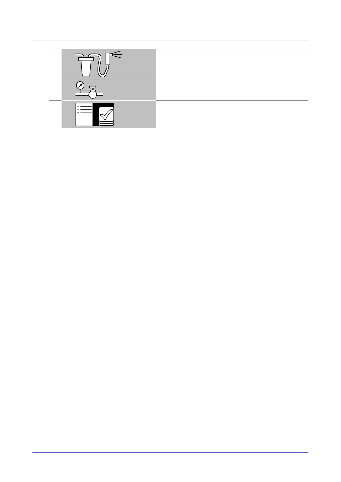
6 Installation
6.
7.
8.
Flush the sediment filter by using the recoil hand shower.
Once you are done installing the water connection, close
the shut-off device.
Inform the user of the maintenance intervals for the filters
and for the water treatment system (if any).
Installation Manual 62
Page 63

6 Installation
6.4.2 Checking the water quality
Required tools
You will need the following tools:
■
1 sample jar for getting a sample
■
1 conductivity meter (part No. 3019007)
■
A general hardness and carbonate hardness analysis kit, including two beakers (part No. 3019010)
■
Protective gloves
Checking the water quality
Measure the water's conductivity and total hardness. To do so, follow the instructions for the meter
and the analysis kit.
Compare the measured values with the required values in the
'Technical Data' on page 76 section.
Installation Manual 63
Page 64
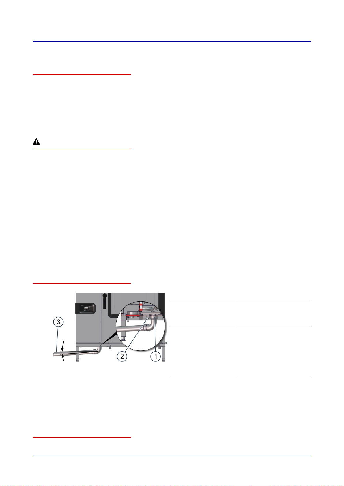
6 Installation
6.4.3 Drain Connection
Drain connection standards and regulations
Make sure to comply with all national and state laws and regulations, as well as with all applicable lo‐
cal requirements and regulations set forth by the relevant local utilities and authorities, that apply to
the drain connection and to the wastewater's properties. These include, but are not limited to:
■
Latest edition of the International Plumbing Code published by the International Code Council (ICC)
or the Uniform Plumbing Code published by the International Association of Plumbing and Mechan‐
ical Officials (IAPMO)
■
The Food Service Sanitation Manual published by the Food and Drug Administration (FDA)
■
The standards published by the National Sanitation Foundation (NSF)
Rules for safely installing the drain connection
In order to prevent hazards related to an improperly installed drain connection, make sure to observe
the following rules:
■
The drain pipes' material must be able to withstand a temperature of 140
■
The drain pipe must not taper or have any other diameter-reducing deformations at any point.
■
The drain pipe's minimum diameter will depend on the pipe's total length and the number of elbows
used. For a pipe length of up to 6 feet and a maximum of two elbows, the minimum inner diameter
will be 2". For a pipe length of 6 to 12 feet or a maximum of three elbows, the minimum inner diam‐
eter will be 2½".
■
The drain pipe must have a downward slope of min. 3.5% (2°).
■
Do not directly connect the unit drain to the sewer system vertically.
■
The connection between the drain pipe and the sewer system must be located outside the perime‐
ter of the unit's base area. Due to potential wastewater vapors, there must not be a drain connec‐
tion or open sewer line below the unit's base area.
■
The drain connection must be implemented using a rigid, naturally ventilated pipe.
■
A ventilation clearance of at least 1" must be maintained between the end of the drain pipe and the
upper edge of the drain or pan.
■
Do not connect any other units to the combi oven's drain pipe.
■
Do not connect the combi oven to any other units' drain pipe.
°F.
Connection diagram
Installing the drain connection
Connect the unit as shown in the connection diagram.
No. Designation Function
1
Appliance drain At the bottom of the unit,
connection point C – please
refer to 'Connection draw‐
ing' on page
2
Safety overflow■At the bottom of the unit,
connection point M –
please refer to 'Connec‐
tion drawing' on page
88
■
Used to drain water in the
event of a failure (block‐
age)
3
Drain pipe
■
Minimum inner diameter
= 2"
■
Downward slope: min.
3.5% (2°)
Drain options:
■
Open pan
■
Channel
88
Installation Manual 64
Page 65
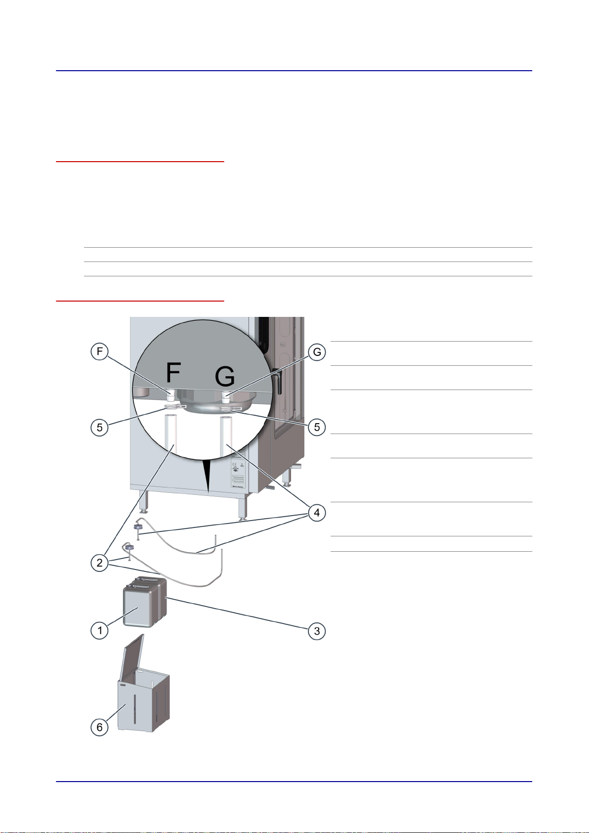
6 Installation
6.5 Installing the fully automatic oven cleaning system
6.5.1 Components of Fully Automatic Oven Cleaning System
Cleaning agents and rinse aid
Only use the products specified here in order to clean the combi oven.
NOTICE! The warranty will be void if there is any damage that can be traced back to the use of incor‐
rect cleaning agents.
The following table lists the cleaning agents and rinse aids that can be used:
Designation Product Label color
Cleaning agents ConvoClean forte / new Red
Rinse aid ConvoCare Green
Components and Configuration of Fully Automatic Oven Cleaning System with Connected Canisters
No. Designation Color cod‐
ing
Unit connection for
F
rinse aid
Unit connection for
G
cleaning agent
Canister with
1
ConvoCare rinse aid
(ready-to-use solution
with a defined mix ratio)
Suction tube with suc‐
2
tion nozzle for rinse aid
Canister with
3
ConvoClean new or
ConvoClean forte
cleaning agent
Suction tube with suc‐
4
tion nozzle for cleaning
agent
D10 wire hose clamp -
5
Box for cleaning agent
6
canister (optional ac‐
cessory)
Green (in‐
scription)
Red (in‐
scription)
Green (la‐
bel)
Green
(tube)
Red (label)
Red (tube)
-
Installation Manual 65
Page 66

6 Installation
Box for cleaning agent canister (optional accessory)
The box for the cleaning agent canister (6) is an optional combi oven accessory that is available from
the manufacturer.
The box can be screwed onto a wall using the holes in the back panel. In order to make it easier to
clean the kitchen floor, you can fasten the box at a certain distance from the floor. When doing so,
make sure to observe the requirements described in 'Installation location for cleaning agent and rinse
aid canisters.'
Installation location for cleaning agent and rinse aid canisters
Set up the canisters as follows:
■
The canisters should be easily accessibly on a flat, level surface next to the device.
■
The canister's supporting surface must not be higher than the edge where the feet and the unit
case meet.
■
The canister's supporting surface must not be more than 40
inches below this edge.
Installation Manual 66
Page 67
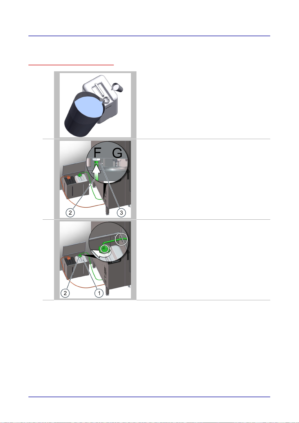
6 Installation
6.5.2 Connecting the Fully Automatic Cleaning System
Connecting the fully automatic oven cleaning system with canisters
1.
2.
Mix the included ConvoCare Concentrate with soft water
in the empty canister for ConvoCare rinse aid.
Make sure to follow the operating manual instructions on
mixing ConvoCare rinse aid in canisters.
Slip the green suction tube (2) for ConvoCare rinse aid
onto the barbed nipple on the rear bulkhead fitting (F) and
secure the tube using the wire hose clamp (3) (see
'Rinse-aid connection' adhesive label on the left unit
side).
3.
Insert the suction nozzle on the green suction tube (2) in‐
to the rinse aid canister (1). The tube must be routed
without any kinks and the canister's vent opening must be
open and clear.
Installation Manual 67
Page 68
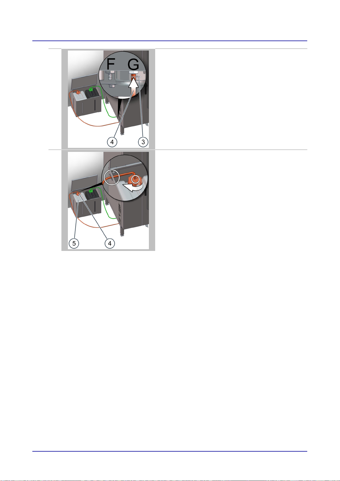
6 Installation
4.
5.
Slip the red suction tube (4) for ConvoClean forte clean‐
ing agent onto the barbed nipple on the front bulkhead fit‐
ting (G) and secure the tube using the wire hose clamp
(3) (see 'Cleaning-agent connection' adhesive label on
the left unit side).
Insert the suction nozzle on the red suction tube (4) into
the cleaning agent canister (5). The tube must be routed
without any kinks and the canister's vent opening must be
open and clear.
Installation Manual 68
Page 69
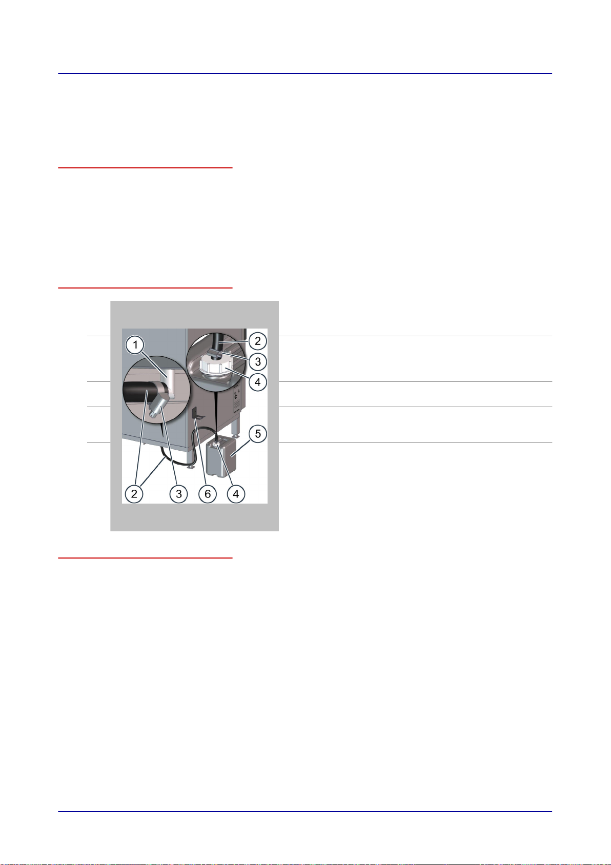
6 Installation
6.6 Installing the Grease Collection Canister
6.6.1 Connecting the Grease Collection Canister
Required accessories
ConvoGrill includes the following original accessories, which you will need in order to connect the au‐
tomatic grease management system. Make sure to use these original accessories exclusively:
■
Connection tube with attached rotating canister screw closure
■
Grease collection canister (empty canister for pumped-out grease)
■
Hose clamp for securing the tube connection on the combi oven
■
Forked holder for holding the canister screw closure with the connection tube while emptying and
cleaning the grease collection canister
Connecting the grease collection canister (ConvoGrill)
1.
2.
3.
4.
5.
Grease collection canister installation location
Set up the grease collection canister as follows:
■
The canister must be in an upright position and easily accessibly on a flat, level surface next to the
unit.
■
The canister's supporting surface must not be more than 6" above the contact point between the
unit and its base.
■
The operator's working area must be kept clear.
Check the accessories for damage. Continue with the in‐
stallation only if the parts are undamaged and have no
leaks.
Slip the open end of the automatic grease management
system's connection tube (2) onto the drain (1) at the
back of the combi oven's bottom. Then secure the tube
(2) using the hose clamp (3).
Screw the canister screw closure (4) on the connection
tube (2) onto the grease collection canister (5).
Place the grease collection canister (5) in an adequate
spot and make sure that the connection tube (2) has no
kinks at any point.
Secure the forked holder (6), which is meant for holding
the canister screw closure (4) with the connection tube, at
an accessible point close the drain (1). To do this, use the
double-sided adhesive tape on the back of the holder or
the pre-drilled holes on the holder.
On units with a disappearing door:
Do NOT place the holder (6) on the combi oven case side
along which the unit door is slid back.
Installation Manual 69
Page 70

7 Placing into operation
7 Placing into operation
7.1 Working Safely When Putting the Unit Into Operation
For your safety when working with/on the combi oven
Before placing the combi oven into operation, read and understand the rules, risks, and hazards speci‐
fied in the 'For Your Safety' section and follow all the corresponding instructions without exception.
Follow the relevant instructions in the operating manual when testing cooking and cleaning sequen‐
ces.
What to do if you smell gas
If you smell gas, follow the steps below without exception:
■
Immediately shut off the gas.
■
Thoroughly ventilate the room.
■
Do not operate any electrical devices or equipment. Make sure not to cause any sparks.
■
Evacuate the building.
■
Call the gas utility and, if necessary, the fire department on a telephone found outside the hazard‐
ous area.
Basic rules for safe operation
If the combi oven is moved in an impermissible manner after installation (on purpose or by accident),
do not continue to operate the unit unless all the following requirements are met:
■
The unit and the accessories being used do not have any obvious damage.
■
The supply lines installed for electrical power, water, wastewater, and cleaning agents do not have
any obvious damage, have a secure fit, are not dripping anywhere, and appear to be safe and fully
functional after a visual inspection.
■
The 'Requirements concerning the combi oven's functional capability on page
■
The 'Requirements concerning the combi oven's surroundings on page 19' are being met.
■
All warning labels are at their intended location.
19' are being met.
Gas units only:
■
A service technician has checked all the components in the combi oven that convey gas in order to
make sure that there are no leaks at any of their connection points. Moreover, the technician has
checked to make sure that none of the specified points outside and inside the unit have any leaks.
Rules for safely running the unit
In order to avoid hazards, follow the rules below when running the unit:
■
Make sure to only use your hands when using the unit’s controls (buttons, switches, touchscreens).
■
Do not cover, obstruct, or block the exhaust vents, exhaust outlets, or ventilation ports at the top of
the unit or the ventilation openings at the bottom.
■
Bakeware must be slid in properly as indicated in the rules in the operating manual’s 'Placing Bake‐
ware Inside the Unit' section.
■
The suction panel needs to be properly locked in place.
Installation Manual 70
Page 71
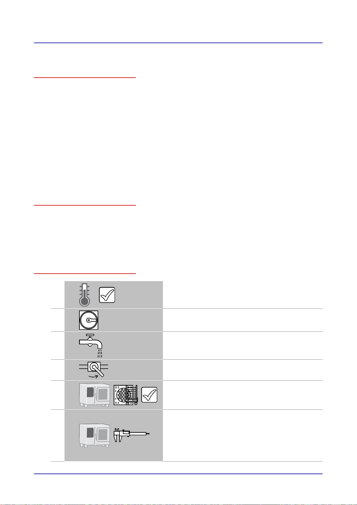
7 Placing into operation
7.2 Procedure for Placing the Unit into Operation
Checks before placing the unit into operation
Before putting the combi oven into operation, check whether the prerequisites below are being met:
■
The unit and the accessories being used do not have any obvious damage.
■
The unit has been set up in such a way that it will not shift or topple over; the requirements con‐
cerning the location and the unit's surroundings are met (please refer to the
■
Protective films, cardboard, securing devices for shipping, etc., have been removed completely.
■
There is nothing being stored inside the oven cavity and there is nothing inside the oven cavity oth‐
er than required cooking accessories (food containers, for example).
■
The unit has been installed as per the specifications in the 'Installation' on page 42 section.
■
The supply lines installed for electrical power, water, wastewater, and cleaning agents do not have
any obvious damage, have a secure fit, are not dripping anywhere, and appear to be safe and fully
functional after a visual inspection.
■
The unit has been subjected to an individual electric inspection (see below).
■
All safety guards and devices are in their intended place and are working properly.
■
All warning labels are at their intended location.
■
The unit and the accessories being used must have been cleaned properly.
Do not place the unit into operation unless all specified prerequisites are met.
Individual electric inspection
'Setup' on page 33).
An individual electric inspection includes the following three steps:
■
Inspection: Visual inspection for damage and improper use
■
Measurement: Measurements performed as per generally accepted standards and practices
(equipment grounding conductor resistance, insulation resistance, equipment grounding conductor
current / leakage current)
■
Testing: Functional test
The individual electric inspection must be repeated at regular intervals as required by law.
Preparing to place the unit into operation
1.
Bring the ambient temperature to the permissible operat‐
ing temperature.
2.
3.
4.
5.
Turn on the circuit breaker.
Open the water supply.
Open the gas flow (in the case of gas units).
Check to make sure that the following are installed prop‐
erly in the right position:
■
Suction panel
■
Loading trolley
6.
Measure the door gap at the front of the unit as indicated
in 'Measuring Unit Gaps' on page
If the measured gap falls outside the corresponding toler‐
ance range, or if the unit door's upper edge is not aligned
with the unit case's upper edge, the unit door will need to
be adjusted.
Adjust the door as indicated in the service documentation
or contact the manufacturer.
74:
Installation Manual 71
Page 72
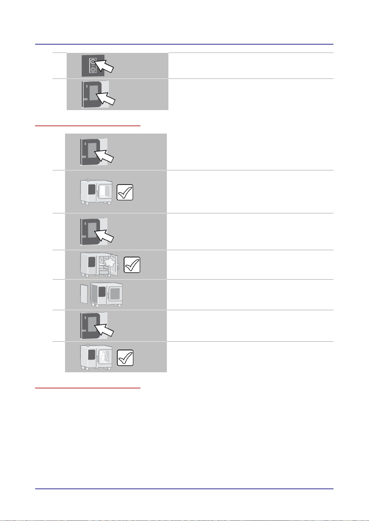
7 Placing into operation
7.
8.
Placing the unit into operation
1.
2.
3.
4.
Turn the combi oven on.
Set the following:
■
Date
■
Time
■
Language
Start the cooking sequence using the following cooking
data:
■
'Combi-steam' operating mode
■
300
°F
■
10 minutes
Check the following:
■
Is the oven light on?
■
Is the fan wheel running?
■
Are there any leaks in the wastewater and supply water
systems?
■
Is the temperature increasing inside the oven cavity?
Start the cooking sequence using the following cooking
data:
■
'Steam' operating mode
■
210 °F
■
10 minutes
Check whether steam is being produced inside the oven
cavity
(carefully open the unit door).
5.
Use the pressure regulator to adjust the pressure gauge in
the steam generation system's water supply:
■
[psi] 21.76
■
[bar] 1.5
6.
Start the fully automatic cleaning process with the clean‐
ing profile for light soiling.
7.
Check that the cleaning sequence is completed without
any error messages.
Briefing the user
Brief the user on all safety-relevant functions, mechanisms, and devices. Show the user how to oper‐
ate the unit and fill out the checklist enclosed with the unit.
Installation Manual 72
Page 73

7 Placing into operation
Warranty information
Warranty claims involving your combi oven will only be honored if the unit has been installed by a
qualified service technician from an authorized service company as per the instructions in this installa‐
tion manual. Please note that warranty claims will only be honored if the manufacturer has a copy of
the fully completed checklist from the installation manual.
The warranty will be void if there is any damage that can be traced back to improper setup, installa‐
tion, use, cleaning, use of cleaning agents, maintenance, repair, or descaling.
In order to get a two-year extended warranty for spare parts, the unit needs to be registered on the
manufacturer's website (www.convotherm.de) after installation.
Installation Manual 73
Page 74
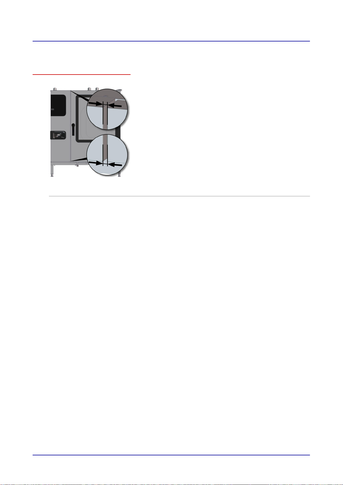
7 Placing into operation
7.3 Measuring unit gaps
Measuring unit gaps
The unit gaps' measured widths must fall within the following tolerance ranges:
Designation Measuring condition Tolerance range
Door gap at the front of the unit The unit door must be closed.
2
/5" ± 1/25"
(0.4" ± 0.04")
If the door gap falls outside the tolerance range, please contact Customer Service.
Installation Manual 74
Page 75

8 Removing from Service and Disposal
8 Removing from Service and Disposal
8.1 Removing from Service and Disposal
Rules for working safely and responsibly when removing the unit from service
Avoid endangering yourself and others by following the rules below:
■
Always keep the kitchen floor dry in order to reduce the risk of accidents occurring.
■
Before disposing of the unit, close the combi oven door and remove the door handle.
■
Cleaning agents must be disposed of as instructed in the canisters in order to avoid damaging the
environment.
Prerequisites
Check the following before removing the unit from service:
■
The unit has been de-energized.
■
The gas has been shut off.
■
The water supply has been shut off.
Removing from service
To remove your unit from service, undo all setup and installation work step-by-step in opposite order
(please refer to the 'Installation' on page
42, 'Transportation' on page 31, and 'Setup' on page 33 sec‐
tions).
Do not move the unit before disconnecting all of its connections.
The following work must be done properly in order to remove the unit from service:
■
Removing the unit's water connection
■
Removing the unit's drain connection
■
Removing or disconnecting the electrical connections
■
Removing the unit's gas connection
■
Removing the exhaust extraction system
■
Removing the door lock
■
Removing the cleaning agent and rinse aid connections
■
Properly disposing of all cleaning agents as indicated in the corresponding EC safety data sheets
and the cleaning agent containers
■
Removing the grease collection canister
■
Disposing of pumped-out used grease in compliance with the relevant country-specific laws and
regulations, as well as in compliance with all applicable rules and regulations set forth by the rele‐
vant local disposal companies and authorities
Disposal
Contact the manufacturer in order to arrange for your unit to be disposed of in an environmentally re‐
sponsible manner. The manufacturer has an ISO 14001:2004-certified environmental management
system and will dispose of your old unit in compliance with all applicable environmental protection reg‐
ulations.
Installation Manual 75
Page 76

9 Technical data
9 Technical data
9.1 Dimensions and weights
C4 EB/ES dimensions
Unit with packaging
Width [in] 56.3 46.7 56.3
Height [in] 65.2 85.0 85.0
Depth [in] 46.9 39.0 46.9
Unit without packaging
Width of units featuring a right-hinged door [in] 44.69 35.04 44.69
Width of units with a disappearing door, incl. guide bracket [in] 46.54 36.89 46.54
Height [in] 55.35 76.46 76.46
Depth when the unit door is closed [in] 40.16 32.28 40.16
Safety clearances
Rear [in] 2 2 2
Right-hand side (units featuring a right-hinged door) [in] 2 2 2
Right-hand side (units featuring a disappearing door) [in] 2 2 2
Left-hand side (larger gap recommended for servicing) [in] 2 2 2
Above (for ventilation) [in] 20 20 20
12.20 20.10 20.20
C4 GB/GS dimensions
Unit with packaging
Width [in] 56.3 46.7 56.3
Height [in] 65.2 85.0 85.0
Depth [in] 46.9 39.0 46.9
Unit without
Width of units featuring a right-hinged door [in] 44.69 35.04 44.69
Width of units with a disappearing door, incl. guide bracket [in] 49.10 39.45 49.10
Height [in] 55.35 76.46 76.46
Depth when the unit door is closed [in] 40.16 32.28 40.16
Safety clearances
Rear [in] 2 2 2
Right-hand side (units featuring a right-hinged door) [in] 2 2 2
Right-hand side (units featuring a disappearing door) [in] 2 2 2
Left-hand side (larger gap recommended for servicing) [in] 2 2 2
Above (for ventilation) [in] 39 39 39
packaging
12.20 20.10 20.20
Installation Manual 76
Page 77

9 Technical data
C4 EB weights
Weight without packaging
without ConvoClean / ConvoClean+
- Right-hinged door [lbs] 558 593 778
- Disappearing door [lbs] 582 637 822
with ConvoClean / ConvoClean+
- Right-hinged door [lbs] 571 608 794
- Disappearing door [lbs] 595 653 838
Packaging weight
Packaging weight [lbs] 99 88 106
C4 ES weights
Weight without packaging
without ConvoClean / ConvoClean+
- Right-hinged door [lbs] 525 560 739
- Disappearing door [lbs] 549 604 783
with ConvoClean / ConvoClean+
- Right-hinged door [lbs] 538 575 754
- Disappearing door [lbs] 562 619 798
Packaging weight
Packaging weight [lbs] 99 88 106
12.20 20.10 20.20
12.20 20.10 20.20
C4 GB weights
Weight without packaging
without ConvoClean / ConvoClean+
- Right-hinged door [lbs] 639 628 825
- Disappearing door [lbs] 677 672 869
with ConvoClean / ConvoClean+
- Right-hinged door [lbs] 653 644 840
- Disappearing door [lbs] 664 688 884
Packaging weight
Packaging weight [lbs] 99 88 106
12.20 20.10 20.20
Installation Manual 77
Page 78

9 Technical data
C4 GS weights
12.20 20.10 20.20
Weight without packaging
without ConvoClean / ConvoClean+
- Right-hinged door [lbs] 595 591 785
- Disappearing door [lbs] 619 635 844
with ConvoClean / ConvoClean+
- Right-hinged door [lbs] 608 606 800
- Disappearing door [lbs] 633 650 829
Packaging weight
Packaging weight [lbs] 99 88 106
9.2 Maximum permissible loading weight
C4 EB/ES/GB/GS
The total weight placed on the rack levels must not exceed the combi oven's maximum permissible
loading weight:
12.20 20.10 20.20
Maximum load weight
Per combi oven [lbs] 265 220 397
Per shelf [lbs] 33 33 33
Installation Manual 78
Page 79

9 Technical data
9.3 EB/ES Electrical Supply
C4 EB (three-phase VFD)
3~ 208/240V 60Hz (3/PE)
Rated power consumption [kW] 27.4 /
Hot air output [kW] 27.0 /
Steam output [kW] 25.6 /
Motor output [kW] 0.35 0.7 0.7
Rated current [A] 76.1 /
Recommended supply connection
Field wire gauge AWG 3/2 2 2/0 3/0
Ground wire gauge AWG 6 6 4
Conductor insulation rating 194 °F 194 °F 194 °F
Ground fault circuit interrupter (GFCI) Class A A A
12.20 20.10 20.20
36.3
35.9
34.1
87.5
31.3 /
41.6
30.9 /
41.2
25.6 /
34.1
87.1 /
100.1
54.4 /
72.3
54.0 /
71.9
32.6 /
43.4
151.1 /
174.1
C4 ES (three-phase VFD)
3~ 208/240V 60Hz (3/PE)
Rated power consumption [kW] 27.4 /
Hot air output [kW] 27.0 /
Motor output [kW] 0.35 0.7 0.7
Rated current [A] 76.1 /
Recommended supply connection
Field wire gauge AWG 3/2 2 2/0 3/0
Ground wire gauge AWG 6 6 4
Conductor insulation rating 194 °F 194 °F 194 °F
Ground fault circuit interrupter (GFCI) Class A A A
12.20 20.10 20.20
36.3
35.9
87.5
31.3 /
41.6
30.9 /
41.2
87.1 /
100.1
54.4 /
72.3
54.0 /
71.9
151.1 /
174.1
Installation Manual 79
Page 80

9 Technical data
C4 EB (three-phase VFD)
3~ 440/480V 60 Hz
Rated power consumption [kW] 28.2 /
Hot air output [kW] 27.8 /
Steam output [kW] 26.3 /
Motor output [kW] 0.35 0.7 / 0.7 0.7 / 0.7
Rated current [A] 37.0 /
Recommended supply connection
Field wire gauge AWG 8/6 6 4/3
Ground wire gauge AWG 10/8 8 6
Conductor insulation rating 194 °F 194 °F 194 °F
Ground fault circuit interrupter (GFCI) Class *) *) *)
*) Certified in conformity with UL 943 and under consideration of the installation requirements in NEC NFPA70
12.20 20.10 20.20
33.4
33.0
31.3
40.3
32.6 /
38.6
31.8 /
37.8
26.3 /
31.3
42.8 /
46.5
56.3 /
66.8
55.5 /
66.1
33.6 /
39.9
73.9 /
80.5
C4 ES (three-phase VFD)
3~ 440/480V 60 Hz
Rated power consumption [kW] 28.2 /
Hot air output [kW] 27.8 /
Motor output [kW] 0.35 0.7 / 0.7 0.7 / 0.7
Rated current [A] 37.0 /
Recommended supply connection
Field wire gauge AWG 8/6 6 4/3
Ground wire gauge AWG 10/8 8 6
Conductor insulation rating 194 °F 194 °F 194 °F
Ground fault circuit interrupter (GFCI) Class *) *) *)
*) Certified in conformity with UL 943 and under consideration of the installation requirements in NEC NFPA70
C4 EB (three-phase VFD)
3~ 208V 60Hz (3/PE)
Rated power consumption [kW] 27.4 31.3 54.4
Hot air output [kW] 27.0 30.9 54.0
Steam output [kW] 25.6 25.6 32.6
Motor output [kW] 0.35 0.7 0.7
Rated current [A] 76.1 87.1 151.1
Recommended supply connection
Field wire gauge AWG 3 2 2/0
Ground wire gauge AWG 6 6 4
Ground fault circuit interrupter (GFCI) Class A A A
12.20 20.10 20.20
33.4
33.0
40.3
32.6 /
38.6
31.8 /
37.8
42.8 /
46.5
56.3 /
66.8
55.5 /
66.1
73.9 /
80.5
12.20 20.10 20.20
Installation Manual 80
Page 81

9 Technical data
C4 ES (three-phase VFD)
3~ 208V 60Hz (3/PE)
Rated power consumption [kW] 27.4 31.3 54.4
Hot air output [kW] 27.0 30.9 54.0
Motor output [kW] 0.35 0.7 0.7
Rated current [A] 76.1 87.1 151.1
Recommended supply connection
Field wire gauge AWG 3 2 2/0
Ground wire gauge AWG 6 6 4
Ground fault circuit interrupter (GFCI) Class A A A
C4 EB (three-phase VFD)
3~ 240V 60Hz (3/PE)
Rated power consumption [kW] 36.3 41.6 72.3
Hot air output [kW] 35.9 41.2 71.9
Steam output [kW] 34.1 34.1 43.4
Motor output [kW] 0.35 0.7 0.7
Rated current [A] 87.5 100.1 174.1
Recommended supply connection
Field wire gauge AWG 2 2 3/0
Ground wire gauge AWG 6 6 4
Ground fault circuit interrupter (GFCI) Class A A A
12.20 20.10 20.20
12.20 20.10 20.20
C4 ES (three-phase VFD)
3~ 240V 60Hz (3/PE)
Rated power consumption [kW] 36.3 41.6 72.3
Hot air output [kW] 35.9 41.2 71.9
Motor output [kW] 0.35 0.7 0.7
Rated current [A] 87.5 100.1 174.1
Recommended supply connection
Field wire gauge AWG 2 2 3/0
Ground wire gauge AWG 6 6 4
Ground fault circuit interrupter (GFCI) Class A A A
12.20 20.10 20.20
Installation Manual 81
Page 82

9 Technical data
9.4 GB/GS Electrical Supply
C4 GB (single-phase VFD)
1N~ 120V 60 Hz
Rated power consumption [kW] 0.6 1.1 1.1
Hot air output [kW] 0.1 0.2 0.2
Steam output [kW] 0.1 0.1 0.1
Motor output [kW] 0.35 0.7 0.7
Rated current [A] 7.5 8.3 10.6
Recommended supply connection
Field wire gauge AWG 14 14 14
Ground wire gauge AWG 14 14 14
Conductor insulation rating 194 °F 194 °F 194 °F
Ground fault circuit interrupter (GFCI) Class A A A
C4 GS (single-phase VFD)
12.20 20.10 20.20
12.20 20.10 20.20
1N~ 120V 60 Hz
Rated power consumption [kW] 0.5 1.0 1.0
Hot air output [kW] 0.1 0.2 0.2
Motor output [kW] 0.35 0.7 0.7
Rated current [A] 7.5 8.3 10.6
Residual current [mA] - - 4.8
Recommended supply connection
Field wire gauge AWG 14 14 14
Ground wire gauge AWG 14 14 14
Conductor insulation rating 194 °F 194 °F 194 °F
Ground fault circuit interrupter (GFCI) Class A A A
Installation Manual 82
Page 83

9 Technical data
9.5 Gas Characteristic Values for Natural Gas (USA), Propane (USA)
C4 GB/GS
Gas type
Operating materials
Natural gas, propane x x
Gas supply parameters
Gas line connection for unit sizes 12.20,
20.10, and 20.20
Supply flow pressure [inch WC] 7 (5.5 to 14) 11 (11 to 14)
Exhaust extraction system
Air ventilation system with safety shutdown
function
Exhaust gas parameters
Exhaust gas reading CO
Exhaust gas reading CO [ppm] < 500 < 500
2
[%] 9.4 - 11.1 10.5 - 12.5
Natural Gas (USA) Propane (USA)
3/4" NPT 3/4" NPT
Mandatory Mandatory
Installation Manual 83
Page 84

9 Technical data
9.6 Heat loss
C4 EB
When the unit door is closed
Latent [BTU/h] 6600 6500 10500
Sensible [BTU/h] 7400 8500 13400
C4 ES
When the unit door is closed
Latent [BTU/h] 6600 6500 11500
Sensible [BTU/h] 7400 8500 13400
C4 GB/GS
When the unit door is closed
Latent [BTU/h] 7800 6700 11600
Sensible [BTU/h] 10500 10500 14600
12.20 20.10 20.20
12.20 20.10 20.20
12.20 20.10 20.20
9.7 Water connections
C4 EB/ES/GB/GS
Water supply (cold only)
Shut-off device Adequate backflow preventer
Water supply Two 3/4'' inner diameter GHT-M (gar‐
Flow pressure [psi] / [bar] 22 - 87 psi / 1.5 - 6 bar
Pressure gauge in water supply [psi] / [bar] 21.76 psi / 1.5 bar
Water drain
Version Naturally ventilated pipe to open pan or
Type DN 2" inside diameter (comes elbow-sha‐
Drain temperature [°F] / [ºC] max. 140°F / 60°C
Slope for drain pipe min. 3.5% (2°)
Safety overflow [inch] 3.2" x 1"
den hose adapter).
The unit is designed for a permanent
hookup to the water supply that uses a
connecting hose with a minimum diam‐
eter of 1/2"
drain/channel
ped as standard)
Installation Manual 84
Page 85

9 Technical data
9.8 Water quality
C4 EB/GB
Water connection (A) for boiler; water connection (B) for cleaning, recoil hand shower
General water quality Drinking water
Hardness [ppm] 70 - 360 ppm (4 - 21 gpg)
TDS (total dissolved solids) [ppm] 70 - 360
Total alkalinity [ppm] 50 - 100
Water connections (A) and (B)
Temperature [°F] max. 104
pH value 6.5 - 8.5
Cl- (chloride)
CI2 (free chlorine) [ppm] max. 0.2
2-
SO
(sulfate)
4
Fe (iron) [ppm] max. 0.1
SiO2 (silicate) [ppm] max. 13
NH2Cl (monochloramine) [ppm] max. 0.2
[ppm] max. 60
[ppm] max. 150
C4 ES/GS
Water connection (A) for water injection
General water quality Drinking water
Hardness [ppm] 70 - 125 ppm (4 - 7 gpg)
TDS (total dissolved solids) [ppm] 70 - 125
Total alkalinity [ppm] 50 - 100
Water connection (B) for cleaning, recoil hand shower
General water quality Drinking water
Hardness [ppm] 70 - 360 ppm (4 - 21 gpg)
TDS (total dissolved solids) [ppm] 70 - 360
Total alkalinity [ppm] 50 - 100
Water connections (A) and (B)
Temperature [°F] max. 104
pH value 6.5 - 8.5
Cl- (chloride)
CI2 (free chlorine) [ppm] max. 0.2
SO
Fe (iron) [ppm] max. 0.1
SiO2 (silicate) [ppm] max. 13
NH2Cl (monochloramine) [ppm] max. 0.2
2-
(sulfate)
4
[ppm] max. 60
[ppm] max. 150
Installation Manual 85
Page 86

9 Technical data
9.9 Boiler
C4 EB/GB
6.10 6.20 10.10 10.20 12.20 20.10 20.20
Steam output [gph] 3.80 7.58 7.58 11.12 13.18 11.36 16.80
Contents [gal] 1.00 1.59 1.59 2.11 2.88 2.17 2.88
9.10 Water consumption during cooking
C4 EB/GB
Hard and soft water
Average consumption without cleaning [gph] 2.8 2.6 3.5
Maximum possible water flow rate [gpm] 4.0 4.0 4.0
C4 ES/GS
12.20 20.10 20.20
12.20 20.10 20.20
Hard and soft water
Average consumption without cleaning [gph] 3.5 3.2 4.7
Maximum possible water flow rate [gpm] 4.0 4.0 4.0
Soft water (water treatment system sizing)
Average consumption without cleaning [gph] 2.3 2.1 3.1
Maximum possible water flow rate [gpm] 0.2 0.2 0.2
Installation Manual 86
Page 87

9 Technical data
9.11 Water consumption during cooking and cleaning
C4 EB/GB
Hard and soft water
Average water consumption with cleaning [gph] 3.8 3.6 4.5
C4 ES/GS
Hard and soft water
Average water consumption with cleaning [gph] 4.5 4.2 5.7
12.20 20.10 20.20
12.20 20.10 20.20
Installation Manual 87
Page 88
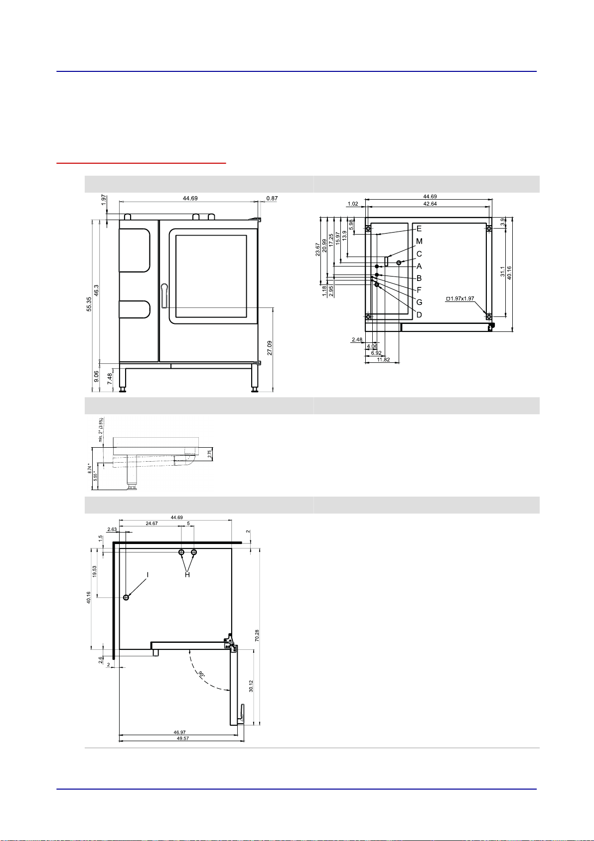
10 Connection drawings
10 Connection drawings
10.1
Convotherm 4 12.20 Electrical units
C4 12.20 dimensions and connection points (right-hinged unit door)
Front view Connection points, unit floor
Drain connection detail
* The distance depends on how much
the feet are extended (max. +0.984")
View from above with wall clearances Key
A Water connections (for boiler or water injec‐
B Water connections (for cleaning, recoil
C Drain connection (2" internal diameter)
D Electrical connection
E Bonding
F Rinse-aid connection (optional)
G Cleaning-agent connection (optional)
H Air vent (2" internal diameter)
I Dry air intake (2" internal diameter)
M Safety overflow 3.2" x 1"
tion)
hand shower)
Installation Manual 88
Page 89
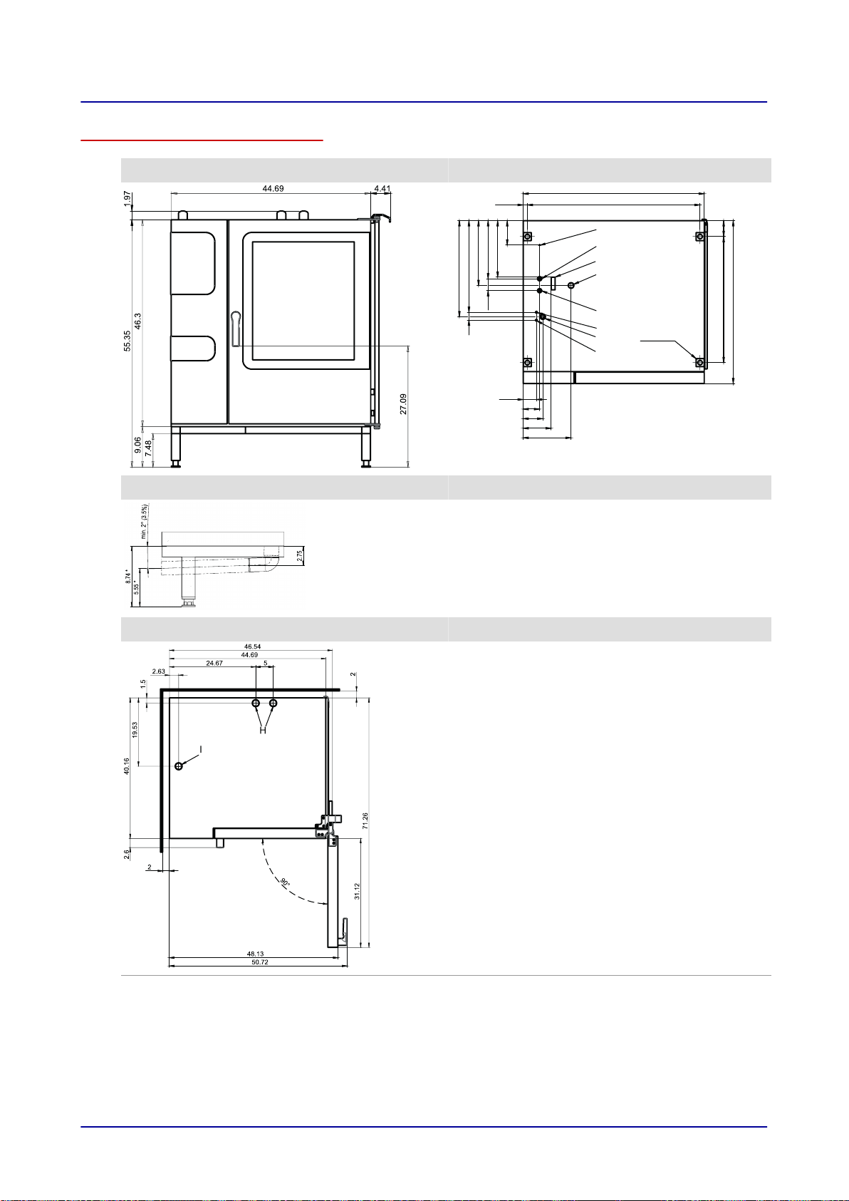
1.02
42.64
3.9
31.
1
3.27
4.06
6.92
11.82
13.9
15.97
14.3
22.57
2.95
23.67
40.16
44.69
5.98
2
5
[
A
B
M
C
D
F
G
E
10 Connection drawings
C4 12.20 dimensions and connection points (disappearing door)
Front view Connection points, unit floor
Drain connection detail
* The distance depends on how much
the feet are extended (max. +0.984")
View from above with wall clearances Key
A Water connections (for boiler or water injec‐
tion)
B Water connections (for cleaning, recoil
hand shower)
C Drain connection (2" internal diameter)
D Electrical connection
E Bonding
F Rinse-aid connection (optional)
G Cleaning-agent connection (optional)
H Air vent (2" internal diameter)
I Dry air intake (2" internal diameter)
M Safety overflow 3.2" x 1"
Installation Manual 89
Page 90
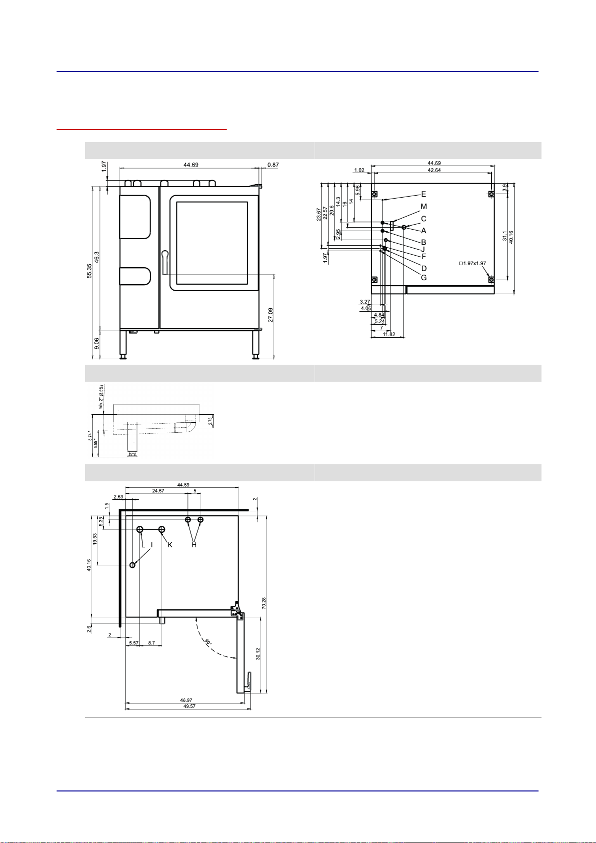
10 Connection drawings
10.2 Convotherm 4 12.20 Gas Unit with Boiler
C4 12.20 dimensions and connection points (right-hinged unit door)
Front view Connection points, unit floor
Drain connection detail
* The distance depends on how much
the feet are extended (max. +0.984")
View from above with wall clearances Key
A Water connections (for boiler or water injec‐
B Water connections (for cleaning, recoil
C Drain connection (2" internal diameter)
D Electrical connection
E Bonding
F Rinse-aid connection (optional)
G Cleaning-agent connection (optional)
H Air vent (2" internal diameter)
I Dry air intake (2" internal diameter)
J Gas connection
K Convection burner exhaust outlet (2.37" in‐
L Boiler burner exhaust outlet (2.37" internal
M Safety overflow 3.2" x 1"
tion)
hand shower)
ternal diameter)
diameter)
Installation Manual 90
Page 91
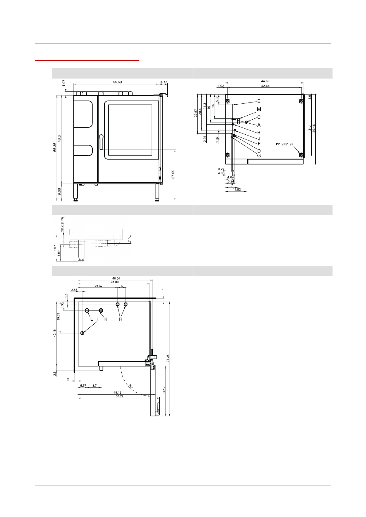
10 Connection drawings
C4 12.20 dimensions and connection points (disappearing door)
Front view Connection points, unit floor
Drain connection detail
* The distance depends on how much
the feet are extended (max. +0.984")
View from above with wall clearances Key
A Water connections (for boiler or water injec‐
B Water connections (for cleaning, recoil
C Drain connection (2" internal diameter)
D Electrical connection
E Bonding
F Rinse-aid connection (optional)
G Cleaning-agent connection (optional)
H Air vent (2" internal diameter)
I Dry air intake (2" internal diameter)
J Gas connection
K Convection burner exhaust outlet (2.37" in‐
L Boiler burner exhaust outlet (2.37" internal
M Safety overflow 3.2" x 1"
tion)
hand shower)
ternal diameter)
diameter)
Installation Manual 91
Page 92
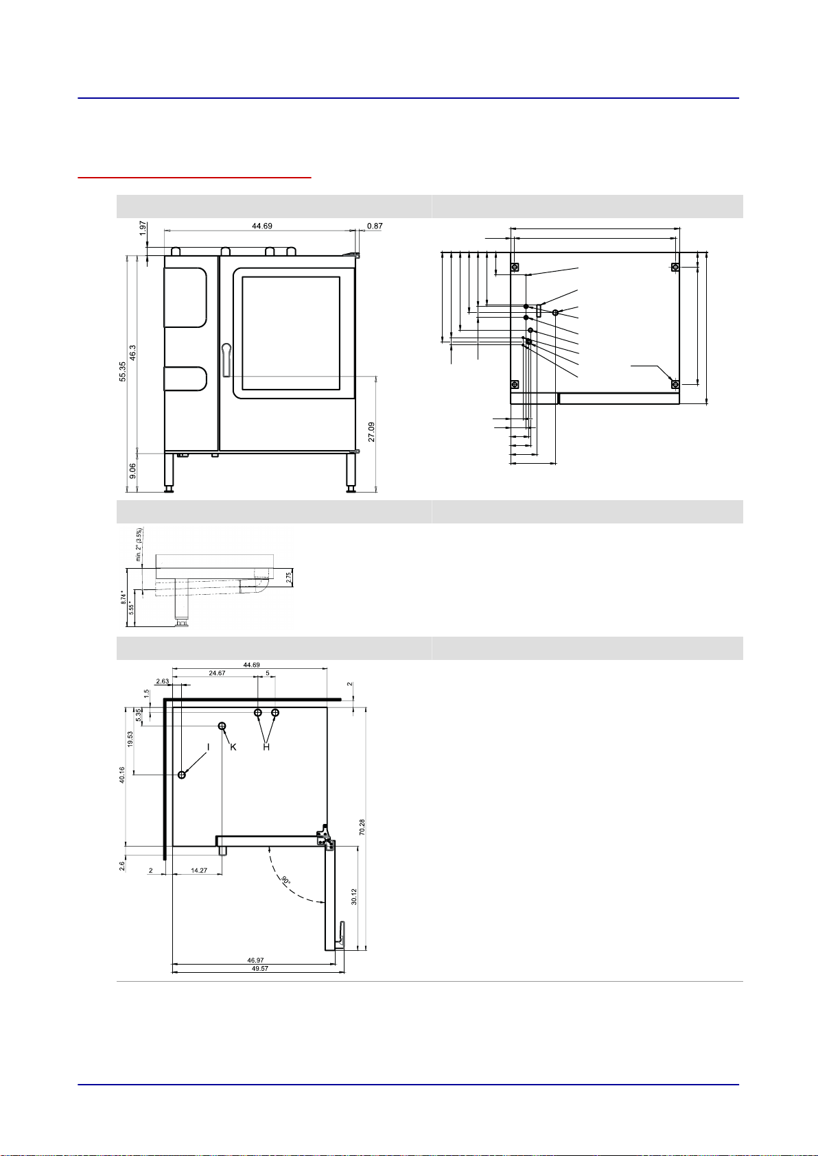
1.02
42.64
3.9
3
1.1
3.27
4.06
6.92
11.82
13.9
15.97
22.57
2.95
24
40.16
44.69
5.98
14.3
1.97
5.24
20.6
4.84
A
B
M
C
D
F
G
E
J
5.91x1.97
10 Connection drawings
10.3 Convotherm 4 12.20 Gas Unit with Sprayer
C4 12.20 dimensions and connection points (right-hinged unit door)
Front view Connection points, unit floor
Drain connection detail
* The distance depends on how much
the feet are extended (max. +0.984")
View from above with wall clearances Key
A Water connections (for boiler or water injec‐
tion)
B Water connections (for cleaning, recoil
hand shower)
C Drain connection (2" internal diameter)
D Electrical connection
E Bonding
F Rinse-aid connection (optional)
G Cleaning-agent connection (optional)
H Air vent (2" internal diameter)
I Dry air intake (2" internal diameter)
J Gas connection
K Exhaust outlet (2.37" internal diameter)
M Safety overflow 3.2" x 1"
Installation Manual 92
Page 93
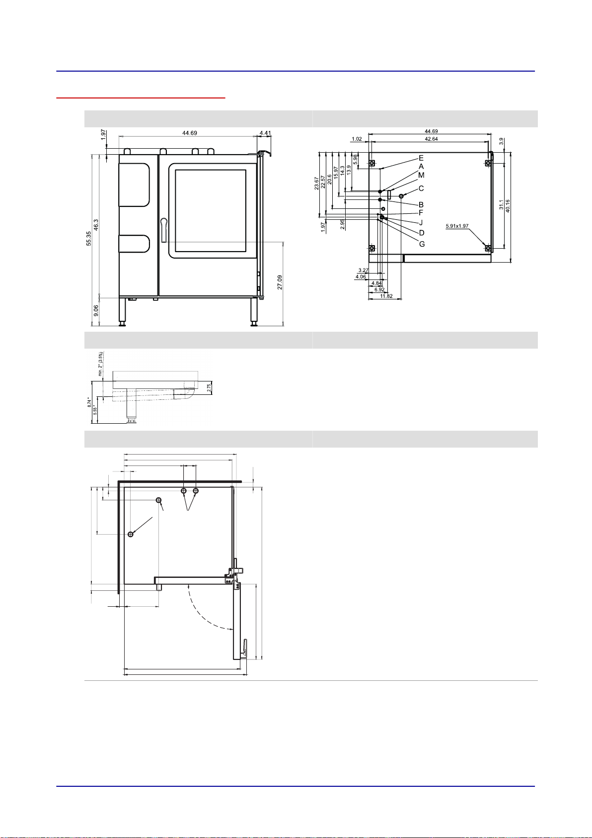
2
2
24.67
5
1.5
31.12
71.28
46.54
40.16
2.6
48.13
50.72
19.53
2.63
44.69
90°
5.35
14.27
H
I
K
10 Connection drawings
C4 12.20 dimensions and connection points (disappearing door)
Front view Connection points, unit floor
Drain connection detail
* The distance depends on how much
the feet are extended (max. +0.984")
View from above with wall clearances Key
A Water connections (for boiler or water injec‐
tion)
B Water connections (for cleaning, recoil
hand shower)
C Drain connection (2" internal diameter)
D Electrical connection
E Bonding
F Rinse-aid connection (optional)
G Cleaning-agent connection (optional)
H Air vent (2" internal diameter)
I Dry air intake (2" internal diameter)
J Gas connection
K Exhaust outlet (2.37" internal diameter)
M Safety overflow 3.2" x 1"
Installation Manual 93
Page 94
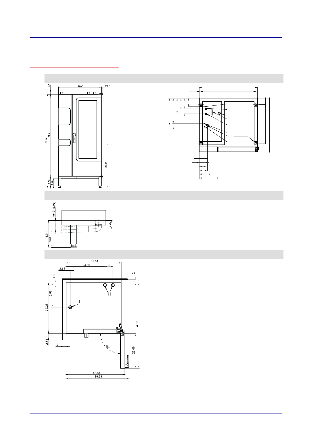
32.28
35.04
1.02
32.99
3.9
23
.23
7.02
9.08
6.43
15.28
16.27
2.95
1.97
3.27
7.1
12
5.16
4.84
4.06
3
[
A
B
M
C
F
G
D
E
10 Connection drawings
10.4 Convotherm 4 20.10 Electrical units
C4 20.10 dimensions and connection points (right-hinged unit door)
Front view Connection points, unit floor
Drain connection detail
* The distance depends on how much
the feet are extended (max. +0.984")
View from above with wall clearances Key
A Water connections (for boiler or water injec‐
B Water connections (for cleaning, recoil
C Drain connection (2" internal diameter)
D Electrical connection
E Bonding
F Rinse-aid connection (optional)
G Cleaning-agent connection (optional)
H Air vent (2" internal diameter)
I Dry air intake (2" internal diameter)
M Safety overflow 3.2" x 1"
tion)
hand shower)
Installation Manual 94
Page 95
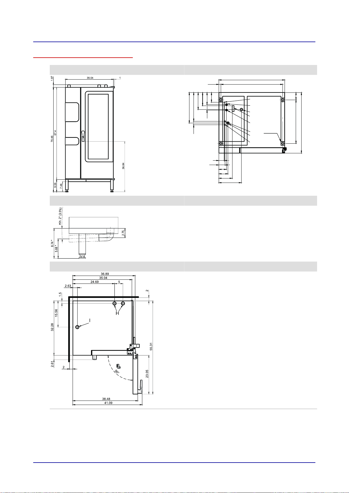
32.28
35.04
1.02
32.99
3.9
23
.23
7.02
9.08
6.43
15.28
16.27
2.95
1.97
3.27
7.1
12
5.16
4.06
4.84
3
1.97x1.97
A
B
M
C
F
G
D
E
10 Connection drawings
C4 20.10 dimensions and connection points (disappearing door)
Front view Connection points, unit floor
Drain connection detail
* The distance depends on how much
the feet are extended (max. +0.984")
View from above with wall clearances Key
A Water connections (for boiler or water injec‐
B Water connections (for cleaning, recoil
C Drain connection (2" internal diameter)
D Electrical connection
E Bonding
F Rinse-aid connection (optional)
G Cleaning-agent connection (optional)
H Air vent (2" internal diameter)
I Dry air intake (2" internal diameter)
M Safety overflow 3.2" x 1"
tion)
hand shower)
Installation Manual 95
Page 96
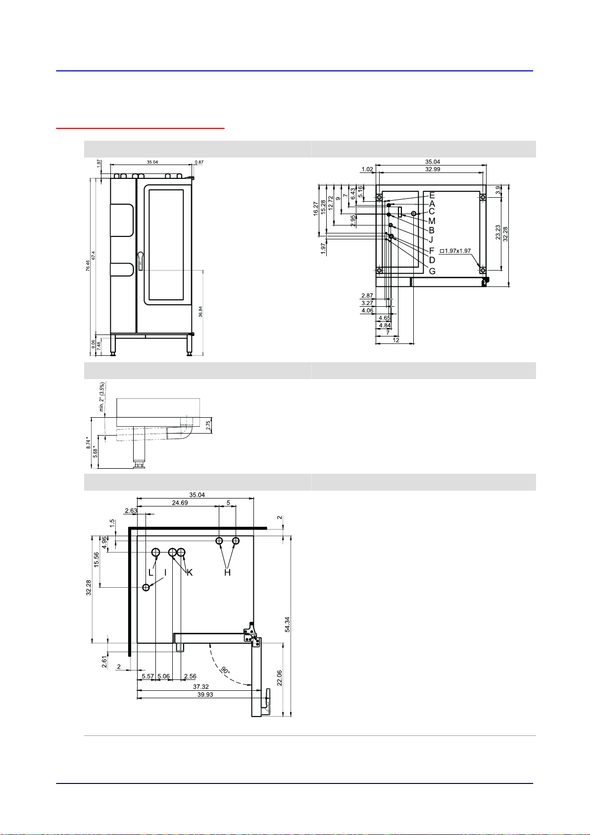
10 Connection drawings
10.5 Convotherm 4 20.10 Gas Unit with Boiler
C4 20.10 dimensions and connection points (right-hinged unit door)
Front view Connection points, unit floor
Drain connection detail
* The distance depends on how much
the feet are extended (max. +0.984")
View from above with wall clearances Key
A Water connections (for boiler or water injec‐
B Water connections (for cleaning, recoil
C Drain connection (2" internal diameter)
D Electrical connection
E Bonding
F Rinse-aid connection (optional)
G Cleaning-agent connection (optional)
H Air vent (2" internal diameter)
I Dry air intake (2" internal diameter)
J Gas connection
K Convection burner exhaust outlet (2" inter‐
L Boiler burner exhaust outlet (2.37" internal
M Safety overflow 3.2" x 1"
tion)
hand shower)
nal diameter)
diameter)
Installation Manual 96
Page 97
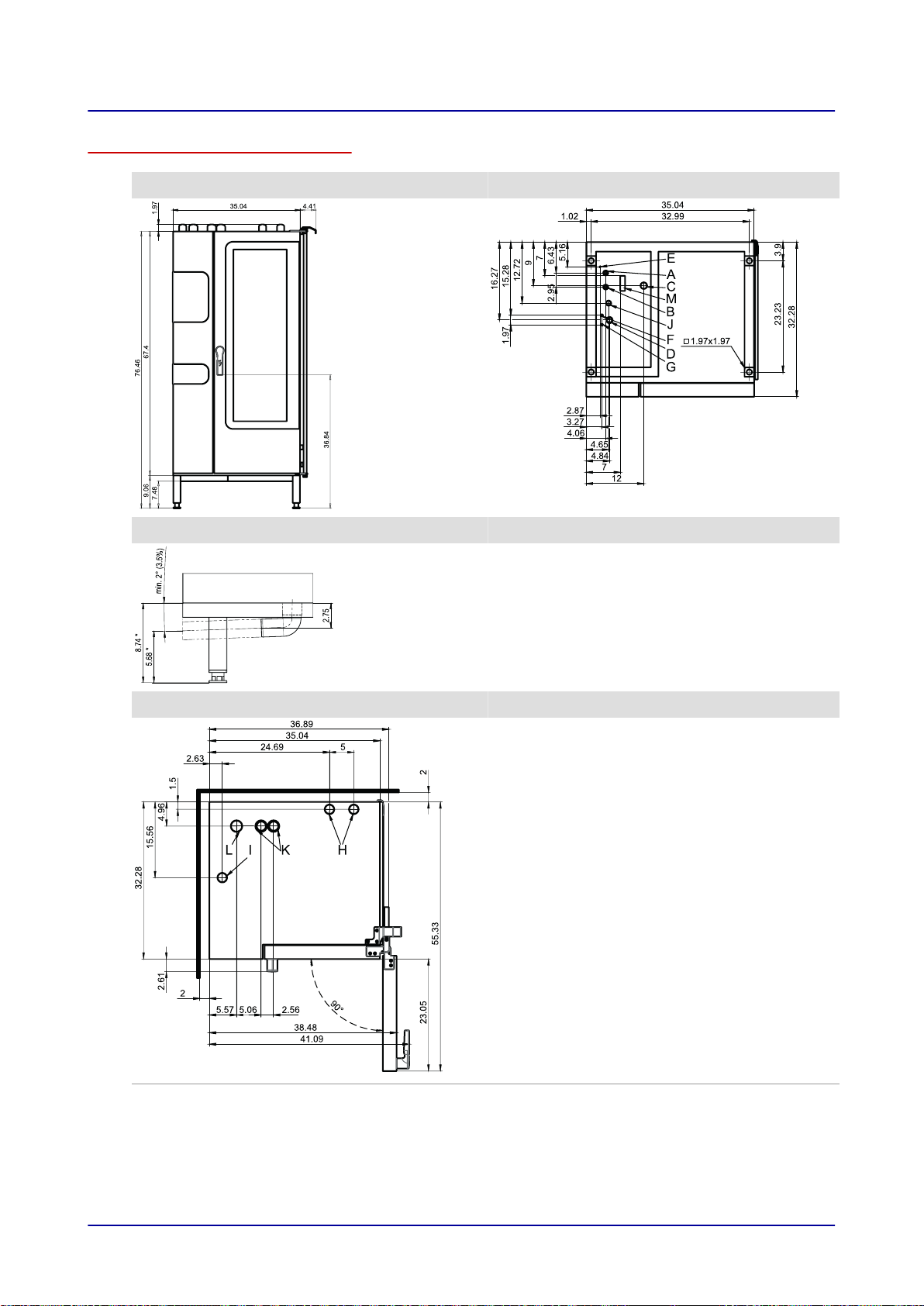
10 Connection drawings
C4 20.10 dimensions and connection points (disappearing door)
Front view Connection points, unit floor
Drain connection detail
* The distance depends on how much
the feet are extended (max. +0.984")
View from above with wall clearances Key
A Water connections (for boiler or water injec‐
B Water connections (for cleaning, recoil
C Drain connection (2" internal diameter)
D Electrical connection
E Bonding
F Rinse-aid connection (optional)
G Cleaning-agent connection (optional)
H Air vent (2" internal diameter)
I Dry air intake (2" internal diameter)
J Gas connection
K Convection burner exhaust outlet (2" inter‐
L Boiler burner exhaust outlet (2.37" internal
M Safety overflow 3.2" x 1"
tion)
hand shower)
nal diameter)
diameter)
Installation Manual 97
Page 98
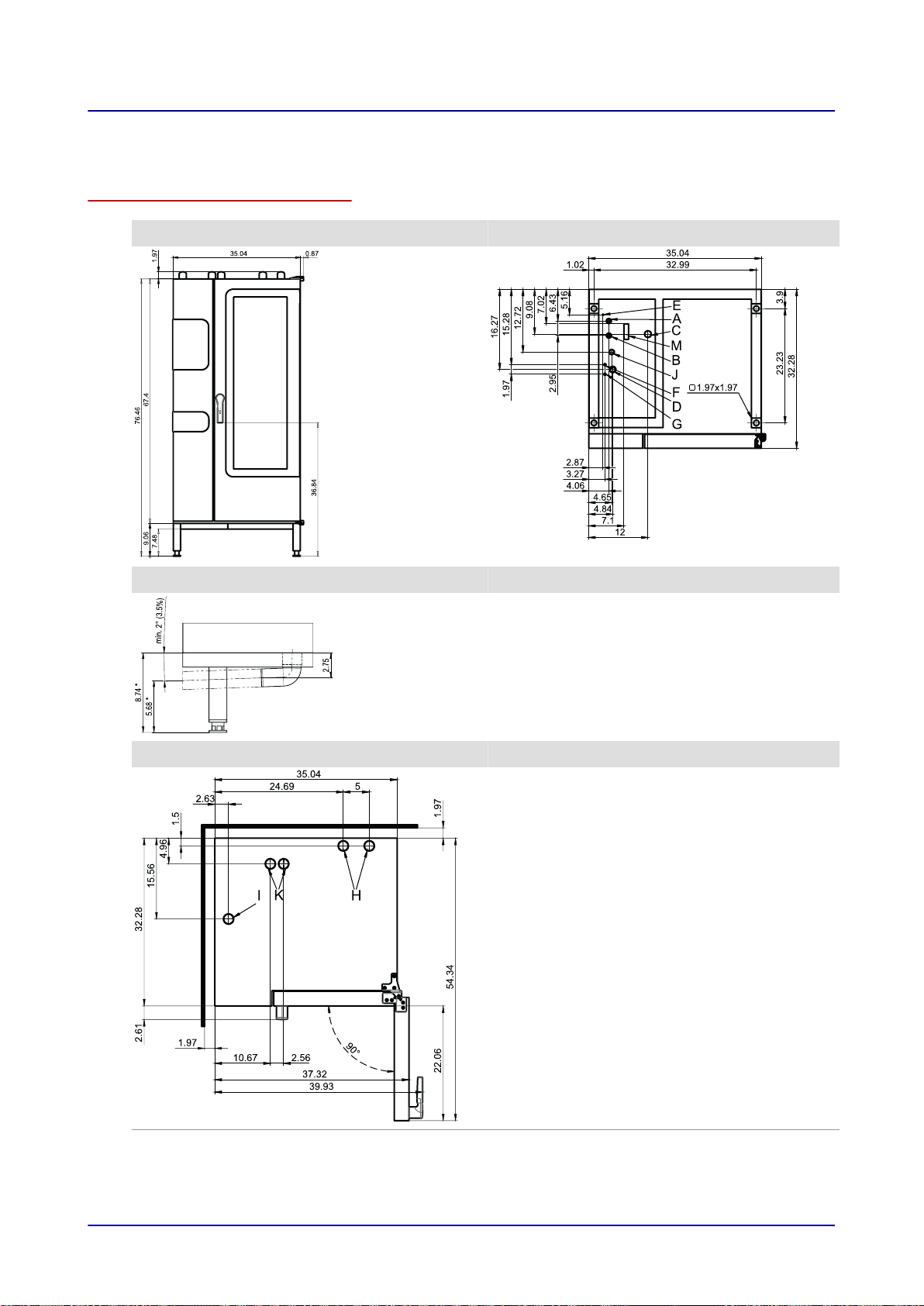
10 Connection drawings
10.6 Convotherm 4 20.10 Gas Unit with Sprayer
C4 20.10 dimensions and connection points (right-hinged unit door)
Front view Connection points, unit floor
Drain connection detail
* The distance depends on how much
the feet are extended (max. +0.984")
View from above with wall clearances Key
A Water connections (for boiler or water injec‐
B Water connections (for cleaning, recoil
C Drain connection (2" internal diameter)
D Electrical connection
E Bonding
F Rinse-aid connection (optional)
G Cleaning-agent connection (optional)
H Air vent (2" internal diameter)
I Dry air intake (2" internal diameter)
J Gas connection
K Exhaust outlet (2" internal diameter)
M Safety overflow 3.2" x 1"
tion)
hand shower)
Installation Manual 98
Page 99
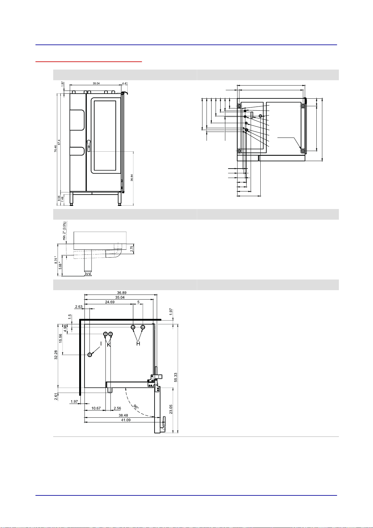
32.28
35.04
1.02
32.99
3.9
23.23
7.02
9.08
6.43
15.28
16.27
2.95
1.97
3.27
7.1
12
5.16
4.06
4.84
2.87
4.65
12.72
[
A
B
M
C
F
G
D
E
J
10 Connection drawings
C4 20.10 dimensions and connection points (disappearing door)
Front view Connection points, unit floor
Drain connection detail
* The distance depends on how much
the feet are extended (max. +0.984")
View from above with wall clearances Key
A Water connections (for boiler or water injec‐
B Water connections (for cleaning, recoil
C Drain connection (2" internal diameter)
D Electrical connection
E Bonding
F Rinse-aid connection (optional)
G Cleaning-agent connection (optional)
H Air vent (2" internal diameter)
I Dry air intake (2" internal diameter)
J Gas connection
K Exhaust outlet (2" internal diameter)
M Safety overflow 3.2" x 1"
tion)
hand shower)
Installation Manual 99
Page 100
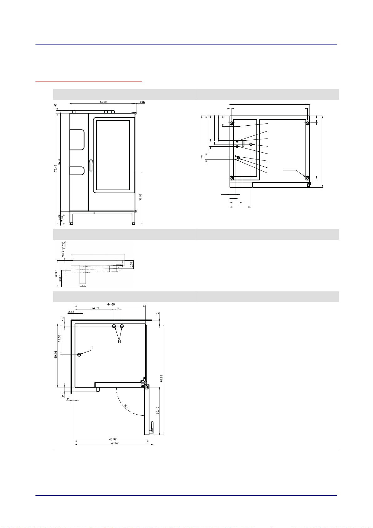
1.02 42.6
31.1
44.7
3.3
4.1
6.9
11.8
3
13.9
16
3.
9
40.2
14.3
22.6
23.7
2
6
1.97x1.97
M
C
A
B
D
F
G
E
10 Connection drawings
10.7 Convotherm 4 20.20 Electrical units
C4 20.20 dimensions and connection points (right-hinged unit door)
Front view Connection points, unit floor
Drain connection detail
* The distance depends on how much
the feet are extended (max. +0.984")
View from above with wall clearances Key
A Water connections (for boiler or water injec‐
B Water connections (for cleaning, recoil
C Drain connection (2" internal diameter)
D Electrical connection
E Bonding
F Rinse-aid connection (optional)
G Cleaning-agent connection (optional)
H Air vent (2" internal diameter)
I Dry air intake (2" internal diameter)
M Safety overflow 3.2" x 1"
tion)
hand shower)
Installation Manual 100
 Loading...