

Page 1
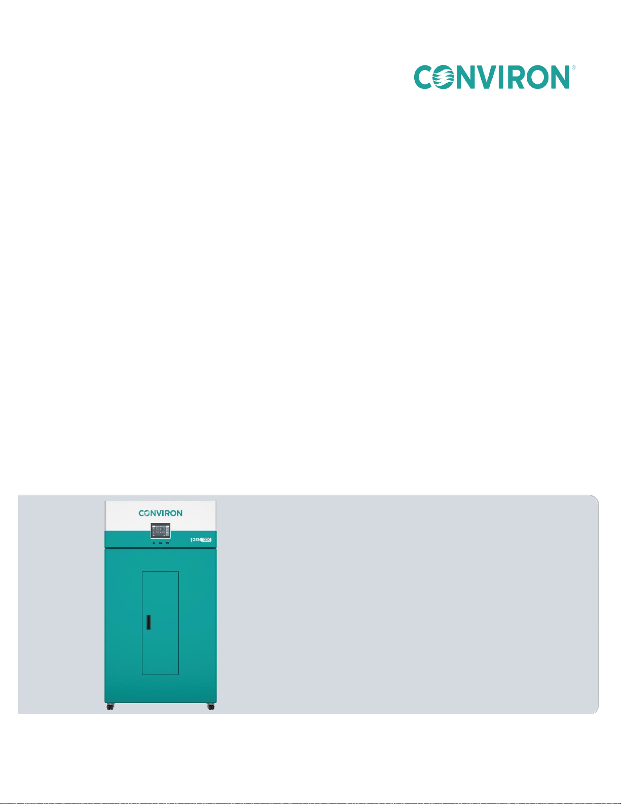
GEN1000
OPERATOR MANUAL
287960-ENG
R00
Page 2

GEN1000
OPERATOR MANUAL
Please read these instructions carefully
and completely before operating the
chamber.
Conviron Document Number 287960-ENG R00
Published by:
CONVIRON 590 Berry Street
Winnipeg, Manitoba
Canada, R3H 0R9
www.conviron.com
July 22, 2019
Printed in Canada
2019 Controlled Environments Limited
Conviron is a registered trademark of Controlled Environments Limited. All other trademarks are the property of their
respective owners. Information subject to change without written notice.
Page 3

PREFACE
Welcome to the GEN1000 Operator Manual.
This manual describes the features and use of Conviron’s GEN1000 chamber and is designed
to provide sufficient detail for the different kit configurations, including a structured format
providing step-by-step instructions. Clients will find sufficient detail for a typical installation
including figures, diagrams, and graphics to operate the chamber without issue. However, given
that many installations are specific to each facility and that facilities may have unique
requirements, additional information or assistance from Conviron may be required.
This equipment is only to be used by authorized personnel - that is, personnel who have been
trained in the proper use of the equipment and who have read this manual.
Latest Manual Versions and Languages
For the latest version of this and other manuals, please visit www.conviron.com.
For manuals in other languages, or for additional printed manuals, please contact Conviron
head office.
Functional Description/Intended Use
This chamber is designed to provide a controlled environment for plant production and scientific
experiments including, but not limited to, plant science, biotechnology, and entomology.
July 22, 2019 | 287960-ENG | R00 i
Page 4
Products labeled with the WEEE symbol (a crossed out ″waste
bin″) indicate that the final user should not discard this product
along with other household waste, but that it must be collected
and treated separately.
The “PLEASE NOTE” symbol is used to draw attention to additional information which
WEEE and RoHS Compliance Statements
CONVIRON is committed to meeting all requirements of the WEEE directive (2012/19/EU).
Please contact Conviron, or your Conviron distributor, for proper handling and disposal
instructions.
Conviron is committed to meeting all requirements of the RoHS directive (2011/65/EU). The
RoHS directive requires that manufacturers eliminate or minimize the use of lead, mercury,
hexavalent chromium, cadmium, polybromated biphenyls, and polybromated biphenyl ethers in
electrical and electronic equipment sold in the EU after July 1, 2006.
Document Conventions
Conviron maintains a policy of continual improvement and reserves the right to change the
product without prior notice. Therefore, the images used throughout this manual may differ
slightly from the actual configuration due to updates and product changes.
Wherever possible, textual descriptions are accompanied by photographs or line
drawings of the chambers to assist the reader in understanding the material.
Frequent reference is made to left and right sides throughout this manual. Left is
considered to be the left-hand side while facing the equipment.
Indented bold and italicized text is used to introduce instructions.
Italicized text is used to identify additional reference manuals.
Red circles or colored highlights are used to highlight important assembly or
disassembly details, or to show important small parts in an otherwise large assembly.
may assist in the operation of the equipment.
ii July 22, 2019 | 287960-ENG | R00
Page 5

SERVICE & TECHNICAL SUPPORT
Before contacting Conviron, please check the following:
Read this document and the accompanying controller manual in their entirety before
attempting to operate the chamber.
If you are having a problem using your cabinet(s), pay particular attention to the
relevant section and the pertinent information in this manual, and use the information
to diagnose and correct the problem.
If the problem persists and/or you require additional assistance, please collect the
following information prior to contacting Conviron:
The serial number of the cabinet, located on the rating plate on the left side of
the chamber.
The software version of the control system. Instructions for obtaining the
software version of your control system are provided in the control system
operator manual.
A description of the problem.
A description of what you were doing before the problem occurred.
Head Office
Technical Services
Conviron
590 Berry St.
Winnipeg, Manitoba,
Canada R3H 0R9
Conviron Technical Services
Please visit www.conviron.com for global service contact information.
July 22, 2019 | 287960-ENG | R00 iii
Page 6

TABLE OF CONTENTS
1 PRECAUTIONS...................................................................................................................................... 1
1.1 Hazard Identification Symbols ....................................................................................................... 1
1.2 General Precautions ...................................................................................................................... 2
2 CHAMBER FEATURES ......................................................................................................................... 5
2.1 Configurations ............................................................................................................................... 5
2.2 Control System .............................................................................................................................. 5
2.3 Air Intake and Exhaust .................................................................................................................. 5
2.4 Instrumentation Ports .................................................................................................................... 5
2.5 Network Connectivity ..................................................................................................................... 5
2.6 Levelers ......................................................................................................................................... 6
2.7 Central Management System (Optional) ....................................................................................... 6
2.8 CMP-Link (Optional) ...................................................................................................................... 6
2.9 Central Alarm Contact ................................................................................................................... 6
2.10 Options .......................................................................................................................................... 7
3 INSTALLATION ..................................................................................................................................... 9
3.1 Install the Chamber ....................................................................................................................... 9
3.1.1 Chamber Clearance ....................................................................................................... 9
3.1.2 Power Supply ................................................................................................................. 9
3.1.3 Water Supply ............................................................................................................... 10
3.1.4 Condensate Drain ........................................................................................................ 10
3.2 Remove the Chamber from the Shipping Pallet .......................................................................... 10
3.3 Move the Chamber Into Final Position ........................................................................................ 12
3.4 Level the Chamber ...................................................................................................................... 12
3.5 Configuration Kit Overview .......................................................................................................... 13
3.5.1 Airflow .......................................................................................................................... 13
3.5.2 Adjustable Wire Shelves and Lamp Canopies ............................................................ 14
3.5.3 Unifloor® (TA Kit) ......................................................................................................... 15
3.6 Install the Light Canopies and Shelving Configuration Kits......................................................... 15
3.6.1 SH Configuration.......................................................................................................... 16
3.6.2 TA Configuration .......................................................................................................... 21
3.6.3 TC Configuration .......................................................................................................... 24
3.6.4 IN Configuration ........................................................................................................... 28
3.7 Remove the Light Canopies and Shelves ................................................................................... 32
iv July 22, 2019 | 287960-ENG | R00
Page 7

3.7.1 Remove a Wire Shelf ................................................................................................... 32
3.7.2 Remove a Wire Shelf Clip ............................................................................................ 32
3.7.3 Remove an Air Shelf .................................................................................................... 32
3.7.4 Remove an Air Shelf Bracket ....................................................................................... 33
3.7.5 Remove the Unifloor .................................................................................................... 33
3.7.6 Remove a Cover Plate ................................................................................................. 33
3.8 Connect the UPS, Communication, and Central Alarm Contacts ............................................... 33
3.9 Connect the Electrical Cord ......................................................................................................... 34
4 START UP ............................................................................................................................................ 35
4.1 Power ON .................................................................................................................................... 35
4.1.1 Start-Up Procedure ...................................................................................................... 35
4.2 Visual Checks .............................................................................................................................. 36
5 OPERATION ........................................................................................................................................ 37
5.1 Control and Monitoring ................................................................................................................ 37
5.2 Fluorescent and LED Lighting ..................................................................................................... 37
5.3 Lighting Options ........................................................................................................................... 38
5.3.1 Fluorescent Lighting .................................................................................................... 38
5.3.2 LED Lighting – LED Option .......................................................................................... 38
5.3.3 Closed Loop Dimmable Lighting System ..................................................................... 38
5.4 Aspirator ...................................................................................................................................... 39
5.5 Instrumentation Port .................................................................................................................... 39
5.6 Fresh Air Inlet and Exhaust Ports ................................................................................................ 40
5.7 Fan Speed Control ...................................................................................................................... 41
5.8 Plant Placement .......................................................................................................................... 41
5.9 Bypass Dehumidification – BDH Option ...................................................................................... 41
5.10 Additive Carbon Dioxide Control – CO2 Option ........................................................................... 42
5.10.1 Set up the Additive CO2 Control .................................................................................. 42
5.10.2 Adjust the CO2 Control ................................................................................................. 42
5.11 Central Management System – CMS Option .............................................................................. 43
5.12 Shutdown ..................................................................................................................................... 43
6 MAINTENANCE ................................................................................................................................... 45
6.1 Disconnect the Power Before Maintaining or Servicing the Chamber ........................................ 46
6.2 Clean the Chamber ..................................................................................................................... 46
6.3 Replace Fluorescent or LED Lamps ........................................................................................... 46
6.4 Perform Maintenance in the Machine Compartment ................................................................... 48
July 22, 2019 | 287960-ENG | R00 v
Page 8

6.5 Maintain the Ultrasonic Humidity System (USH) ......................................................................... 49
6.6 Calibrate the Temperature and Humidity Sensor ........................................................................ 51
6.7 Adjust the Door ............................................................................................................................ 51
6.8 Clean the Condensate Pump and Condensate Pan ................................................................... 51
7 TROUBLESHOOTING ......................................................................................................................... 53
7.1 Troubleshooting Steps................................................................................................................. 53
7.2 Fuse Schedule ............................................................................................................................. 54
8 TECHNICAL SPECIFICATIONS .......................................................................................................... 55
9 ADDITIONAL INFORMATION ............................................................................................................. 57
9.1 Terms & Definitions ..................................................................................................................... 57
9.2 Disposal ....................................................................................................................................... 58
vi July 22, 2019 | 287960-ENG | R00
Page 9

LIST OF FIGURES
Figure 3-1 Remove the L-Brackets .................................................................................................... 10
Figure 3-2 Position the Forks ............................................................................................................. 10
Figure 3-3 Remove the Chamber from the Pallet Using the Optional Ramp ..................................... 11
Figure 3-4 Chamber Levelers ............................................................................................................. 12
Figure 3-5 Chamber Airflow ................................................................................................................ 13
Figure 3-6 Wire Shelf Supports .......................................................................................................... 14
Figure 3-7 Canopy Supports and Connections .................................................................................. 14
Figure 3-8 Unifloor .............................................................................................................................. 15
Figure 3-9 SH Configuration ............................................................................................................... 16
Figure 3-10 SH X-TIER Configuration .................................................................................................. 16
Figure 3-11 Open Plenum .................................................................................................................... 17
Figure 3-12 Perforated Cover Plates .................................................................................................... 17
Figure 3-13 Cover Plate Screw Detail .................................................................................................. 18
Figure 3-14 Install the Shelf Clips......................................................................................................... 18
Figure 3-15 Shelf Installed onto Clips .................................................................................................. 19
Figure 3-16 Install the Canopy Support Brackets ................................................................................. 19
Figure 3-17 Install the Canopies........................................................................................................... 20
Figure 3-18 SH Canopies ..................................................................................................................... 20
Figure 3-19 SH X-Tier .......................................................................................................................... 20
Figure 3-20 Control Connection ........................................................................................................... 20
Figure 3-21 Power Connection ............................................................................................................. 20
Figure 3-22 TA Configuration ............................................................................................................... 21
Figure 3-23 Solid Cover Plates............................................................................................................. 22
Figure 3-24 Install the Canopy Support Brackets ................................................................................. 22
Figure 3-25 Install the Canopies........................................................................................................... 23
Figure 3-26 TA Canopy Connection ..................................................................................................... 23
Figure 3-27 Control Connection ........................................................................................................... 23
Figure 3-28 Power Connection ............................................................................................................. 23
Figure 3-29 TC Configuration ............................................................................................................... 24
Figure 3-30 Slotted Cover Plates ......................................................................................................... 25
Figure 3-31 Air Shelf Bracket ............................................................................................................... 25
Figure 3-32 Shelf Installed onto Clips .................................................................................................. 26
Figure 3-33 Install the Canopy Support Brackets ................................................................................. 26
Figure 3-34 Install the Canopies........................................................................................................... 27
Figure 3-35 TC Canopy Connection ..................................................................................................... 27
Figure 3-36 Control Connection ........................................................................................................... 27
Figure 3-37 Power Connection ............................................................................................................. 27
Figure 3-38 IN Configuration ................................................................................................................ 28
Figure 3-39 Open Plenum .................................................................................................................... 29
Figure 3-40 Perforated Cover Plates .................................................................................................... 29
Figure 3-41 Cover Plate Screw Detail .................................................................................................. 29
Figure 3-42 Install the Shelf Clips......................................................................................................... 30
Figure 3-43 Shelf Installed onto Clips .................................................................................................. 30
Figure 3-44 Install the Canopy Support Brackets ................................................................................. 31
July 22, 2019 | 287960-ENG | R00 vii
Page 10

Figure 3-45 Install the Canopies........................................................................................................... 31
Figure 3-46 IN Canopy Connection ...................................................................................................... 31
Figure 3-47 Control Connection ........................................................................................................... 32
Figure 3-48 Power Connection ............................................................................................................. 32
Figure 3-49 Back Panel Connections ................................................................................................... 33
Figure 5-1 Aspirator ............................................................................................................................ 39
Figure 5-2 Instrumentation Port Location ........................................................................................... 40
Figure 5-3 Fresh Air Inlet and Exhaust Port Location ........................................................................ 41
Figure 6-1 LED Tube Orientation ....................................................................................................... 47
Figure 6-2 Remove the Screws from the Top Cover .......................................................................... 48
Figure 6-3 Remove the USH Box from the Chamber ......................................................................... 49
Figure 6-4 Remove the USH Box Lid ................................................................................................. 50
Figure 6-5 Ceramic Disc Replacement .............................................................................................. 50
Figure 8-1 Sample GEN1000 Rating Plate ........................................................................................ 56
LIST OF TABLES
Table 1-1 Hazard Identification Symbols ............................................................................................ 1
Table 3-1 Water Supply Parameters ................................................................................................. 10
Table 3-2 Back Panel Connection Descriptions ................................................................................ 34
Table 9-1 Terms and Definitions ....................................................................................................... 57
viii July 22, 2019 | 287960-ENG | R00
Page 11
1 PRECAUTIONS
Symbol
Description
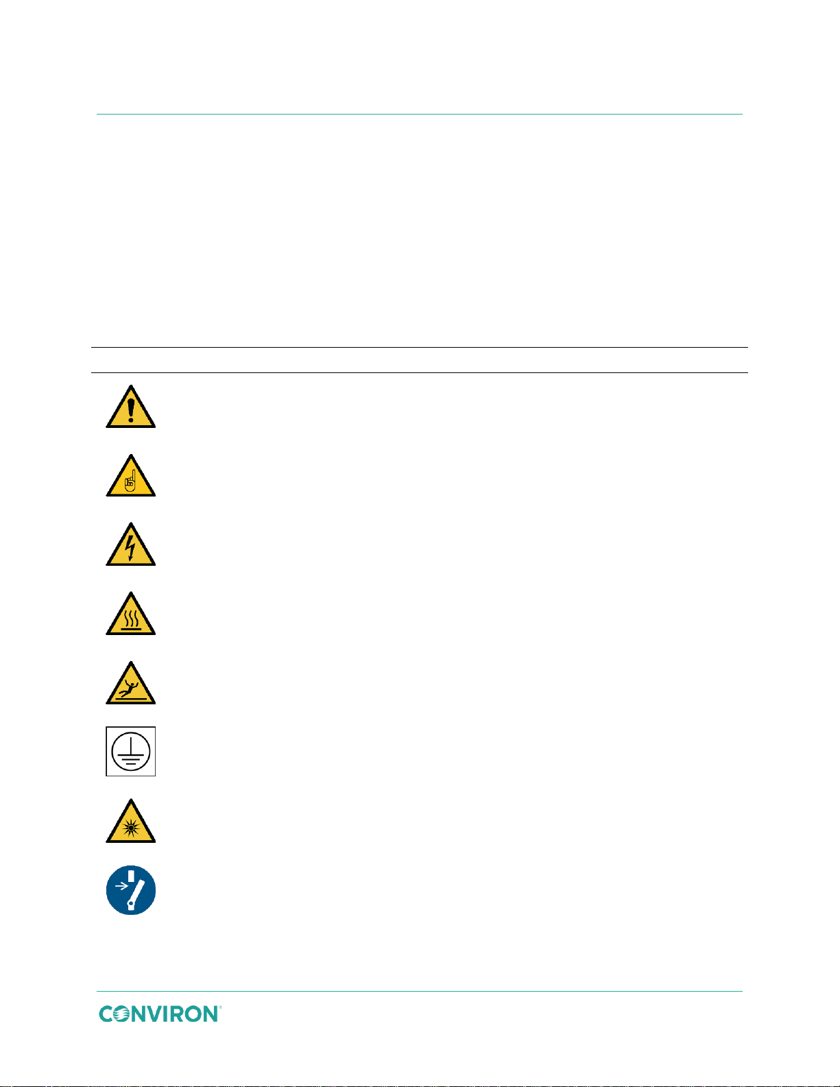
The ″HAZARD WARNING″ symbol is used whenever a general hazard exists which
could cause personal injury or potential equipment damage, and requires correct
procedures/practices for prevention.
The ″IMPORTANT INFORMATION″ symbol is used to identify operating procedures
which must be followed to ensure smooth and efficient equipment operation.
The ″ELECTRICAL SHOCK/ELECTROCUTION″ symbol is used to identify a
source of potentially dangerous electrical current.
The ″BURN HAZARD/HOT SURFACE″ symbol is used to identify surfaces which
are hot enough to cause personal injury.
The ″SLIP HAZARD″ symbol is used to identify a potential hazard of falling from
elevated surfaces.
The ″PROTECTIVE EARTH-GROUND″ symbol is used to identify the protective
earth connection.
The ″OPTICAL RADIATION″ symbol is used to identify areas where exposure to
ultraviolet (UV) and infrared radiation may be possible.
The ″DISCONNECT MAINS POWER″ symbol is used remind service personnel to
disconnect the power at the mains panel before servicing this equipment.
The equipment is intended to be installed, operated, maintained, and serviced by only trained
personnel, according to the instructions and precautions described in the manuals provided by
Conviron.
Table 1-1 lists precautions intended to help guide users in the safe operation of Conviron
chambers.
1.1 Hazard Identification Symbols
Table 1-1 Hazard Identification Symbols
July 22, 2019 | 287960-ENG | R00 1
Page 12
Symbol
Description
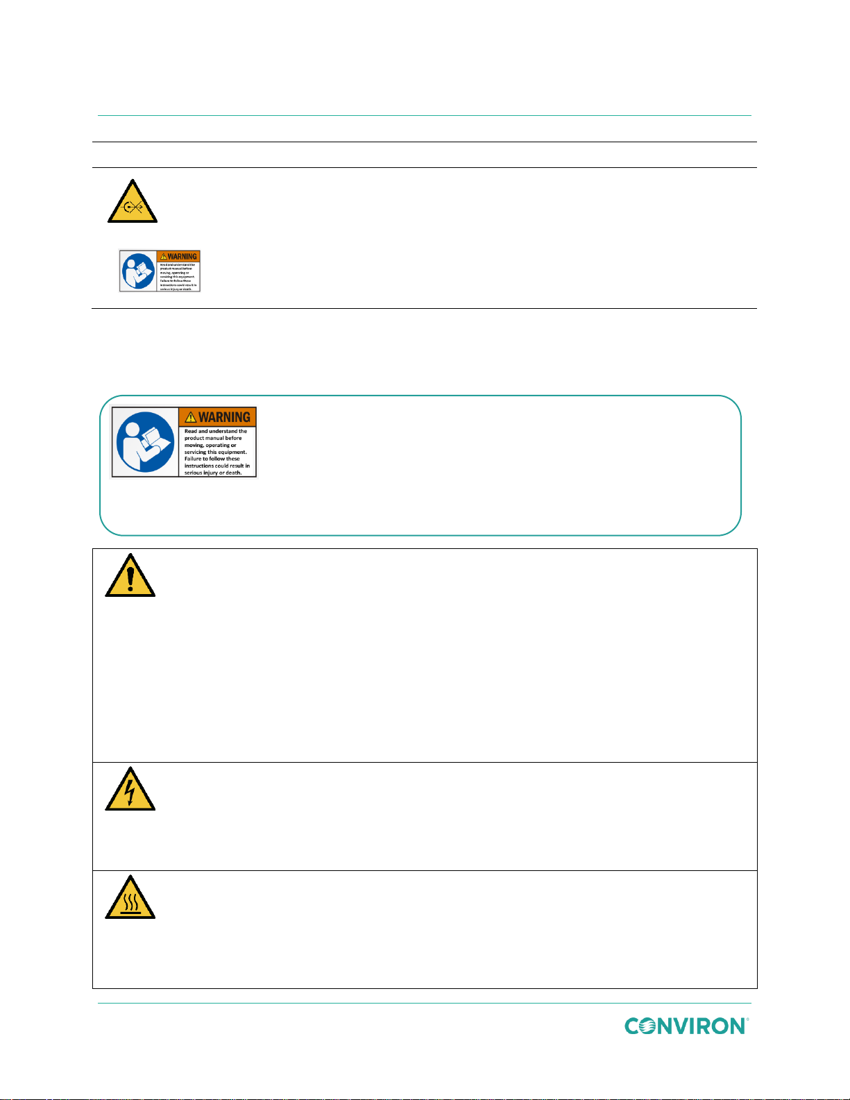
The ″DO NOT DISCONNECT UNDER LOAD″ symbol is used to remind the user to
shut off the power to the receptacle before removing the plug.
The ″READ THE OPERATOR MANUAL″ label is intended to remind the
user to have a thorough understanding of the equipment BEFORE use.
Conduct a visual inspection of the equipment and surrounding area by walking
around the unit to ensure no debris or obstacles are present that could pose a safety
hazard before operating the chamber.
Operate your Conviron equipment for a minimum of five days before introducing any
research material to ensure proper and stable operation.
Avoid direct contact with any broken fluorescent lamps. Fluorescent lamps are
extremely fragile and may emit harmful vapors when broken.
Follow all applicable local environmental regulations and guidelines for disposal of
hazardous material. If in doubt, contact local authorities for proper disposal
procedures.
Warning: Electricity hazard
Serious personal injury or death could result from contact with live electrical circuits.
Tool accessible areas are for qualified service people only.
Disconnect power before accessing.
Warning: Hot surface hazards
Personal injury could result from contacting hot surfaces within the chamber.
The user accessible fluorescent lamps, the inaccessible refrigeration system
components, and the inaccessible heater element become hot during normal
operation. Do not touch.
Warning: Read and understand the product manuals before
and followed before working with the product.
GEN1000 Operator Manual
1.2 General Precautions
These precautions should be read and understood before proceeding with installation,
operation, and maintenance.
moving, installing, operating, or servicing this equipment.
Failure to follow these instructions could result in equipment
damage, serious personal injury, or death.
The manual contains safety information that must be understood
2 July 22, 2019 | 287960-ENG | R00
Page 13
Precautions
Warning: Slip and fall hazard
Personal injury could result.
Clean up any spilled or accumulated water immediately. Contact maintenance
personnel if the problem recurs.
Warning: Optical radiation hazard
Personal injury could result from unprotected exposure. The lighting system in this
product produces potentially dangerous ultraviolet and infrared radiation in close
proximity.
Always wear protective clothing such as gloves and long sleeve shirts when working
within the chamber.
Always wear protective glasses when working within the chamber that are CSA
Z94.3-07 or ANSI Z87.1-2010 compliant and block 99.9% of UVA/UVB/UVC rays. Do
not look directly at the lights even while wearing protective glasses.
Warning: Electrical Shock Hazard
Serious personal injury or equipment damage could result from contacting live
electrical circuits.
An arc flash risk assessment should be performed to determine the voltage, shock
boundaries and PPE requirements to protect workers from electrical hazards.
Water splash hazard
Splashed water in contact with live electrical components could result in serious
personal injury or serious equipment damage.
Do not allow water or liquids to contact any electrical components.
If water comes into contact with electrical components, disconnect power
immediately at the mains and have the chamber inspected by service personnel
before putting the chamber back into use.
July 22, 2019 | 287960-ENG | R00 3
Page 14

GEN1000 Operator Manual
4 July 22, 2019 | 287960-ENG | R00
Page 15

2 CHAMBER FEATURES
2.1 Configurations
The base GEN1000 chamber can be fitted with any of the following specially configured kits and
each kit is also available with an LED lighting option:
An SH kit is either a two-tier or an SH-XTIER three-tier configuration using horizontal
airflow over multiple shelves optimizing the growth area for shorter plants, like
Arabidopsis. Ideal for research in propagation, genetics, physiology, and other moderate
light experiments.
The TA kit is a single-tier configuration providing upward airflow, maximum growth height
and light intensity for taller plants such as cereal crops, horticultural plants, and
silviculture.
The TC kit is a four-tier configuration using low light to maximize space. It also provides
upward airflow minimizing condensation in petri dishes and jars used in propagation and
genetics experiments.
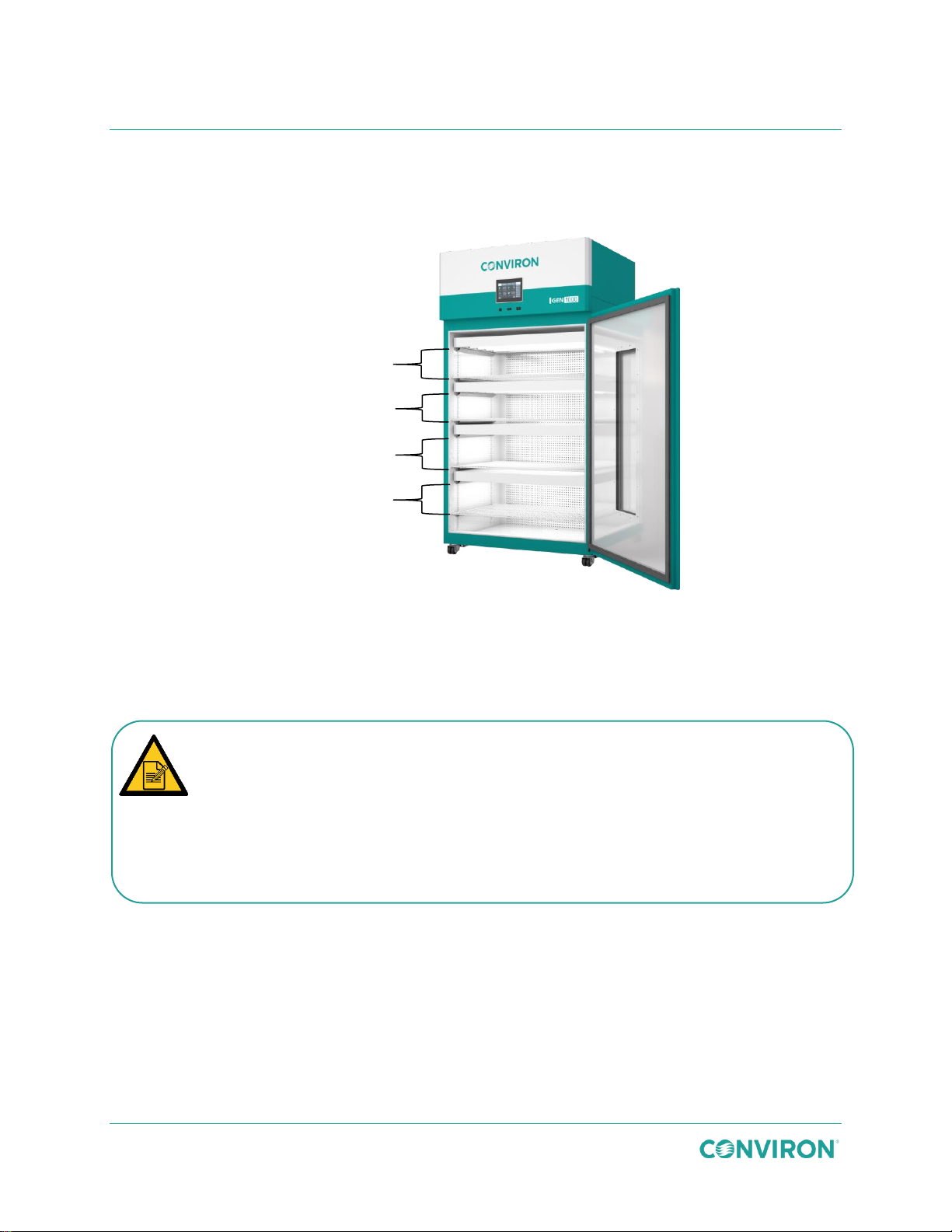
The IN kit is a four-tier configuration using horizontal airflow and low light levels
optimizing the incubation of plantlets and insects.
2.2 Control System
The control system provides advanced programming capabilities, allowing ramping or stepping
of environmental conditions to match research requirements. User programmable ″set and
forget″ alarms track the chamber operation relative to user-defined setpoints. Visual and audible
notifications provide a further level of protection. For remote monitoring and control, the
chamber comes ready to communicate with Conviron’s Central Management™ or CMP-Link.
Refer to the included Conviron CMP6060 Operator’s Manual for complete instructions.
2.3 Air Intake and Exhaust
The chamber includes manually adjustable fresh air intake and exhaust ports to allow for
chamber air exchanges. Exhaust air flows to ambient with no additional connection required.
2.4 Instrumentation Ports
One 2″ (50mm) access port with a light-tight cap is provided on the right side of the chamber.
The port allows small instruments and monitor leads to be inserted into the chamber without
opening the front door, and without significantly changing the environment within the chamber.
2.5 Network Connectivity
An RJ45 port is included for connection to the facility network.
July 22, 2019 | 287960-ENG | R00 5
Page 16

GEN1000 Operator Manual
2.6 Levelers
The unit is supplied with levelers to stabilize the chamber in it’s final location and compensate
for variations in the finished floor.
2.7 Central Management System (Optional)
For use in conjunction with the 6000 series controllers, the Conviron Central Management™
(CM) system provides a comprehensive suite of time-saving, value-added features for remote
control and monitoring of chambers, such as:
A supervisory dashboard that provides a quick overview of all operational chambers.
Thumbnail properties that show essential chamber management details.
Triggers that protect the experiment by alerting designated personnel.
Risk management that includes auto backup and restore, system protection, disaster
recovery, and file restoration.
Data management capabilities that include collection and storage.
Refer to the Conviron Central Management Operator`s Manual for complete instructions.
2.8 CMP-Link (Optional)
The CMP-LINK feature enables Argus Titan 900 full interaction of any Conviron chamber or
room that is equipped with CMP6060 control system. With CMP-LINK enabled, features of Titan
900 such as scheduling and programming, table views for data, comprehensive graphing, realtime status (including alarms, sensors and IOs), retrieval and exporting of chamber data, time
synchronization and a remote interface are available for the chamber.
2.9 Central Alarm Contact
The Central Alarm Contact (CAC) (Figure 3-49) consists of a normally closed dry contact
energized by a control system alarm output that is connected to a Building Management System
(BMS) or an optional auto dialer. When an alarm condition occurs, that contact opens,
interrupting the circuit from the BMS (or other system) to indicate an alarm. The CAC is only
triggered by shut-down alarms.
The connection point to the BMS is a receptacle on the back panel of the chamber. This
receptacle is connected to a relay that operates when a chamber alarms. The wire connections
of the receptacle must be completed according to the electrical drawings. The electrical load
must be within the rating of the technical specifications. The receptacle is mated with the plug
and then screwed tightly together.
6 July 22, 2019 | 287960-ENG | R00
Page 17
Chamber Features
No humidity control below 4°C. XTIER units with LED will achieve 5°C
2.10 Options
The GEN1000 can be ordered with the following options:
Additive Humidity – adds moisture to the chamber above the ambient level.
CO2 Additive – increases the chamber CO2 level above ambient.
CO2 Monitoring – indicates the CO2 level without controls or limits.
Condensate Pan – collects chamber condensate when direct plumbing to the floor
drain is not available or desirable.
Condensate Pan and Pump - collects chamber condensate and pumps the
condensate from the condensate pan to the floor drain when direct plumbing is not
available or desirable.
Dehumidification – removes excess humidity from the chamber.
Lighting Options
SH – Fluorescent lighting for the Short Plant configuration.
SH LED – LED lighting for the Short Plant configuration.
TA - Fluorescent lighting for the Tall Plant configuration.
TA LED - LED lighting for the Tall Plant configuration.
TC - Fluorescent lighting for the Tissue Culture configuration.
TC LED - LED lighting for the Tissue Culture configuration.
IN – Fluorescent lighting for the Incubation configuration.
IN LED – LED lighting for the Incubation configuration.
Light Sensor – allows for closed loop control of lighting intensity, measured in
micromoles.
Low Temperature – Low temperature operation of 2°C with the lights ON (No fresh air
below 8°C.) A defrost cycle will occur resulting in a temperature increase for
temperatures set below 10°C with the lights ON, 4°C with the lights OFF.
Temperature spikes and defrost time are dependent on the chamber operating
temperature. During this cycle, the lights will be turned off.
When using fluorescent lighting, specified light intensity will diminish when the
chamber is operating at low temperatures.
with the lights ON.
Observation Window – allows a clear view inside the chamber without opening the
door through a 38″ high by 9.5″ wide (650mm by 240mm) window in the door.
Phenolic Coated Refrigeration Coil – available as an addition to the IN kit when used
for insect research.
SH-XTIER – additional canopy and shelf for the Short Plant configuration.
July 22, 2019 | 287960-ENG | R00 7
Page 18

GEN1000 Operator Manual
Uninteruptable Power Supply (UPS) - provides surge protection and emergency
power to the controller only in the case of a facility power interruption.
Water Cooled Condensing Unit – used when a facility has a water chiller system, or
when an air cooled condenser system will add unwanted heat into the room.
8 July 22, 2019 | 287960-ENG | R00
Page 19
3 INSTALLATION
Failure to install overcurrent protection if fluctuation greater than 10% is detected can
GEN1000 units must be placed in ventilated areas. The ideal temperature around the
equipment is 70°F (21°C). Although it will perform at higher ambient temperatures, it is
recommended that the product be placed in areas that have circulating air.
3.1 Install the Chamber
Install the chamber in a dry, well-ventilated area with circulating air and maintain the operating
environment between a minimum temperature of 59°F (15°C) and a maximum temperature of
95°F (35°C).
It is important to ensure that the room in which the chamber is placed adheres to
these environmental conditions.
The GEN1000 chambers dissipate up to 2600W to ambient with the dehumidification option,
and up to 2100W without dehumidification.
Locate the chamber on a relatively level floor so that adjustments can be made with the levelers
to ensure the chamber is level.
3.1.1 Chamber Clearance
At least 1 ft. (300mm) must be left clear behind the back wall of the chamber.
At least 1 ft. (300mm) must be left clear above the chamber.
At least 4″ (102mm) must be left clear on each side of the chamber in order to provide
access to the instrumentation, fresh air, and exhaust ports.
3.1.2 Power Supply
Refer to Section 8 Technical Specifications on page 55 for details of the power configuration.
This unit will tolerate ±10% voltage fluctuation from the rated voltage on the serial plate. Use a
voltage stabilizer if the fluctuation is greater than ±10%.
result in serious damage to the compressor and electronic components, and will void
the warranty.
The overcurrent protection must be sized and installed by a qualified electrician.
July 22, 2019 | 287960-ENG | R00 9
Page 20
Parameter
Measurement
Connectivity
1/4″ Quick Connect
Flow
0.26 gallons / hour (1 Liter / hour) reverse osmosis
Pressure
Max. – 115 psi (7.9 bar), Min. – 5 psi (0.3 bar)
pH
7.0 ± 0.5
Filtration
< 0.00008 inch (2 microns)
Resistance
0.01 to 0.02 Megaohm-cm (MΩ-cm)
Conductivity
2.0 to 0.2 μS
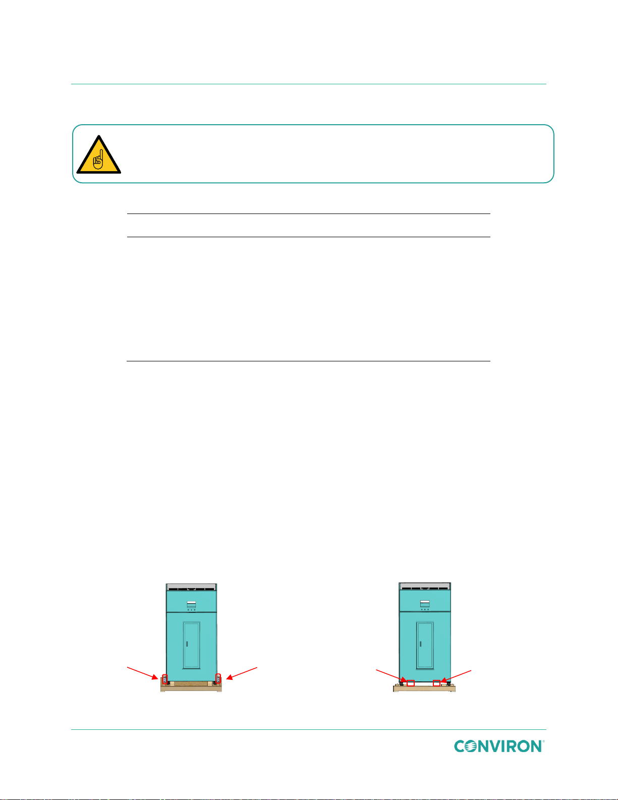
Figure 3-1 Remove the L-Brackets
Figure 3-2 Position the Forks
GEN1000 Operator Manual
3.1.3 Water Supply
Failure to use a water source with the quality stated in Table 3-1 will void the product
warranty.
Table 3-1 Water Supply Parameters
3.1.4 Condensate Drain
A 3/4″ (19 mm) drain is provided underneath the chamber, located near the back. The drain may
be extended to a nearby floor drain, as required. If there is no floor drain nearby, the optional
condensate pan may be used to collect the condensate and the optional condensate pump may
be used to pump the condensate to the drain.
3.2 Remove the Chamber from the Shipping Pallet
The GEN1000 chamber is designed to be removed from the shipping pallet with a forklift. In
smaller facilities without access to a forklift, the shipping pallet may be ordered with an optional
built-in ramp to unload the chamber.
To remove the chamber from the pallet with a fork lift:
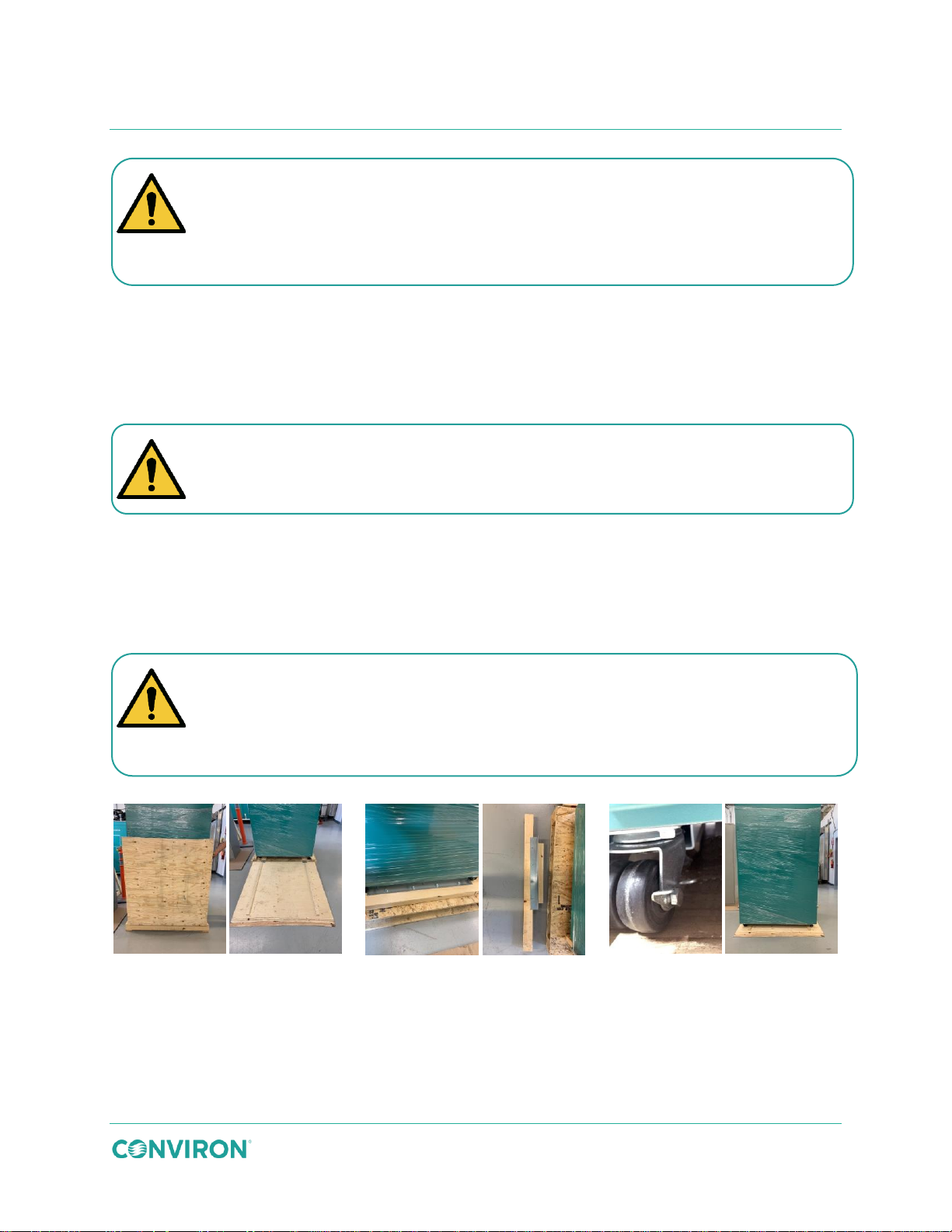
1. Remove the wooden brace and metal shipping bracket (Figure 3-1) from both sides of
the pallet.
2. Position the forks of the forklift truck as shown in Figure 3-2.
10 July 22, 2019 | 287960-ENG | R00
Page 21
Installation
Panel 1
Panel 2
Panel 3
Panel 4
Panel 5
Panel 6
Figure 3-3 Remove the Chamber from the Pallet Using the Optional Ramp
Only a trained forklift operator should attempt to remove the chamber from the pallet.
shipping pallet.
Warning: Personal injury hazard
eliminate potential puncture injuries.
Warning: Personal injury hazard
At least two people are required to control the speed of the chamber while rolling it off
the shipping pallet and down the ramp.
Warning: Severe equipment damage and potential personal injury hazard
Ensure the chamber is secured to the forklift before attempting to lift it off of the
3. Lift the chamber straight up and remove the pallet from underneath the chamber.
4. Lower the chamber to the floor.
To remove the chamber from the pallet using the optional ramp:
1. Remove the packing material and lower the ramp (Figure 3-3, Panels 1 & 2).
Do not leave any nails, staples, or screws protruding from the crating material to
2. Remove the wooden brace and metal shipping bracket (Figure 3-3, Panel 3 & 4) from
both sides of the pallet.
3. Ensure the locks on the front casters are in the unlocked position (Figure 3-3,
Panel 5).
4. Slowly roll the chamber down the ramp (Figure 3-3, Panel 6).
Do not lose control of the chamber speed while removing it from the pallet.
July 22, 2019 | 287960-ENG | R00 11
Page 22
Panel A
Panel B
Warning: Personal injury hazard
position. Ensure the chamber does not exceed a 10 degree angle while in transport.
It is important that the two front levelers are perfectly level (side to side) so the door
closes easily. An out-of-level condition on the front levelers can cause the door to bind
due to misalignment.
GEN1000 Operator Manual
3.3 Move the Chamber Into Final Position
The chamber casters make moving the chamber into final position easy and straightforward.
The chamber could cause serious personal injury if it falls while moving into final
To move the chamber into position:
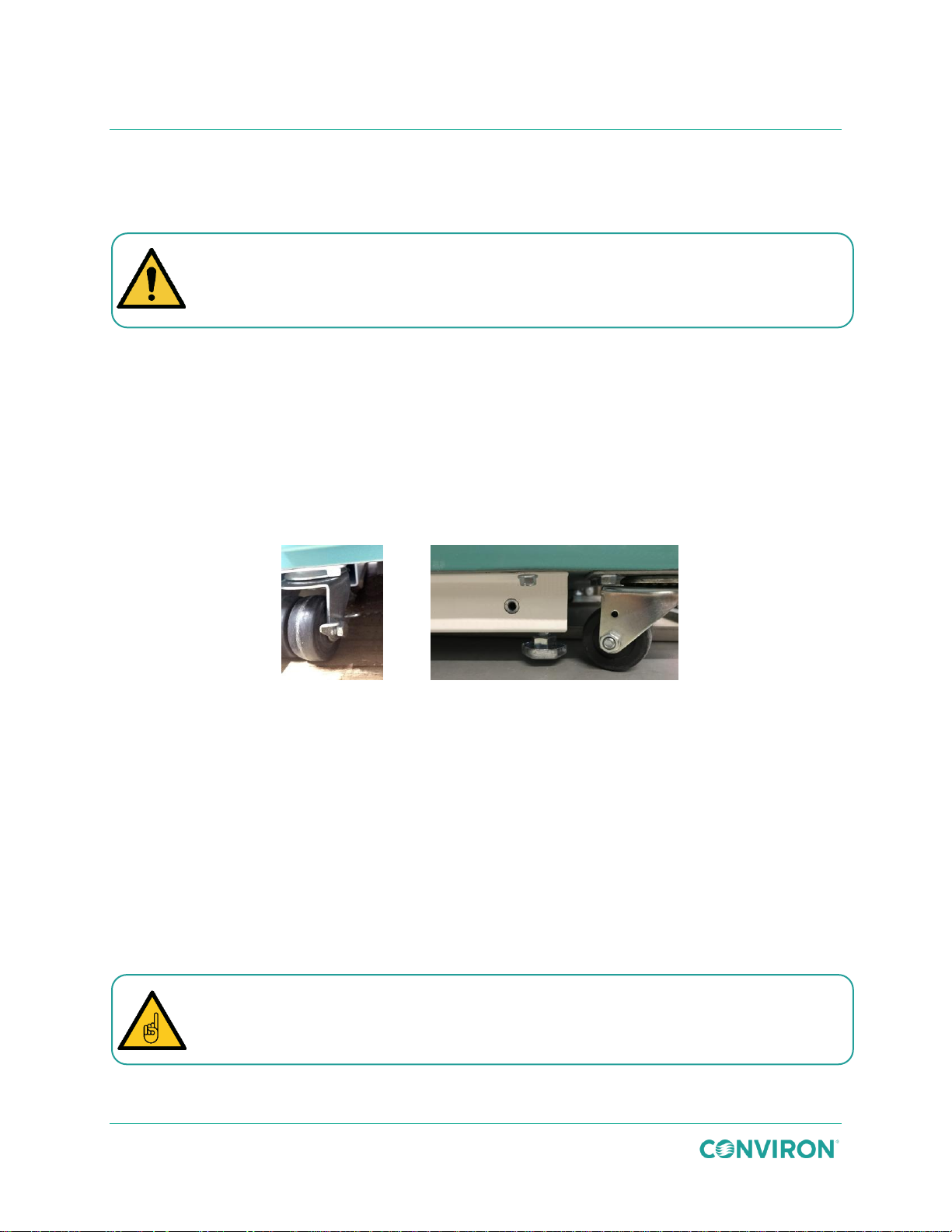
1. Ensure the locks on the front casters are in the unlocked position (Figure 3-4, Panel
A).
2. Slowly push the chamber into its final location.
3.4 Level the Chamber
The GEN1000 is equipped with four levelers (Figure 3-4, Panel B) to prevent the unit from
rolling on its casters once installed, and to compensate for any variations in the floor level.
Figure 3-4 Chamber Levelers
The levelers at the four corners at the bottom of the base must be adjusted to take the weight of
the unit off of the casters. Once the chamber is moved into position, adjust the levelers until they
are in firm contact with the floor and the chamber is level.
To adjust the levelers:
1. Use a ¾″ (18mm) open end wrench, or a medium sized adjustable wrench, to turn the
levelers under the back wall of the chamber clockwise to lower the foot into firm
contact with the floor.
2. Adjust the levelers under the front corners until the gap between the caster and the
floor is at least 1/8″ (3mm) and no more than 1/4″ (6mm).
3. Ensure the chamber is level in both the side-to-side and front-to-back directions for
proper drainage.
12 July 22, 2019 | 287960-ENG | R00
Page 23
Installation
Short Plant
Tall Plant
Tissue Culture
Incubation
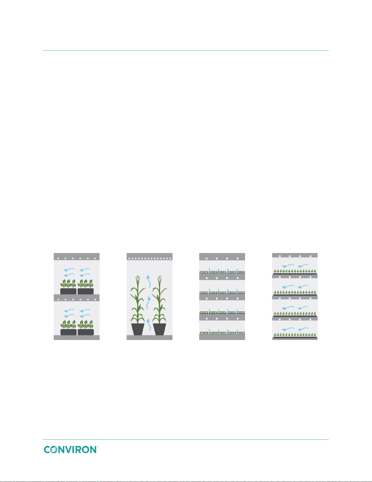
Growth Area 11.3 ft2 (1.05m2)
Spacing 20” (510mm)
Growth Area 6.3 ft2 (2.1m2)
Growth Height 43.5” (216mm)
Growth Area 22.6 ft2 (2.1m2)
Spacing 6.5” (165mm)
Growth Area 22.6 ft2 (2.1m2)
Spacing 8.5” (216mm)
Figure 3-5 Chamber Airflow
3.5 Configuration Kit Overview
The base GEN1000 chamber can be fitted with one of four specifically configured kits, each with
airflow, lighting, and shelving designed to suit specific plants and applications. Each kit allows
researchers to convert the chamber and adapt to a variety of research programs requiring
different light intensity, airflow direction, growth height, and growth space.
3.5.1 Airflow
Continuous airflow is critical to the efficient operation of the chamber. Fresh air may be
introduced using the fresh air port located on the side of the chamber.
Conditioned air is drawn down from the refrigeration coil and enters the interior of the chamber
thought a rigid metal plenum in the rear wall of the chamber.
The SH and IN kits both use a perforated cover plate that distributes airflow from the plenum
horizontally across multiple shelves.
The TA kit uses solid cover plates and distributes uniform upward airflow through the chamber
floor.
The TC kit incorporates individual air-shelves that distribute air vertically to minimize
condensation within petri dishes and containers. Figure 3-5 shows airflow, light intensity, and
growth height comparisons between the four configurations.
July 22, 2019 | 287960-ENG | R00 13
Page 24
Slotted
Pilaster
Strip
Shelf
Support
Clip (x4)
GEN1000 Operator Manual
3.5.2 Adjustable Wire Shelves and Lamp Canopies
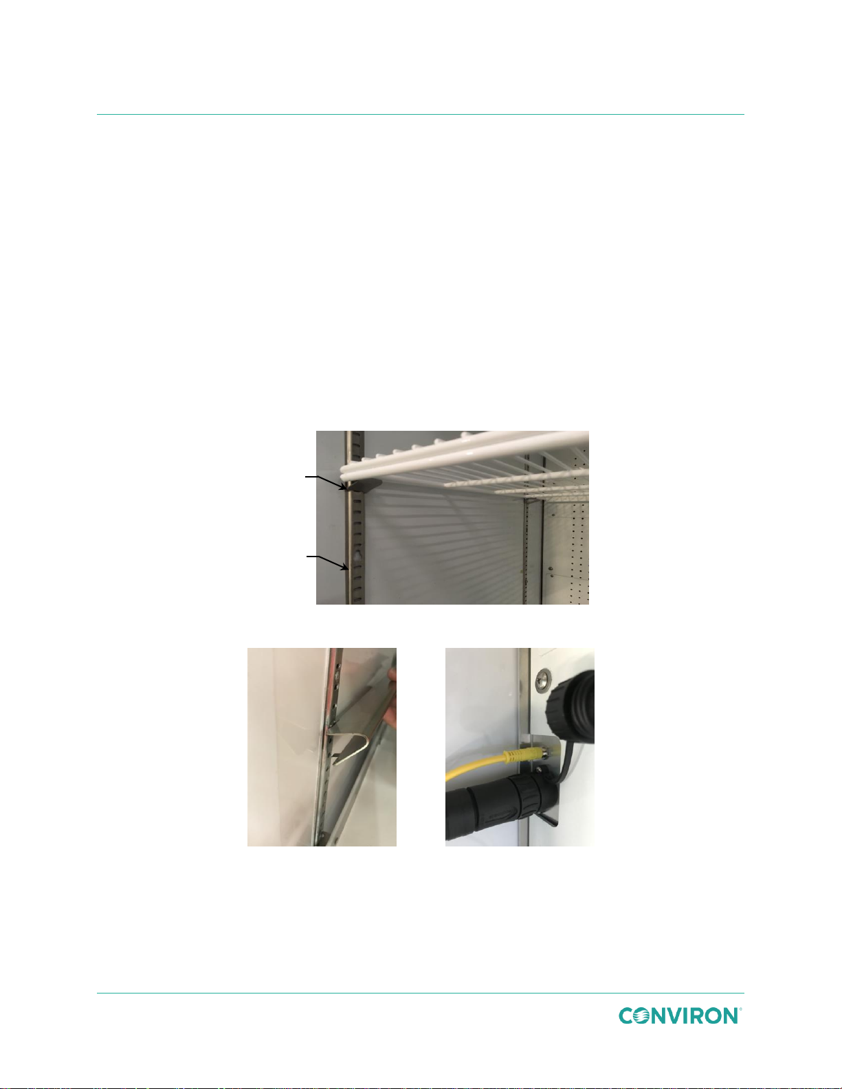
Wire shelves are supported by four metal clips attached to the four pilaster strips inside the
chamber (Figure 3-6).
Lamp canopy supports (Figure 3-7) are two long metal brackets attached between the two
pilaster strips on the same side of the chamber. The lamp canopy then simply slides onto the
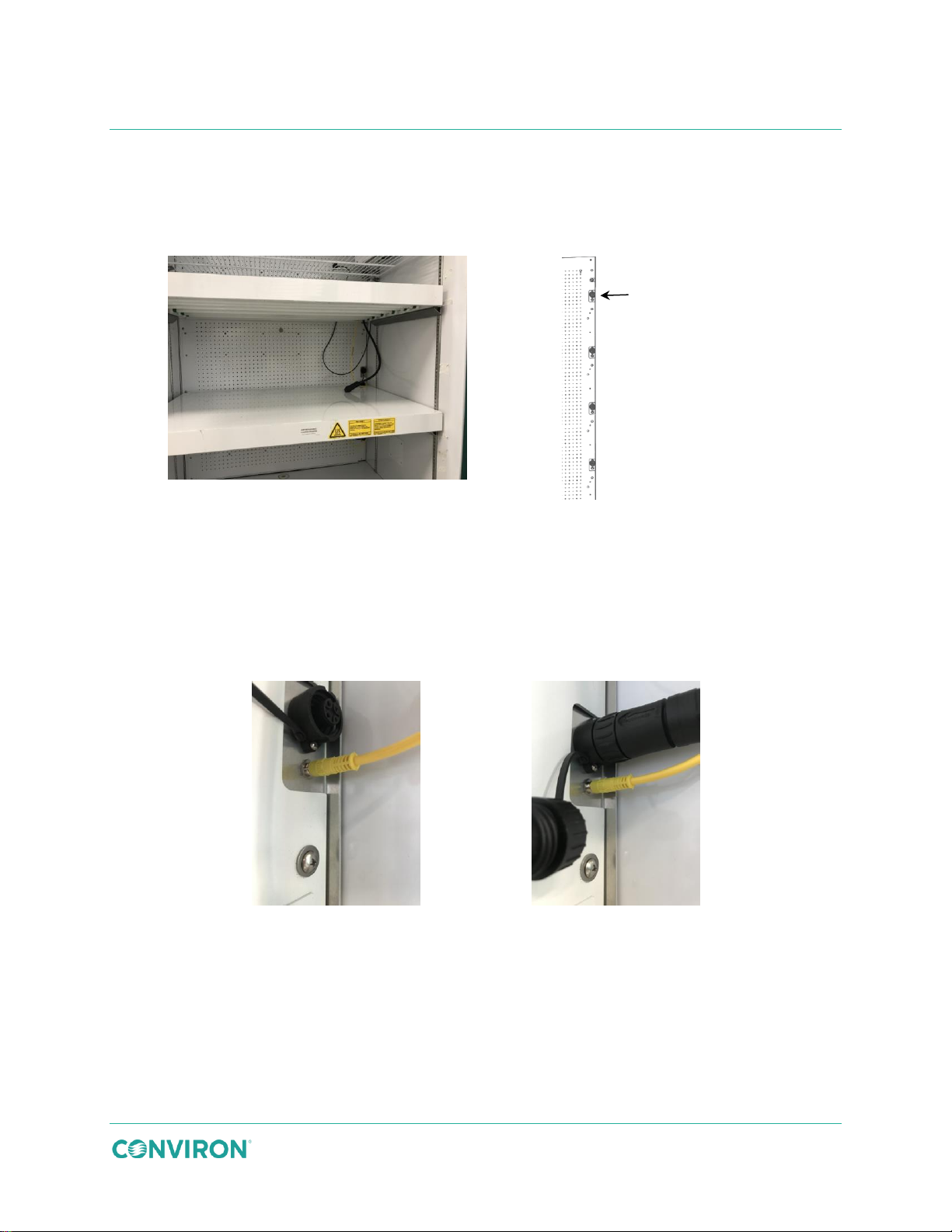
brackets and is connected to control and power receptacles on the right side of the chamber
interior. Control and power cables are color coded and equipped with unique connector plugs
(Figure 3-7).
Light Canopy Control - Four small receptacles are used to control the lighting fixtures. The
yellow plugs are mated with the receptacles and then pushed firmly together.
Light Canopy Power - Four large receptacles provide power to the lighting fixtures. The black
plugs are mated with the receptacles and then screwed tightly together.
Figure 3-6 Wire Shelf Supports
Figure 3-7 Canopy Supports and Connections
14 July 22, 2019 | 287960-ENG | R00
Page 25
Installation
3.5.3 Unifloor® (TA Kit)
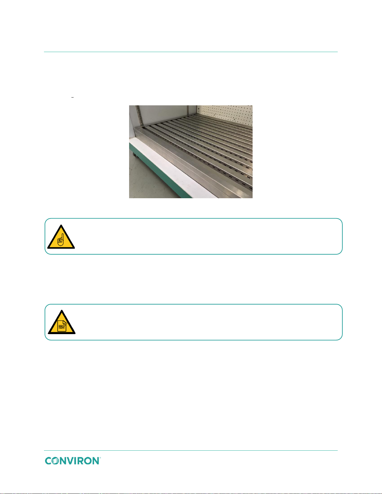
The Unifloor®, available only in the TA Kit, has openings that allow conditioned air to be
distributed evenly up through the floor into the chamber. Excess irrigation water and condensate
will drain out of the chamber to the floor drain.
Figure 3-8 Unifloor
To ensure proper airflow and water drainage, keep the vents and drain channels in
the Unifloor clear of debris.
3.6 Install the Light Canopies and Shelving Configuration Kits
Conviron chambers are configured onsite using one of four pre-packaged lighting and shelving
kits; SH for short plants, TA, for tall plants, TC for tissue culture, or IN for incubator
configuration.
Images used in the installation instruction may differ from the actual kit. However, the
installation steps and procedures are the same.
July 22, 2019 | 287960-ENG | R00 15
Page 26
20″ (51cm)
growth height
20″ (51cm)
growth height
13″ (33cm)
growth height
13″ (33cm)
growth height
12″ (31cm)
growth height
GEN1000 Operator Manual
3.6.1 SH Configuration
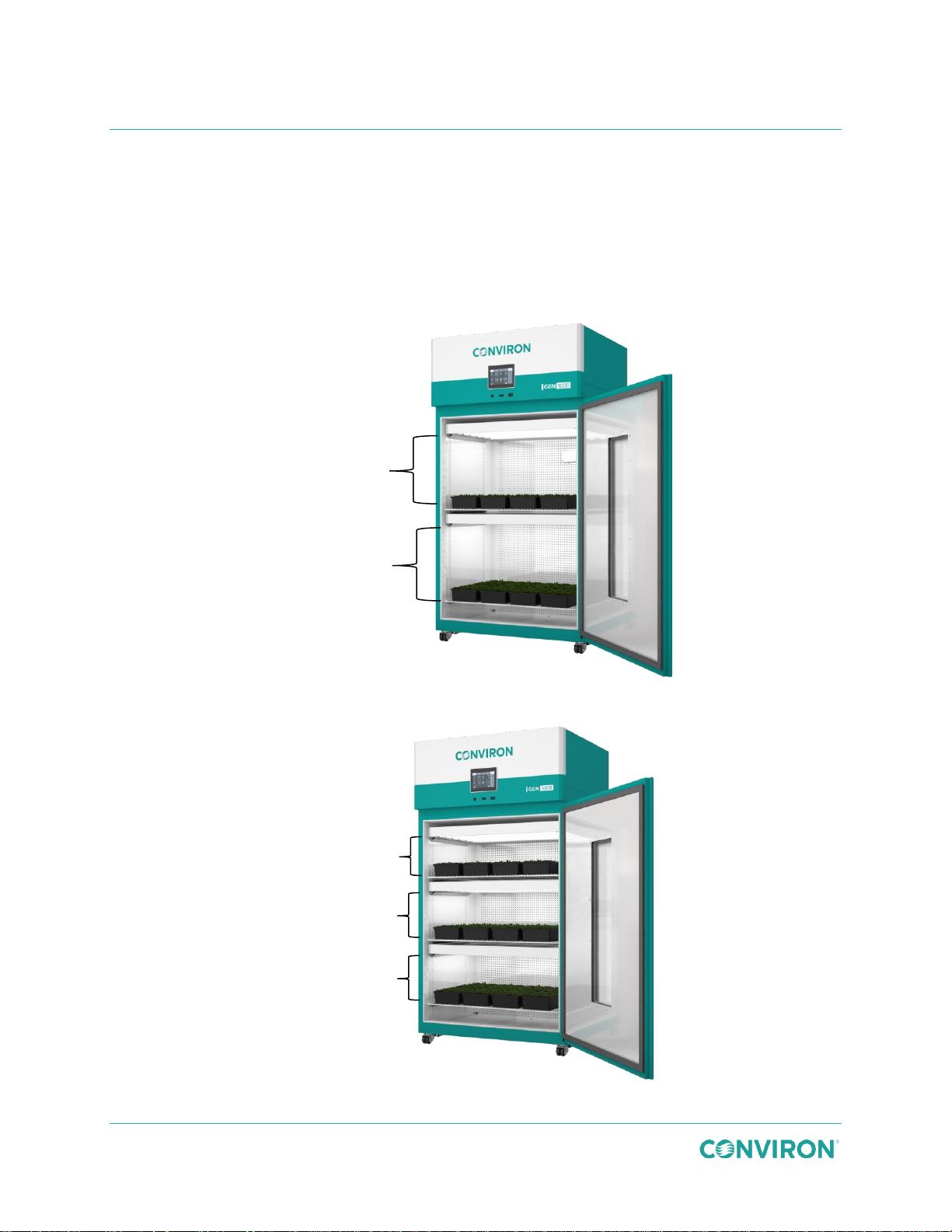
Horizontal airflow (Figure 3-5) across shelves optimizes growth area for shorter plants by forcing
the air through the perforated interior rear wall of the chamber. Cover plates are installed over
the opening in the rear wall to provide an even airflow.
The SH configuration may include an optional extra shelf and light canopy .The optional LED
lighting canopies are installed the same way as fluorescent light canopies.
Figure 3-9 SH Configuration
Figure 3-10 SH X-TIER Configuration
16 July 22, 2019 | 287960-ENG | R00
Page 27
Installation
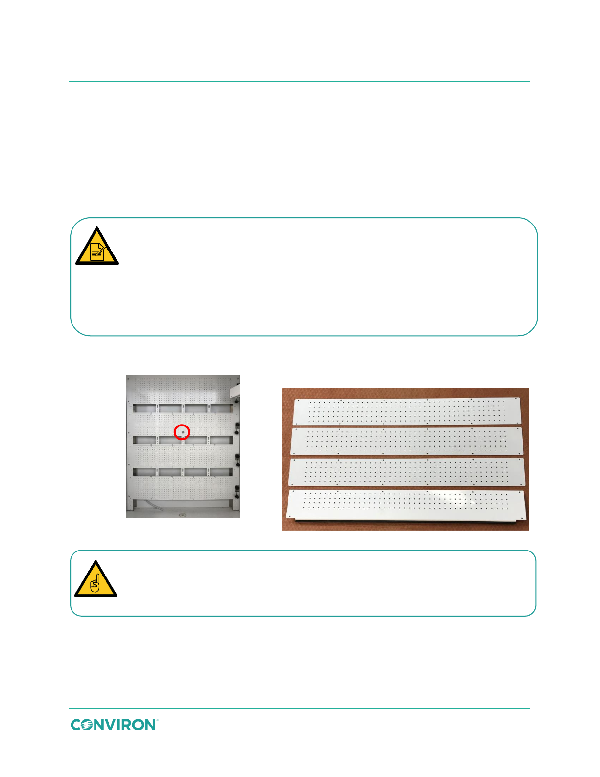
Figure 3-11 Open Plenum
Figure 3-12 Perforated Cover Plates
The chamber is shipped with the plenumn open by default. To confirm that the
) on the rear wall of the chamber is
Look through the perforated holes. If you can see through them, the plenum is open.
If not, the plenum is closed.
The cover plates are not all interchangeable. The three flat plates, shown at the top of
, must be installed over
the bottom opening.
To install the SH configuration kit:
The SH configuration may include an optional extra shelf and fluorescent light canopy
(Figure 3-10).
These basic installation instructions apply to all SH configuration shelf and lighting
combinations.
1. Confirm that air flow through the plenum is open (Figure 3-11). The plenum must be
open for air to flow correctly in the SH configuration.
plenum is open, do one of the following;
Confirm that the center locking knob (Figure 3-11
in the down position.
OR
2. Use 12 screws to attach each perforated cover plate to the rear wall, covering the
openings in the rear wall (Figure 3-13).
Figure 3-12, must be installed over the top three openings. The cover plate with the
bottom flange and gasket, shown at the bottom of Figure 3-12
July 22, 2019 | 287960-ENG | R00 17
Page 28
Correct
Incorrect
To create equidistant growth height on each tier, ensure that the distance from the
shelf to the underside of the canopy is 20″(51cm) for two tiers and 13″(33cm) for three
tiers.
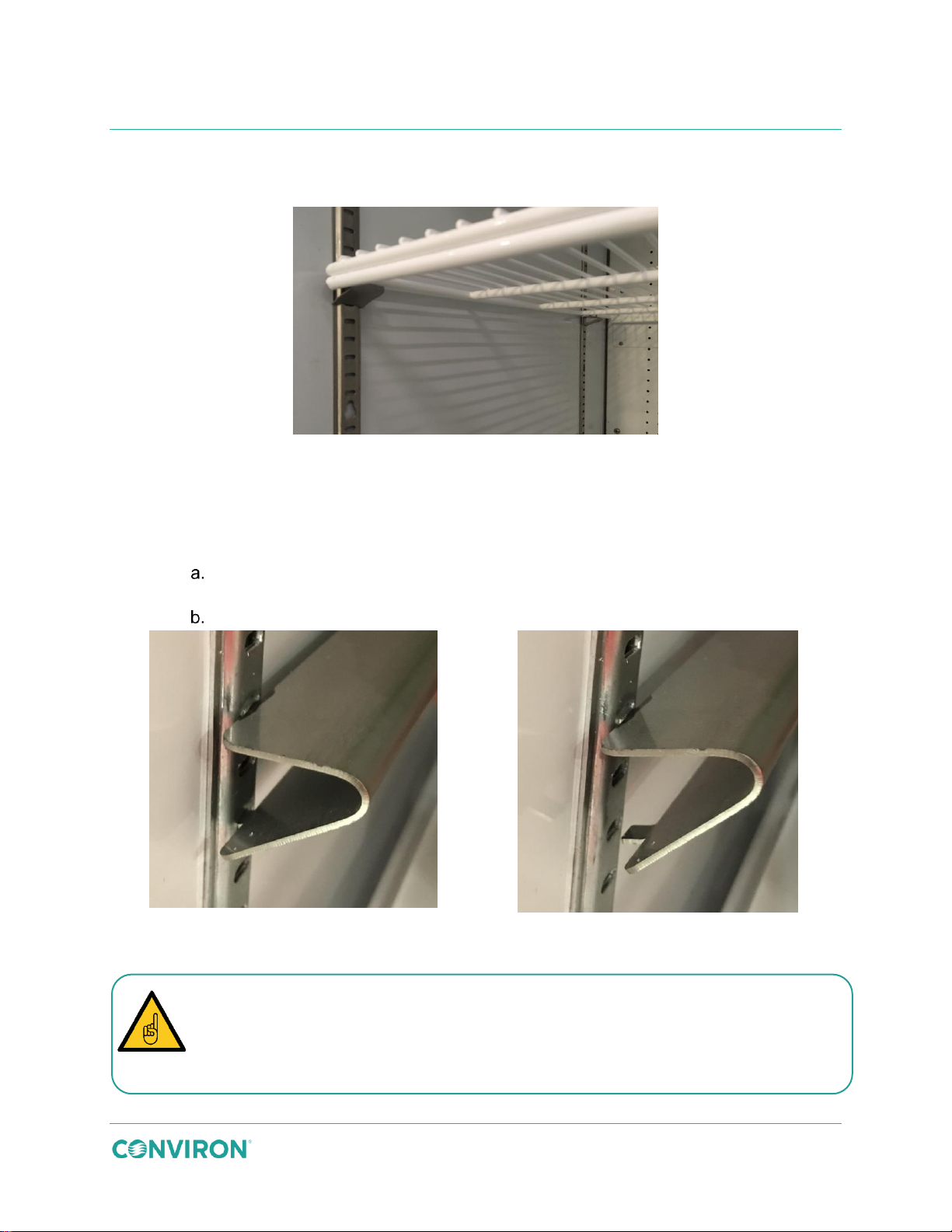
Ensure the clips are firmly seated into the slots in the pilaster before installing the wire
GEN1000 Operator Manual
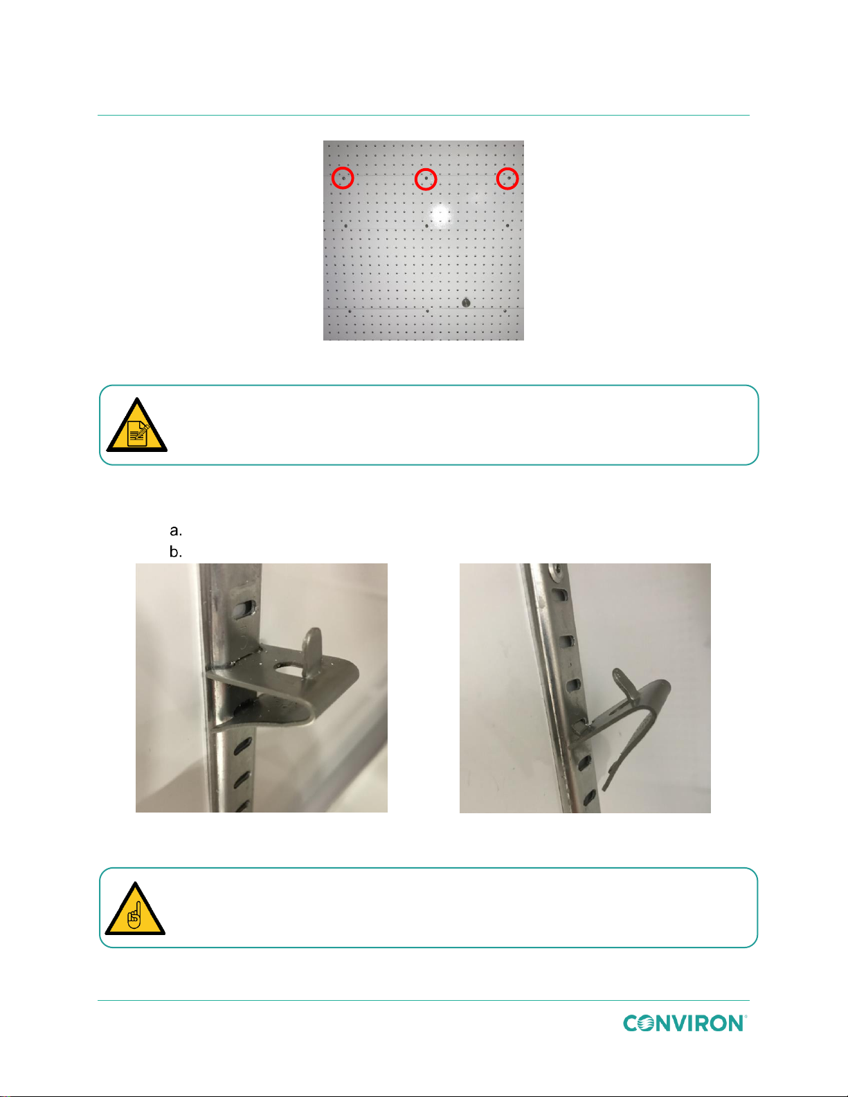
Figure 3-13 Cover Plate Screw Detail
3. Starting at the bottom of the chamber, install the shelf-clips (Figure 3-14) for the
appropriate number of shelves and to achieve the required growth height.
Insert the angled top tab of the shelf-clip into the pilaster at the required level.
Squeeze the clip to align the bottom straight tab with the slot in the pilaster.
Figure 3-14 Install the Shelf Clips
shelf. Incorrectly installed shelf clips could cause the shelf to collapse.
18 July 22, 2019 | 287960-ENG | R00
Page 29
Installation
Correct
Incorrect
Ensure the canopy support brackets are firmly seated into the slots in the pilaster and
4. Install a wire shelf on top of the wire shelf clips. Be careful not to scratch the painted
white finish (Figure 3-15).
Figure 3-15 Shelf Installed onto Clips
5. Repeat steps 3 and 4 for the remaining clips and shelves.
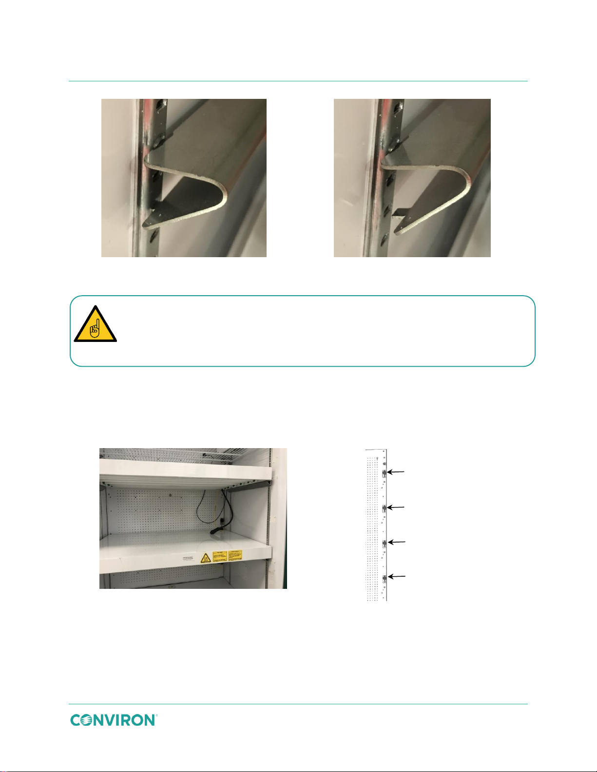
6. Install the canopy support brackets (Figure 3-16) for the appropriate number of
canopies and to achieve the required growth height.
Insert the angled top tab of the canopy support bracket into the pilaster at the
required level.
Squeeze the bracket to align the bottom straight tab with the slot in the pilaster.
Figure 3-16 Install the Canopy Support Brackets
that the canopy support is level and secure before installing the canopy.
Incorrectly installed canopy support brackets could cause the canopy to collapse.
July 22, 2019 | 287960-ENG | R00 19
Page 30
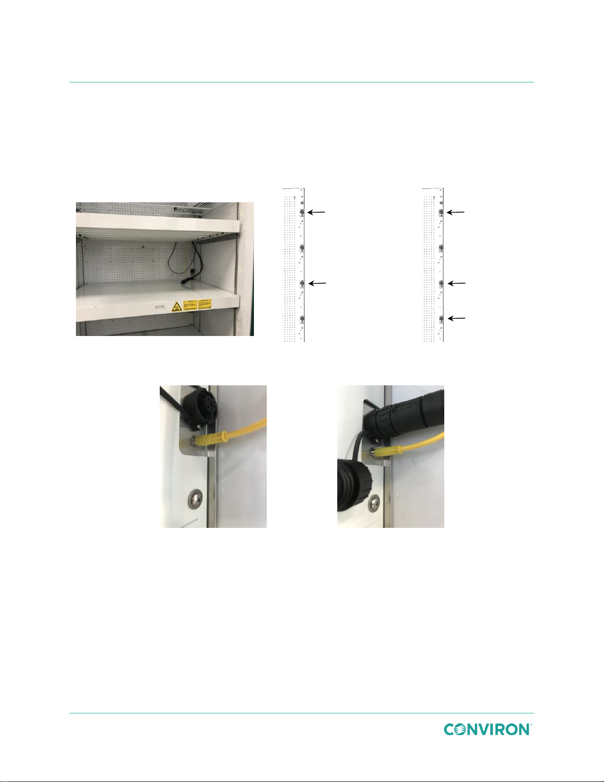
Figure 3-17 Install the Canopies
Figure 3-18 SH Canopies
Figure 3-19 SH X-Tier
Figure 3-20 Control Connection
Figure 3-21 Power Connection
Canopy 1
Canopy 2
Canopy 1
Canopy 2
Canopy 3
GEN1000 Operator Manual
7. Place the canopy onto the canopy support brackets. Ensure the connection cables
are on the right-hand side of the chamber (Figure 3-17). Repeat each additioanl
canopy as required.
8. To ensure safe and efficient operation of the canopy, the control and power cables
must be plugged into the correct receptacles, as shown in Figure 3-18 and Figure
3-19.
9. Plug the yellow canopy control cable into the small receptacle on the right-hand side
of the chamber (Figure 3-20).
10. Unscrew the receptacle protective cover and plug the black canopy power cable plug
into the large receptacle on the right-hand side of the chamber (Figure 3-21).
20 July 22, 2019 | 287960-ENG | R00
Page 31
Installation
43.5″ (110.5cm)
growth height
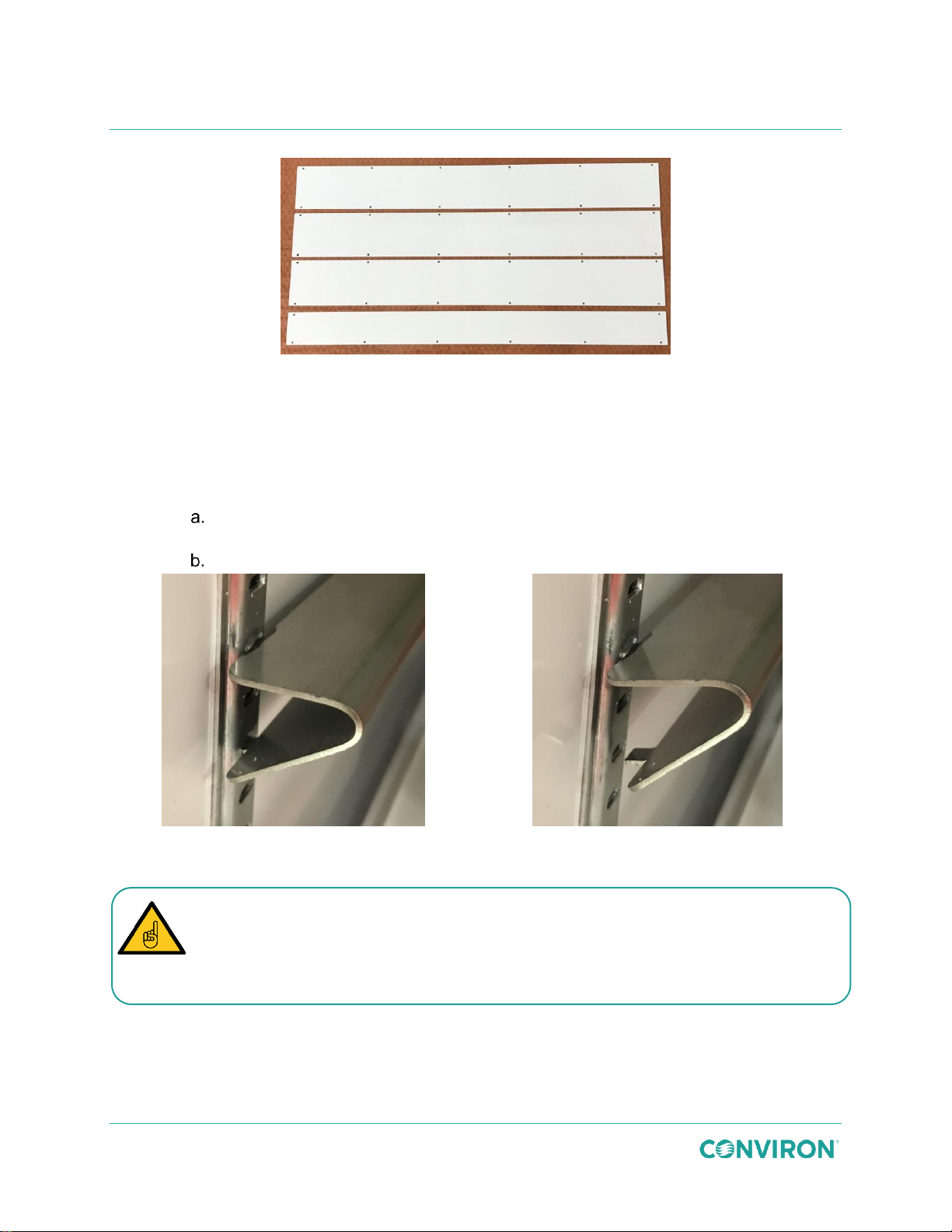
The cover plates are not all interchangeable. The three large plates, shown at the
opening.
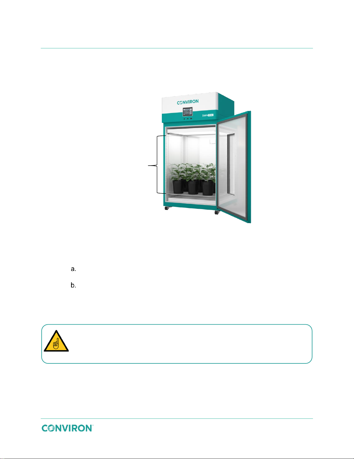
3.6.2 TA Configuration
The TA configuration uses solid plenum cover plates and a perforated floor to direct the airflow
upward through the plant material.
Figure 3-22 TA Configuration
To install the TA configuration kit:
1. Close the air flow from the plenum.
Loosen the 12 bolts around the perimeter of the plenum, and then turn the
center locking knob counter-clockwise to loosen it.
Use the knob to slide the plenum up, tighten the knob, and then re-tighten the
12 bolts around the perimeter.
2. Use 12 screws to attach each solid cover plate to the rear wall, covering the openings
in the rear wall.
top of Figure 3-23, must be installed over the top three openings. The small cover
plate, shown at the bottom of Figure 3-23, must be installed over the bottom
July 22, 2019 | 287960-ENG | R00 21
Page 32
Correct
Incorrect
Ensure the canopy support brackets are firmly seated into the slots in the pilaster and
Incorrectly installed canopy support brackets could cause the canopy to collapse.
GEN1000 Operator Manual
Figure 3-23 Solid Cover Plates
3. Install the Unifloor. Air will flow upward through the unifloor into the chamber.
4. Install the canopy support brackets (Figure 3-24) for the appropriate number of
canopies and to achieve the required growth height.
Insert the angled top tab of the canopy support bracket into the pilaster at the
required level.
Squeeze the bracket to align the bottom straight tab with the slot in the pilaster.
Figure 3-24 Install the Canopy Support Brackets
that the canopy support is level and secure before installing the canopy.
22 July 22, 2019 | 287960-ENG | R00
Page 33
Installation
Figure 3-25 Install the Canopies
Figure 3-26 TA Canopy Connection
Figure 3-27 Control Connection
Figure 3-28 Power Connection
Canopy 1
5. Place the canopy onto the canopy support brackets. Ensure the connection cables
are on the right-hand side of the chamber (Figure 3-25).
6. To ensure safe and efficient operation of the canopy, the control and power cables
must be plugged into the correct receptacles, as shown in Figure 3-26.
7. Plug the yellow canopy control cable into the small receptacle on the right-hand side
of the chamber (Figure 3-27).
8. Unscrew the receptacle protective cover and plug the black canopy power cable plug
into the large receptacle on the right-hand side of the chamber (Figure 3-28).
July 22, 2019 | 287960-ENG | R00 23
Page 34
6.5″ (16.5cm)
growth height
The cover plates are not all interchangeable. The three flat plates, shown at the top
, must be installed
over the bottom opening.
GEN1000 Operator Manual
3.6.3 TC Configuration
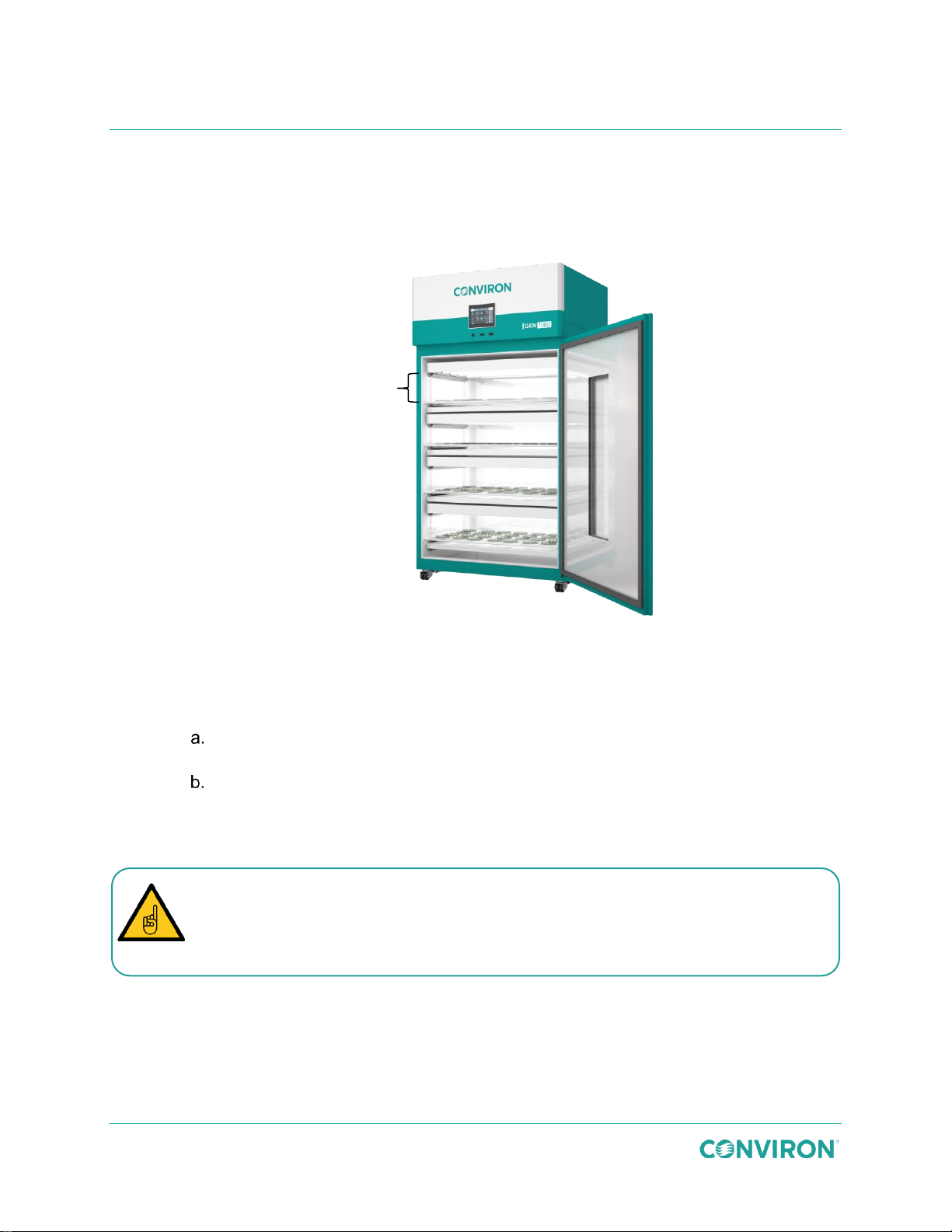
The TC kit distributes air vertically through the individual air-shelves to minimize condensation
within petri dishes and containers. Arrange the air-shelves and light canopies to provide a
growth height of 6.5″ (16.5cm).
Figure 3-29 TC Configuration
To install the TC configuration kit:
1. Close the air flow from the plenum.
Loosen the 12 bolts around the perimeter of the plenum, and then turn the
center locking knob counter-clockwise to loosen it.
Use the knob to slide the plenum up, tighten the knob, and then re-tighten the
12 bolts around the perimeter.
2. Use 12 screws to attach each slotted cover plate to the rear wall, covering the
openings in the rear wall.
of Figure 3-30, must be installed over the top three openings. The cover plate with
the bottom flange and gasket, shown at the bottom of Figure 3-30
24 July 22, 2019 | 287960-ENG | R00
Page 35
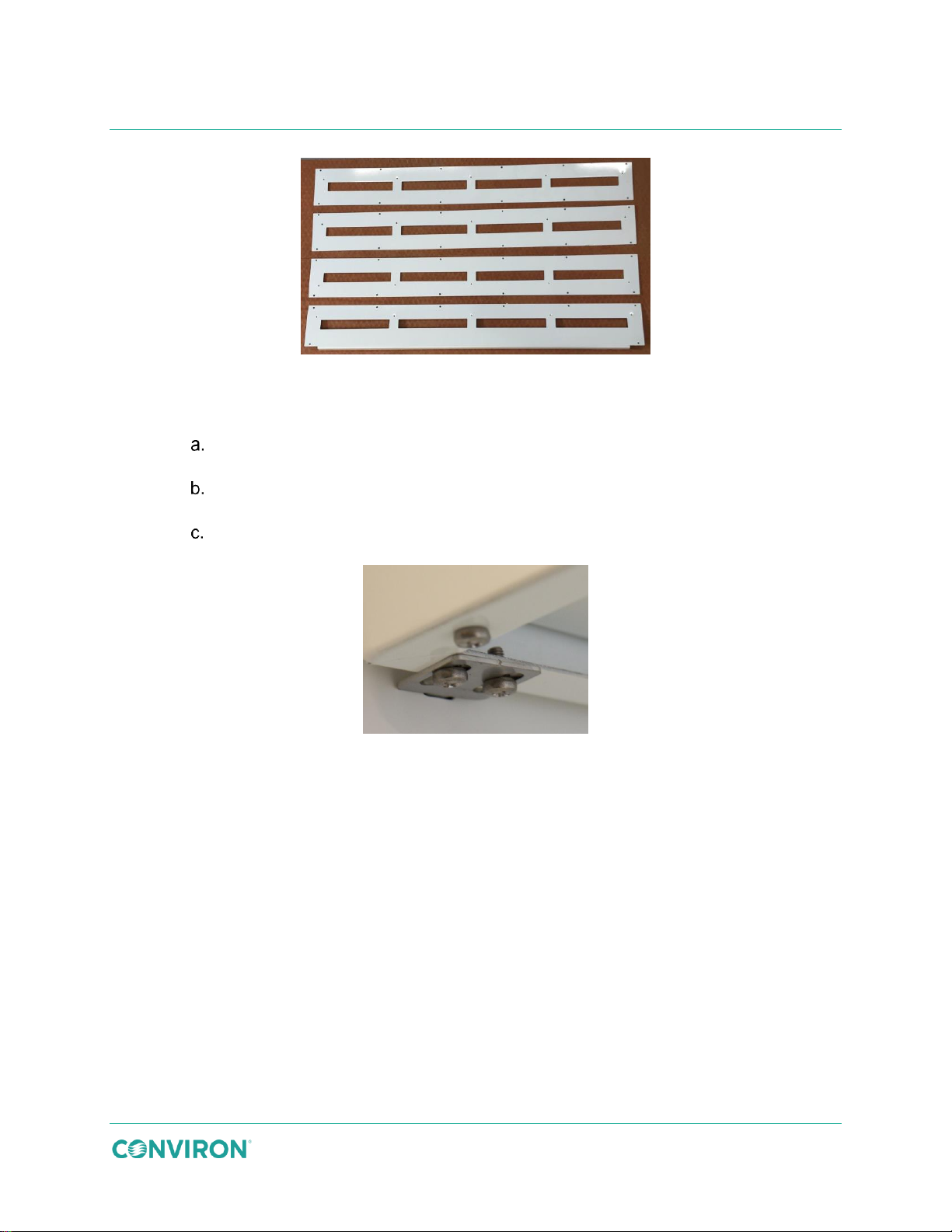
3. Install an air shelf.
Starting at the bottom, place the bottom-rear lip into the slats in the cover plate.
Line up the holes by shifting the shelf left/right as needed.
Hold the shelf level and place the left and right brackets into the appropriate
slots in the pilaster.
Using a ratchet, and working from underneath the shelf, fasten the brackets to
the shelf.
Installation
Figure 3-30 Slotted Cover Plates
Figure 3-31 Air Shelf Bracket
4. Secure the air shelf to the cover plate.
5. Install wire shelf clips into the pilaster using the notch immediately above the air shelf.
6. Secure a wire shelf on top of the wire shelf clips. Be careful not to scratch the white
finish.
July 22, 2019 | 287960-ENG | R00 25
Page 36
Correct
Incorrect
Ensure the canopy support brackets are firmly seated into the slots in the pilaster and
Incorrectly installed canopy support brackets could cause the canopy to collapse.
GEN1000 Operator Manual
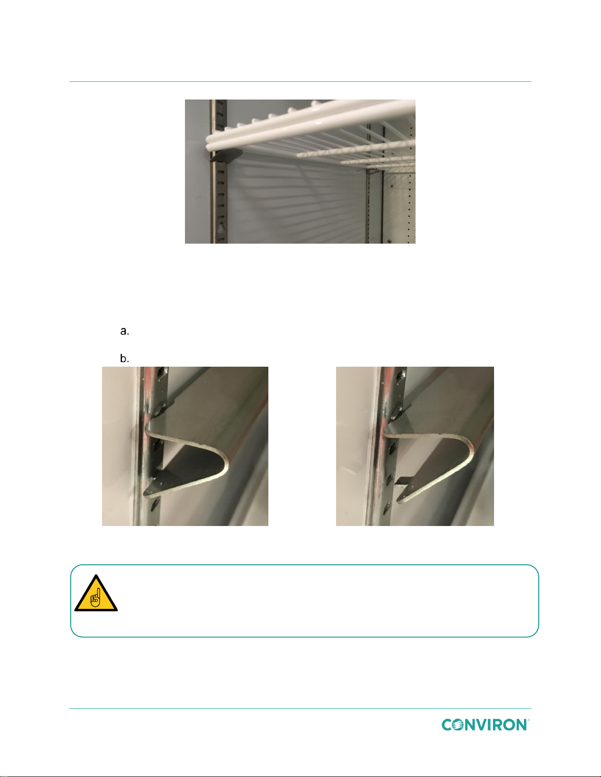
Figure 3-32 Shelf Installed onto Clips
7. Repeat steps 3 through 6 for the remaining shelving units.
8. Install the canopy support brackets (Figure 3-33) for the appropriate number of
canopies and to achieve the required growth height.
Insert the angled top tab of the canopy support bracket into the pilaster at the
required level.
Squeeze the bracket to align the bottom straight tab with the slot in the pilaster.
Figure 3-33 Install the Canopy Support Brackets
that the canopy support is level and secure before installing the canopy.
26 July 22, 2019 | 287960-ENG | R00
Page 37
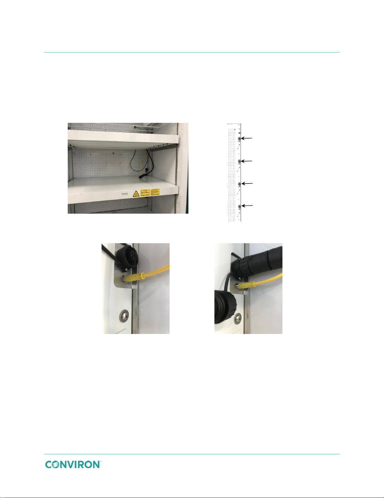
9. Place the canopy onto the canopy support brackets. Ensure the connection cables
Figure 3-34 Install the Canopies
Figure 3-35 TC Canopy Connection
Figure 3-36 Control Connection
Figure 3-37 Power Connection
Canopy 1
Canopy 3
Canopy 4
Canopy 2
are on the right hand side of the chamber (Figure 3-34). Repeat for each additional
canopy as required.
10. To ensure safe and efficient operation of the canopy, the control and power cables
must be plugged into the correct receptacles, as shown in Figure 3-35.
Installation
11. Plug the yellow canopy control cable into the small receptacle on the right-hand side
of the chamber (Figure 3-36).
12. Unscrew the receptacle protective cover and plug the black canopy power cable plug
into the large receptacle on the right-hand side of the chamber (Figure 3-37).
13. Repeat steps 8 through 11 for each remaining canopy.
July 22, 2019 | 287960-ENG | R00 27
Page 38
8.5″ (21.6cm)
growth height
8.5″ (21.6cm)
growth height
12.5″ (31.75cm)
growth height
12.5″ (31.75cm)
growth height
The chamber is shipped with the plenumn open by default. To confirm that the
Look through the perforated holes. If you can see through them, the plenum is open.
If not, the plenum is closed.
GEN1000 Operator Manual
3.6.4 IN Configuration
The IN kit uses perforated cover plates to distribute airflow horizontally across multiple shelves
from back to front.
Figure 3-38 IN Configuration
To install the IN configuration kit:
1. Confirm that air flow through the plenum is open (Figure 3-39). The plenum must be
open for air to flow correctly in the IN configuration.
plenum is open, do one of the following;
Confirm that the center locking knob (Figure 3-39) on the rear wall of the chamber is
in the down position.
OR
2. Use 12 screws to attach each SH cover plate to the rear wall, covering the openings
in the rear wall (Figure 3-41).
28 July 22, 2019 | 287960-ENG | R00
Page 39
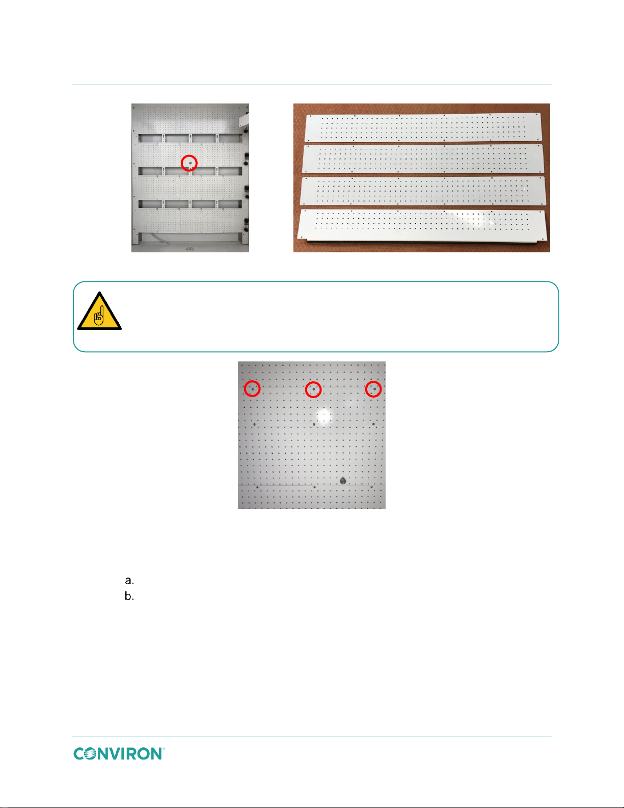
Figure 3-39 Open Plenum
Figure 3-40 Perforated Cover Plates
The cover plates are not all interchangeable. The three flat plates, shown at the top of
bottom opening.
Installation
Figure 3-40 must be installed over the top three openings. The cover plate with the
flange and the gasket, shown at the bottom of Figure 3-40 must be installed over the
Figure 3-41 Cover Plate Screw Detail
3. Starting at the bottom of the chamber, install the shelf clips (Figure 3-42) for the
appropriate number of shelves to achieve the required growth height.
Insert the angled top tab of the shelf clip into the pilaster at the required level.
Squeeze the clip to align the bottom straight tab with the slot in the pilaster.
July 22, 2019 | 287960-ENG | R00 29
Page 40
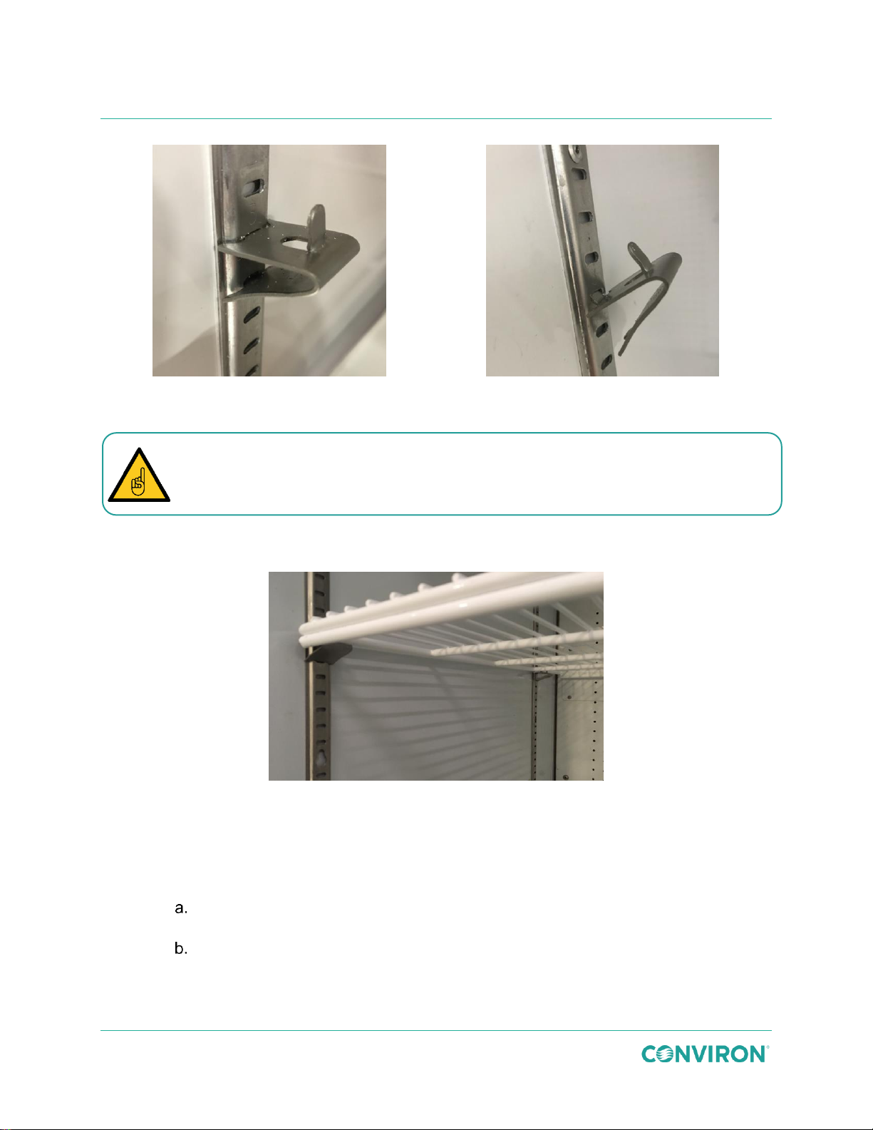
Correct
Incorrect
Ensure the clips are firmly seated into the slots in the pilaster before installing the wire
GEN1000 Operator Manual
Figure 3-42 Install the Shelf Clips
shelf. Incorrectly installed shelf clips could cause the shelf to collapse.
4. Install a wire shelf on top of the wire shelf clips. Be careful not to scratch the painted
white finish (Figure 3-43).
Figure 3-43 Shelf Installed onto Clips
5. Repeat steps 3 and 4 for the remaining clips and shelves.
6. Install the canopy support brackets (Figure 3-44) for the appropriate number of
canopies to achieve the required growth height.
Insert the angled top tab of the canopy support bracket into the pilaster at the
required level.
Squeeze the bracket to align the bottom straight tab with the slot in the pilaster.
30 July 22, 2019 | 287960-ENG | R00
Page 41
Installation
Correct
Incorrect
Figure 3-45 Install the Canopies
Figure 3-46 IN Canopy Connection
Canopy 1
Canopy 3
Canopy 4
Canopy 2
Incorrectly installed canopy support brackets could cause the canopy to collapse.
Figure 3-44 Install the Canopy Support Brackets
Ensure the canopy support brackets clips are firmly seated into the slots in the
pilaster and that the canopy support is level and secure before installing the canopy.
7. Place the canopy onto the canopy support brackets. Ensure the connection cables
are on the right-hand side of the chamber (Figure 3-45). Repeat for each additional
canopy as required.
8. To ensure safe and efficient operation of the canopy, the control and power cables
must be plugged into the correct receptacles, as shown in Figure 3-46.
July 22, 2019 | 287960-ENG | R00 31
Page 42
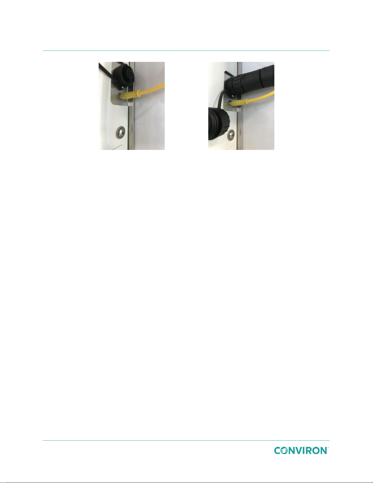
Figure 3-47 Control Connection
Figure 3-48 Power Connection
GEN1000 Operator Manual
9. Plug the yellow canopy control cable into the small receptacle on the right-hand side
of the chamber (Figure 3-47).
10. Unscrew the receptacle protective cover and plug the black canopy power cable plug
into the large receptacle on the right-hand side of the chamber (Figure 3-48).
11. Repeat steps 8 through 10 for each remaining canopy.
3.7 Remove the Light Canopies and Shelves
Prior to installing a new configuration kit, the existing configuration kit must be removed. Retain
all associated fasteners, clips, bracket, shelves, cover plates, and canopies for future use.
3.7.1 Remove a Wire Shelf
1. Lift the shelf up away from the shelf clips.
2. Remove it from the chamber.
3.7.2 Remove a Wire Shelf Clip
1. Tilt the clip upwards to remove the bottom tab from the pilaster.
2. Continue tilting the clip upwards to unhook the top of the clip from the pilaster.
3.7.3 Remove an Air Shelf
1. Use a #2 Phillips screwdriver to remove the screw securing the bracket to the shelf.
2. Remove the brackets from the pilaster.
3. Support the front end of the shelf with one hand, and with the other hand, remove the
screws that secure the shelf to the plenum.
4. Continue supporting the front of the shelf, and lift the back of the shelf to separate it
from the cover plate.
5. Remove the shelf from the chamber.
32 July 22, 2019 | 287960-ENG | R00
Page 43
Installation
6
1
2
3 4 5
3.7.4 Remove an Air Shelf Bracket
1. Use a #2 Phillips screwdriver to remove the screws from the clips.
2. Tilt the clip upwards to unhook the top of the bracket.
3.7.5 Remove the Unifloor
The Unifloor is held in place by screws that hook into matching holes along the back of the
chamber.
1. Lift up the front of the Unifloor.
2. Slide the back of the Unifloor up to disengage the screws that are holding it in place.
3. Remove the floor from the chamber.
3.7.6 Remove a Cover Plate
1. Using a Phillips bit, remove the screws that secure the cover plate to the plenum.
2. Remove the cover plate from the chamber.
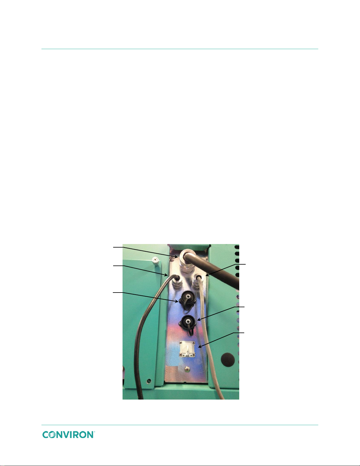
3.8 Connect the UPS, Communication, and Central Alarm Contacts
Connect the UPS, communication, customer alarm, and condensate pump connectors to the
ports on the rear of the chamber as shown in Figure 3-49 and described in Table 3-2.
Figure 3-49 Back Panel Connections
July 22, 2019 | 287960-ENG | R00 33
Page 44
Item
Description
Usage
1
Power Cord
Plug the power cord into a receptacle on a
dedicated circuit after all other connections have
been made.
2
A/C Power to UPS
The UPS has two connection cables. One is power
to the UPS and the other is power from the UPS to
the control system. The plug and receptacle are
keyed and dedicated to the UPS and are not be
used for any other purpose.
3
Backup A/C Power From UPS
4
Central Alarm Contact (CAC)
The receptacle is dedicated for the CAC connection.
The receptacle is mated with the plug and then
screwed tightly together.
5
Optional Condensate Pump Connection
This receptacle is dedicated for the drain pan pump
which is a purchasable option. The plug is mated
with the receptacle and then screwed tightly
together.
6
RJ-45 Communications Port
Connect an RJ-45 terminated cable to the facility
network.
A power cord plug end is not supplied with the product on 50 Hz models. The cord
person.
Observe the following precautions when handling the 60 Hz power cord:
GEN1000 Operator Manual
Table 3-2 Back Panel Connection Descriptions
The Central Alarm Contact is rated for 230VAC at 0.5 amperes.
3.9 Connect the Electrical Cord
All power and grounding connections must be made in accordance with this manual and local
regulations.
end supplied by the client must be wired in accordance with applicable electrical
codes. Hot, neutral, and ground connections must be verified by a locally qualified
Handle the power cord carefully and protect it from damage.
Hold the plug when unplugging the power cord. Do not pull on the cord.
Do not handle the power cord with wet hands.
Do not bend or modify the ground pin.
Plug the power cord into a receptacle on a dedicated circuit after all other connections have
been made.
34 July 22, 2019 | 287960-ENG | R00
Page 45
4 START UP
Before powering ON, ensure all local, municipal, and facility inspections are complete.
Once the chamber is assembled, leveled, and all connections have been made, turn on the
power to the chamber. Ensure that the chamber is operating properly before introducing any
research material.
4.1 Power ON
Before powering ON, ensure all mechanical, fluid, communication, and electrical
connections are secure.
Before powering ON, ensure that no service or other personnel are performing work
on the cabinet.
Ensure the chamber is level and stable before operating.
4.1.1 Start-Up Procedure
1. Ensure the mains breaker is ON.
2. Ensure the power cord is plugged into a receptacle on a dedicated circuit.
3. Ensure that all drain, water, and CO2 lines are connected.
4. For a water-cooled condensing unit, open the manual bypass valve for constant flow
supply, close the bypass valve for variable flow supply, or adjust the bypass valve as
required during water system balancing.
5. Turn the power switch on the front of chamber to ON.
Do not turn the control system off during boot up.
6. With the control system powered up, set and run a program. Refer to the supplied
control system manual for further details.
July 22, 2019 | 287960-ENG | R00 35
Page 46
Operate your Conviron equipment for a few days before introducing any plant
equipment meets the requirements for your experiments.
GEN1000 Operator Manual
4.2 Visual Checks
1. Confirm that all lights function when turned on and that the doors are light-tight.
2. Inspect the doors with interior lights on, in a darkened room.
Refer to the Conviron Chambers Maintenance & Troubleshooting Manual for more information.
material. This acquaints you with the equipment’s operation and ensures the
36 July 22, 2019 | 287960-ENG | R00
Page 47
5 OPERATION
Warning: Optical radiation hazard
Do not look directly at the lights even while wearing protective glasses.
The following description and instructions provide an overview of basic operation of the
chamber.
5.1 Control and Monitoring
The GEN1000 comes equipped with Conviron’s CMP6060 controller, which includes powerful
programming and reporting capabilities through a full-color, high resolution touchscreen with an
intuitive graphic interface. Users can create custom programs for key parameters such as
temperature, lighting and humidity and receive audible, visual and e-mail notifications of alarms.
Options include connection to your local area network (LAN) and connectivity to a central PC or
mobile device with Conviron Central Management™. CMPLink allows integration with an Argus
Control System.
Refer to the CMP6060 Control System Manual for a complete description and operating
instructions.
5.2 Fluorescent and LED Lighting
The standard lighting systems for the GEN1000 use high efficiency T5 fluorescent lamps
configured to suit the intensity required for each application and kit. Lamp and ballast
combinations have been designed to ensure uniform light distribution. Standard lighting in the
TA and SH kits can be adjusted in levels; for all kits, options for dimming through the controller
are available.
All lighting control outputs are logged to determine how long the lights have been on. Operators
can set a ″warning″ message to pop up at the controller as a reminder.
Refer to the lamp manufacturer’s specifications for more detailed information.
The lighting system in this product produces potentially dangerous ultraviolet and
infrared radiation in close proximity.
Exposed body parts should be covered within 8” or 200mm of the lighting. Always
wear protective clothing such as gloves and long sleeve shirts when working within
the chamber.
Always wear protective glasses when working within the chamber. Glasses should
be CSA Z94.3-07 or ANSI Z87.1-2010 compliant, such as with Steele THT416AFG
or equivalent and block 99.9% of UVA/UVB/UVC rays.
July 22, 2019 | 287960-ENG | R00 37
Page 48
Warning: Burn hazard
burnt out tubes.
GEN1000 Operator Manual
Potential injury could result from contact with the hot light canopies or lamps.
The lamp ends near the sockets produce enough heat to cause skin burns.
Do not touch the lamps while in operation. Allow the lamps to cool before changing
5.3 Lighting Options
The chamber can be equipped with several different lighting configurations. Programmable
ranges depend on the light type selection and choice of dimming or levels control.
5.3.1 Fluorescent Lighting
The standard lighting configuration consists of fluorescent lamps to provide a balanced
spectrum for plant growth. The lighting is programmable in steps, dimmable from 10% to 100%
of maximum output.
The fluorescent tubes are individually replaceable, as required.
5.3.2 LED Lighting – LED Option
LED lighting offers significant advantages over the fluorescent lighting packages, including:
Decreased wattage consumption, which yields significant energy savings.
Reduced overall maintenance costs due to the longer life of LEDs.
Reduced heat production during operation, which reduces demand on the cooling
system and allows the light to be closer to the plants.
Reduced sensitivity to temperature variations.
LED tubes are not compatible with GEN1000 fluorescent canopies. Conversely,
fluorescent lamps are not compatible with GEN1000 LED canopies.
Contact Conviron for LED tube replacement.
5.3.3 Closed Loop Dimmable Lighting System
Lamp canopies incorporate dimmable ballasts. Automatic adjustment of the light intensity can
be set within the programmed range for as low as 10% for fluorescent and 10% for LED.
Prior to operating dimmable fluorescent lamps, run the lamps at full intensity for a period of 100
hours to burn off impurities on the filament ends of the lamps left during manufacturing process.
38 July 22, 2019 | 287960-ENG | R00
Page 49
Operation
Failure to burn in the fluorescent lamps before dimming will significantly reduce the life
of the tubes.
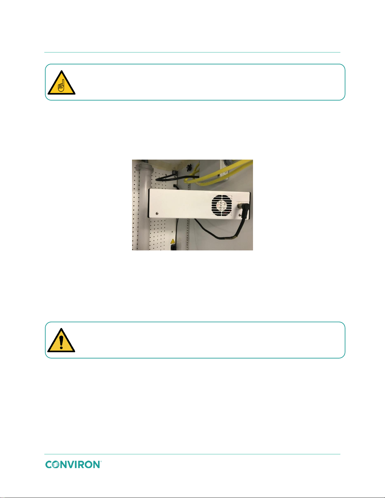
5.4 Aspirator
Located in the growth area, the aspirator houses the sensors used to monitor temperature and
humidity levels within the chamber. The aspirator receives an air sample from the room to
measure and control conditions and provides shielding from the chamber lighting to prevent
false readings caused by radiant energy.
Figure 5-1 Aspirator
5.5 Instrumentation Port
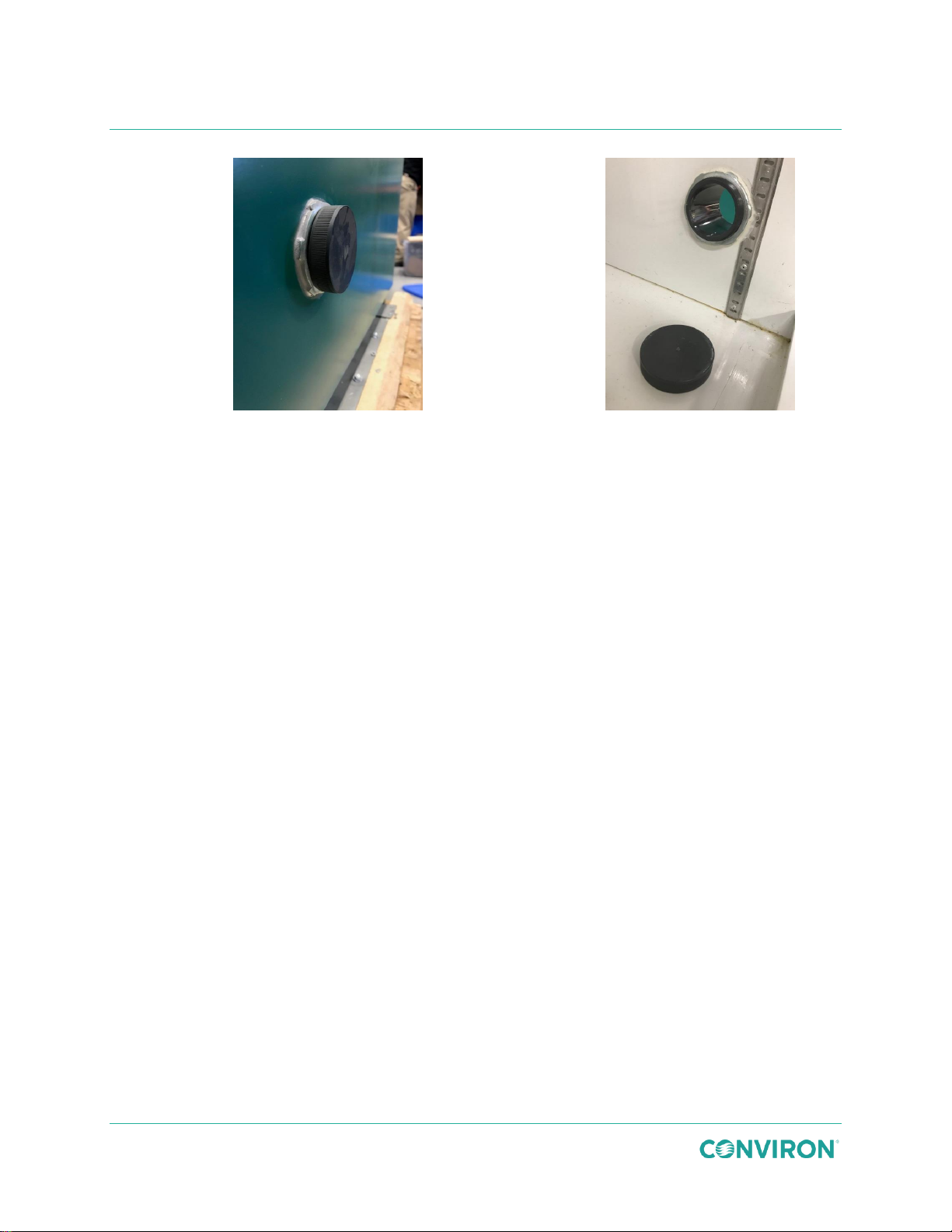
The instrumentation port with a threaded closure is located on the lower-right side of the
chamber (Figure 5-2). The port enables instrument probes, and small hoses, etc. to be passed
through the wall of the cabinet for connection to equipment within the cabinet growth
environment.
The instrumentation port is intended for low-voltage wires only. Conviron does not
recommend the use of extension cords inside the chamber.
July 22, 2019 | 287960-ENG | R00 39
Page 50
Exterior View
Interior View
Figure 5-2 Instrumentation Port Location
GEN1000 Operator Manual
5.6 Fresh Air Inlet and Exhaust Ports
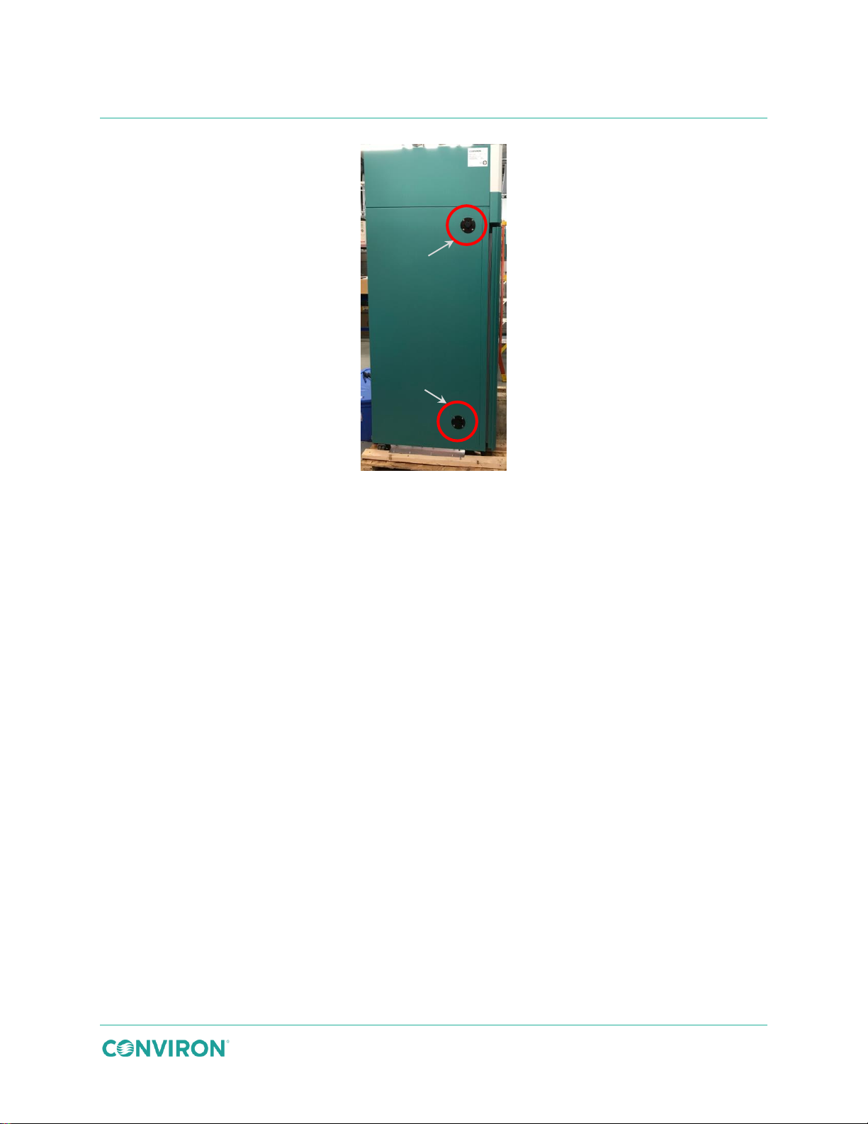
The fresh air inlet allows the operator to manually adjust the rate at which fresh air is introduced
into the chamber. The adjustment knob is located on the lower-left side of the chamber and can
be adjusted from fully closed (no fresh air) to fully open to allow up to 20 ft3/min (0.57m3/min) of
air exchange.
The fresh air inlet assembly contains a foam filter to help prevent light, dust, and larger
particulate matter from entering the growth area. This filter should be cleaned monthly to
prevent a build-up of foreign material that could restrict airflow. Refer to the Conviron Chambers
Maintenance & Troubleshooting Manual for more information.
Fresh air is drawn into the bottom of the chamber through the inlet port by the chamber’s
variable speed fan located in the ceiling compartment, and then the chamber air is exhausted
through the top exhaust port (Figure 5-3).
40 July 22, 2019 | 287960-ENG | R00
Page 51
Inlet
Exhaust
Operation
Figure 5-3 Fresh Air Inlet and Exhaust Port Location
5.7 Fan Speed Control
Fan speed is user-adjustable between the preset minimum and the maximum allowable fan
rpm.
To adjust the fan speed:
Refer to the supplied control system manual for a complete description and operating
instructions.
5.8 Plant Placement
Depending on the chamber configuration, a wide variety of plant growth options are available,
from seed to full maturity, and for short to medium and tall plant species.
Plant pots or trays are placed directly on the wire shelves, or directly on the Unifloor in a TA
configuration.
The shelves can be installed in any position within the chamber, depending on the experiment
requirements. Refer to Section 3.6 Install the Light Canopies and Shelving Configuration Kits,
starting on page 15 for installation instructions.
5.9 Bypass Dehumidification – BDH Option
The Bypass Dehumidification (BDH) is an optional dehumidification system used to achieve
relative humidity setpoints below the resultant of ambient conditions and moisture load in the
cabinet. A precisely controlled volume of chamber air bypasses the heat exchanger by means of
a proportionally controlled air damper. Using the cooling system, moisture is removed from the
remaining air by cooling and reheating.
July 22, 2019 | 287960-ENG | R00 41
Page 52
Close the main valve on the CO2 tank when it’s not in use.
GEN1000 Operator Manual
5.10 Additive Carbon Dioxide Control – CO2 Option
The Carbon Dioxide control option provides additive control of CO2. It includes a sensor
connected to the control system and a solenoid controlled injection system to elevate CO2 levels
in the chamber.
The level of CO2 in the chamber is displayed in parts per million (ppm) on the control screen and
is programmed the same way as temperature and humidity. CO2 is monitored continuously as
long as the control system is active.
5.10.1 Set up the Additive CO2 Control
CO2 control requires a high-pressure and a low-pressure regulator. In most chambers, the lowpressure regulator and the solenoid assembly are located above in the machine compartment
and are factory set at 2 pounds per square inch (psi).
Do not adjust this setting.
The high-pressure regulator is located on the customer-supplied CO2 line. This regulator comes
in two styles of flow meters, a dial gauge or a glass tube and ball style. In North America,
Conviron provides the high-pressure regulator. Outside North America, the customer supplies
the high-pressure regulator due to different thread sizes on the CO2 line.
Do not adjust the regulator on the CO2 tank once it has been set up.
5.10.2 Adjust the CO2 Control
There are two variables to consider: programming desired CO2 concentration and control of air
flow through the chamber.
Programming the CO2 setpoint is as easy as programming temperature or relative humidity.
Values are entered in parts per million in the CO2 zone on the Main Status Program Screen of
the control system. The Vaisala™ CO2 monitor operates in two ranges, up to 2000 ppm and up
to 3000 ppm.
Customized ranges are available upon written request. Contact Conviron for more
information.
Ambient CO2 levels are usually at least 350 ppm and can be higher, depending on proximity to
other CO2 sources such as human beings or automobiles. The CO2 concentration in the
42 July 22, 2019 | 287960-ENG | R00
Page 53

Operation
chamber can never be less than the ambient concentration because CO2 control is additive
only.
Closing fresh air into and exhausting air out of the chamber is important to achieving desired
CO2 concentrations. Failure to consider this will lead to undesired results.
To adjust the CO2 control:
Refer to the supplied control system manual for a complete description and operating
instructions.
5.11 Central Management System – CMS Option
Refer to the supplied central management manual for a complete description and operating
instructions.
5.12 Shutdown
In the event that the chamber will not be used for a period of up to and including 14 days, it is
best to keep it running, with the temperature at or near ambient and with only the fans running.
If experiments will not be run for a period of longer than 14 days, to minimize unnecessary
electricity consumption, ensure all plants and soil are removed from the growth area, and clean
the unit as described in the Conviron Chambers Maintenance & Troubleshooting Manual. Open
the fresh air inlet and exhaust ports and leave the chamber and observation doors slightly open
to reduce moisture buildup.
July 22, 2019 | 287960-ENG | R00 43
Page 54

GEN1000 Operator Manual
44 July 22, 2019 | 287960-ENG | R00
Page 55
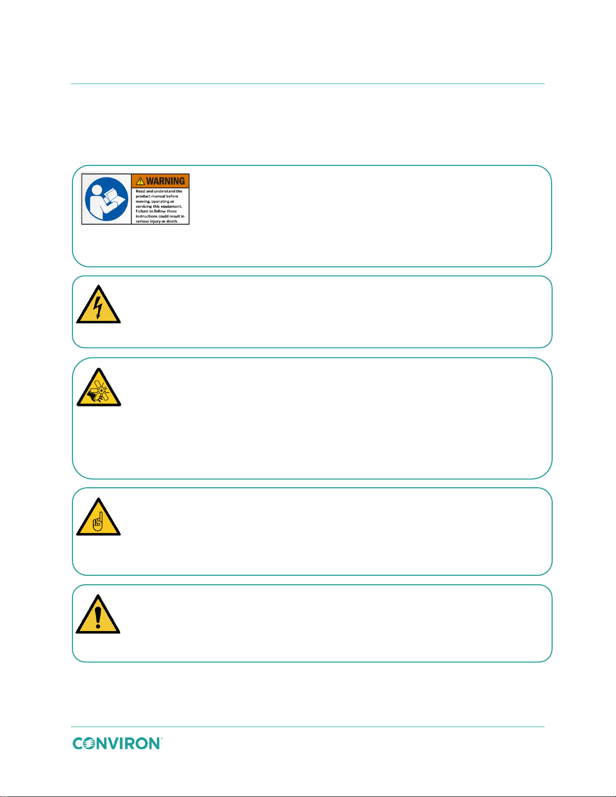
6 MAINTENANCE
Warning: Read and understand the product manuals before moving,
followed before working with the product.
Warning: Electrical shock hazard during maintenance or service.
maintenance or service on this chamber.
Warning: Rotating blade hazard
the machine compartment is open and power is connected.
Only qualified trades or facility personnel, who have read and completely understand
operation and/or maintenance of the equipment.
Warning: Potential hand injury
The machine compartment, which is not user accessible, may include a fan without a
Do not contact the sharp edges of the fan compartment.
The GEN1000 chamber requires regular maintenance in order to continue performing to
specifications.
installing, operating, or servicing this equipment.
Failure to follow these instructions could result in equipment damage,
serious personal injury, or death.
The manual contains safety information that must be understood and
Serious personal injury or death could result from contacting live electrical circuits.
Turn the power to the chamber OFF at the mains panel before performing
Opening the access panel results in exposure to rotating fan blades. Serious
personal injury could result from contact with the rotating fan blades.
Remove power from the chamber before servicing. Do not perform maintenance
within the machine compartment with the power connected. The condenser fans on
air-cooled units have exposed fan blades which are a hazard when the top cover of
these instructions, should perform the required installation work following acceptable
safety standards.
Contact the responsible party, or Conviron, immediately if in doubt about safe
guard. Contact with the sharp edges of the fan could result in lacerations.
July 22, 2019 | 287960-ENG | R00 45
Page 56
Warning: Burn hazard
The refrigeration system components and heater element become hot during normal
before service.
Warning: Potential user injury after service
after service.
Warning: Burn hazard
temperatures and present a burn hazard.
GEN1000 Operator Manual
Personal injury could result from contacting hot surfaces within the chamber.
operation.
Allow the hot refrigeration components and heater elements to cool to the touch
Personal injury to the users could result from not replacing the access panels after
service.
Ensure the access panels are replaced and secure before operating the chamber
6.1 Disconnect the Power Before Maintaining or Servicing the Chamber
To maintain or service this chamber, it is necessary to disconnect it from power.
1. Turn the chamber power off by moving the toggle switch on the front panel to the
OFF position, as indicated by the symbol.
2. Press and hold the UPS button until the power shuts off. Verify that all three LED
indicators are off.
3. Turn off and lock the building disconnect switch provided during the installation.
4. Remove the load plug from the UPS.
5. Verify the power is off between contacts L1A and NA after opening a service access
panel as an additional precaution.
6.2 Clean the Chamber
For interior cleaning, dampen a clean towel or rag outside the unit, and carefully wipe the unit
down. Do not use abrasive cleaners. Mild detergents solutions are suitable for most cleaning
requirements.
Use glass cleaner on both the interior and the exterior of the glass viewport window, if present.
6.3 Replace Fluorescent or LED Lamps
Inspect the lamps daily to ensure that all lamps are functioning properly and replace poorly lit or
flickering lamps to ensure unit performance. The frequency of lamp changes will be determined
by application.
Do not touch the ends of the lamp tubes. Fluorescent lamps operate at high
46 July 22, 2019 | 287960-ENG | R00
Page 57
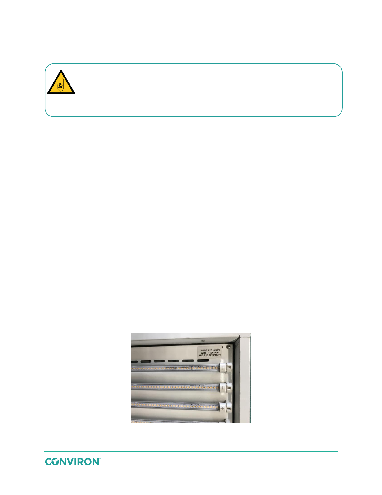
Maintenance
The LED bulbs and the fluorescent bulbs are physically similar with the same
output and may result in damage to the lamps and/or lamp canopy.
sockets. Read the lamp identification label on the canopy and ensure the correct
replacement lamp type is being installed. Mixing of LED and fluorescent lamps in a
fixture which is designed for LED only or fluorescent only will result in reduced light
To replace a fluorescent tube:
1. Identify the tube(s) to be replaced.
2. Turn the power to the chamber OFF. Refer to Section 6.1 Disconnect the Power
Before Maintaining or Servicing the Chamber on page 46 for instructions to turn off
the power.
3. Unlock the tube by rotating it one quarter turn and then carefully remove it from its
receptacle.
4. Install the new tube by inserting it fully into the correctly oriented lamp holders.
5. Secure the tube in place by rotating it one quarter turn.
6. Dispose of the used tube(s) following local requirements, or contact the local
authorities for proper disposal procedures.
To replace an LED tube:
1. Identify the tube(s) to be replaced.
2. Turn the power to the chamber OFF. Refer to Section 6.1 Disconnect the Power
Before Maintaining or Servicing the Chamber on page 46 for instructions to turn off
the power.
3. Unlock the tube by rotating it one quarter turn, and then carefully remove it from its
receptacle.
4. Install the new tube. Orient the positive end of the tube as described on the label on
the canopy (Figure 6-1).
Figure 6-1 LED Tube Orientation
July 22, 2019 | 287960-ENG | R00 47
Page 58
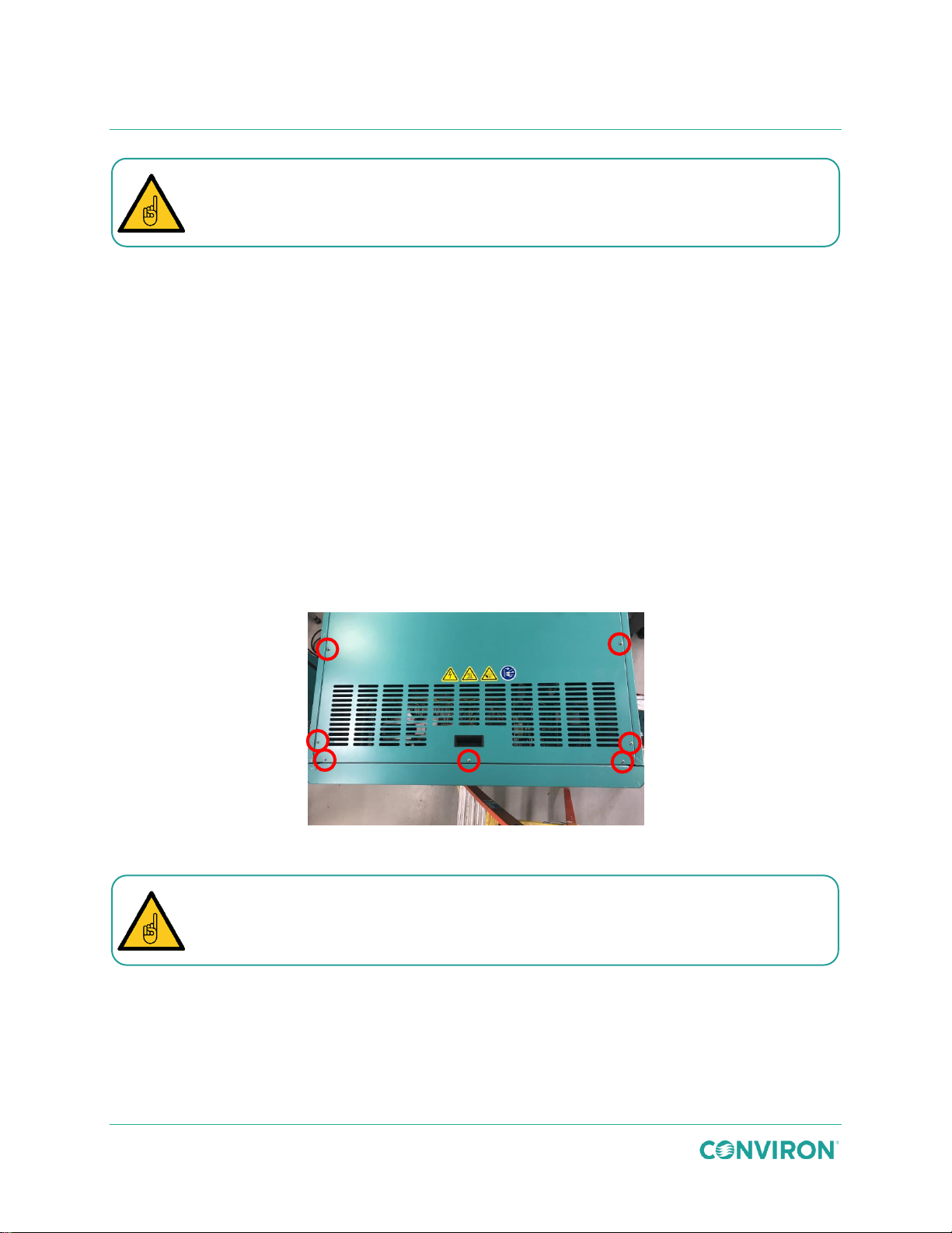
GEN1000 Operator Manual
Polarized LED tubes will not light up if installed incorrectly.
5. Secure the tube in place by rotating it one quarter turn.
6. Dispose of the used tube(s) following local requirements, or contact the local
authorities for proper disposal procedures.
6.4 Perform Maintenance in the Machine Compartment
The machine compartment is located on top of the chamber and should only be accessed by
qualified service technicians.
To perform maintenance in the machine compartment:
1. Turn the power to the chamber OFF. Refer to Section 6.1 Disconnect the Power
Before Maintaining or Servicing the Chamber on page 46 for instructions to turn off
the power.
2. Use a ladder to access to the top of the chamber. Do not stand on the chamber.
3. Remove the 12 screws, three on each of the four sides, from the perimeter of the top
compartment cover (Figure 6-2).
Figure 6-2 Remove the Screws from the Top Cover
Take care when removing and re-installing the top cover screws to avoid stripping
the screw threads. Do not use a high torque setting on an electric driver.
4. Lift the front edge of the cover, using the handle provided.
5. Slide the cover off and carefully lower the cover down to the floor.
6. Perform the required maintenance.
7. Reposition the machine compartment cover.
8. Re-install the cover screws to secure the cover to the chamber.
48 July 22, 2019 | 287960-ENG | R00
Page 59
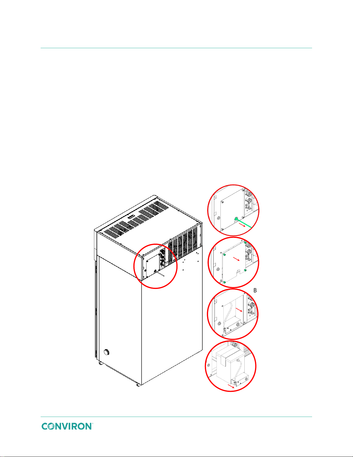
Maintenance
A
B
C
D
6.5 Maintain the Ultrasonic Humidity System (USH)
Clean the USH box every month and replace the ceramic dics every six months to maintain
optimal performance. When not in use, the USH box (located inside the machine compartment),
must be drained and cleaned. Close the water supply valve while not in use.
Set a moderate RH value in all programs to keep the USH feature operable without significantly
affecting the experiment.
To remove and clean the USH box:
1. Shut off the water supply valve to the chamber and disconnect the water line from the
USH box (Figure 6-3, Detail A).
2. Remove the USH access panel at the back of the chamber by removing the four
screws (Figure 6-3, Detail B).
3. Gently pull the USH tank out of the back of the chamber, being careful not to tip the
box (Figure 6-3, Detail C and D).
Figure 6-3 Remove the USH Box from the Chamber
July 22, 2019 | 287960-ENG | R00 49
Page 60
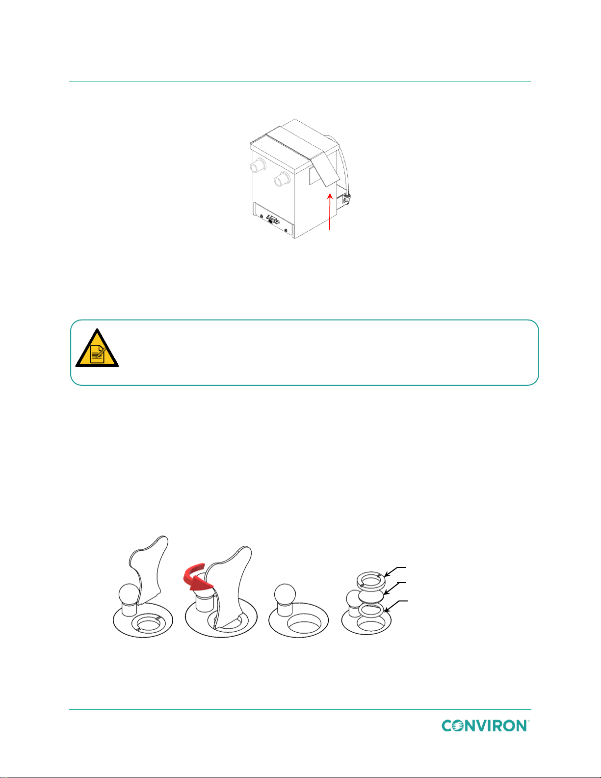
cleaner capable of removing mineral deposits, such as a diluted vinegar solution.
Disc Ring
Ceramic Disc
Silicone Seal Ring
GEN1000 Operator Manual
4. Detach the hook and loop side straps and remove the USH box lid (Figure 6-4).
Figure 6-4 Remove the USH Box Lid
5. Pour the water out of the box and wipe the interior surfaces of the USH box with a
damp cloth to remove biological residue and particulate matter.
6. Ensure there is no water residue on the ceramic discs.
Pay particular attention to the surface of the ceramic dics, which must be free of
deposits in order to function properly. Stubborn buildup may be removed with a
7. Dry the interior surfaces.
To replace the ceramic discs:
1. Contact Conviron to order the USH dics replacement kit (PN 236411).
2. Place USH puck key into the corresponding slots of the disc ring (Figure 6-5) and turn
the puck key counterclockwise to unscrew the disc ring.
3. Remove the disc ring, ceramic disc, and silicone seal.
4. Install the silicone seal ring followed by the new ceramic disc, and screw the disc ring
back into place.
50 July 22, 2019 | 287960-ENG | R00
Figure 6-5 Ceramic Disc Replacement
Page 61
Maintenance
Warning: Electrical shock hazard during maintenance or service.
maintenance or service.
The ceramic disc is very fragile; handle it with care during installation.
5. Replace the USH box lid and secure it in place with the hook and loop side straps.
This is very important to prevent water from splashing over electrical components.
6. Replace the USH box in the chamber by reversing the removal steps above.
6.6 Calibrate the Temperature and Humidity Sensor
Calibrate the temperature and humidity sensors yearly. Contact Conviron Service for more
information.
6.7 Adjust the Door
Operation of the door, at the hinge point, presents a crush hazard.
Refer to the Conviron Chambers Maintenance & Troubleshooting Manual for more information.
The door may be removed from the chamber if absolutely necessary. Contact Conviron for door
removal instructions.
6.8 Clean the Condensate Pump and Condensate Pan
Serious personal injury or death could result from contacting live electrical circuits.
Disconnect power to the pump at the rear of the chamber before performing
Clean the optional condensate pump and condensate pan regularly.
To clean the condensate pump and pan:
1. Unplug the pump and slide the condensate pump and pan out from under the front of
the chamber.
2. Clean the pan and pump with a diluted vinegar solution.
3. Reinsert the pump into the pan and slide them back under the chamber.
4. Plug the pump back into the receptacle on the rear of the chamber.
July 22, 2019 | 287960-ENG | R00 51
Page 62

GEN1000 Operator Manual
52 July 22, 2019 | 287960-ENG | R00
Page 63
7 TROUBLESHOOTING
Chamber won’t start
1. Check that the mains breaker for the chamber is ON.
2. Check the circuit breaker at the building electrical panel.
3. Ensure the program is set and running in the controller and the start/stop switch is ON.
4. Check the temperature limit settings and ensure they are outside the program range.
Still won’t start
Contact Conviron.
Chamber won’t cool
1. Check that the ambient temperature is below 35°C.
2. Ensure that the door is firmly closed.
Still won’t cool
Contact Conviron.
Chamber won’t heat
1. Check that the ambient temperature is above 20°C.
2. Ensure that the door is firmly closed.
Still won’t heat
Contact Conviron.
Chamber won’t make humidity
1. Ensure that the door is firmly closed.
2. Ensure that the fresh air ports are closed.
3. Check the water supply to the rear of the chamber.
Still no humidity
Contact Conviron.
Chamber lamp won’t light up after replacement
Possible defective ballast
Contact Conviron
Conviron Technical Support is available to all users at no charge, to either assist with
available when requesting service.
troubleshooting or to order parts, for the life of the equipment.
Have the serial number, located on the rating plate on the rear of the chamber,
7.1 Troubleshooting Steps
Even if service is close by, a few troubleshooting steps can significantly reduce the time to
diagnose and correct a fault. Make careful notes of the fault symptoms and the chamber and
ambient conditions. This could help to determine the cause of the problem.
July 22, 2019 | 287960-ENG | R00 53
Page 64

Fuse
Description
Conviron
P/N
Location
System/Component
Protected
F1
FUSE - 2.5A, 250V, MDL, TIME DELAY
233327
Main Control Panel
PLC Controller
F2
FUSE - 0.75A, 250V, ABC, FAST ACTING
79815
Main Control Panel
Central Alarm
F3
FUSE - 2.5A, 250V, MDL, TIME DELAY
233327
Main Control Panel
USH Unit
F4
FUSE - 1A, 250V, ABC, FAST ACTING
742296
Main Control Panel
Condensate Pump
F5
FUSE - 2.5A, 250V, MDL, TIME DELAY
233327
Transformer Mtg
Plate (50Hz UPS
option only)
UPS Transformer
F6
FUSE - 4A, 250V, MDL, TIME DELAY
291767
Transformer Mtg
Plate (50Hz
chamber only)
Lighting Transformer
GEN1000 Operator Manual
7.2 Fuse Schedule
54 July 22, 2019 | 287960-ENG | R00
Page 65

8 TECHNICAL SPECIFICATIONS
Specifications
GEN1000
Short Plant
(SH)
Tissue Culture
(TC)
Tall Plant
(TA)
Incubator
(IN)
Crated Weight (lbs / kg)
700 / 318
Exterior Dimensions
Height (in. / mm)
77 / 1956
Width (in. / mm)
41 / 1040
Depth (in. / mm)
32.5 / 825
Interior Dimensions
Height (in. / mm)
52.5 / 1330
Width (in. / mm)
37.5 / 953
Depth (in. / mm)
24.3 / 617
Volume (ft3 / L)
27.6 / 78
Power Requirements
The chamber will tolerate ±10% voltage fluctuation from the rated voltage on the serial plate.
A voltage stabilizer must be used if the fluctuation is greater than ±10%.
60 Hz
120Vac, 1Ph, N, PE, 60Hz, 20A
60 Hz dehumidification
120Vac, 1Ph, N, PE, 60Hz, 30A
50 Hz
230Vac, 1Ph, N, PE, 50Hz, 16A
Customer Alarm Contact
230Vac, 0.5A maximum
Environmental Requirements
Temperature
95°F (35°C) maximum
Humidity
Up to 55% RH, non-condensing
Conviron maintains a policy of continual improvement and reserves the right to change the
technical characteristics of the GEN1000 without prior notice.
July 22, 2019 | 287960-ENG | R00 55
Page 66
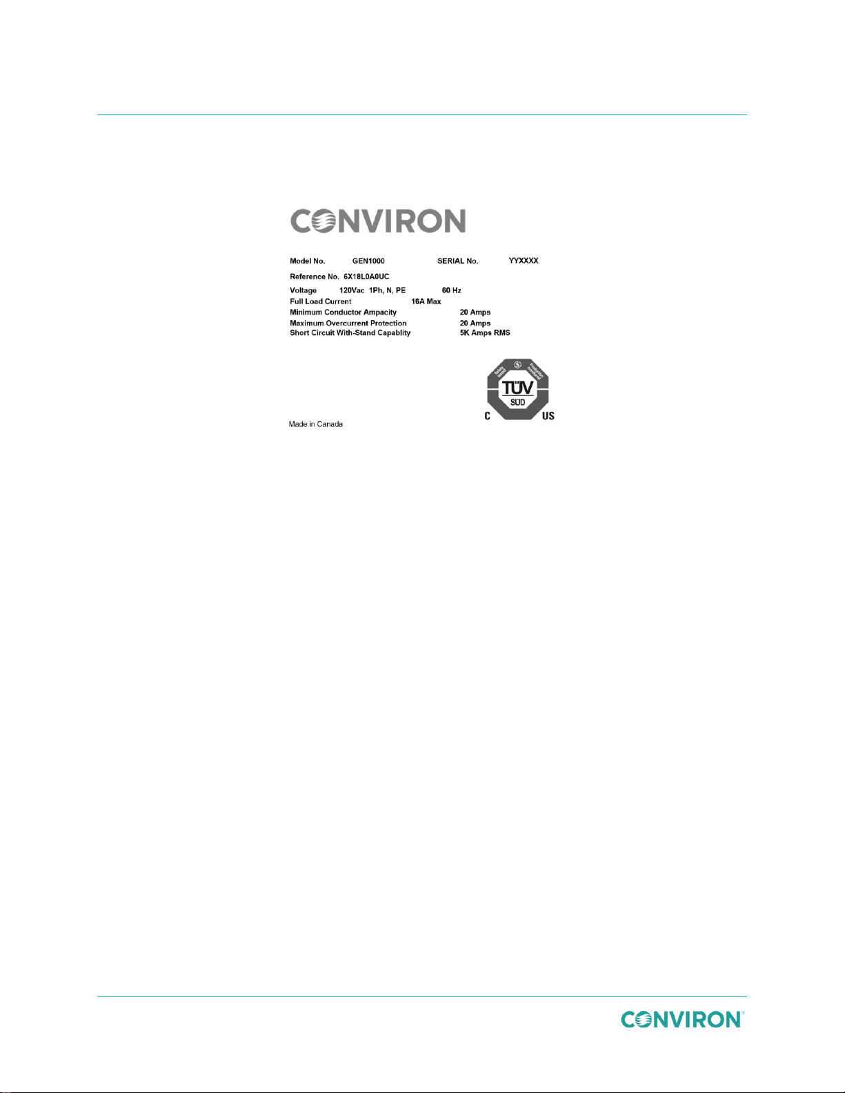
GEN1000 Operator Manual
Figure 8-1 shows an example of the GEN1000 chamber rating plate, located on the rear of the
chamber. Please have the Serial Number available when requesting service.
Figure 8-1 Sample GEN1000 Rating Plate
56 July 22, 2019 | 287960-ENG | R00
Page 67

9 ADDITIONAL INFORMATION
Term
Definition
%RH
Humidity level expressed as a percentage of the maximum relative
humidity level
Greek letter Phi – SI prefix for electrical phase
Greek letter Mu – SI prefix for micro
C
Celsius degrees
A
Amperes
AC
Air-cooled Condenser unit
AR
Arabidopsis
CFC
Chlorofluorocarbon
CM
Central Management System
COMM
Connection to LAN
EMI
Electro Magnetic Interference filter
ESD
Electrostatic Discharge
EU
European Union
Gph
Gallons per hour
GR
Ground
Hz
Hertz
ID
Inside Diameter
L/hr
Liter per hour
Lpm
Liter per minute
micromole/m2/s
Light intensity
mm
Millimeter
OD
Outside Diameter
PE
Protective Earth – mandatory ground connection
PG
Plant growth, for use with tall plants
ppm
Parts per million - used a unit of measurement for CO2 concentration
9.1 Terms & Definitions
Table 9-1 lists the terms and their definitions used throughout this manual.
Table 9-1 Terms and Definitions
July 22, 2019 | 287960-ENG | R00 57
Page 68

Term
Definition
psi
Pounds per square inch
PVC
Poly Vinyl Chloride
RoHS
Restriction of Hazardous Substances Directive
TC
Tissue Culture
UPS
Uninterruptable Power Supply
USH
Ultra Sonic Humidifier
V
Volts
WC
Water Cooled condenser unit
WEEE
Waste Electrical and Electronic Equipment
The chamber is made up of metal and plastic parts, fluids, and
electronic components. In compliance to the European Union
directive 2012/19/EC issued on July 4th, 2012, please contact
Conviron, or your Conviron distributor for proper handling and
disposal instructions.
GEN1000 Operator Manual
9.2 Disposal
58 July 22, 2019 | 287960-ENG | R00
Page 69

Page 70

Management System Certified to ISO9001
287960-ENG
©2019 Controlled Environments Limited. Conviron is a registered trademark of Controlled Environments Limited. All other trademarks are the property of their
respective owners. Information subject to change without written notice.
www.conviron.com
-R00| July 22, 2019
 Loading...