

Page 1

ALSPA MV3000e
Publication No. T1694EN Rev. 0004 (06/06)
PROFIBUS
Fieldbus Coupler MVS3007
Page 2

SAFETY INSTRUCTIONS
Care has been taken with the design of this product to ensure that it is safe.
However, in common with all products of this type, misuse can result in
injury or death. Therefore, it is very important that the instructions in this
manual and on the product are observed during transportation,
commissioning, operation, maintenance and disposal.
This technical manual should be regarded as part of the product. It should
be stored with the product and passed on to any subsequent owner or user.
Local safety laws and regulations must always be observed.
Persons working on the product must be suitably skilled and should have
been trained in that work for these products.
The product is a component designed for incorporation in installations,
apparatus and machines.
The product must not be used as a single item safety system. In
applications where maloperation of the product could cause danger,
additional means must be used to prevent danger to persons.
Product approvals and certifications will be invalidated if the product is
transported, used or stored outside its ratings or if the instructions in this
manual are not observed.
Third party approvals to safety standards UL 508C and CSA C22.2 No 14
are marked on the product.
In the European Union:
• Products within the scope of the Low Voltage Directive,
73/23/EEC as amended are CE marked.
• The product complies with the essential protection requirements
of the EMC directive 89/336/EEC as amended, when installed and
used as described in this manual. The requirements of the EMC
Directive should be established before any installation, apparatus
or machine which incorporates the product is taken into service.
• A machine should not be taken into service until the machine has
been declared in conformity with the provisions of the Machinery
(Safety) Directive, 98/37/EEC.
Page 3

ALSPA PROFIBUS Field Bus Coupler
(09/06) Technical Manual iii
Page 4

Overview ALSPA PROFIBUS Field Bus Coupler
CHANGES FROM PREVIOUS EDITION
Original edition (02/00).
Two types of PROFIBUS module described and menu 74
added. (03/03)
Minor Modifications (07/03)
Minor Modifications following Product Validation (09/04)
© - Converteam UK Ltd - 2006. Converteam, the logo and their
frameworks are trademarks and service trademark applications of
Converteam. The other names mentioned, registered or not, are the
property of their respective companies.
iv Technical Manual (09/06
Page 5
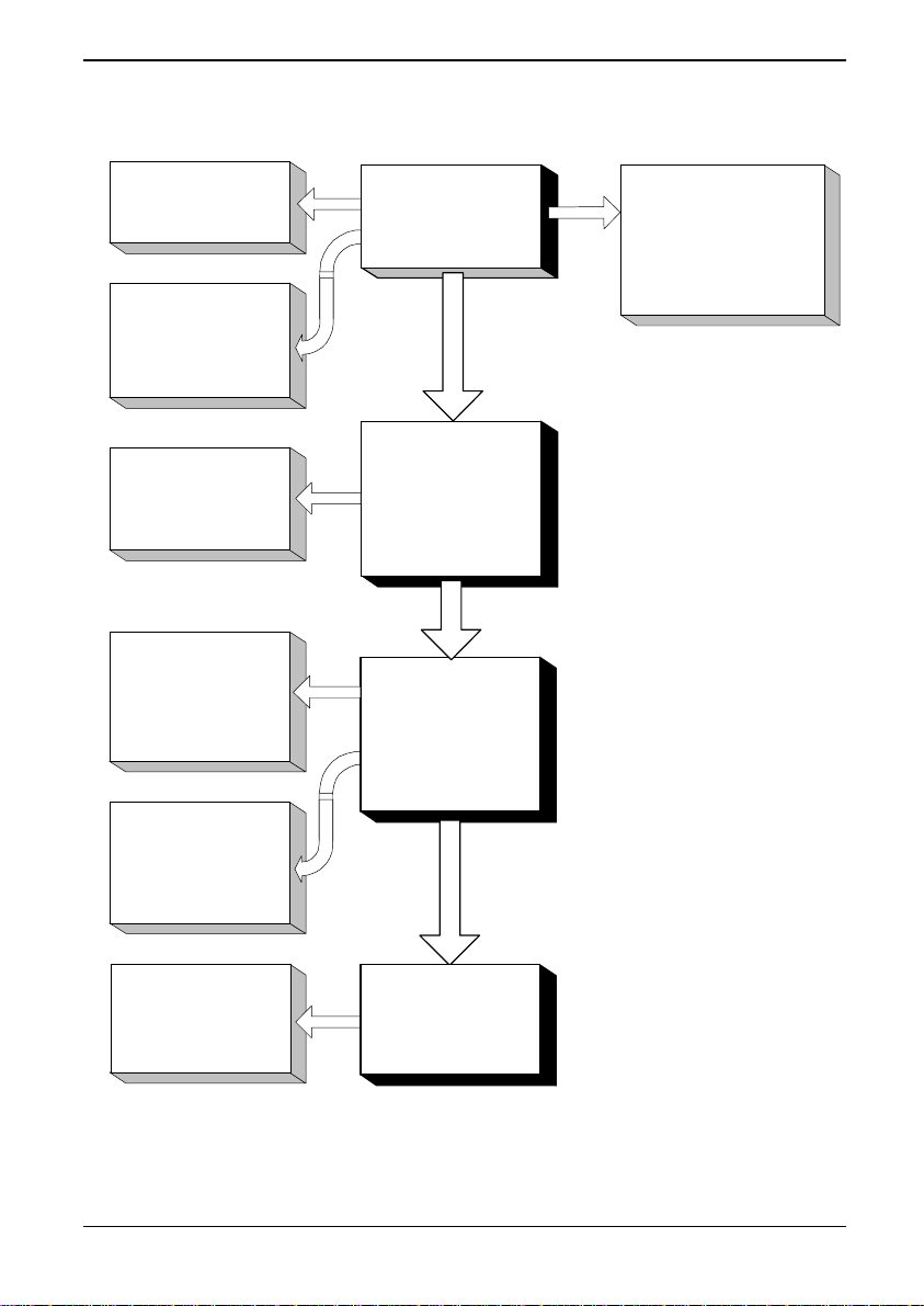
ALSPA PROFIBUS Field Bus Coupler Documentation Structure
THIS PUBLICATION
(T1694
SECTION 1
INTRODUCTION.
SECTION 2
SPECIFICATIONS.
SAFETY STANDARDS.
EMC STANDARDS.
DISPOSAL
INSTRUCTIONS.
SECTION 3
INSTALLATION AND
ELECTRICAL
CONNECTION
SECTION 5
COMMISSIONING
PROCEDURE
)
PROFIBUS
STAGES OF USE
PLANNING
INSTALLATION
COMMISSIONING
+
OPERATING
RELATED
PUBLICATIONS
BUYERS GUIDE.
MV3000 GETTING
STARTED MANUAL
T1676 OR T2002 OR
T1693.
MV3000e SOFTWARE
TECHNICAL MANUAL.
T1679
SECTION 6, 7 & 8
COMPREHENSIVE
PARAMETER
DESCRIPTIONS
SECTIONS 9 & 10
MAINTENANCE
+
DIAGNOSTIC
INFORMATION
MAINTENANCE
AND
DIAGNOSTICS
(09/06) Technical Manual v
Page 6

Overview ALSPA PROFIBUS Field Bus Coupler
OVERVIEW
Section Page
1. Introduction.......................................................................................... 1-1
A brief description of the PROFIBUS board for MV3000e drives.
2. Specifications....................................................................................... 2-1
Provides electrical, mechanical and environmental specifications for
the PROFIBUS board, also safety and EMC standards, and
disposal instructions.
3. Installation.............................................................................................3-1
Describes how to properly install the PROFIBUS board into
MicroCubicle™ drives and DELTA systems. Topics covered include
handling and storage, mechanical and electrical installation. Shows
how to configure the various PCB links and switches.
4. Commissioning.................................................................................... 4-1
Explains how to commission a PROFIBUS board using the drive
parameters described in Section 5.
5. PROFIBUS Protocol.............................................................................. 5-1
Explains the PROFIBUS protocol.
6. Parameters ............................................................................................ 6-1
Overview of drive parameters usage.
7. Menu 74 Parameters............................................................................. 7-1
Describes in detail the drive parameters used to configure and
control the PROFIBUS board.
8. Menu 75 Parameters............................................................................. 8-1
Describes in detail the drive parameters used to configure and
control the PROFIBUS board.
9. Maintenance.......................................................................................... 9-1
Describes the maintenance philosophy for the PROFIBUS board.
10. Diagnostics..........................................................................................10-1
vi Technical Manual (09/06)
Page 7

ALSPA PROFIBUS Field Bus Coupler Overview
Explains how to diagnose faults using on-board LEDs and drive
parameters.
Appendix A. Configuration example for first-time users.
Appendix B. Configuration tables.
Appendix C. Fault Return form.
Appendix D. Configuring the Master.
Glossary
INDEX
(09/06) Technical Manual vii
Page 8

Overview ALSPA PROFIBUS Field Bus Coupler
This page intentionally left blank
viii Technical Manual (09/06)
Page 9

ALSPA PROFIBUS Field Bus Coupler Table of Contents
TABLE OF CONTENTS
Section Page
1.
Introduction........................................................................................1-1
1.1 General Description 1-1
1.2 PROFIBUS Configuration 1-1
1.3 GSD File 1-1
1.4 Associated Publications 1-1
2. Specification ...................................................................................... 2-1
2.1 PROFIBUS Board Specification 2-1
2.1.1 Fieldbus 2-1
2.1.2 PROFIBUS Protocol 2-1
2.1.3 Data Refresh Rate 2-1
2.1.4 MVS3007-4001 board Data Volume 2-1
2.1.5 MVS3007-4002 board Data Volume 2-2
2.1.6 Data Consistency 2-2
2.1.7 Power Supply 2-3
2.1.8 Physical dimensions 2-3
2.1.9 Environment 2-3
2.2 Safety Standards 2-3
2.3 EMC Standards 2-3
2.4 Disposal Instructions 2-4
3. Installation..........................................................................................3-1
3.1 PCB Handling Information 3-1
3.1.1 Receipt of Equipment on Site 3-1
3.1.2 Storage 3-1
3.2 Configuration Details for Drive Modules 3-1
3.3 MVS3007-4001 PROFIBUS Board Configuration 3-2
3.3.1 Location of Switches 3-3
3.3.2 Switch Settings 3-4
3.4 MVS3007-4002 PROFIBUS Board Configuration 3-4
3.4.1 Switch Settings 3-5
3.4.2 Location of Switch S2 3-7
3.5 Installation Procedure for ALSPA MV3000e MicroCubicle™ Drives 3-8
3.6 Installation Procedure for ALSPA MV DELTA & MV-LCD Systems 3-12
3.7 Connections 3-14
3.7.1 External Wiring 3-14
3.7.2 PROFIBUS Connectors 3-14
3.7.3 9 Way DIN Connections 3-15
3.7.4 PROFIBUS Cable 3-16
3.7.5 PROFIBUS Earthing 3-16
3.7.6 Bus cable termination 3-17
4. Commissioning.................................................................................. 4-1
4.1 Mechanical Checks 4-1
(09/06) Technical Manual ix
Page 10

Table of Contents ALSPA PROFIBUS Field Bus Coupler
4.2 PROFIBUS Configuration 4-1
5. PROFIBUS-DP Protocol.................................................................... 5-1
5.1 Introduction 5-1
5.2 PROFIBUS Protocol 5-1
5.2.1 Process Data and PROFIDRIVE 5-1
5.2.2 Parameter process data object types 5-1
5.3 Configuring a PROFIBUS-DP Master 5-3
6. Menu Parameters............................................................................... 6-1
6.1 Introduction 6-1
6.2 Parameter Attributes 6-1
6.3 Access Authority 6-2
6.4 List Parameters 6-2
7. Menu 74 Parameters.......................................................................... 7-1
7.1 Introduction 7-1
7.2 PROFIBUS Menu 74 7-1
7.3 Basic Settings Explanation 7-1
7.4 Menu 74 Description 7-2
7.4.1 Expansion bus device P74.00 7-2
7.4.2 Protocol P74.01 7-2
7.4.3 Node Address P74.02 7-2
7.4.4 PPO Type P74.03 7-2
7.4.5 Auto Configure P74.04 7-3
7.4.6 Configure Link P74.05 7-3
7.4.7 Use FBC Data P74.06 7-4
7.4.8 Source Loss Action P74.07 7-4
7.4.9 Freeze/Fallback Action P74.08 7-4
7.4.10 Communications Status P74.09 7-5
7.4.11 Data Errors P74.10 to P74.13 7-5
7.4.12 Reference holders P74.20 to P74.38 7-6
7.4.13 Control Words P74.40 & P74.42 7-8
7.4.14 Received Data Parameters P74.50 to P74.69 7-8
7.4.15 Transmitted Data, P74.70 to P74.89 7-9
7.4.16 FBC 1 Config Menu 74 7-11
7.5 Scale Menu 60 Description 7-14
7.5.1 Scaling Parameter Menu 60 7-15
7.6 Data Spy Parameters P89.00 to P89.10 7-15
8. Menu 75 Parameters.......................................................................... 8-1
8.1 Introduction 8-1
8.2 PROFIBUS Menu 8-1
8.3 Data Update Rate 8-1
8.4 Basic Settings Explanation 8-1
8.5 Menu 75 Description 8-2
8.5.1 Expansion bus device P75.00 8-2
8.5.2 Node Address P75.02 8-2
x Technical Manual (09/06)
Page 11

ALSPA PROFIBUS Field Bus Coupler Table of Contents
8.5.3 Protocol P75.03 8-2
8.5.4 Run On Power Up P75.04 8-3
8.5.5 Configure Link P75.05 8-3
8.5.6 Source Loss Action P75.06 8-3
8.5.7 Freeze/Fallback Action P75.07 8-4
8.5.8 Control Words P75.08 & P75.10 8-4
8.5.9 Received Data Parameters P75.22 to P75.27 8-5
8.5.10 References P75.12 to P75.21 8-5
8.5.11 Transmitted Data, P75.30 to P75.35 8-6
8.5.12 Reference Scaling and Masking, P75.28 to P75.29 8-8
8.5.13 Data Spy Parameters P75.36 to P75.41 8-9
8.5.14 Data Errors P75.42 to P75.45 8-9
8.5.15 Communications Status P75.46 8-10
8.6 Fieldbus Configuration Menu 8-11
9. Maintenance....................................................................................... 9-1
10. Diagnostics ...................................................................................... 10-1
10.1 Menu 74 Diagnostics 10-1
10.1.1 Faults 10-1
10.1.2 PROFIBUS Warning Fault Code 10-1
10.1.3 PROFIBUS Trip Fault Code 10-1
10.2 Menu 75 Diagnostics 10-2
10.2.1 Faults 10-2
10.2.2 PROFIBUS Warning Fault Code 10-2
10.2.3 PROFIBUS Trip Fault Code 10-2
10.3 MVS3007-4001 and MVS3007-4002 Fieldbus Coupler Indicator LEDs 10-3
10.4 Spares and Re-order Information 10-3
Appendix A. Configuration Example........................................................1
A.1 Check the PROFIBUS Hardware 1
A.2 Decide what information needs to be transferred. 1
A.3 Configure the PROFIBUS Link 2
A.4 Adding Drive Parameters 2
A.5 Simple Parameters 2
A.6 Reference Parameters 3
A.7 Control Bits 5
A.8 Status Word 6
A.9 Data for Master Device Configuration 7
A.10 Using PROFIBUS Data Spy 7
A.11 Check For Data Errors 8
A.12 Fallback Values 8
A.13 Warning on Loss of PROFIBUS Link 9
Appendix B. Configuration Tables...........................................................1
Appendix C. Fault Return Form................................................................1
(09/06) Technical Manual xi
Page 12

Table of Contents ALSPA PROFIBUS Field Bus Coupler
Appendix D. Configuring the Master........................................................1
D.1 ALSPA C80-35 PLC using ALSPA P80 1
D.1.1 Type 2 PPO packets 1
D.1.2 Type 4 PPO packets 1
D.2 Example Disk 1
Glossary
INDEX
xii Technical Manual (09/06)
Page 13

ALSPA PROFIBUS Field Bus Coupler 1. Introduction
1. Introduction
1.1 General Description
The ALSPA MV3000e PROFIBUS Fieldbus Coupler may be
retrofitted to the whole range of ALSPA MV3000e drives and allows
the drive to be connected to a PROFIBUS-DP network.
This manual describes the two types of PROFIBUS Fieldbus
Coupler that may be fitted in an ALSPA MV3000e AC drive
- MVS3007-4001 supplied up to December 2002 and
- MVS3007-4002 supplied after December 2002.
1.2 PROFIBUS Configuration
The PROFIBUS board is used as a slave device on a PROFIBUS
link.
The board is parameterised and controlled using the same
parameter interface as the rest of the drive. The board may also be
configured over the drive’s serial links, but it is not possible to
configure the board over the PROFIBUS link itself.
1.3 GSD File
The GSD file is used to provide a profile of the slave device to the
master device on the bus. The files for both ALSPA PROFIBUS
Fieldbus Couplers are provided on a diskette supplied with the
PROFIBUS board.
1.4 Associated Publications
T1676 – ALSPA MV3000e Getting Started Manual
T1679 – ALSPA MV3000e Software Technical Manual
T1689 – ALSPA MV DELTA (Air Cooled) Technical Manual
T1693 – ALSPA MV DELTA (Liquid Cooled) Technical Manual
(09/06) Technical Manual Page 1-1
Page 14

1. Introduction ALSPA PROFIBUS Field Bus Coupler
This page intentionally left blank
Page 1-2 Technical Manual (09/06)
Page 15

ALSPA PROFIBUS Field Bus Coupler 2. Specification
2. Specification
2.1 PROFIBUS Board Specification
2.1.1 Fieldbus
Capable of communication rates from 9600 bit/s to 12Mbit/s (1.5M
bits/s for MVS3007-4001 PROFIBUS board).
Automatic Baud rate
• 9,600 bits/s
• 19,200 bits/s
• 93,750 bits/s
• 187,500 bits/s
• 500K bits/s
• 1.5M bits/s
• 3M bits/s (MVS3007-4002 PROFIBUS board only)
• 6M bits/s (MVS3007-4002 PROFIBUS board only)
• 12M bits/s (MVS3007-4002 PROFIBUS board only)
2.1.2 PROFIBUS Protocol
1
selection from the following list:
Implements the PROFIBUS-DP Fieldbus protocol according to DIN
19245.
2.1.3 Data Refresh Rate
Data is exchanged between the PROFIBUS Fieldbus module and
the drive's parameters every 10ms.
2.1.4 MVS3007-4001 board Data Volume
Cyclic Channel Receive:
• 1 control word (16 bit), and
• 5 reference demands (16 bit),
or,
• 2 control words (16 bit), and
• 4 reference demands. (16 bit).
1
If at any time the baud rate is changed in the PROFIBUS-DP master then it is
necessary to power cycle the drive for the change to be recognised by this module.
(09/06) Technical Manual Page 2-1
Page 16
2. Specification ALSPA PROFIBUS Field Bus Coupler
Cyclic Channel Transmit:
• 1 status word (16 bit), and
• 5 monitor values (16 bit).
2.1.5 MVS3007-4002 board Data Volume
Cyclic Channel Receive:
• 1 control word (16 bit), and
• 1, 5 or 9 reference demands (16 bit),
or,
• 2 control words (16 bit), and
• 0, 4 or 8 reference demands. (16 bit).
Cyclic Channel Transmit:
• 1 status word (16 bit), and
• 1, 5 or 9 monitor values (16 bit).
2.1.6 Data Consistency
CAUTION
When using the PROFIBUS interface to transfer values that
span more than one 16-bit word (e.g. a 32-bit value) the
interface does not guarantee that all members of the data set
will be sent at the same time. The user must therefore ensure
that the received value is valid.
This is best explained by an example:
The position Feedback is contained in two parameters, P38.02 and
P38.03. If the drive is configured to transmit these parameters to the
PROFIBUS network and the value is changing, the following
sequence of values could be transmitted on consecutive
PROFIBUS transmissions:
Page 2-2 Technical Manual (09/06)
Page 17

ALSPA PROFIBUS Field Bus Coupler 2. Specification
PROFIBUS
Transmissio
n Number
1 00009999 0000 9999 00009999
2 00010000 0001 0000 000000002
3 00010000 0001 0000 00010000
Actual
Value
2.1.7 Power Supply
Power is supplied by an internal 5V supply, with a nominal current
consumption of 315mA
2.1.8 Physical dimensions
The PROFIBUS PCB measures 160mm by 100mm and weighs
approximately 165g
2.1.9 Environment
Storage - Altitude (max.) 3000 m
Temperature range -25°C to +55°C
Relative Humidity 5% to 95% non-condensing
Transport - Altitude (max.) 3000 m
Relative Humidity ≤ 95% non-condensing
Vibration, drop IEC 60721-3-2 Class 2M1
Operating - Altitude (max.) 3000 m
Temperature range 0°C to +50°C
Relative Humidity 5% - 95% non-condensing
Vibration IEC 60721-3-3 Class 3M1 & EN50178
2.2 Safety Standards
P38.03 P38. 02 Value Received
over PROFIBUS
pr EN50178 Electronic equipment for use in power installations.
2.3 EMC Standards
EN61800-3 / IEC61800-3.
2
I.e. the value of P38.03 from transmission 1 and P38.02 from transmission 2.
(09/06) Technical Manual Page 2-3
Page 18

2. Specification ALSPA PROFIBUS Field Bus Coupler
2.4 Disposal Instructions
This equipment or any part of the equipment should be disposed of
in accordance with the laws of the country of use.
Page 2-4 Technical Manual (09/06)
Page 19

ALSPA PROFIBUS Field Bus Coupler 3. Installation
3. Installation
3.1 PCB Handling Information
An earthed anti-static wristband must be worn when handling the
PROFIBUS board.
3.1.1 Receipt of Equipment on Site
Where the PROFIBUS board is shipped separate to the general
drive assembly, the equipment should be carefully unpacked and
inspected for any signs of damage. Check the complete
consignment against the packing slip for any loss in transit. If any
damage or loss has occurred, contact your local supplier
immediately giving the following details:
- A list of damaged or missing items.
- A description of the damage.
- The order number or packing slip details.
3.1.2 Storage
If the equipment delivered to site is not to be installed immediately:
- Re-pack it in its original packing material.
- Store it in a clean dry atmosphere, preferably at room
temperature. See section
3.2
(09/06) Technical Manual Page 3-1
Configuration Details for Drive Modules
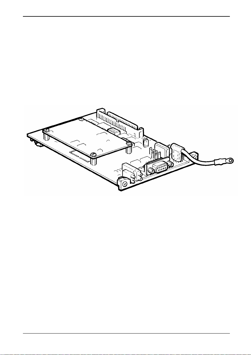
There are two types of PROFIBUS board. The MVS3007-4001
board is identifiable by the daughter board mounted on pillars and
the presence of the 8 way Dual in Line (DiL) switch, S3. See
3-1 MVS3007-4001 PROFIBUS Board and Figure 3-2 MVS30074001 PROFIBUS Layout. The MVS3007-4002 board has neither
the daughter board nor switch S3 fitted.
When fitted in a drive, the MVS3007-4001 and MVS3007-4002
PROFIBUS boards are differentiated by the position of the 9 pin D
connector. The connector is in the middle of the MVS3007-4001
board, whereas on the MVS3007-4002 board the connector is close
to the LED indicators.
2.1.9.
Figure
Page 20
3. Installation ALSPA PROFIBUS Field Bus Coupler
It is important that the switches and links on the PROFIBUS board
be set before installation into the drive, as changing these will
require removal of the module.
3.3 MVS3007-4001 PROFIBUS Board Configuration
The switch settings and link connections that may be configured are
shown in Tables 1 and 2. The default settings and connections are
recommended for MV3000e applications and are indicated by
asterisks
*.
Figure 3-1 MVS3007-4001 PROFIBUS Board
Page 3-2 Technical Manual (09/06)
Page 21
ALSPA PROFIBUS Field Bus Coupler 3. Installation
3.3.1 Location of Switches
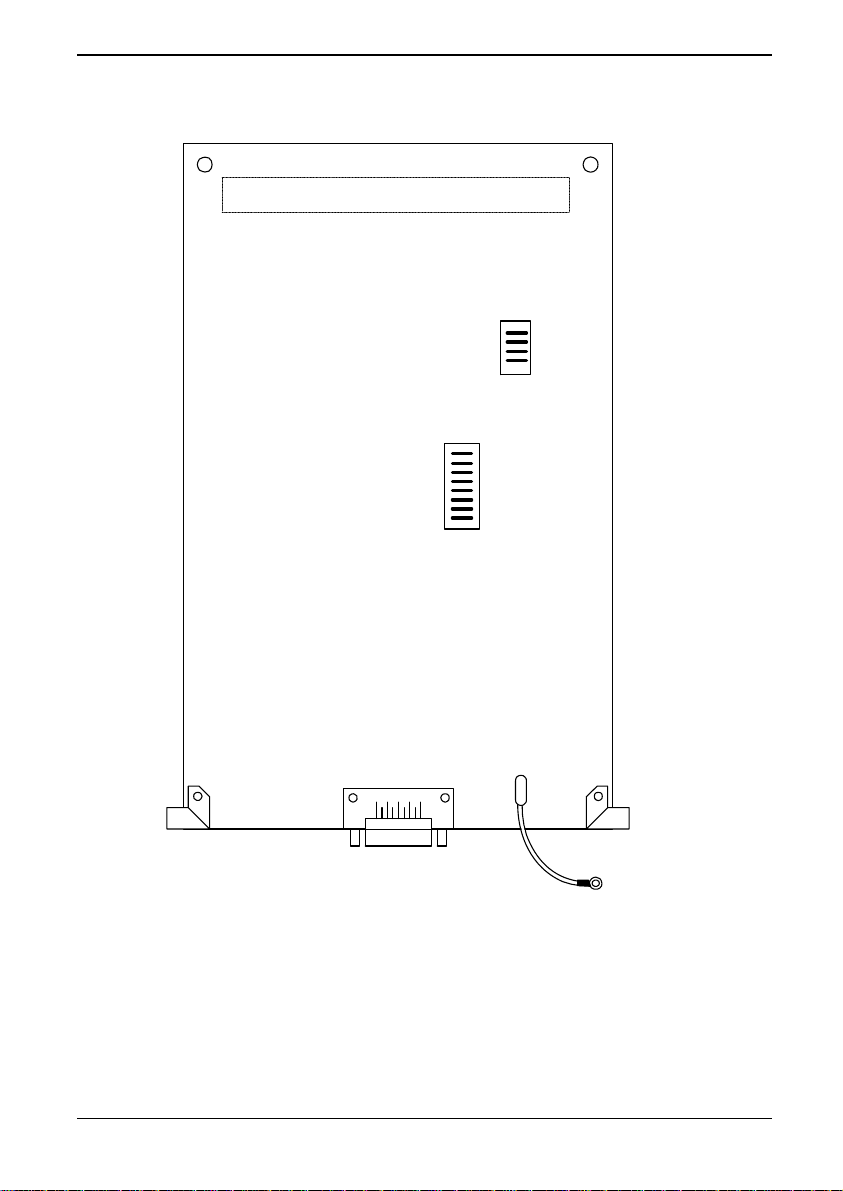
96-way connector
X1
S2
S3
X2
PE1
Figure 3-2 MVS3007-4001 PROFIBUS Layout
(09/06) Technical Manual Page 3-3
Page 22
3. Installation ALSPA PROFIBUS Field Bus Coupler
3.3.2 Switch Settings
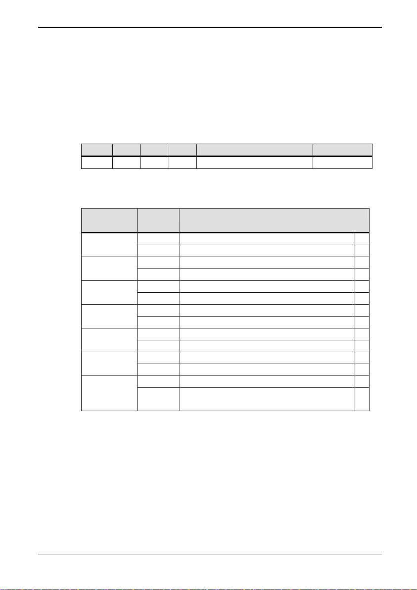
The MVS3007-4001 PROFIBUS board has two Dual-in-Line
switches, S2 and S3, which must be configured as per Tables 3-1
and 3-2.
The switches are located as shown inside the front cover.
Table 3-1 Switch S2 meanings
S2.1 S2.2 S2.3 S2.4 Dual Port RAM Address Units
On On Off Off F000 – F3FF (Hex) MV3000e *
Table 3-2 Switch S3 meanings
Switch (S)
State Meaning
Jumper (X)
On Not used S3-1
Off PROFIBUS DP mode *
On MV3000e mode * S3-2
Off
On Not used, must be Off S3-3
Off Not used, must be Off *
On Use PPO type 2 (10 words long) S3-4
Off Use PPO type 4 (6 words long) *
On Zero references on loss of Master S3-5
Off Freeze references on loss of Master *
On Not used. S3-6 to
S3-8
Off Not used. *
1-2 Watchdog monitors drive activity *
X23
2-3 Watchdog monitors PROFIBUS
module activity
* Default settings/connections
3.4 MVS3007-4002 PROFIBUS Board Configuration
The switch settings and link connections that may be configured is
shown in
recommended for MV3000e applications and are indicated by
ast
Table 3-3. The default settings and connections are
erisks
*.
Page 3-4 Technical Manual (09/06)
Page 23
ALSPA PROFIBUS Field Bus Coupler 3. Installation
The MVS3007-4002 board is supplied with a terminator PCB that
must be removed to gain access to switch S2. Replace the
terminator PCB after adjusting switch S2.
3.4.1 Switch Settings
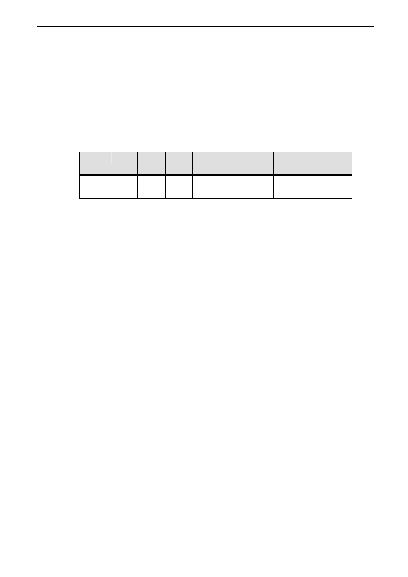
The MVS3007-4002 PROFIBUS board has one Dual-in-Line switch,
S2, which must be configured as per
Table 3-3.
Table 3-3 Switch S2 meanings
S2.1 S2.2 S2.3 S2.4 Dual Port RAM
Menu Activated
Address (Hex)
On* On* Off Off F000 – F3FF Menu 75
Off On Off Off F400 – F7FF Menu 74
* Default settings/connections
(09/06) Technical Manual Page 3-5
Page 24

3. Installation ALSPA PROFIBUS Field Bus Coupler
Figure 3-3 MVS3007-4002 PROFIBUS Board
Page 3-6 Technical Manual (09/06)
Page 25
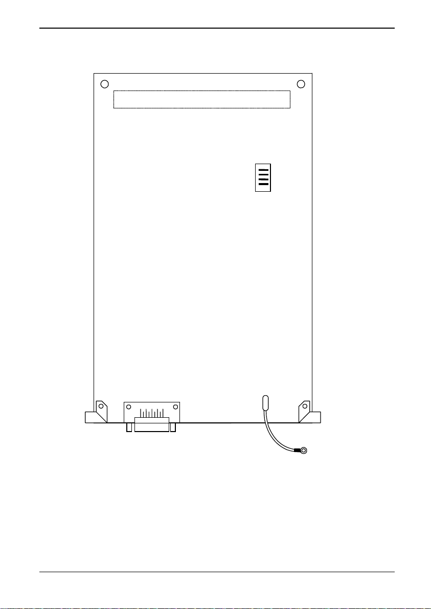
ALSPA PROFIBUS Field Bus Coupler 3. Installation
3.4.2 Location of Switch S2
96-way connector
X1
S2
X210
PE1
Figure 3-4 MVS3007-4002 PROFIBUS Layout
(09/06) Technical Manual Page 3-7
Page 26
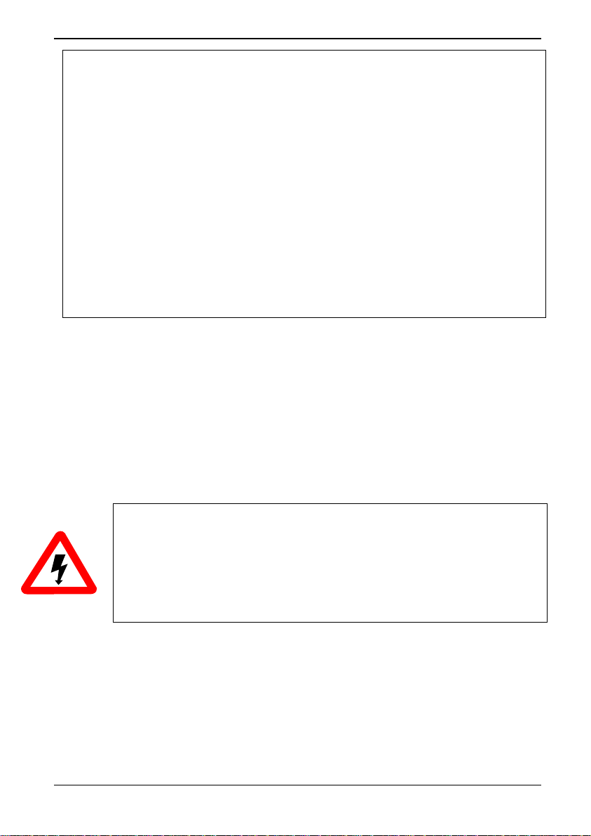
3. Installation ALSPA PROFIBUS Field Bus Coupler
Figure 3-5 Close Up of S2 with terminator removed.
3.5 Installation Procedure for ALSPA MV3000e MicroCubicle™
Drives
1. Switch off the mains supply to the drive and ensure that the drive
is fully isolated.
WARNINGS
• This equipment may be connected to more than one live
circuit. Disconnect all supplies before working on the
equipment.
• Wait at least 5 minutes after isolating supplies and check
that voltage between DC+ and DC- has reduced to a safe
level before working on this equipment.
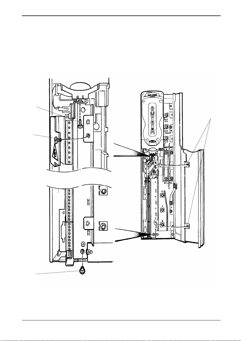
2. Refer to Figure 3-6 and fully open the drive doors as follows:
i. Open the left hand yellow plastic door beneath the Keypad
harbour by carefully pulling the bottom of the door and/or
the depression at the top.
ii. Open the right hand door by releasing the two screws (C).
Page 3-8 Technical Manual (09/06)
Page 27
ALSPA PROFIBUS Field Bus Coupler 3. Installation
B A
3. Release the screw (A) securing the plastic terminal shroud.
Remove and retain the two screws and washers (B) securing the
control module to the drive chassis.
Figure 3-6 Drive module – access and release the control board
B
C
(09/06) Technical Manual Page 3-9
Page 28
3. Installation ALSPA PROFIBUS Field Bus Coupler
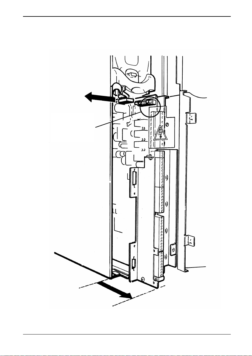
4. Slide the control board completely forward out of the drive, disconnecting
any ribbon connectors located at the top of the board, (see Figure 3-7),
and noting their positions for ease of re-connecting.
Disconnect any
ribbon connector
in this area.
Figure 3-7 Drive module – removing the control board
Page 3-10 Technical Manual (09/06)
Page 29
ALSPA PROFIBUS Field Bus Coupler 3. Installation
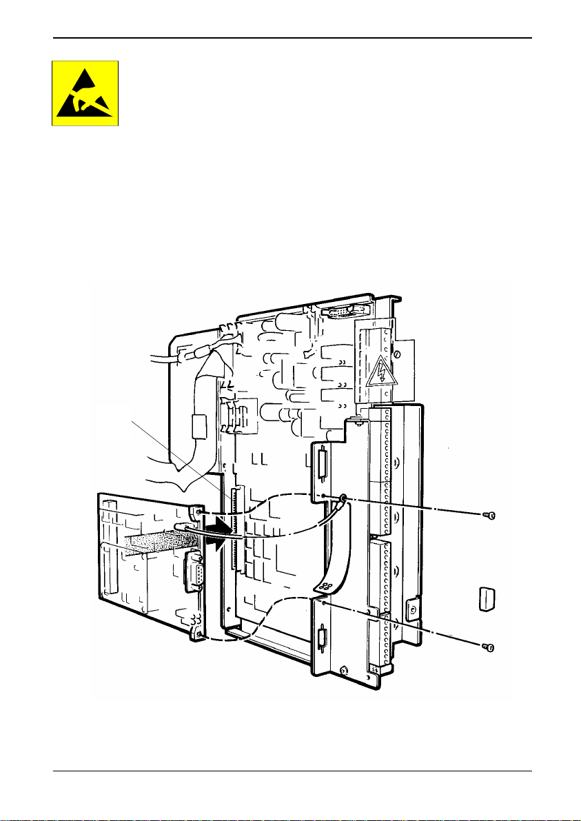
CAUTION
This equipment contains solid state devices which may be
affected by electrostatic discharge. Observe static handling
precautions.
5. Fit the PROFIBUS board into the 96-way socket (B) at the back of
the control board, as shown in
front plate with the two screws provided, locating the ring crimp of
the free yellow/green earth lead (A) under one of the screws.
6.
Attach the label (C) if supplied, and fit dust covers (D) to any
PROFIBUS connector that will be exposed for a lengthy period,
Figure 3-8.
see
B
Figure 3-8. Secure it to the steel
Figure 3-8 Drive module – fitting the PROFIBUS board
(09/06) Technical Manual Page 3-11
Page 30
3. Installation ALSPA PROFIBUS Field Bus Coupler
7. Slide the control module back into the drive and re-connect the
ribbon connectors that were disconnected at step 4.
8. Secure the control drive to the drive chassis using the two screws
and washers removed at step 3. Close the plastic terminal shroud
and secure with the retained screw, then close and secure the
drive doors.
3.6 Installation Procedure for ALSPA MV DELTA & MV-LCD
Systems
1. Switch off the mains supply to the drive and ensure that the drive
is fully isolated.
WARNINGS
• This equipment may be connected to more than one live circuit.
Disconnect all supplies before working on the equipment.
• Wait at least 5 minutes after isolating supplies and check that
voltage between DC+ and DC- has reduced to a safe level before
working on this equipment.
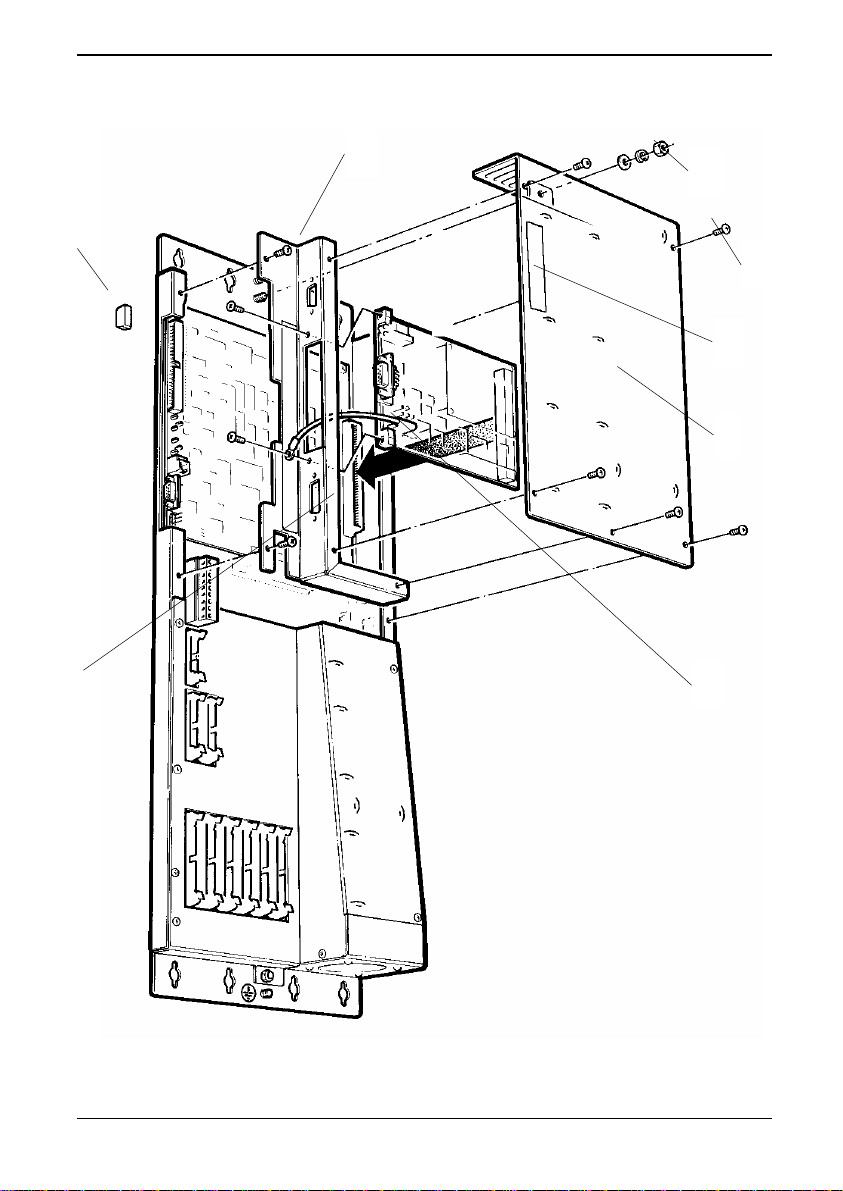
2. Referring to Figure 3-9, remove the five M4 screws (E), and the
M5 nut and washers (D) (next to the M5 earth stud), which
secure the steel cover plate (G) covering the control board.
Note:
3. Remove the two M4 screws securing the steel front panel (C)
If this is difficult due to restricted access, remove the
MV3000e controller as described in T1689 (air cooled)
or T1693 (liquid cooled).
to the chassis.
CAUTION
This equipment contains solid-state devices that may be
affected by electrostatic discharge. Observe static handling
precautions.
4. Fit the PROFIBUS board to the front panel with the two screws
provided, locating the ring crimp of the free yellow/green earth
lead (H) under the nearest of the screws.
Page 3-12 Technical Manual (09/06)
Page 31
ALSPA PROFIBUS Field Bus Coupler 3. Installation
C
D
B
E
F
G
A
H
Figure 3-9 DELTA system – fitting the PROFIBUS board
(09/06) Technical Manual Page 3-13
Page 32
3. Installation ALSPA PROFIBUS Field Bus Coupler
5. Locate the 96-way connector on the PROFIBUS board into the
socket (A) at the back of the control board, as shown in
Figure 3-9. Secure the front panel to the chassis using the two
M4 screws removed at step 3.
6.
Attach the label (F) if supplied, and fit dust covers (B) to any
PROFIBUS connector that will be exposed for a lengthy period,
Figure 3-9.
see
Re-fit the cover plate over the control board, using the five
7.
screws and the M5 nut and washers removed at step 2.
3.7 Connections
CAUTION
This equipment contains solid-state devices that may be
affected by electrostatic discharge. Observe static handling
precautions.
Connections to the PROFIBUS board must use 9 way D-type
PROFIBUS connectors fitted with 440UNC screwjacks.
3.7.1 External Wiring
It is important to strain relieve the PROFIBUS cable before it is
connected to the drive. Strain relief helps to prevent damage to the
PROFIBUS connection or the cable being unexpectedly unplugged.
Electrical noise and electromagnetic interference can be introduced
into a microelectronics system via the cables and wires connected
to it. To avoid this, wiring which could carry noise, that is ‘dirty’
cables, should be kept away from cables that are to be kept free
from electrical noise or ‘clean’. Wiring that falls into the same group
can be run together, while wiring from different groups should be
kept apart, though paths may cross at right angles. All connections
to the PROFIBUS board are considered to be clean.
3.7.2 PROFIBUS Connectors
The PROFIBUS board contains 1 external connection, a 9 way Dtype female connector that is used to connect to the PROFIBUS
network cable.
Page 3-14 Technical Manual (09/06)
Page 33
ALSPA PROFIBUS Field Bus Coupler 3. Installation
Connectors conforming to the PROFIBUS standard are
recommended, e.g. DIN 41652.
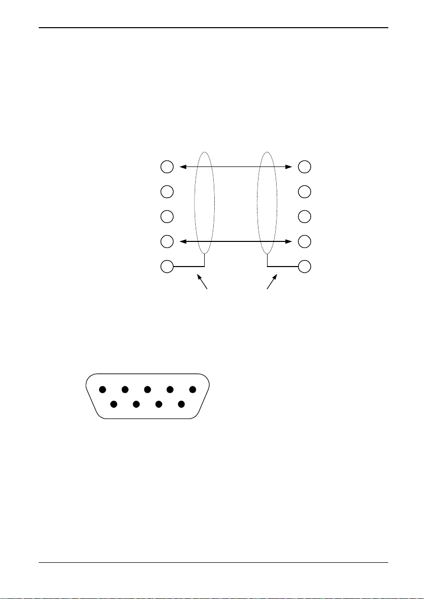
Note that the making of a ‘T’ in the PROFIBUS network is not
allowed, the cable must always be daisy-chained, as shown in
Figure 3-10 below.
Station 1 Station 2
DATA +
+5 V Isolated
GND Isolated
DATA -
3
6
5
8
1
Figure 3-10 Interconnecting two PROFIBUS stations
3.7.3 9 Way DIN Connections
12345
6789
Figure 3-11 Pin-out of the PROFIBUS 9 pin D-type connector
Protective earth (ground)
View looking into the
mating face of the
connector.
3
6
5
8
1
The PROFIBUS connections are as follows:
Pin 1 = Protective earth (PE) or screen.
Pin 3 = DATA+
Pin 5 = GND (isolated)
Pin 6 = +5V (isolated)
(09/06) Technical Manual Page 3-15
Page 34
3. Installation ALSPA PROFIBUS Field Bus Coupler
Pin 8 = DATA–
3.7.4 PROFIBUS Cable
Twisted pair shielded cable equivalent to Belden 8227 is
recommended.
- Two core cable, screened and twisted.
- Resistance 100 to 120 ohm at f > 100 kHz.
- Capacitance < 60 pF per meter.
2
- Minimum cross section of 0.22 mm
(24 AWG).
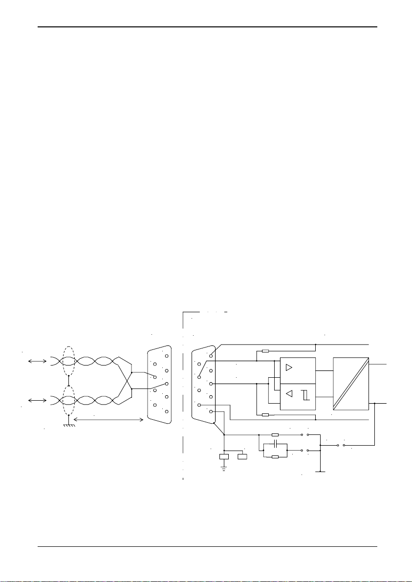
3.7.5 PROFIBUS Earthing
To ensure an EMC compliant installation, the network cable screens
must be continuous.
On the PROFIBUS board, the protective earth (PE) is connected
through the flat connector PE2 to the cable shield. The MV3000e
enclosure must be connected to PE with the largest practicable
cable cross-section.
PROFIBUS board
TXD/RXD
RXD/TXD
Drive Mounting Plate
50 cm or less
Plug
5
9
4
8
3
7
2
6
1
Socket
9
8
7
6
5
4
3
2
1
DC 0V ISO
DC+5V ISO
PE2PE1
LS3
DC 0V isolated
DC 5 V isolated
LS2LS1
LS5
LS4
DC 0V isolated
Figure 3-12 Protective earth arrangement
Page 3-16 Technical Manual (09/06)
LS6
0V electronics
Page 35
ALSPA PROFIBUS Field Bus Coupler 3. Installation
Note: Use a metal P-clip to bond the braid to the Drive mounting
plate. The clip should be no more than 50 cm from the
connector.
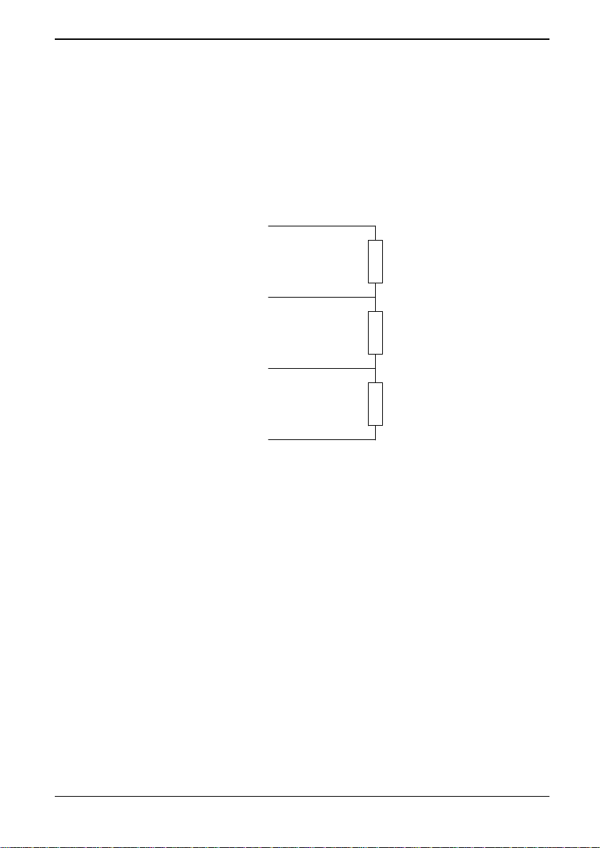
3.7.6 Bus cable termination
It is necessary to terminate both ends of the network, typically as
shown in Figure 3-13. Power must be applied to both terminations
to ensure correct operation.
+5 V Isolated
390 ohm
DATA +
220 ohm
DATA -
390 ohm
GND Isolated
Figure 3-13 PROFIBUS link termination
(09/06) Technical Manual Page 3-17
Page 36

3. Installation ALSPA PROFIBUS Field Bus Coupler
This page intentionally left blank
Page 3-18 Technical Manual (09/06)
Page 37

ALSPA PROFIBUS Field Bus Coupler 4. Commissioning
4. Commissioning
4.1 Mechanical Checks
Check that:
- The PROFIBUS board has been installed into the drive in
accordance with the instructions given in Section 3.
Refer to the Getting Started Manual T1676 for relevant
checks of the Drive equipment.
4.2 PROFIBUS Configuration
The ALSPA MV3000e drives are configured, controlled and
monitored by reading and writing drive parameter values. This
principle extends to the PROFIBUS board when it is fitted. Drive
parameters are accessed either:
- Using Serial Link communications, (not including the
PROFIBUS Fieldbus).
- Using the Drive Data Manager™ (Keypad) or the PC
programming package ALSPA Drive Coach.
Use of the Keypad and serial links for the drive is explained in the
MV3000e Technical Manuals.
Sections
PROFIBUS board, using the drive parameters. To aid configuration
of the PROFIBUS board, a worked example is provided in Appendix
A.
7 and 8 describe how to configure and control the
(09/06) Technical Manual Page 4-1
Page 38

4. Commissioning ALSPA PROFIBUS Field Bus Coupler
This page intentionally left blank
Page 4-2 Technical Manual (09/06)
Page 39
ALSPA PROFIBUS Field Bus Coupler 5. PROFIBUS-DP Protocol
5. PROFIBUS-DP Protocol
5.1 Introduction
This section gives a brief overview of the PROFIBUS protocol when
applied to Variable Speed Drives.
5.2 PROFIBUS Protocol
The PROFIBUS board implements the PROFIBUS-DP protocol.
5.2.1 Process Data and PROFIDRIVE
CAUTION
When using the PROFIBUS interface to transfer values that
span more than one 16-bit word (e.g. a 32-bit value) the
interface does not guarantee that all members of the data set
will be sent at the same time. The user must therefore ensure
that the received value is valid.
Process data is transferred using the PROFIBUS process data
object (PPOs) packets. The PROFIBUS Profile for Variable Speed
Drives (PROFIDRIVE) contains the drive specific definition of these
PPOs. Depending on the direction of the data transfer, the PPOs
contain either control words and set points or status words and
actual values. The PPOs are sent on a regular cyclic basis at a rate
determined by the Baud rate and number of PROFIBUS devices on
the network.
2.1.6.
5.2.2
Refer to the example in
Parameter process data object types
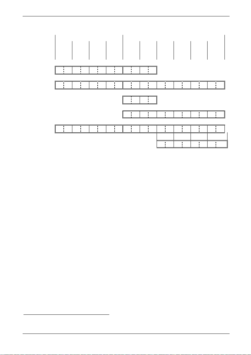
Within PROFIDRIVE, there are five different types of PPO. Each
type of PPO is defined to contain all or some of the PPO fields.
The MVS3007-4001 PROFIBUS Fieldbus coupler only supports
either the PPO type 2 or the PPO type 4 packet, selected by DIP
switch S3-4, (see Section
shorter of the two and only contains the last 12 octets of the type 4
PPO. These are shown in
(09/06) Technical Manual Page 5-1
3.3.2). The PPO type 4 packet is the
Figure 5-1.
Page 40
5. PROFIBUS-DP Protocol ALSPA PROFIBUS Field Bus Coupler
The fields are defined as 16 bit words. Two octets form one word.
PKW PZD
PZD3
STW
ZSW
PZD2
HSW
HIW
PZD4 PZD5 PZD6
PKE IND PWE PWE PZD1
PPO Type 1: Length 12 octets.
PPO Type 2: Length 20 octets.
PPO Type 3: Length 4 octets.
PPO Type 4: Length 12 octets.
PPO Type 5: Length 28 octets.
PPO Type 5 continued …. PZ D7
Figure 5-1 - Parameter process data objects
PZD8 PZD9 PZD10
The abbreviations derive from the PROFIBUS definition of each and
are kept the same to correspond to the PROFIDRIVE terminology:
PKW = Parameter ID/value
PKE = Parameter ID
IND = Sub-index
PWE = Parameter value
PZD = Process Data, cyclically transferred
STW = Control word
HSW = Main set point
ZSW = Status word
HIW = Main actual value
The MVS3007-4002 PROFIBUS card can be configured to any of
PPO types 1 to 5 to provide 2, 6 or 10 reference and monitor words
respectively.
3
It is recommended that PPO types 1 and 2 are not used as their use
will only consume PROFIBUS communication bandwidth
3
If at any time the PPO type is changed then it is necessary to power cycle the drive
for the change to take effect.
Page 5-2 Technical Manual (09/06)
Page 41
ALSPA PROFIBUS Field Bus Coupler 5. PROFIBUS-DP Protocol
The type 1 PPO contains 4 words of PKW and 2 words of PZD
data, the type 3 PPO only contains 2 words of PZD data. For
applications that only require up to 2 references and/or monitor
words, less PROFIBUS network communication bandwidth will be
used. This may be an important consideration on a slow Baud rate
network with a large number of nodes.
The type 2 PPO contains 4 words of PKW and 6 words of PZD
data, the type 4 PPO only contains 6 words of PZD data. It is the
PZD block that is used to transfer the references and monitored
values.
The type 5 PPO will allow up to 10 references and/or monitor
words. This setting will consume the most PROFIBUS network
bandwidth and will additionally impose a slight increase in drive
workload.
It is recommended that the smallest PPO size be selected to meet
the needs of the application.
5.3 Configuring a PROFIBUS-DP Master
The PROFIBUS board is a slave device on the PROFIBUS network.
The board is supplied with a disk containing a GSD file that contains
details of the PROFIBUS board and the services it provides. The
GSD file is required when configuring the master to talk to the
module.
Use the correct GSD file for the PROFIBUS board used!
For MVS3007-4001 use Mv3_2002.gsd
For MVS3007-4002 use Alst2002.gsd
Appendix D provides some examples of configuring ALSPA C80-35
and its PROFIBUS-DP master.
(09/06) Technical Manual Page 5-3
Page 42

5. PROFIBUS-DP Protocol ALSPA PROFIBUS Field Bus Coupler
This page intentionally left blank
Page 5-4 Technical Manual (09/06)
Page 43

ALSPA PROFIBUS Field Bus Coupler 6. Menu Parameters
6. Menu Parameters
6.1 Introduction
This section describes the use of parameters. The next two
chapters describe the Fieldbus Coupler menu parameters in detail.
6.2 Parameter Attributes
Each parameter has a number of attributes, which define the
security classification, how the value is used and how the drive acts
when a value is changed. The attributes for each parameter are
given in the parameter list at the end of the relevant section.
The parameter attributes are as follows:
R = Read Only, these are either set during manufacture or are
parameters that are used to monitor the state of various functions of
the drive while it is running.
E = Engineer Accessible, these are drive configuration parameters
which are set as part of the system design or during commissioning,
and which should not be changed during normal operation. Refer
to the drive manual for information on access control.
O = Operator Accessible, these are parameters which are used to
control the drive within normal operating limits, and may need to be
changed during normal operation. Refer to the drive manual for
information on access control.
L = List Parameter, when stepping through the parameter values
using the keypad up and down arrow buttons, the values are
chosen from a pre-set list, and no intermediate values are available.
N = Enter Parameter, some parameters may cause undesirable
results if intermediate values are passed to the drive immediately
while stepping through the values. To activate a changed
parameter value with an N attribute press the keypad ENTER
button after selecting the correct value.
S = Stop To Edit, the drive must be stopped before this parameter
can be updated.
(09/06) Technical Manual Page 6-1
Page 44

6. Menu Parameters ALSPA PROFIBUS Field Bus Coupler
6.3 Access Authority
Updating any of the user parameters is only allowed if the
communications device attempting to read or write to the parameter
has 'access' authority. The PROFIBUS Fieldbus has an ‘engineer’
status with regard to updating/accessing drive parameters.
The PROFIBUS Fieldbus has, generally, the same access authority
as the RS232 and RS485 serial links detailed in the drive manual.
The major exception to this rule is that the PROFIBUS network is
not able to update its own configuration parameters.
6.4 List Parameters
When trying to access list parameters (see Section
6.2) it is
important to note that the value required is not necessarily the value
indicated by the keypad. The first element in a list parameter has a
value of 1, the second parameter has a value of 2, and so on. The
value displayed by the keypad may be different to this value. For
example when configuring the RS232 serial link Baud rate, P32.10,
the keypad options are 9.6, 19.2 and 38.4 K Baud, which
correspond to values of 1, 2 and 3 when configured via a
PROFIBUS network
.
Page 6-2 Technical Manual (09/06)
Page 45

ALSPA PROFIBUS Field Bus Coupler 7. Menu 74 Parameters
7. Menu 74 Parameters
7.1 Introduction
This section describes the method of controlling the PROFIBUS
board, using the drive parameters available in Menu 74.
The section gives a list of those parameters necessary to get the
PROFIBUS link operational, and then details the functions of the
remaining parameters. The section ends with a list of all the
parameters associated with the PROFIBUS board.
7.2 PROFIBUS Menu 74
The configuration of the PROFIBUS board is implemented via
Menu 74, which will be visible if the CDC recognises the presence
of an appropriately configured Fieldbus Coupler (see sections
and 3.4.1). Menu 74 is fully described in Section 7.4.
3.3.2
7.3
Basic Settings Explanation
The basic settings are those required to get the PROFIBUS board
operating and to define the basic operating modes of the board.
A block diagram is provided at the end of the manual to help with
configuration of the PROFIBUS board.
The stages in configuring a MVS3007-4001 or MVS3007-4002
PROFIBUS board are as follows:
1. Set up the PROFIBUS network node address in
Parameter 74.02
2. Select and set up the PPO type in Parameter 74.03
4
3. Configure the PROFIBUS references and PROFIBUS
control words in Menu 74.
4. Set P74.05 to 1 to configure the link.
4
If at any time the PPO type is changed then it is necessary to power cycle the drive
for the change to take effect.
(09/06) Technical Manual Page 7-1
Page 46

7. Menu 74 Parameters ALSPA PROFIBUS Field Bus Coupler
7.4 Menu 74 Description
7.4.1 Expansion bus device P74.00
The hardware identifier is a read only value that indicates the type
of Expansion board bus fitted to the system. Valid values are :
3 Fieldbus Coupler.
7.4.2 Protocol P74.01
Only one option is allowed for this parameter:
3 PROFIBUS-DP
Other values are reserved for future Fieldbus protocol standards.
7.4.3 Node Address P74.02
Each node attached to a PROFIBUS network needs to have a
defined unique node address.
Important: No PROFIBUS board may have the same node
address as another device connected to the same network.
When requested, the PROFIBUS board indicates its presence to
the bus master. If multiple boards are configured with the same
node address they will all try to respond at the same time.
For the PROFIBUS board the node address is defined by P74.02.
The node address may be any number between 2 and 126
inclusive. It is usual for the PROFIBUS master to take node
address 1, and for node address 127 to be reserved for multi-cast
messages.
7.4.4 PPO Type P74.03
Set this to 0 (DiL switch) if an MVS3007-4001 PROFIBUS board is
being used.
Otherwise set the value to the desired PPO type (see section
5.2.2).
This parameter must be set BEFORE a 'configure' command is
ructed.
inst
Page 7-2 Technical Manual (09/06)
Page 47
ALSPA PROFIBUS Field Bus Coupler 7. Menu 74 Parameters
The drive software also uses the setting of this parameter to decide
if the board is an MVS3007-4001 or an MVS3007-4002 type.
Therefore, it is important that this parameter be correctly configured.
7.4.5 Auto Configure P74.04
WARNING
The user should be aware that allowing the PROFIBUS link to
automatically configure and run on power up could represent a
possible safety hazard as the data from the network will be
acted on by the Drive.
Many users may require the PROFIBUS link to be automatically
configured and run as the drive powers up. This option is available
by setting P74.04 to a 1. This would normally be the last step
during commissioning of the link.
For safety reasons the value of P74.04 is set to a default value of
zero.
7.4.6 Configure Link P74.05
Once the node address and PPO type have been entered, it is
necessary to instruct the firmware to update the PROFIBUS board’s
configuration. To do this set P74.05 to a 1. The firmware
automatically rewrites this value to a zero when configuration is
complete. Only after this occurs will any changes to the board’s
configuration take effect.
The PROFIBUS node address can only be reconfigured once per
power up. If the node address needs changing, the new node
address must be programmed and then the drive power cycled.
If P74.04 was set to a 1 prior to a power-up, setting P74.05 to a 1
will not change the node address until the power is cycled.
If pointer and scale parameters are changed, a 'configure' link
operation is required before the new values are utilised. In this
case there is no requirement to power-cycle the drive.
(09/06) Technical Manual Page 7-3
Page 48

7. Menu 74 Parameters ALSPA PROFIBUS Field Bus Coupler
7.4.7 Use FBC Data P74.06
The default value of this parameter is 1 (Enable). If it is set to 0
(Disable), the 'receive network data' is scaled and can be viewed by
the spy viewer, but the data will not be copied to the destination
parameters specified by the receive pointers.
7.4.8 Source Loss Action P74.07
A loss of reference may be declared if the PROFIBUS link detects a
loss of communications with the master.
When a loss of reference is declared, one of three things can
happen depending on the setting. Valid values:
0 Ignore loss of reference errors and carry on running.
1 On a loss of reference set a warning and carry on
running.
2 On a loss of reference trip the drive.
The warning code for loss of communications is 106, and the trip
code is 204.
Status flag 97 indicates whether Fieldbus communications are
healthy or not. Status flag 97 can be viewed using parameter
P11.35.
7.4.9 Freeze/Fallback Action P74.08
On an MVS3007-4001 PROFIBUS card, switch S3-5 (see Section
3.3) must always be set to OFF.
This parameter determines the action taken by the drive if the link to
the PROFIBUS master fails. It affects what values are copied into
the Fieldbus reference parameters defined in Section
7.4.12. If
freeze is selected the parameter value freezes to the last good
received data. If fallback is selected, the associated fallback value
(refer to
Table 7-5, parameters 74.20 to 74.43) is copied into the
appropriate references.
Page 7-4 Technical Manual (09/06)
Page 49
ALSPA PROFIBUS Field Bus Coupler 7. Menu 74 Parameters
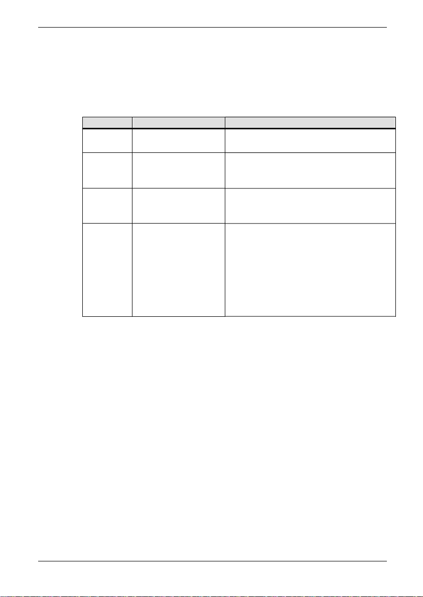
7.4.10 Communications Status P74.09
This parameter displays one of the values shown in Table 7-1
depending upon the state of the PROFIBUS board interface.
Table 7-1 Communications status
Value State Meaning
0 On-line
The PROFIBUS board is
communicating correctly.
The PROFIBUS board has not yet
1 Not configured
been configured with a valid node
address.
The PROFIBUS board has been
2 Network not found
configured, but no network messages
have been detected.
The PROFIBUS board has been
configured, the network Baud rate
deduced from the presence of traffic,
3 Not communicating
but either this slave address is not
being polled from the master, or the
PROFIBUS board does not support
the type of data packet the master is
configured for.
7.4.11 Data Errors P74.10 to P74.13
When transferring data between the PROFIBUS link and the Drive
parameters, several possible errors could occur. If an error does
occur then it is logged in P74.10 or P74.12. Parameters P74.10
and P74.12 log the errors that occurred transferring the data and
P74.11 and P74.13 log the total number of errors. The error format
is as follows:
Bit 0 Reserved
Bit 1 Parameter write access denied, parameter has ‘R’ attribute
set
Bit 2 Data clamped to lower limit before being written
Bit 3 Data clamped to upper limit before being written
Bit 4 Data below bit parameter range and not written
Bit 5 Data above bit parameter range and not written
Bit 6 Reserved
(09/06) Technical Manual Page 7-5
Page 50
7. Menu 74 Parameters ALSPA PROFIBUS Field Bus Coupler
Bit 7 Attempt to write to a stop to edit parameter when running,
data ignored.
Bit 8 Attempt to read from a non-existent parameter
Bit 9 Parameter read access denied.
Bit 10 Reserved
:
:
Bit 15 Reserved
For each transfer all the data errors are flagged, and a counter is
incremented for each transfer error. Note that the error counter is
allowed to rollover and is reset when the PROFIBUS board is
configured. When writing data outside the normal range of a
parameter, the data is clamped to the maximum or minimum value.
Bit parameter values outside the normal range are ignored.
For example if the following information was viewed:
P74.44 = 0300H (= 0000 0011 0000 0000 binary)
P74.45 = 21
This indicates that one of the monitor parameters configured
attempted to read from a non-existent parameter, and another
parameter attempted to read a parameter that did not have Fieldbus
read access. The error counter indicates that a total of 21 errors
had occurred since the last PROFIBUS configuration.
Note that entering a zero as a monitor parameter to be read or
written will not produce an error.
7.4.12 Reference holders P74.20 to P74.38
The PROFIBUS module can provide up to 10 references for use
within the drive. These references can be used to control such
values as the speed (if pointed to by one of the speed reference
pointers). The PROFIBUS reference module needs to be used in
conjunction with Menu 42 (the Pointer Menu), which is described in
Section 6 of the Software Technical Manual T1679.
WARNING:
Ensure that no two Fieldbus parameters are mapped to the
same Drive parameter as this will lead to unpredictable
results.
Page 7-6 Technical Manual (09/06)
Page 51
ALSPA PROFIBUS Field Bus Coupler 7. Menu 74 Parameters
If a loss of PROFIBUS reference is declared, (see Section 7.4.8)
the reference value will no longer be updated by the PROFIBUS
link. In this situation the user has the choice of using the last value
obtained from the PROFIBUS link or using the fallback value.
Each reference has an associated fallback value that will be copied
into the reference value as soon as a loss of PROFIBUS event
occurs. Fallback copying only occurs if the freeze/fallback
parameter is set to fallback.
The fallback value will be valid until the PROFIBUS network
recovers, at which time the PROFIBUS data will be used.
Be aware that the fallback mechanism only applies to values in the
even numbered parameters between P74.20 to P74.42. Received
data transferred directly to Drive parameters will not have the
fallback option but will freeze on loss of the network – refer to the
block diagram at the end of this manual.
Note also that all fallback parameters will be copied to their partner
parameter whether or not the parameter is in use.
Table 7-2 illustrates the relationship between the received PPO
word and the parameter pointers and reference "holders"
(destination parameters) – refer also to the block diagram.
Table 7-2 Received PPO data mapping example for PPO type 4
PPO Reference Parameter Pointer Holder
(Destination Parameter)
PZD1 (STW) P74.50 = 74.40
PZD2 (HSW) P74.52 = 74.20
PZD3 P74.54 = 74.22
PZD4 P74.56 = 74.24
PZD5 P74.58 = 74.26
PZD6 P74.60 = 74.28 or 74.42
Entering a value of 0 in a pointer parameter will mean that any data
associated with that parameter is ignored, as P0.00 is not a valid
parameter.
(09/06) Technical Manual Page 7-7
Page 52

7. Menu 74 Parameters ALSPA PROFIBUS Field Bus Coupler
7.4.13 Control Words P74.40 & P74.42
The PROFIBUS board can provide a source for two control word
parameters. Control flags are explained in the Getting Started
Manual T1676, but basically allow control of such functions as
starting and stopping via a single bit in a 16-bit parameter. The two
control word parameters are capable of controlling 32 control flags.
Normally, only one word of 16 control flags would be sufficient to
control the drive. If more than 16 control flags are needed, P74.42
can be used to hold a further 16 control flags. While any of the
received words can be mapped to this parameter, it is
recommended that the last word be used for the second control
word.
Control flags in the FBC control words are selected by specifying a
control flag source (CFSRC) value in the range 5.000 to 5.031 which
correspond to FBC bits 0 to 31 respectively.
The description of how to map control flag parameters to the drive’s
control flags in Menus 33 and 34 is given in manual T1676, and in
more detail in the Software Technical Manual T1679. The control
flag parameters also have an option of a fallback value if a loss of
Fieldbus reference is declared.
7.4.14 Received Data Parameters P74.50 to P74.69
In order to use the data received in the PPO, it must be placed
somewhere for the drive to use. These Parameters allow the
relevant PPO word to be placed in a destination parameter. While
some parameters can be directly written to, others, such as
references, cannot. For this reason a group of reference
parameters are available to hold the received reference. Menu 42
then points to these references for inclusion into the relevant
reference selector.
Each receive parameter pointer has an associated scale parameter.
This is to allow network units to be converted to drive units.
Internally, the drive represents 100.00% with a value of 10000. The
PROFIDRIVE profile can represent 100.00% with a value of 16384.
In order to scale received set point references to the drive’s internal
representation for 100.00% the parameters in menu 60 (see
7.5)
allow the user to specify what numerical value is being used by the
Page 7-8 Technical Manual (09/06)
Page 53
ALSPA PROFIBUS Field Bus Coupler 7. Menu 74 Parameters
PROFIBUS network to represent 100%. The default scale is set to
unity.
7.4.15 Transmitted Data, P74.70 to P74.89
To put data into the transmit PPO, it must be taken from
somewhere within the drive. Parameters P74.70 to P74.89 allow
the relevant PPO word to be allocated. See Table 7-3.
Table 7-3 Transmitted PPO data mapping example for PPO type 4
Parameter Value Meaning
Example
P74.72 P9.01 = PPO PZD2 (Speed feedback)
P74.73 1 = Speed (%) scaler
P74.70 P(0-99.99) = PPO PZD1
P74.71 0 to 15 = Scaler (0 = unity)
P74.72 P(0-99.99) = PPO PZD2
P74.73 0 to 15 = Scaler (0 = unity)
P74.74 P(0-99.99) = PPO PZD3
P74.75 0 to 15 = Scaler (0 = unity)
P74.76 P(0-99.99) = PPO PZD4
P74.77 0 to 15 = Scaler (0 = unity)
P74.78 P(0-99.99) = PPO PZD5
P74.78 0 to 15 = Scaler (0 = unity)
P74.80 P(0-99.99) = PPO PZD6
P74.81 0 to 15 = Scaler (0 = unity)
The PROFIDRIVE standard specifies that PZD1 (ZSW) contain a
status word following the definition in
Table 7-4. The
Programmable Status Word in P41.32 or P41.33 is a collection of
status bits specified by parameters P41.00 to P41.15, or P41.16 to
P41.31. These can be used to set up the status word required by
PROFIDRIVE, and then point P74.30 to P41.32 or P41.33.
(09/06) Technical Manual Page 7-9
Page 54
7. Menu 74 Parameters ALSPA PROFIBUS Field Bus Coupler
Table 7-4 Allocation of the status word bits (Speed control mode)
Bit Meaning
0 Ready for switch-on / not ready for switch-on
1 Ready for operation / not ready for operation
2 Operation enabled / operation inhibited
3 Fault / no fault
4 No OFF 2 / OFF 2
5 No OFF 3 / OFF 3
6 Switch-on inhibit / no switch-on inhibit
7 Warning / no warning
8
9 Control requested / operation on site
10 speed reached/ speed under range
11 Device-related
12 Device-related
13 Device-related
14 Device-related
15 Device-related
Set point/actual value within tolerance range /
Set point/actual value not within tolerance range
Each location in the PPO sent back to the PROFIBUS master is
specified according to
Table 7-3.
For example, it is decided to monitor 4 parameters, Speed feedback
(P9.01), Current feedback (P9.05), Motor volts (P9.07) and Motor
power (P9.08).
To configure the first parameter source, set P74.72 = 9.01
To configure the first parameter scale, set P74.73 = 1 (speed(%))
To configure the second parameter source, set P74.74 = 9.05
To configure the first parameter scale, set P74.75 = 7 (Current)
To configure the third parameter source, set P74.76 = 9.07
To configure the first parameter scale, set P74.77 = 10 (Volts)
To configure the final parameter source, set P74.78 = 9.08
To configure the first parameter scale, set P74.79 = 6 (Percent)
Note: When entering parameters via the Keypad, it is
important that any leading zeros are entered after the
decimal point. Entering 9.1 will result in P9.10 being
used, not P9.01.
Entering a value of 0 in a source pointer parameter will mean that a
corresponding value of 0 is written to the PROFIBUS network.
Page 7-10 Technical Manual (09/06)
Page 55
ALSPA PROFIBUS Field Bus Coupler 7. Menu 74 Parameters
7.4.16 FBC 1 Config Menu 74
Table 7-5 FBC 1 Config Menu 74
Par No Name Default Range Attrib. Comment
P74 FBC 1 Config Menu
P74.00 Expansionn Bus Device Monitor 3=Fieldbus Coupler R
P74.01 FBC1 Protocol 3 3=PROFIBUS-DP Slave E.L.N.S
P74.02 FBC1 Node Address 0 0 .. 127 E 1..127 for
P74.03 FBC1 PPO Type 4 0=DiL switch
P74.04 Auto Config. FBC1 0 0=Disable
P74.05 Configure FBC1 0 0=Disable
P74.06 Use FBC1 Data. 1 0=Disable
P74.07 Ref. Loss Action 1 0=Ignore
P74.08 FBC1 Fallback Action 1 0= Freeze
P74.09 FBC1 Comms. Status Monitor 0=On-line
P74.10 FBC1 Tx Error Word Monitor 0000 to FFFFhex R.
P74.11 FBC1 Tx Error Count Monitor 0-65535 R
P74.12 FBC1 Rx Error Word Monitor 0000 to FFFFhex R.
P74.13 FBC1 Rx Error Count Monitor 0-65535 R
P74.20 FBC1 Reference 1 0
P74.21 FBC1 Ref. 1 Fallback 0
P74.22 FBC1 Reference 2 0
P74.23 FBC1 Ref. 2 Fallback 0
P74.24 FBC1 Reference 3 0
P74.25 FBC1 Ref. 3 Fallback 0
P74.26 FBC1 Reference 4 0
P74.27 FBC1 Ref. 4 Fallback 0
P74.28 FBC1 Reference 5 0
1=PPO Type 1
2=PPO Type 2
3=PPO Type 3
4= PPO Type 4
5= PPO Type 5
1=Enable
1=Enable
1=Enable
1=Set Warning Bit
2=Trip Drive
1= Fallback
1=Not configured
2=Network not found
3=Not communicating
4=Unknown Protocol
5=Promptness Error
6=Freshness Error
7=Synchronize Error
8=Config. Fault
9=Internal FBK Error
10=Sched. Build Error
11=FBK Scaling Fault
12=Drive Fault
±200.00 %
±200.00 %
±200.00 %
±200.00 %
±200.00 %
±200.00 %
±200.00 %
±200.00 %
±200.00 %
E.L Option 0 for
E.L.N
E.L.N
E.L
E.L
E.L.S
R
E
E
E
E
E
E
E
E
E
PROFIBUS
MVS3007-
4001 boards
only.
(09/06) Technical Manual Page 7-11
Page 56
7. Menu 74 Parameters ALSPA PROFIBUS Field Bus Coupler
Par No Name Default Range Attrib. Comment
P74.29 FBC1 Ref. 5 Fallback 0
P74.30 FBC1 Reference 6 0
P74.31 FBC1 Ref. 6 Fallback 0
P74.32 FBC1 Reference 7 0
P74.33 FBC1 Ref. 7 Fallback 0
P74.34 FBC1 Reference 8 0
P74.35 FBC1 Ref. 8 Fallback 0
P74.36 FBC1 Reference 9 0
P74.37 FBC1 Ref. 9 Fallback 0
P74.38 FBC1 Reference 10 0
P74.39 FBC1 Ref. 10 Fallback 0
P74.40 FBC1 Control Word 1 0 0-FFFF E
P74.41 Control1 Fallback 1. 0 0-FFFF E
P74.42 FBC1 Control Word 2 0 0-FFFF E
P74.43 Control1 Fallback 2. 0 0-FFFF E
P74.50 FBC1 Rx Word 1 Ptr. 00.00 0-99.99 E.N *
P74.51 FBC1 Rx Word 1 Scale 0 0=Unity
P74.52 FBC1 Rx Word 2 Ptr. 00.00 0-99.99 E.N *
P74.53 FBC1 Rx Word 2 Scale 0 0-15 E.L.*
P74.54 FBC1 Rx Word 3 Ptr. 00.00 0-99.99 E.N *
P74.55 FBC1 Rx Word 3 Scale 0 0-15 E.L *
P74.56 FBC1 Rx Word 4 Ptr. 00.00 0-99.99 E.N *
P74.57 FBC1 Rx Word 4 Scale 0 0-15 E.L *
P74.58 FBC1 Rx Word 5 Ptr. 00.00 0-99.99 E.N *
P74.59 FBC1 Rx Word 5 Scale 0 0-15 E.L *
P74.60 FBC1 Rx Word 6 Ptr. 00.00 0-99.99 E.N *
P74.61 FBC1 Rx Word 6 Scale 0 0-15 E.L *
P74.62 FBC1 Rx Word 7 Ptr. 00.00 0-99.99 E.N *
P74.63 FBC1 Rx Word 7 Scale 0 0-15 E.L *
P74.64 FBC1 Rx Word 8 Ptr. 00.00 0-99.99 E.N *
P74.65 FBC1 Rx Word 8 Scale 0 0-15 E.L *
P74.66 FBC1 Rx Word 9 Ptr. 00.00 0-99.99 E.N *
P74.67 FBC1 Rx Word 9 Scale 0 0-15 E.L *
P74.68 FBC1 Rx Word 10 Ptr. 00.00 0-99.99 E.N *
P74.69 FBC1 Rx Word 10 Scale 0 0-15 E.L *
P74.70 FBC1 Tx Word 1 Ptr. 00.00 0-99.99 E.N *
P74.71 FBC1 Tx Word 1 Scale 0 0-15 E.L *
±200.00 %
±200.00 %
±200.00 %
±200.00 %
±200.00 %
±200.00 %
±200.00 %
±200.00 %
±200.00 %
±200.00 %
±200.00 %
1=Speed (%)
2=Speed (RPM)
3=Torque(%)
4=Torque(Nm)
5=Frequency
6= Percent
7=Speed Ramp Rate
8=Torque Slew Rate
9=Current
10=Volts
11=Resistance
12=Inductance
13=Scaler 1
14=Scaler 2
15=Scaler 3
E
E
E
E
E
E
E
E
E
E
E
E.L.*
Page 7-12 Technical Manual (09/06)
Page 57
ALSPA PROFIBUS Field Bus Coupler 7. Menu 74 Parameters
Par No Name Default Range Attrib. Comment
P74.72 FBC1 Tx Word 2 Ptr. 00.00 0-99.99 E.N *
P74.73 FBC1 Tx Word 2 Scale 0 0-15 E.L *
P74.74 FBC1 Tx Word 3 Ptr. 00.00 0-99.99 E.N *
P74.75 FBC1 Tx Word 3 Scale 0 0-15 E.L *
P74.76 FBC1 Tx Word 4 Ptr. 00.00 0-99.99 E.N *
P74.77 FBC1 Tx Word 4 Scale 0 0-15 E.L *
P74.78 FBC1 Tx Word 5 Ptr. 00.00 0-99.99 E.N *
P74.79 FBC1 Tx Word 5 Scale 0 0-15 E.L *
P74.80 FBC1 Tx Word 6 Ptr. 00.00 0-99.99 E.N *
P74.81 FBC1 Tx Word 6 Scale 0 0-15 E.L *
P74.82 FBC1 Tx Word 7 Ptr. 00.00 0-99.99 E.N *
P74.83 FBC1 Tx Word 7 Scale 0 0-15 E.L *
P74.84 FBC1 Tx Word 8 Ptr. 00.00 0-99.99 E.N *
P74.85 FBC1 Tx Word 8 Scale 0 0-15 E.L *
P74.86 FBC1 Tx Word 9 Ptr. 00.00 0-99.99 E.N *
P74.87 FBC1 Tx Word 9 Scale 0 0-15 E.L *
P74.88 FBC1 Tx Word 10 Ptr. 00.00 0-99.99 E.N *
P74.89 FBC1 Tx Word10 Scale 0 0-15 E.L.*
Setting P74.03 to its default will signify the use of the old type of
PROFIBUS FBC. Any other value will imply the use of the new
type.
Where for Attributes:
N - ENTER has to be pressed to update
O - Operator Accessible
E - Engineer Accessible
L - List Parameter
S - Stop Drive To Edit
R - Read Only
∗
This parameter requires a PROFIBUS reconfiguration (P74.05 = 1) before
changes will take effect.
(09/06) Technical Manual Page 7-13
Page 58
7. Menu 74 Parameters ALSPA PROFIBUS Field Bus Coupler
7.5 Scale Menu 60 Description
This menu allows the scaling between drive and Fieldbus to be
specified for various different data types.
A pair of parameters specifies each scale. The first parameter
specifies the drive value equivalent to the external Fieldbus value
contained in the second parameter of the pair. For example, if the
drive represents a value of 100% by the value 10000 and the
Fieldbus represent 100% by the value 16383, the first parameter
will contain 10000 and the second parameter will contain 16383.
When a parameter is to be output to the Fieldbus using the scale
detailed in the above example the formula is:
alueParameterVOutput ×=
alentValueDriveEquiv
lueuivalentVaExternalEq
When receiving a parameter from the Fieldbus the formula is:
InputalueParameterV ×=
alentValueDriveEquiv
lueuivalentVaExternalEq
Table 7-6 lists the data types that have been provided.
Table 7-6 Data Types
Data Type Parameter
Speed(%) P60.00 and P60.01
Speed(rpm) P60.02 and P60.03
Torque(%) P60.04 and P60.05
Torque(Nm) P60.06 and P60.07
Frequency P60.08 and P60.09
Percent P60.10 and P60.11
Speed Ramp Rate P60.12 and P60.13
Torque Slew Rate P60.14 and P60.15
Current P60.16 and P60.17
Volts P60.18 and P60.19
Resistance P60.20 and P60.21
Inductance P60.22 and P60.23
User scaler 1 P60.24 and P60.25
User scaler 2 P60.26 and P60.27
User scaler 3 P60.28 and P60.29
Note: Table 7-7 includes a full list of Menu 60 parameters
Page 7-14 Technical Manual (09/06)
Page 59

ALSPA PROFIBUS Field Bus Coupler 7. Menu 74 Parameters
7.5.1 Scaling Parameter Menu 60
Table 7-7 Scaling Parameter Menu 60
Par No Name Default Range Attrib. Comment
P60.00 Drive Speed (%) 10000
P60.01 Extern Speed (%) 10000
P60.02 Drive Speed (rpm) 1000
P60.03 Extern Speed (rpm) 1000
P60.04 Drive Torque (%) 10000
P60.05 Extern Torque (%) 10000
P60.06 Drive Torque (Nm) 10000
P60.07 Extern Torque (Nm) 10000
P60.08 Drive Frequency 100
P60.09 Extern Frequency 1
P60.10 Drive Percent 10000
P60.11 Extern Percent 10000
P60.12 Drive Ramp Rate 10000
P60.13 Extern Ramp Rate 10000
P60.14 Drive Torque Rate 10000
P60.15 Extern Torque rate 10000
P60.16 Drive Current 10
P60.17 Extern Current 1
P60.18 Drive Volts 1
P60.19 Extern Volts 1
P60.20 Drive Resistance 1
P60.21 Extern Resistance 1
P60.22 Drive Inductance 1
P60.23 Extern Inductance 1
P60.24 Drive Scalar 1 1
P60.25 Extern Scalar 1 1
P60.26 Drive Scalar 2 1
P60.27 Extern Scalar 2 1
P60.28 Drive Scalar 3 1
P60.29 Extern Scalar 3 1
±32,767 pu %
±32,767 pu %
±32,767 pu rpm
±32,767 pu rpm
±32,767 pu %
±32,767 pu %
±32,767 pu Nm
±32,767 pu Nm
±32,767 pu Hz
±32,767 pu Hz
±32,767 pu %
±32,767 pu %
±32,767 pu/s
±32,767 pu/s
±32,767 pu/s
±32,767 pu/s
±32,767 pu A
±32,767 pu A
±32,767 pu V
±32,767 pu V
±32,767 pu Ω
±32,767 pu Ω
±32,767 pu H
±32,767 pu H
±32,767 pu
±32,767 pu
±32,767 pu
±32,767 pu
±32,767 pu
±32,767 pu
E.N
E.N
E.N
E.N
E.N
E.N
E.N
E.N
E.N
E.N
E.N
E.N
E.N
E.N
E.N
E.N
E.N
E.N
E.N
E.N
E.N
E.N
E.N
E.N
E.N
E.N
E.N
E.N
E.N
E.N
7.6 Data Spy Parameters P89.00 to P89.10
The Data Spy parameters can be used to help debug and
commission the PROFIBUS network as well as monitoring data
transactions during normal operation. Using the spy area of Menu
89 it is possible to monitor data received by the module, in its
unmodified form. The data is available in parameters P89.01 to
P89.10 and corresponds to the PZD of the PPO of interest.
(09/06) Technical Manual Page 7-15
Page 60
7. Menu 74 Parameters ALSPA PROFIBUS Field Bus Coupler
The values are displayed in decimal with no scaling and should be
exactly what is appearing on the PROFIBUS network.
To select a PPO to be spied upon, enter the parameter number as
listed in
Table 7-8.
Table 7-8 Data Spy Menu 89
PPO Active Menu P89.00 Value Meaning
Fbus RX PPO Menu 75 75.00 to 75.29
Fbus TX PPO Menu 75 75.30 to 75.46
FBC1 RX PPO Menu 74 74.50 to 74.69
FBC1 TX PPO Menu 74 74.70 to 74.89
Spy Receive PPO
Spy Transmit PPO
Spy Receive PPO
Spy Transmit PPO
Page 7-16 Technical Manual (09/06)
Page 61

ALSPA PROFIBUS Field Bus Coupler 8. Menu 75 Parameters
8. Menu 75 Parameters
8.1 Introduction
This section describes the method of controlling the PROFIBUS
board, using the original drive parameters available in Menu 75.
The section begins with a brief outline of the PROFIBUS protocol
when applied to Variable Speed Drives, followed by a list of the
drive menus used by the PROFIBUS board.
The section gives a list of those parameters necessary to get the
PROFIBUS link working, and then details the functions of the
remaining parameters. The section ends with a list of all the
parameters associated with the PROFIBUS board.
8.2 PROFIBUS Menu
The configuration of the PROFIBUS board is implemented via
Menu 75, which will be visible if the CDC recognises the presence
of a Fieldbus Coupler. Menu 75 is fully described in Section
8.5.
8.3
8.4 Basic Settings Explanation
(09/06) Technical Manual Page 8-1
Data Update Rate
The CDC control board transfers information to and from the
PROFIBUS board every 10 ms. During transfers the software will
interrogate the PROFIBUS board for any errors.
The basic settings are those required to get the PROFIBUS board
operating and to define the basic operating modes of the board.
A block diagram is provided at the end of the manual to help with
configuration of the PROFIBUS board.
The stages in configuring an MVS3007-4001 or MVS3007-4002
PROFIBUS board are as follows:
1. Set up the PROFIBUS network node address in
Parameter 75.02
2. Configure the PROFIBUS references and PROFIBUS
control words in Menu 75.
3. Set P75.05 to 1 to configure the link.
Appendix A gives a worked example.
Page 62

8. Menu 75 Parameters ALSPA PROFIBUS Field Bus Coupler
8.5 Menu 75 Description
8.5.1 Expansion bus device P75.00
The hardware identifier is a read only value that indicates the type
of Expansion board bus fitted to the system. Valid values are:
4 Fieldbus Coupler.
This parameter is also viewable at P35.11.
8.5.2 Node Address P75.02
Each node attached to a PROFIBUS network needs to have a
defined unique node address.
Important: No PROFIBUS board may have the same node
address as another device connected to the same network.
When requested, the PROFIBUS board indicates its presence to
the bus master. If multiple boards are configured with the same
node address they will all try to respond at the same time.
For the PROFIBUS board the node address is defined by P75.02.
The node address may be any number between 2 and 126
inclusive. It is usual for the PROFIBUS master to take node
address 1, and for node address 127 to be reserved for multi-cast
messages.
The PROFIBUS node address can only be reconfigured once
per power up. If the node address needs changing, the new
node address must be programmed and then the drive power
cycled.
8.5.3 Protocol P75.03
Only the PROFIBUS-DP standard is supported, so this parameter
must be set to 3, other options are reserved for other Fieldbus
protocol standards.
Page 8-2 Technical Manual (09/06)
Page 63
ALSPA PROFIBUS Field Bus Coupler 8. Menu 75 Parameters
8.5.4 Run On Power Up P75.04
WARNING
The user should be aware that allowing the PROFIBUS link to
automatically configure and run on power up could represent a
possible safety hazard, as the data from the network will be
acted on by the Drive.
Many users may require the PROFIBUS link to be automatically
configured and run as the drive powers up. This option is available
by setting P75.04 to a 1. This would normally be the last step during
commissioning of the link.
For safety reasons the value of P75.04 is set to a default value of
zero.
8.5.5 Configure Link P75.05
Once the node address has been entered, it is necessary to instruct
the firmware to update the PROFIBUS board’s configuration.
Setting P75.05 to a 1 does this. The firmware automatically rewrites
this value to a zero when configuration is complete. Only after this
occurs will any changes to the board’s configuration take effect.
The PROFIBUS node address can only be reconfigured once
per power up. If the node address needs changing, the new
node address must be programmed and then the drive power
cycled.
If P75.04 was set to a 1 prior to a power-up, setting P75.05 to a 1
will not change the node address until the power is cycled.
8.5.6 Source Loss Action P75.06
A loss of reference may be declared if the PROFIBUS link detects a
loss of communications with the master.
When a loss of reference is declared, one of three things can
happen depending upon the state of P75.06. Valid values of P75.06
are:
0 Ignore loss of reference errors and carry on running.
(09/06) Technical Manual Page 8-3
Page 64

8. Menu 75 Parameters ALSPA PROFIBUS Field Bus Coupler
1 On a loss of reference set a warning and carry on
running.
2 On a loss of reference trip the drive.
The warning code for loss of communications is 116, and the trip
code is 63.
Status flag 56 indicates whether Fieldbus communications are
healthy or not.
8.5.7 Freeze/Fallback Action P75.07
Switch S3-5 (see Section 3.3) must always be set to OFF. In this
condition, P75.07 determines the action taken by the drive if the link
to the PROFIBUS master fails. It affects what values are copied
into the Fieldbus reference parameters defined in Section
7.4.12. If
freeze is selected the parameter value freezes to the last good
received data. If fallback is selected, the associated fallback value
(refer to
Table 8-7, parameters 75.07 to 75.21) is copied into the
appropriate references.
8.5.8
Control Words P75.08 & P75.10
The PROFIBUS board can provide a source for two control word
parameters. Control flags are explained in the Getting Started
Manual T1676, but basically allow control of such functions as
starting and stopping via a single bit in a 16-bit parameter. The two
control word parameters are capable of controlling 32 control flags.
Normally, only one word of 16 control flags would be sufficient,
leaving five words of set-point references. If more than 16 control
flags are needed, P75.10 can be used to hold a further 16 control
flags. While any of the received words can be mapped to this
parameter, it is recommended that the last word be used.
The description of how to map control flag parameters to the drive’s
control flags in Menus 33 and 34 is given in manual T1676, and in
more detail in the Software Technical Manual T1679. The control
flag parameters also have an option of a fallback value if a loss of
Fieldbus reference is declared.
Page 8-4 Technical Manual (09/06)
Page 65
ALSPA PROFIBUS Field Bus Coupler 8. Menu 75 Parameters
8.5.9 Received Data Parameters P75.22 to P75.27
In order to use the data received in the PPO, it must be placed
somewhere for the drive to use. Parameters P75.22 to P75.27 allow
the relevant PPO word to be placed in a destination parameter.
While some parameters can be directly written to, others, such as
references, cannot. For this reason a group of reference
parameters are available to hold the received reference. Menu 42
then points to these references for inclusion into the relevant
reference selector.
8.5.10 References P75.12 to P75.21
The PROFIBUS module can provide up to 5 references for use
within the drive. These references can be used to control such
values as the speed (if pointed to by one of the speed reference
pointers). The PROFIBUS reference module needs to be used in
conjunction with Menu 42 (the Pointer Menu), which is described in
Section 6 of the Software Technical Manual T1679.
To send data from Ref. 1 parameter 1 to PZD1 (P75.12), for
example:
- Set Ref. 1 parameter 1 to point at the reference parameter,
ie. P75.23 = 75.12
The data received at this position will then be copied to P75.12.
WARNING:
Ensure that no two Fieldbus parameters are mapped to the
same Drive parameter as this will lead to unpredictable
results.
If a loss of PROFIBUS reference is declared, (see Section
the reference value will no longer be updated by the PROFIBUS
link. In this situation the user has the choice of using the last value
obtained from the PROFIBUS link or using the fallback value.
In the above example, the fallback value for reference 1 can be set
to 0 by setting P75.13 = 0. To use the fallback value instead of the
last value received over the PROFIBUS link
reference value were linked to the speed reference for example,
7.4.8)
set P75.07 = 1. If this
(09/06) Technical Manual Page 8-5
Page 66
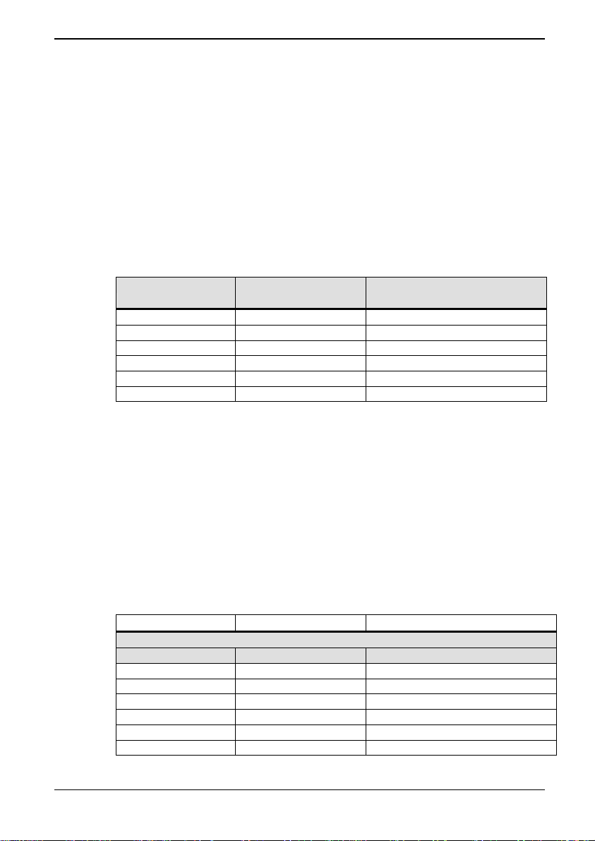
8. Menu 75 Parameters ALSPA PROFIBUS Field Bus Coupler
then upon loss of the PROFIBUS link the speed would automatically
be clamped to zero.
Be aware that the fallback mechanism only applies to values in the
even numbered parameters between P75.08 to P75.20. Received
data transferred directly to Drive parameters will not have the
fallback option but will freeze on loss of the network – refer to the
block diagram at the end of this manual.
Table 7-2 details the relationship between the received PPO word
and the parameter pointers and reference "holders" (destination
parameters) – refer also to the block diagram.
Table 8-1 Received PPO data mapping for PPO type 4
PPO Reference Parameter Pointer Holder
(Destination Parameter)
PZD1 (STW) P75.22 = 75.08
PZD2 (HSW) P75.23 = 75.12
PZD3 P75.24 = 75.14
PZD4 P75.25 = 75.16
PZD5 P75.26 = 75.18
PZD6 P75.27 = 75.10/75.20
Entering a value of 0 in a pointer parameter will mean that any data
associated with that parameter is ignored, as P0.00 is not a valid
parameter.
8.5.11 Transmitted Data, P75.30 to P75.35
To put data into the transmit PPO, it must be taken from
somewhere in the drive. Parameters P75.30 to P75.35 allow the
relevant PPO word to be allocated. See
Table 7-3.
Table 8-2 Transmitted PPO data mapping for PPO type 4
Parameter Value Meaning
Example
P75.31 P9.01 = PPO PZD2 (Speed feedback)
P75.30 P(0-99.99) = PPO PZD1
P75.31 P(0-99.99) = PPO PZD2
P75.32 P(0-99.99) = PPO PZD3
P75.33 P(0-99.99) = PPO PZD4
P75.34 P(0-99.99) = PPO PZD5
P75.35 P(0-99.99) = PPO PZD6
Page 8-6 Technical Manual (09/06)
Page 67
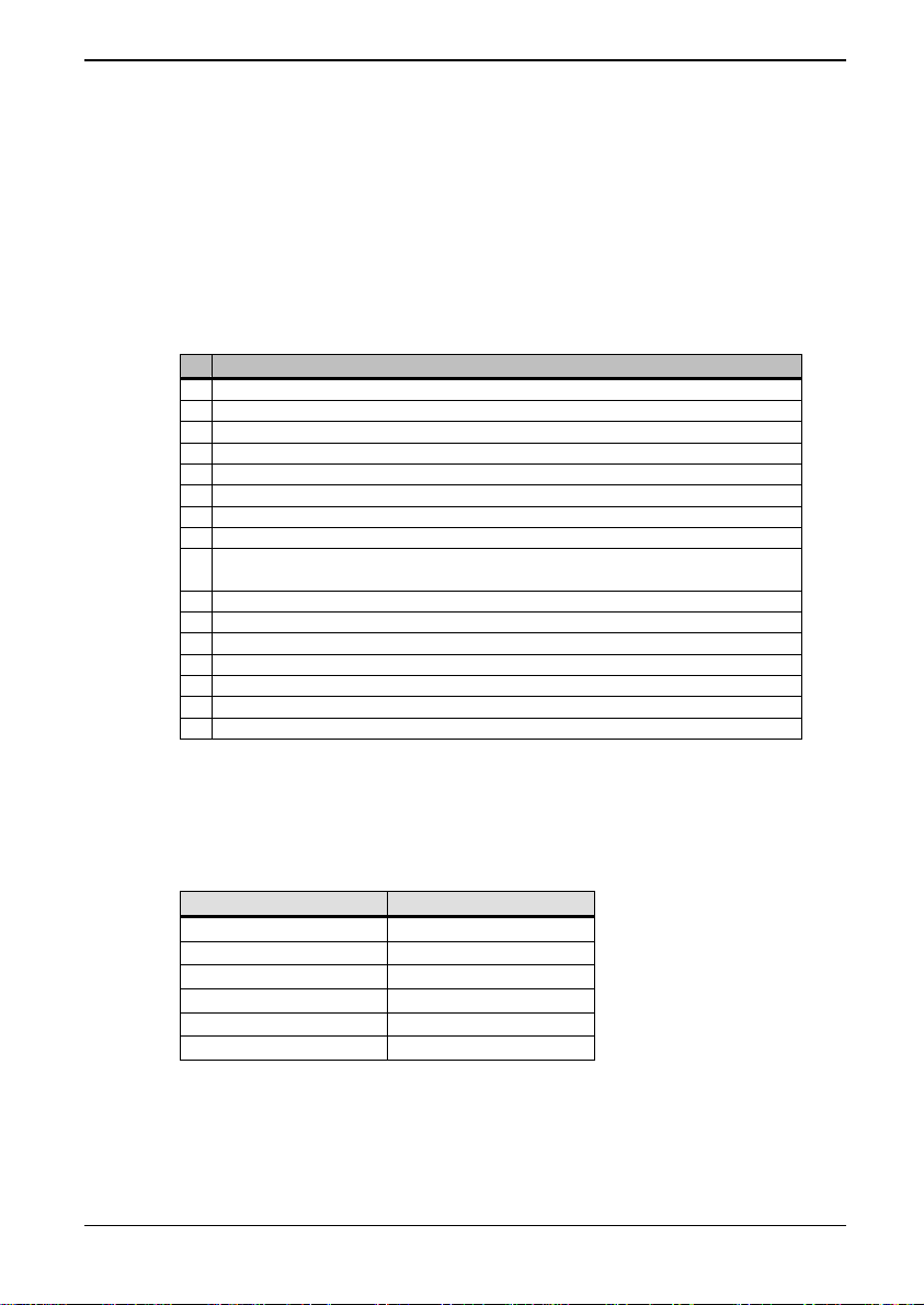
ALSPA PROFIBUS Field Bus Coupler 8. Menu 75 Parameters
The PROFIDRIVE standard specifies that PZD1 (ZSW) contains a
status word following the definition in
Table 7-4. The
Programmable Status Word in P41.32 or P41.33 is a collection of
status bits specified by parameters P41.00 to P41.15, or P41.16 to
P41.31. These can be used to set up the status word required by
PROFIDRIVE, and then point P75.30 to P41.32 or P41.33.
Table 8-3 Allocation of the status word bits (Speed control mode)
Bit Meaning
0 Ready for switch-on / not ready for switch-on
1 Ready for operation / not ready for operation
2 Operation enabled / operation inhibited
3 Fault / no fault
4 No OFF 2 / OFF 2
5 No OFF 3 / OFF 3
6 Switch-on inhibit / no switch-on inhibit
7 Warning / no warning
8
9 Control requested / operation on site
10 speed reached/ speed under range
11 Device-related
12 Device-related
13 Device-related
14 Device-related
15 Device-related
Set point/actual value within tolerance range /
Set point/actual value not within tolerance range
Each location in the PPO sent back to the PROFIBUS master is
specified according to
Table 8-4.
Table 8-4 Transmitted PPO data mapping
PPO Reference Parameter
PZD1 (ZSW) P75.30
PZD2 (HIW) P75.31
PZD3 P75.32
PZD4 P75.33
PZD5 P75.34
PZD6 P75.35
For example, it is decided to monitor 4 parameters, Speed feedback
(P9.01), Current feedback (P9.05), Motor volts (P9.07) and Motor
power (P9.08).
(09/06) Technical Manual Page 8-7
Page 68
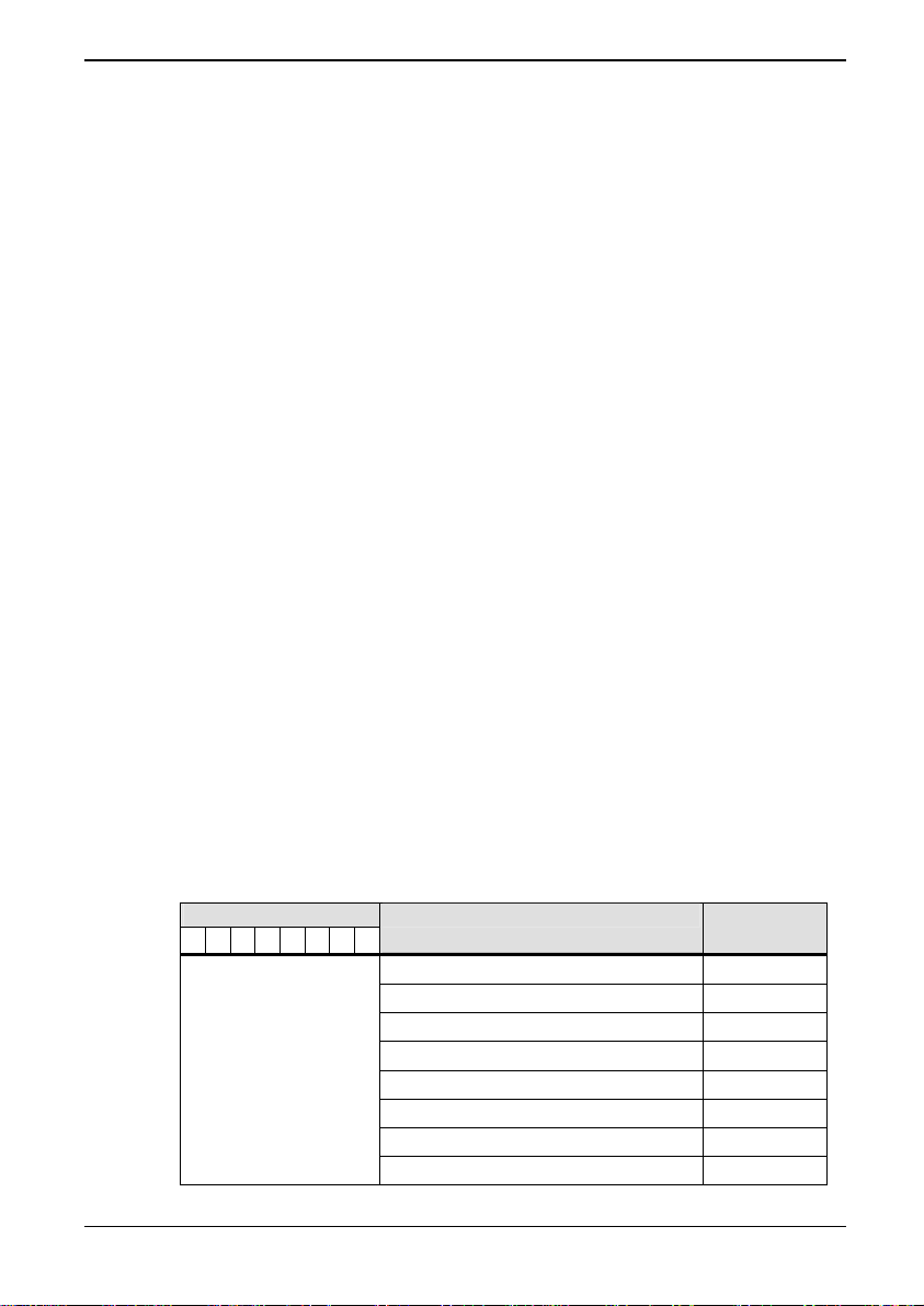
8. Menu 75 Parameters ALSPA PROFIBUS Field Bus Coupler
To configure the first parameter source, set P75.31 = 9.01
To configure the second parameter source, set P75.32 = 9.05
To configure the third parameter source, set P75.33 = 9.07
To configure the final parameter source, set P75.34 = 9.08
Note: When entering parameters via the Keypad, it is
important that any leading zeros are entered after the
decimal point. Entering 9.1 will result in P9.10 being
used, not P9.01.
Entering a value of 0 in a source pointer parameter will mean that a
corresponding value of 0 is written to the PROFIBUS network.
8.5.12 Reference Scaling and Masking, P75.28 to P75.29
Internally, the drive represents 100.00% with a value of 10000. The
PROFIDRIVE profile can represent 100.00% with a value of 16384.
In order to scale received set point references to the drive’s internal
representation for 100.00% the parameter P75.28 is available that
allows the user to specify the numerical value being used by the
PROFIBUS network to represent 100%. At default the value is set
to 10,000.
As not all references may require scaling, a Scale Reference Mask,
P75.29, is provided to enable scaling on selected references. By
default the first and last received words are not scaled as these are
normally used for control flags. The lowest 6 bits in the mask are
used for the scale mask, the remaining bits are ignored.
Table 8-5 Scale reference mask
Bit
76543210
│ │ │ │ │ │ │ └
│ │ │ │ │ │ └ ─
│ │ │ │ │ └ ─ ─
│ │ │ │ └ ─ ─ ─
│ │ │ └ ─ ─ ─ ─
│ │ └ ─ ─ ─ ─ ─
│ └ ─ ─ ─ ─ ─ ─
└ ─ ─ ─ ─ ─ ─ ─
Apply scale to PPO PZD word: Default
─ 1
─ 2
─ 3
─ 4
─ 5
─ 6
─ not used
─ not used
0
1
1
1
1
0
0
0
Page 8-8 Technical Manual (09/06)
Page 69

ALSPA PROFIBUS Field Bus Coupler 8. Menu 75 Parameters
8.5.13 Data Spy Parameters P75.36 to P75.41
5
The Data Spy parameters can be used to help debug and
commission the PROFIBUS board as well as monitoring data
transactions during normal operation. Using the spy area of
Menu 75 it is possible to monitor data received by the module, in its
unmodified form. The data is available in parameters P75.36 to
P75.41 and corresponds to the six 16 bit words of data received by
the module from the PROFIBUS interface.
The values are displayed in decimal with no scaling and should be
exactly what the PROFIBUS-DP Master is transmitting.
8.5.14 Data Errors P75.42 to P75.45
When transferring data between the PROFIBUS link and the Drive
parameters, several possible errors could occur. If an error does
occur then it is logged in P75.42 or P75.44. Parameters P75.42
and P75.44 log the errors that occurred transferring the data and
P75.43 and P75.45 log the total number of errors. The error format
is as follows:
Bit 0 Reserved
Bit 1 Parameter write access denied, parameter has ‘R’
attribute set
Bit 2 Data clamped to lower limit before being written
Bit 3 Data clamped to upper limit before being written
Bit 4 Data below bit parameter range and not written
Bit 5 Data above bit parameter range and not written
Bit 6 Reserved
Bit 7 Attempt to write to a stop to edit parameter when
running, data ignored.
Bit 8 Attempt to read from a non-existent parameter
Bit 9 Parameter read access denied.
Bit 10 - 15 Reserved
For each transfer all the data errors are flagged, and a counter is
incremented for each transfer error. Note that the error counter is
allowed to rollover and is reset when the PROFIBUS board is
configured. When writing data outside the normal range of a
5
The above is correct for software Version 8.00 or earlier.
For software Version 9.00 or later P75.36 to P75.41 are not available.
To view received data set P89.00=P75.00 and view data in P89.01 onward.
For transmitted data set P89.00=P75.30
(09/06) Technical Manual Page 8-9
Page 70
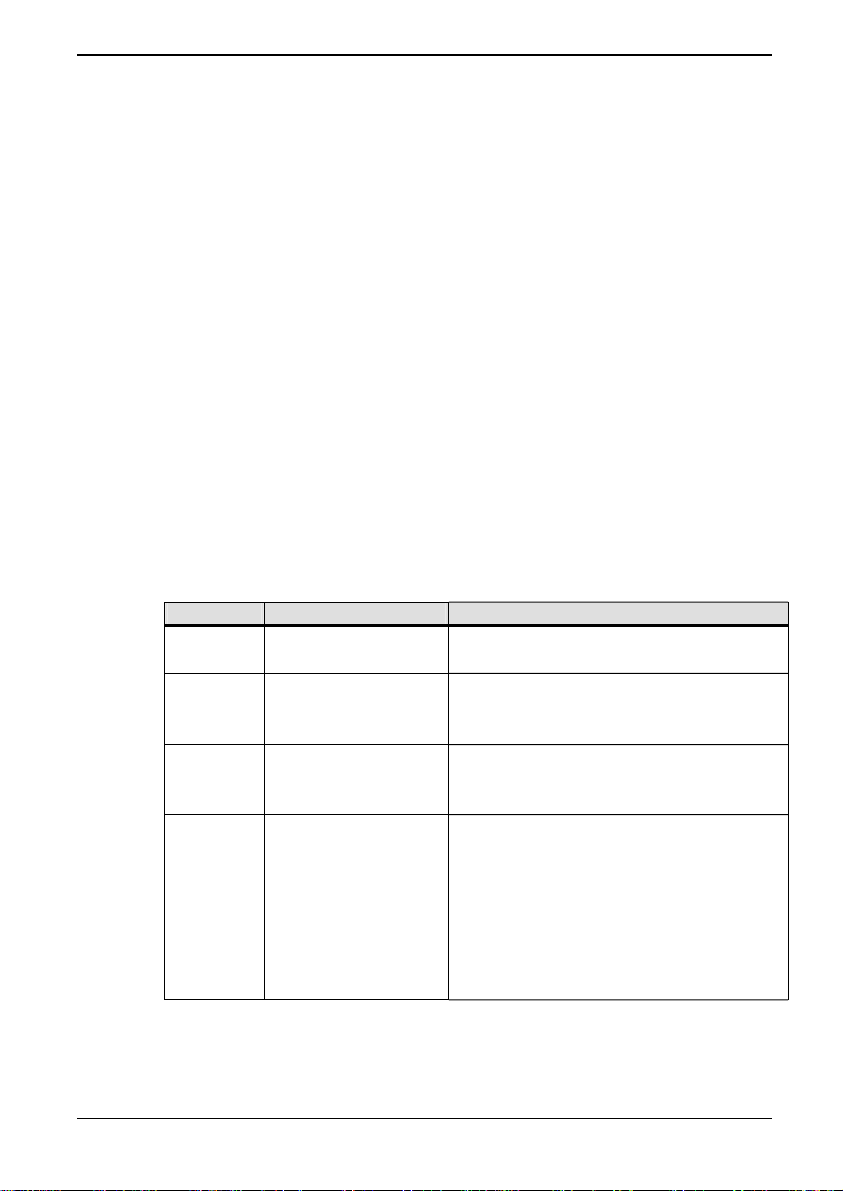
8. Menu 75 Parameters ALSPA PROFIBUS Field Bus Coupler
parameter, the data is clamped to the maximum or minimum value.
Bit parameter values outside the normal range are ignored.
For example if the following information was viewed:
P75.44 = 0300H (= 0000 0011 0000 0000 binary)
P75.45 = 21
This indicates that one of the monitor parameters configured
attempted to read from a non-existent parameter, and another
parameter attempted to read a parameter that did not have Fieldbus
read access. The error counter indicates that a total of 21 errors
had occurred since the last PROFIBUS configuration.
Note: Entering a zero as a monitor parameter to be read or
written will not produce an error.
8.5.15 Communications Status P75.46
This parameter displays one of the values shown in
Table
7-1,depending upon the state of the PROFIBUS board interface.
Table 8-6 Communications status
Value State Meaning
0 On-line
The PROFIBUS board is
communicating correctly.
The PROFIBUS board has not yet
1 Not configured
been configured with a valid node
address.
The PROFIBUS board has been
2 Network not found
configured, but no network messages
have been detected.
The PROFIBUS board has been
configured, the network Baud rate
deduced from the presence of traffic,
3 Not communicating
but either this slave address is not
being polled from the master, or the
PROFIBUS board does not support
the type of data packet the master is
configured for.
Page 8-10 Technical Manual (09/06)
Page 71
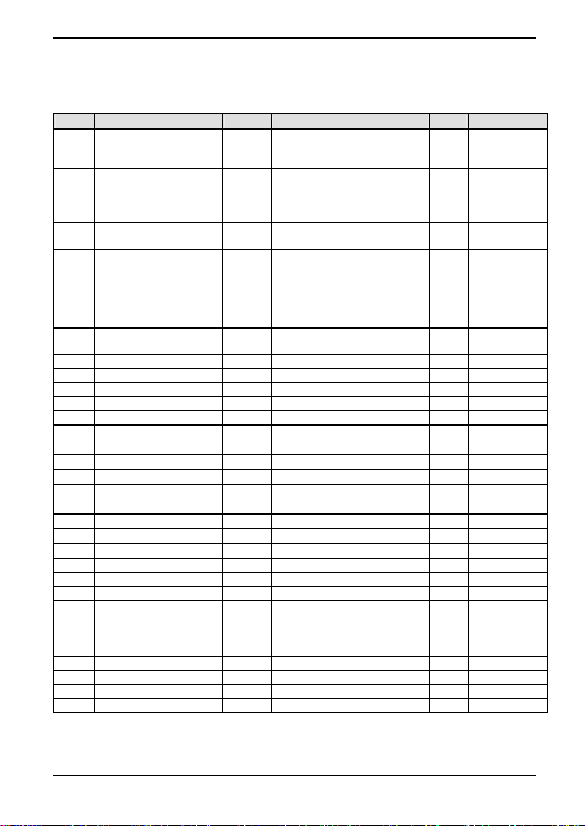
ALSPA PROFIBUS Field Bus Coupler 8. Menu 75 Parameters
8.6 Fieldbus Configuration Menu
Table 8-7 Menu 75
Par No Description Default Range Attr. Comment
75.00 Expansion bus device Set by
75.01 Protocol ID 0 Reserved for future use R Not used
75.02 Node Address 6 255 0 to 127 (4002: 0 to 255) E See page 8-2
75.03 Protocol 3 4002= 2 or 3
75.04 Automatic configuration
at power up
75.05 Configure Link 0 1 to configure. Automatically
75.06 Action on loss of
PROFIBUS control
source.
75.07 Freeze / Fallback 1 0 = Freeze
75.08 Control Word 1 0 0 – FFFF R See page 8-4
75.09 Control Fallback 1 0 0 – FFFF E See page 8-4
75.10 Control Word 2 0 0 – FFFF R See page 8-4
75.11 Control Fallback 2 0 0 – FFFF E See page 8-4
75.12 Reference 1 0
75.13 Fallback 1 0
75.14 Reference 2 0
75.15 Fallback 2 0
75.16 Reference 3 0
75.17 Fallback 3 0
75.18 Reference 4 0
75.19 Fallback 4 0
75.20 Reference 5 0
75.21 Fallback 5 0
75.22 CW 1 Pointer 0 0 - 99.99 E.S.N See page 8-5
75.23 Ref. 1 Pointer 0 0 - 99.99 E.S.N See page 8-5
75.24 Ref. 2 Pointer 0 0 - 99.99 E.S.N See page 8-5
75.25 Ref. 3 Pointer 0 0 - 99.99 E.S.N See page 8-5
75.26 Ref. 4 Pointer 0 0 - 99.99 E.S.N See page 8-5
75.27 CW 2/Ref. 5 Pointer 0 0 - 99.99 E.S.N See page 8-5
75.28 Value for 100% Ref. 10000
75.29 Scale Reference Mask 001Eh 0-FFFFh E.S See page 8-8
75.30 Status word Source 0 0 - 99.99 E.S.N See page 8-6
75.31 Value 1 Source 0 0 - 99.99 E.S.N See page 8-6
75.32 Value 2 Source 0 0 - 99.99 E.S.N See page 8-6
hardware
0 0= Prevent, 1 = Allow E.L See page 7-3
1 0 = Ignore
3 = Fieldbus Coupler R See page 8-2
4001 FIXED= 3
reset to 0 by a configuration
attempt.
1 = Warning
2 = Trip
1 = Fallback
±100.00
±100.00
±100.00
±100.00
±100.00
±100.00
±100.00
±100.00
±100.00
±100.00
0 ±32767
E.L See page 8-2
E.L See page
E.L See page
E.S.L
See page 8-4
E See page 8-5
E See page 8-5
E See page 8-5
E See page 8-5
E See page 8-5
E See page 8-5
E See page 8-5
E See page 8-5
E See page 8-5
E See page 8-5
E See page 8-8
8-3
8-3
6
This parameter requires a PROFIBUS reconfiguration before changes can take
effect.
(09/06) Technical Manual Page 8-11
Page 72
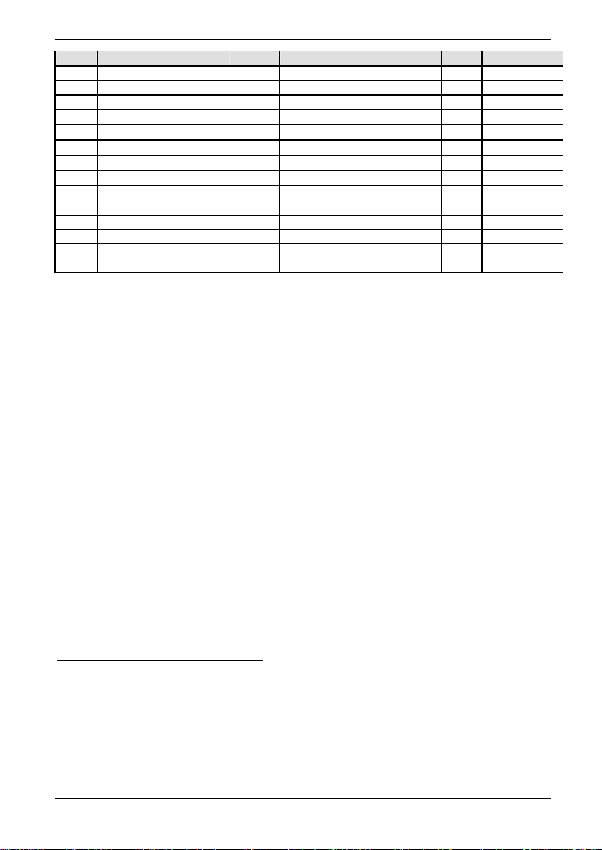
8. Menu 75 Parameters ALSPA PROFIBUS Field Bus Coupler
Par No Description Default Range Attr. Comment
75.33 Value 3 Source 0 0 - 99.99 E.S.N See page 8-6
75.34 Value 4 Source 0 0 - 99.99 E.S.N See page 8-6
75.35 Value 5 Source 0 0 - 99.99 E.S.N See page 8-6
75.36 Raw data 17 0
75.37 Raw data 2
75.38 Raw data 3
75.39 Raw data 4
75.40 Raw data 5
75.41 Raw data 6 4 0
75.42 Rx Error Word R See page 8-9
75.43 Rx Error Count R See page 8-9
75.44 Tx Error Word R See page 8-9
75.45 Tx Error Count R See page 8-9
75.46 Fbus Comms. state 0 - 3 R See page 8-10
4
4
4
4
0
0
0
0
±32767
±32767
±32767
±32767
±32767
±32767
8
5
5
5
5
5
R See page 8-9
R See page 8-9
R See page 8-9
R See page 8-9
R See page 8-9
R See page 8-9
Where for Attributes :
N - ENTER has to be pressed to update
O - Operator Accessible
E - Engineer Accessible
L - List Parameter
S - Stop Drive To Edit
R - Read Only
7
For software Version 8.00 or earlier P75.36 to P75.41 are visible.
For software Version 9.00 or later P75.36 to P75.41 are not available, the SPY facility
should be used as follows:
Received data- Set P89.00=75.00 and view received data in P8900 onwards.
Transmitted data-Set P89.00=75.30 and view data for transmission in P89.01
onwards.
8
Raw data may be received having a value of –32768. This will display as “uncollated”
on the keypad but will nevertheless be transferred correctly.
Page 8-12 Technical Manual (09/06)
Page 73

ALSPA PROFIBUS Field Bus Coupler 8. Menu 75 Parameters
(09/06) Technical Manual Page 8-13
Page 74

Page 75

ALSPA PROFIBUS Field Bus Coupler 9. Maintenance
9. Maintenance
When the PROFIBUS board is installed in a drive, its maintenance
requirements are included with maintenance of the drive, described
in the relevant drive manual. This maintenance consists generally of
checking for the ingress of dust and moisture, and checking for
security of electrical connections.
(09/06) Technical Manual Page 9-1
Page 76

9. Maintenance ALSPA PROFIBUS Field Bus Coupler
This page intentionally left blank
Page 9-2 Technical Manual (09/06)
Page 77
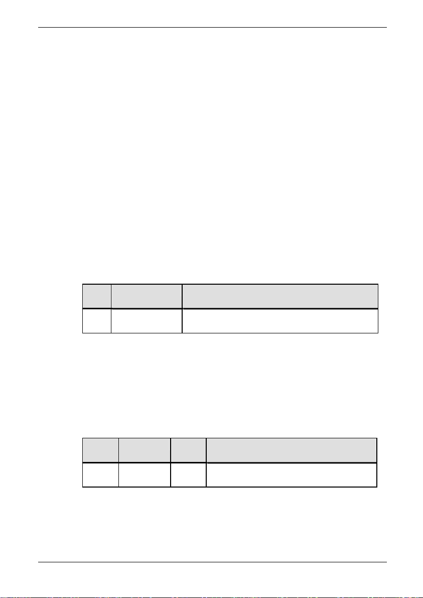
ALSPA PROFIBUS Field Bus Coupler 10. Diagnostics
10. Diagnostics
10.1 Menu 74 Diagnostics
10.1.1 Faults
If a previously working link has stopped working, one of the two
error codes may be displayed depending upon the setting of
P74.07. Status Flag 97 (Fieldbus OK) can also be examined in
parameter P11.35 to confirm the unhealthy state.
10.1.2 PROFIBUS Warning Fault Code
Table 10-1 shows the warning fault code displayed in the drive
warnings tables, if the PROFIBUS link is not healthy, and P74.07;
action on loss of PROFIBUS control source has been set to
"warning".
Table 10-1 Warning fault code
Fault
Name Description
Code
106 FBC1 Loss PROFIBUS board is not communicating
with the master
10.1.3 PROFIBUS Trip Fault Code
Table 10-2 shows the trip fault code displayed in the drive trip
tables, if the PROFIBUS link is not healthy, and P74.07; action on
loss of PROFIBUS control source has been set to "trip".
Table 10-2 Trip fault code
Fault
Name Class Description
Code
204 FBC1
Loss
R PROFIBUS board is not
communicating with the master
A= Auto resettable trip
R = Manually resettable trip
S = System trip
N = Non resettable trip
(09/06) Technical Manual Page 10-1
Page 78
10. Diagnostics ALSPA PROFIBUS Field Bus Coupler
10.2 Menu 75 Diagnostics
10.2.1 Faults
If a previously working link has stopped working, one of the two
error codes may be displayed depending upon the setting of
P75.06. Status Flag 56 (Fieldbus OK) can also be examined in
parameter P11.33 to confirm the unhealthy state.
10.2.2 PROFIBUS Warning Fault Code
Table 10-1 shows the warning fault code displayed in the drive
warnings tables, if the PROFIBUS link is not healthy, and P75.06;
action on loss of PROFIBUS control source has been set to
"warning".
Table 10-3 Warning fault code
Fault
Name Description
Code
116 Fieldbus Loss PROFIBUS board is not communicating
with the master
10.2.3 PROFIBUS Trip Fault Code
Table 10-2 shows the trip fault code displayed in the drive trip
tables, if the PROFIBUS link is not healthy, and P75.06; action on
loss of PROFIBUS control source has been set to "trip".
Table 10-4 Trip fault code
Fault
Name Class Description
Code
63 Fieldbus
Loss
A, R PROFIBUS board is not
communicating with the master
A= Auto resettable trip
R = Manually resettable trip
S = System trip
N = Non resettable trip
Page 10-2 Technical Manual (09/06)
Page 79
ALSPA PROFIBUS Field Bus Coupler 10. Diagnostics
10.3 MVS3007-4001 and MVS3007-4002 Fieldbus Coupler Indicator
LEDs
The MVS3007-4001 and MVS3007-4002 PROFIBUS Fieldbus Couplers
provide two LED indicators for diagnostic purposes. These are not
visible from the outside of the drive, but are visible on the edge of the
board when the Drive control door is open. They are viewed end-on as
shown in
Figure 10-1) and have meanings as shown in Table 10-5.
Off = Network found
Flickering = Baud rate seeking
Slow flash = Watchdog acting
On = Not yet configured
H3
10.4
On = Ready for o p eration
Slow flash = Watchdog acting
Figure 10-1 Diagnostic LEDs on the PROFIBUS board
Table 10-5 LED indication meaning
H2
LED H2 LED H3 Description
On On Node address not yet configured
On Flickering
Searching for any network traffic.
On Off Network traffic found.
Pulsing Pulsing Watchdog time-out.
Depending on the setting of Switch S2 parameter P75.46 or
parameter P74.09 will display the state of the communications
without opening the drive to view the LEDs, see Section
7.4.10.
Spares and Re-order Information
The interface does not contain any user replaceable parts and must
be returned to the manufacturer for repair. Whole units should be
kept for spares.
Please contact customer support, or your local agent for details.
The MVS3007-4001 PROFIBUS board is no longer available.
The order number for the replacement PROFIBUS board is:
MVS3007-4002
(09/06) Technical Manual Page 10-3
Page 80

10. Diagnostics ALSPA PROFIBUS Field Bus Coupler
This page intentionally left blank
Page 10-4 Technical Manual (09/06)
Page 81

ALSPA PROFIBUS Field Bus Coupler Appendix A.Configuration Example
Appendix A. Configuration Example
Consider a drive on a PROFIBUS network that requires a Run/Stop
command, speed reference and minimum speed set via the
PROFIBUS network. The drive produces its speed feedback and
torque demand onto the PROFIBUS network. This drive is to have
a PROFIBUS node address of 10.
Realistically Run/Stop and speed reference would probably be a
‘global’ requirement for other drives on the network, whereas
minimum speed may only be required individually.
The drive first needs to be commissioned to run the motor, so carry
out the commissioning procedure in the MV3000e technical
manuals. Assuming the drive and PROFIBUS board are correctly
installed, the PROFIBUS now needs to be configured.
Refer to the block diagram at the rear of this manual to visualise the
parameters and their uses.
A.1 Check the PROFIBUS Hardware
P75.00 indicates which type of Fieldbus Coupler board is fitted.
This should display a 3, corresponding to a Fieldbus Coupler board.
If P75.00 is not visible, check P35.11 it will display the type of
expansion board fitted. If it displays 0 corresponding to no
expansion board, verify that the PROFIBUS board is fitted correctly.
If it displays some other type of expansion board, check that the
correct board is fitted.
If the correct board is fitted and LED H2 and H3 are lit according to
Table 10-5 LED indication meaning in Section 10.3 MVS3007-4001
and MVS3007-4002 Fieldbus Coupler Indicator LEDs, both LEDs
should be illuminated to indicate an un-configured, healthy
PROFIBUS board.
A.2
Decide what information needs to be transferred.
For a more complex set of data to be transferred, the tables
contained in
allocation of the parameters. In this example, the requirements are
simple, so we will move directly to the next stage.
Appendix B Configuration Tables may help in the
(09/06) Technical Manual Page A1
Page 82
Appendix A.Configuration Example ALSPA PROFIBUS Field Bus Coupler
A.3 Configure the PROFIBUS Link
To configure this information into the drive, the following parameters
need to be set:
Table A-1 Basic set-up
Parameter Value Meaning
P75.02 10 Set the node address to 10
P75.06 is set to warn until the link has been fully commissioned, at
which time it can be set to the desired state.
To configure the drive set P75.05 to a 1. This will be rewritten to a
zero when configuration has been completed. With the PROFIBUS
link disconnected, or if the PROFIBUS master has not yet been
configured to communicate with slave 10, LED H3 will change from
steady to either flashing (no traffic detected on the network), or off
(traffic detected on the network). At the same time the warning LED
on the keypad will illuminate. When the PROFIBUS-DP Master has
been correctly configured for slave 10, with the correct packet
length, the warning LED will extinguish.
Note: Setting P75.04 to a 1 allows the PROFIBUS board to
be automatically configured as the drive powers up.
Baud rate: There is no Baud rate selection as the Slave
automatically Baud selects to the rate of the Master,
however the valid values are shown in Section 2.1.1.
A.4 Adding Drive Parameters
Having configured the PROFIBUS link it is then necessary to
configure where the information to be transmitted over the link
comes from and received information goes to. There are three basic
types of data parameters: simple parameters, references and
control/status bits.
A.5 Simple Parameters
Simple parameters are parameters that the PROFIBUS board can
write to or read from directly. In this example the minimum speed,
speed feedback and torque demand are examples of simple
parameters.
To transmit simple parameters out onto the link, enter the
parameter number into the appropriate Transmit parameter. The
set-up for monitored values would be as in Table A-2 below.
Page A2 Technical Manual (09/06)
Page 83
ALSPA PROFIBUS Field Bus Coupler Appendix A.Configuration Example
Example for transmitted/monitored data
Table A-2 Simple monitor parameter set-up.
Parameter Value Meaning
P75.31 9.01 PPO PZD2 – P9.01 Speed
feedback
P75.32 9.04 PPO PZD3 – P9.04 Torque
demand
P75.33 0 PPO PZD4 – not required
P75.34 0 PPO PZD5 – not required
P75.35 0 PPO PZD6 – not required
Speed Feedback and Torque Demand will be transmitted from the
drive onto the PROFIBUS link.
Received Data
This example also has a simple reference parameter, P5.17
minimum speed. P75.24 is configured below in Table A-3.
Note that the minimum speed parameter P5.17 and its units are in
rpm, not percentage. The drive is connected to a 1500 r/min motor.
To write to parameters within the drive, enter the parameter number
into the appropriate Receive parameter.
Table A-3 Simple reference parameter set-up.
Parameter Value Meaning
P75.24 5.17 PPO PZD3 - P5.17 minimum speed
This will allow the PROFIBUS link to write directly to the minimum
speed parameter.
A.6 Reference Parameters
References are parameters within the drive that cannot be written to
directly, speed reference is one such example. In order to have
PROFIBUS data as the speed reference it is necessary to write the
PROFIBUS data to a PROFIBUS reference and then select this
reference to be the speed reference.
The first stage to setting up a reference parameter is to produce a
PROFIBUS reference. PROFIBUS references are held in P75.12 to
P75.21. Even numbers contain the reference, odd numbers contain
the fallback for the reference. In this example we will use
(09/06) Technical Manual Page A3
Page 84
Appendix A.Configuration Example ALSPA PROFIBUS Field Bus Coupler
PROFIBUS reference 1, see Table A-4. The received data is
transferred using the Reference Pointers in P75.23 to P75.27.
In this example we will use Reference Pointer 1 to transfer the
Speed Reference, Reference Pointer 2 retains its configuration from
the above "simple example".
Table A-4 Reference parameter set-up
Parameter Value Meaning
P75.23 75.12 Ref. 1 = P75.12 = PPO PZD2 word
P75.24 5.17 PPO PZD3 - P5.17 minimum speed
P75.25 0 PPO PZD4 word not used
P75.26 0 PPO PZD5 word not used
P75.27 0 PPO PZD6 word not used
Having configured the P75.23 pointer to transfer data to a Fieldbus
reference "holder", the user has the option of declaring a ‘fallback’
value for that reference. This will be dealt with later.
Reference Scaling and Masking
The ‘holder’ for the received reference can only have a value of
±100.00%, which internally is represented as ±10000. It is
necessary to enter a value of 10,000 into P75.28 to make the drive
scale a received value of 10,000 into 10000. As the scaling will
apply only to the first reference, the second and third bits in the
Scale Reference Mask, P75.29, need to be a ‘1’ and a ‘0’
respectively. The default setting, where the second, third, fourth and
fifth bits are ‘1’, so P75.29 must be changed to read
0000000000000010 binary which is 0002H. It is necessary to know
the hexadecimal value as the parameter requires the value to be
entered as hexadecimal.
Once the PROFIBUS reference has been configured it is necessary
to configure the speed reference to come from the Fieldbus
Reference 1. Each of the drive references has a parameter or
parameters that set-up where the source of that reference is. For
the speed references these parameter are P5.01 to P5.05. These
parameters need to be configured to source the reference from the
‘Pointer menu’, Menu 42. Each of the pointers in Menu 42 is
dedicated to one of the drive references. The speed reference has
pointers 1 and 2 dedicated to it. We will use pointer 1, see Table A-
5.
Page A4 Technical Manual (09/06)
Page 85
ALSPA PROFIBUS Field Bus Coupler Appendix A.Configuration Example
Table A-5 Speed reference set-up
Parameter Value Meaning
P5.01 21 Speed reference source 1 - use pointer 1
P5.02 0 Speed reference source 2 - not required
P5.03 0 Speed reference source 3 - not required
P5.04 0 Speed reference source 4 - not required
P5.05 0 Speed backup source – not required
Having configured the speed reference source to be menu 42
pointer 1, the final stage is to configure pointer 1 to use PZD1, set
up previously. Pointer 1 is configured in P42.00 and P42.01 as
shown in Table A-6 below.
Table A-6 Speed reference pointer 1 set-up
Parameter Value Meaning
P42.00 75.12 Pointer 1 source – P75.12 Fieldbus
reference 1
P42.01 100.00 Pointer 1 scale - 100.00%
The data transferred in the Fieldbus Reference 1 word (from PPO
PZD2) will now be used as the speed reference. Note that menu 42
allows the use of a scaling function to scale the incoming data
before it is written to the relevant reference. This scale will also
apply to the fallback value if it used.
A.7 Control Bits
Control bits are bits in the drive that cannot be written to directly, but
may be accessed indirectly in a similar manner to a reference.
Control bits perform such tasks as starting and stopping the drive.
This example requires access to 2 control bits, the start flag and the
stop flag. The first stage to setting up a control bit is to produce a
Fieldbus control word, which is similar to a Fieldbus reference.
Fieldbus control words are held in P75.08 and P75.10. Control word
1 (from PPO PZD1) is used in this example and control word 2
(from PZD6) may also be used. Here we will use control word 1
only, the set-up being shown in Table A-7. The start and stop bits
are transferred using control word 1.
(09/06) Technical Manual Page A5
Page 86
Appendix A.Configuration Example ALSPA PROFIBUS Field Bus Coupler
Table A-7 Control word set-up
Parameter Value Meaning
P75.22 75.08 Control word 1 = P75.08 = PPO PZD1.
P75.27 0 PPO PZD6 word not used.
Having configured the parameters to transfer data to a Fieldbus
control reference the user has the option of declaring a ‘fallback’
value for that control reference. This will be dealt with later.
Once the Fieldbus control reference has been configured it is
necessary to configure the start and stop control bits source to
come from Fieldbus control reference 1. Each of the drive control
bits has a parameter that sets up where the source of that control
bit is. Referring to Table A-8, for the start bit this parameter is
P33.01 for the stop bit this parameter is P33.00. These parameters
need to be configured to source their values from the Fieldbus
control reference. Fieldbus control reference 1 contains values
5.100 to 5.115 which are Fieldbus control reference 1 bits 0 to 15,
values 5.200 to 5.215 are Fieldbus control reference 2 bits 0 to 15.
Table A-8 Control flag source set-up
Parameter Value Meaning
P33.00 5.100 Stop control flag source - 5.100 Fieldbus
control word 1, bit 0
P33.01 5.101 Start control flag source - 5.101 Fieldbus
control word 1, bit 1
P34.16 1 Pass Start/Stop control to the control flags
A.8 Status Word
Any drive status word can be sent to the Fieldbus, either a predefined one from Menu 11 or a user-configured one from Menu 41.
This example, shown in Table A-9, will send the first 16 Status
Flags in P11.30, (as TX STS WRD 1 SOURCE).
Table A-9 Transmit status word
Parameter Value Meaning
Page A6 Technical Manual (09/06)
Page 87
ALSPA PROFIBUS Field Bus Coupler Appendix A.Configuration Example
P75.30 11.30 Transmitted status word 1 source
The Fieldbus parameters now contain a basic configuration.
A.9 Data for Master Device Configuration
The PROFIBUS-DP master device producing the data for this drive
should now be configured. The data required to get the drive
running is shown in Table A-10.
Table A-10 PROFIBUS-DP Master’s data allocation
Word
Value Meaning
0 XXXXH Contains the run/stop bits
1 5000 Set the speed reference to 50%
2 150 Set the drive minimum speed to 150 rpm
3 0 Not used
4 0 Not used
5 0 Not used
The data produced by the drive is listed in Table A-11 below:
Table A-11 PROFIBUS-DP Master’s received data
Word Units Meaning
0 Binary flags Contains the drive status bits
1 0.01% Speed feedback.
2 0.01% Torque demand.
3 0 Not used
4 0 Not used
5 0 Not used
A.10 Using PROFIBUS Data Spy
Having parameterised a basic configuration, the user may wish to
know what data is actually being transferred over the PROFIBUS
network. This can be done using the PROFIBUS spy module. The
PROFIBUS spy module uses P75.36 to P75.41 to display each of
the 6 PZD words associated with the received PPO.
(09/06) Technical Manual Page A7
Page 88
Appendix A.Configuration Example ALSPA PROFIBUS Field Bus Coupler
Note that the data will be displayed un-scaled and in decimal. The
drive may limit data before writing it into a parameter if it exceeds
that parameter’s limits, see Section
7.4.11.
A.11
Check For Data Errors
Once the drive has been configured the user should check that no
data errors are occurring. Data errors can occur when the
PROFIBUS module attempts to write the data from the PPO into
drive parameters. This may be because the parameter is not able to
accept data in this manner, or because the data itself is outside
accepted limits. Data errors are given in P75.42 to P75.45. For the
receive and transmit PPO packets there is an error code of the last
error that occurred and the number that have occurred since the
last PROFIBUS configuration attempt. The list of data error codes
and their meaning is given in Section
7.4.11. An example for the
source data is given in Table A-12 below.
Table A-12 Data error example
Parameter Value Meaning
P75.44 200H Read access from a parameter was
denied
P75.45 20 20 errors have occurred since the
last PROFIBUS link configuration.
In this example read access to a parameter was denied, possibly
because that parameter does not exist. This implies that one of the
parameters set for source is incorrect and does not actually exist.
A.12 Fallback Values
The example declares a PROFIBUS reference and a PROFIBUS
control word, both of which have the option of a fallback value. A
fallback value is a value that will be used instead of the PROFIBUS
value if the PROFIBUS link becomes unhealthy. As a simple
example, if the PROFIBUS link is lost then the user may want to
force the speed reference to zero. To use this feature the
PROFIBUS link first needs to be configured to select fallback value
Page A8 Technical Manual (09/06)
Page 89
ALSPA PROFIBUS Field Bus Coupler Appendix A.Configuration Example
on a loss of the PROFIBUS link. Setting parameter P75.07 to a 1
does this.
If this value is set to 0 then on a PROFIBUS loss the reference
value will be frozen. This means that the last valid value received
over the link will be used.
Note: ALL PROFIBUS reference/control values are affected by
the freeze/fallback simultaneously.
The fallback values can now be entered for the relevant PROFIBUS
reference, for the speed reference we will use a fallback value of 0.
If communication is lost then we would like the drive to stop, this
means that the start control flag should be set to 0, and the stop bit
should be set to 0. This means the fallback value should be 0000H.
These settings are summarised in Table A-13.
Table A-13 Fallback value example
Param Value Meaning
P75.07 1 On PROFIBUS loss use the fallback
not the freeze value
P75.13 0 PROFIBUS reference 1 (speed
reference) fallback value
P75.09 0000H PROFIBUS control word 1 (start/stop
flags) fallback value.
Bit 0 - Not set, stop flag active
Bit 1 - Not set, start flag inactive
Bits 2 - 15 – not required
A.13 Warning on Loss of PROFIBUS Link
This function is carried out by P75.06 (described in Section 7.4.8).
During the commissioning process P75.06 is set to 1 by default, and
the drive generates a Warning. When commissioning has been
successfully completed, P75.06 may be set to either :
0 = Ignore loss
1 = Warn of loss
2 = Trip the drive
(09/06) Technical Manual Page A9
Page 90

Appendix A.Configuration Example ALSPA PROFIBUS Field Bus Coupler
This page intentionally left blank
Page A10 Technical Manual (09/06)
Page 91
ALSPA PROFIBUS Field Bus Coupler Appendix B. Configuration Tables
Appendix B. Configuration Tables
Table B-1 PROFIBUS control words
No. Param. Mapped
From
Example
1 P74.40 74.50 0
1 P74.40
2 P74.42
Table B-2 Control Word 1, P74.40
Bit Control Flag
Number
Example
0 5.000 0 Bit 0 mapped to Stop flag
0 5.000
1 5.001
2 5.002
3 5.003
4 5.004
5 5.005
6 5.006
7 5.007
8 5.008
9 5.009
10 5.010
11 5.011
12 5.012
13 5.013
14 5.014
15 5.015
Fallback
Value
Fallback
Value
Description
Description
(09/06) Technical Manual Page B1
Page 92
Appendix B. Configuration Tables ALSPA PROFIBUS Field Bus Coupler
Table B-4 Control Word 2, P74.40
Bit Control Flag
Number
Example
0 5.016 0 Bit 0 mapped to Stop flag
0 5.016
1 5.017
2 5.018
3 5.019
4 5.020
5 5.021
6 5.022
7 5.023
8 5.024
9 5.025
10 5.026
11 5.027
12 5.028
13 5.029
14 5.030
15 5.031
Table B-3 PROFIBUS References
No. Param. Destination
Parameter
Example
1 P74.50 74.20 0 0 Speed Reference
1 P74.50
2 P74.52
3 P74.54
4 P74.56
5 P74.58
6 P74.60
7 P74.62
8 P74.64
9 P74.66
10 P74.68
Fallback
Value
Scale Fallback
Description
Value
Description
Page B2 Technical Manual (09/06)
Page 93
ALSPA PROFIBUS Field Bus Coupler Appendix B. Configuration Tables
Table B-5 PROFIBUS monitors
No. Param. From
Parameter
Example
1 P74.70 41.32 0 0 Prog status word 0
2 P74.72 9.01 0 0 Speed Feedback
1 P74.70
2 P74.72
3 P74.74
4 P74.76
5 P74.78
6 P74.80
7 P74.82
8 P74.84
9 P74.86
10 P74.88
Table B-6 Programmable Status Word 0
Bit Param.
No.
Example
0 P41.00 2.001 Bit 0 mapped to Stopped flag
0 P41.00
1 P41.01
2 P41.02
3 P41.03
4 P41.04
5 P41.05
6 P41.06
7 P41.07
8 P41.08
9 P41.09
10 P41.10
11 P41.11
12 P41.12
13 P41.13
14 P41.14
15 P41.15
Control
Flag No.
Description
Scale Fallback
Value
Description
(09/06) Technical Manual Page B3
Page 94
Appendix B. Configuration Tables ALSPA PROFIBUS Field Bus Coupler
Table B-7 Programmable Status Word 1
Bit
Param.
No.
Example
0 P41.16 2.001 Bit 0 mapped to Stopped flag
0 P41.16
1 P41.17
2 P41.18
3 P41.19
4 P41.20
5 P41.21
6 P41.22
7 P41.23
8 P41.24
9 P41.25
10 P41.26
11 P41.27
12 P41.28
13 P41.29
14 P41.30
15 P41.31
Table B-8 Menu 42 - Reference Pointers
Control
Flag No.
Description
No. Param. Points
To
Param.
Example
1 P42.00 74.12 10000 Speed Reference
1 P42.00 Speed Reference
2 P42.02 Speed Reference
3 P42.04 Reference Sequencer
4 P42.06 PID Set-point
5 P42.08 PID Feedback
6 P42.10 Trim Reference
7 P42.12 Speed Trim Reference
8 P42.14 Torque Reference
9 P42.16 Torque Limits
10 P42.18 Torque Limits
11 P42.20 Temperature Compensation Scale
12 P42.22 Flux Limit
13 P42.24 Current Limit
14 P42.26 Torque/Magnet. Current
15 P42.28 Torque/Magnet. Current
16 P42.30 Position Reference
17 P42.32 Position Reference
Scale Function
Page B4 Technical Manual (09/06)
Page 95
ALSPA PROFIBUS Field Bus Coupler Appendix B. Configuration Tables
18 P42.34 Tacho Feedback
Table B-1 PROFIBUS control words
No. Param. Mapped
From
Example
1 P75.08 75.22 0
1 P75.08
2 P75.00
Table B-2 Control Word 1, P75.08
Bit Control Flag
Number
Example
0 5.100 0 Bit 0 mapped to Stop flag
0 5.100
1 5.101
2 5.102
3 5.103
4 5.104
5 5.105
6 5.106
7 5.107
8 5.108
9 5.109
10 5.110
11 5.111
12 5.112
13 5.113
14 5.114
15 5.115
Table B-3 PROFIBUS References
Fallback
Value
Fallback
Value
Description
Description
No. Param. Destination
Parameter
Example
1 P75.23 75.12 0 Speed Reference
1 P75.23
2 P75.24
3 P75.25
4 P75.26
5 P75.27
Fallback
Value
Description
(09/06) Technical Manual Page B5
Page 96
Appendix B. Configuration Tables ALSPA PROFIBUS Field Bus Coupler
Table B-4 Control Word 2, P75.10
Bit Control Flag
Number
Example
0 5.200 0 Bit 0 mapped to Stop flag
0 5.200
1 5.201
2 5.202
3 5.203
4 5.204
5 5.205
6 5.206
7 5.207
8 5.208
9 5.209
10 5.210
11 5.211
12 5.212
13 5.213
14 5.214
15 5.215
Table B-5 PROFIBUS monitors
No. Param. From
Param.
Example
1 P75.30 41.32 Prog status word 0
1 P75.30
2 P75.31
3 P75.32
4 P75.33
5 P75.34
6 P75.35
Fallback
Value
Description
Description
Page B6 Technical Manual (09/06)
Page 97
ALSPA PROFIBUS Field Bus Coupler Appendix B. Configuration Tables
Table B-6 Programmable Status Word 0
Bit Param.
No.
Example
0 P41.00 2.001 Bit 0 mapped to Stopped flag
0 P41.00
1 P41.01
2 P41.02
3 P41.03
4 P41.04
5 P41.05
6 P41.06
7 P41.07
8 P41.08
9 P41.09
10 P41.10
11 P41.11
12 P41.12
13 P41.13
14 P41.14
15 P41.15
Control
Flag No.
Description
Table B-7 Programmable Status Word 1
Bit
Param.
No.
Example
0 P41.16 2.001 Bit 0 mapped to Stopped flag
0 P41.16
1 P41.17
2 P41.18
3 P41.19
4 P41.20
5 P41.21
6 P41.22
7 P41.23
8 P41.24
9 P41.25
10 P41.26
11 P41.27
12 P41.28
13 P41.29
Control
Flag No.
Description
(09/06) Technical Manual Page B7
Page 98
Appendix B. Configuration Tables ALSPA PROFIBUS Field Bus Coupler
14 P41.30
15 P41.31
Table B-8 Menu 42 - Reference Pointers
No. Param. Points
Scale Function
To
Param.
Example
1 P42.00 75.12 10000 Speed Reference
1 P42.00 Speed Reference
2 P42.02 Speed Reference
3 P42.04 Reference Sequencer
4 P42.06 PID Set-point
5 P42.08 PID Feedback
6 P42.10 Trim Reference
7 P42.12 Speed Trim Reference
8 P42.14 Torque Reference
9 P42.16 Torque Limits
10 P42.18 Torque Limits
11 P42.20 Temperature Compensation Scale
12 P42.22 Flux Limit
13 P42.24 Current Limit
14 P42.26 Torque/Magnet. Current
15 P42.28 Torque/Magnet. Current
16 P42.30 Position Reference
17 P42.32 Position Reference
18 P42.34 Tacho Feedback
Page B8 Technical Manual (09/06)
Page 99

ALSPA PROFIBUS Field Bus Coupler Appendix C. Fault Return Form
Appendix C. Fault Return Form
(09/06) Technical Manual Page C1
Page 100

Appendix C. Fault Return Form ALSPA PROFIBUS Field Bus Coupler
Product Failure Notification
Customer:
Address:
Fax No:
Tel No:
Date:
Ship to Address (if different to
above):
Description of Item
PCB/Unit Type:
Serial No:
Description:
System Type:
Fault occurs when (please tick)
Hot Cold Ambient
Type of Fault (please tick)
Hard Intermittent
Time between failures
_______________ hours/minutes
Fault Code displayed
________________
End User Details
Name:
Address:
Fax No:
Tel No:
Application Detail
Distributor Engineer’s Fault Report
Fault Description:
Fault Finding Procedure Followed:
Engineer’s Diagnoses &
Conclusions:
Page C2 Technical Manual (09/06)
 Loading...