

Control Techniques Unidrive SP1203, Unidrive SP1201, Unidrive SP1202, Unidrive SP1204, Unidrive SP2201 Installation Manual
...Page 1
EF
www.controltechniques.com
Installation Guide
U
Low Voltage DC
Part Number: 0471-0060-01
Issue Number: 1
Page 2

General Information
The manufacturer accepts no liability for any consequences resulting from
inappropriate, negligent or incorrect installation or adjustment of the optional
operating parameters of the equipment or from mismatching the variable speed
drive with the motor.
The contents of this guide are believed to be correct at the time of printing. In the
interests of a commitment to a policy of continuous development and improvement,
the manufacturer reserves the right to change the specification of the product or its
performance, or the contents of this guide, without notice.
All rights reserved. No parts of this guide may be reproduced or transmitted in any
form or by any means, electrical or mechanical including photocopying, recording or
by an information storage or retrieval system, without permission in writing from the
publisher.
Copyright © October 2005 Control Techniques Drives Ltd
Issue Code: 1
Page 3

Unidrive SP Low Voltage DC Installation Guide 3
Issue Number: 1 www.controltechniques.com
Contents
1 Safety Information ..........................................................4
1.1 Warnings, Cautions and Notes ................................................................4
1.2 Electrical safety - general warning ..........................................................4
1.3 System design and safety of personnel ..................................................4
1.4 Environmental limits ................................................................................5
1.5 Compliance with regulations ...................................................................5
1.6 Motor .......................................................................................................5
1.7 Adjusting parameters ..............................................................................5
2 Introduction ....................................................................6
2.1 Advantages of Low Voltage DC operation ..............................................6
2.2 Principles of operation .............................................................................6
2.3 Operating modes .....................................................................................7
2.4 Low Voltage DC speed limitation ............................................................7
3 Product information .......................................................9
3.1 Ratings ....................................................................................................9
4 System design ..............................................................11
4.1 Required connections for Low Voltage DC operation ...........................11
4.2 Low Voltage DC power supply ..............................................................11
4.3 Low Voltage DC supply types ...............................................................12
4.4 External softstart resistor .......................................................................12
4.5 Important considerations and information .............................................13
4.6 System configurations ...........................................................................14
4.7 Power circuit control logic and sequencing ...........................................24
4.8 External soft start circuit control ............................................................27
4.9 Running the motor .................................................................................29
5 Component data ...........................................................30
5.1 Fusing ....................................................................................................30
5.2 Discharge resistor and protection ..........................................................32
5.3 Brake resistor ........................................................................................33
5.4 External soft start resistor ......................................................................37
5.5 Blocking diode (D1) ...............................................................................39
5.6 Supply capacitor (C1) ............................................................................39
5.7 Supplier websites ..................................................................................40
Page 4
4 Unidrive SP Low Voltage DC Installation Guide
www.controltechniques.com Issue Number: 1
1 Safety Information
1.1 Warnings, Cautions and Notes
1.2 Electrical safety - general warning
The voltages used in the drive can cause severe electrical shock and/or burns, and
could be lethal. Extreme care is necessary at all times when working with or adjacent to
the drive.
Specific warnings are given at the relevant places in this User Guide.
1.3 System design and safety of personnel
The drive is intended as a component for professional incorporation into complete
equipment or a system. If installed incorrectly, the drive may present a safety hazard.
The drive uses high voltages and currents, carries a high level of stored electrical
energy, and is used to control equipment which can cause injury.
Close attention is required to the electrical installation and the system design to avoid
hazards either in normal operation or in the event of equipment malfunction. System
design, installation, commissioning and maintenance must be carried out by personnel
who have the necessary training and experience. They must read this safety information
and this User Guide carefully.
The STOP and SECURE DISABLE functions of the drive do not isolate dangerous
voltages from the output of the drive or from any external option unit. The supply must
be disconnected by an approved electrical isolation device before gaining access to the
electrical connections.
With the sole exception of the SECURE DISABLE function, none of the drive
functions must be used to ensure safety of personnel, i.e. they must not be used
for safety-related functions.
Careful consideration must be given to the functions of the drive which might result in a
hazard, either through their intended behaviour or through incorrect operation due to a
fault. In any application where a malfunction of the drive or its control system could lead
to or allow damage, loss or injury, a risk analysis must be carried out, and where
necessary, further measures taken to reduce the risk - for example, an over-speed
protection device in case of failure of the speed control, or a fail-safe mechanical brake
in case of loss of motor braking.
A Warning contains information, which is essential for avoiding a safety hazard.
A Caution contains information, which is necessary for avoiding a risk of damage to the
product or other equipment.
A Note contains information, which helps to ensure correct operation of the product.
WARNING
CAUTION
NOTE
Page 5

Unidrive SP Low Voltage DC Installation Guide 5
Issue Number: 1 www.controltechniques.com
Safety Information
Introduction Product information System design Component data Index
The SECURE DISABLE function has been approved as meeting the requirements of
EN954-1 category 3 for the prevention of unexpected starting of the drive. It may be
used in a safety-related application. The system designer is responsible for
ensuring that the complete system is safe and designed correctly according to
the relevant safety standards.
1.4 Environmental limits
Instructions in the Unidrive SP User Guide regarding transport, storage, installation and
use of the drive must be complied with, including the specified environmental limits.
Drives must not be subjected to excessive physical force.
1.5 Compliance with regulations
The installer is responsible for complying with all relevant regulations, such as national
wiring regulations, accident prevention regulations and electromagnetic compatibility
(EMC) regulations. Particular attention must be given to the cross-sectional areas of
conductors, the selection of fuses or other protection, and protective earth (ground)
connections.
The Unidrive SP User Guide contains instruction for achieving compliance with specific
EMC standards.
Within the European Union, all machinery in which this product is used must comply
with the following directives:
98/37/EC: Safety of machinery.
89/336/EEC: Electromagnetic Compatibility.
1.6 Motor
Ensure the motor is installed in accordance with the manufacturer’s recommendations.
Ensure the motor shaft is not exposed.
Standard squirrel cage induction motors are designed for single speed operation. If it is
intended to use the capability of the drive to run a motor at speeds above its designed
maximum, it is strongly recommended that the manufacturer is consulted first.
Low speeds may cause the motor to overheat because the cooling fan becomes less
effective. The motor should be fitted with a protection thermistor. If necessary, an
electric forced vent fan should be used.
The values of the motor parameters set in the drive affect the protection of the motor.
The default values in the drive should not be relied upon.
It is essential that the correct value is entered in parameter 0.46 motor rated current.
This affects the thermal protection of the motor.
1.7 Adjusting parameters
Some parameters have a profound effect on the operation of the drive. They must not
be altered without careful consideration of the impact on the controlled system.
Measures must be taken to prevent unwanted changes due to error or tampering.
Page 6
6 Unidrive SP Low Voltage DC Installation Guide
www.controltechniques.com Issue Number: 1
2 I ntroduction
Before reading this document it is assumed that the user has familiarised themselves
with the Unidrive SP User Guide.
Any Unidrive SP can be configured for Low Voltage DC (LVDC) operation, however
there are differences in the electrical connections and operating voltage range
depending on the frame size of the drive.
This installation guide covers the following:
• Principles and advantages of Low Voltage DC operation
• Safety information
• Detailed information on required external components
• System design
• Electrical Installation
2.1 Advantages of Low Voltage DC operation
Low Voltage DC operation is intended for motor operation in an emergency back-up
situation following failure of the AC supply, for example in elevators, or to limit the motor
speed of servo motors during commissioning of equipment, for example a robot cell.
Even though Low Volt age DC operation is intended for an emergency back-up situation,
it is also possible to run the drive permanently in this mode. In the case were the Low
Voltage DC power supply is in the form of a battery the length of time that the drive will
run is limited by the battery capacity.
2.2 Principles of operation
The Unidrive SP is normally operated from a 3-phase AC supply (200V, 400V etc.) or a
DC supply of the equivalent rectified voltage. This provides power for all control circuits
via the SMPS (Switch Mode Power Supply), and power for the motor via the inverter.
Instead of powering the drive from a 3-phase AC supply it is also possible to operate the
Unidrive SP from an external Low Voltage DC supply, the supply voltage is dependant
on the drive frame size as detailed in Table 2-1.
Note that this method of drive operation will be referred to as Low Voltage DC (LVDC)
operation through the remainder of this document.
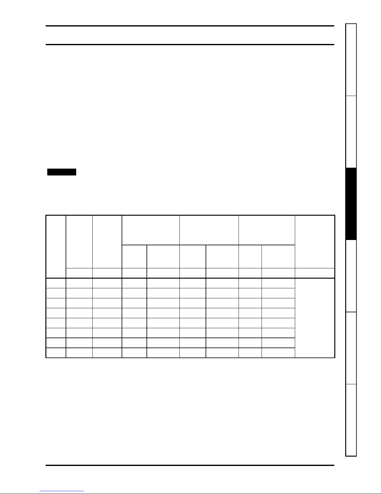
Table 2-1 Low Voltage DC operating range
*Size 4 200V drives have a continuous Low Voltage DC range of 48V to 72V.
The values given in Table 2-1 above are for a typical battery supplied system, this
includes charging of the battery.
If no regen energy is present it is possible to use slightly higher voltage levels.
The AC supply and DC supply must not be connected at the same time, seamless
Drive size
Continuous operating range of a drive
supplied by low voltage DC (Vdc)
148
248-72
348-72
4 48-96*
548-96
648-96
SPMA/D 48-96
Page 7
Unidrive SP Low Voltage DC Installation Guide 7
Issue Number: 1 www.controltechniques.com
Safety Information
Introduction
Product information System design Component data Index
change-over from AC to DC or DC to AC is not possible. See Chapter 4.7 Power circuit
control logic and sequencing on page 24.
For Low Volt age DC operation, as well as the main Low V olt age DC supply the following
external supplies are required.
• For Unidrive SP sizes 1 to 6, a 24Vdc supply must be connected to the +24V
external input on the green control terminal block of the drive (see Chapter
4 System design ). This supplies the control circuitry and may be connected
permanently.
• For Unidrive SP4 SP5 SP6 a 24V external supply needs to be connected to the
24V Low Voltage DC mode enable terminal of the drive. This supply should only be
connected when in Low Voltage DC operation (this supply is in addition to the +24V
external input).(see Chapter 4 System design )
2.3 Operating modes
Low Voltage DC operation can be used in any of the following modes:
1. Open loop mode
• Open loop vector
• Fixed V/F mode (V/Hz)
• Quadratic V/F mode (V/Hz)
2. RFC mode
3. Closed loop vector
4. Servo
2.4 Low Voltage DC speed limitation
When set up for Low V oltage DC operation, the drive can provide rated torque to the motor
at low speeds. The maximum speed that can be achieved whilst operating from this supply
is dependent on the type of motor connected to the drive as described below.
2.4.1 Operation with an induction motor
When operating with an induction motor the drive will effectively start to field weaken at
the point that the output voltage requirement (based on the programmed V/F) reaches
the maximum that the DC bus voltage of the drive can support (about 34V based on a
DC bus of 48V). e.g. The drive would begin to field weaken the motor at around 4Hz for
a 50Hz 400V motor.
The drive may continue to rotate the motor up to base speed. However, even with no
external load (just a bare motor shaft) the motor could stall due to the reduced torque
available whilst so far into field weakening.
Be aware that reduced torque may be experienced in instances where the motor
requires significant volts to magnetise; the reasons for this are listed below.
• The external Low Voltage DC power supply has reached it's maximum supply
voltage to the drive.
• The drive has reached the maximum allowable output voltage available in this mode
of operation.
Low Voltage DC operation CANNOT be used to limit the speed of an induction motor.
The drive can only provide rated torque at low speeds as described above. It is very
important to consider this when operating with an overhauling load such as lift
applications, even with the correct braking resistor selection, the drive may not be able
to maintain control of the load if the drive goes into field weakening.
WARNING
WARNING
Page 8
8 Unidrive SP Low Voltage DC Installation Guide
www.controltechniques.com Issue Number: 1
2.4.2 Operation with a servo motor
The speed of a servo motor is limited based on the Ke (voltage constant) value as
shown in the example below: -
A Unidrive SP with a Low Voltage DC supply of 48V running a 3000rpm unimotor which
has a Ke value of 98V/Krpm.
• Calculate rpm per Volt.
• Calculate drive output voltage.
• From the above calculations the motor speed will be limited to:
When in Low Voltage DC operation the Unidrive SP may NOT be able to limit the speed
of a servo motor with an overhauling load.
If a permanent magnet motor is made to rotate at a high enough speed by an external
torque, the DC bus of the drive and its associated wiring could rise above the lo wer
voltage DC operating level.
WARNING
WARNING
1000rpm 98V⁄ 10.2rpm per volt=
48V 2()⁄ 34V=
10.2 34× 347rpm=
The calculation above gives an estimated value and does not take into account motor
volt drops etc.
NOTE
Page 9
Unidrive SP Low Voltage DC Installation Guide 9
Issue Number: 1 www.controltechniques.com
Safety Information Introduction
Product information
System design Component data Index
3 Product information
3.1 Ratings
3.1.1 Drive output current ratings
For drive output current ratings please refer to the Unidrive SP User Guide.
3.1.2 Low Voltage DC rating
On all but size 1, the applied Low Voltage DC supply level is set by the user in Pr 6.46.
On the size 1 drive this value is non adjustable. The value set by the user will be within
limits as detailed below.
The default setting is 48V for all the drive sizes. The over voltage trip threshold and braking
IGBT turn on voltage are scaled from this value as follows :
• Brake IGBT turn on = 1.325 x Pr 6.46 (V)
• Over voltage trip = 1.45 x Pr 6.46 (V)
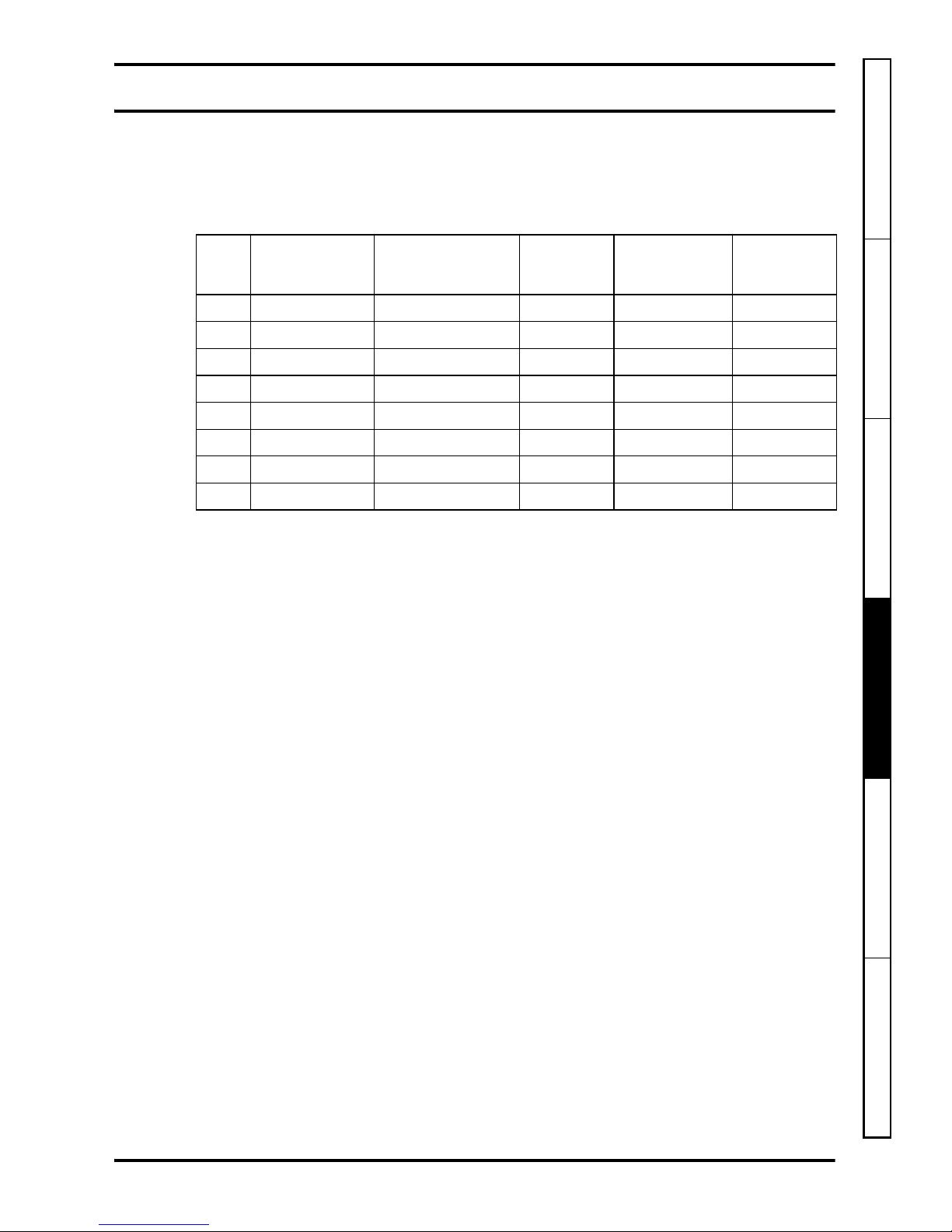
Table 3-1 Low Voltage DC drive rating
Minimum and maximum voltage values include ripple and noise. Ripple and noise levels
must not exceed 5%.
Minimum start up voltage
This is the minimum voltage that is required to initially start up the drive.
Maximum braking IGBT turn on voltage
This is the voltage level that the drive braking IGBT will turn on.
Maximum over voltage trip threshold
This is the voltage level that the drive will trip OV. (Over Voltage).
The maximum supply voltage is governed by the 0V trip level and brake turn-on level.
The drive may be supplied with a greater voltage than the nominal continuous operating
voltage, providing there is suitable headroom between the applied DC voltage and the
brake IGBT turn-on voltage and that regen energy has been taken into account.
NOTE
Drive
size
Under
voltage
trip level
Minimum
start up
voltage
Nominal
continuous
operating voltage
(Pr 6.46)
Maximum braking
IGBT turn on voltage
(Pr 5.05)
Maximum over
voltage trip
threshold
(Pr 5.05)
Required
current rating
of low
voltage DC
supply
200V
drive
variant
400V/575V/
690V drive
variant
200V
drive
variant
400V/575V/
690V drive
variant
200V
drive
variant
400V/575V/
690V drive
variant
VVVVVVVV A
135 40 48 48 63 63 69 69
2 x drive
output current
(heavy duty
current rating)
2 35 40 48 to 72 48 to 72 95 95 104 104
3 35 40 48 to 72 48 to 72 95 95 104 104
4 35 40 48 to 72 48 to 96 95 127 104 139
5 35 40 N/A 48 to 96 N/A 127 N/A 139
6 35 40 N/A 48 to 96 N/A 127 N/A 139
SPMA 35 40 N/A 48 to 96 N/A 127 N/A 139
SPMD 35 40 N/A 48 to 96 N/A 127 N/A 139
Page 10
10 Unidrive SP Low Voltage DC Installation Guide
www.controltechniques.com Issue Number: 1
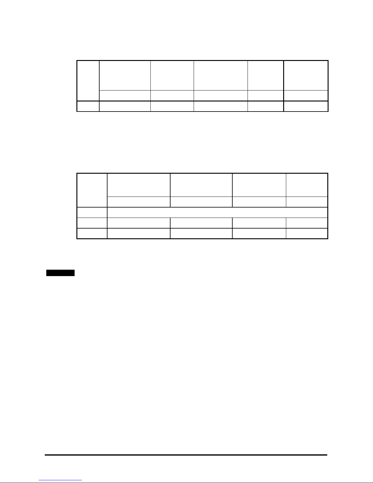
3.1.3 Drive control 24V rating
The table below shows the specification of the control +24V external input terminal that
the user supply should meet.
Table 3-2 Drive control 24V rating
Minimum and maximum voltage values include ripple and noise. Ripple and noise levels
must not exceed 5%.
3.1.4 24V Low Vo ltage DC mode enable rating
Table 3-3 shows the specification of the 24V Low Voltage DC mode enable terminal that
the user supply should meet.
Table 3-3 Low voltage DC mode enable rating
Minimum and maximum voltage values include ripple and noise. Ripple and noise levels
must not exceed 5%.
Drive
size
Maximum
continuous
operating voltage
Minimum
continuous
operating
voltage
Nominal
continuous
Operating voltage
Minimum
start up
voltage
Nominal
current
consumption
VV VVmA
All 30 19.2 24 21.6 500
Drive size
Maximum continuous
operating voltage
Minimum continuous
operating voltage
Nominal
continuous
operating voltage
Nominal
current
consumption
VVVmA
1 to 3 N/A
4 to 6 30 19.2 24 500
SPMA/D 30 19.2 24 500
A common supply can be used for the drive control 24V and 24V Low V oltage DC mode
enable.
NOTE
Page 11
Unidrive SP Low Voltage DC Installation Guide 11
Issue Number: 1 www.controltechniques.com
Safety Information Introduction Product information
System design
Component data Index
4 System design
4.1 Required connections for Low Voltage DC operation
Table 4-1 illustrates what connections and voltage supplies are required for Low Volt age
DC operation.
Table 4-1 Required connections for Low Voltage DC operation
4.2 Low Voltage DC power supply
The supply should meet the requirements set out in section 3.1.2 Low Voltage DC
rating on page 9.
If the Low Voltage DC supply is in the form of a battery and the voltage drops below 36V
a UV trip will occur. A UV trip automatically resets if the DC bus is back within
specification, which means it is possible for the drive to cycle in and out of the trip state
if the drop in voltage only occurs under load.
I.e. The drive is in the 'rdy' condition and the DC bus is within specification. The drive is
given the run command, which enables the output causing current to flow. The DC bus
drops and a UV trip is seen, the drive output is thus disabled. The DC bus then rises
back to the previous level and the UV trip resets. If the run command is still present the
drive output is enabled, which causes current to flow etc.
One of the following should be implemented to prevent this loop from occurring:
1. SM-Applications module not used: A threshold from menu 12 should be used to
monitor the DC bus and trip the drive should it drop below normal operating levels
with a charged battery.
2. SM-Applications module used: A software trap should be added to prevent this loop
from occurring.
Drive
size
Control +24V
external input
24V Low Voltage
DC mode enable
Connection
to 48V
terminal
LVDC supply
+DC/ -DC
External soft
start resistor
1 3 x 33 x
2 3 x 33 x
3 3 x 33 x
4 33x 33
5 33x 33
6 33x 33
SPMA 33x 33
SPMD 33x 33
Page 12
12 Unidrive SP Low Voltage DC Installation Guide
www.controltechniques.com Issue Number: 1
4.3 Low Voltage DC supply types
The DC supply may be connected to ground or left floating. In the event of a contactor
sticking, high voltage would be present at the negative terminal of the drive.
The instructions below ensure user safety in both cases.
4.3.1 Systems with an isolated DC supply
The supply can be floating with respect to ground, although it may have a high
impedance ground to drain leakage currents.
In the event of a fault where AC and DC supplies are connected at the same time a high
current would have no fault path to ground.
In this case:
• The 48V, +DC, -DC terminals of the drive and DC terminals of the Low Voltage DC
source must be protected from user contact.
• The Low Voltage DC supply must be able to withstand mains potential with respect
to ground and be suitable for use in an industrial environment (category 2 supply).
• Cables rated for the voltage of the rectified 3-phase AC supply must be used to
connect the drive to the Low Voltage DC supply.
4.3.2 Systems with a grounded DC supply
The ground connection for the supply must be a high current connection with an I2t
rating greater than the fuses F2a & F2b (see section 5.1 Fusing on page 30).
This is so that in the event of a fault where AC and DC supplies are connected at the
same time a high current will flow to ground and blow the fuses in the Low Voltage DC
path.
• The wiring from the drive to fuses F2a, F2b & F2c must be protected to a voltage
rating equal to or exceeding the rectified 3-phase AC supply voltage (see section
5.1 Fusing on page 30).
• The wiring from the fuse to the supply must be rated correctly for the supply.
4.4 External softstart resistor
When Unidrive SP size 1 to 3 operates from AC or DC there is a built in soft start
resistor to limit the inrush current. However when Unidrive SP size 4 and larger operate
from Low Voltage DC there is no inbuilt soft start resistor and therefore an external soft
start resistor is required between the Low Voltage DC supply and the drive.
In the event of a fault, the 48V, +DC, -DC terminals of the drive and DC terminals of the
Low Voltage DC source (including any wiring in between) could be at a potentially lethal
voltage.
WARNING
If the I2t of the ground connection is not greater than that of the fuses used, then the 48V/
DC terminal and associated wiring could be at a potentially lethal voltage in the event of
a fault.
WARNING
Failure to fit a soft start resistor may damage the drive or/and external components.
NOTE
Page 13
Unidrive SP Low Voltage DC Installation Guide 13
Issue Number: 1 www.controltechniques.com
Safety Information Introduction Product information
System design
Component data Index
4.5 Important considerations and information
• It is possible to run the drive permanently in Low Voltage DC operation.
• The AC supply and DC supply must not be connected at the same time, Seamless
change-over from AC to DC or DC to AC is not possible.
• The drive must be disabled during change over of supplies.
• The DC bus must be forcibly discharged to less than the low voltage braking IGBT
turn on level or less when changing from one supply to another to ensure that the
pre-charge circuits operate correctly. If the load motor is a permanent magnet type,
steps must be taken to ensure that it is stationary or rotating slowly enough that the
emf induced in the windings is less than 25V rms.
• To achieve a reasonably short discharge time an external discharge resistor is
normally required.
• Software should not be used to interlock the supplies, discharge resistor and drive
enable. A software failure could result in hardware damage. Software may however
be used for time delays and selection logic
• All thermal overload devices used must be connected to the supply selection
interlocks, removing AC and DC supplies in the event of a device tripping.
• For Low Voltage DC operation under AC supply loss conditions; all relays and
contactors must be driven from a maintained supply.
• The system design must adhere to one of the system configurations discussed in
section 4.6 System configurations .
•Pr 6.44 indicates which supply the drive is currently operating from:
0 = Normal high voltage supply
1 = Low Voltage DC supply.
Page 14

14 Unidrive SP Low Voltage DC Installation Guide
www.controltechniques.com Issue Number: 1
4.6 System configurations
The following diagrams show different system configurations for a Unidrive SP
operating from a Low Voltage DC supply.
The choice of system configuration depends on the amount of regen energy the DC
supply can absorb.
4.6.1 System configuration 1
This system configuration is suitable for systems were the power supply cannot absorb
any energy from the load through the drive, hence the reason for blocking diode D1
being fitted in series with the DC supply.
Figure 4-1 System configuration 1 circuit diagram for Unidrive SP size 1 to 3
*C1 is only required with Unidrive SP size 1
See Chapter 5 Component data on page 30 for details on components.
F1a
3-phase
AC supply
K1
F2a
F2b
F2c
K2c
K2b
K2a
C1*
Rdis
PS1
D1
K1b K2d
-DC
48V
+DC
L1
L2
L3
48V
DC1/-DC
DC2/+DC
Size 2 and 3
connections
F3
T2
T1
Ovld.1
Aux.1
Control + 24V
external input
Page 15

Unidrive SP Low Voltage DC Installation Guide 15
Issue Number: 1 www.controltechniques.com
Safety Information Introduction Product information
System design
Component data Index
Table 4-2 Key for Figure 4-1
4.6.2 Control implementation for system configuration 1
In order to achieve the required Low Voltage DC operation sequencing as detailed in
section 4.7 Power circuit control logic and sequencing on page 24. The circuitry shown
in Figure 4-1 and Figure 4-2 below are required.
Some of the circuitry shown in Figure 4-2 can be reduced by using SM-Applications, this
is further discussed in section 4.7.2 Control implementation using SM-Applications on
page 26.
Figure 4-2 Control circuitry for system configuration 1
Key Description
Aux.1 Ovld.1 auxillary contact
C1 DC supply capacitor (SP1 only)
D1 Blocking diode to prevent energy from being returned to the LVDC supply
Ovld.1 Thermal overload relay to protect the discharge resistor
F1a 3 phase AC supply fusing
F2a Fuse for LVDC supply feed to drive +DC terminal
F2b Fuse for LVDC supply feed to drive -DC terminal
F2c Fuse for LVDC supply feed to drive 48V terminal
F3 Fuse for drive control 24V external input
K1 Normally open contacts supplying the drive with 3 phase AC when energized
K1b
Normally closed contacts that b ring in t he discharge resistor when the AC supply is
removed
K2a
Normally open contact, which when closed supplies the d rive wit h th e positive fe ed
from the LVDC power supply
K2b
Normally open contact, which when closed supplies th e drive with th e negative feed
from the LVDC power supply
K2c
Normally open contacts whic h when closed supply the 48V terminal of the drive
with LVDC
K2d
Normally closed contacts that br ing in the discharge resist or when the DC supply is
removed
PS1 LVDC power supply
Rdis DC bus discharge resistor
K1
c
K2d
K3a K2e
K3b K1d
K4a
K5a
K2
K1
K5
K4
K3
A
C Supply
select
Enable
input
Drive
enable
Aux.1
Timer Coil, Delay ON
Relay Coil
Normally Open Contacts
Normally Closed Contacts
Key:
Page 16

16 Unidrive SP Low Voltage DC Installation Guide
www.controltechniques.com Issue Number: 1
Figure 4-3 System configuration 1 circuit diagram for Unidrive SP size 4 to 6, SPMA/D
See Chapter 5 Component data on page 30 for details on components.
See section 4.8 External soft start circuit control on page 27 for external soft start circuit
control.
F1a
3-phase
AC supply
K1
F2a
F2b
F2d
K1a
K2b
K2a
Rdis
PS1
D1
K1b K2d
-DC
24V Low voltage DC
mode enable (T51)
L3
L2
L1
0V (T50)
+DC
F3
T1 T2
Rs
41
42
24V
RLY1
Drive
terminals
Aux.1
Ovld.1
F4
Control + 24V
external input
24V
Page 17

Unidrive SP Low Voltage DC Installation Guide 17
Issue Number: 1 www.controltechniques.com
Safety Information Introduction Product information
System design
Component data Index
Table 4-3 Key for Figure 4-3
4.6.3 Control implementation for system configuration 1
In order to achieve the required Low Voltage DC operation sequencing as detailed in
section 4.7 Power circuit control logic and sequencing on page 24. The circuitry shown
in Figure 4-3 and Figure 4-4 below are required.
Some of the circuitry shown in Figure 4-4 can be reduced by using SM-Applications, this
is further discussed in section 4.7.2 Control implementation using SM-Applications on
page 26.
Figure 4-4 Control relays for system configuration 1
Key Description
Aux.1 Ovld.1 auxillary contact
D1 Blocking diode to prevent energy from being returned to the LVDC supply
Ovld.1 Thermal overload relay to protect the discharge resistor
F1a 3 phase AC supply fusing
F2a Fuse for LVDC supply feed to drive +DC terminal
F2b Fuse for LVDC supply feed to drive -DC terminal
F2d Fuse for 24V LVDC mode enable input.
F3 Fuse for drive control 24V external input
F4 Fuse to protect Rs
K1 Normally open contacts supplying the drive with 3 phase AC when energized
K1a Normally closed contacts supplying the 24V LVDC mode enable terminal
K1b
Normally closed contacts that bring in the discharge resistor when the AC supply
is removed
K2a
Normally open contact, which when closed supplies the drive with the positive
feed from the LVDC power supply
K2b
Normally open contact, which when closed supplies the drive with t he negative
feed from the LVDC power supply
K2d
Normally closed contacts that bring in the discharge resistor when the DC supply
is removed
PS1 LVDC power supply
Rly1 Soft start relay that brings the soft start resistor in/out of the DC supply circuit
Rdis DC bus discharge resistor
Rs External soft start resistor
K1
c
K2d
K3a K2e
K3b K1d
K4a
K5a
K2
K1
K5
K4
K3
A
C Supply
select
Enable
input
Drive
enable
Aux.1
Timer Coil, Delay ON
Relay Coil
Normally Open Contacts
Normally Closed Contacts
Key:
Page 18

18 Unidrive SP Low Voltage DC Installation Guide
www.controltechniques.com Issue Number: 1
4.6.4 Preventing over-voltage trips from occurring without the use of a brake
resistor
In the above systems in the case where the load is transferring energy back to the drive
through the motor, the DC bus voltage will rise. If the Low Voltage DC supply is unable
to absorb this energy, the DC bus voltage will continue to rise until the drive trips out on
over-voltage (OU). The drive over-voltage level is dependant on the drive frame size
(See section 3.1.2 Low Voltage DC rating on page 9 for details).
Below are recommendations for preventing this from happening:
1. Lower the setting of the regen current limit (Pr 4.06). This limits how much energy
the drive will absorb from the load.
2. Ensure that the drive is operating in one of the Standard ramp modes (Pr 2.04) and
lower the setting of the Standard ramp voltage (Pr 2.08) to 65.
The changing of the St andard ramp voltage can be automated by the use of the variable
select function, (menu 12) and the programmable logic function, (menu 9).
Reducing the regen current limit can result in the drive losing control of the load under
overhauling load conditions.
WARNING
If the above recommendations are unsuccesfull and the drive still trips OV , then it is likely
that the regen energy is significant enough to require a braking resistor. If this is the case
refer to section 4.6.5 System configuration 2 on page 20.
NOTE
Page 19

Unidrive SP Low Voltage DC Installation Guide 19
Issue Number: 1 www.controltechniques.com
Safety Information Introduction Product information
System design
Component data Index
Page 20

20 Unidrive SP Low Voltage DC Installation Guide
www.controltechniques.com Issue Number: 1
4.6.5 System configuration 2
This configuration is suitable for systems where the drive may be expected to absorb
energy from the load at drive rated current (including overload current if applicable), and
dissipate this energy into a brake resistor. However, further consideration is required
when using a brake resistor in Low Voltage DC mode.
As the DC bus voltage varies the motor power available varies in proportion to the
voltage but the power that may be dissipated in a brake resistor varies with the square
of the voltage. To enable the maximum brake power to match that from the motor in Low
Volt age DC mode, the brake resistor value must be reduced in proportion to the volt age.
The arrangement shown in the circuit below automatically connects the appropriate
brake resistor depending on the supply voltage. Note that the brake resistor thermal
overload devices are also connected to the supply selection interlocks. If either resistor
overheats, then the Low Voltage DC and AC supplies are both tripped off. As shown in
Figure 4-6 Control circuitry for system configuration 2 on page 21
Figure 4-5 System configuration 2 circuit diagram for Unidrive SP size 1 to 3
*C1 is only required with Unidrive SP size 1
See Chapter 5 Component data for details on components.
F2a
F2b
F2c
C1*
Rdis
PS1
D1
K1b K2d
-DC
48V
+DC
48V
DC1/-DC
DC2/+DC
Size 2 and 3
connections
Brake
Brake
F1a
3-phase
AC supply
K1
L1
L2
L3
F3
T2
T1
K2c
K2b
K2a
Aux.1
Ovld.1
R_LVDC
K2f
R_norm
Aux.3
Aux.2
Ovld.3
Ovld.2
Control + 24V
external input
The total brake resistance used in Low Volt age DC mode is the parallel configuration of
R_ LVDC and R_norm.
NOTE
Page 21

Unidrive SP Low Voltage DC Installation Guide 21
Issue Number: 1 www.controltechniques.com
Safety Information Introduction Product information
System design
Component data Index
Table 4-4 Key for Figure 4-5
4.6.6 Control implementation for system configuration 2
In order to achieve the required Low Voltage DC operation sequencing as detailed in
section 4.7 Power circuit control logic and sequencing on page 24. The circuitry shown
in Figure 4-5 and Figure 4-6 below are required.
Some of the circuitry shown in Figure 4-6 can be reduced by using SM-Applications, this
is further discussed in section 4.7.2 Control implementation using SM-Applications on
page 26.
Figure 4-6 Control circuitry for system configuration 2
Key Description
Aux.1 Ovld.1 auxillary contact
Aux.2 Ovld.2 auxillary contact
Aux.3 Ovld.3 auxillary contact
Ovld.3 Thermal overload relay for high voltage braking resistor
Ovld.2 Thermal overload relay for low voltage braking resistor
C1 DC supply capacitor (SP1 only)
D1 Blocking diode to prevent energy from being returned to the LVDC supply
Ovld.1 Thermal overload relay to protect the discharge resistor
F1a 3 phase AC supply fusing
F2a Fuse for LVDC supply feed to drive +DC terminal
F2b Fuse for LVDC supply feed to drive -DC terminal
F2c Fuse for LVDC supply feed to drive 48v terminal
F3 Fuse for drive control 24V external input
K1 Normally open contacts supplying the drive with 3 phase AC when energized
K1b
Normally closed contacts that bring in the discharge resistor when the AC supply is removed
K2a
Normally open contact, which when closed supplie s the drive with the positive fe ed from
the LVDC power supply
K2b
Normally open contact, which when closed supplies the drive with the negative feed
from the LVDC power supply
K2c
Normally open contacts which when closed supply the 48V terminal of the drive with
LVDC
K2d
Normally closed contacts that bring in the discharg e res isto r wh en t he DC supply is removed
K2f Normally open contacts which when closed bring R_LVDC into circuit
PS1 LVDC power supply
Rdis DC bus discharge resistor
R_LVDC Low voltage braking resistor
R_norm High voltage braking resistor
K1c
K2d
K3a K2e
K3b K1d
K4a
K5a
K2
K1
K5
K4
K3
AC Supply
select
Enable
input
Drive
enabl
e
Aux.1
Aux.2 Aux.3
Timer Coil, Delay ON
Relay Coil
Normally Open Contacts
Normally Closed Contacts
Key:
Page 22

22 Unidrive SP Low Voltage DC Installation Guide
www.controltechniques.com Issue Number: 1
Figure 4-7 System configuration 2 circuit diagram for Unidrive SP size 4 to 6, SPMA/D
See Chapter 5 Component data on page 30 for details on components.
See section 4.8 External soft start circuit control on page 27 for external soft start circuit
control.
The total brake resistance used in Low Volt age DC mode is the parallel configuration of
R_ LVDC and R_norm.
F2d
K1a
24V Low voltage DC
mode enable (T51)
0V (T50)
Brake
F3
T1 T2
-DC
+DC
F2a
F2b
K2b
K2a
Rdis
PS1
D1
K1b K2d
Rs
41
42
F1a
3-phase
AC supply
K1
L3
L2
L1
24V
RLY1
Drive
terminals
R_LVDC
K2f
R_norm
Aux.3
Aux.2
Ovld.3
Ovld.2
F4
Aux.1
Ovld.1
Control + 24V
external input
24V
NOTE
Page 23

Unidrive SP Low Voltage DC Installation Guide 23
Issue Number: 1 www.controltechniques.com
Safety Information Introduction Product information
System design
Component data Index
Table 4-5 Key for Figure 4-7
4.6.7 Control implementation for system configuration 2
In order to achieve the required Low Voltage DC operation sequencing as detailed in
section 4.7 Power circuit control logic and sequencing on page 24. The circuitry shown
in Figure 4-7 and Figure 4-8 below are required.
Some of the circuitry shown in Figure 4-8 can be reduced by using SM-Applications, this
is further discussed in section 4.7.2 Control implementation using SM-Applications on
page 26..
Figure 4-8 Control relays for system configuration 2
Key Description
Aux.1 Ovld.1 auxillary contact
Aux.2 Ovld.2 auxillary contact
Aux.3 Ovld.3 auxillary contact
Ovld.3 Thermal overload relay for high voltage braking resisto r
Ovld.2 Thermal overload relay for low voltage braking resist or
D1 Blocking diode to prevent energy from being returned to the LVDC supply
Ovld.1 Thermal overload relay to protect the discharge resistor
F1a 3 phase AC supply fusing
F2a Fuse for LVDC supply feed to drive +DC terminal
F2b Fuse for LVDC supply feed to drive -DC terminal
F2d Fuse for LVDC mode enable input.
F3 Fuse for drive control 24V external input
K1 Normally open contacts supplying the drive with 3 phase AC when energized
K1a Normally closed contacts supplying the LVDC mode enable terminal
K1b
Normally closed contacts th at br in g in the dis char ge resi st or when the AC supp ly is removed
K2a
Normally open contact, which when closed supplies the drive with the positive feed
form the LVDC power supply
K2b
Normally open contact, which when closed supplies the drive with the negative feed
from the LVDC power supply
K2d
Normally closed contact s t hat bri ng in the dischar ge r esis tor when the DC sup ply i s removed
K2f Normally open contacts which when clo se d bring R_LVDC into circuit
PS1 LVDC power supply
Rly1 Softstart relay that brings the softstart resistor in/out of the DC supply circuit
Rdis DC bus discharge resistor
Rs External softstart resistor
R_LVDC Low voltage braking resistor
R_norm High voltage braking resistor
K1c
K2d
K3a K2e
K3b K1d
K4a
K5a
K2
K1
K5
K4
K3
AC Supply
select
Enable
input
Drive
enabl
e
Aux.1
Aux.2 Aux.3
Timer Coil, Delay ON
Relay Coil
Normally Open Contacts
Normally Closed Contacts
Key:
Page 24

24 Unidrive SP Low Voltage DC Installation Guide
www.controltechniques.com Issue Number: 1
4.7 Power circuit control logic and sequencing
Control logic is required to interlock and sequence the contactors set out in section
4.6 System configurations on page 14 to ensure correct operation. This can be
accomplished using relays and timers or an SM-Applications option module.
Figure 4-9 shows the basic logic that is required. The logic provides the following
functions:
• Change-over delay.
• Prevention of both supplies being connected to the drive at the same time.
• The discharge contactor is closed when neither supply is connected.
• Automatic change over of the supply if the AC supply fails, or change-over by switch
selection.
• The drive is disabled when neither supply is connected.
Figure 4-9 Control logic diagram
*Supply loss detection signal could also be the output of a supply selector switch (Low
Voltage DC or nominal AC supply).
AC supply
loss detection*
Drive enable
AC supply
Delay
on t2
Drive enable
Close AC contactor
Close DC contactor
Close discharge contactor
Delay
on t1
Key:
Timer coil, delay ON
Logic AND gate
Logic NOT gate
Logic OR gate
Logic NOR gate
Page 25

Unidrive SP Low Voltage DC Installation Guide 25
Issue Number: 1 www.controltechniques.com
Safety Information Introduction Product information
System design
Component data Index
4.7.1 Control logic sequencing
Figure 4-10 shows the sequencing of the signals which must be accomplished with this
logic.
Figure 4-10 Control logic and sequencing
A
C SUPPLY
SELECT
A
C SUPPLY
CONTACTOR
LOW VOLTAGE
DC SUPPLY
CONTACTOR
DISCHARGE
RESISTOR
DRIVE ENABLE
SIGNAL
AC SUPPLYLOSS, OPEN AC
CONTACTO R& REMOVE ENABLE
CLOSE DISCHARGE RESISTOR
OPEN DISCHARGE RESISTOR
& PROVIDE ENABLE
AC SUPPLYRETURN
REMOVE ENABLE
CLOSE DISCHARGE RESISTOR
OPEN DISCHARGE RESISTOR
CLOSE AC CONTACTOR
& PROVIDE ENABLE
AC SUPPLY SELECTED
DC SUPPLY SELECTED
CONTACTOR CLOSED
CONTACTOR OP EN
CONTACTOR CLOSED
CONTACTOR OP EN
CONTACTOR CLOSED
CONTACTOR OP EN
DRIVE ENABLE PROVIDE
D
DRIVE ENABLE REMOVED
t1 t2
Both delays t1 & t2 should have a mi nimum value of 1s.
CLOSE LOW VOLTAGE CONTACTOR
OPEN LOW VOL TAGE CONTACTOR
Page 26

26 Unidrive SP Low Voltage DC Installation Guide
www.controltechniques.com Issue Number: 1
4.7.2 Control implementation using SM-Applications
Using a second processor simplifies some of the external circuits that are required as
some of the logic and timing can be implemented in software, for example as DPL code.
To use this option for automatic change-over of supplies under mains loss conditions,
the control circuits must be fed from a maintained supply so that when AC power fails
the control circuits stay live.
This circuit below uses the control board and second processor to control the power
contactors K1 & K2. AC/Low V oltage DC supply selection relay K3 (not shown) provides
a supply status signal to the processor. The software then provides time delays and
some interlocks. Note that hardware interlocks are used for supply switching and drive
enable. Software should not be used for the interlocks as a software fault could result in
hardware damage.
Figure 4-11 Control relays with SM-Applications
4.7.3 Sequencing for the SM-Applications option module
Figure 4-12 Sequencing for the SM-Applications option module
The SM-Applications program should be based on the above sequencing, controlling
two of the drive’s digital outputs depending on the state of the AC supply select digital
input.
K1c
K2d
Enable
input
AC Supply
select
Controlboard &
SM-Applications option
Enable
Dig I/P
Dig O/P
Dig O/P
K1
K2
K2e
K1d
Relay Coil
Normally Open Contacts
Normally Closed Contacts
Key:
A
C VOLTAGE
SUPPLY SELECT
A
C SUPPLY
CONTACTOR k1
LVDC SUPPLY
CONTACTOR k2
k1 de-energised
AC SUPPLY SELECTED
CONTACTOR CLOSED
CONTACTOR OPEN
CONTACTOR CLOSED
CONTACTOR OPEN
t1 t2
k2 energised k2 de-energised k1 energised
LVDC SUPPLY SELECTE
D
Both delays t1 & t2 should have a minimum value of 1s.
Page 27

Unidrive SP Low Voltage DC Installation Guide 27
Issue Number: 1 www.controltechniques.com
Safety Information Introduction Product information
System design
Component data Index
4.8 External soft start circuit control
As discussed in section 4.4 External softstart resistor on page 12 an external soft start
resistor is required for Unidrive SP size 4 and larger.
The soft start resistor only needs to be in circuit at certain times as shown in the flow
diagram below.
Figure 4-13 Soft start control circuit sequencing
The above sequencing can be achieved using the drive internal function blocks as
shown in Figure 4-14 on page 28.
Yes
Is the drive powered
from LVDC ?
(Read Pr
6.44
)
Yes
Is the drive in
UV state?
(Read Pr
10.16
)
No
No
Close the drive
relay
(soft start resitor
out of circuit)
Wait 2.5.s
Allow drive
enable
(write 1 to Pr
6.15
)
Page 28

28 Unidrive SP Low Voltage DC Installation Guide
www.controltechniques.com Issue Number: 1
Figure 4-14 Soft start control circuit using drive internal logic
Table 4-6 Parameter set up required for Figure 4-14
The soft start control circuit provides the following functions:
• Opens and closes the external soft start relay contacts, which brings the external
soft start resistor in and out of circuit.
• Prevents the drive from running whilst the soft start resistor is in circuit (when in Low
Voltage DC mode only).
• Ensures that the drive DC bus has reached a voltage level in which the soft start
resistor can be taken out of circuit.
Figure 4-15 Logic function diagram
41
42
6.15
To drive +DC
F4
Rs
From LVDC
supply
PS2
Internal to drive External to drive
Drive
enable
x(-1)
10.16
6.44
2.5s
delay
x(-1)
x(-1)
Normal high voltage
supply = 0
Low voltage DC
supply = 1
Under voltage
active
Healthy = 0
UV trip = 1
Disable = 0
Enable = 1
0V
Parameter Default value Value to be entered
Pr 9.04 Function 1 input 1 source para meter 0.00 10.16
Pr 9.05 Function 1 input 1 invert OFF(0) ON(1)
Pr 9.06 Function 1 input 2 source para meter 0.00 6.44
Pr 9.09 Function-1 delay 0.0 1.5
Pr 8.27 Drive relay source 10.01 9.01
Pr 9.14 Function 2 input 1 source para meter 0.00 9.01
Pr 9.15 Function 2 input 1 invert OFF(0) ON(1)
Pr 9.16 Function 2 input 2 source para meter 0.00 6.44
Pr 9.17 Function 2 input 2 invert OFF(0) ON(1)
Pr 9.20 Function 2 destination parameter 0.00 6.15
Drive enable
Active supply Pr
6.44
Under voltage activePr
10.16
Relay coil
Low voltage DCsupply
Normal high voltage
UV trip
Drive Healthy
Contact closed
Contact open
Enable
Disable
2.5s
Page 29

Unidrive SP Low Voltage DC Installation Guide 29
Issue Number: 1 www.controltechniques.com
Safety Information Introduction Product information
System design
Component data Index
4.9 Running the motor
For information on tuning of the drive for best performance please refer to the Running
the motor and optimization section of the Unidrive SP User Guide.
4.9.1 Autotuning
In order for the drive to obtain the correct motor parameter values, the autotune should
be carried out when operating from a normal high voltage supply and not when in Low
Voltage DC operation. If it is not possible to autotune the drive when operating from a
normal high voltage supply the motor parameters should be obtained from the motor
nameplate and entered into the drive manually.
Ensure that no damage or safety hazard could arise from the motor starting
unexpectedly.
WARNING
The values of the motor parameters affect the protection of the motor.The default
values in the drive should not be relied upon. It is essential that the correct value is
entered in Pr 0.46 Motor rated current. This affects the thermal protection of the motor.
CAUTION
If the keypad mode has been used previously, ensure that the keypad reference has
been set to 0 using the buttons as if the drive is started using the keypad it will
run to the speed defined by the keypad reference (Pr 0.35).
CAUTION
If the intended maximum speed affects the safety of the machinery, additional
independent over-speed protection must be used.
WARNING
Page 30

30 Unidrive SP Low Voltage DC Installation Guide
www.controltechniques.com Issue Number: 1
5 Component data
5.1 Fusing
Table 5-1 Recommended Low Voltage DC supply fuse current ratings (Unidrive
SP size 1 to 3)
Drive
The fuse voltage rating must be suitable for the rectified drive
AC supply voltage, e.g. ≥400Vdc for a SPx20x, ≥750Vdc for a
SPx40x, ≥890Vdc for a SPx50x, and ≥1000Vdc for a SPx60x
F3 (A)
USA fuse
F2a & F2b (A)
European fuse
F2a & F2b (A)
F2c (A)
SP1201 7 8
13A 50Vdc
SP1202 10 10
SP1203 15 16
SP1204 20 20
SP2201 25 25
SP2202 32 35
SP2203 45 50
SP3201 60 63
SP3202 90 100
SP1401 3 4
SP1402 6 6
SP1403 7 8
SP1404 10 10
SP1405 15 16
SP1406 20 20
SP2401 25 25
SP2402 32 35
SP2403 45 50
SP2404 60 63
SP3401 60 63
SP3402 80 80
SP3403 90 100
SP3501 7 8
SP3502 10 10
SP3503 15 16
SP3504 16 20
SP3505 25 25
SP3506 32 35
SP3507 45 50
Page 31

Unidrive SP Low Voltage DC Installation Guide 31
Issue Number: 1 www.controltechniques.com
Safety Information Introduction Product information System design
Component data
Index
Table 5-2 Recommended Low Voltage DC supply fuse current ratings (Unidrive
SP size 4 to 6, SPMA/D)
Drive
The fuse voltage rating must be suitable for the
rectified drive AC supply voltage, e.g. ≥400Vdc for a
SPx20x, ≥750Vdc for a SPx40x, ≥890Vdc for a SPx50x,
and ≥1000Vdc for a SPx60x
F2d F3
USA fuse
F2a & F2b
(A)
European fuse
F2a & F2b (A)
F2c (A)
SP4201 110 125
1
8A 600V AC
fast acting
class CC
type fuse
3A 50Vdc
SP4202 150 160
SP4203 160 175
SP4401 125 125
SP4402 150 160
SP4403 175 200
SP5401 225 250
SP5402 300 315
SP6401 350 350
SP6402 450 450
SPMA 1401 350 350
SPMA 1402 450 450
SPMD 1401 350 350
SPMD 1402 450 450
SPMD 1403 500 500
SPMD 1404 600 630
SP4601 35 40
SP4602 45 50
SP4603 50 50
SP4604 70 80
SP4605 90 100
SP4606 100 100
SP5601 125 125
SP5602 175 200
SP6601 200 200
SP6602 250 250
SPMA 1601 200 200
SPMA 1602 250 250
SPMD 1601 200 200
SPMD 1602 250 250
SPMD 1603 300 300
SPMD 1604 350 355
Page 32

32 Unidrive SP Low Voltage DC Installation Guide
www.controltechniques.com Issue Number: 1
5.2 Discharge resistor and protection
The discharge resistor is required to discharge the DC bus of the drive whilst changing
from one supply to the other.
Table 5-3 Discharge resistor and protection values
*The chosen thermal overload relay must have a class 10 trip characteristic.
Drive
Rdis
(Ω)
Total Power
rating
(W)
Short term (1s)
energy rating
(J)
Thermal overload
relay trip setting
(A)*
SP1201 to SP1202 220 6 3950 0.13
SP1203 to SP1204 100 4 2580 0.25
SP2201 to SP2203 100 6 4030 0.34
SP3201 to SP3202 100 12 8670 0.48
SP4201 to SP4203 100 9 6470 0.48
SP1401 to SP1406 680 17 12180 0.1
SP2401 to SP2404 220 6 3940 0.25
SP3401 to SP3403 220 11 7720 0.32
SP4401 220 9 6660 0.3
SP4402 to SP4403 100 18 13050 0.6
SP5401 to SP5402 100 25 18330 0.79
SP6401 100 33 24510 1.0
SP6402 100 49 36250 1.1
SPMA1401 100 33 24510 1.0
SPMA1402 100 49 36250 1.1
SPMD1401 100 33 24510 1.0
SPMD1402 100 49 36250 1.1
SPMD1403 to SPMD1404 100 62 46560 1.1
SP3501 to SP3507 220 12 8870 0.35
SP5601 to SP5602 100 23 17210 0.8
SP6601 to SP6602 100 35 25850 0.9
SPMA1601 100 35 25850 0.9
SPMA1602 100 35 25850 0.9
SPMD1601 100 35 25850 0.9
SPMD1602 100 35 25850 0.9
SPMD1603 100 37 27230 1.0
SPMD1604 100 37 27230 1.1
High temperatures
The discharge resistor can reach high temperatures. Locate the resistors so that
damage cannot result. Use cable having insulation capable of withstanding high
temperatures.
WARNING
Page 33

Unidrive SP Low Voltage DC Installation Guide 33
Issue Number: 1 www.controltechniques.com
Safety Information Introduction Product information System design
Component data
Index
5.3 Brake resistor
As the DC bus voltage varies the motor power available varies in proportion to the
voltage but the power that may be dissipated in a brake resistor varies with the square
of the voltage. To enable the maximum brake power to match that from the motor in Low
Volt age DC mode, the brake resistor value must be reduced in proportion to the volt age,
therefore a resistor is required in parallel with the normal operation brake resistor.
Please refer to the Unidrive SP User Guide for normal operation brake resistor values.
The table below shows the R_LVDC value resistor that is to be fitted in parallel with the
normal operation brake resistor.
Table 5-4 Brake resistor values (R_LVDC) Unidrive SP 1 to 6
Pr 6.46 48V
60V 72V 84V 96V
Drive
(Ω)
Peak
power
(kW)
Average
power
over 60s
(kW)
(Ω)
Peak
power
(kW)
Average
power
over 60s
(kW)
(Ω)
Peak
power
(kW)
Average
power
over 60s
(kW)
(Ω)
Peak
power
(kW)
Average
power
over 60s
(kW)
(Ω)
Peak
power
(kW)
Average
power
over 60s
(kW)
SP1201
to 1203
7.4 0.55 0.49 N/A N/A N/A N/A N/A N/A N/A N/A N/A N/A N/A N/A
SP1204 4.9 0.83 0.72 N/A N/A N/A N/A N/A N/A N/A N/A N/A N/A N/A N/A
SP2201
to 2203
3.0 1.35 1.35 3.8 1.66 1.66 4.8 1.90 1.90 N/A N/A N/A N/A N/A N/A
SP3201
to 3202
1.1 3.68 3.14 1.5 4.21 3.92 1.8 5.06 4.71 N/A N/A N/A N/A N/A N/A
SP4201
to 4203
0.75 5.62 5.38 1.0 6.32 6.32 1.2 7.58 7.58 N/A N/A N/A N/A N/A N/A
SP1401
to 1404
6.9 0.59 0.36 N/A N/A N/A N/A N/A N/A N/A N/A N/A N/A N/A N/A
SP1405
to 1406
4.5 0.90 0.65 N/A N/A N/A N/A N/A N/A N/A N/A N/A N/A N/A N/A
SP2401
to 2404
1.7 2.38 1.83 2.2 2.87 2.29 2.7 3.37 2.75 N/A N/A N/A N/A N/A N/A
SP3401
to 3403
1.4 2.89 2.69 1.8 3.51 3.36 2.2 4.14 4.04 N/A N/A N/A N/A N/A N/A
SP4401
to 4402
1.0 4.40 4.40 1.2 5.27 5.27 1.5 6.07 6.07 1.7 7.29 7.29 2.0 8.09 8.09
SP4403 0.7 5.86 5.50 0.9 7.02 6.88 1.1 8.27 8.26 1.3 9.53 9.53 1.5 10.79 10.79
SP5401 0.45 8.99 6.73 0.6 10.53 8.41 0.7 13.0 10.09 0.9 13.76 11.77 1.0 16.18 13.45
SP5402 0.45 8.99 8.99 0.6 10.53 10.53 0.7 13.0 13.0 0.7 13.76 13.76 0.8 20.22 18.35
SP6401
to 6402
0.35 11.9 11.90 0.5 12.64 12.64 0.6 15.17 15.17 0.7 17.70 17.70 0.7 23.11 23.11
SP3501
to 3507
1.4 3.00 1.54 1.8 3.51 1.92 2.1 4.33 2.31 N/A N/A N/A N/A N/A N/A
SP4601
to 4606
0.9 4.49 3.83 1.2 5.27 4.79 1.4 6.50 5.75 1.7 7.29 6.71 1.9 8.52 7.67
SP5601
to 5602
0.7 5.95 5.95 0.9 7.02 7.02 1.1 8.27 8.27 1.3 9.53 9.53 1.5 10.79 10.79
SP6601
to 6602
To be confirmed
Page 34

34 Unidrive SP Low Voltage DC Installation Guide
www.controltechniques.com Issue Number: 1
Table 5-5 Brake resistor values (R_LVDC) Unidrive SPMA/D
5.3.1 Brake resistor rating and positioning
When a braking resistor is to be mounted outside the enclosure, ensure that it is
mounted in a ventilated metal housing that will perform the following functions:
• Prevent inadvertent contact with the resistor
• Allow adequate ventilation for the resistor
For high-inertia loads or under continuous braking, the continuous power dissipated in
the braking resistor may be as high as the power rating of the drive. The total energy
dissipated in the braking resistor is dependent on the amount of energy to be extracted
from the load.
The resistor ratings given in Table 5-4 are calculated for maximum braking power for the
particular drive and operating voltage.
In most applications, braking occurs only occasionally . This allows the continuous power
rating of the braking resistor to be much lower. It is essential, though, that the power
rating and energy rating of the braking resistor are sufficient for the most extreme
braking duty that is likely to be encountered.
Optimisation of the braking resistor requires a careful consideration of the braking duty.
Select a value of resistance for the braking resistor that is not less than the specified
minimum resistance. Larger resistance values may give a cost saving, as well as a
safety benefit in the event of a fault in the braking system. Braking capability will then be
reduced, which could cause the drive to trip during braking if the value chosen is too
large.
Pr 6.46 48V
60V 72V 84V 96V
Drive
(Ω)
Peak
power
(kW)
Average
power
over 60s
(kW)
(Ω)
Peak
power
(kW)
Average
power
over 60s
(kW)
(Ω)
Peak
power
(kW)
Average
power
over 60s
(kW)
(Ω)
Peak
power
(kW)
Average
power
over 60s
(kW)
(Ω)
Peak
power
(kW)
Average
power
over 60s
(kW)
SPMA
1401/2
0.35 11.9 11.9 0.5 12.64 12.64 0.6 15.17 15.17 0.7 17.70 17.70 0.7 23.11 23.11
SPMD
1401/2
SPMD
1403
0.23 18 16.5 0.3 21.1 20.5 0.35 26 24.5 0.41 30.25 28.5 0.5 32.5 32.5
SPMD
1404
0.23 18 18 0.3 21.1 21.1 0.35 26 26 0.41 30.5 30.5 0.5 32.5 32.5
SPMA
1601/2
To be confirmed
SPMD
1601/2
SPMD
1603
SPMD
1604
Braking resistor: High temperatures and overload protection
Braking resistors can reach high temperatures. Locate the braking resistors so that
damage cannot result. Use cable having insulation capable of withstanding the high
temperatures. It is essential that the braking resistor is protected against overload
caused by a failure of the brake control. Unless the resistor has in-built protection, a
thermal overload relay should be fitted. In the event of the resistor becoming overloaded,
the protection device must disconnect the AC and Low Voltage DC supply from the drive.
WARNING
Page 35

Unidrive SP Low Voltage DC Installation Guide 35
Issue Number: 1 www.controltechniques.com
Safety Information Introduction Product information System design
Component data
Index
5.3.2 Sizing an appropriate thermal overload relay to protect the brake resistor
The 3 main considerations when calculating the thermal overload relay are as follows:
1. The thermal overload relay with the minimum tripping time must not trip with the
brake current pulse.
2. The peak current through the resistor must not damage the overload relay, this can
be checked by the following equation.
3. The brake resistor capability must be greater than the thermal overload relay with
maximum tripping time.
Worked example
Select a thermal overload relay for an SP1401 operating in normal duty, which will be
braking at 150% of the normal duty rating with a deceleration time of 5 seconds.
Additional data
From Table 5-4 on page 33 the value of R_LVDC will be 6.9Ω.
From section 3.1.2 Low Voltage DC rating on page 9 the LVDC brake turn on voltage
will be:
1.325 x Pr 6.46 (48V) = 63.6V
Normal operation brake turn on voltage = 780V
1. To calculate the thermal overload relay setting (I
set
)
Power from motor at 48V =
Peak current over the braking period =
Nominal motor power Overload %
LVDC brake turn on voltage
Normal operation brake turn on voltage
----------------------------------------------------------------------------------------------------------------
××
1100W 150%
63.6V
780V
---------------
×× 135W==
I
rms
peak()
Peak power at beginning of brake period (W)
Brake resistor value (Ω)
-------------------------------------------------------------------------------------------------------------------------------=
135W
6.9Ω
--------------- -= 4.4A=
Page 36

36 Unidrive SP Low Voltage DC Installation Guide
www.controltechniques.com Issue Number: 1
Use the minimum tripping curves for the chosen manufacturer of thermal overload relay
in order to find the overload factor (F) that will cause the relay to trip after 5 seconds.
The tripping curve below is for a class 10A thermal overload relay.
Figure 5-1 Class 10A thermal overload relay tripping characteristics
From the thermal overload relay-tripping curve above it can be seen that at 5 seconds
the overload factor (F) will be approximately 3.5.
From the above information the thermal overload relay setting (I
set
) will be:
Select a model of thermal overload relay that can be set at 1.26A. (e.g. Telemacanique
LRD-06).
2. Calculate the maximum fault current under fault conditions [I
r
(peak)]
Calculate the maximum current that could flow through the resistor (e.g. due to the
braking transistor becoming short circuit ).
Check that the maximum current under fault conditions is less than 17 times the current
setting of the thermal overload relay.
Overload factor (F) with short circuit =
This is less than 17 times so this thermal overload relay would be suitable.
0.1
1
10
100
1000
10000
110100
overload factor, F
time (s))
thermal overload
mintimecold(s)
thermal overload
average operating
time cold (s)
thermal overload
maxtimecold(s)
I
set
I
rms
peak()
Overload factor(F)
--------------------------------------------------- -=
I
set
4.4
3.5
------- - 1.26A==
I
r
peak()
LVDC brake turn on voltage (V)
R
----------------------------------------------------------------------------------------
63.6V
6.9Ω
--------------- - 9.2A===
I
r
peak )()
I
set
--------------------------
9.2A
1.26A
---------------- 7.3==
If the overload factor (F) is more than 17 times the current setting of the thermal overload
relay , then an in-line fuse would need to be considered. In this case refer to the thermal
overload relay manufacturers recommendations.
NOTE
Page 37

Unidrive SP Low Voltage DC Installation Guide 37
Issue Number: 1 www.controltechniques.com
Safety Information Introduction Product information System design
Component data
Index
3. Check that the chosen resistor can tolerate the overload
Use the maximum time tripping curve to determine the time that corresponds to a factor
(F) of 7.3
From the maximum time tripping curve you get a time of approximately 10 seconds for a
factor (F) of 7.3.
Check that the braking resistor can tolerate 9.2A for 10 seconds.
5.4 External soft start resistor
Table 5-6 Resistor values
5.4.1 External soft start resistor protection
To protect the soft start resistor from becoming damaged in a failure situation a suitable
fuse needs to be fitted in series with the resistor. The fuse must meet the specification
as detailed below.
Table 5-7 Fuse values
Alternative fuse types.
An alternative to the fuses recommended in Table 5-7 can be used providing the fuse
time vs current characteristic lies between the curves shown in the graphs below and
the voltage rating is as per the value shown in Table 5-7.
Drive
Rs
(Ω)
Power
rating
(W)
Energy
rating
(J)
Resistor
part
number
Resistor
combination
SP1202 to SP1204
N/ASP2201 to SP2203
SP3201 to SP3202
SP4201 to SP4203 48 148 1700 1270-2483 1270-2483
SP1401 to SP1406
N/ASP2401 to SP2404
SP3401 to SP3403
SP4401 to SP4403
96 296 3400 1270-2483 2x1270-2483 in series
SP5401 to SP5402
SP6401 to SP6402
SPMA1401 to SPMA1402
SPMD1401 to SPMD1404
SP3501 to SP3507 N/A N/A N/A N/A N/A
SP5601 to SP5602
96 296 3400 1270-2483 2x1270-2483 in series
SP6601 to SP6602
SPMA1601 to SPMA1602
SPMD1601 to SPMD1604
Drive voltage rating
(V)
F4 current
rating
(A)
F4 DC voltage
rating
(V)
Recommended Fuse
type
(Ferraz)
Alternative fuse
type
200 1 500 ATM As set out below
400/575/690 1 1000 A 120X As set out below
Page 38

38 Unidrive SP Low Voltage DC Installation Guide
www.controltechniques.com Issue Number: 1
Figure 5-2 200V drive time vs current fuse characteristic specification
Figure 5-3 400V drive time vs current fuse characteristic specification
0.01
0.1
1
10
100
1000
0.01 0.1 1 10 10
0
current (Arms)
time
(
s
)
0.01
0.1
1
10
100
1000
0.01 0.1 1 10 10
0
current (Arms)
time
(
s
)
Page 39

Unidrive SP Low Voltage DC Installation Guide 39
Issue Number: 1 www.controltechniques.com
Safety Information Introduction Product information System design
Component data
Index
Figure 5-4 575V/690V drive time vs current fuse characteristic specification
5.5 Blocking diode (D1)
The blocking diode D1 is used to prevent energy from being returned into the Low
Voltage DC supply.
Table 5-8 D1 specification
A suitable supplier for the above diode can be Semikron™ with the SKKE isolated base
module diode. The diode must be mounted on a suitable heatsink. See manufacturer
data for heatsink requirements of the device.
5.6 Supply capacitor (C1)
Table 5-9 C1 specification
0.01
0.1
1
10
100
1000
0.01 0.1 1 10 10
0
current (Arms)
time
(
s
)
Drive voltage rating
(V)
Diode type
Working current
(A)
Voltage rating
(V)
200
Standard recovery
3 x drive output
current rating
600
400 1200
575
1500
690
Suitable capacitor
type
Capacitor value
(nF)
Voltage rating
(V)
Metalised polyester 100 ≥250
This capacitor is only required with the Unidrive SP size 1. The capacitor should be
connected directly to the drive terminals.
NOTE
Page 40

40 Unidrive SP Low Voltage DC Installation Guide
www.controltechniques.com Issue Number: 1
5.7 Supplier websites
Resistors
• www.pentagonelectric.co.uk
• www.cressall.com
• www.reo.co.uk
Contactors and thermal overload relays
• www.telemecanique.com
• www.abb.com
• www.omron.co.uk
Fuses
• www.ferrazshawmut.com
• www.bussmann.co.uk
Diodes
• www.semikron.com
• www.ixys.com
This capacitor is only required with the Unidrive SP size 1. The capacitor should be
connected directly to the drive terminals.
NOTE
Page 41

Unidrive SP Low Voltage DC Installation Guide 41
Issue Number: 1 www.controltechniques.com
Safety Information Introduction Product information System design Component data
Index
Index
A
Autotuning ..................................................................................................29
B
Brake resistor .............................................................................................33
C
Cautions .......................................................................................................4
Compliance ..................................................................................................5
D
Discharge resistor and protection ............................................................... 32
Drive control 24V rating ............................................... ...............................10
E
Electrical safety ............................................................................................4
Environmental limits .....................................................................................5
External soft start circuit control .................................................................27
External soft start resistor ...........................................................................37
F
Fusing .............................................................................................30, 31, 37
I
Important considerations and information ..................................................13
L
Low Voltage DC mode enable rating ..........................................................10
Low Voltage DC operating range .................................................................6
Low Voltage DC rating ................................................................................. 9
Low Voltage DC speed limitation .................................................................7
Low Voltage DC Supply types ....................................................................12
O
Operating modes ......................................................... .................................7
P
Parameters - adjusting .................................................................................5
Power circuit control logic and sequencing ................................................24
Pr 6.44 ........................................................................................................13
Pr 6.46 ..........................................................................................................9
Preventing over-voltage trips ......................................................................18
R
Required connections for low voltage DC operation ..................................11
Running the motor .................................. ....................................................29
S
Safety of personnel ......................................................................................4
Secure disable ..............................................................................................4
Supplier websites .......................................................................................40
System configuration ................................................... .............14, 16, 20, 22
Page 42

0471-0060-01
 Loading...