

Page 1
EF
www.controltechniques.com
Advanced User Guide
U
Universal Variable Speed AC
Drive for induction and servo
motors
Part Number: 0471-0002-07
Issue: 7
Page 2

General Information
The manufacturer accepts no liability for any consequences resulting from inappropriate, negligent or incorrect
installation or adjustment of the optional operating parameters of the equipment or from mismatching the variable speed
drive with the motor.
The contents of this guide are believed to be correct at the time of printing. In the interests of a commitment to a policy
of continuous development and improvement, the manufacturer reserves the right to change the specification of the
product or its performance, or the contents of the guide, without notice.
All rights reserved. No parts of this guide may be reproduced or transmitted in any form or by any means, electrical or
mechanical including photocopying, recording or by an information storage or retrieval system, without permission in
writing from the publisher.
Drive software version
This product is supplied with the latest version of software. If this product is to be used in a new or existing system with
other drives, there may be some differences between their software and the software in this product. These differences
may cause this product to function differently. This may also apply to drives returned from a Control Techniques Service
Centre.
The software version of the drive can be checked by looking at Pr 11.29 (or Pr 0.50) and Pr 11.34. The software version
takes the form of zz.yy.xx, where Pr 11.29 displays zz.yy and Pr 11.34 displays xx, i.e. for software version 01.01.00, Pr
11.29 would display 1.01 and Pr 11.34 would display 0.
If there is any doubt, contact a Control Techniques Drive Centre.
Environmental statement
Control Techniques is committed to minimising the environmental impacts of its manufacturing operations and of its
products throughout their life cycle. To this end, we operate an Environmental Management System (EMS) which is
certified to the International Standard ISO 14001. Further information on the EMS, our Environmental Policy and other
relevant information is available on request, or can be found at www.greendrives.com.
The electronic variable-speed drives manufactured by Control Techniques have the potential to save energy and
(through increased machine/process efficiency) reduce raw material consumption and scrap throughout their long
working lifetime. In typical applications, these positive environmental effects far outweigh the negative impacts of product
manufacture and end-of-life disposal.
Nevertheless, when the products eventually reach the end of their useful life, they can very easily be dismantled into their
major component parts for efficient recycling. Many parts snap together and can be separated without the use of tools,
while other parts are secured with conventional screws. Virtually all parts of the product are suitable for recycling.
Product packaging is of good quality and can be re-used. Large products are packed in wooden crates, while smaller
products come in strong cardboard cartons which themselves have a high recycled fibre content. If not re-used, these
containers can be recycled. Polyethylene, used on the protective film and bags for wrapping product, can be recycled in
the same way. Control Techniques' packaging strategy favours easily-recyclable materials of low environmental impact,
and regular reviews identify opportunities for improvement.
When preparing to recycle or dispose of any product or packaging, please observe local legislation and best practice.
Copyright © July 2004 Control Techniques Drives Limited
Issue Number: 7
Software: 01.06.02 onwards
Page 3

Contents
1 Parameter structure.......................................................................................................5
1.1 Menu 0 ...................................................................................................................................................5
1.2 Advanced menus ...................................................................................................................................8
1.3 Solutions Modules .................................................................................................................................8
2 Keypad and display .......................................................................................................9
2.1 Understanding the display .....................................................................................................................9
2.2 Keypad operation ..................................................................................................................................9
2.3 Status mode ........................................................................................................................................10
2.4 Parameter view mode ..........................................................................................................................10
2.5 Edit mode ............................................................................................................................................10
2.6 SM-Keypad Plus advanced operation .................................................................................................11
2.6.1 Browsing filter ............................................................................................................................................................ 11
2.6.2 'Hardware key' feature ............................................................................................................................................... 11
2.7 Parameter access level and security ...................................................................................................11
2.8 Alarm and trip display ..........................................................................................................................13
2.9 Keypad control mode ...........................................................................................................................13
2.10 Drive reset ...........................................................................................................................................13
2.11 Second motor parameters ...................................................................................................................13
2.12 Special display functions .....................................................................................................................13
2.13 SM-Keypad Plus: Menus 41 and 42 ....................................................................................................14
3 Parameter x.00 .............................................................................................................16
3.1 US default differences (1244) ..............................................................................................................16
3.2 SMARTCARD transfers .......................................................................................................................16
3.3 Electronic nameplate transfers ............................................................................................................16
3.4 Display non-default values or destination parameters .........................................................................16
4 Parameter description format.....................................................................................17
4.1 Parameter ranges and variable maximums: ........................................................................................18
4.2 Sources and destinations ....................................................................................................................20
4.3 Update rates ........................................................................................................................................21
4.3.1 Speed reference update rate ..................................................................................................................................... 21
4.3.2 Hard speed reference update rate ............................................................................................................................. 21
4.3.3 Torque reference update rate .................................................................................................................................... 21
5 Advanced parameter descriptions.............................................................................22
5.1 Overview ..............................................................................................................................................22
5.2 Menu 1: Frequency/speed reference ...................................................................................................24
5.3 Menu 2: Ramps ...................................................................................................................................36
5.4 Menu 3: Slave frequency, speed feedback, speed control and regen operation .................................44
5.5 Menu 4: Torque and current control ....................................................................................................80
5.6 Menu 5: Motor control ........................................................................................................................101
5.7 Menu 6: Sequencer and clock ...........................................................................................................122
5.8 Menu 7: Analog I/O ............................................................................................................................135
5.9 Menu 8: Digital I/O .............................................................................................................................145
5.10 Menu 9: Programmable logic, motorised pot and binary sum ...........................................................152
5.11 Menu 10: Status and trips ..................................................................................................................160
5.12 Menu 11: General drive set-up ..........................................................................................................181
5.13 Menu 12: Threshold detectors, variable selectors and brake control function ...................................192
5.14 Menu 13: Position control ..................................................................................................................206
5.15 Menu 14: User PID controller ............................................................................................................218
Unidrive SP Advanced User Guide 3
Issue Number: 7 www.controltechniques.com
Page 4

5.16 Menus 15, 16 and 17: Solutions Module slots .................................................................................. 224
5.16.1 SM-Universal Encoder Plus ..................................................................................................................................... 225
5.16.2 SM-Resolver ............................................................................................................................................................ 248
5.16.3 SM-Encoder Plus ..................................................................................................................................................... 256
5.16.4 SM I/O Plus ............................................................................................................................................................. 263
5.16.5 SM-EZMotion ........................................................................................................................................................... 271
5.16.6 Fieldbus module category parameters .................................................................................................................... 277
5.16.7 SM-Applications ....................................................................................................................................................... 288
5.16.8 SM-SLM ................................................................................................................................................................... 301
5.17 Menu 18: Application menu 1 ........................................................................................................... 314
5.18 Menu 19: Application menu 2 ........................................................................................................... 315
5.19 Menu 20: Application menu 3 ........................................................................................................... 316
5.20 Menu 21: Second motor parameters ................................................................................................ 317
5.21 Menu 22: Additional menu 0 set-up .................................................................................................. 325
6 Macros ....................................................................................................................... 326
6.1 Introduction ....................................................................................................................................... 326
6.1.1 Fundamental differences between Unidrive SP and Unidrive Classic ..................................................................... 328
6.2 Macro 1 - Easy Mode ........................................................................................................................ 329
6.3 Macro 2 - Motorised potentiometer ................................................................................................... 332
6.4 Macro 3 - Preset speeds .................................................................................................................. 336
6.5 Macro 4 - Torque control .................................................................................................................. 340
6.6 Macro 5 - PID control ........................................................................................................................ 344
6.7 Macro 6 - Axis limit control ................................................................................................................ 348
6.8 Macro 7 - Brake control .................................................................................................................... 352
6.9 Macro 8 - Digital Lock ....................................................................................................................... 356
7 Serial communications protocol ............................................................................. 360
7.1 ANSI communications protocol ......................................................................................................... 360
7.2 CT Modbus RTU specification .......................................................................................................... 361
8 Electronic nameplate................................................................................................ 368
8.1 Motor object ...................................................................................................................................... 369
8.2 Performance objects ......................................................................................................................... 370
9 Performance .............................................................................................................. 372
9.1 Digital speed reference ..................................................................................................................... 372
9.2 Analog reference .............................................................................................................................. 372
9.3 Analog outputs .................................................................................................................................. 372
9.4 Digital inputs and outputs ................................................................................................................. 372
9.5 Current feedback .............................................................................................................................. 373
9.6 Bandwidth ......................................................................................................................................... 373
10 Feature look-up table................................................................................................ 374
Index ..........................................................................................................................378
4 Unidrive SP Advanced User Guide
www.controltechniques.com Issue Number: 7
Page 5
Parameter
s
us
structure
Keypad and
display
Parameter x.00
Parameter
description format
Advanced parameter
descriptions
Macros
Serial comms
protocol
Electronic
nameplate
Performance
Feature look-
up table
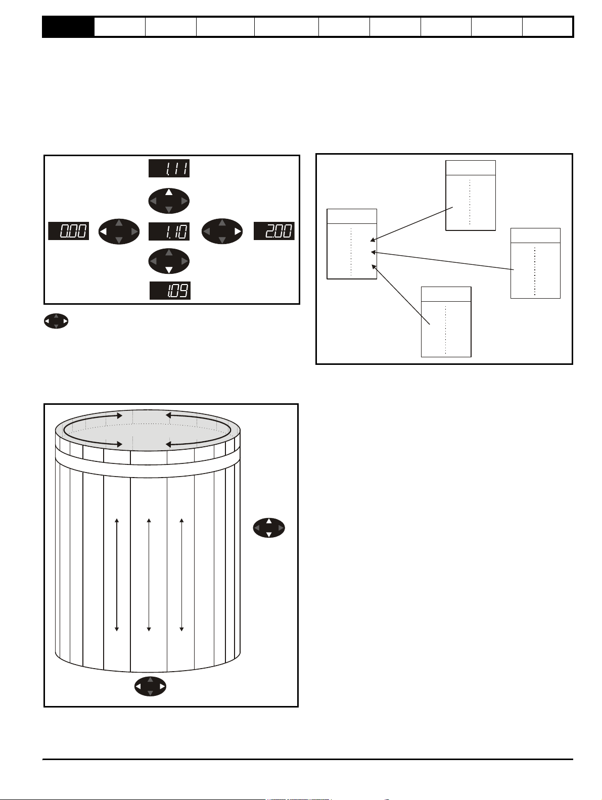
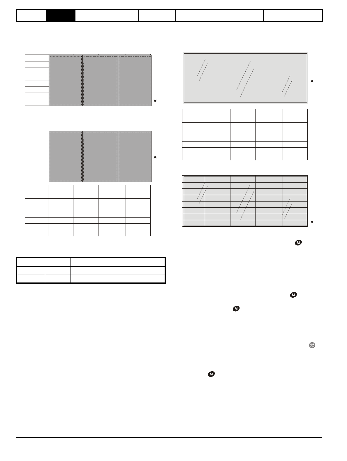
1 Parameter structure
The drive parameter structure consists of menus and parameters.
The drive initially powers up so that only menu 0 can be viewed. The up
and down arrow buttons are used to navigate between parameters and
once level 2 access (L2) has been enabled in Pr 0.49, and the left and
right buttons are used to navigate between menus. For further
information, see section 2.7 Parameter access level and security on
page 11.
Figure 1-1 Parameter navigation
*
* can only be used to move between menus if L2 access has
been enabled (Pr 0.49).
The menus and parameters roll over in both directions; i.e. if the last
parameter is displayed, a further press will cause the display to rollover
and show the first parameter.
When changing between menus the drive remembers which parameter
was last viewed in a particular menu and thus displays that parameter.
Figure 1-2 Menu structure
*
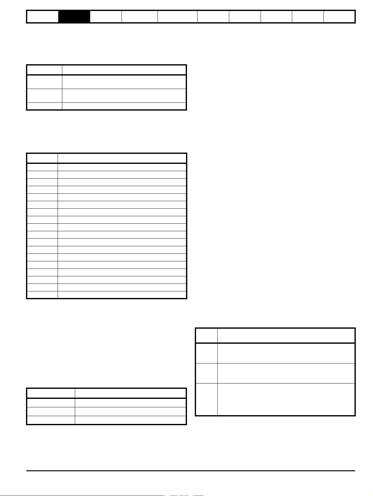
1.1 Menu 0
Menu 0 has up to 31 fixed parameters and 20 programmable parameters
that are defined in menu 11. Menu 0 parameters are copies of advanced
menu parameters, and although these parameters are accessible via
drive 485 comms, they are not accessible to any Solutions Modules. All
menu 0 read/write parameters are saved on exiting the edit mode. Table
1-1 gives the default structure for each drive type setting. Where
alternative parameters are selected with motor map 2 from menu 21
these are shown below the motor map 1 parameters.
Figure 1-3 Menu 0 cloning
Menu 2
150
5
Menu 1
1.14
0
Menu 0
0.04
0.05
0.06
2.21
5
0
150
Menu 4
4.07
M
e
n
u
2
0
M
e
n
u
2
1
Menu 0
....XX.00....
2
1
.
5
0
2
2
2
2
2
2
2
2
2
0.50
1
.
4
9
0.49
1
.
4
8
0.48
1
.
4
7
0.47
1
.
4
6
0.46
1
.
0
5
0.05
1
.
0
4
0.04
1
.
0
3
0.03
1
.
0
2
0.02
1
.
0
1
0.01
Moves between Men
e
M
.
1
.
1
.
1
.
1
.
1
1
1
1
1
1
2
u
n
e
M
1
u
n
0
5
9
4
8
4
7
4
6
4
Moves
between
parameter
5
0
.
4
0
.
3
0
.
2
0
.
1
0
.
Unidrive SP Advanced User Guide 5
Issue Number: 7 www.controltechniques.com
Page 6
Parameter
structure
Keypad and
display
Parameter x.00
Parameter
description format
Advanced parameter
descriptions
Macros
Serial comms
protocol
Electronic
nameplate
Performance
Feature look-
up table
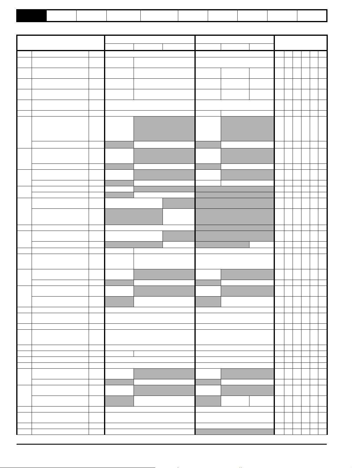
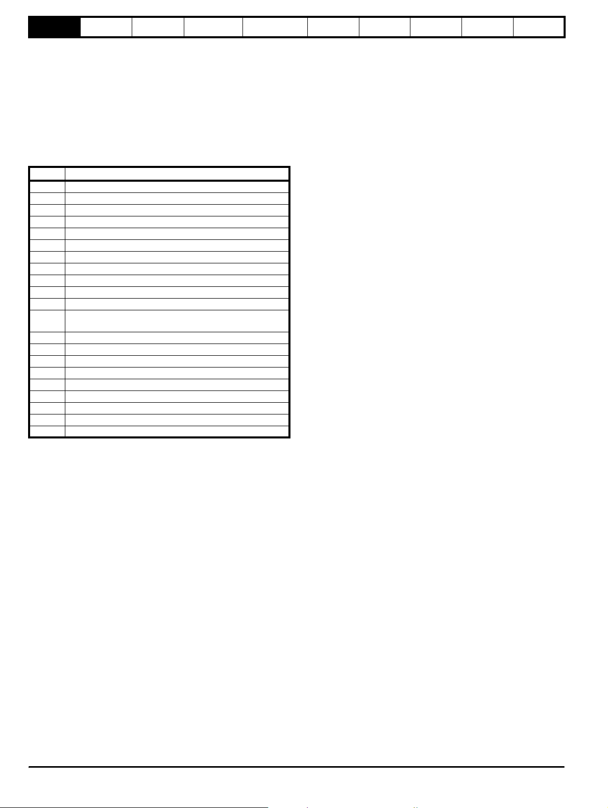
Table 1-1 Menu 0 parameters
Ú) Default(Ö)
Parameter
0.00 xx.00 {x.00} 0 to 32,767 0 RW Uni
0.01 Minimum reference clamp {1.07}
0.02 Maximum reference clamp {1.06} 0 to 3,000.0Hz Speed_limit_max rpm
0.03 Acceleration rate
0.04 Deceleration rate {2.21}
0.05 Reference select {1.14}
0.06 Current limit {4.07} 0 to Current_limit_max % 165.0 175.0 RW Uni RA US
OL> Voltage mode select {5.14}
0.07
CL> Speed controller P gain {3.10}
OL> Voltage boost {5.15}
0.08
CL> Speed controller I gain {3.11}
OL> Dynamic V/F {5.13}
0.09
CL> Speed controller D gain {3.12}
OL> Estimated motor speed {5.04} ±180,000 rpm
0.10
CL> Motor speed {3.02}
OL & VT> Drive output
frequency
0.11
SV> Drive encoder position {3.29}
0.12 Total motor current {4.01} 0 to Drive_current_max A
OL & VT> Motor active
current
0.13
SV> Analog input 1 offset trim {7.07}
0.14 Torque mode selector {4.11} 0 to 1 0 to 4 Speed control mode (0) RW Uni US
0.15 Ramp mode select {2.04}
OL> T28 and T29 autoselection disable
0.16
CL> Ramp enable {2.02}
OL> T29 digital input
destination
0.17
CL> Current demand filter
time constant
0.18 Positive logic select {8.29} OFF (0) or On (1) On (1) RW Bit PT US
0.19 Analog input 2 mode {7.11}
0.20 Analog input 2 destination {7.14}Pr 0.00 to Pr 21.51 Pr 1.37 RW Uni DE PT US
0.21 Analog input 3 mode {7.15}
0.22 Bipolar reference select {1.10} OFF (0) or On (1) OFF (0) RW Bit US
0.23 Jog reference {1.05} 0 to 400.0 Hz 0 to 4000.0 rpm 0.0 RW Uni US
0.24 Pre-set reference 1 {1.21} ±Speed_limit_max rpm 0.0 RW Bi US
0.25 Pre-set reference 2 {1.22} ±Speed_limit_max rpm 0.0 RW Bi US
OL> Pre-set reference 3 {1.23}
0.26
CL> Overspeed threshold {3.08}
OL> Pre-set reference 4 {1.24}
0.27
CL> Drive encoder lines per
revolution
0.28 Keypad fwd/rev key enable {6.13} OFF (0) or On (1) OFF (0) RW Bit US
SMARTCARD parameter
0.29
data
0.30 Parameter cloning {11. 42} nonE (0), rEAd (1), Prog (2), AutO (3), boot (4) nonE (0) RW Txt NC *
0.31 Drive rated voltage {11.33} 200 (0), 400 (1), 575 (2), 690 (3) V
{2.11} 0.0 to 3,200.0
{5.01} ±Speed_freq_max Hz
{4.02} ±Drive_current_max A
{8.39}
{8.26}
{4.12}
{3.34}
{11.36} 0 to 999 0 RO Uni NC PT US
OL VT SV OL VT SV
±3,000.0Hz
s/100Hz
0.0 to 3,200.0
s/100Hz
A1.A2 (0), A1.Pr (1), A2.Pr (2), Pr (3), Pad (4),
Ur_S (0),
Ur (1), Fd (2),
Ur_Auto (3),
Ur_I (4),
SrE (5)
0.0 to 25.0%
of motor rated
voltage
OFF (0) or On
(1)
FASt (0)
Std ( 1)
Std.hV (2)
OFF (0) or On
(1)
Pr 0.00 to
Pr 21.51
0-20 (0), 20-0 (1), 4-20tr (2), 20-4tr (3),
0-20 (0), 20-0 (1), 4-20tr (2), 20-4tr (3),
4-20 (4), 20-4 (5), VOLt (6), th.SC (7),
±Speed_freq_
max Hz/rpm
±Speed_freq_
max Hz/rpm
Range(
±Speed_limit_max rpm
0.000 to 3,200.000
s/1,000rpm
0.000 to 3,200.000
s/1,000rpm
Prc (5)
0.0000 to 6.5535 1/rad s
0.00 to 655.35 1/rad 1.00 RW Uni US
0.00000 to 0.65535 (s) 0.00000 RW Uni US
±Speed_max rpm RO Bi FI NC PT
0 to 65,535
1/2
revolution
±10.000 %
FASt (0)
Std ( 1)
OFF (0) or On (1) On (1) RW Bit US
0.0 to 25.0 ms
4-20 (4), 20-4 (5), VOLt (6)
th (8), th.diSp (9)
0 to 40,000 rpm 0RWUni US
0 to 50,000 1024
16
ths of a
0.0
EUR> 50.0
USA> 60.0
10.0 2.000 0.0200 RW Uni US
Ur_I (4) RW Txt US
-1
EUR> 1,500.0
USA> 1800.0
5.0 2.000 0.0200 RW Uni
A1.A2 (0) RW Txt NC US
3.0 RW Uni US
0 RW Bit US
3,000.0 RW Uni
0.0100 RW Uni US
0.000
Std (1) RW Txt US
0 RW Bit US
Pr 6.31 RW Uni DE PT US
0.0
VOLt (6) RW Txt US
VOLt (6) RW Txt PT US
0.0 RW Bi US
0.0 RW Bi US
4096
RW Bi PT US
RO Bi FI NC PT
RO Bi FI NC PT
RO Uni FI NC PT
RO Uni FI NC PT
RO Bi FI NC PT
RW Bi US
RW Uni US
RW Uni US
RO Txt NC PT
Typ e
US
US
6 Unidrive SP Advanced User Guide
www.controltechniques.com Issue Number: 7
Page 7
Parameter
structure
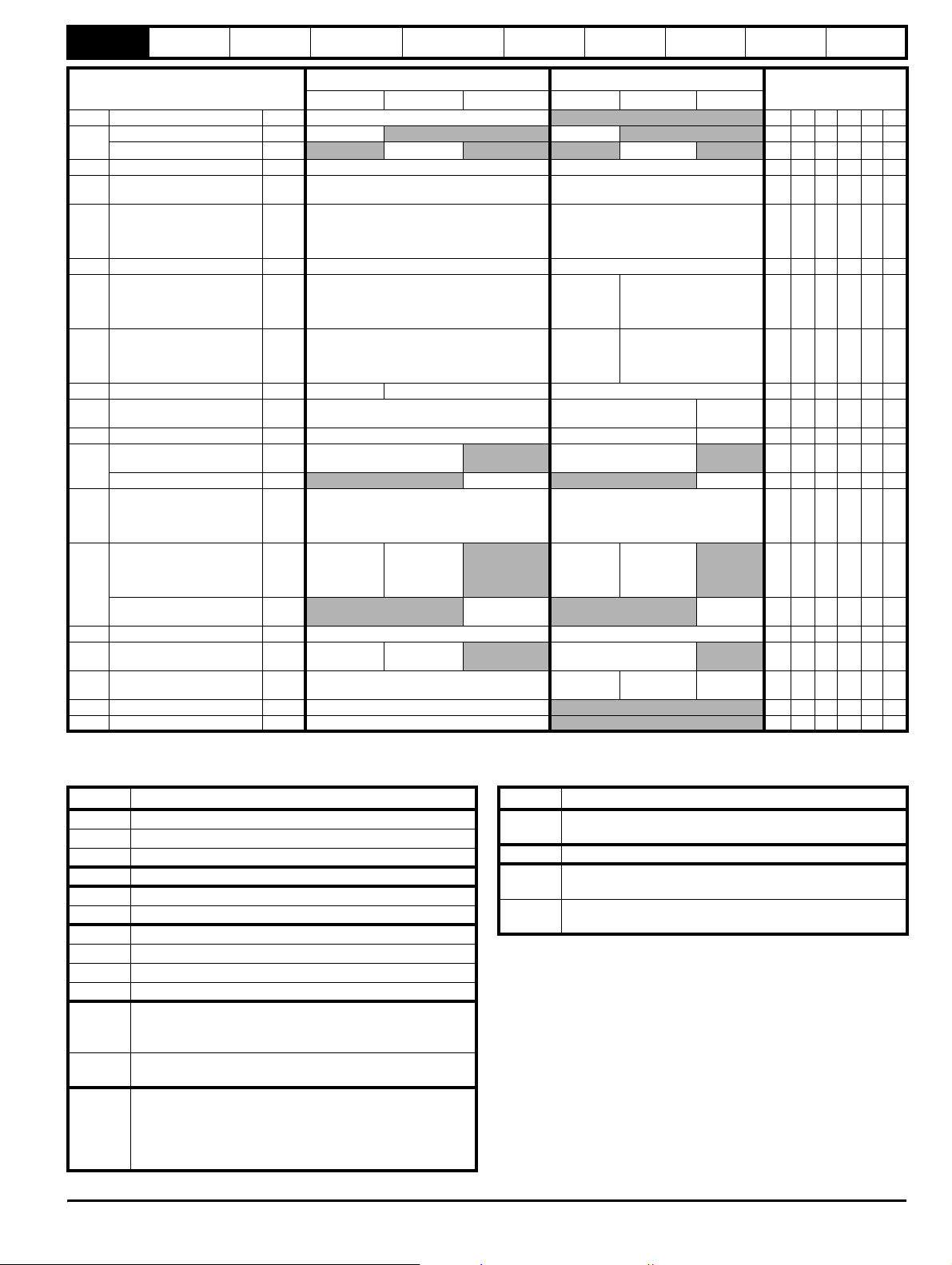
0.32 Drive rated current {11 .32} 0.00 to 9999.99A RO Uni NC PT
0.33
0.34 User security code {11 .30}0 to 999 0RWUniNCPS
0.35 Serial comms mode {11.24 }
0.36 Serial comms baud rate {11.25 }
0.37 Serial comms address {11.23 }0 to 247 1RWUniUS
0.38 Current loop P gain {4.13} 0 to 30,000
0.39 Current loop I gain {4.14} 0 to 30,000
0.40 Autotune {5.12} 0 to 2 0 to 3 0 RW Uni
0.41
0.42 No. of motor poles {5.11} 0 to 60 (Auto to 120 pole) 0 (Auto) 6 POLE (3) RW Txt US
0.43
0.44 Motor rated voltage {5.09} 0 to AC_voltage_set_max V
0.45
0.46 Motor rated current {5.07} 0 to Rated_current_max A Drive rated current [11. 32] RW Uni RA US
0.47 Rated frequency {5.06}
0.48 Operating mode selector {11.3 1}
0.49 Security status {11.44 } L1 (0), L2 (1), Loc (2)
0.50 Software version {11. 29 } 1.00 to 99.99
Keypad and
display
Parameter x.00
Parameter
OL> Catch a spinning motor {6.09}0 to 3
VT> Rated rpm autotune {5.16}
Maximum switching
frequency
OL & VT> Motor rated power
factor
SV> Encoder phase angle {3.25}
OL & VT> Motor rated full
load speed (rpm)
SV> Motor thermal time
constant
{5.18} 3 (0), 4 (1), 6 (2), 8 (3), 12 (4), 16 (5) kHz 3 (0) 6 (2) RW Txt RA US
{5.10} 0.000 to 1.000
{5.09}
{4.15}
Parameter
description format
OL VT SV OL VT SV
300 (0), 600 (1), 1200 (2), 2400 (3), 4800 (4),
9600 (5), 19200 (6), 38400 (7),
57600 (8) Modbus RTU only,
115200 (9) Modbus RTU only
0 to 180,000
rpm
0 to 3,000.0 Hz0 to 1,250.0
OPEn LP (1), CL VECt (2),
SErVO (3), rEgEn (4)
Advanced parameter
descriptions
Ú) Default(Ö)
Range(
0 to 2 0 RW Uni US
AnSI (0)
rtu (1)
0.0 to 359.9° 0.0 RW Uni NC PT
0.00 to
40,000.00 rpm
0.0 to 400.0 20.0 RW Uni US
Hz
Macros
Serial comms
protocol
0 RW Uni US
All voltage
ratings: 20
All voltage
ratings 40
0.850 RW Uni US
200V drive: 230
400V drive: EUR> 400, USA> 460
575V drive: 575
690V drive: 690
EUR> 1,500
USA> 1,800
EUR> 50.0
USA> 60.0
OPEn LP (1) CL VECt (2) SErVO (3) RW Txt NC PT
Electronic
nameplate
Performance
Feature look-
up table
Typ e
rtU (1) RW Txt US
19200 (6) RW Txt US
200V drive: 75
400V drive: 150
575V drive: 180
690V drive: 215
200V drive: 1000
400V drive: 2000
575V drive: 2400
690V drive: 3000
EUR>
1,450.00
USA>
1,770.00
RW Uni US
RW Uni US
RW Uni RA US
RW Uni US
RW Uni US
RW Txt PT US
RO Uni NC PT
* Modes 1 and 2 are not user saved, Modes 0, 3 and 4 are user saved
Key:
Coding Attribute
OL Open loop
VT Closed loop vector
SV Servo
{X.XX} Cloned advanced parameter
RW Read/write: can be written by the user
RO Read only: can only be read by the user
Bit 1 bit parameter: ‘On’ or ‘OFF’ on the display
Coding Attribute
Not cloned: not transferred to or from SMARTCARDs
NC
during cloning.
PT Protected: cannot be used as a destination.
User save: saved in drive EEPROM when the user initiates
US
a parameter save.
Power-down save: automatically saved in drive EEPROM
PS
at power-down.
Bi Bipolar parameter
Uni Unipolar parameter
Txt Text: the parameter uses text strings instead of numbers.
Filtered: some parameters which can have rapidly changing
FI
values are filtered when displayed on the drive keypad for
easy viewing.
Destination: indicates that this parameter can be a
DE
destination parameter.
Rating dependant: this parameter is likely to have different
values and ranges with drives of different voltage and
current ratings. This parameters is not transferred by
RA
SMARTCARDs when the rating of the destination drive is
different from the source drive.
Unidrive SP Advanced User Guide 7
Issue Number: 7 www.controltechniques.com
Page 8
Parameter
structure
Keypad and
display
Parameter x.00
Parameter
description format
Advanced parameter
descriptions
1.2 Advanced menus
The advanced menus consist of groups or parameters appropriate to a
specific function or feature of the drive. These are accessible via the
keypad, drive 485 comms and Solutions Modules. All advanced menu
parameters are only saved by setting Pr x.00 to 1000 and applying a
reset (except parameters shown as power-down saved which are saved
automatically at power-down). The advanced menus are accessible
when the user selects L2 in Pr 11.44 (Pr 0.49 in menu 0). This can be
done even if security is programmed. Pr 11. 44 can be saved in
EEPROM so that either Menu 0 only, or Menu 0 and the advanced
menus are accessible at power-up.
Menu Function
1 Speed reference selection, limits and filters
2Ramps
3 Speed sensing thresholds
4 Current control
5 Motor control
6 Sequencer and clock
7 Analog I/O
8 Digital I/O
9 Programmable logic and motorised pot
10 Drive status and trip information
11 Miscellaneous
Programmable threshold, variable selector and brake control
12
function
13 Position control
14 User PID controller
15 Slot 1 Solutions Module menu
16 Slot 2 Solutions Module menu
17 Slot 3 Solutions Module menu
18 User application menu 1 (saved in drive EEPROM)
19 User application menu 2 (saved in drive EEPROM)
20 User application menu 3 (not saved in drive EEPROM)
21 Second motor map
Macros
Serial comms
protocol
Electronic
nameplate
Performance
Feature look-
up table
1.3 Solutions Modules
Any Solutions Module type is recognised with all drive types in any slots.
The relevant template is used to define menu 15 for the module type
fitted in slot 1, menu 16 for slot 2, and menu 17 for slot 3.
8 Unidrive SP Advanced User Guide
www.controltechniques.com Issue Number: 7
Page 9
Parameter
n
n
structure
Keypad and
display
Parameter x.00
Parameter
description format
Advanced parameter
descriptions
Macros
Serial comms
protocol
Electronic
nameplate
Performance
Feature look-
up table
2 Keypad and display
2.1 Understanding the display
There are two keypads available for the Unidrive SP. The SM-Keypad has an LED display and the SM-Keypad Plus has an LCD display. Both
keypads can be fitted to the drive but the SM-Keypad Plus can also be remotely mounted on an enclosure door.
2.1.1 SM-Keypad
The display consists of two horizontal rows of 7 segment LED displays.
The upper display shows the drive status or the current menu and
parameter number being viewed.
The lower display shows the parameter value or the specific trip type.
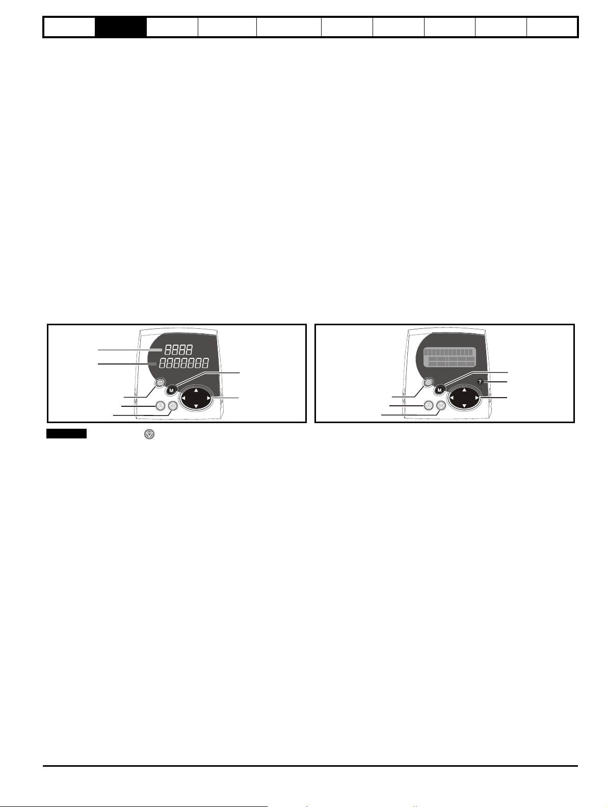
Figure 2-1 SM-Keypad Figure 2-2 SM-Keypad Plus
2.1.2 SM-Keypad Plus
The display consists of three lines of text.
The top line shows the drive status or the current menu and parameter
number being viewed on the left, and the parameter value or the specific
trip type on the right.
The lower two lines show the parameter name or the help text.
Features :
• Parameter names displayed
• Units displayed (Hz, A, rpm, %)
• Parameter help text
• Diagnostics help text
• 5 language support: (English, French, German, Spanish and Italian)
• Displays SM-Applications virtual parameters: Menus 70 to 91
• Hardware key using the SM-Keypad Plus as a key to modify the
drive set-up
• User defined parameter set
• Browsing filter
• Adjustable contrast
Upper display
Lower display
Control buttons
Fwd / Rev (blue) button
Stop/reset (red) button
Start (green) button
NOTE
The red stop button is also used to reset the drive.
Mode (black) butto
Joypad
Control buttons
Fwd / Rev (blue) button
Stop/reset (red) button
Start (green) button
Mode (black) butto
Help button
Joypad
2.2 Keypad operation
2.2.1 Control buttons
The keypad consists of:
1. Joypad - used to navigate the parameter structure and change parameter values.
2. Mode button - used to change between the display modes – parameter view, parameter edit, status.
3. Three control buttons - used to control the drive if keypad mode is selected.
4. Help button (SM-Keypad Plus only) - displays text briefly describing the selected parameter.
The Help button toggles between other display modes and parameter help mode. The up and down functions on the joypad scroll the help text to
allow the whole string to be viewed. The right and left functions on the joypad have no function when help text is being viewed.
The display examples in this section show the SM-Keypad 7 segment LED display. The examples are the same for the SM-Keypad Plus except that
the information displayed on the lower row on the SM-Keypad is displayed on the right hand side of the top row on the SM-Keypad Plus.
The drive parameters are accessed as shown in Figure 2-3.
Unidrive SP Advanced User Guide 9
Issue Number: 7 www.controltechniques.com
Page 10
Parameter
structure
Keypad and
display
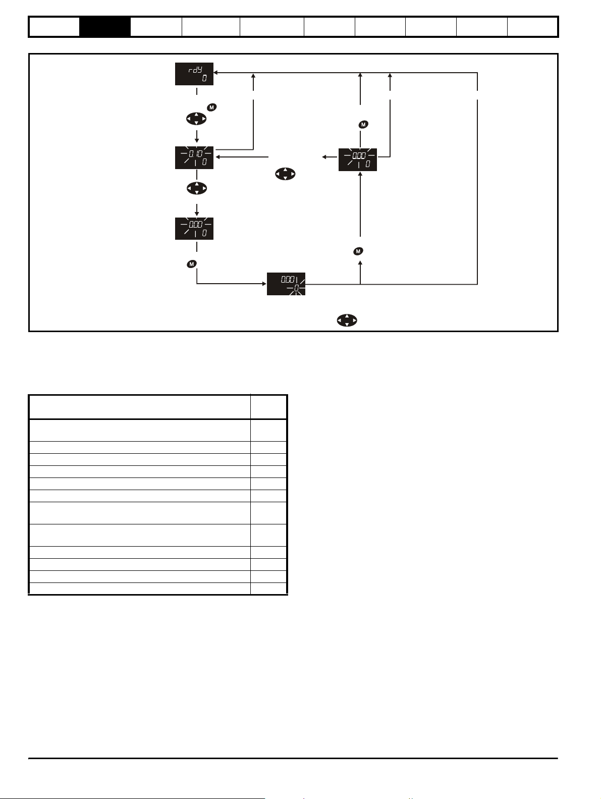
Figure 2-3 Display modes
Status Mode
(Display not flashing)
Parameter x.00
Parameter
description format
Advanced parameter
descriptions
Macros
Serial comms
protocol
Electronic
nameplate
Performance
Feature look-
up table
Timeo ut** Timeo ut**Time out **
When returning
to Parameter
Mode use the
* keys
Edit Mode
(Character to be edited in lower line of display flashing)
Change parameter values
keys to select
another parameter
to change, if
required
Parameter View Mode
(Upper display
flashing)
to select parameter for editing
To enter Parameter
Mode, press key or
Use
To enter Edit Mode,
press key
2.3 Status mode
In status mode the 1st row shows a four letter mnemonic indicating the
status of the drive. The second row show the parameter last viewed or
edited.
State
Auto tune in progress
Upper
row
Auto
tune
Inhibited: enable input is inactive inh
Ready: enable closed, but inverter not active rdY
Stopped: inverter active, but holding zero speed/frequency StoP
Running: inverter active and motor running run
Scanning: trying to synchronise in regen mode SCAN
Mains loss: decelerating to zero in mains loss ride-through or
stop modes
Decelerating: speed/frequency is ramping to zero after a
stop
ACUU
dEC
DC injection: DC injection stop is active dc
Position: position control active during orientation stop POS
Tripped: drive is tripped triP
Active: regen unit is synchronised and the inverter is active act
2.4 Parameter view mode
In this mode the 1st row shows the menu.parameter number and the 2nd
row the parameter value. The 2nd row gives a parameter value range of
-999,999 to 9,999,999 with or without decimal points. (32 bit parameters
can have values outside this range if written by an application module. If
the value is outside this range “-------“is shown and the parameter value
cannot be changed from the keypad.) The Up and Down keys are used
to select the parameter and the Left and Right keys are used to select
the menu. In this mode the Up and Down keys are used to select the
parameter within the selected menu. Holding the Up key will cause the
parameter number to increment until the top of the menu is reached. A
single Up key action when the last parameter in a menu is being
displayed will cause the parameter number to roll over to Pr x.00.
To return to
Status Mode,
press
key
Temporary Parameter
Mode
(Upper display flashing)
*
To exit Edit Mode,
press key
using keys.
Similarly holding the Down key will cause the parameter number to
decrement until Pr x.00 is reached and a single Down key action will
cause the parameter number to roll under to the top of the menu.
Pressing the Up and Down keys simultaneously will select Pr x.00 in the
currently selected menu.
The Left and Right keys are used to select the required menu (provided
the security has been unlocked to allow access to menus other than 0).
Holding the Right key will cause the menu number to increment until the
Menu 21 is reached. A single Right key action when Menu 21 is being
displayed will cause the menu number to roll over to 0. Similarly holding
the Left key will cause the menu number to decrement to 0 and a single
key action will cause the menu number to roll under to Menu 21.
Pressing the Left and Right keys simultaneously will select Menu 0.
The drive remembers the parameter last accessed in each menu such
that when a new menu is entered the last parameter viewed in that menu
will re-appear.
2.5 Edit mode
Up and Down keys are used to increase and decrease parameter values
respectively. If the maximum value of a parameter is greater than 9 and it
is not represented by strings, then the Left and Right keys can be used
to select a digit to adjust. The number of digits which can be
independently selected for adjustment depends on the maximum value
of the parameter. Pressing the Right key when the least significant digit
is selected will cause the most significant digit to be selected, and viceversa if the Left key is pressed when the most significant digit is
selected. When a digit value is not being changed by the Up or Down
keys the selected digit flashes to indicate which one is currently
selected. For string type parameters the whole string flashes when
adjustment is not occurring because there is no digit selection.
During adjustment of a parameter value with the Up or Down keys the
display does not flash, providing the parameter value is in range, such
that the user can see the value being edited without interruption.
Adjustment of a numerical value can be done in one of two ways; firstly
by using the Up and Down keys only, the selected digit remaining the
least significant digit; and secondly by selecting each digit in turn and
adjusting them to the required value. Holding the Up or Down key in the
first method will cause the parameters value to change more rapidly the
longer the key is held, until such time that the parameters maximum or
10 Unidrive SP Advanced User Guide
www.controltechniques.com Issue Number: 7
Page 11
Parameter
structure
Keypad and
display
Parameter x.00
Parameter
description format
Advanced parameter
descriptions
minimum is reached. However with the second method an increasing
rate of change does not take place when adjusting any other digit other
than the least significant digit since a digit can only have one of 10
different values. Holding the Up or Down will cause an auto repeat and
roll over to more significant digits but the rate of change is unaltered. If
the maximum or minimum is exceeded when adjusting any other digit
than the least significant one, the maximum value will flash on the
display to warn the user that the maximum or minimum has been
reached. If the user releases the Up or Down key before the flashing
stops the last in range value will re-appear on the display. If the Up or
Down key is held the display will stop flashing after 3 seconds and the
maximum value will be written to the parameter.
Parameters can be set to 0 by pressing the Up and Down keys
simultaneously.
2.6 SM-Keypad Plus advanced operation
All keypads built after data code N10 have software version 4.02.00
programmed and will support 5 languages (English, French, German,
Spanish and Italian) in addition to the original capability of a user defined
parameter set. This software also gives the user access to two new
menus for SM-Keypad Plus. Menu 40 is for SM-Keypad Plus set up,
menu 41 selects commonly used parameters for quick browsing.
Keypads built prior to N10 will support one user defined extra parameter
set only.
2.6.1 Browsing filter
Pr 40.06 Browsing Filter
The user is able to define their own browsing filter using menu 41. This
allows the user to chose up to 20 parameters for quick browsing in one
vertical menu. (Menu 41 is saved using Pr 40.03).
When in browsing filter mode the first routed parameter will be Pr 41.00,
which will be called 'F00'. The next parameters are the user routed filter
parameters called 'F01' etc.
When the browsing filter has been activated the only parameters
accessible to the user are those specified in the filter. The user scrolls
through the parameters using the up and down joy pad buttons; the left
and right buttons are not used.
NOTE
Pr 71.02 for the SM-Applications in slot 2 is expressed as Pr271.02.
2.6.2 'Hardware key' feature
This feature can be used to prevent unauthorised modification of the
drive parameters via the user interfaces (display or serial comms) on the
front of the drive unless the user has the mating SM-Keypad with the
correct code programmed.
Pr 40.07 Keypad security code
• To lock LCD Keypad internal menus (menus 40 and 41)
• To unlock LCD Keypad internal menus:
Pr 40.09 Hardware key code
Procedure for setting through LCD keypad on RJ45(RS485) port.
• Set up drive security code in Pr 0.34 / Pr 11.30
• Set hardware key code in Pr 40.09 to the same value as the security
• Save the SM-Keypad Plus internal menu by setting Pr 40.03 to save
• Set SM-Keypad Plus internal menu security by writing a code to
• Lock the drive by setting Pr 0.49 / Pr 11.44 to LOC and pressing
The user will have read/write access to the drive parameters but not the
LCD keypad internal menus (Menu 40 and 41) with the specific keypad still
fitted. Any other keypad (SM-Keypad Plus or SM-Keypad without the
correct code programmed ) will provide read only access to all parameters.
Enter code into Pr 40.07.
Exit edit mode - this saves the menu and code.
Enter keypad security code in Pr x.00 (e.g. Pr 40.00).
Press mode (Pr 40.00 and Pr 40.07 will return to zero).
code (Pr 0.34 / Pr 11. 30 becomes value hidden)
(Pr 40.03 will return to idle once save is complete)
Pr 40.07 (Pr 40.09 becomes value hidden)
STOP/RESET (will return to L1)
Macros
Serial comms
protocol
Electronic
nameplate
Performance
Feature look-
up table
Procedure for preventing user access via the RJ45(RS485) port on
the drive.
• Connect PC to RJ45 port and change Pr 11.24 to LCD (this will now
prevent access via a PC), (Timeout error will show on CTsoft, this is
normal)
• Without powering the drive off place the SM-Keypad Plus with
correct hardware key into the RJ45 port and carry out a drive
parameter save.
The user will have read/write access to the drive parameters but not the
SM-Keypad Plus internal menus (menu 40 and 41), and the comms port
will be disabled.
Procedure for resetting hardware key and comms access.
• Unlock the SM-Keypad Plus internal menu security to make Pr 40.09
visible. (See Pr 40.07)
•Zero Pr 40.09
• Unlock drive security by entering the correct code in Pr 0.34 /
Pr 11.30.
• Save the internal SM-Keypad Plus menu (see Pr 40.03 above)
• If the comms port lock is on (i.e.Pr 11 .24 set to LCD) put an SMKeypad onto the front of the drive and turn Pr 11.24 to RTU mode
and carry out a drive save.
The user will now have read/write access to the drive parameters and
the SM-Keypad Plus internal menus (menu 40 and 41).
2.7 Parameter access level and security
The parameter access level determines whether the user has access to
menu 0 only or to all the advanced menus (menus 1 to 21) in addition to
menu 0.
The User Security determines whether the access to the user is read
only or read write.
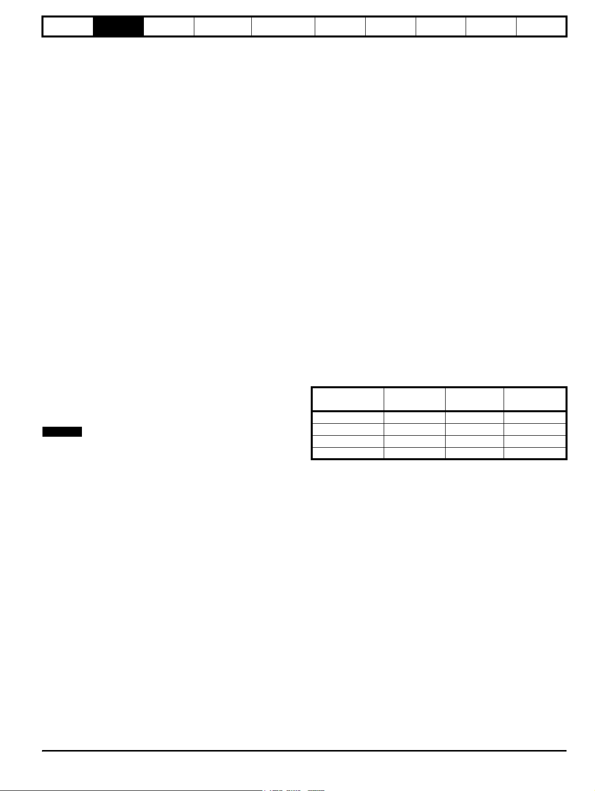
Both the User Security and Parameter Access Level can operate
independently of each other as shown in the table below:
Parameter
Access Level
User Security
Menu 0
status
L1 Open RW Not visible
L1 Closed RO Not visible
L2 Open RW RW
L2 Closed RO RO
RW = Read / write access RO = Read only access
The default settings of the drive are Parameter Access Level L1 and
user Security Open, i.e. read / write access to Menu 0 with the advanced
menus not visible.
Advanced
menus status
Unid rive SP Ad vanced User Guide 11
Issue Number: 7 www.controltechniques.com
Page 12
Parameter
structure
Keypad and
display
Parameter x.00
Parameter
description format
Advanced parameter
descriptions
Macros
Serial comms
protocol
Electronic
nameplate
Performance
Feature look-
up table
2.7.1 Access Level
The access level is set in Pr 0.49 and allows or prevents access to the
advanced menu parameters.
L1 access selected
Pr 0.00
Pr 0.01
Pr 0.02
Pr 0.03
Pr 1.00
Pr 1.01
Pr 1.02
Pr 1.03
- Menu 0 only visible
............
............
............
............
Pr 19.00
Pr 19.01
Pr 19.02
Pr 19.03
Pr 20.00
Pr 20.01
Pr 20.02
Pr 20.03
............
............
Pr 0.49
Pr 0.50
L2 access selected
Pr 0.00
Pr 0.01
Pr 0.02
Pr 0.03
Pr 1.49
Pr 1.50
Pr 1.00
Pr 1.01
Pr 1.02
Pr 1.03
............
............
Pr 19.49
Pr 19.50
- All parameters visible
............
............
............
............
Pr 20.00
Pr 20.01
Pr 20.02
Pr 20.03
Pr 20.49
Pr 20.50
Pr 21.00
Pr 21.01
Pr 21.02
Pr 21.03
............
............
Pr 0.49
Pr 0.50
Pr 1.49
Pr 1.50
............
............
Pr 20.49
Pr 20.50
Pr 21.49
Pr 21.50
2.7.2 Changing the Access Level
The Access Level is determined by the setting of Pr 0.49 as follows:
String Value Effect
L1 0 Access to menu 0 only
L2 1 Access to all menus (menu 0 to menu 21)
The Access Level can be changed through the keypad even if the User
Security has been set.
2.7.3 User Security
The User Security, when set, prevents write access to any of the
parameters (other than Pr. 0.49 Access Level) in any menu.
User security open
Pr 0.00
Pr 0.01
Pr 0.02
Pr 0.03
Pr 0.49
Pr 0.50
Pr 1.00
Pr 1.01
Pr 1.02
Pr 1.03
Pr 1.49
Pr 1.50
User security closed
Pr 0.00
Pr 0.01
Pr 0.02
Pr 0.03
Pr 0.49
Pr 0.50
Pr 1.00
Pr 1.01
Pr 1.02
Pr 1.03
Pr 1.49
Pr 1.50
Setting User Security
Enter a value between 1 and 999 in Pr 0.34 and press the button;
the security code has now been set to this value. In order to activate the
security, the Access level must be set to Loc in Pr 0.49. When the drive
is reset, the security code will have been activated and the drive returns
to Access Level L1. The value of Pr 0.34 will return to 0 in order to hide
the security code. At this point, the only parameter that can be changed
by the user is the Access Level Pr 0.49.
Unlocking User Security
Select a read write parameter to be edited and press the button, the
upper display will now show CodE. Use the arrow buttons to set the
security code and press the button.
With the correct security code entered, the display will revert to the
parameter selected in edit mode.
If an incorrect security code is entered the display will revert to
parameter view mode.
To lock the User Security again, set Pr 0.49 to Loc and press the
reset button.
Disabling User Security.
Unlock the previously set security code as detailed above. Set Pr 0.34 to
0 and press the button. The User Security has now been disabled,
and will not have to be unlocked each time the drive is powered up to
allow read / write access to the parameters.
- All parameters: Read / Write access
............
............
............
............
Pr 20.00
Pr 20.01
Pr 20.02
Pr 20.03
Pr 21.00
Pr 21.01
Pr 21.02
Pr 21.03
............
............
............
............
Pr 20.49
Pr 20.50
Pr 21.49
Pr 21.50
- All parameters: Read Only access
............
............
............
............
Pr 20.00
Pr 20.01
Pr 20.02
Pr 20.03
Pr 21.00
Pr 21.01
Pr 21.02
Pr 21.03
............
............
............
............
Pr 20.49
Pr 20.50
Pr 21.49
Pr 21.50
12 Unidrive SP Advanced User Guide
www.controltechniques.com Issue Number: 7
Page 13
Parameter
structure
Keypad and
display
Parameter x.00
Parameter
description format
Advanced parameter
descriptions
Macros
Serial comms
protocol
Electronic
nameplate
Performance
Feature look-
up table
2.8 Alarm and trip display
In any mode an alarm flashes alternately with the data displayed on the
2nd row when one of the following conditions occur. If action is not taken
to eliminate the all alarms except “Auto tune” the drive may eventually
trip. Warnings are not displayed when a parameter is being edited.
Alarm string Alarm condition
br.rS
OVLd
hot Heatsink or control board alarms are active
When a trip occurs the drive switches to status mode and “trip” is shown
on the 1st row and the trip string flashes on the 2nd row. The read only
parameters listed below are frozen until the trip is cleared. For a list of
the possible trip strings see Pr 10.20. Pressing any of the parameter
keys changes the mode to the parameter view mode. If the trip is HF01
to HF19 then no key action is recognised.
Parameter Description
1.01 Frequency/speed reference
1.02 Frequency/speed reference
1.03 Pre-ramp reference
2.01 Post-ramp reference
3.01 Frequency slaving demand/Final speed ref
3.02 Speed feedback
3.03 Speed error
3.04 Speed controller output
4.01 Current magnitude
4.02 Active current
4.17 Magnetising current
5.01 Output frequency
5.02 Output voltage
5.03 Power
5.04 DC bus voltage
7.01 Analog input 1
7.02 Analog input 2
7.03 Analog input 3
Braking resistor (Pr 10.37 > 75.0% and the braking
IGBT is active)
Motor overload (Pr 4.17 > 75% and the drive output
current > Pr 5.07)
2.9 Keypad control mode
The drive can be controlled from the keypad if Pr 1.14 is set to 4. The
Stop and Run keys automatically become active (the Reverse key may
be optionally enabled with Pr 6.13). The frequency/speed reference is
defined by Pr 1.17. This is a read only parameter that can only be
adjusted in status mode by pressing the Up or Down keys. If keypad
control mode is selected, then pressing the Up or Down keys in status
mode will cause the drive to automatically display the keypad reference
and adjust it in the relevant direction. This can be done whether the drive
is disabled or running. If the Up or Down keys are held the rate of
change of keypad reference increases with time. The units used for to
display the keypad reference for different modes are given below.
Mode Unit
Open loop Hz
Closed loop rpm
Servo rpm
2.10 Drive reset
A drive reset is required to: reset the drive from a trip (except some
“Hfxx” trips which cannot be reset); and other functions as defined in
Section 3. A reset can be performed in four ways:
1. Stop key: If the drive has been set up such that the stop key is not
operative then the key has a drive reset function only. When the stop
function of the stop key is enabled, a reset is initiated while the drive
is running by holding the Run key and then pressing the Stop key.
When the drive is not running the Stop key will always reset the
drive.
2. The drive resets after a 0 to 1 transition of the Drive Reset parameter
(Pr 10.33). A digital input can be programmed to change this
parameter.
3. Serial comms, fieldbus or applications Solutions Module: Drive reset
is triggered by a value of 100 being written to the User trip parameter
(Pr 10.38).
If the drive trips EEF (internal EEPROM error) then it is not possible to
reset the drive using the normal reset methods described above. 1233 or
1244 must be entered into Pr x.00 before the drive can be reset. Default
parameters are loaded after an EEF trip, and so the parameters should
be reprogrammed as required and saved in EEPROM.
If the drive is reset after a trip from any source other than the Stop key,
the drive restarts immediately, if:
1. A non-latching sequencer is used with the enable active and one of
run forward, run reverse or run active
2. A latching sequencer is used if the enable and stop\ are active and
one of run forward, run reverse or run is active.
If the drive is reset with the Stop key the drive does not restart until a not
active to active edge occurs on run forward, run reverse or run.
2.11 Second motor parameters
An alternative set of motor parameters are held in menu 21 which can be
selected by Pr 11.45 . When the alternative parameter set is being used
by the drive the decimal point after the right hand digit in the 1st row is
on.
2.12 Special display functions
The following special display functions are used.
1. If the second motor map is being used the decimal point second
from the right of the first row is on.
2. When parameters are saved to a SMARTCARD the right-most
decimal point on the first row flashes for 2 seconds.
During power up one or more of the following actions may be required.
Each action may take several seconds, and so special display strings
are shown.
Display
string
loading
Action
If a SMARTCARD is present with Pr 11.42 set to boot the
boot
parameters from the card must be transferred to the drive
EEPROM.
If the drive is in auto or boot mode (Pr 11.42 set to 3 or 4) the
card
drive ensures that the data on the card is consistent with the
drive by writing to the card.
It may be necessary for a Solutions Module to transfer
parameter information from the drive. This is only carried out
if the parameter information held by the Solutions Module is
for a different drive software version. The drive allows up to 5
seconds for this process.
Unid rive SP Ad vanced User Guide 13
Issue Number: 7 www.controltechniques.com
Page 14
Parameter
structure
Keypad and
display
Parameter x.00
Parameter
description format
Advanced parameter
descriptions
2.13 SM-Keypad Plus: Menus 41 and 42
2.13.1 Keypad configuration menu
40.00 Zero parameter
The local keypad Zero Parameter works like every other Pr xx.00 in the
Unidrive SP. Entry of a 4-digit number followed by a RESET will allow
change of drive operation mode, save drive parameters, etc.
Three digit numbers are used to unlock keypad security (menus 40 and
41 only). If a keypad security code has been previously entered in
Pr 40.07, then the security code must be entered into Pr xx.00 to unlock
the security. When keypad security is enabled, Pr 40.00 and Pr 41.00
are the only parameters, which can be modified.
40.01 Language select
This parameter allows a change the language (English, custom, French,
German, Spanish or Italian). If the SM-Keypad Plus has a date code
prior top N10, it will only display English and custom. This parameter is
not automatically saved.
40.02 Software version
The software revision of the SM-Keypad Plus firmware is shown here.
Revision 04.01.02 would be displayed as 40102.
40.03 Save configuration to flash
Permits storage and retrieval of local menus 40 and 41 to/from FLASH
memory.
Idle: do nothing
Save: copies menu 40 and 41 to FLASH memory
Restore: restores menu 40 and 41 from FLASH memory
Defaults: sets menu 40 and 41 to factory default values
After completion of a save, restore or default operation, local parameter
Pr 40.03 will revert to "Idle" to give a visual indication that the operation
completed successfully.
Avoid reading or writing to FLASH memory whilst the drive is running.
Macros
Serial comms
protocol
Electronic
nameplate
Performance
Feature look-
up table
During filtered browsing, only the UP and DOWN arrows on the joypad
are used, the LEFT and RIGHT arrows are ignored.
Any parameter on the Unidrive SP, the Keypad Plus or its attached
option modules can be specified in the filtered browsing list in Menu 41.
Any invalid filter parameter specifications, such as a parameter on an
option module that is not fitted, will be ignored.
40.07 Keypad security code
A three-digit code (1 - 999) that, once entered, renders all parameters in
local menus 40 and 41 READ-ONLY. Once keypad security has been
enabled, this parameter is also read-only and its value is displayed as
zero to prevent unauthorized persons from seeing the code.
The only way to remove keypad security once it has been enabled is to
enter the keypad security code into parameter zero of menu 40 or 41.
40.08 Enable string DB upload
Disable: Normal Keypad Plus operation
Enable: Keypad Plus devoted to custom string database upload
only.
Allows upload of the "custom" language from a PC into the SM-Keypad
Plus FLASH memory. When string database upload is enabled, all
normal SM-Keypad Plus operations are stopped and the keypad waits
for communication from the PC (browsing away from this parameter is
not permitted).
A "Keypad String Editor" PC tool is available for use with this feature.
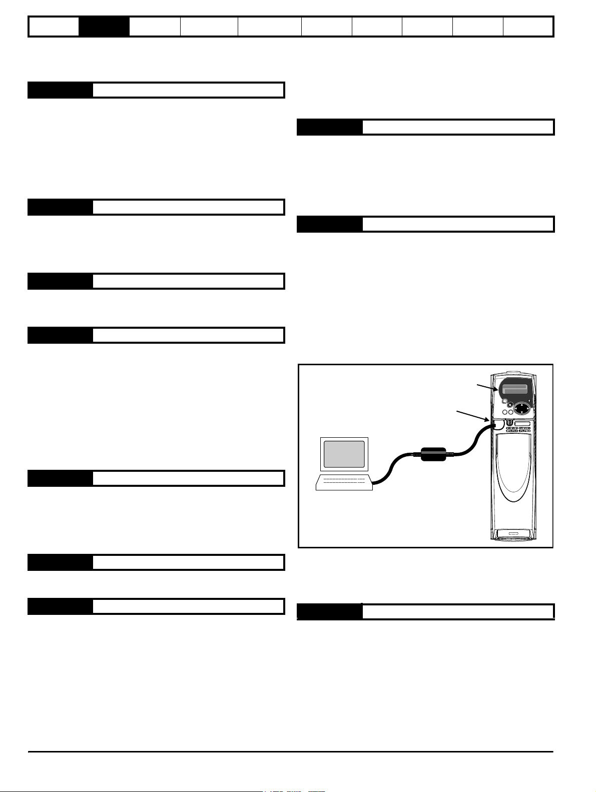
The hardware set-up is shown below. The CT comms cable is used to
connect the PC tool to the drive.
Figure 2-4
SM-Keypad Plus
Drive
Keypad string
485 port
editor tool
40.04 LCD contrast
Changes the contrast of the LCD Display
0: Minimum contrast (5 x 8 character backgrounds are quite
visible)
32: Maximum contrast (5 x 8 character backgrounds are barely
visible)
40.05 SMARTCARD save/restore
This parameter is reserved for future software versions.
40.06 Browsing filter
Selects between normal browsing (all parameters) and filtered browsing.
Normal:Access to all parameters in the drive and installed option
modules
Filter: Access to only those parameters specified in Menu 41 (20
maximum)
When filter browsing is chosen, the SM-Keypad Plus immediately jumps
to the first parameter F00 in the list provided by local menu 41.
Parameter F00 is a standard parameter zero and is fixed. Parameters
F01 through F20 are user-specified. Parameter F21 is a copy of this
parameter (Pr 40.06) and provides an escape from filtered browsing.
CT Comms
cable
COM1
The drive should be set to "inhibit" operational mode before commencing
a upload. This upload operation takes about 15 minutes. When
completed, return local parameter Pr 40.08 to "disable" to resume
normal SM-Keypad Plus operation.
40.09 Hardware key security code
A four-digit code (1 to 9999) that, if equal to the current Unidrive SP
security code, bypasses drive security and allows read / write access to
all drive parameters. Once a hardware key security code has been
entered, this parameter Pr 40.09 becomes read-only and its value is
displayed as zero to prevent unauthorised persons from seeing the
code.
The hardware security code is automatically saved to FLASH memory.
This feature allows an SM-Keypad Plus to be programmed with a
hardware key security code which matches the drive security. The drive
parameters cannot be modified by any other method once the hardware
key security code has been set.
14 Unidrive SP Advanced User Guide
www.controltechniques.com Issue Number: 7
Page 15
Parameter
structure
Keypad and
display
Parameter x.00
Parameter
description format
Advanced parameter
descriptions
This permits service personnel to have exclusive access to drive settings
preventing any possibility of tampering by untrained or unauthorised
personnel.
The only way to remove a hardware key security code is to successfully
disable drive security first by entering the proper security code.
40.10 Keypad serial address
The serial address is by default set to 01. This parameter allows it to be
changed. This only matters when the SM-Keypad Plus is fitted through
the RS-485 port. When the SM-Keypad Plus is plugged directly into the
drive the serial address is forced to 01 in any case.
Making this change is a bit touchy. Plug the SM-Keypad Plus into the
RS-485 port and plug a standard LED Keypad directly into the drive.
Browse to local parameter Pr 40.10 on the SM-Keypad Plus and browse
to Pr 00.37 on the SM-Keypad. Place both parameters into "modify"
mode.
Increment the serial address from 1 to 2 on the SM-Keypad Plus and
then immediately increment the serial address on the SM-Keypad. You
should see both values change. Keep doing this in sequence until the
desired serial address is attained.
40.11 Keypad memory size
Displays the FLASH memory size.
The SM-Keypad Plus has been manufactured with 4 Mbit and 8 Mbit
FLASH memory devices. Keypads fitted with 8 Mbit FLASH devices can
support all six languages (English, custom, French, German, Spanish
and Italian). SM-Keypad Plus units fitted with the smaller 4 Mbit FLASH
devices can only support two languages (English, custom).
Owners of SM-Keypad Plus units built prior to date code N10 should
note that the SM-Keypad Plus String Editor tool can be used to copy any
of the other languages into the "custom" language, giving a bi-lingual
keypad (English and Spanish, for example).
Macros
Serial comms
protocol
Electronic
nameplate
Performance
Feature look-
up table
Some typical filter parameter specifications might be:
0.00 Skip this filter specification
1.23 Drive Pr 1.23 (Preset speed 3)
13.02 Drive Pr 13.02 (Position error)
40.01 Keypad Pr 40.01 (Language select)
SM-Apps in first SM-Application Module installed slot Pr 72.05
72.05
(PLC Register 6)
172.05 SM-Apps in slot 1 Pr 72.05 (PLC register 6)
386.04 SM-Apps in slot 3 Pr 86.04 (Digital output 1)
Any illegal specifications are ignored during browsing. This includes
non-existent parameters or parameters associated with a Solutions
Module that is not fitted.
When filtered browsing is enabled, the menu and parameter display
mmpp is replaced by F00 to F21 (filter parameter numbers). This is a
reminder that filtered browsing is selected.
41.21 Browsing filter
This is a duplicate of Pr 40.06. It is fixed and read-only within Menu 41.
This is to ensure that the filtered browsing list will include an escape
parameter to allow resumption of normal browsing.
2.13.2 Browsing filter menu
41.00 Zero parameter
The local keypad zero parameter works like every other Pr xx.00 in the
Unidrive SP. Entry of a 4-digit number followed by a RESET will allow
change of drive operation mode, save drive parameters, etc.
Three digit numbers are used to unlock keypad security (menus 40 and
41 only). If a keypad security code has been previously entered in
Pr 40.07, then the security code must be entered into Pr xx.00 to unlock
the security. When keypad security is enabled, Pr 40.00 and Pr 41.00
are the only parameters, which can be modified.
41.01 to 41.20 Browsing filter Fnn source
Up to twenty parameters can be selected for the filter-browsing list.
These parameters may be anywhere on the Unidrive SP or on any of the
application modules fitted. Any local SM-Keypad Plus parameter can
also be chosen. Any parameter specification set to zero will be skipped.
Filter parameters are entered in the following format: S M M . P P
S: Slot number (1, 2, 3 or blank)
M M: Menu number
P P: Parameter number
If a slot number is not specified, the SM-Keypad Plus will search for the
first installed SM-Applications module and assign that slot to the
specification.
Unid rive SP Ad vanced User Guide 15
Issue Number: 7 www.controltechniques.com
Page 16

Parameter
structure
Keypad and
display
Parameter
x.00
Parameter
description format
Advanced parameter
descriptions
3 Parameter x.00
Parameter x.00 is available in all menus and has the following functions.
Value Action
1000
1001 Save parameters under all conditions
1070 Reset all Solutions Modules
1233 Load standard defaults
1244 Load US defaults
1253 Change drive mode with standard defaults
1254 Change drive mode with US defaults
1255
1256
3yyy
4yyy
5yyy
6yyy Transfer SMARTCARD data block yyy to the drive
7yyy Erase SMARTCARD data block yyy
8yyy Compare drive parameters with block yyy
9999 Erase SMARTCARD
9888 Set SMARTCARD read-only flag
9777 Clear SMARTCARD read-only flag
110zy
*12000 Display non-default values only
*12001 Display destination parameters only
*These functions do not require a drive reset to become active. All other
functions require a drive reset.
Saving parameters
When parameters are saved all user save (US) parameters are saved to
EEPROM within the drive. Normally Pr x.00 is set to 1000 to save
parameters. When the parameter save is complete Pr x.00 is reset to
zero by the drive. The drive must not be in the under voltage condition
(Pr 10.16 = 0) and must not be using the 48V supply (Pr 6.44 = 0) for this
action to occur. Saving parameters can take between 400ms and
several seconds depending on the number of parameter values that are
different from the values already saved in EEPROM within the drive. If
the power is removed from the drive during a parameter save it is
possible for the EEPROM data to be corrupted giving an EEF failure
when the drive is next powered up. If the drive is operating from the 24V
supply (under voltage condition is active) or from the 48V supply (Pr 6.44
= 1) the power down time is very short. Therefore using Pr x.00 = 1000
to save parameters is a safe method that minimises the risk of corrupting
the data in EEPROM. However, if it is necessary to save parameters
when the drive is in the under voltage condition or when operating from
the 48V supply, Pr x.00 should be set to 1001 to initiate the parameter
save.
Loading defaults
When defaults are loaded the new parameters are automatically saved
to the drive EEPROM in all modes.
SMARTCARD
It should be noted that there could be some conflict between the actions
of Pr x.00 and Pr 11. 42 (Parameter cloning) when the drive is reset. If Pr
11.42 has a value of 1 or 2 and a valid action is required from the value
of Pr x.00 then only the action required by Pr x.00 is performed. Pr x.00
and Pr 11.42 are then reset to zero. If Pr 11.4 2 has a value of 3 or 4 it will
Save parameters when under voltage is not active (Pr
10.16 = 0) and 48V supply is not active (Pr 6.44 = 0).
Change drive mode with standard defaults (excluding
menus 15 to 20)
Change drive mode with US defaults (excluding menus
15 to 20)
Transfer drive EEPROM data to a SMARTCARD block
number yyy
Transfer drive data as difference from defaults to
SMARTCARD block number yyy
Transfer drive ladder program to SMARTCARD block
number yyy
Transfer electronic nameplate parameters to/from drive
from/to encoder
Macros
operate correctly causing parameters to be save to a SMARTCARD
each time a parameter save is performed.
The following differences from standard defaults are available:
Serial comms
protocol
Electronic
nameplate
Performance
Feature look-
up table
3.1 US default differences (1244)
Pr Description Default Modes
Max reference
1.06
clamp
Max reference
1.06
clamp
2.08 Standard ramp volts 775V
5.06 Rated frequency 60.0Hz Open-loop All
5.08 Rated load rpm 1800rpm Open-loop All
5.08 Rated load rpm 1770rpm Closed-loop vector All
5.09 Rated voltage 460V
M2 Max reference
21.01
clamp
M2 Max reference
21.01
clamp
M2 Rated
21.06
frequency
21.09 M2 Rated voltage 460V
60.0Hz Open-loop All
1800rpm Closed-loop vector All
Open-loop, Closed-
loop vector, Servo
Open-loop, Closed-
loop vector, Servo
60.0Hz Open-loop All
1800rpm Closed-loop vector All
60.0Hz Open-loop All
Open-loop, Closed-
loop vector, Servo
Voltage
rating
400V
400V
400V
3.2 SMARTCARD transfers
Drive parameters, set-up macros and internal ladder programs can be
transferred to/from SMARTCARDs. See Pr 11.36 to Pr 11. 40.
3.3 Electronic nameplate transfers
Some encoders using Stegmann 485 or EnDat comms can hold motor
data. The data can be transferred to/from the encoder by writing 110zy
to parameter x.00 and resetting the drive where z is 0 for the drive or 1, 2
or 3 for Solutions Module slots 1, 2 or 3 respectively. See Chapter
8 Electronic nameplate on page 368 for details.
3.4 Display non-default values or destination parameters
If a value of 12000 is written to Pr x.00, then only parameters that are
different from the last defaults loaded and Pr x.00 are displayed. If a
value of 12001 is written to Pr x.00, then only destination parameters are
displayed. This function is provided to aid locating destination clashes if
a dESt trip occurs.
16 Unidrive SP Advanced User Guide
www.controltechniques.com Issue Number: 7
Page 17
Parameter
structure
Keypad and
display
Parameter x.00
Parameter
description format
Advanced parameter
descriptions
Macros
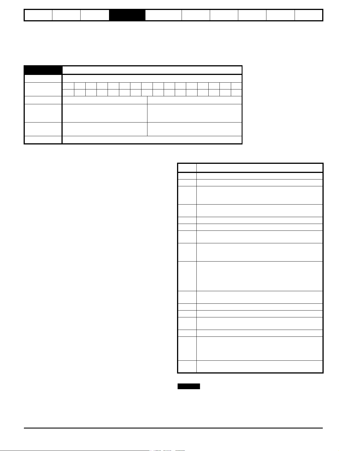
4 Parameter description
format
In the following sections descriptions are given for the advanced
parameter set. With each parameter the following information block is
given.
5.11 Number of motor poles
Drive modes
Coding
Range Open-loop, Closed-loop vector, Servo 0 to 60 (Auto to 120 POLE)
Default
Second motor
parameter
Update rate
Open-loop, Closed-loop vector, Servo
Bit SP FI DE Txt VM DP ND RA NC NV PT US RW BU PS
1111
Open-loop
Closed-loop vector
Servo
Open-loop
Closed-loop vector, Servo
0 (Auto)
0 (Auto)
3 (6 POLE)
Pr 21.18
Background read
Serial comms
protocol
Electronic
nameplate
Performance
Feature look-
up table
The top row gives the menu.parameter number and the parameter
name. The other rows give the following information.
Drive modes
The drive modes are the modes in which this parameter is accessible. If
the parameter is not present the parameter is skipped when accessing
from the keypad. The following types are possible.
Open-loop - with the Unidrive SP hardware and open loop drive mode
selected. The control strategy is V/F mode with fixed boost or open-loop
vector.
Closed-loop vector - with the Unidrive hardware and closed-loop vector
mode selected. The control strategy is rotor flux oriented vector control
with closed-loop current operation for induction motors. The drive can be
operated with or without position feedback.
Servo - with the Unidrive hardware and servo mode selected. The
control strategy is rotor flux oriented vector control with closed-loop
current operation for permanent magnet synchronous motors. The drive
must be operated with position feedback.
Regen - with the Unidrive hardware and regen mode selected. The drive
operates as a PWM rectifier.
Coding
The coding defines the attributes of the parameter as follows:
Coding Attribute
Bit 1 bit parameter
SP Spare: not used
Filtered: some parameters which can have rapidly changing
FI
values are filtered when displayed on the drive keypad for
easy viewing.
Destination: indicates that this parameter can be a
DE
destination parameter.
TE Text: the parameter uses text strings instead of numbers.
VM Variable maximum: the maximum of this parameter can vary.
Decimal place: indicates the number of decimal places used
DP
by this parameter.
No default: when defaults are loaded (except when the drive
ND
is manufactured or on EEPROM failure) this parameter is not
modified.
Rating dependant: this parameter is likely to have different
values and ranges with drives of different voltage and current
ratings. This parameters is not transferred by SMARTCARDs
RA
when the rating of the destination drive is different from the
source drive.
Not cloned: not transferred to or from SMARTCARDs during
NC
cloning.
NV Not visible: not visible on the keypad.
PT Protected: cannot be used as a destination.
User save: saved in drive EEPROM when the user initiates a
US
parameter save.
RW Read/write: can be written by the user.
Bit default one/unsigned: Bit parameters with this flag set to
one have a default of one (all other bit parameters have a
BU
default of zero. Non-bit parameters are unipolar if this flag is
one.
Power-down save: automatically saved in drive EEPROM at
PS
power-down.
NOTE
This guide will show all bit parameters (with the Bit coding), as having a
parameter range of "0 to 1", and a default value of either "0" or "1". This
reflects the value seen through serial communications. The bit
parameters will be displayed on the SM-Keypad (if used) as being "OFF"
or "On" ("OFF"= 0, "On" = 1).
Unid rive SP Ad vanced User Guide 17
Issue Number: 7 www.controltechniques.com
Page 18

Parameter
structure
Keypad and
display
Parameter x.00
Parameter
description format
Advanced parameter
descriptions
4.1 Parameter ranges and variable maximums:
The two values provided define the minimum and maximum values for
the given parameter. In some cases the parameter range is variable and
dependant on either:
• other parameters,
• the drive rating,
• drive mode
• or a combination of these.
The values given in Table 4-1 are the variable maximums used in the
drive.
Table 4-1 Definition of parameter ranges & variable maximums
Maximum Definition
SPEED_FREQ_MAX
[Open-loop 3000.0Hz,
Closed-loop vector and Servo
40000.0rpm]
SPEED_LIMIT_MAX
[40000.0rpm]
SPEED_MAX
[40000.0rpm]
RATED_CURRENT_MAX
[9999.99A]
DRIVE_CURRENT_MAX
[9999.99A]
Maximum speed (closed-loop mode) reference or frequency (open-loop mode) reference
If Pr 1.08 = 0: SPEED_FREQ_MAX = Pr 1.06
If Pr 1.08 = 1: SPEED_FREQ_MAX is Pr 1.06 or – Pr 1.07 whichever is the largest
(If the second motor map is selected Pr 21.01 is used instead of Pr 1.06 and Pr 21.02 instead of Pr 1.07)
Maximum applied to speed reference limits
A maximum limit may be applied to the speed reference to prevent the nominal encoder frequency from
exceeding 400kHz. The maximum is defined by
SPEED_LIMIT_MAX (in rpm) = 400kHz x 60 / ELPR = 2.4x10
40,000 rpm.
ELPR is equivalent encoder lines per revolution and is the number of lines that would be produced by a
quadrature encoder.
Quadrature encoder ELPR = number of lines per revolution
F and D encoder ELPR = number of lines per revolution / 2
Resolver ELPR = resolution / 4
SINCOS encoder ELPR = number of sine waves per revolution
Serial comms encoder ELPR = resolution / 4
This maximum is defined by the device selected with the speed feedback selector (Pr 3.26) and the ELPR set
for the position feedback device.
Maximum speed
This maximum is used for some speed related parameters in menu 3. To allow headroom for overshoot etc.
the maximum speed is twice the maximum speed reference.
SPEED_MAX = 2 x SPEED_FREQ_MAX
Maximum motor rated current
RATED_CURRENT_MAX ≤ 1.36 x Maximum Heavy Duty current rating (Pr 11.3 2)
The rated current can be increased above the rated drive current up to a level not exceeding 1.36 x Maximum
Heavy Duty current rating (Pr 11.3 2). The actual level varies from one drive size to another, refer to Table 4-2.
Maximum drive current
The maximum drive current is the current at the over current trip level and is given by:
DRIVE_CURRENT_MAX = Maximum Heavy Duty current rating (Pr 11.3 2) / 0.45
Macros
Serial comms
protocol
7
Electronic
nameplate
Performance
/ ELPR subject to an absolute maximum of
Feature look-
up table
18 Unidrive SP Advanced User Guide
www.controltechniques.com Issue Number: 7
Page 19
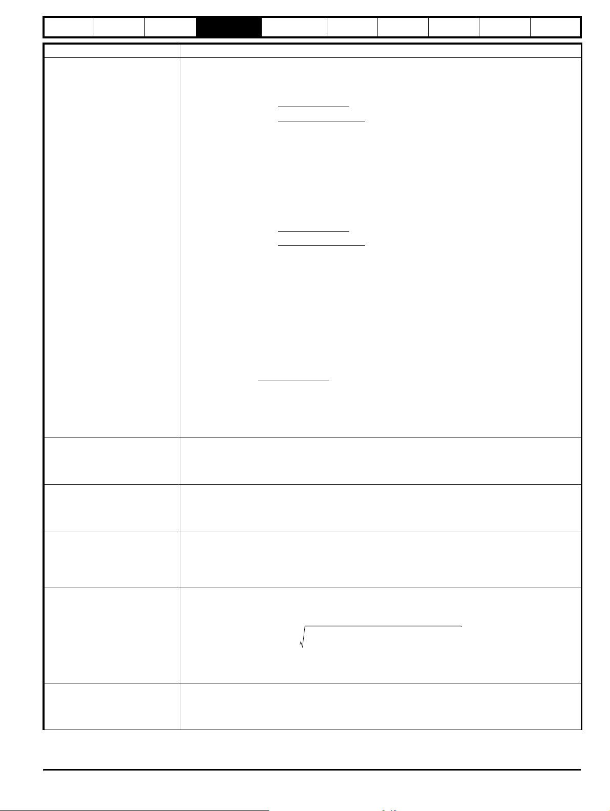
Parameter
√
structure
MOTOR1_CURRENT_LIMIT_MAX
[1000.0%]
Keypad and
display
Maximum Definition
Parameter x.00
2
]
2
]
Serial comms
+ PF2 - 1
+ cos(ϕ
protocol
]
)2 - 1
1
Parameter
description format
Maximum current limit settings for motor map 1
This maximum current limit setting is the maximum applied to the current limit parameters in motor map 1.
Open Loop
Maximum
current limit
Where:
The Maximum current is either (1.5 x Heavy Duty rating) when the rated current set in Pr 5.07 is less than or
equal to the maximum Heavy Duty current rating given by Pr 11.32, otherwise it is (1.1 x Normal Duty rating).
Motor rated current is given by Pr 5.07
PF is motor rated power factor given by Pr 5.10
Closed Loop Vector
Maximum
current limit
Where:
The Maximum current is either (1.75 x Heavy Duty rating) when the rated current set in Pr 5.07 is less than or
equal to the maximum Heavy Duty current rating given by Pr 11.32, otherwise it is (1.1 x Normal Duty rating).
Motor rated current is given by Pr 5.07
ϕ1 = cos-1(PF) - ϕ2. This is measured by the drive during an autotune. See section Closed-loop vector on
page 82 for more information regarding ϕ2.
PF is motor rated power factor given by Pr 5.10
Servo
Maximum
current limit
Advanced parameter
descriptions
Maximum current
[[
PF
√[[
= Motor rated current
=
[
Maximum current
cos(ϕ
Maximum current
Motor rated current
1
]
Macros
)
x 100%
x 100%= Motor rated current
]
x 100%
Electronic
nameplate
Performance
Feature look-
up table
MOTOR2_CURRENT_LIMIT_MAX
[1000.0%]
TORQUE_PROD_CURRENT_MAX
[1000.0%]
USER_CURRENT_MAX
[1000.0%]
REGEN_REACTIVE_MAX
AC_VOLTAGE_SET_MAX
[690V]
Where:
Maximum current is drive rated current (Pr 11.32) x 1.75
Motor rated current is given by Pr 5.07
Maximum current limit settings for motor map 2
This maximum current limit setting is the maximum applied to the current limit parameters in motor map 2.
The formulae for MOTOR2_CURRENT_LIMIT_MAX are the same for MOTOR1_CURRENT_LIMIT_MAX
except that Pr 5.07 is replaced with Pr 21.07 and Pr 5.10 is replaced with Pr 21.10.
Maximum torque producing current
This is used as a maximum for torque and torque producing current parameters. It is
MOTOR1_CURRENT_LIMIT_MAX or MOTOR2_CURRENT_LIMIT_MAX depending on which motor map is
currently active.
Current parameter limit selected by the user
The user can select a maximum for Pr 4.08 (torque reference) and Pr 4.20 (percentage load) to give suitable
scaling for analog I/O with Pr 4.24. This maximum is subject to a limit of MOTOR1_CURRENT_LIMIT_MAX.
or MOTOR2_CURRENT_LIMIT_MAX depending on which motor map is currently active.
USER_CURRENT_MAX = Pr 4.24
Reactive current limit in regen mode
The drive applies a limit to the reactive current reference in regen mode to limit the total current to
DRIVE_CURRENT_MAX.
Rated drive current 1.75×
REGEN_REACTIVE_MAX
Where:
Rated drive current is given in Table 5-3 on page 78.
Regen unit rated current is given by Pr 5.07
Maximum output voltage set-point
Defines the maximum motor voltage that can be selected.
200V drives: 240V, 400V drives: 480V
575V drives: 575V, 690V drives: 690V
------------------------------------------------------------- ------------
Regen unit rated current
2
–
Pr 4.07
2
100%×=
Unid rive SP Ad vanced User Guide 19
Issue Number: 7 www.controltechniques.com
Page 20
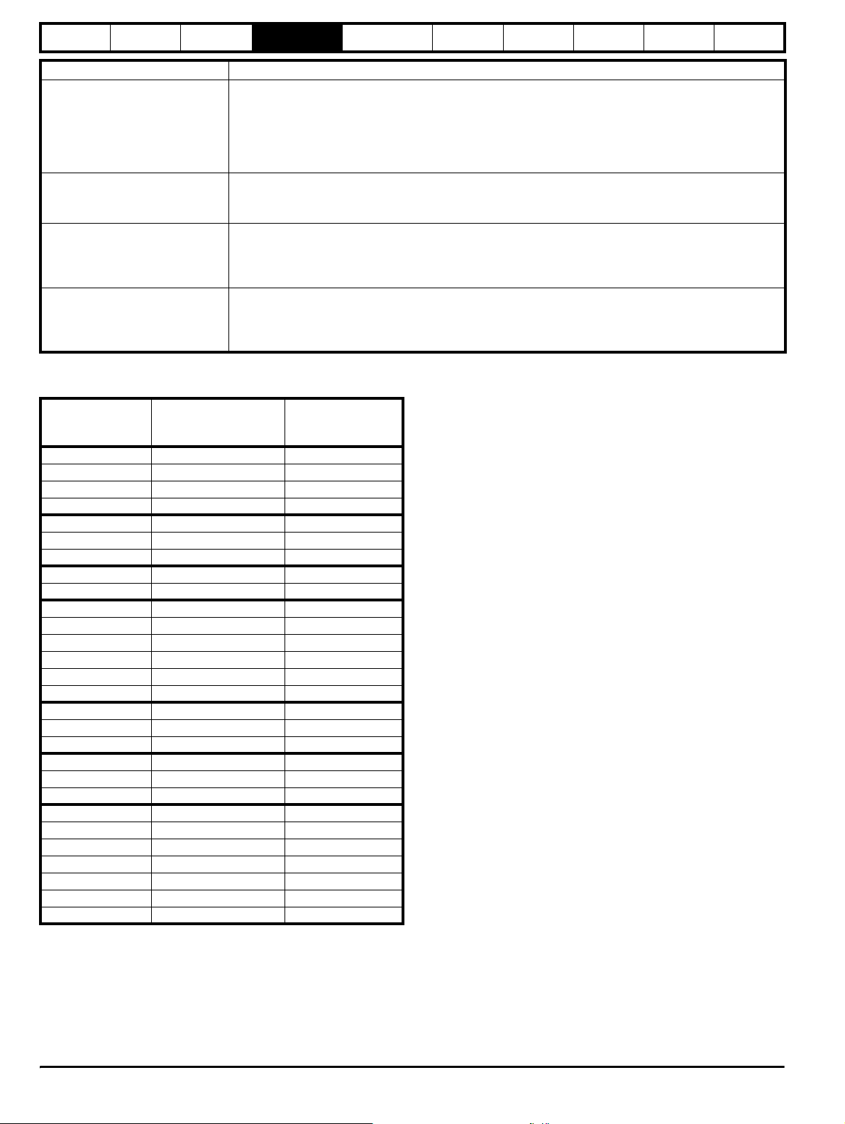
Parameter
structure
Keypad and
display
Parameter x.00
Parameter
description format
Advanced parameter
descriptions
Macros
Serial comms
protocol
Maximum Definition
Maximum AC output voltage
This maximum has been chosen to allow for maximum AC voltage that can be produced by the drive including
AC_VOLTAGE_MAX
[930V]
quasi-square wave operation as follows:
AC_VOLTAGE_MAX = 0.78 x DC_VOLTAGE_MAX
200V drives: 325V, 400V drives: 650V
575V drives: 780V, 690V drives: 930V
DC_VOLTAGE_SET_MAX
[1150V]
Maximum DC voltage set-point
200V rating drive: 0 to 400V, 400V rating drive: 0 to 800V
575V rating drive: 0 to 950V, 690V rating drive: 0 to 1150V
Maximum DC bus voltage
DC_VOLTAGE_MAX
[1190V]
The maximum measurable DC bus voltage.
200V drives: 415V, 400V drives: 830V
575V drives: 995V, 690V drives: 1190V
Maximum power in kW
POWER_MAX
[9999.99kW]
The maximum power has been chosen to allow for the maximum power that can be output by the drive with
maximum AC output voltage, maximum controlled current and unity power factor. Therefore
POWER_MAX = √3 x AC_VOLTAGE_MAX x RATED_CURRENT_MAX x 1.75
The values given in square brackets indicate the absolute maximum value allowed for the variable maximum.
Electronic
nameplate
Performance
Feature look-
up table
Table 4-2 Maximum motor rated current
Model
Maximum Heavy Duty
current rating (Pr
11.32)
Maximum Normal
Duty current rating
SP1201 4.3 5.2
SP1202 5.8 6.8
SP1203 7.5 9.6
SP1204 10.6 11
SP2201 12.6 15.5
SP2202 17 22
SP2203 25 28
SP3201 31 42
SP3202 42 54
SP1401 2.1 2.8
SP1402 3 3.8
SP1403 4.2 5.0
SP1404 5.8 6.9
SP1405 7.6 8.8
SP1406 9.5 11
SP2401 13 15.3
SP2402 16.5 21
SP2403 25 29
SP3401 32 35
SP3402 40 43
SP3403 46 56
SP3501 4.0 5.4
SP3502 5.4 6.1
SP3503 6.1 8.4
SP3504 9.5 11
SP3505 12 16
SP3506 18 22
SP3507 22 27
Default
The default values given are the standard drive defaults which are
loaded after a drive reset with 1233 in Pr x.00.
Second motor parameter
Some parameters have an equivalent second motor value that can be
used as an alternative when the second motor is selected with Pr 11 .45.
Menu 21 contains all the second motor parameters. In this menu the
parameter specifications include the location of the normal motor
parameter which is being duplicated.
Update rate
Defines the rate at which the parameter data is written by the drive
(write) or read and acted upon by the drive (read). Where background
update rate is specified, the update time depends on the drive processor
load. Generally the update time is between 2ms and 30ms, however, the
update time is significantly extended when loading defaults, changing
drive mode, transferring data to/from a SMARTCARD, or transferring
blocks of parameters or large CMP data blocks to/from the drive (not a
Solutions Module) via the drive serial comms port.
4.2 Sources and destinations
Sources
Some functions have source parameters, i.e. drive outputs, PID
controller etc. The source parameter range is Pr 0.00 to Pr 21.51.
1. If the source parameter does not exist the input is taken as zero.
2. The input is given by (source value x 100%) / source parameter
maximum.
Destinations
Some functions have destination parameters, i.e. drive inputs, etc. The
destination parameter range is Pr 0.00 to Pr 21.51.
1. If the destination parameter does not exist then the output value has
no effect.
2. If the destination parameter is protected then the output value has
no effect.
3. If the function output is a bit value (i.e. a digital input) the destination
value is either 0 or 1 depending on the state of the function output. If
the function output is not a bit value (i.e. analog input) the
destination value is given by (function output x destination
parameter maximum) / 100%. Pr 1.36 and Pr 1.37 are a special
case. The scaling shown in the description of Pr 1.08 is used when
any non-bit type quantity is routed to these parameters.
4. If more than one destination selector is routed to the same
destination, the value of the destination parameter is undefined. The
drive checks for this condition where the destinations are defined in
any menu except menus 15 to 17. If a conflict occurs a dESt trip
occurs that cannot be reset until the conflict is resolved.
Sources and destinations
1. Bit and non-bit parameters may be connected to each other as
sources or destinations. The maximum for bit parameters is taken as
one.
2. All new source and destination routing only changes to new set-up
locations when the drive is reset.
20 Unidrive SP Advanced User Guide
www.controltechniques.com Issue Number: 7
Page 21
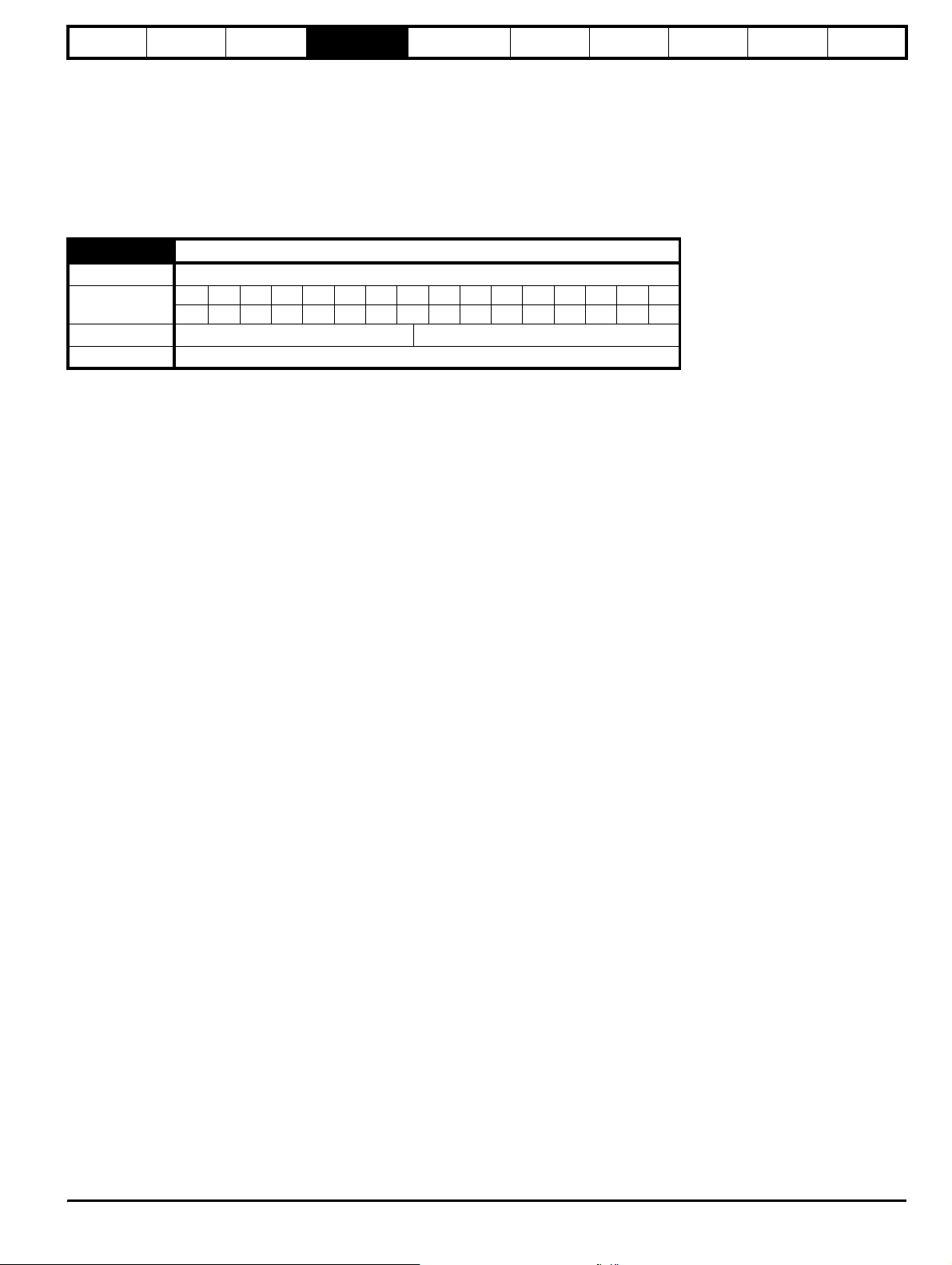
Parameter
structure
Keypad and
display
Parameter x.00
Parameter
description format
Advanced parameter
descriptions
3. When a destination is changes the old destination is written to zero,
unless the destination change is the result of loading defaults or
transferring parameters from a SMARTCARD. When defaults are
loaded the old destination is set to its default value. When
parameters are loaded from a SMARTCARD the old destination
retains its old value unless a SMARTCARD value is written to it.
4.3 Update rates
Update rates are given for every parameter in the hearder table as
shown below.
3.03 Speed error
Drive modes Closed-loop vector, Servo
Coding
Range Closed-loop vector, Servo ±SPEED_MAX rpm
Update rate 4ms write
Bit SP FI DE Txt VM DP ND RA NC NV PT US RW BU PS
1 11111
Macros
Serial comms
protocol
Electronic
nameplate
Performance
Feature look-
up table
Some parameters have an increased update in special circumstances.
4.3.1 Speed reference update rate
The normal update rate for the speed references (via menu 1) is 4ms,
however it is possible to reduce the sample time to 250µs by selecting
the reference from particular sources. The fast update rate is only
possible provided the conditions given below are met. (Note: high speed
updating is not provided for frequency references - i.e. Open-loop
mode.)
Analog input references (not including I/O expansion Solutions
Module)
1. The reference must be derived via Pr 1.36 or Pr 1.37
2. The analog inputs must be in voltage mode with zero offset
3. Bipolar mode must be used or unipolar mode with the minimum
speed (Pr 1.07) set to zero
4. No skip bands are enabled, i.e. Pr 1.29, Pr 1.31 and Pr 1.33 must be
zero.
5. The jog and velocity feed-forward references must not be enabled.
Applications and fieldbus Solutions Modules
Pr 91.02 must be used to define the speed reference (this parameter is
only visible from the Solutions Modules). Any value written to Pr 91.02
should be automatically mapped into preset Pr 1.21 by the Solutions
Module.
In fast update mode the references are sampled every 250µs. A sliding
window filter may be applied to analog input 1 (see Pr 7.26) in normal or
high speed updating modes. The default value for this filter is 4ms,
therefore Pr 7.26 must be set to zero to obtain the fastest possible
update rate.
When fast updating is used the scaling is performed by a simple
multiplication. This minimises software execution time, but also ensures
that there is no loss of resolution from the v to f converter used to
implement analog input 1. Therefore the speed of the motor may be
controlled with infinite resolution from analog input 1 except for
deadband effects around zero reference. The scale factor used for the
multiplication cannot exactly duplicate the scaling for the two stage
conversion (i.e. conversion in menu 7 to a percentage of full scale, and
conversion to 0.1rpm units) used when high speed updating is not in
operation. Therefore the absolute scaling of the analog inputs varies
slightly between normal and high speed updating. The amount of
difference depends on the maximum speed, user scaling in menu 7, and
the analog input 1 the filter time. The worst case difference for analog
input 1 is 0.12% of full scale, and for analog inputs 2 and 3 the difference
is less than 0.12% with a maximum speed of 50rpm or more. Typical
differences (1500rpm maximum speed, menu 7 scaling of 1.000, analog
input 1 filter of 4ms) are 0.015% for analog input 1 and 0.004% for
analog inputs 2 and 3.
4.3.2 Hard speed reference update rate
The normal update rate for the hard speed reference is 4ms, however it
is possible to reduce the sample time to 250µs by selecting the
reference from particular sources. The fast update rate is only possible
provided the conditions given below are met.
Analog inputs (not including I/O expansion Solutions Module)
The analog inputs must be in voltage mode with zero offset
Limitations are the same as for the references via menu 1 described
above.
Applications and fieldbus Solutions Modules
For faster update rate Pr 91.03 must be used (this parameter is only
visible from the Solutions Modules). Any value written to Pr 91.03 is
automatically mapped into the hard speed reference Pr 3.22.
Encoder reference
It is possible to use the drive encoder as the source for the hard speed
reference. To do this the drive encoder reference destination (Pr 3.46)
should be routed to the hard speed reference parameter. If, and only if,
the maximum drive encoder reference (Pr 3.43) is set to the same value
as the maximum reference value (SPEED_FREQ_MAX), and the
scaling (Pr 3.44) is 1.000, the drive takes the encoder pulses directly.
This gives a form of reference slaving where the integral term in the
speed controller accumulates all pulses from the reference and tries to
match them to the feedback from the motor encoder. Pulses are lost if
the reference reaches a minimum or maximum limit including zero speed
in unipolar mode. The reference is sampled every 250µs. When a
position feedback Solutions Module writes to the hard speed reference,
although the module can write every 250µs, the data is only acted on
every 4ms. When the reference comes from a Solutions Module there is
no guarantee that all pulses are counted. The encoder reference can be
scaled in high speed update mode by modifying the number of encoder
lines per revolution.
4.3.3 Torque reference update rate
The normal update rate for the torque reference (Pr 4.08) is 4ms,
however it is possible to reduce the sample time to 250µs by selecting
the reference from particular sources, but only in closed-loop vector or
servo modes. The fast update rate is only possible provided the
conditions given below are met.
Analog inputs 2 or 3 on the drive
The analog inputs must be in voltage mode with zero offset.
Unid rive SP Ad vanced User Guide 21
Issue Number: 7 www.controltechniques.com
Page 22
Parameter
structure
Keypad and
display
Parameter x.00
Parameter
description format
Advanced parameter
descriptions
Macros
5 Advanced parameter descriptions
5.1 Overview
Table 5-1 Menu descriptions
Menu no. Description
1 Frequency / speed reference
2Ramps
3 Slave frequency, speed feedback and speed control
4 Torque and current control
5 Motor control
6 Sequencer and clock
7 Analog I/O
8 Digital I/O
9 Programmable logic, motorised pot and binary sum
10 Status and trips
11 General drive set-up
12 Threshold detectors and variable selectors
13 Position control
14 User PID controller
15, 16, 17 Solutions Module slots
18 Application menu 1
19 Application menu 2
20 Application menu 3
21 Second motor parameters
Table 5-2 gives a full key of the coding which appears in the following parameter tables.
Table 5-2 Key to parameter coding
Coding Attribute
Bit 1 bit parameter
SP Spare: not used
Filtered: some parameters which can have rapidly changing
FI
values are filtered when displayed on the drive keypad for
easy viewing.
Destination: indicates that this parameter can be a
DE
destination parameter.
Txt Text: the parameter uses text strings instead of numbers.
VM Variable maximum: the maximum of this parameter can vary.
Decimal place: indicates the number of decimal places used
DP
by this parameter.
No default: when defaults are loaded (except when the drive
ND
is manufactured or on EEPROM failure) this parameter is not
modified.
Rating dependant: this parameter is likely to have different
values and ranges with drives of different voltage and current
ratings. These parameters are not transferred by
RA
SMARTCARDs when the rating of the destination drive is
different from the source drive.
Not cloned: not transferred to or from SMARTCARDs during
NC
cloning.
NV Not visible: not visible on the keypad.
PT Protected: cannot be used as a destination.
User save: saved in drive EEPROM when the user initiates a
US
parameter save.
RW Read/write: can be written by the user.
Bit default one/unsigned: Bit parameters with this flag set to
one have a default of one (all other bit parameters have a
BU
default of zero. Non-bit parameters are unipolar if this flag is
one.
Power-down save: automatically saved in drive EEPROM at
PS
power-down.
Serial comms
protocol
Electronic
nameplate
Performance
Feature look-
up table
22 Unidrive SP Advanced User Guide
www.controltechniques.com Issue Number: 7
Page 23

Parameter
structure
Keypad and
display
Parameter
x.00
Parameter
description format
Advanced parameter
descriptions
Macros
Serial comms
protocol
Electronic
nameplate
Performance
Feature look-
up table
Menu 1
Unid rive SP Ad vanced User Guide 23
Issue Number: 7 www.controltechniques.com
Page 24
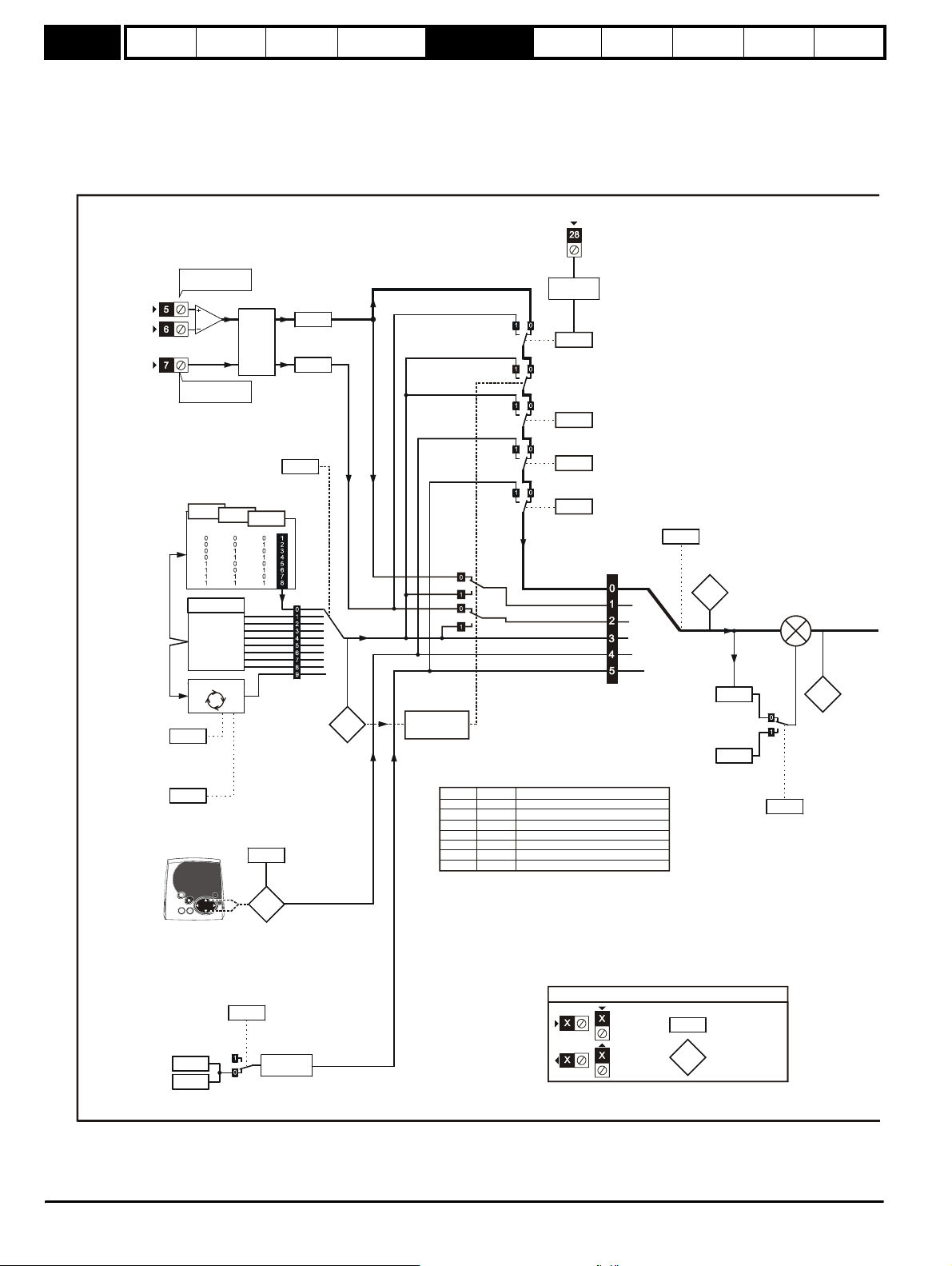
Menu 1
Parameter
structure
Keypad and
display
Parameter
x.00
Parameter
description format
Advanced parameter
descriptions
Macros
Serial comms
protocol
Electronic
nameplate
Performance
Feature look-
up table
5.2 Menu 1: Frequency/speed reference
Menu 1 controls the main reference selection. When the drive operates in open-loop mode a frequency reference is produced, and when Unidrive SP
operates in closed-loop vector or servo modes a speed reference is produced.
Figure 5-1 Menu 1 logic diagram
LOCAL/REMOTE
Analog reference
Analog input 1
Menu 7
Analog input 2
Preset reference
Preset reference
1.47
1.21 ~ 1.28
Preset
references
1 to 8
Scan timer
*selector
1.46
Preset reference select bits 1 ~ 3
1.16
Preset
reference
scan time
1.48
Preset refere nce
Scan-timer reset
Keypad reference
1.45
1.51
Analog
reference 1
1.36
1.37
Analog
reference 2
1.15
1.20
Preset
reference
selected
indicator
Power-up keypad
control mode
reference
Menu 8
Analog reference 2
1.41
select
Preset reference
1.42
select
Keypad refere nce
1.43
select
Precision reference
1.44
select
Reference
*selector
1.14
Reference selec ted
indicator
1.49
+
+
1.09
1.01
Level of
reference
selected
1.50
Pr set to
1.50
greater than 1
Pr 1.49
Pr 1.50
1
1
2
2
3
4
5
Reference being used
1
Analog reference 1
>1
Preset reference defined by Pr
1
Analog reference 2
>1
Preset reference defined by Pr
x
Preset reference defined by Pr
x
Keypad reference
x
Preceision reference
1.50
1.50
1.50
1.38
Reference
percentage
trim
1.04
Reference
offset
Reference
offset mode
select
1.17
Keypad
Reference
Precision reference
Precision
reference
1.18
1.19
Precision
reference trim
Precision-ref erence
update disable
1.20
Memory
The parameters are all shown in their default settings
Input
terminals
Output
terminals
Key
0.XX
0.XX
Read-write (RW)
paramete r
Read-only (RO)
paramete r
*Refer to Pr 1.14 on page 29.
24 Unidrive SP Advanced User Guide
www.controltechniques.com Issue Number: 7
Page 25
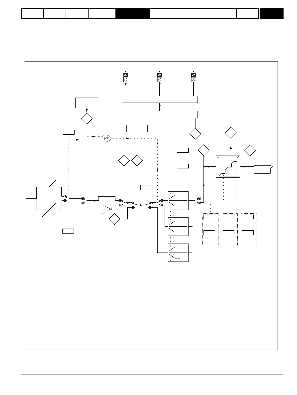
Parameter
structure
Keypad and
display
Parameter
x.00
Parameter
description format
Advanced parameter
descriptions
JOG RUN FORWARD RUN R EVERSE
Macros
Serial comms
protocol
Electronic
nameplate
Performance
Feature look-
up table
Menu 1
Bipolar
reference
select
Jog selected
indicator
1.10
1.05
Jog
reference
Menu 6
Sequencer
1.13
Reverse
selected
indicator
x(-1)
Velo city
feed-forward
reference
1.39
Position control
1.12
Menu 13
1.40
Sequencer (Menu 6)
Feed-forward
selected
indicator
Negative
minimum
speed
select
1.08
Menu 8
1.06
Maximum
freq./speed
"clamp"
1.07
Minimum
freq./speed
"clamp"
(Maximum
reverse
freq./speed)
[1.06]
[1.07]
[1.07]
[1.06]
[1.06]
[1.06]
[1.06]
Reference in skip
freq./speed band
indicator
Reference
1.11
enabled
indicator
Pre-filter
1.02 1.03
reference
1.29
Skip freq./
speed 1
1.30
Skip freq./
speed band
1
1.35
1.31
Skip freq./
speed 2
1.32
Skip freq./
speed band
2
Pre-ramp
reference
1.33
Skip freq./
speed 3
1.34
Skip freq./
speed band
3
Menu 2
[1.07]
Unid rive SP Ad vanced User Guide 25
Issue Number: 7 www.controltechniques.com
Page 26
Menu 1
Parameter
structure
Keypad and
display
Parameter
x.00
Parameter
description format
Advanced parameter
descriptions
Macros
1.01 Frequency/speed reference selected
Drive modes Open-loop, Closed-loop vector, Servo
Coding
Bit SP FI DE Txt VM DP ND RA NC NV PT US RW BU PS
11111
Range Open-loop, Closed-loop vector, Servo ±SPEED_FREQ_MAX Hz/rpm
Update rate 4ms write
1.02 Pre-skip filter reference
Drive modes Open-loop, Closed-loop vector, Servo
Coding
Bit SP FI DE Txt VM DP ND RA NC NV PT US RW BU PS
11111
Range Open-loop, Closed-loop vector, Servo ±SPEED_FREQ_MAX Hz/rpm
Update rate 4ms write
1.03 Pre-ramp reference
Drive modes Open-loop, Closed-loop vector, Servo
Coding
Bit SP FI DE Txt VM DP ND RA NC NV PT US RW BU PS
11111
Range Open-loop, Closed-loop vector, Servo ±SPEED_FREQ_MAX Hz/rpm
Update rate 4ms write
Serial comms
protocol
Electronic
nameplate
Performance
Feature look-
up table
1.04 Reference offset
Drive modes Open-loop, Closed-loop vector, Servo
Coding
Range
Bit SP FI DE Txt VM DP ND RA NC NV PT US RW BU PS
111
Open-loop
Closed-loop vector, Servo
±3,000.0 Hz
±40,000.0 rpm
Default Open-loop, Closed-loop vector, Servo 0
Update rate
Background read when precision reference is active
4ms write otherwise
See Pr 1.09 on page 28.
1.05 Jog reference
Drive modes Open-loop, Closed-loop vector, Servo
Coding
Range
Bit SP FI DE Txt VM DP ND RA NC NV PT US RW BU PS
1111
Open-loop
Closed-loop vector, Servo
0 to 400.0 Hz
0 to 4,000.0 rpm
Default Open-loop, Closed-loop vector, Servo 0.0
Update rate 4ms read
Reference used for jogging. See section 5.7 Menu 6: Sequencer and clock on page 122 for details on when the jog mode can be activated. The jog
reference can be used for relative jogging in digital lock mode (see section 5.14 Menu 13: Position control on page 206).
26 Unidrive SP Advanced User Guide
www.controltechniques.com Issue Number: 7
Page 27
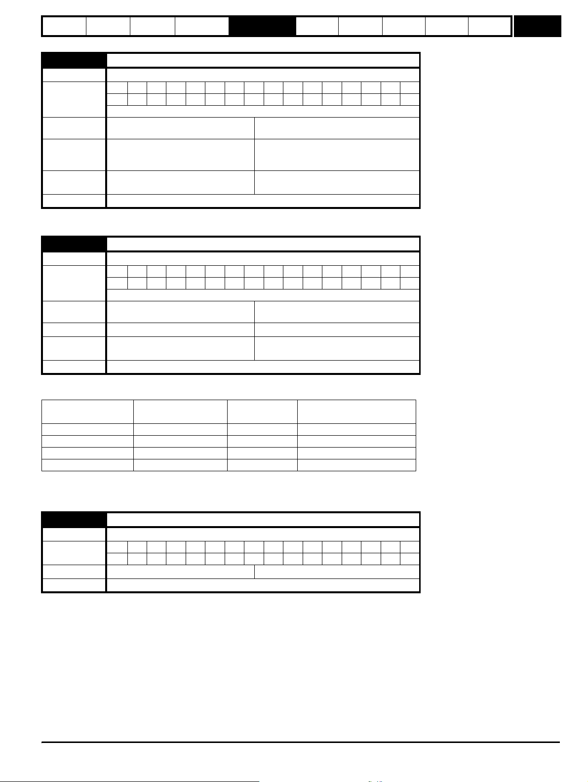
Parameter
structure
Keypad and
display
Parameter
x.00
Parameter
description format
Advanced parameter
descriptions
Macros
Serial comms
protocol
Electronic
nameplate
Performance
Feature look-
up table
Menu 1
1.06
Maximum reference clamp
Drive modes Open-loop, Closed-loop vector, Servo
Bit SP FI DE Txt VM DP ND RA NC NV PT US RW BU PS
Coding
1 111
Closed-loop vector and servo: VM = 1
Range
Default
Second motor
parameter
Open-loop
Closed-loop vector and Servo
Open-loop
Closed-loop vector
Servo
Open-loop, Closed-loop vector, Servo Pr 21.01
0 to 3,000.0 Hz
±SPEED_LIMIT_MAX rpm
EUR: 50.0, USA: 60.0
EUR: 1,500.0, USA: 1,800.0
3,000.0
Update rate Background read
See below.
1.07 Minimum reference clamp
Drive modes Open-loop, Closed-loop vector, Servo
Bit SP FI DE Txt VM DP ND RA NC NV PT US RW BU PS
Coding
1111
Closed-loop vector and Servo: VM = 1
Range
Open-loop
Closed-loop vector and Servo
±3,000.0 Hz
±SPEED_LIMIT_MAX rpm
Default Open-loop, Closed-loop vector, Servo 0.0
Second motor
parameter
Open-loop, Closed-loop vector, Servo Pr 21.02
Update rate Background read
The range shown for Pr 1.07 shows the range used for scaling purposes (i.e. for routing to an analog output etc.). Further range restrictions are
applied as given below.
Pr 1.08
(Neg min ref enable)
Pr 1.10
(Bipolar mode enable)
Open-loop Closed-loop vector and Servo
0 0 0 to Pr 1.06 0 to Pr 1.06
010 0
1 0 -3,000 to 0Hz -SPEED_LIMIT_MAX to 0 rpm
1 1 -3,000 to 0Hz -SPEED_LIMIT_MAX to 0 rpm
The same limits are applied to Pr 21.02, but based on the value of Pr 21.01.
(If the second motor map is selected Pr 21.01 is used instead of Pr 1.06 and Pr 21.02 instead of Pr 1.07)
1.08 Negative minimum reference clamp enable
Drive modes Open-loop, Closed-loop vector, Servo
Coding
Bit SP FI DE Txt VM DP ND RA NC NV PT US RW BU PS
111
Default Open-loop, Closed-loop vector, Servo 0
Update rate Background read
The effects of the reference clamps (Pr 1.06 and 1.07), the negative minimum clamp enable (Pr 1.08) and the bipolar reference enable parameters
are defined below.
The variable maximum limit for reference parameters, SPEED_FREQ_MAX, is defined as:
If Pr 1.08 = 0: SPEED_FREQ_MAX = Pr 1.06
If Pr 1.08=1: SPEED_FREQ_MAX is Pr 1.06 or -Pr 1.07 whichever is the largest
(If the second motor map is selected Pr 21.01 is used instead of Pr 1.06 and Pr 21.02 instead of Pr 1.07)
Unid rive SP Ad vanced User Guide 27
Issue Number: 7 www.controltechniques.com
Page 28
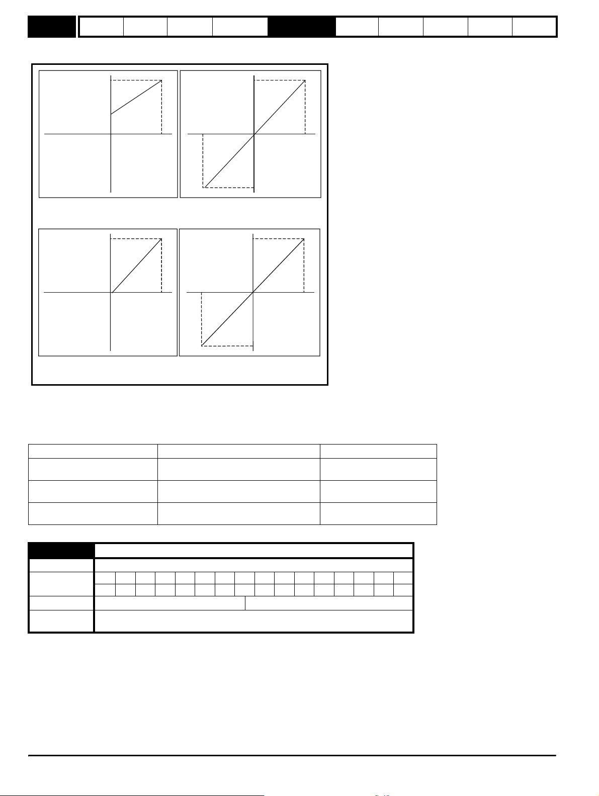
Menu 1
Parameter
structure
Keypad and
display
Parameter
x.00
Parameter
description format
Advanced parameter
descriptions
Macros
Serial comms
protocol
Electronic
nameplate
Performance
Feature look-
Analog input scaling
The following diagrams show the scaling applied when analog inputs are used to define the reference and are routed via Pr 1.36 or Pr 1.37.
up table
SPEED_FREQ_MAX
Pr
1.07
-100% 100%
Pr =0 (
1.10
unipolar mode)
1.08
Pr =0 (
SPEED_FREQ_MAX
-100% 100%
Pr =0 (
Pr =1 (
neg min ref disabled)
1.10
unipolar mode)
1.08
neg min ref enabled)
SPEED_FREQ_MAX
-100% 100%
-SPEED_FREQ_MAX
Pr =1 (bipolar mode)
1.10
Pr =0 (
1.08
neg min ref disabled)
SPEED_FREQ_MAX
-100% 100%
-SPEED_FREQ_MAX
Pr =1 (bipolar mode)
1.10
Pr =1 (
1.08
neg min ref enabled)
Reference limits
With reference to the block diagram for Menu 1 (Figure 5-1 on page 24) the following table shows the limits applied to the reference by variaous
blocks in the reference system. It should be noted that the minimum limit in the main reference limits block changes when either the jog reference or
velocity feedforward references are active. When one of these is active: if Pr 1.08 = 0 the minimum = -Pr 1.06 [-Pr 21.01 for motor map2], if Pr 1.08
= 1 the minimum = -Pr 1.07 [-Pr 21.02 for motor map 2].
Minimum Maximum
Keypad control reference (Pr 1.17)
Bipolar/unipolar selector
Main reference limits
Unipolar mode: Pr 1.07, or 0 if Pr 1.07 < 0
Bipolar mode: -SPEED_FREQ_MAX
Unipolar mode: Pr 1.07, or 0 if Pr 1.07 < 0
Bipolar mode: no limit applied
Neg minimum ref disabled: -Pr 1.06
Neg minimum ref enabled: Pr 1.07
SPEED_FREQ_MAX
No maximum limit applied
Pr 1.06
1.09 Reference offset select
Drive modes Open-loop, Closed-loop vector, Servo
Coding
Bit SP FI DE Txt VM DP ND RA NC NV PT US RW BU PS
111
Default Open-loop, Closed-loop vector, Servo 0
Update rate
Background read when precision reference is active
4ms read otherwise
When this parameter is 0 the reference is given by
Pr 1.01 = selected reference x (100 + Pr 1.38) / 100
and when this parameter is 1 the reference is given by
Pr 1.01 = selected reference + Pr 1.04
28 Unidrive SP Advanced User Guide
www.controltechniques.com Issue Number: 7
Page 29
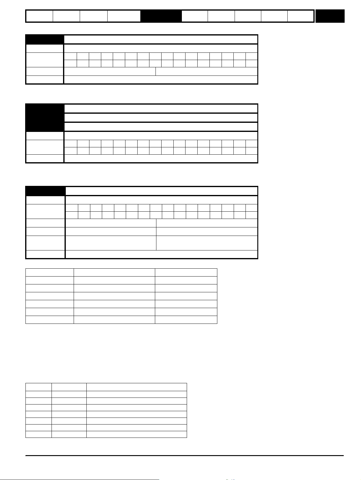
Parameter
structure
Keypad and
display
Parameter
x.00
Parameter
description format
Advanced parameter
descriptions
Macros
Serial comms
protocol
Electronic
nameplate
Performance
Feature look-
up table
Menu 1
1.10 Bipolar reference enable
Drive modes Open-loop, Closed-loop vector, Servo
Coding
Bit SP FI DE Txt VM DP ND RA NC NV PT US RW BU PS
111
Default Open-loop, Closed-loop vector, Servo 0
Update rate 4ms read
See Pr 1.08 on page 27.
1.11 Reference enabled indicator
1.12 Reverse selected indicator
1.13 Jog selected indicator
Drive modes Open-loop, Closed-loop vector, Servo
Coding
Bit SP FI DE Txt VM DP ND RA NC NV PT US RW BU PS
111
Update rate 4ms read
These parameters are controlled by the drive sequencer as defined in Menu 6. They select the appropriate reference as commanded by the drive
logic.
1.14 Reference selector
Drive modes Open-loop, Closed-loop vector, Servo
Coding
Bit SP FI DE Txt VM DP ND RA NC NV PT US RW BU PS
1111
Range Open-loop, Closed-loop vector, Servo 0 to 5
Default Open-loop, Closed-loop vector, Servo 0 (A1.A2)
Second motor
parameter
Open-loop, Closed-loop vector, Servo Pr 21.03
Update rate 4ms read
Pr 1.14 defines how the value of Pr 1.49 is derived as follows:
Value of Pr 1.14 Display String Pr 1.49
0 A1.A2 (Analog ref 1. Analog ref 2) *Selected by terminal input
1 A1.Pr (Analog ref 1. Preset speeds) 1
2 A2.Pr (Analog ref 2. Preset speeds) 2
3 Pr (Preset speeds) 3
4 Pad (Keypad reference) 4
5 Prc (Precision reference) 5
*Pr 1.41 to Pr 1.44 can be controlled by digital inputs to force the value of Pr 1.49:
all bits equal to zero gives 1,
Pr 1.41 = 1 then Pr 1.49 = 2
Pr 1.42 = 1 then Pr 1.49 = 3
Pr 1.43 = 1 then Pr 1.49 = 4
Pr 1.44 = 1 then Pr 1.49 = 5
The bit parameters with lower numbers have priority over those with higher numbers.
Pr 1.49 and Pr 1.50 then define the reference as follows:
Pr 1.49 Pr 1.50 Reference
1 1 Analog reference 1 (Pr 1.36)
1 >1 Preset defined by Pr 1.50 (Pr 1.21 to Pr 1.28)
2 1 Analog reference 2 (Pr 1.37)
2 >1 Preset defined by Pr 1.50 (Pr 1.21 to Pr 1.28)
3 x** Preset defined by Pr 1.50 (Pr 1.21 to Pr 1.28)
4 x** Keypad reference (Pr 1.17)
5 x** Precision reference (Pr 1.18 and Pr 1.19)
** x = any value
Unid rive SP Ad vanced User Guide 29
Issue Number: 7 www.controltechniques.com
Page 30
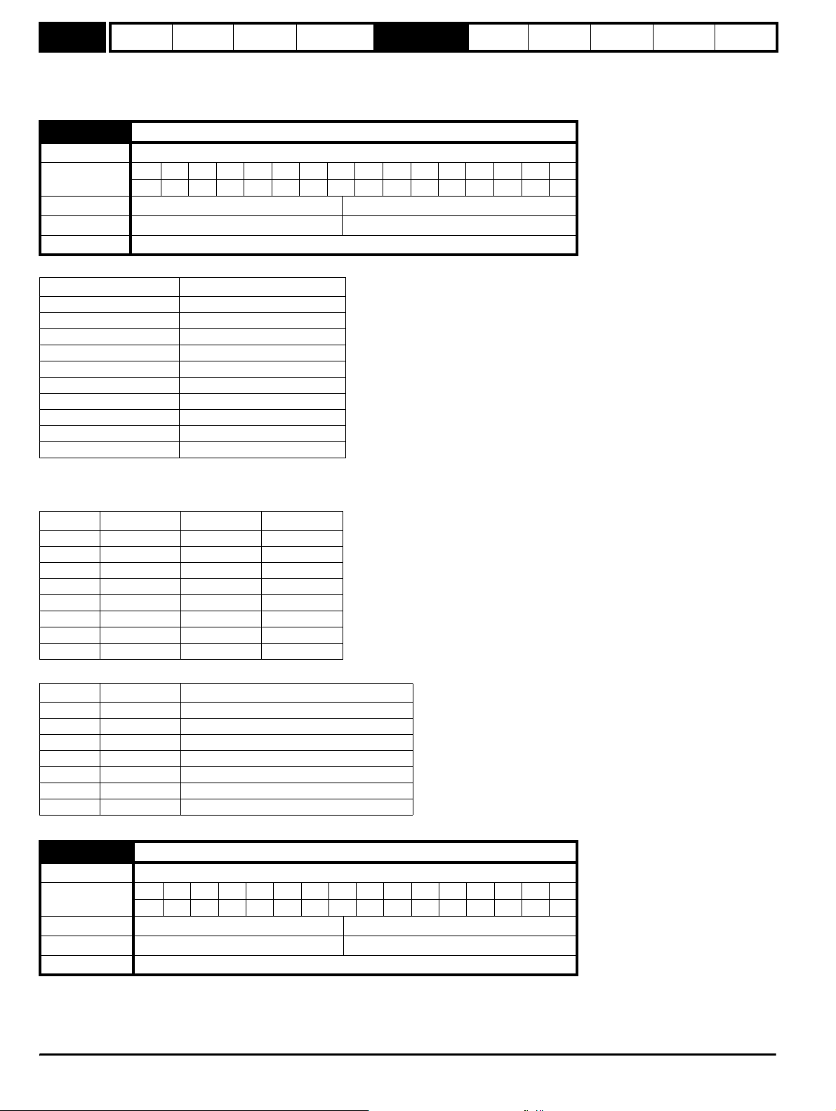
Menu 1
Parameter
structure
Keypad and
display
Parameter
x.00
Parameter
description format
Advanced parameter
descriptions
Macros
Serial comms
protocol
Electronic
nameplate
Performance
Feature look-
up table
Keypad reference
If Keypad reference is selected the drive sequencer is controlled directly by the keypad keys and the keypad reference parameter (Pr 1.17) is
selected. The sequencing bits, Pr 6.30 to Pr 6.34, have no effect and jog is disabled.
1.15 Preset selector
Drive modes Open-loop, Closed-loop vector, Servo
Coding
Bit SP FI DE Txt VM DP ND RA NC NV PT US RW BU PS
111
Range Open-loop, Closed-loop vector, Servo 0 to 9
Default Open-loop, Closed-loop vector, Servo 0
Update rate 4ms read
Pr 1.15 defines how the value of Pr 1.50 is derived as follows:
Value of Pr 1.15 Pr 1.50
0 Selected by terminal input*
11
22
33
44
55
66
77
88
9 Selected by timer**
*Pr 1.45 to Pr 1.47 can be controlled by digital inputs to define the value of Pr 1.50 as follows:
**The presets are selected automatically in turn. Pr 1.16 defines the time between each change.
Pr 1.47 Pr 1.46 Pr 1.45 Pr 1.50
0001
0012
0103
0114
1005
1016
1107
1118
Pr 1.49 and Pr 1.50 then define the reference as follows:
Pr 1.49 Pr 1.50 Reference
1 1 Analog reference 1 (Pr 1.36)
1 >1 Preset defined by Pr 1.50 (Pr 1.21 to Pr 1.28)
2 1 Analog reference 2 (Pr 1.37)
2 >1 Preset defined by Pr 1.50 (Pr 1.21 to Pr 1.28)
3 x Preset defined by Pr 1.50 (Pr 1.21 to Pr 1.28)
4 x Keypad reference (Pr 1.17)
5 x Precision reference (Pr 1.18 and Pr 1.19)
1.16 Preset reference selector timer
Drive modes Open-loop, Closed-loop vector, Servo
Coding
Bit SP FI DE Txt VM DP ND RA NC NV PT US RW BU PS
1111
Range Open-loop, Closed-loop vector, Servo 0 to 400.0 s
Default Open-loop, Closed-loop vector, Servo 10.0
Update rate Background read
This parameter defines the time between preset reference changes when Pr 1.15 is set to 9. If Pr 1.48 is set to 1 then the preset counter and timer are
reset and preset 1 will be selected.
30 Unidrive SP Advanced User Guide
www.controltechniques.com Issue Number: 7
Page 31

Parameter
structure
Keypad and
display
Parameter
x.00
Parameter
description format
Advanced parameter
descriptions
Macros
Serial comms
protocol
Electronic
nameplate
Performance
Feature look-
up table
Menu 1
1.17 Keypad control mode reference
Drive modes Open-loop, Closed-loop vector, Servo
Coding
Bit SP FI DE Txt VM DP ND RA NC NV PT US RW BU PS
11 1 1 1
Range Open-loop, Closed-loop vector, Servo ±SPEED_FREQ_MAX Hz/rpm
Default Open-loop, Closed-loop vector, Servo 0.0
Update rate 4ms read
The drive can be controlled from the keypad if Pr 1.14 is set to 4. The Stop and Run keys automatically become active (the Reverse key may be
optionally enabled with Pr 6.13). The frequency/speed reference is defined by Pr 1.17. This is a read only parameter that can only be adjusted in
status mode by pressing the Up or Down keys. If keypad control mode is selected, then pressing the Up or Down keys in status mode will cause the
drive to automatically display the keypad reference and adjust it in the relevant direction. This can be done whether the drive is disabled or running. If
the Up or Down keys are held the rate of change of keypad reference increases with time. The units used for to display the keypad reference for
different modes are given below.
Mode Unit
Open loop Hz
Closed loop rpm
Servo rpm
See also Pr 1.51 on page 35 (Power-up keypad control mode reference).
1.18 Precision reference coarse
Drive modes Open-loop, Closed-loop vector, Servo
Coding
Bit SP FI DE Txt VM DP ND RA NC NV PT US RW BU PS
11 11
Range Open-loop, Closed-loop vector, Servo ±SPEED_FREQ_MAX Hz/rpm
Default Open-loop, Closed-loop vector, Servo 0.0
Update rate Background read
See below.
1.19 Precision reference fine
Drive modes Open-loop, Closed-loop vector, Servo
Coding
Range
Bit SP FI DE Txt VM DP ND RA NC NV PT US RW BU PS
3111
Open-loop
Closed-loop vector, Servo
0.000 to 0.099 Hz
0.000 to 0.099 rpm
Default Open-loop, Closed-loop vector, Servo 0.000
Update rate Background read
Open loop
The frequency reference resolution is restricted to 0.1Hz from normal parameters, but the resolution can be improved by using the precision
reference. Pr 1.18 defines the coarse part of reference (either positive or negative) with a resolution of 0.1Hz and Pr 1.19 defines the fine part of the
reference (always positive) with a resolution of 0.001Hz. The final reference is given by Pr 1.18 + Pr 1.19. Therefore Pr 1.19 increases positive
references away from zero, and decreases negative references towards zero.
Closed loop
As with open-loop a higher resolution speed reference can be programmed by selecting these parameters. In this case the speed will have a
resolution of 0.001 rpm.
1.20 Precision reference update disable
Drive modes Open-loop, Closed-loop vector, Servo
Coding
Bit SP FI DE Txt VM DP ND RA NC NV PT US RW BU PS
111
Default Open-loop, Closed-loop vector, Servo 0
Update rate Background read
When this bit is at 0 the precision reference parameters are read and stored in internal memory. Because the precision reference has to be set in two
parameters, this bit is provided to prevent the drive reading the parameters while the reference is being updated. Instead, the drive uses the value
Unid rive SP Ad vanced User Guide 31
Issue Number: 7 www.controltechniques.com
Page 32

Menu 1
Parameter
structure
Keypad and
display
Parameter
x.00
Parameter
description format
Advanced parameter
descriptions
stored in memory preventing the possibility of data skew.
1.21 Preset reference 1
1.22 Preset reference 2
1.23 Preset reference 3
1.24 Preset reference 4
1.25 Preset reference 5
1.26 Preset reference 6
1.27 Preset reference 7
1.28 Preset reference 8
Drive modes Open-loop, Closed-loop vector, Servo
Coding
Bit SP FI DE Txt VM DP ND RA NC NV PT US RW BU PS
11 11
Range Open-loop, Closed-loop vector, Servo ±SPEED_FREQ_MAX Hz/rpm
Default Open-loop, Closed-loop vector, Servo 0.0
Update rate 4ms read
1.29 Skip reference 1
1.31 Skip reference 2
1.33 Skip reference 3
Drive modes Open-loop, Closed-loop vector, Servo
Coding
Bit SP FI DE Txt VM DP ND RA NC NV PT US RW BU PS
1111
Closed-loop vector and servo DP = 0
Range
Default
Open-loop
Closed-loop vector, Servo
Open-loop
Closed-loop vector, Servo
0.0 to 3,000.0 Hz
0 to 40,000 rpm
0.0
0
Update rate Background read
See below.
Macros
Serial comms
protocol
Electronic
nameplate
Performance
Feature look-
up table
1.30 Skip reference band 1
1.32 Skip reference band 2
1.34 Skip reference band 3
Drive modes Open-loop, Closed-loop vector, Servo
Coding
Bit SP FI DE Txt VM DP ND RA NC NV PT US RW BU PS
1111
Closed-loop vector and servo DP = 0
Range
Default
Open-loop
Closed-loop vector, Servo
Open-loop
Closed-loop vector, Servo
0.0 to 25.0 Hz
0 to 250 rpm
0.5
5
Update rate Background read
Three skip references are available to prevent continuous operation at a speed that would cause mechanical resonance. When a skip reference
parameter is set to 0 that filter is disabled. The skip reference band parameters define the frequency or speed range either side of the programmed
skip reference, over which references are rejected. The actual reject band is therefore twice that programmed in these parameters, the skip reference
parameters defining the centre of the band. When the selected reference is within a band the lower limit of the band is passed through to the ramps
such that reference is always less than demanded.
32 Unidrive SP Advanced User Guide
www.controltechniques.com Issue Number: 7
Page 33

Parameter
structure
Keypad and
display
Parameter
x.00
Parameter
description format
Advanced parameter
descriptions
Macros
Serial comms
protocol
Electronic
nameplate
Performance
Feature look-
up table
Menu 1
1.35 Reference in rejection zone
Drive modes Open-loop, Closed-loop vector, Servo
Coding
Bit SP FI DE Txt VM DP ND RA NC NV PT US RW BU PS
1 111
Update rate 4ms write
This parameter indicates that the selected reference is within one of the skip reference zones such that the motor speed is not as demanded.
1.36 Analog reference 1
1.37 Analog reference 2
Drive modes Open-loop, Closed-loop vector, Servo
Coding
Bit SP FI DE Txt VM DP ND RA NC NV PT US RW BU PS
111 1
Range Open-loop, Closed-loop vector, Servo ±SPEED_FREQ_MAX Hz/rpm
Default Open-loop, Closed-loop vector, Servo 0
Update rate 4ms write
Although most parameters can be controlled from analog inputs, these two parameters are a special case in that if an analog input is directed to one
of these parameters, the scan rate of that analog input is increased to 250µs as long as:
1. The reference must be derived via Pr 1.36 or Pr 1.37
2. The analog inputs must be in voltage mode with zero offset
3. Bipolar mode must be used or unipolar mode with the minimum speed (Pr 1.07) set to zero
4. No skip bands are enabled, i.e. Pr 1.29, Pr 1.31 and Pr 1.33 must be zero.
5. The jog and velocity feed-forward references must not be enabled.
These are special parameters when a non-bit type quantity uses these parameters as a destination (not just from analog inputs). The scaling and
limiting applied is as described with Pr 1.08 on page 27.
1.38 Percentage trim
Drive modes Open-loop, Closed-loop vector, Servo
Coding
Bit SP FI DE Txt VM DP ND RA NC NV PT US RW BU PS
21 1
Range Open-loop Closed-loop vector, Servo ±100.00 %
Default Open-loop Closed-loop vector, Servo 0
Update rate 4ms read
See Pr 1.09 on page 28.
1.39 Velocity feed forward
Drive modes Open-loop, Closed-loop vector, Servo
Coding
Range
Bit SP FI DE Txt VM DP ND RA NC NV PT US RW BU PS
1111
Open-loop
Closed-loop vector, Servo
±3,000.0 Hz
±40,000.0 rpm
Update rate 4ms read
This parameter indicates the velocity feed forward reference when position control is used (see section 5.14 Menu 13: Position control on page 197).
1.40 Velocity feed forward select
Drive modes Open-loop, Closed-loop vector, Servo
Coding
Bit SP FI DE Txt VM DP ND RA NC NV PT US RW BU PS
1 111
Update rate 4ms write
This bit indicates that the position controller has selected the velocity feed forward as a reference for the drive
Unid rive SP Ad vanced User Guide 33
Issue Number: 7 www.controltechniques.com
Page 34

Menu 1
Parameter
structure
Keypad and
display
Parameter
x.00
Parameter
description format
Advanced parameter
descriptions
Macros
Serial comms
protocol
Electronic
nameplate
Performance
Feature look-
up table
1.41 Analog reference 2 select
1.42 Preset reference select
1.43 Keypad reference select
1.44 Precision reference select
1.45 Preset reference 1 select
1.46 Preset reference 2 select
1.47 Preset reference 3 select
Drive modes Open-loop, Closed-loop vector, Servo
Coding
Bit SP FI DE Txt VM DP ND RA NC NV PT US RW BU PS
111
Default Open-loop, Closed-loop vector, Servo 0
Update rate 4ms read
Pr 1.41 to Pr 1.44 control Pr 1.49. The priority order is Pr 1.44 (highest), Pr 1.43, Pr 1.42, Pr 1.41 (lowest). If more than one parameter is active, the
highest priority takes precedence.
Pr 1.41 = 1 forces Pr 1.49 = 2 (see table in Pr 1.14 on page 29 and Pr 1.15 on page 30)
Pr 1.42 = 1 forces Pr 1.49 = 3 (always selects preset references)
Pr 1.43 = 1 forces Pr 1.49 = 4 (always selects keypad control mode)
Pr 1.44 = 1 forces Pr 1.49 = 5 (always selects precision reference)
Pr 1.45 to Pr 1.47 control Pr 1.50.
Pr 1.45 controls Pr 1.50 bit 0*
Pr 1.46 controls Pr 1.50 bit 1*
Pr 1.47 controls Pr 1.50 bit 2*
*See the description with Pr 1.14 and Pr 1.15 on page 30 for more information.
1.48 Reference timer reset flag
Drive modes Open-loop, Closed-loop vector, Servo
Coding
Bit SP FI DE Txt VM DP ND RA NC NV PT US RW BU PS
111
Default Open-loop, Closed-loop vector, Servo 0
Update rate Background read
When this flag is set the preset timer for auto preset timer mode (Pr 01.15 = 9) is reset and preset 1 is selected. This can be used to start a new
sequence of reference selection by a programmable input terminal or function. When this bit is zero the preset selection will follow the timer even
when the drive is disabled.
1.49 Reference selected indicator
Drive modes Open-loop, Closed-loop vector, Servo
Coding
Bit SP FI DE Txt VM DP ND RA NC NV PT US RW BU PS
111 1
Range Open-loop, Closed-loop vector, Servo 1 to 5
Update rate 4ms write
Indicates the reference currently selected
1.50 Preset reference selected indicator
Drive modes Open-loop, Closed-loop vector, Servo
Coding
Bit SP FI DE Txt VM DP ND RA NC NV PT US RW BU PS
111 1
Range Open-loop, Closed-loop vector, Servo 1 to 8
Update rate 4ms write
Indicates the preset reference currently being selected
34 Unidrive SP Advanced User Guide
www.controltechniques.com Issue Number: 7
Page 35

Parameter
structure
Keypad and
display
Parameter
x.00
Parameter
description format
Advanced parameter
descriptions
Macros
1.51 Power-up keypad control mode reference
Drive modes Open-loop, Closed-loop vector, Servo
Coding
Bit SP FI DE Txt VM DP ND RA NC NV PT US RW BU PS
1111
Range Open-loop, Closed-loop vector, Servo 0 to 2
Default Open-loop, Closed-loop vector, Servo 0
Update rate N/A
Selects the value of the keypad control mode (Pr 1.17) at power-up as follows:
0 rESEt zero
1 LASt last value used before power-down
2 PrS1 Preset 1, Pr 1.21, before power-down
Serial comms
protocol
Electronic
nameplate
Performance
Feature look-
up table
Menu 1
Unid rive SP Ad vanced User Guide 35
Issue Number: 7 www.controltechniques.com
Page 36

Menu 2
Parameter
structure
Keypad and
display
Parameter
x.00
Parameter
description format
Advanced parameter
descriptions
Macros
Serial comms
protocol
Electronic
nameplate
Performance
Feature look-
up table
5.3 Menu 2: Ramps
The pre-ramp frequency or speed reference passes through the ramp block controlled by menu 2 before being used by the drive to produce the basic
output frequency (Open-loop modes), or as an input to the speed controller (Closed-loop vector or Servo modes). The ramp block includes: linear
ramps, an S ramp function for ramped acceleration and deceleration, deceleration ramp control to prevent rises in the DC bus voltage within the drive
that would cause an over-voltage trip if no braking resistor is fitted.
Figure 5-2 Menu 2 logic diagram
Acceleration rates 1 ~ 8
2.11
Acceleration rate 1
2.12
Acceleration rate 2
2.13
Acceleration rate 3
2.14
Acceleration rate 4
2.15
Acceleration rate 5
2.16
Acceleration rate 6
2.17
Acceleration rate 7
2.18
Acceleration rate 8
Acceleration rate select bits
2.34
0 0 0
0 0 1
0 1 0
0 1 1
1 0 0
1 0 1
1 1 0
1 1 1
2.33
2.32
2.32
Acceleration
rate selector
2.10
Key
Input
terminals
Output
terminals
0.XX
0.XX
Read-write (RW)
parameter
Read-only (RO)
parameter
The parameters are all shown at their default settings
Pre-ramp speed
reference
Preset reference
selected indicator
1.03
1.50
1
2
3
4
5
6
7
8
Jog selected
indicator
1.13
Jog acceleration
rate
2.19
Reverse
accel. rate
N
t
Forward
accel. rate
N
t
Acceleration
Ramp control
Ramp hold
2.03
Ramp mode
2.04
select*
36 Unidrive SP Advanced User Guide
www.controltechniques.com Issue Number: 7
Page 37

Parameter
structure
Keypad and
display
Parameter
x.00
Parameter
description format
* For more information refer to Pr 2.04 on page 38.
** For more information refer to Pr 2.06 on page 39.
Advanced parameter
descriptions
Deceleration
rate selector
2.20
Macros
Serial comms
protocol
Deceleration rate select bits
2.37
Electronic
nameplate
2.36
2.35
Performance
Feature look-
up table
Menu 2
Forward
Decel. rate
N
Deceleration
Ramp control
2.06
S-Ramp enable**
S-Ramp acceleration
2.07
limit
Standard ramp voltage*
2.08
Preset reference
1.50
selected indicator
Jog deceleration
2.29
Reverse
Decel. rate
N
t
t
rate
Current control
Menu 4
(Open-loop only)
+
1.13
_
Jog selected
indicator
Ramp
2.02
(Closed- loop only)
Ramps always enabled
in Open-loop
enable
d/dt
Inertia compensation
Post-ramp
reference
2.01
2.38
torque
(Closed-loop only)
Unid rive SP Ad vanced User Guide 37
Issue Number: 7 www.controltechniques.com
Page 38

Menu 2
Parameter
structure
Keypad and
display
Parameter
x.00
Parameter
description format
Advanced parameter
descriptions
Macros
2.01 Post ramp reference
Drive modes Open-loop, Closed-loop vector, Servo
Coding
Bit SP FI DE Txt VM DP ND RA NC NV PT US RW BU PS
11111
Range Open-loop, Closed-loop vector, Servo ±SPEED_FREQ_MAX Hz/rpm
Update rate 4ms write
2.02 Ramp enable
Drive modes Closed-loop vector, Servo
Coding
Bit SP FI DE Txt VM DP ND RA NC NV PT US RW BU PS
1111
Coding RW, Bit, US
Default Closed-loop vector and Servo 1
Update rate 4ms read
2.03 Ramp hold
Drive modes Open-loop, Closed-loop vector, Servo
Coding
Bit SP FI DE Txt VM DP ND RA NC NV PT US RW BU PS
111
Default Open-loop, Closed-loop vector, Servo 0
Update rate 4ms read
Serial comms
protocol
Electronic
nameplate
Performance
Feature look-
up table
If this bit is set the ramp will be held. If S ramp is enabled the acceleration will ramp towards zero causing the ramp output to curve towards a constant
speed. If a drive stop is demanded the ramp hold function is disabled.
2.04 Ramp mode select
Drive modes Open-loop, Closed-loop vector, Servo
Coding
Range
Bit SP FI DE Txt VM DP ND RA NC NV PT US RW BU PS
1111
Open-loop
Closed-loop vector, Servo
0 to 2
0 to 1
Default Open-loop, Closed-loop vector, Servo 1
Update rate 4ms read
This parameter does not affect the acceleration ramp, and the ramp output always rises at the programmed acceleration rate subject to the current
limits. It is possible in under some unusual circumstances in open-loop mode (i.e. highly inductive supply) for the motor to reach a low speed in
standard ramp mode, but not completely stop. It is also possible if the drive attempts to stop the motor with an overhauling load in any mode that the
motor will not stop when standard ramp mode or fast ramp mode is used. If the drive is in the deceleration state the rate of fall of the frequency or
speed is monitored. If this does not fall for 10 seconds the drive forces the frequency or the speed reference to zero. This only applies when the drive
is in the deceleration state and not when the reference is simply set to zero.
0: Fast ramp
Fast ramp is used where the deceleration follows the programmed deceleration rate subject to current limits.
1: Standard ramp
Standard ramp is used during deceleration if the voltage rises to the standard ramp level (Pr 2.08). It causes a controller to operate, the output of
which changes the demanded load current in the motor. As the controller regulates the DC bus voltage, the motor deceleration increases as the
speed approaches zero speed. When the motor deceleration rate reaches the programmed deceleration rate the controller ceases to operate and the
drive continues to decelerate at the programmed rate. If the standard ramp voltage (Pr 2.08) is set lower than the nominal DC bus level the drive will
not decelerate the motor, but it will coast to rest. The output of the ramp controller (when active) is a current demand that is fed to the frequency
changing current controller (Open-loop mode) or the torque producing current controller (Closed-loop vector or Servo modes). The gain of these
controllers can be modified with Pr 4.13 and Pr 4.14.
38 Unidrive SP Advanced User Guide
www.controltechniques.com Issue Number: 7
Page 39

Parameter
structure
Keypad and
display
Controller
operational
Programmed
deceleration
rate
Parameter
x.00
Motor Speed
Parameter
description format
DC Bus voltage
Advanced parameter
descriptions
Macros
Serial comms
protocol
Electronic
nameplate
Performance
Feature look-
up table
Menu 2
t
2: Standard ramp with motor voltage boost
This mode is the same as normal standard ramp mode except that the motor voltage is boosted by 20%. This increases the losses in the motor giving
faster deceleration.
2.06 S ramp enable
Drive modes Open-loop, Closed-loop vector, Servo
Coding
Bit SP FI DE Txt VM DP ND RA NC NV PT US RW BU PS
111
Default Open-loop, Closed-loop vector, Servo 0
Update rate 4ms read
Setting this parameter enables the S ramp function. S ramp is disabled during deceleration when the standard ramp voltage controller is active. When
the motor is accelerated again after decelerating in standard ramp the acceleration ramp used by the S ramp function is reset to zero.
2.07 S ramp acceleration limit
Drive modes Open-loop, Closed-loop vector, Servo
Bit SP FI DE Txt VM DP ND RA NC NV PT US RW BU PS
Coding
1111
Closed-loop vector and Servo DP = 3
Range
Default
Open-loop
Closed-loop vector and servo
Open-loop
Closed-loop vector
Servo
0.0 to 300.0 s
0.000 to 100.000 s
3.1
1.500
0.030
2
/100Hz
2
/1,000rpm
Update rate Background read
This parameter defines the maximum rate of change of acceleration/deceleration. The default values have been chosen such that for the default
ramps and maximum speed, the curved parts of the S will be 25% of the original ramp if S ramp is enabled.
Demanded Speed
Acceleration
Actual Speed
Programmed
ramp rate
S ramp
acceleration
ramp
T/2 T/2 T/2T/2
TT
t
Since the ramp rate is defined in s/100Hz or s/1000rpm and the S ramp parameter is defined in s
2
/100Hz or s2/1000rpm, the time T for the 'curved'
part of the S can be determined from:
T = S ramp rate of change / Ramp rate
Enabling S ramp increases the total ramp time by the period T since an additional T/2 is added to each end of the ramp in producing the S.
Unid rive SP Ad vanced User Guide 39
Issue Number: 7 www.controltechniques.com
Page 40

Menu 2
Parameter
structure
Keypad and
display
Parameter
x.00
Parameter
description format
Advanced parameter
descriptions
Macros
Serial comms
protocol
Electronic
nameplate
Performance
Feature look-
up table
2.08 Standard ramp voltage
Drive modes Open-loop, Closed-loop vector, Servo
Coding
Bit SP FI DE Txt VM DP ND RA NC NV PT US RW BU PS
11 111
Range Open-loop, Closed-loop vector, Servo 0 to DC_VOLTAGE_SET_MAX V
200V rating drive: 375
Default Open-loop, Closed-loop vector, Servo
400V rating drive: EUR: 750 / USA: 775
575V rating drive: 895
690V rating drive: 1,075
Update rate Background read
This voltage is used as the control level for standard ramp mode. If this parameter is set too low the machine will coast to rest, and if it is set too high
and no braking resistor is used the drive may give an OU trip. The minimum level should be greater than the voltage produced on the DC bus by the
highest supply voltage. Normally the DC bus voltage will be approximately the rms supply line voltage x √2.
2.10 Acceleration rate selector
Drive modes Open-loop, Closed-loop vector, Servo
Coding
Bit SP FI DE Txt VM DP ND RA NC NV PT US RW BU PS
111
Range Open-loop, Closed-loop vector, Servo 0 to 9
Default Open-loop, Closed-loop vector, Servo 0
Update rate 4ms read
The acceleration rate is selected as follows.
0 Ramp rate selection by terminal input
1 - 8 Ramp rate defined by parameter number, i.e. 1 = Pr 2.11, 2 = Pr 2.12, etc.
9 Ramp rate selection by Pr 1.50
When Pr 2.10 is set to 0 the acceleration ramp rate selected depends on the state of bit Pr 2.32 to Pr 2.34. These bits are for control by digital inputs
such that ramp rates can be selected by external control. The ramp rate selected depends on the binary code generated by these bits as follows:
Pr 2.34 Pr 2.33 Pr 2.32 Ramp defined by
00 0 Pr 2.11
00 1 Pr 2.12
01 0 Pr 2.13
01 1 Pr 2.14
10 0 Pr 2.15
10 1 Pr 2.16
11 0 Pr 2.17
11 1 Pr 2.18
When Pr 2.10 is set to 9 the appropriate acceleration rate is automatically selected depending on the value of Pr 1.50, and so an acceleration rate can
be programmed to operate with each reference. Since the new ramp rate is selected with the new reference, the acceleration applies towards the
selected preset if the motor needs to accelerate to reach the preset.
40 Unidrive SP Advanced User Guide
www.controltechniques.com Issue Number: 7
Page 41

Parameter
structure
Keypad and
display
Parameter
x.00
Parameter
description format
Advanced parameter
2.11 Acceleration rate 1
2.12 Acceleration rate 2
2.13 Acceleration rate 3
2.14 Acceleration rate 4
2.15 Acceleration rate 5
2.16 Acceleration rate 6
2.17 Acceleration rate 7
2.18 Acceleration rate 8
Drive modes Open-loop, Closed-loop vector, Servo
Bit SP FI DE Txt VM DP ND RA NC NV PT US RW BU PS
Coding
1111
Closed-loop vector and Servo DP = 3
Range
Open-loop
Closed-loop vector, Servo
Open-loop
Default
Closed-loop vector
Servo
Second motor
parameter
Open-loop, Closed-loop vector, Servo Pr 21.04 for Pr 2.11 only
Update rate 4ms read
descriptions
Macros
0.0 to 3,200.0 s/100Hz
0.000 to 3,200.000 s/1000rpm
5.0
2.000
0.200
Serial comms
protocol
Electronic
nameplate
Performance
Feature look-
up table
Menu 2
2.19 Jog acceleration rate
Drive modes Open-loop, Closed-loop vector, Servo
Bit SP FI DE Txt VM DP ND RA NC NV PT US RW BU PS
Coding
1111
Closed-loop vector and Servo DP = 3
Range
Default
Open-loop
Closed-loop vector and Servo
Open-loop
Closed-loop vector, Servo
0.0 to 3200.0 s/100Hz
0.000 to 3200.000 s/1000rpm
0.2
0.000
Update rate Background read
The jog acceleration rate is only used when accelerating towards the jog reference and when changing the jog reference.
2.20 Deceleration rate selector
Drive modes Open-loop, Closed-loop vector, Servo
Coding
Bit SP FI DE Txt VM DP ND RA NC NV PT US RW BU PS
111
Range Open-loop, Closed-loop vector, Servo 0 to 9
Default Open-loop, Closed-loop vector, Servo 0
Update rate 4ms read
The acceleration rate is selected as follows:
0 Ramp rate selection by terminal input
1 - 8 Ramp rate defined by parameter number, i.e. 1 = Pr 2.21, 2 = Pr 2.22, etc.
9 Ramp rate selection by Pr 1.50
Unid rive SP Ad vanced User Guide 41
Issue Number: 7 www.controltechniques.com
Page 42

Menu 2
Parameter
structure
Keypad and
display
Parameter
x.00
Parameter
description format
Advanced parameter
descriptions
Macros
Serial comms
protocol
Electronic
nameplate
Performance
Feature look-
up table
When Pr 2.20 is set to 0 the deceleration ramp rate selected depends on the state of bit Pr 2.35 to Pr 2.37. These bits are for control by digital inputs
such that ramp rates can be selected by external control. The ramp rate selected depends on the binary code generated by these bits as follows:
02.37 02.36 02.35 Ramp defined by
0 0 0 02.21
0 0 1 02.22
0 1 0 02.23
0 1 1 02.24
1 0 0 02.25
1 0 1 02.26
1 1 0 02.27
1 1 1 02.28
When Pr 2.20 is set to 9 the appropriate deceleration rate is automatically selected depending on the value of Pr 1.50, and so a deceleration rate can
be programmed to operate with each reference. Since the new ramp rate is selected with the new reference, the deceleration applies towards the
selected preset if the motor needs to decelerate to reach the preset.
2.21 Deceleration rate 1
2.22 Deceleration rate 2
2.23 Deceleration rate 3
2.24 Deceleration rate 4
2.25 Deceleration rate 5
2.26 Deceleration rate 6
2.27 Deceleration rate 7
2.28 Deceleration rate 8
Drive modes Open-loop, Closed-loop vector, Servo
Bit SP FI DE Txt VM DP ND RA NC NV PT US RW BU PS
Coding
1111
Closed-loop vector and Servo DP = 3
Range
Default
Second motor
parameter
Open-loop
Closed-loop vector, Servo
Open-loop
Closed-loop vector
Servo
Open-loop, Closed-loop vector, Servo Pr 21.05 for Pr 2.21 only
0.0 to 3,200.0 s/100Hz
0.000 to 3,200.000 s/1000rpm
10.0
2.000
0.200
Update rate 4ms read
2.29 Jog deceleration rate
Drive modes Open-loop, Closed-loop vector, Servo
Bit SP FI DE Txt VM DP ND RA NC NV PT US RW BU PS
Coding
1111
Closed-loop vector and Servo DP = 3
Range
Default
Open-loop
Closed-loop vector and servo
Open-loop
Closed-loop vector, Servo
0.0 to 3,200.0 s/100Hz
0.000 to 3,200.000 s/1000rpm
0.2
0.000
Update rate Background read
The jog deceleration rate is only used when the drive is changing speed because the jog reference has changed or to stop from the jog reference. It
is not used to go from the jog to the run state. This prevents the fast ramps normally used with jog from being used when changing between running
and jogging.
42 Unidrive SP Advanced User Guide
www.controltechniques.com Issue Number: 7
Page 43

Parameter
structure
Keypad and
display
Parameter
x.00
Parameter
description format
Advanced parameter
descriptions
Macros
Serial comms
protocol
Electronic
nameplate
Performance
Feature look-
up table
Menu 2
2.32 Acceleration select bit 0
2.33 Acceleration select bit 1
2.34 Acceleration select bit 2
2.35 Deceleration select bit 0
2.36 Deceleration select bit 1
2.37 Deceleration select bit 2
Drive modes Open-loop, Closed-loop vector, Servo
Coding
Bit SP FI DE Txt VM DP ND RA NC NV PT US RW BU PS
111
Update rate 4ms read
These bits are provided for control by logic input terminals for external ramp selection (see Pr 2.22 to Pr 2.25 on page 42).
2.38 Inertia compensation torque
Drive modes Closed-loop vector, Servo
Coding
Bit SP FI DE Txt VM DP ND RA NC NV PT US RW BU PS
1111
Range Closed-loop vector, Servo ±1,000.0 %
Update rate 4ms write
The motor and load inertia (Pr 3.18), motor torque per amp (Pr 5.32) and the rate of change of the ramp output (Pr 2.01) are used to produce a torque
feed forward value that should accelerate or decelerate the load at the required rate. This value can be used as a feed forward term that is added to
the speed controller output if Pr 4.22 is set to one. Pr 2.38 shows the torque value as a percentage of rated active current.
Unid rive SP Ad vanced User Guide 43
Issue Number: 7 www.controltechniques.com
Page 44

Menu 3
Parameter
structure
Keypad and
display
Parameter
x.00
Parameter
description format
Advanced parameter
descriptions
Macros
Serial comms
protocol
Electronic
nameplate
Performance
Feature look-
up table
5.4 Menu 3: Slave frequency, speed feedback, speed control and regen operation
Menu 3 relates to different functions depending on the drive mode selected as shown in the table below. The menus for some drive modes are
significantly different and therefore the complete menu is covered in different sections. Open-loop is different from Closed-loop vector and Servo
except that it shares a common block of parameters for the drive encoder. The drive encoder parameters are only described in the Closed-loop vector
and Servo section.
Drive mode section Menu 3 functions
Open-loop Frequency slaving
“Zero speed” and “at speed” detectors
Closed-loop vector and servo
Regen Regen control and monitoring functions
Frequency/Speed accuracy and resolution
Digital reference resolution
When a preset frequency/speed is used the reference resolution is 0.1Hz or 0.1rpm. Improved resolution can be obtained by using the precision
reference (0.001Hz or 0.001rpm).
Analog reference resolution
In Open-loop modes the frequency reference controlled by an analog input has a maximum resolution of 12bits plus sign, but this is reduced if the
window filter time for this input controller by Pr 7.26 is reduced below the default value of 4.0ms. The resolution of the frequency reference from
analog inputs 2 or 3 is 10bits plus sign.
In Closed-loop vector or Servo mode the resolution from analog input 1 is better than 16bits plus sign provided the speed reference is routed via
Pr 1.36, Pr 1.37 or Pr 3.22 in high speed update mode. The resolution from analog inputs 2 or 3 is 10bits plus sign.
Accuracy
The absolute frequency and speed accuracy depends on the accuracy of the crystal used with the drive microprocessor. The accuracy of the crystal
is 100ppm, and so the absolute frequency/speed accuracy is 100ppm (0.01%) of the reference, when a preset speed is used. If an analog input is
used the absolute accuracy is further limited by the absolute accuracy and non-linearity of the analog input.
Speed feedback, speed controller
“Zero speed”, “at speed” and overspeed
detectors, drive encoder
44 Unidrive SP Advanced User Guide
www.controltechniques.com Issue Number: 7
Page 45

Parameter
Dri
structure
Keypad and
display
Parameter
x.00
Parameter
description format
Parameter descriptions: Open-loop
Figure 5-3 Menu 3 Open-loop logic diagram
15 way sub-D
connector
Drive encoder
3.34
3.38
3.39
lines per
revolution
Drive encoder
type
Termination
resistors
Encoder
Menu 2
A
1
A
2
B
3
B
4
Post ramp
reference
2.01
Advanced parameter
Drive encoder
speed
3.27
2048
descriptions
1
3.43
3.14
3.15
Slip
compensation
Menu 5
+
+
Macros
Maximum drive
encoder
reference
Slaving ratio
numerator
Slaving ratio
denominator
Serial comms
protocol
Drive encoder
reference
3.45
Frequency
slaving enable
Electronic
nameplate
3.13
Final speed
demand
3.01
Performance
Drive encoder
reference scaling
3.44
ve encoder
reference
destination
Motor
frequency
5.01
Feature look-
up table
Any
unprotected
variable
3.46
paramete r
??.??
??.??
Menu 3
Open-loop
Pre ramp
reference
1.03
3.09
Absolute at-speed
detect mode
15 way sub-D
Key
connector
7
8
9
10
0.XX
0.XX
F (A)
FA ()
D (B)
DB ()
Read-write (RW)
parameter
Read-only (RO)
parameter
Select x2048
output
3.17
Enable
frequency
3.16
slaving
x 2048
Zero speed
threshold
3.05
Minimum
speed
1.07
+
_
+0.5Hz
At zero speed
indicator
10.03
+
_
1.06
Max.
frequency
_
+20%
At speed
lower limit
3.06
+
_
+
+
3.07
At speed
upper limit
_
Bipolar reference
select
1.10
+
_
Below at-speed
window indicator
10.05
NOR
10.07
Above at-speed
window indicator
10.04
At or below min.
speed indicator
Overspeed trip
(O.SPd)
At speed
indicator
10.06
The parameters are all shown at their default settings
3.18
output
Select
F and D
output
Input
terminals
Output
terminals
Unid rive SP Ad vanced User Guide 45
Issue Number: 7 www.controltechniques.com
Page 46

Menu 3
Open-loop
Parameter
structure
Keypad and
display
Parameter
x.00
Parameter
description format
Advanced parameter
descriptions
Macros
Serial comms
protocol
Electronic
nameplate
Performance
Feature look-
up table
3.01 Frequency slaving demand
Drive modes Open-loop
Coding
Bit SP FI DE Txt VM DP ND RA NC NV PT US RW BU PS
1 1111
Range Open-loop ±1000.0 Hz
Update rate 4ms write
The slave frequency demand is only relevant if the drive is operating in frequency slaving mode, in other modes this parameter reads as 0.0. The
value shown in slaving mode is the fundamental drive output frequency. Frequency slaving mode is used to lock the fundamental frequency produced
by the drive with an external frequency applied to the main drive encoder input. This could be used for example to keep the shafts of two synchronous
machines in lock, by feeding the frequency slaving output from the master drive into the encoder input of the slave drive. Alternatively the two
machines could be operated so that the shafts rotate with an exact ratio, i.e. as though the shafts were connected by gears (see Pr 3.14 and Pr 3.15
on page 47).
The source for frequency slaving mode may be quadrature A/B encoder signals or Frequency and Direction. With the latter care must be taken to
ensure that the D set-up time (10µs) is observed or pulses may be lost. The frequency slaving input must be selected as F and D or quadrature to
match the source mode. The input mode is selected by Pr 3.38 which defines the encoder type. The default for source and destination drives is
quadrature A/B mode, unlike previous products which used F and D only.
The drive will not count pulses while it is disabled (this parameter will show 0.0), but will maintain lock once enabled even if the direction of rotation
reverses. In frequency slaving mode the drive current limits are not active, however, the drive peak limit is active and will try and limit the drive current
to the magnitude limit by modifying the output voltage away from the defined V to F (Voltage to Frequency) characteristic. If synchronous machines
are used and the current required exceeds the drive magnitude limit the slave machine will pole slip.
3.05 Zero speed threshold
Drive modes Open-loop, Closed-loop vector, Servo
Coding
Bit SP FI DE Txt VM DP ND RA NC NV PT US RW BU PS
1111
Range Open-loop 0.0 to 20.0 Hz
Default Open-loop 1.0
Update rate Background read
If the post ramp reference (Pr 2.01) is at or below the level defined by this parameter in either direction the Zero speed flag (Pr 10.03) is 1, otherwise
the flag is 0.
3.06 At speed lower limit
Drive modes Open-loop, Closed-loop vector, Servo
Coding
Bit SP FI DE Txt VM DP ND RA NC NV PT US RW BU PS
1111
Range Open-loop 0.0 to 3,000.0 Hz
Default Open-loop 1.0
Update rate Background read
3.07 At speed upper limit
Drive modes Open-loop, Closed-loop vector, Servo
Coding
Bit SP FI DE Txt VM DP ND RA NC NV PT US RW BU PS
1111
Range Open-loop 0.0 to 3,000.0 Hz
Default Open-loop 1.0
Update rate Background read
46 Unidrive SP Advanced User Guide
www.controltechniques.com Issue Number: 7
Page 47

Parameter
structure
Keypad and
display
Parameter
x.00
Parameter
description format
Advanced parameter
descriptions
Macros
Serial comms
protocol
Electronic
nameplate
Performance
Feature look-
up table
Menu 3
Open-loop
3.09 Absolute “at speed” select
Drive modes Open-loop, Closed-loop vector, Servo
Coding
Bit SP FI DE Txt VM DP ND RA NC NV PT US RW BU PS
111
Default Open-loop 0
Update rate Background read
"At speed" flag (Pr 10.06) is set if the post-ramp reference (Pr 2.01) is on the boundaries or within the at speed window. Flags Pr 10.07 and Pr 10.05
are set if the reference is above or below the window respectively.
If Pr 3.09 = 0 reference window mode is used and the "at speed" condition is true if
(|Pr 1.03| - Pr 3.06) ≤ |Pr 2.01| ≤ (|Pr 1.03| + Pr 3.07)
(If the lower limit is less than zero then zero is used as the lower limit.)
If Pr 3.09 = 1 absolute window mode is used and the "at speed" condition is true if
Pr 3.06 ≤ |Pr 2.01| ≤ Pr 3.07
The speed detector system also includes an overspeed trip in open-loop mode. The level cannot be set by the user, but the drive produces an
overspeed trip if the final frequency (Pr 5.01) exceeds 1.2 x SPEED_FREQ_MAX.
3.13 Enable frequency slaving
Drive modes Open-loop
Coding
Bit SP FI DE Txt VM DP ND RA NC NV PT US RW BU PS
111
Default Open-loop 0
Update rate 4ms read
Frequency slaving as described in Pr 3.01 is enabled by this parameter. Frequency slaving can be enabled or disabled even when the drive is
enabled. The change from slaving to normal operation will result in the frequency ramping from the slaving frequency to the demanded frequency
using whichever ramp rate that is applicable to normal operation. The change from normal operation to slaving will result in an instantaneous change
to the slaving frequency. Therefore the slaving frequency should be similar to the demanded frequency before the change is made.
3.14 Slaving ratio numerator
3.15 Slaving ratio denominator
Drive modes Open-loop
Coding
Bit SP FI DE Txt VM DP ND RA NC NV PT US RW BU PS
3111
Range Open-loop 0.000 to 1.000
Default Open-loop 1.000
Update rate 4ms read
The slave frequency input can be scaled before it defines the slave frequency demand (Pr 3.01) using Pr 3.14 and Pr 3.15. The numerator and
denominator can be adjusted while the drive is running without causing jumps in angle. However if the change in ratio causes a large change in
frequency the transient current could activate the peak limit or trip the drive. Although Pr 3.15 can be set to zero the drive uses a value of 0.001 if this
parameter is zero.
3.16 Enable frequency slaving output
Drive modes Open-loop
Coding
Bit SP FI DE Txt VM DP ND RA NC NV PT US RW BU PS
111
Default Open-loop 0
Update rate Background read
Unid rive SP Ad vanced User Guide 47
Issue Number: 7 www.controltechniques.com
Page 48

Menu 3
Open-loop
Parameter
structure
Keypad and
display
Parameter
x.00
Parameter
description format
Advanced parameter
descriptions
Macros
Serial comms
protocol
Electronic
nameplate
Performance
Feature look-
up table
3.17 Select x2048 output
Drive modes Open-loop
Coding
Bit SP FI DE Txt VM DP ND RA NC NV PT US RW BU PS
111
Default Open-loop 1
Update rate Background read
3.18 F and D frequency slaving output
Drive modes Open-loop
Coding
Bit SP FI DE Txt VM DP ND RA NC NV PT US RW BU PS
111
Default Open-loop 0
Update rate Background read
The frequency slaving output is in the form of F and D or quadrature A/B signals (Pr 3.18 = 0 gives quadrature, Pr 3.18 = 1 gives F and D). When F
and D is used the output frequency is either 1 or 2048 times the drive fundamental output frequency (selected by Pr 3.17). When quadrature A/B
signals are used, the slaving output frequency is effectively divided by 2 giving either 0.5 or 1024 times the drive fundamental output frequency. When
the drive output frequency changes direction there is always a period of 250µs where no pulses are produced. This ensures that with an F and D
output there is a set-up time of 250µs for the direction signal before an edge occurs on the frequency signal. The frequency slaving output operates
up to 1000Hz, above this frequency the outputs could be undefined.
For further Menu 3 Open-loop parameters, refer to Pr 3.27 on page 61.
48 Unidrive SP Advanced User Guide
www.controltechniques.com Issue Number: 7
Page 49

Parameter
structure
Keypad and
display
Parameter
x.00
Parameter
description format
Advanced parameter
descriptions
Macros
Serial comms
protocol
Electronic
nameplate
Performance
Feature look-
up table
Menu 3
Closed-loop
Unid rive SP Ad vanced User Guide 49
Issue Number: 7 www.controltechniques.com
Page 50

Menu 3
Closed-loop
Parameter
structure
Keypad and
display
Parameter
x.00
Parameter
description format
Advanced parameter
Parameter descriptions: Closed-loop vector and Servo
Figure 5-4 Menu 3 Closed-loop logic diagram
descriptions
Macros
Serial comms
protocol
Electronic
nameplate
Performance
Feature look-
up table
Encoder
Post-ramp
reference
2.01
15 way sub-D
connector
A
1
A
2
B
3
B
4
Z
5
Z
6
U
7
U
8
V
9
V
10
W
11
W
12
Hard speed
reference
Hard speed
reference
selector
Reference
enabled
indicator
3.23
1.11
ENCODER INTERFACE
3.38
3.34
3.39
3.36
3.25
DRIVE ENCODER POSITION
3.50
3.28
3.29
3.22
+
+
Drive encoder
type
Drive encoder lines
per revolution
Drive encoder
termination disable
Drive encoder
supply voltage
Encoder phase
angle*
Position feedback
link
Drive encoder
revolution counter
Drive encoder
position
Final speed
reference
3.01
Drive encoder
speed feedback
3.27
Feedback from the option
modules set-up in Menus 15,
16 and 17
Speed feedback
from option module
in slot 1
Speed feedback
from option module
in slot 2
Speed feedback
from option module
in slot 3
15.03
16.03
17.03
Speed feedback
selector
3.26
Speed feedback
3.02
3.30
3.43
Drive
encoder
reference
Drive encoder
fine position
Maximum drive
encoder
reference (rpm)
3.45
Drive encoder
reference
destination
Drive encoder
reference scaling
3.44
3.46
Any unprotected
variable parameter
??.??
??.??
50 Unidrive SP Advanced User Guide
www.controltechniques.com Issue Number: 7
Page 51

Parameter
structure
Keypad and
display
Parameter
x.00
+
Parameter
description format
_
Speed controller
differential
feedback gains
Advanced parameter
descriptions
Speed
error
3.03
+
(Kd1)
3.16
Serial comms
protocol
Speed loop gains
3.10
3.11
3.13
3.14
Macros
Speed controller
gain select
_
3.153.12
(Kd2)
(Kp1)
(Ki1)
(Kp2)
(Ki2)
Electronic
nameplate
Performance
Speed
controller
output
3.04
Feature look-
up table
Menu 4
Menu 3
Closed-loop
Pre ramp
reference
1.03
1
0
3.09
Absolute at-speed
detect mode
Minimum
speed
Max reference clamp
Overspeed threshold
_
+
Zero speed
threshold
1.07
1.06
3.08
At speed
lower limit
3.05
+5min
+20%
At speed
upper limit
-1
3.06
3.07
At zero speed
indicator
+
_
10.03
+
_
0
1
3.08 >0
+
_
+
_
Bipolar reference
select
1.10
1
0
+
_
Below at-speed
window indicator
10.05
NOR
10.07
Above at-speed
window indicator
At or below min.
speed indicator
10.04
Overspeed trip
(O.SPd)
At speed
indicator
10.06
X
X
X
X
Input
terminals
Output
terminals
Key
0.XX
0.XX
Read-write (RW)
parameter
Read-only (RO)
parameter
The parameters are all shown at their default settings
Unid rive SP Ad vanced User Guide 51
Issue Number: 7 www.controltechniques.com
Page 52

Menu 3
Closed-loop
Parameter
structure
Keypad and
display
Parameter
x.00
Parameter
description format
Advanced parameter
descriptions
Macros
Serial comms
protocol
Electronic
nameplate
Performance
Feature look-
up table
3.01 Final speed reference
Drive modes Closed-loop vector, Servo
Coding
Bit SP FI DE Txt VM DP ND RA NC NV PT US RW BU PS
1 11111
Range Closed-loop vector, Servo ±SPEED_MAX rpm
Update rate 4ms write
This is the final speed demand at the input to the speed regulator formed by the sum of the ramp output and the hard speed reference (if the hard
speed reference is enabled). If the drive is disabled this parameter will show 0.0.
3.02 Speed Feedback
Drive modes Closed-loop vector, Servo
Coding
Bit SP FI DE Txt VM DP ND RA NC NV PT US RW BU PS
1 11111
Range Closed-loop vector, Servo ±SPEED_MAX rpm
Update rate 4ms write
The speed feedback can be taken from the drive encoder port or a position feedback module fitted in any slot as selected with Pr 3.26. Parameter
03.02 shows the speed feedback used by the speed controller. The FI attribute is set for this parameter, so display filtering is active when this
parameter is viewed with one of the drive keypads. The value held in the drive (accessible via comms or an option module) does not include this filter,
but is a value that is obtained over a sliding 16ms period. The speed feedback value includes encoder quantisation ripple given by the following
equation:
Ripple in parameter 03.02 = 60 / 16ms / (ELPR x 4)
where ELPR is the equivalent encoder lines per revolution as defined below.
Position feedback device ELPR
Ab, Ab.Servo number of lines per revolution
Fd, Fr, Fd.Servo, Fr.Servo number of lines per revolution / 2
SC.Hiper, SC.EnDat, SC, SC.SSI number of sine waves per revolution
For example a 4096 line Ab type encoder gives a ripple level of 0.23rpm.
The 16ms sliding window is not normally applied to the speed feedback used by the speed controller, but a filter may be applied as defined by Pr 3.42.
The encoder ripple seen by the speed controller is given by:
Encoder speed ripple = 60 / Filter time / (ELPR x 4)
It is not advisable to use the speed feedback filter unless it is specifically required for high inertia applications with high controller gains because the
filter has a non-linear transfer function. It is preferable to use the current demand filters (see Pr 4.12 or 4.23) as these are linear first order filters that
provide filtering on noise generated from both the speed reference and the speed feedback. It should be noted that any filtering included within the
speed controller feedback loop, either on the speed feedback or the current demand, introduces a delay and limits the maximum bandwidth of the
controller for stable operation. If Pr 3.42 is set to zero (no filter) the ripple seen by the speed controller is given by:
Encoder speed ripple = 60 / 250µs / (ELPR x 4)
The speed ripple can be quite high, for example with a 4096 line encoder the speed ripple is 14.6rpm, but this does not define the resolution of the
speed feedback which is normally much better and depends on the length of the measuring period used to obtain the feedback. This is shown in the
improved resolution of the value accessible in Pr 3.02 which is measured over 16ms, i.e. a resolution of 0.23rpm with a 4096 line encoder. The speed
controller itself accumulates all pulses from the encoder, and so the speed controller resolution is not limited by the feedback, but by the resolution of
the speed reference. If a SINCOS encoder is used the encoder speed ripple is reduced by a factor of 2
( 2 - INTERPOLATION BITS)
For example with the
nominal 10 bits of interpolation information, the speed ripple is reduced by a factor of 256. This shows how a SINCOS encoder can reduce noise
caused by encoder quantisation without any filtering in the speed feedback or the current demand, so that high gains may be used to give high
dynamic performance and a very stiff system.
3.03 Speed error
Drive modes Closed-loop vector, Servo
Coding
Bit SP FI DE Txt VM DP ND RA NC NV PT US RW BU PS
1 11111
Range Closed-loop vector, Servo ±SPEED_MAX rpm
Update rate 4ms write
The speed error is the difference between the final speed demand and the speed feedback in rpm. This does not include the effect of the D term in the
speed controller feedback branch.
52 Unidrive SP Advanced User Guide
www.controltechniques.com Issue Number: 7
Page 53

Parameter
structure
Keypad and
display
Parameter
x.00
Parameter
description format
Advanced parameter
descriptions
Macros
Serial comms
protocol
Electronic
nameplate
Performance
Feature look-
up table
Menu 3
Closed-loop
3.04 Speed controller output
Drive modes Closed-loop vector, Servo
Coding
Bit SP FI DE Txt VM DP ND RA NC NV PT US RW BU PS
1 11111
Range Closed-loop vector, Servo ±TORQUE_PROD_CURRENT_MAX %
Update rate 4ms write
The output of the speed regulator is a torque demand given as a percentage of rated motor torque. This is then modified to account for changes in
motor flux if field weakening is active, and then used as the torque producing current reference.
3.05 Zero speed threshold
Drive modes Open-loop, Closed-loop vector, Servo
Coding
Bit SP FI DE Txt VM DP ND RA NC NV PT US RW BU PS
111
Range Closed-loop vector, Servo 0 to 200 rpm
Default Closed-loop vector, Servo 5
Update rate Background read
If the speed feedback (Pr 3.02) is at or below the level defined by this parameter in either direction the Zero speed flag (Pr 10.03) is 1, otherwise the
flag is 0.
3.06 At speed lower limit
Drive modes Open-loop, Closed-loop vector, Servo
Coding
Bit SP FI DE Txt VM DP ND RA NC NV PT US RW BU PS
111
Range Closed-loop vector, Servo 0 to 40,000 rpm
Default Closed-loop vector, Servo 5
Update rate Background read
3.07 At speed upper limit
Drive modes Open-loop, Closed-loop vector, Servo
Coding
Bit SP FI DE Txt VM DP ND RA NC NV PT US RW BU PS
111
Range Closed-loop vector, Servo 0 to 40,000 rpm
Default Closed-loop vector, Servo 5
Update rate Background read
"At speed" flag (Pr 10.06) is set if the speed feedback (Pr 3.02) is on the boundaries or within the at speed window. Flags Pr 10.07 and Pr 10.05 are
set if the reference is above or below the window respectively.
If Pr 3.09 = 0 reference window mode is used and the "at speed" condition is true if
(|Pr 1.03| - Pr 3.06) ≤ |Pr 3.02| ≤ (|Pr 1.03| + Pr 3.07)
(If the lower limit is less than zero then zero is used as the lower limit.)
If Pr 3.09 = 1 absolute window mode is used and the "at speed" condition is true if
Pr 3.06 ≤ |Pr 3.02| ≤ Pr 3.07
Unid rive SP Ad vanced User Guide 53
Issue Number: 7 www.controltechniques.com
Page 54

Menu 3
Closed-loop
Parameter
structure
Keypad and
display
Parameter
x.00
Parameter
description format
Advanced parameter
descriptions
Macros
Serial comms
protocol
Electronic
nameplate
Performance
Feature look-
up table
3.08 Overspeed threshold
Drive modes Closed-loop vector, Servo
Coding
Bit SP FI DE Txt VM DP ND RA NC NV PT US RW BU PS
111
Range Closed-loop vector, Servo 0 to 40,0000 rpm
Default Closed-loop vector, Servo 0
Update rate Background read
If the speed feedback (Pr 3.02) exceeds this level in either direction an overspeed trip is produced. If this parameter is set to zero the overspeed
threshold is automatically set to 1.2 x SPEED_FREQ_MAX.
In servo mode the motor speed and the motor voltage can be monitored to detect that the motor is accelerating in an uncontrolled way because the
motor phasing angle has not been set up correctly in Pr 3.25 (Pr 21.20 if motor map 2 is selected). If the overspeed threshold is set to zero phasing
angle error monitoring is enabled. If the overspeed threshold is set to any other value this feature is disabled.
3.09 Absolute “at speed” detect
Drive modes Open-loop, Closed-loop vector, Servo
Coding
Bit SP FI DE Txt VM DP ND RA NC NV PT US RW BU PS
111
Default Closed-loop vector, Servo 0
Update rate Background read
See Pr 3.06 and Pr 3.07 on page 53.
3.10
3.13
Speed controller proportional gain (Kp1)
Speed controller proportional gain (Kp2)
Drive modes Closed-loop vector, Servo
Coding
Range Closed-loop vector, Servo
Bit SP FI DE Txt VM DP ND RA NC NV PT US RW BU PS
4111
0.0000 to 6.5335 (1/ rad s
Default Closed-loop vector, Servo 0.0100
Second motor
parameter
Closed-loop vector, Servo Pr 21.17
Update rate Background read
3.11
3.14
Speed controller integral gain (Ki1)
Speed controller integral gain (Ki2)
Drive modes Closed-loop vector, Servo
Coding
Range Closed-loop vector, Servo
Bit SP FI DE Txt VM DP ND RA NC NV PT US RW BU PS
2111
0.00 to 653.35 s/rad s
Default Closed-loop vector, Servo 1.00
Second motor
parameter
Closed-loop vector, Servo Pr 21.18
Update rate Background read
-1
)
-1
54 Unidrive SP Advanced User Guide
www.controltechniques.com Issue Number: 7
Page 55

Parameter
structure
Keypad and
display
Parameter
x.00
Parameter
description format
Advanced parameter
descriptions
Macros
Serial comms
protocol
Electronic
nameplate
Performance
Feature look-
up table
Menu 3
Closed-loop
3.12
3.15
Speed controller differential feedback gain (Kd1)
Speed controller differential feedback gain (Kd2)
Drive modes Closed-loop vector, Servo
Coding
Range Closed-loop vector, Servo
Bit SP FI DE Txt VM DP ND RA NC NV PT US RW BU PS
5 111
-1
0.00000 to 0.65335 s
/rad s
-1
Default Closed-loop vector, Servo 0.00000
Second motor
parameter
Closed-loop vector, Servo Pr 21.19
Update rate Background read
3.16
Speed controller gain select
Drive modes Closed-loop vector, Servo
Coding
Bit SP FI DE Txt VM DP ND RA NC NV PT US RW BU PS
111
Range Closed-loop vector, Servo 0
Update rate 4ms read
The following diagram shows a generalised representation of the speed controller. The controller includes proportional (Kp) and integral (Ki) feedforward terms, and a differential (Kd) feedback term. The drive holds two sets of these gains and either set may be selected for use by the speed
controller with Pr 3.16. If Pr 3.16 = 0, gains Kp1, Ki1 and Kd1 are used, if Pr 3.16 = 1, gains Kp2, Ki2 and Kd2 are used. Pr 3.16 may be changed
when the drive is enabled or disabled.
Spee d
reference
(wr*)
Kp
+
-
Ki
+
+
+
Spee d
feedback
(wr)
To rq u e
reference
(Te*)
+
Kd
Proportional gain (Kp)
If Kp has a value and Ki is set to zero the controller will only have a proportional term, and there must be a speed error to produce a torque reference.
Therefore as the motor load increases there will be a difference between the reference and actual speeds. This effect, called regulation, depends on
the level of the proportional gain, the higher the gain the smaller the speed error for a given load. If the proportional gain is too high either the acoustic
noise produced by speed feedback quantisation (using digital encoders, resolvers, etc.) becomes unacceptable, or the closed-loop stability limit is
reached (using SINCOS encoders).
Integral gain (Ki)
The integral gain is provided to prevent speed regulation. The error is accumulated over a period of time and used to produce the necessary torque
demand without any speed error. Increasing the integral gain reduces the time taken for the speed to reach the correct level and increases the
stiffness of the system, i.e. it reduces the positional displacement produced by applying a load torque to the motor. Unfortunately increasing the
integral gain also reduces the system damping giving overshoot after a transient. For a given integral gain the damping can be improved by
increasing the proportional gain. A compromise must be reached where the system response, stiffness and damping are all adequate for the
application. The integral term is implemented in the form of ∑(Ki x error), and so the integral gain can be changed when the controller is active without
causing large torque demand transients.
Differential gain (Kd)
The differential gain is provided in the feedback of the speed controller to give additional damping. The differential term is implemented in a way that
does not introduce excessive noise normally associated with this type of function. Increasing the differential term reduces the overshoot produced by
under-damping, however, for most applications the proportional and integral gains alone are sufficient. It should be noted that the differential term is
limited internally so that it is ineffective if speed in rpm x Kd x Ki is greater than 170.
Unid rive SP Ad vanced User Guide 55
Issue Number: 7 www.controltechniques.com
Page 56

Menu 3
)
Closed-loop
Parameter
structure
Keypad and
display
Parameter
x.00
Parameter
description format
Advanced parameter
descriptions
Macros
Serial comms
protocol
To analyse the performance of the speed controller it may be represented as an s-domain model as shown below.
Electronic
nameplate
Performance
Feature look-
up table
w*(s)
rads
Kp
-1
+
_
Ki 1/s
+
_
Kc Kt L(s)
+
w(s)
rads
-1
Ki.Kd
Speed controller
Where:
Kc is the conversion between the speed controller output and torque producing current. A value of unity at the input to this block gives a torque
producing current equivalent to the rated current of the drive. The drive automatically compensates the torque producing current for flux variations in
field weakening, and so Kc can be assumed to have a constant value. Kc is equal to the rated drive current (see Menu 4 for value of Rated drive
current for each drive size).
Kt is the torque constant of the motor (i.e. torque in Nm per amp of torque producing current). This value is normally available for a servo motor from
the manufacturer, however for induction motors the value must be calculated from
Kt = Motor rated torque / Motor rated torque producing current
= Motor rated torque / √(Motor rated current
2
- No load current2)
L(s) is the transfer function of the load.
The s-domain system above may be used to determine the performance of systems with a relatively low bandwidth. However, the real drive system
also includes non-ideal delays due to the torque controller response, and speed measurement and control delays. These delays, which can be
approximated with a simple unity gain transport delay (T
) as shown below, should be taken into account for more accurate results.
delay
w*(s)
+
_
Kp+Ki/s
+
_
Ki.Kd
Kc.Kt L(s)
T
delay
w(s
The table below shows the delays that should be used with different switching frequencies assuming that the current controllers have been set up
correctly.
Switching
frequency (kHz)
Sample period for
speed feedback (µs)
Speed controller
delay (µs)
Current/torque
controller delay (µs)
Total delay (µs)
3 125 167 1160 1452
4 125 125 875 1125
6 125 83 581 789
8 125 125 625 875
12 125 83 415 623
16 125 125 625 875
The speed controller gains used in previous Unidrive products were in internal drive units. Conversion between the previous internal units and the SI
units used in this product are given in the table below.
Gain Conversion from previous internal units to new SI units
Kp Kp_old / 17103
Ki Ki_old / 94.41
Kd Kd_old / 46376
56 Unidrive SP Advanced User Guide
www.controltechniques.com Issue Number: 7
Page 57

Parameter
structure
Keypad and
display
Parameter
x.00
Parameter
description format
Advanced parameter
descriptions
Macros
Serial comms
protocol
Electronic
nameplate
Performance
Feature look-
up table
Menu 3
Closed-loop
3.17
Speed controller set-up method
Drive modes Closed-loop vector, Servo
Coding
Bit SP FI DE Txt VM DP ND RA NC NV PT US RW BU PS
111
Range Closed-loop vector, Servo 0 to 3
Default Closed-loop vector, Servo 0
Update rate Background (1s) read
The user may enter the required speed controller gains into Pr 3.10 to Pr 3.15. However, if the load is predominantly a constant inertia and constant
torque, the drive can calculate the required Kp and Ki gains, provided a value of motor plus load inertia (Pr 3.18) and the motor torque per amp for
Servo mode (Pr 5.32) are set-up correctly. The gain values are calculated to give a required compliance angle or bandwidth. The calculated values for
Kp and Ki are written to Pr 3.10 and Pr 3.11 once per second when one of these set-up methods is selected (i.e. Pr 3.17 = 1 or 2). The values are
calculated from a linear model assuming a pure inertia load, not including the speed and current controller delays. The Kd gain is not affected. If
Pr 3.17 is set to 3 automatic gain set up is not active, but Kp is boosted by a factor of 16.
0: user set-up
With the default value the user should enter the required speed controller gains.
1: Bandwidth set-up
If bandwidth based set-up is required the following parameters must be set correctly: Pr 3.20 = required bandwidth, Pr 3.21 = required damping factor,
Pr 3.18 = motor + load inertia (it is possible to measure the load inertia as part of the auto-tuning process, see Pr 5.12 on page 109), Pr 5.32 = motor
torque per amp.
Ki = J / (Kc x Kt) x (2π x Bandwidth / Kbw)
Where: Kbw = √[ (2ξ2 + 1) +√((2ξ
2
+ 1)2 + 1) ]
2
= Pr 3.18 / (Rated drive current x Pr 5.32) x (2π x Pr 3.20 / Kbw)
2
Kp = 2 ξ √ [(Ki x J) / (Kc x Kt)] = 2 ξ √ [(Pr 3.11 x Pr 3.18) / (Rated drive current x Pr 5.32)]
2: Compliance angle set-up
If compliance angle based set-up is required the following parameters must be set correctly: Pr 3.19 = required compliance angle, Pr 3.21 = required
damping factor, Pr 3.18 = motor + load inertia (it is possible to measure the load inertia as part of the auto-tuning process, see Pr 5.12 on page 109),
Pr 5.24 = motor torque per amp.
Ki = 1 / Compliance angle (rad s
-1
)
Kp = 2 ξ √ [(Ki x J) / (Kc x Kt)] = 2 ξ √ [(Pr 3.11 x Pr 3.18) / (Rated drive current x Pr 5.32)]
3: Kp gain times 16
If this parameter is set to 3 the Kp gain (from whichever source) is multiplied by 16. This is intended to boost the range of Kp for applications with very
high inertia. It should be noted that if high values of Kp are used it is likely that the speed controller output will need to be filtered (see Pr 4.12) or the
speed feedback will need to be filtered (see Pr 3.42). If the feedback is not filtered it is possible the output of the speed controller will be a square
wave that changes between the current limits causing the integral term saturation system to malfunction.
3.18
Motor and load inertia
Drive modes Closed-loop vector, Servo
Coding
Range Closed-loop vector, Servo
Bit SP FI DE Txt VM DP ND RA NC NV PT US RW BU PS
5 111
0.00010 to 90.00000 kg m
2
Default Closed-loop vector, Servo 0.00000
Update rate Background (1s) read
The motor and load inertia represents the total inertia driven by the motor. This is used to set the speed controller gains (see Pr 3.13 on page 54) and
to provide torque feed-forwards during acceleration when required. (see Pr 4.11 on page 92) (It is possible to measure the inertia as part of the autotune process, see Pr 5.12 on page 109.
3.19
Compliance angle
Drive modes Closed-loop vector, Servo
Coding
Bit SP FI DE Txt VM DP ND RA NC NV PT US RW BU PS
1 111
Range Closed-loop vector, Servo 0.0 to 359.9 °
Default Closed-loop vector, Servo 4.0
Update rate Background (1s) read
The compliance angle is the required angular displacement when the drive delivers a torque producing current equivalent to the motor rated current
(Pr 5.07) with no field weakening. This parameter is used to define the compliance angle used for setting up the speed loop gain parameters
automatically when Pr 3.17 = 2.
Unid rive SP Ad vanced User Guide 57
Issue Number: 7 www.controltechniques.com
Page 58

Menu 3
Closed-loop
Parameter
structure
Keypad and
display
Parameter
x.00
Parameter
description format
Advanced parameter
descriptions
Macros
Serial comms
protocol
Electronic
nameplate
Performance
Feature look-
up table
3.20
Bandwidth
Drive modes Closed-loop vector, Servo
Coding
Bit SP FI DE Txt VM DP ND RA NC NV PT US RW BU PS
111
Range Closed-loop vector, Servo 0 to 255 Hz
Default Closed-loop vector, Servo 10 Hz
Update rate Background (1s) read
The bandwidth is defined as the theoretical 3dB point on the closed-loop gain characteristic of the speed controller as a second order system. At this
point the phase shift is approximately 60°. This parameter is used to define the bandwidth used for setting up the speed loop gain parameters
automatically when Pr 3.17 = 1.
3.21
Damping factor
Drive modes Closed-loop vector, Servo
Coding
Bit SP FI DE Txt VM DP ND RA NC NV PT US RW BU PS
1111
Range Closed-loop vector, Servo 0.0 to 10.0
Default Closed-loop vector, Servo 1.0
Update rate Background (1s) read
This is the damping factor related to the response of the system to a torque transient, and so if the damping factor is unity the response to a load
torque transient is critically damped. The step response of the speed controller gives approximately 10% overshoot with unity damping factor.
This parameter is used to define the damping factor used for setting up the speed loop gain parameters automatically when Pr 3.17 = 1 or 2
.
3.22
Hard speed reference
Drive modes Closed-loop vector, Servo
Coding
Bit SP FI DE Txt VM DP ND RA NC NV PT US RW BU PS
11 111
Range Closed-loop vector, Servo ±SPEED_FREQ_MAX rpm
Default Closed-loop vector, Servo 0.0
Update rate 4ms read
3.23
Hard speed reference selector
Drive modes Closed-loop vector, Servo
Coding
Bit SP FI DE Txt VM DP ND RA NC NV PT US RW BU PS
111
Default Closed-loop vector, Servo 1
Update rate 4ms read
The hard speed reference is a reference value which does not pass through the ramp system (Menu 2). It is added to the normal post ramp speed
reference. Its value may be written from the keypad, via serial comms, from an analog input or from an encoder input. This parameter can also be
used by the position controller (Menu 13) as the speed reference input. The hard speed reference is selected when Pr 3.23 = 1.
3.24
Closed-loop vector mode
Drive modes Closed-loop vector
Coding
Bit SP FI DE Txt VM DP ND RA NC NV PT US RW BU PS
111
Range Closed-loop vector 0 to 3
Default Closed-loop vector 0
Update rate Background read
0: Closed-loop vector mode with position feedback
The drive uses the closed-loop vector algorithm with the selected position feedback.
1: Closed-loop vector mode without position feedback
The drive uses the closed-loop vector algorithm and derives the position feedback internally.
2: Closed-loop vector mode with no maximum speed limit
58 Unidrive SP Advanced User Guide
www.controltechniques.com Issue Number: 7
Page 59

Parameter
structure
Keypad and
display
Parameter
x.00
Parameter
description format
Advanced parameter
descriptions
Macros
Serial comms
protocol
Electronic
nameplate
Performance
Feature look-
up table
Closed-loop
3: Closed-loop vector mode without position feedback with no maximum speed limit
In some applications using closed-loop vector control the maximum speed of the system is above the speed at which the encoder feedback
frequency is too high to be used by the drive. For these type of applications Pr 3.24 should be set to 2 for low speed operation and 3 for high
speed operation. It should be noted that the drive no longer checks that the maximum encoder frequency cannot be exceeded in closed-loop
vector control, and so the user must ensure that Pr 3.24 is set to 3 before the encoder frequency limit is reached.
If the drive encoder lines per rev (Pr 3.34) is set to a value that is not a power of 2 and the drive encoder type (Pr 3.38) is used to select any type
of SINCOS encoder this parameter is forced to zero. This is because the extra processing time required to support the feedback device would not
allow enough time for the closed- loop vector algorithm without position feedback to be executed. It should be noted that if the algorithm without
position feedback is active that the sample rate for 6 and 12kHz operation is reduced from 12kHz to 6kHz (see Pr 5.37).
Menu 3
3.25
Encoder phase angle
Drive modes Servo
Coding
Bit SP FI DE Txt VM DP ND RA NC NV PT US RW BU PS
11 111
Range Servo 0.0 to 359.9 ° electrical
Second motor
parameter
Servo Pr 21.20
Update rate Background read
The phase angle between the rotor flux in a servo motor and the encoder position is required for the motor to operated correctly. If the phase angle is
known it can be set in this parameter by the user. Alternatively the drive can automatically measure the phase angle by performing a phasing test (see
Pr 5.12 on page 109). When the test is complete the new value is written to this parameter. The encoder phase angle can be modified at any time and
becomes effective immediately. This parameter has a factory default value of 0.0, but is not affected when defaults are loaded by the user.
The alignment required for zero encoder phase angle (i.e. Pr 3.25 = 0.0) is given below for different feedback devices. Forward rotation of the motor
is produced when Vu leads Vv leads Vw. Although it is not essential, forward rotation of a motor is normally defined as clockwise when looking at the
motor shaft end. When the motor is rotating forwards the motor speed is shown as positive and the position increases.
Encoder with commutation signals (Ab.Servo, Fd.Servo, Fr.Servo)
The alignment required between the no-load motor voltages and the commutation signals for Pr 3.25 = 0 is shown in the following diagram below:
Vu
Vv
Vw
No load phase
voltages
VvwVuv
Vwu
No load line
voltages
o
o
60
oo
120
Encoder angle 180
U Encoder commutation
signals (high = U > U)
V
W
o
240
180
32768 43691 54613 0 10923 21845 32768
Encoder alignment for zero encoder phase angle
300
0
o
o
Unid rive SP Ad vanced User Guide 59
Issue Number: 7 www.controltechniques.com
Page 60

Menu 3
+
W
Closed-loop
Parameter
structure
Keypad and
display
Parameter
x.00
Parameter
description format
Advanced parameter
descriptions
Macros
Serial comms
protocol
Electronic
nameplate
Performance
Feature look-
up table
The encoder can be aligned statically by connecting the motor to a DC power supply as shown:
U
V
_
The motor will move to one of a number of positions defined by the number of motor pole pairs (i.e. 3 positions for a six pole motor, etc.). The encoder
should be adjusted so that the U commutation signal is high, W is low and V is toggling in one of these positions.
Any other feedback device
The alignment required between the no-load motor voltages and the commutation signals for Pr 3.25 = 0 is shown in the diagram below for a 2 or 4
pole motor. For higher numbers of poles 0o should still be aligned as shown, but one electrical cycle shown corresponds to 360o / (Number of poles /
2). The encoder can be aligned statically by connecting the motor to a DC power supply as already shown. The motor will move to one of a number of
positions defined by the number of motor pole pairs (i.e. 3 positions for a six pole motor, etc.). The encoder should be adjusted so that the position
displayed by the drive is n x 65536 / (Number of poles / 2), where n = 0, 1, ... (Number of poles / 2)
3.26
Speed feedback selector
Drive modes Closed-loop vector, Servo
Coding
Bit SP FI DE Txt VM DP ND RA NC NV PT US RW BU PS
1111
Range Closed-loop vector, Servo 0 to 3
Default Closed-loop vector, Servo 0
Second motor
parameter
Closed-loop vector, Servo Pr 21.21
Update rate Background read (Only has any effect when the drive is disabled)
0, drv: Drive encoder
The position feedback from the encoder connected to the drive itself is used to derive the speed feedback for the speed controller and to calculate
the motor rotor flux position.
1, Slot1: Solutions Module in slot 1
The position feedback from the Solutions Module in Solutions Module slot 1 is used to derive the speed feedback for the speed controller and to
calculate the motor rotor flux position. If a position feedback category Solutions Module is not fitted in slot 1 the drive produces an EnC9 trip.
2, Slot2: Solutions Module in slot 2
3, Slot3: Solutions Module in slot 3
60 Unidrive SP Advanced User Guide
www.controltechniques.com Issue Number: 7
Page 61

Parameter
structure
Keypad and
display
Parameter
x.00
Parameter
description format
Advanced parameter
descriptions
Macros
Serial comms
protocol
Electronic
nameplate
Performance
Parameters common to open-loop and closed-loop modes
3.27
Drive modes Open-loop, Closed-loop vector, Servo
Coding
Range Open-loop, Closed-loop vector, Servo ±40,000.0 rpm
Update rate 4ms write
Provided the set-up parameters for the drive encoder are correct this parameter shows the encoder speed in rpm.
Drive encoder speed feedback
Bit SP FI DE Txt VM DP ND RA NC NV PT US RW BU PS
1 1111
Feature look-
up table
Menu 3
All modes
3.28
Drive encoder revolution counter
Drive modes Open-loop, Closed-loop vector, Servo
Coding
Bit SP FI DE Txt VM DP ND RA NC NV PT US RW BU PS
1 111 1
Range Open-loop, Closed-loop vector, Servo 0 to 65,535 revolutions
Update rate 4ms write
3.29
Drive encoder position
Drive modes Open-loop, Closed-loop vector, Servo
Coding
Range Open-loop, Closed-loop vector, Servo
Bit SP FI DE Txt VM DP ND RA NC NV PT US RW BU PS
1 111 1
0 to 65,535 (1/2
16
ths of a revolution)
Update rate 4ms write
3.30
Drive encoder fine position
Drive modes Open-loop, Closed-loop vector, Servo
Coding
Range Open-loop, Closed-loop vector, Servo
Bit SP FI DE Txt VM DP ND RA NC NV PT US RW BU PS
1 111 1
0 to 65,535 (1/2
32
ths of a revolution)
Update rate 4ms write
32
These parameters effectively give the encoder position with a resolution of 1/2
ths of a revolution as a 48 bit number as shown below.
47 32 31 16 15 0
Revolutions Position Fine position
Provided the encoder set-up parameters are correct, the position is always converted to units of 1/2
32
ths of a revolution, but some parts of the value
may not be relevant depending on the resolution of the feedback device. For example a 1024 line digital encoder produces 4096 counts per
revolution, and so the position is represented by the bits in the shaded area only.
47 32 31 20 19 16 15 0
Revolutions
Position Fine position
When the encoder rotates by more than one revolution, the revolutions in Pr 3.28 increment or decrement in the form of a sixteen bit roll-over counter.
If an absolute position feedback device (except an encoder with commutation signals) is used the position is initialised at power-up with the absolute
position. If a multi-turn absolute encoder is used the revolution counter is also initialised with the absolute revolutions at power-up.
If a linear encoder is used the turns information is used to represent movement by the number of poles defined by Pr 5.11 (or 21.11 for motor map 2).
Therefore if the number of poles is set to two, one revolution is the movement by one pole pitch.
3.31
Drive encoder marker position reset disable
Drive modes Open-loop, Closed-loop vector, Servo
Coding
Bit SP FI DE Txt VM DP ND RA NC NV PT US RW BU PS
111
Default Open-loop, Closed-loop vector, Servo 0
Update rate Background read
Unid rive SP Ad vanced User Guide 61
Issue Number: 7 www.controltechniques.com
Page 62

Menu 3
All modes
Parameter
structure
Keypad and
display
Parameter
x.00
Parameter
description format
Advanced parameter
descriptions
Macros
Serial comms
protocol
Electronic
nameplate
Performance
Feature look-
up table
3.32
Drive encoder marker flag
Drive modes Open-loop, Closed-loop vector, Servo
Coding
Bit SP FI DE Txt VM DP ND RA NC NV PT US RW BU PS
111
Default Open-loop, Closed-loop vector, Servo 0
Update rate 250µs write
An incremental digital encoder may have a marker channel. When this channel becomes active it may be used to reset the encoder position and set
the marker flag (Pr 3.31 = 0), or just to set the marker flag (Pr 3.31 = 1). When the position is reset by the marker, Pr 3.29 and Pr 3.30 are reset to
zero. The marker flag is set each time the marker input becomes active, but it is not reset by the drive, and so this flag must be cleared by the user.
The marker function only operates when Ab, Fd, Fr, Ab.Servo, Fd.Servo, Fr.Servo type encoders are selected with Pr 3.38.
3.33
Drive encoder turns bits / Linear encoder comms to sine wave ratio
Drive modes Open-loop, Closed-loop vector, Servo
Coding
Bit SP FI DE Txt VM DP ND RA NC NV PT US RW BU PS
111
Range Open-loop, Closed-loop vector, Servo 0 to 255
Default Open-loop, Closed-loop vector, Servo 16
Update rate Background read (Only has any effect when the drive is disabled)
This parameter has a different function depending on the type of encoder selected with Pr 3.38 and Pr 3.39.
Ab, Fd, Fr, Ab.Servo, Fd.Servo, Fr.Servo, SC
It is sometimes desirable to mask off the most significant bits of the revolution counter with these types of encoders. This does not have to be done for
the drive to function correctly. If Pr 3.33 is zero the revolution counter (Pr 3.28) is held at zero. If Pr 3.33 has any other value it defines the maximum
number of the revolution counter before it is reset to zero. For example, if Pr 3.33 = 5, then Pr 3.28 counts up to 31 before being reset. If Pr 3.33 is
greater than 16, the number of turns bits is 16 and the Pr 3.28 counts up to 65535 before being reset.
SC.Hiper, SC.EnDat, SC.SSI and 03.39 = 1 or 2 (Rotary encoder)
Pr 3.33 must contain the number of bits in the comms message used to give the multi-turn information. For a single turn comms encoder, Pr 3.33
must be set to zero. As well as setting the number of comms turns bits this parameter also sets up a mask on the turns displayed in Pr 3.28 as
described above. With SC.Hiper or SC.EnDat encoders it is possible for this parameter to be obtained automatically from the encoder (see Pr 3.41).
If Pr 3.33 is greater than 16 the number of turns bits is 16.
SC.Hiper, SC.EnDat, SC.SSI and 03.39 = 0 (Linear encoder)
When a linear encoder is selected no mask is placed on the turns information displayed in Pr 3.28, and so this parameter always displays the turns
information as a full 16 bit value with a maximum of 65535. Linear SINCOS encoders with comms are normally specified with a length for each sine
wave period and the length for the least significant bit of the position in the comms message. Pr 3.33 should be set up with the ratio between these
two lengths so that the drive can determine the drive encoder position during initialisation. The Linear encoder comms to sine wave ratio is defined as
follows:
Linear encoder comms to sine wave ratio
--------------------------------------------------------------- ---------------------------------------------------------- ----------------------------------------------
=
Length of the LS bit of the position in the comms message
Length for a sine wave period
With SC.Hiper or SC.EnDat encoders it is possible for this parameter to be obtained automatically from the encoder (see Pr 3.41).
EnDat, SSI
Pr 3.33 must contain the number of bits in the comms message used to give the multi-turn information. For a single turn comms encoder, Pr 3.33
must be set to zero. As well as setting the number of comms turns bits this parameter also sets up a mask on the turns displayed in Pr 3.28 as
described above. It is possible for this parameter to be obtained automatically from the encoder (see Pr 3.41). If Pr 3.33 is greater than 16 the number
of turns bit is 16.
3.34
Drive encoder lines per revolution
Drive modes Open-loop, Closed-loop vector, Servo
Coding
Bit SP FI DE Txt VM DP ND RA NC NV PT US RW BU PS
111
Range Open-loop, Closed-loop vector, Servo 2 to 50,000
Default
Open-loop, Closed-loop vector
Servo
1,024
4,096
Update rate Background read (Only has any effect when the drive is disabled)
NOTE
Support for non power of 2 encoders was added as follows :
From software version 1.06.00 onwards - SC and SC.Endat type encoders
From software version 01.06.01 onwards - SC.Hiper, SC.SSI, Ab.servo, Fr.servo and Fd.servo type encoders.
For example - a Unidrive SP with software prior to 1.06.01 in servo mode does not store the phase offset if used with a 2000PPR quadrature encoder
62 Unidrive SP Advanced User Guide
www.controltechniques.com Issue Number: 7
Page 63

Parameter
structure
Keypad and
display
Parameter
x.00
Parameter
description format
Advanced parameter
descriptions
Macros
Serial comms
protocol
Electronic
nameplate
Performance
Feature look-
up table
Menu 3
All modes
When Ab, Fd, Fr, AbServo, Fd.Servo, Fr.Servo, SC, SC.Hiper, SC.EnDat or SC.SSI encoder are used the equivalent number of encoder lines per
revolution must be set-up correctly in Pr 3.34 to give the correct speed and position feedback. This is particularly important if the encoder is selected
for speed feedback with Pr 3.26. The equivalent number of encoder lines per revolution (ELPR) is defined as follows.
Position feedback device ELPR
Ab, Ab.Servo number of lines per revolution
Fd, Fr, Fd.Servo, Fr.Servo number of lines per revolution / 2
SC.Hiper, SC.EnDat, SC, SC.SSI number of sine wave periods per revolution
For any type of linear encoder one revolution is the motor pole pitch multiplied by the number of poles set up in Pr 5.11 or Pr 21.11.
Ab.Servo, Fd.Servo, Fr.Servo
The incremental (A/B) signal frequency should not exceed 500kHz.
SC.Hiper, SC.EnDat, SC, SC.SSI
The sine wave signal frequency can be up to 500kHz, but the resolution is reduced at higher frequencies. The table below shows the number of bits
of interpolated information at different frequencies and with different voltage levels at the drive encoder port. The total resolution in bits per revolution
is the ELPR plus the number of bits of interpolated information. Although it is possible to obtain 11 bits of interpolation information, the nominal design
value is 10 bits.
Volt/Freq 1kHz 5kHz 50kHz 100kHz 200kHz 500kHz
1.2 11 11 10 10 9 8
1.0 11 11 10 9 9 7
0.8 10 10 10 9 8 7
0.6 10 10 9 9 8 7
0.4999876
If the position feedback device is a rotary SINCOS encoder with comms the position supplied via comms gives a number of counts per revolution that
is a power of two and the resolution is defined by the single turns comms bit (Pr 3.35). It is assumed therefore that the number of periods per
revolution is also a power of two, and so if a SC.Hiper, SC.EnDat or SC.SSI type devices is selected and Pr 3.39 is 1 or 2 to select a rotary encoder =
1 or 2, Pr 3.34 is forced to be a power of two between 2 and 32768.
When Pr 3.34 is adjusted an Enc7 trip is produced, because the encoder requires re-initialisation. If this parameter is set to a value that is not a power
of two and the encoder is set up as a linear encoder (Pr 3.39 = 0) the sample rate for the current controllers is reduced to 6kHz for 6 or 12kHz
switching frequency. All other switching frequencies are unaffected. See Pr 5.37 on page 121.
If the position feedback device is SC.Hiper or SC.EnDat it is possible for the drive to set up this parameter automatically from information obtained
from the encoder (see Pr 3.41 on page 69).
EnDat, SSI
Where encoder comms alone is used as position feedback, the equivalent lines per revolution (Pr 3.34) is not used in setting up the encoder interface.
It is possible for the drive to set up this parameter automatically from information obtained from an EnDat encoder (see Pr 3.41 on page 69).
Linear motors
The value entered in this parameter for a linear motor should be calculated as follows:
Motor pole pitch
Pr 3.34 PPR setting
------------------------------------------------------
=
Encoder pitch 4×()
If this value is not an integer then an SM-Universal Encoder Plus is required.
3.35
Drive encoder single turn comms bits / Linear encoder comms bits
Drive modes Open-loop, Closed-loop vector, Servo
Coding
Bit SP FI DE Txt VM DP ND RA NC NV PT US RW BU PS
111
Range Open-loop, Closed-loop vector, Servo 0 to 32 bits
Default Open-loop, Closed-loop vector, Servo 0
Update rate Background read (Only has any effect when the drive is disabled)
Ab, Fd, Fr, Ab.Servo, Fd.Servo, Fr.Servo, SC
Pr 3.35 has no effect.
SC.Hiper, SC.EnDat, SC.SSI and 03.39 = 1 or 2 (Rotary encoder)
Pr 3.35 must be set to the number of comms bits used to represent one revolution of the encoder. The single turn comms resolution may be higher
than the resolution of the sine waves per revolution.
SC.Hiper, SC.EnDat, SC.SSI and 03.39 = 0 (Linear encoder)
Pr 3.35 must be set up to the total number of bits representing the whole encoder position in the comms message. This parameter is not used with
linear SC.Hiper encoders as the number of bits used to represent the whole position is always 32.
EnDat, SSI
Pr 3.35 must be set to the number of bits used to represent one revolution of the encoder.
Although Pr 3.35 can be set to any value from 0 to 32, if the value is less than 1, the resolution is 1 bit. Some SSI encoders (SC.SSI or SSI) include a
power supply monitor alarm using the least significant bit of the position. It is possible for the drive to monitor this bit and produce an Enc6 trip if the
Unid rive SP Ad vanced User Guide 63
Issue Number: 7 www.controltechniques.com
Page 64

Menu 3
All modes
Parameter
structure
Keypad and
display
Parameter
x.00
Parameter
description format
Advanced parameter
descriptions
Macros
Serial comms
protocol
Electronic
nameplate
Performance
Feature look-
up table
power supply is too low (see Pr 3.40). If the encoder gives this information the comms resolution should be set up to include this bit whether it is being
monitored by the drive or not.
It is possible for the drive to set up this parameter automatically from information obtained from the encoder via Hiperface or EnDat interfaces (see
Pr 3.41).
3.36
Drive encoder supply voltage
Drive modes Open-loop, Closed-loop vector, Servo
Coding
Bit SP FI DE Txt VM DP ND RA NC NV PT US RW BU PS
1111
Range Open-loop, Closed-loop vector, Servo 0 to 2
Default Open-loop, Closed-loop vector, Servo 0
Update rate Background read
3.37
Drive encoder comms baud rate
Drive modes Open-loop, Closed-loop vector, Servo
Coding
Bit SP FI DE Txt VM DP ND RA NC NV PT US RW BU PS
1111
Range Open-loop, Closed-loop vector, Servo 0 to 7
Default Open-loop, Closed-loop vector, Servo 2
Update rate Background read (Only has any effect when the drive is disabled)
This parameter defines the baud rate for the encoder comms when using SSI or EnDat encoders. However, a fixed baud rate of 9600 baud is used
with HIPERFACE encoders and this parameter has no effect.
Parameter value Parameter string Baud rate
0 100 100k
1 200 200k
2 300 300k
3 400 400k
4 500 500k
5 1000 1M
6 1500 1.5M
7 2000 2M
Any baud rate can be used when encoder comms is used with a SINCOS encoder to obtain the absolute position during initialisation. When encoder
comms is used alone(EnDat or SSI selected with Pr 3.38) the time taken to obtain the comms position must be 160µs or less, otherwise the drive
initiates an Enc4 trip.
There is a delay obtaining the position from an encoder using comms alone. The length of this delay affects the sample rate and timing of the position
used by the drive for control and the position passed to Solutions Modules. If for an EnDat encoder the position within one turn can be obtained in
30µs and the whole comms message including CRC can be obtained in 60µs then fast sampling is used, otherwise slow sampling is used as shown
below. If for an SSI encoder the whole position can be obtained in 30µs fast sampling is used. In each case the position is sampled within the encoder
at the start of the comms message from the drive.
Start of comms messages and encoder position sampling point
20 s
Fast
µ
Sampling
150 s
Slow
µ
Sampling
250 s
µ
Datum
Point
Datum
Point
In the example the current/torque sampling rate is 4kHz, but this will change if a different switching frequency is selected. If fast sampling is used the
control position used to define the drive reference frame is obtained every current/torque control sample and the position passed to Solutions
Modules is obtained 20µs before the datum point where other types of encoders are sampled. If slow sampling is used both the control position and
the position passed to Solutions Modules is obtained 150µs before the datum. When fast sampling is used the delay introduced into the control
64 Unidrive SP Advanced User Guide
www.controltechniques.com Issue Number: 7
Page 65

Parameter
structure
Keypad and
display
Parameter
x.00
Parameter
description format
Advanced parameter
descriptions
Macros
Serial comms
protocol
Electronic
nameplate
Performance
Feature look-
up table
Menu 3
All modes
system by the encoder is less, and so a higher control system bandwidth will be possible. So that the position values from the encoder can be used in
a position control system compensation is provided for the delay in obtaining the position before it is made available to Solutions Modules or in the
drive position parameters so that it appears to have been sampled at the datum. This compensation is based on the delay (i.e. 20µs or 150µs) and
the change of position over the previous sample.
EnDat comms
The following equations are used by the drive to determine the time taken to obtain the position information from an EnDat encoder. These are based
on t
≤ 5µs, where t
cal
is the time from the first clock edge of the position command message from the drive to the first clock edge when the encoder
cal
responds as defined in the EnDat specification. This limit of 5µs may exclude a small number of EnDat encoders from being used by the drive as a
comms only feedback device. It is also assumed that t
105m of cable. Although with higher clock rates shorter cables must be used, and t
always assumes t
Command message time = t
Where: T = 1/Baud Rate, t
Time for single turn position = t
Where: t
=1.25µs. It should be noted that all values are rounded up to the nearest microsecond.
D
= 10T or t
command
= 5µs
cal
+ tD + (2 + Single turn resolution) x T
command
+ tD + (2 + Pr 3.35) x T
command
= 1.25µs
D
= t
≤ 1.25µs where t
D
whichever is the longest
cal
is the data delay from the encoder as defined by the EnDat specification for
D
will be less than 1.25µs, the calculation performed by the drive
D
Time for whole message including CRC = Time for single turn position + (Number of turns bits + 5) x T
= Time for single turn position + (Pr 3.33 + 5) x T
For example an encoder with 12 turns bits, 13 bit single turn resolution and a baud rate of 2M would give the following times:
Time for single turn position = 14µs (13.75µs rounded up)
Time for the whole message including CRC = 23µs (22.25µs rounded up)
A recovery time (tm) is specified for EnDat encoders, that is the time required between the end of one data transfer and the beginning of the next one.
If this time is not allowed between messages that transfer the position from the encoder, the encoder operates in continuous mode and the data from
the encoder will be incorrect and cause CRC errors. tm is nominally 20µs, but may vary from 10µs to 30µs (EnDat 2.1 specification). If tm is greater
than 23µs and 6 or 12kHz switching is used, which have a fast sample rate of 83µs, it is possible for the time allowed for tm to be too short. Therefore
if 6 or 12kHz switching are used the total message transfer time should not exceed 53µs unless tm can be guaranteed to be less than 30µs by a
suitable margin.
SSI comms
The whole position must be obtained from an SSI encoder before it can be used by the drive, therefore the time for the single turn position and the
time for the whole message are the same.
Time to obtain the position= (Number of turns bits + Single turn resolution + 1) x T
= t
+ (Pr 3.33 + Pr 3.35 + 1) x T
D
For example an encoder with 12 turns bits, 13 bit single turn resolution and a baud rate of 1M would give the following time:
Time to obtain the position data = 28µs (27.25µs rounded up)
The drive does not include the recovery time of the encoder in these calculations, therefore the user must ensure that there is sufficient time after the
data transfer before the next transfer begins. If the encoder does not recover in time its output will be low just before the new transfer beings and will
cause an Enc5 trip.
3.38
Drive encoder type
Drive modes Open-loop, Closed-loop vector, Servo
Coding
Bit SP FI DE Txt VM DP ND RA NC NV PT US RW BU PS
1 111
Range Open-loop, Closed-loop vector, Servo 0 to 11
Default
Open-loop, Closed-loop vector
Servo
0
3
Update rate Background read (Only has any effect when the drive is disabled)
The following encoders can be connected to the drive encoder port.
0, Ab: Quadrature incremental encoder, with or without marker pulse
1, Fd: Incremental encoder with frequency and direction outputs, with or without marker pulse
2, Fr: Incremental encoder with forward and reverse outputs, with or without marker pulse
This type of encoder can be used for motor control in closed-loop vector mode or servo mode. In servo mode a phasing test must be performed after
every drive power-up or encoder trip.
3, Ab.Servo: Quadrature incremental encoder with commutation outputs, with or without marker pulse
4, Fd.Servo: Incremental encoder with frequency, direction and commutation outputs, with or without marker pulse
5, Fr.Servo: Incremental encoder with forward, reverse and commutation outputs, with or without marker pulse
This type of encoder is normally only used in servo mode. If it is used in closed-loop vector mode the UVW signals are ignored. The UVW
commutation signals are used to define the motor position during the first 120deg electrical rotation after the drive is powered-up or the encoder
is initialised
Unid rive SP Ad vanced User Guide 65
Issue Number: 7 www.controltechniques.com
Page 66

Menu 3
All modes
Parameter
structure
Keypad and
display
Parameter
x.00
Parameter
description format
Advanced parameter
descriptions
Macros
Serial comms
protocol
Electronic
nameplate
Performance
Feature look-
6, SC: SinCos: Encoder with no serial communications
This type of encoder can be used for motor control in closed-loop vector mode or servo mode. In servo mode a phasing test must be performed
after every drive power-up or encoder trip.
7, SC.Hiper: Absolute SinCos encoder using Stegmann 485 comms protocol (HiperFace).
This type of encoder gives absolute position and can be used for motor control in closed-loop vector or servo modes. The drive can check the
position from the sine and cosine waveforms against the internal encoder position using serial communications and if an error occurs the drive
initiates a trip. An applications or fieldbus option module can communicate with the encoder via parameters that are not visible from the keypad or
drive 485 comms.
8, EnDAt: Absolute EnDat only encoder
This type of encoder gives absolute position and can be used for motor control in closed-loop vector or servo modes. Additional communications
with the encoder from an applications or fieldbus module is not possible
9, SC.Endat: Absolute SinCos encoder using EnDat comms protocol
This type of encoder gives absolute position and can be used for motor control in closed-loop vector or servo modes. The drive can check the
position from the sine and cosine waveforms against the internal encoder position using serial communications and if an error occurs the drive
initiates a trip. An applications or fieldbus option module can communicate with the encoder via parameters that are not visible from the keypad or
drive 485 comms
10, SSI: Absolute SSI only encoder
This type of encoder gives absolute position and can be used for motor control in closed-loop vector or servo modes. Additional communications
with the encoder from an applications or fieldbus module is not possible. SSI encoders use either gray code or binary format which can be
selected with Pr 3.41.
11, SC.SSI: SinCos encoder using SSI comms protocol
This type of encoder gives absolute position and can be used for motor control in closed-loop vector or servo modes. The drive can check the
position from the sine and cosine waveforms against the internal encoder position using serial communications and if an error occurs the drive
initiates a trip.
up table
All SINCOS encoders and encoders using communications must be initialised before their position data can be used. The encoder is automatically
initialised at power-up, after trips Enc1 to Enc8 or Enc11 to Enc17 are reset, and when the initialisation (Pr 3.47) is set to 1. If the encoder is not
initialised or the initialisation is invalid the drive initiates trip Enc7.
3.39
Drive encoder termination select / Rotary encoder select / Comms only encoder mode
Drive modes Open-loop, Closed-loop vector, Servo
Coding
Bit SP FI DE Txt VM DP ND RA NC NV PT US RW BU PS
11
Range Open-loop, Closed-loop vector, Servo 0 to 2
Default Open-loop, Closed-loop vector, Servo 1
Update rate Background read
Ab, Fd, Fr, Ab Servo, Fd Servo, Fr Servo - Drive encoder termination select
The terminations may be enabled/disabled by this parameter as follows:
Encoder input Pr 3.39=0 Pr 3.39=1 Pr 3.39=2
A-A\ Disabled Enabled Enabled
B-B\ Disabled Enabled Enabled
Z-Z\ Disabled Disabled Enabled
U-U\, V-V\, W-W\ Enabled Enabled Enabled
SC- Not used
Pr 3.39 has no effect.
SC.Hiper, SC.EnDat, SC.SSI - Rotary encoder select
If Pr 3.39 is set to 1 or 2 the encoder is a rotary encoder and the following apply:
1. Pr 3.33 defines the number of turns bits in the comms message from the encoder and a mask is applied to Pr 3.28 to remove turns bits in excess
of those provided in the encoder comms position.
2. The number of encoder lines per revolution defined by Pr 3.34 is forced to a power of two between 2 and 32768.
3. Pr 3.35 defines the number of comms bits used to define a single turn.
If Pr 3.39 is set to 0 the encoder is a linear encoder and the following apply:
1. Pr 3.33 defines the ratio between the length of a sine wave period and the length of the least significant comms bit.
2. No mask is applied to the turns displayed in Pr 3.28.
3. Pr 3.35 defines the number of comms bits used to give the whole position value.
66 Unidrive SP Advanced User Guide
www.controltechniques.com Issue Number: 7
Page 67

Parameter
structure
Keypad and
display
Parameter
x.00
Parameter
description format
Advanced parameter
descriptions
Macros
Serial comms
protocol
Electronic
nameplate
Performance
Feature look-
up table
Menu 3
All modes
If the position feedback device is SC.Hiper or SC.EnDat it is possible for the drive to set up this parameter automatically from information obtained
from the encoder (see Pr 3.41).
EnDat, SSI - Comms only encoder mode
If this parameter is set to 1 or 2 the drive always takes the complete absolute position for these comms only type encoders. The turns (Pr 3.28),
position (Pr 3.29) and fine position (Pr 3.30) will be an exact representation of the position from the encoder. If the encoder does not provide 16bits of
turns information, the internal representation of the turns used by the position controller in Menu 13 and functions within the SM-Applications Module
such as the Advanced Position Controller, rolls over at the maximum position value from the encoder. This jump in position is likely to cause unwanted
effects. As the SSI format does not include any error checking it is not possible for the drive to detect if the position data has been corrupted. The
benefit of using the absolute position directly from an SSI encoder is that even if the encoder communications are disturbed by noise and position
errors occur, the position will always recover the correct position after the disturbance has ceased. The EnDat format includes a CRC that is used by
the drive to detect corrupted data, and so if the position data has been corrupted the drive uses the previous correct data until new uncorrupted data
is received.
If this parameter is set to 0 the drive only takes the absolute position directly from the encoder during initialisation. The change of position over each
sample is then used to determine the current position. This method always gives 16 bits of turns information that can be used without jumps in
position by the position controller in Menu13 and SM-applications modules etc. This method will only operate correctly if the change of position over
any 250µs period is less than 0.5 of a turn, or else the turns information will be incorrect. The turns can then only be corrected by re-initialising the
encoder. Under normal operating conditions and at a maximum speed of 40,000rpm the maximum change of position is less than 0.5 turns, however,
if noise corrupts the data from an SSI encoder it is possible to have apparent large change of position, and this can result in the turns information
becoming and remaining corrupted until the encoder is re-initialised. This problem should not occur with EnDat encoders because three consecutive
corrupted messages at the slowest sample rate (i.e. 25µs) would be required even at the maximum speed of 40,000rpm before the change of position
would be the required 0.5 turns to give possible corruption of the turns information. If three consecutive messages with CRC errors occur this will
cause the drive to produce an Enc5 trip. The drive can only be re-enabled after the trip is reset which will re-initialise the encoder and correct the
absolute turns.
If an SSI encoder is used, but is not powered from the drive, and the encoder is powered up after the drive, it is possible that the first change of
position detected could be large enough to cause the problem described above. This can be avoided if the encoder interface is initialised via Pr 3.47
after the encoder has powered up. If the encoder includes a bit that indicates the status of the power supply the power supply monitor should be
enabled (see Pr 3.40). This will ensure that the drive remains tripped until the encoder is powered up and the action of resetting the trip will reinitialise
the encoder interface.
3.40
Drive encoder error detection level
Drive modes Open-loop, Closed-loop vector, Servo
Coding
Bit SP FI DE Txt VM DP ND RA NC NV PT US RW BU PS
111
Range Open-loop, Closed-loop vector, Servo 0 to 7
Default
Open-loop
Closed-loop vector, Servo
0
1
Update rate Background read
Trips can be enabled/disabled using Pr 3.40 as follows.
Bit Function
0 Wire break detect
1 Phase error detect
2 SSI power supply bit monitor
Encoder trips
The following table shows trips that can be initiated that are related to the drive encoder feedback and whether they can be enabled and disabled by
Pr 3.40.
Encoders Reason for error Drive trip
All Power supply short circuit Enc1
Ab, Fd, Fr, Ab.Servo, Fd.Servo,
Fr.Servo,
SC, SC.Hiper, SC.EnDat, SC.SSI
Ab.Servo, Fd.Servo, Fr.Servo
SC.Hiper, SC.EnDat, SC.SSI
SC.Hiper, SC.EnDat, SC.SSI
EnDat
SSI
SC.Hiper, SC.EnDat, EnDat
SC.Hiper, SC.EnDat, EnDat
SSI, SC.SSI
+Hardware wire-break detect on A, B and Z inputs
Software wire break detection on sine wave signals
+Phase error
+Sine/cosine phase error
Comms failure (timeout)
(2)
(3)
(5)
Comms failure (timeout) or transfer time too long
Comms transfer time is too long
Checksum/CRC error or SSI not ready at start of position
transfer (i.e. data input not one)
The encoder has indicated an error
+Power supply failure
(1)
Enc2
Enc3
Enc4
Enc5
Enc6
Unid rive SP Ad vanced User Guide 67
Issue Number: 7 www.controltechniques.com
Page 68

Menu 3
All modes
Parameter
structure
Keypad and
display
Parameter
x.00
Parameter
description format
Advanced parameter
descriptions
Macros
Serial comms
protocol
Electronic
nameplate
Performance
Feature look-
up table
Encoders Reason for error Drive trip
SC, SC.Hiper, SC.EnDat,
SC.SSI, EnDat, SSI
SC.Hiper, SC.EnDat, EnDat
All
All (Servo mode only)
Initialisation has failed due to a comms error. Enc7
Auto-configuration has been requested by changing Pr 3.41, but
an initialisation has not occurred to perform auto-configuration.
Speed feedback selected from an option slot that does not have
a position feedback category option module fitted
Incorrect encoder phasing
(4)
Enc8
Enc9
Enc10
SC, SC.Hiper, SC.EnDat, SC.SSI Failure of Analog position alignment during encoder initialisation Enc11
SC.Hiper
SC.EnDat, EnDat
SC.EnDat, EnDat
The encoder type could not be identified during autoconfiguration
The number of encoder turns read from the encoder during
auto-configuration is not a power of 2
The number of bits defining the encoder position within a turn
read from the encoder during auto-configuration is too large.
Enc12
Enc13
Enc14
The number of periods per revolution is either less than 2 or
SC.Hiper, SC.EnDat, EnDat
greater than 50000 when read or calculated from the encoder
Enc15
data during auto-configuration.
SC.EnDat, EnDat The number of comms bits per period are larger than 255. Enc 16
SC.Hiper, SC.EnDat, EnDat
This is a rotary encoder (Pr 3.39=1 or 2) and the lines per
revolution read from this encoder are not a power of two.
Enc 17
+These trips can be enabled/disabled by Pr 3.40
1. If the terminations are not enabled on the A, B or Z inputs the wire break system will not operate. (Note that as default the Z input terminations
are disabled to disable wire break detection on this input.)
2. Phase error for a servo type encoder is to detect that the incremental pulses have been counted incorrectly. The error is detected if the
incremental position moves by 10° with respect to the position defined by the UVW commutation signals. The trip is initiated if the error is
detected for 10 consecutive samples.
3. Phase error for SinCos encoders with comms is detected by interrogating the encoder every second via comms to compare the incremental
position determined from the sine waves with the incremental position via comms. If the error is greater than 10° for 10 consecutive samples the
trip is initiated.
4. Incorrect encoder phasing is detected if the motor reaches half of the speed defined by SPEED_FREQ_MAX and the phasing error is larger
enough for the motor to accelerate uncontrollably. It can be disabled by setting Pr 3.08 to any value greater than zero.
5. This trip can also be caused when data is transferred between the encoder and an option module, such as an SM-Applications module, and an
error other than those covered by Enc5 or Enc6 occurs.
Wire-break detection
It may be important to detect a break in the connections between the drive and the position feedback device. This feature is provided for most
encoder types either directly or indirectly as listed below.
Device Detection method Drive Trip
Ab, Fd, Fr, Ab.Servo,
Fd.Servo, Fr.Servo
SC,
SC.Hiper,
SC.EnData,
SC.SSI
Hardware detectors on the A(F), B(D,R) and Z signal detect a wire
break.
The differential levels of the sine and cosine waveforms are
available to the drive. The drive detects wire break if Sine
2
+Cosine2
is less than the value produced by two valid waveforms with a
differential peak to peak magnitude of 0.25V (1/4 of the nominal
level). This detects wire break in the sine and cosine connections.
Enc2
Enc2
SC.Hiper, SC.EnDat, EnDat Wire break in the comms link is detected by a CRC or timeout error. Enc4, Enc5
Wire break detection is difficult with these devices. However, if
power supply monitoring is enabled the drive will be looking for a
SSI
one at the start of the message and a zero to indicate that the power
supply is okay. If the clock stops or the data line is disconnected the
Enc5, Enc6
data input to the drive may stay in one state or the other and cause a
trip.
Encoder initialisation
Encoder initialisation will occur as follows: at drive power-up, when requested by the user via Pr 3.47, when trips PS.24V or Enc1 to Enc8 or Enc11 to
Enc17 are reset. Initialisation causes an encoder with comms to be re-initialised and auto-configuration to be performed if selected. After initialisation
Ab.Servo, Fd.Servo and Fr.Servo encoders will use the UVW commutations signals to give position feedback for the first 120deg (electrical) of
rotation when the motor is restarted.
A delay is provided during intialisation for some encoders to allow the encoder to be ready to provide position information after it has powered up. The
delay is provided during initialisation because this occurs during drive power-up and after encoder power supply trips are reset. The delays are as
follows:
68 Unidrive SP Advanced User Guide
www.controltechniques.com Issue Number: 7
Page 69

Parameter
structure
Keypad and
display
Parameter
x.00
Parameter
description format
Advanced parameter
descriptions
Macros
Serial comms
protocol
Electronic
nameplate
Performance
Feature look-
up table
Menu 3
All modes
Encoder type Initialisation delay
Ab, Fd, Fr, Ab.Servo,
Fd.Servo, Fr.Servo
None
SC.Hiper 150ms
SC.EnDat, EnDat 1.0s
All other types 1.2s
Encoder power supply trips
The encoder power supply from the drive can be switched off by the drive either because the encoder power supply is overloaded (Enc1 trip) or
because the internal 24V supply within the drive is overloaded (PS.24V trip). The internal 24V supply provides power for the encoder power supply,
user 24V output, digital I/O, option modules etc. To ensure that an Enc1 trip is not initiated when the internal 24V is overloaded, and subsequently
switched off by the drive, there is a delay of 40ms in the detection of Enc1 trip. It is possible for other encoder trips such as wire break detection
(Enc2) to occur when the power supply is removed from the encoder. Therefore overloading the internal 24V supply or the encoder supply could
result in an immediate Enc2 trip. To ensure that the correct reason for the trip is given PS.24V and Enc1 trips override an existing Enc2 to Enc8or
Enc11 trip. This means that both the original trip (Enc2 to Enc8 or Enc11) and then the new trip (PS.24V or Enc1) are stored in the trip log.
3.41
Drive encoder auto configuration enable / SSI binary format select
Drive modes Open-loop, Closed-loop vector, Servo
Coding
Bit SP FI DE Txt VM DP ND RA NC NV PT US RW BU PS
1 111
Default Open-loop, Closed-loop vector, Servo 0
Update rate Background read
SC.Hiper, SC.EnDat, EnDat
When a SC.Hiper, SC.EnDat or EnDat encoder is being used, the drive will interrogate the encoder on power-up. If Pr 3.41 is set to one and the
encoder type is recognised based on the information provided by the encoder, the drive will set the encoder turns / linear encoder comms to sine
wave ratio (Pr 3.33), the equivalent lines per revolution (Pr 3.34) and the encoder comms resolution / linear encoder comms bits (Pr 3.35). For
SC.Hiper or SC.EnDat encoders the rotary encoder select (Pr 3.39) is also set up. If the encoder is not recognised, there is a comms error or the
resulting parameter values are out of range the drive initiates an Enc7 or Enc12 to Enc17 trip to prompt the user to enter the information. The drive
can auto-configure with any of the following devices.
Rotary EnDat encoders
The encoder turns, comms resolution and equivalent lines per rev are set up directly using the data read from the encoder.
Linear EnDat encoders
The comms resolution is set to the number of bits required for the whole position within the position data messages from the encoder. The linear
encoder comms to sine wave ratio is calculated from the sine wave period and LS comms bit length. The encoder does not give the equivalent lines
per rev directly, but gives the length of a sinewave period in nm. Therefore the drive uses the pole pitch (Pr 5.36 or 21.31) and the number of motor
poles (Pr 5.11 or 21.11) for the current active motor (defined by Pr 11.45 ) to calculate the equivalent lines per revolution.
ELPR = Pole pitch x Number of motor pole pairs / Length of a sinewave
Normally the Number of motor poles will be set to 2, and so
ELPR = Pole pitch / Length of a sinewave
It should be noted that the equivalent lines per rev parameter is only updated when auto-configuration occurs, i.e. when the encoder is initialised, and
that it uses the pole pitch for the currently active motor. The value for Pole pitch x Number of motor pole pairs is limited to 655.35mm by the drive. If
the pole pitch is left at its default value of zero which would give ELPR = 0, or the result of the calculation is over 50000, the drive will initiate an
EnC15 trip.
Hiperface encoders
The drive can recognise any of the following devices: SCS 60/70, SCM 60/70, SRS 50/60, SRM 50/60, SHS 170, LINCODER, SCS-KIT 101, SKS36,
SKM36. If the drive cannot recognise the encoder type it will initiate EnC12 trip.
SSI, SC.SSI
SSI encoders normally use gray code data format. However, some encoders use binary format which may be selected by setting this parameter to
one.
3.42
Drive encoder filter
Drive modes Open-loop, Closed-loop vector, Servo
Coding
Bit SP FI DE Txt VM DP ND RA NC NV PT US RW BU PS
111
Range Open-loop, Closed-loop vector, Servo 0 to 5 (0 to16 ms)
Default Open-loop, Closed-loop vector, Servo 0
Update rate Background read
0 = 0ms, 1 = 1ms, 2 = 2ms, 3 = 4ms, 4 = 8ms, 5 = 16ms
Unid rive SP Ad vanced User Guide 69
Issue Number: 7 www.controltechniques.com
Page 70

Menu 3
All modes
Parameter
structure
Keypad and
display
Parameter
x.00
Parameter
description format
Advanced parameter
descriptions
Macros
Serial comms
protocol
Electronic
nameplate
Performance
Feature look-
up table
A sliding window filter may be applied to the feedback taken from the drive encoder. This is particularly useful in applications where the drive encoder
is used to give speed feedback for the speed controller and where the load includes a high inertia, and so the speed controller gains are very high.
Under these conditions, without a filter on the feedback, it is possible for the speed loop output to change constantly from one current limit to the other
and lock the integral term of the speed controller.
It should be noted that if this filter is used where the speed feedback is provided by an EnDat or SSI encoder connected directly to the drive, it may be
necessary for the encoder to provide at least 6 bits of turns information. This is not a problem when the position is defined by the absolute position
from the encoder at initialisation and then accumulated delta positions (Pr 3.39=0), however, if the absolute position is taken directly from the encoder
(Pr 3.39 > 0) the encoder must provide at least 6 bits of turns information. If this filter is not used (i.e. Pr 3.42=0) turns information from the encoder is
not required.
3.43
Maximum drive encoder reference
Drive modes Open-loop, Closed-loop vector, Servo
Coding
Bit SP FI DE Txt VM DP ND RA NC NV PT US RW BU PS
Range Open-loop, Closed-loop vector, Servo 0 to 40,000 rpm
Default
Open-loop, Closed-loop vector
Servo
1,500
3,000
Update rate Background read
3.44
Drive encoder reference scaling
Drive modes Open-loop, Closed-loop vector, Servo
Coding
Bit SP FI DE Txt VM DP ND RA NC NV PT US RW BU PS
3111
Range Open-loop, Closed-loop vector, Servo 0.000 to 4.000
Default Open-loop, Closed-loop vector, Servo 1.000
Update rate Background read
3.45
Drive encoder reference
Drive modes Open-loop, Closed-loop vector, Servo
Coding
Bit SP FI DE Txt VM DP ND RA NC NV PT US RW BU PS
11 1
Range Open-loop, Closed-loop vector, Servo ±100.0%
Update rate 4ms write
111
3.46
Drive encoder reference destination
Drive modes Open-loop, Closed-loop vector, Servo
Coding
Bit SP FI DE Txt VM DP ND RA NC NV PT US RW BU PS
1 2 1111
Range Open-loop, Closed-loop vector, Servo Pr 0.00 to Pr 21.50
Default Open-loop, Closed-loop vector, Servo Pr 0.00
Update rate Read on reset
The drive encoder input can be used as a reference to control a drive parameter. The drive encoder reference parameter (Pr 3.45) gives the speed of
the encoder input as a percentage of the maximum drive encoder reference provided that the number of encoder lines per revolution (Pr 3.34) has
been set up correctly. This may then be scaled and routed to any non-protected drive parameter.
3.47 Re-initialise position feedback
Drive modes Open-loop, Closed-loop vector, Servo
Coding
Bit SP FI DE Txt VM DP ND RA NC NV PT US RW BU PS
111
Update rate Background read
70 Unidrive SP Advanced User Guide
www.controltechniques.com Issue Number: 7
Page 71

Parameter
structure
Keypad and
display
Parameter
x.00
Parameter
description format
Advanced parameter
descriptions
Macros
Serial comms
protocol
Electronic
nameplate
Performance
Feature look-
up table
Menu 3
All modes
3.48 Position feedback initialised
Drive modes Open-loop, Closed-loop vector, Servo
Coding
Bit SP FI DE Txt VM DP ND RA NC NV PT US RW BU PS
1 111
Update rate Background write
At power-up Pr 3.48 is initially zero, but is set to one when the drive encoder and any encoders connected to position category modules have been
initialised. The drive cannot be enabled until this parameter is one.
If an encoder trip occurs (Enc1 to Enc17) and the encoder requires re-initialisation this parameter is set to zero and the drive cannot be enabled.
When the trip is reset the encoder is initialised and this parameter is automatically set to one.
3.49 Full motor object electronic nameplate transfer
Drive modes Open-loop, Closed-loop vector, Servo
Coding
Bit SP FI DE Txt VM DP ND RA NC NV PT US RW BU PS
111
Default Open-loop, Closed-loop vector, Servo 0
Update rate Read on reset
When this parameter is set to one, additional information for the motor object can be transferred from Pr 18.11 to Pr 18.17 as shown below.
User parameter Motor object parameter
Pr 18.11 Motor object version number
Pr 18.12 Motor type (MSW)
Pr 18.13 Motor type (LSW)
Pr 18.14 Motor manufacturer
Pr 18.15 Motor serial number (MSW)
Pr 18.16 Motor serial number
Pr 18.17 Motor serial number (LSW)
3.50 Position feedback lock
Drive modes Open-loop, Closed-loop vector, Servo
Coding
Bit SP FI DE Txt VM DP ND RA NC NV PT US RW BU PS
11
Default Open-loop, Closed-loop vector, Servo 0
Update rate 4ms read
If Pr 3.50 is set to one Pr 3.28, Pr 3.29 and Pr 3.30 are not updated. If this parameter is set to zero these parameters are updated normally.
Communication with Hiperface and EnDat encoders
It is possible to use the communications channel between the drive and a Hiperface or EnDat encoder. This allows access to the encoder functions
including reading the encoder position and, reading and writing to encoder memory. The system can be used to communicate with SC.Hiper and
SC.EnDat type encoders provided that the position checking system has been disabled, by setting Pr 90.21 to one.
To send a message to the encoder the required message must be written to the transmit register (Pr 90.22). To read the response from the encoder
the data is read from the receive register (Pr 90.23).
Bits 13-15 of the registers are used to indicate the following:
Register Bit Function
Transmit 15 Must be set for the drive to transfer the LS byte to the comms buffer.
Transmit 14
Transmit 13
The LS byte is the last byte of the message and this byte should be put in the comms buffer and be
transferred to the encoder.
The LS byte is the first byte of the message. (If this is used the buffer pointer is reset to the start of
the buffer.)
Receive 15 Indicates data from the last transfer can be read from the receive buffer.
Receive 14 The byte in the LS byte is the last byte of the receive message
There is no data in the receive buffer and the LS byte is the comms system status. If there was an
Receive 13
error in the received message this will always be set and one of the status error bits will be set until
the comms is used again by this system or by the drive.
Unid rive SP Ad vanced User Guide 71
Issue Number: 7 www.controltechniques.com
Page 72

Menu 3
All modes
Parameter
structure
Keypad and
display
Parameter
x.00
Parameter
description format
Advanced parameter
descriptions
Macros
Serial comms
protocol
Electronic
nameplate
Performance
Feature look-
up table
Data should be written to the transmit register (Pr 90.22) when the register has been reset to zero by the drive. The data will be transferred to the
comms buffer and the transmit register will be cleared.
Data can be read from the receive register (Pr 90.23) at any time. If there is receive data in the buffer bit 15 will be set. Once the data has been read
the register should be cleared and the drive will then transfer more data.
The actual encoder comms buffer is 16 bytes long and any messages that exceed this length (including the checksum added for Hiperface) will cause
an error. The status flags are defined as follows:
Bit Meaning
The number of bytes put into the transmit buffer is not consistent with the expected message length.
0
(Hiperface only)
The number of bytes written to the transmit buffer, or the expected length of the store data transmit message, or the
1
expected length of a read data message have exceed the length of the buffer.
(Hiperface only)
2 The command code is not supported.
3 The encoder has signalled an error.
4 There was an error in the checksum/CRC of the received message.
5 A timeout occurred.
SC.Hiper type encoders
The Stegmann Hiperface comms protocol is an asynchronous byte based system. Up to 15 bytes of data can be written to the buffer. The first byte
should be the encoder address. The checksum will be calculated by the drive and added to the end of the message before the message is transmitted
to the encoder. The drive checks the checksum of the received message. If successfully received, the receive message can be read via the receive
register (Pr 90.23) including the address and the checksum received from the encoder. It should be noted that the encoder must be set up for 9600
baud, 1 start bit, 1 stop bit and even parity (default set-up) for the encoder comms to operate with the drive. Also the data block security should not be
enabled in the encoder if the drive encoder nameplate system is to operate correctly.
The following commands are supported:
Code Command
0x42 Read position
0x43 Set position
0x44 Read analogue value
0x46 Read counter
0x47 Increment counter
0x49 Clear counter
0x4a Read data (maximum of 10 bytes)
0x4b Store data (maximum of 9 bytes)
0x4c Data field status
0x4d Create a data field
0x4e Available memory
0x50 Read encoder status
0x52 Read type
0x53 Reset encoder
Example of a Hiperface transfer: read position
Disable drive encoder position check by setting Pr 90.21 to one. This should be set back to zero at the end of the transfer if encoder position checking
is required.
Transfer the "read position" message to the encoder comms buffer by writing the sequence of words shown in the table below to Pr 90.22. A check
should be carried out before each word is written to ensure that the parameter is zero (i.e. the drive has taken any previous data).
Bit 15 Bit 14 Bit 13 Data
0xa0ff 1 0 1 0xff Broadcast message so address = 0xff
0xc042 1 1 0 0x42 Read position command
As bit 14 of the second word is set to one the drive will add the checksum and transfer this message to the encoder. When the encoder response has
been received by the drive the first byte of the message will be placed in the least significant byte of Pr 90.23 and bit 15 will be set to one. This data
should be read and the parameter cleared so that the drive will put the next byte into this parameter. The sequence of data that should appear in
Pr 90.23 for an encoder with an address of 0x40 and a position of 0x03, 0x59, 0x63, 0x97 is shown in the table below.
72 Unidrive SP Advanced User Guide
www.controltechniques.com Issue Number: 7
Page 73

Parameter
structure
Keypad and
display
Parameter
x.00
Parameter
description format
Advanced parameter
descriptions
Macros
Serial comms
protocol
Electronic
nameplate
Performance
Feature look-
up table
Menu 3
All modes
Bit 15 Bit 14 Bit 13 Data
0x8040 1 0 0 0x40 Encoder address
0x8042 1 0 0 0x42 Read position command
0x8003 1 0 0 0x03 Position byte 0 (MS byte)
0x8059 1 0 0 0x59 Position byte 1
0x8063 1 0 0 0x63 Position byte 2
0x8097 1 0 0 0x97 Position byte 3 (LS byte)
0xc0ac 1 1 0 0xac Checksum
Example of Hiperface transfer: Delete data field
Transfer the "delete data field" message to the encoder comms buffer by writing the sequence of words shown in the table below to Pr 90.22. A check
should be carried out before each word is written to ensure that the parameter is zero (i.e. the drive has taken any previous data).
Bit 15 Bit 14 Bit 13 Data
0xa0ff 1 0 1 0xff Broadcast message so address = 0xff
0x804d 1 0 0 0x4d Create data field command
0x8002 1 0 0 0x02 Data field 2
0x8065 1 0 0 0x65
Status of data existing data field 2 with bit 7
set to zero
0x8055 1 1 0 0x55 Code for data field at default of 0x55
The response from the encoder is a follows.
Bit 15 Bit 14 Bit 13 Data
0x8040 1 0 0 0x40 Encoder address
0x8042 1 0 0 0x4d Create data field command
0x8003 1 0 0 0x02 Data field 2
0x8059 1 0 0 0x65 Status of the data field before delete
0x8063 1 1 0 0x78 Checksum
SC.EnDat
The Heidenhain EnDat protocol is a synchronous protocol using the following command message format (drive to encoder).
Command
1
st
byte
Address
Data (LSB)
Data (MSB)
th
byte
4
The following commands are supported:
Code Command Address Data
0x00 Encoder to send position Don’t care Don’t care
0x01 Selection of memory area MRS code Don’t care
0x03 Encoder to receive parameter Address Data
0x04 Encoder to send parameter Address Don’t care
0x05 Encoder to receive reset Don’t care Don’t care
The following is an example of the response when the Encoder to send position command is used (encoder to drive).
LS byte
st
byte
1
Bit 7-0 = 0
Bit 7-0 = 0
Bit 7-0 = 0
Bit 7-0 = 0
Bits 5-0 = 0
Bit 6 = Alarm bit
Bit 7 = Bit 0 of position
Bits 7-0 = Bits 8-1 of position
Bits 3-0 = Bits 12-9 of position
Bits 7-4 = Bits 3-0 of turns
MS byte
th
byte
8
Bits 7-0 = Bits 11-4 of turns
The example shown above is for an encoder with 12 bits representing the turns and 13 bits representing the position within a turn. The position
command only requires one byte to be sent to the encoder. Bits 14 and 13 can both be set in the transmit register if required to indicate that this is
both the first and last byte of the message.
Unid rive SP Ad vanced User Guide 73
Issue Number: 7 www.controltechniques.com
Page 74

Menu 3
All modes
Parameter
structure
Keypad and
display
Parameter
x.00
Parameter
description format
Advanced parameter
descriptions
Macros
Serial comms
protocol
Electronic
nameplate
Performance
Feature look-
up table
If any other command is used then the response is as follows (encoder to drive).
Address
st
1
byte
Data (LSB)
Data (MSB)
rd
byte
3
Example of EnDat transfer: Read position
Disable drive encoder position check by setting Pr 90.21 to one. This should be set back to zero at the end of the transfer if encoder position checking
is required.
Transfer the "read position" message to the encoder comms buffer by writing the sequence of words shown in the table below to Pr 90.22. A check
should be carried out before each word is written to ensure that the parameter is zero (i.e. the drive has taken any previous data).
Bit 15 Bit 14 Bit 13 Data
0xa000 1 0 1 0x00 Read position command
0xc000 1 1 0 0x00 Address
The second word contains the address which is not required for the command, but has been passed to the drive so that a word with bit 14 set to one
is received by the drive to initiate the data transfer to the encoder. When the encoder response has been received by the drive the first byte of the
message will be placed in the least significant byte of Pr 90.23 and bit 15 will be set to one. This data should be read and the parameter cleared so
that the drive will put the next byte into this parameter. The sequence of data that could appear in Pr 90.23 for an encoder with 12 turns bits and 13
position bits is shown in the table below.
Bit 15 Bit 14 Bit 13 Data
0x8000 1 0 0 0x00
0x8000 1 0 0 0x00
0x8000 1 0 0 0x00
0x8000 1 0 0 0x00
0x8000 1 0 0 0x00 Bit7 = bit 0 of position, Bit6 = alarm bit
0x809f 1 0 0 0x9f Bits 8-1 of position
0x804e 1 0 0 0x4e Bits 3-0 of turns and 12-9 of position
0xc074 1 1 0 0x74 Bits 11-4 of turns
Turns = 0111 0100 0100 = 0x744
Position = 1 1101 0011 1110 = 0x1d3e
Alarm bit = 0
Example of EnDat transfer: Encoder send parameter
Data written to Pr 90.22
Bit 15 Bit 14 Bit 13 Data
0xa003 1 0 1 0x03 Encoder to send parameter command
0x8000 1 0 0 0x00 Address zero
0x8000 1 0 0 0x00 Data (not required)
0xc000 1 1 0 0x00 Data (not required)
Data read from Pr 90.23
Bit 15 Bit 14 Bit 13 Data
0x8000 1 0 0 0x00 Address
0x8012 1 0 0 0x12 Data
0x8034 1 1 0 0x34 Data
The data is the parameter at address zero is 0x1234.
74 Unidrive SP Advanced User Guide
www.controltechniques.com Issue Number: 7
Page 75

Parameter
Sof
structure
Keypad and
display
Parameter
x.00
Parameter
description format
Parameter descriptions: Regen
Figure 5-5 Menu 3 Regen logic diagram
tstart
contactor
closed
3.08
Enable
input
25
31
Advanced parameter
descriptions
Regen
sequencer
Regen
restart
3.04
mode
Macros
Serial comms
protocol
2.013.03
Electronic
nameplate
Close soft
start contactor
3.07
Enable
motor drive
3.09
Regen
status
Performance
Feature look-
up table
Menu 3
Regen
41
42
24
Power
feed-forward
compensation
Voltage
set-point
DC bus
voltage
X
X
The parameters are all shown at their default settings
X
X
3.10
3.05
2.01
5.05
Input
terminals
Output
terminals
Key
+
_
0.XX
0.XX
Power to
current
conversion
Read-write (RW)
parameter
Read-only (RO)
parameter
Voltage
controller
kp gain
3.06
+
+
Current
control
(Menu 4)
Output
voltage
Output
power
Reactive
power
Output
frequency
Input
inductance
2.01
5.02
2.01
5.03
2.01
3.01
2.01
5.01
2.01
3.02
Modulator
and power
circuit
Mains
supply
In Regen mode the drive assumes the mains is lost and does cannot close the input and does not attempt synchronisation if the DC bus voltage is
below the levels given in the table below. If the unit is synchronised and the DC bus voltage falls below this level the unit is disabled and the input
contactor is opened. The Regen unit also monitors the voltage at its AC terminals for mains loss and if this falls below the levels given in the table the
unit is disabled and the input contactor is opened.
Voltage
rating
DC voltage mains
loss detection level
AC voltage mains
loss detection level
200V 205Vdc 75Vac
400V 410Vdc 150Vac
575V 540Vdc 225Vac
690V 540Vdc 225Vac
Unid rive SP Ad vanced User Guide 75
Issue Number: 7 www.controltechniques.com
Page 76

Menu 3
Regen
Parameter
structure
Keypad and
display
Parameter
x.00
Parameter
description format
Advanced parameter
descriptions
Macros
Serial comms
protocol
Electronic
nameplate
Performance
Feature look-
up table
3.01
Reactive power
Drive modes Regen
Coding Bit SP FI DE Txt VM DP ND RA NC NV PT US RW BU PS
1 12111
Range Regen ±POWER_MAX kVAR’s
Update rate Background write
The power (Pr 5.03) and the reactive power (this parameter) are the power or VAR's respectively that flow from the supply to the drive. Therefore
when this parameter is positive the phase current flowing from the supply to the drive contains a component that lags the respective phase voltage,
and when this parameter is negative the phase current contains a component which leads the respective phase voltage at the drive terminals.
3.02
Input inductance
Drive modes Regen
Coding Bit SP FI DE Txt VM DP ND RA NC NV PT US RW BU PS
3111 1
Range Regen 0.000 to 500.000mH
Update rate Background write
At power-up this parameter is zero. Each time the regen unit is enabled the supply inductance is measured and displayed by this parameter. The
value given is only approximate, but will give an indication as whether the input inductance is correct for the sinusoidal rectifier unit size. The
sinusoidal filter capacitance masks the effect of the supply inductance, therefore the value measured is usually the regen unit input inductor value.
3.03
Regen status
Drive modes Regen
Coding Bit SP FI DE Txt VM DP ND RA NC NV PT US RW BU PS
111 1
Range Regen 0 to 15
Update rate 4ms write
If an L.Sync trip occurs Pr 3.03 indicates the reason. At power-up and on trip reset this parameter is set to zero. Once an L.Sync trip has occurred this
parameter shows when the trip occurred and the reason for the last L.Sync trip as indicated by the bits in the table below. The reasons for the trip are
either because the supply frequency is out of range or the PLL (phase lock loop) within the drive cannot synchronise to the supply waveforms.
Bit Status
0 Tripped during synchronisation
1 Tripped while running
2 Reason for trip was supply frequency <30.0Hz
3 Reason for trip was supply frequency >100.0Hz
4 Reason for trip was PLL could not be synchronised
3.04
Regen restart mode
Drive modes Regen
Coding Bit SP FI DE Txt VM DP ND RA NC NV PT US RW BU PS
1 1111
Range Regen 0 to 2
Default Regen 1
Update rate Background read
Pr 3.04 defines the action taken after enable and when a synchronisation failure occurs.
0, rESYnC: Continuously attempt to re-synchronise
1, del.triP: delayed trip
Attempt to synchronise for 30s. If unsuccessful after this time then give a LI.SYnC trip. After a failure during running attempt to re-synchronise for 30s
before tripping.
2, triP: immediate trip
Attempt to synchronise for 30s. If unsuccessful after this time then give a LI.SYnC trip. After a failure during running, trip immediately.
76 Unidrive SP Advanced User Guide
www.controltechniques.com Issue Number: 7
Page 77

Parameter
structure
Keypad and
display
Parameter
x.00
Parameter
description format
Advanced parameter
descriptions
Macros
Serial comms
protocol
Electronic
nameplate
Performance
Feature look-
up table
Menu 3
Regen
3.05
Voltage set-point
Drive modes Regen
Coding Bit SP FI DE Txt VM DP ND RA NC NV PT US RW BU PS
1 1 111
Range Regen 0 to DC_VOLTAGE_SET_MAX V
200V rating drive: 350
Default Regen
400V rating drive: 700
575V rating drive: 835
690V rating drive: 1005
Update rate Background read
The sinusoidal rectifier unit will attempt to hold the DC bus at the level specified by this parameter. The bus voltage must always be higher than the
peak of the line to line supply voltage if the unit is to operate correctly. The default values can be used with most supplies giving a reasonable level of
control headroom. However, with higher voltage supplies the set-point must be raised.
3.06
Voltage controller Kp gain
Drive modes Regen
Coding Bit SP FI DE Txt VM DP ND RA NC NV PT US RW BU PS
111
Range Regen 0 to 65,535
Default Regen 4,000
Update rate Background read
When the drive is operated as a regen unit it uses a DC bus voltage controller with inner current controllers as shown below.
Pr DC
3.05
bus voltage
set point
-
DC bus
voltage
Voltage
controller
Current
controllers
-
Current
feedback
feedback
The gains of the voltage and current controllers affect the stability of the regen unit control system and incorrect gain settings can result in overvoltage or over-current trips. In many applications the default gains given for the current controllers (Pr 4.13 and Pr 4.14) will be suitable, however, it
may be necessary for the user to change these if the inductance or resistance of the supply plus the regen inductors varies significantly from the
expected values.
Setting the current controller gains
The most critical parameter for stability is the current controller proportional gain (Pr 4.13). The required value for this is dependent on the regen unit
input inductance. If the inductance of the supply is a significant proportion of the recommended regen inductor (i.e. 60/IDR mH per phase, where IDR
is the drive rated current), then the proportional gain may need to be increased. The supply inductance is likely to be negligible compared to the regen
inductor value with small drives, but is likely to be significant with larger drives. The proportional gain should be adjusted as described for Pr 4.13
(closed-loop modes) using the total inductance per phase. The current controller integral gain is not so critical, and in a majority of cases the default
value is suitable. However, if it is necessary to adjust this parameter it should be set up as described for Pr 4.14 (closed-loop modes) using the supply
resistance for one phase.
Setting the voltage controller gain
Even when the gains are set correctly there will be a transient change of DC bus voltage when there is a change in the load on any drive connected
to the regen unit. This can be reduced substantially by using an analog input for power feed forward compensation (see Pr 3.10). The following
discussion relates to a system without power feed-forward compensation.
If the power flow from the supply is increased (i.e. more power is taken from the supply or less power is fed back into the supply) the d.c. bus voltage
will fall, but the minimum level will be limited to just below the peak rectified level of the supply provided the maximum rating of the unit is not
exceeded. If the power flow from the supply is reduced (i.e. less power is taken from the supply or more power is fed back into the supply) the d.c. bus
voltage will rise. During a rapid transient the bus will rise and then fall as shown below.
Unid rive SP Ad vanced User Guide 77
Issue Number: 7 www.controltechniques.com
Page 78

Menu 3
Regen
Parameter
structure
Keypad and
display
Parameter
x.00
Parameter
description format
Advanced parameter
descriptions
Macros
Serial comms
protocol
Electronic
nameplate
Performance
Feature look-
up table
ch3: dT= 194ms dV=2.24 V
Active regen
unit current
Regen unit
DC bus voltage
50ms/div
The example shown is for a very rapid load change where the torque reference of the motor drive has been changed instantly from one value to
another. The proportional gain of the voltage controller defines the voltage transient because the integral term is too slow to have an effect. (In
applications where the motor drive is operating under speed control, the speed controller may only require a limited rate of change of torque demand,
and so the transient voltage may be less than covered in the discussion below.) If the set point voltage (Pr 3.05) plus the transient rise exceed the
over-voltage trip level the regen unit will trip.
When a 400V motor is operated above base speed from a drive in vector mode, fed from the regen unit with the same rating supplying a DC voltage
of 700V, and an instantaneous change of torque is demanded (i.e. -100% to +100%) the peak of the voltage transient (∆V) is approximately 80V if the
current controllers are set up correctly and the voltage controller uses the default gain. (Operating with maximum voltage on the motor, i.e. above
base speed, gives the biggest transient of power and hence the biggest value of ∆V. )
If the load change, drive voltage rating, motor voltage or DC bus set-point are different then ∆V is calculated from:
∆V = 80V x K
X K
L
x KMV X K
RAT
SP
Where:
K
= load change / 200%
L
= Drive voltage rating / 400
K
RAT
= Motor voltage / 400
K
MV
= 700 / DC bus voltage set point
K
SP
In some applications, particularly with a high DC bus voltage set point and low switching frequency it may be necessary to limit the rate of change of
power flow to prevent over voltage trips. A first order filter on the torque reference of the motor drive (i.e. using Pr 4.12) is the most effective method
to reduce the transient further. (A fixed limit of the rate of change of torque demand is less effective.) The following table gives an approximate
indication of the reduction in ∆V for different time constants. (As already mentioned the value of ∆V given if for an instantaneous change of torque
representing the worst case. In applications where a speed controller is used in the motor drive the transient will already include an inherent filter.)
Time constant Change in ∆V
20ms x 0.75
40ms x 0.5
The transient produced is approximately proportional to the voltage controller gain. The default voltage controller gain is set to give a value that is
suitable for most applications. The gain may need to be increased if the DC bus capacitance is high compared to two drives of similar rating coupled
together. However, care must be taken to ensure that the gain is not too high as this can cause excessive ripple in the DC bus voltage.
3.07
Close soft-start contactor
Drive modes Regen
Coding Bit SP FI DE Txt VM DP ND RA NC NV PT US RW BU PS
111
Update rate 4ms write
When the regen unit has powered-up through the soft-start resistor and the DC bus voltage has stabilised this bit changes from 0 to 1. When regen
mode is selected this bit is routed to the relay on terminals 41 (T41) and 42 (T42) as default. This output, or an alternative output, should be used to
control the soft-start contactor.
78 Unidrive SP Advanced User Guide
www.controltechniques.com Issue Number: 7
Page 79

Parameter
structure
Keypad and
display
Parameter
x.00
Parameter
description format
Advanced parameter
descriptions
Macros
Serial comms
protocol
Electronic
nameplate
Performance
Feature look-
up table
Menu 3
Regen
3.08
Soft-start contactor closed
Drive modes Regen
Coding Bit SP FI DE Txt VM DP ND RA NC NV PT US RW BU PS
111
Default Regen 0
Update rate 4ms read
When regen mode is selected Pr 3.08 is the destination for the digital input on terminal 25 (T25) as default. This input, or an alternative input, should
be connected to an auxiliary contact on the soft-start contactor so that it follows the state of the contactor. The regen unit will only attempt to
synchronise to the supply when this parameter is one. This parameter is also used to monitor the contactor when the regen unit running. If at any time
this parameter is zero the regen unit is immediately disabled.
3.09
Enable motor drive
Drive modes Regen
Coding Bit SP FI DE Txt VM DP ND RA NC NV PT US RW BU PS
111
Update rate 4ms write
When the unit has been enabled and successfully synchronised this bit will become active. If the regen unit attempts to re-synchronise or trips, this bit
becomes inactive. When regen mode is selected this bit is routed to a the digital output on terminal 24 (T24) as default. The output, or an alternative
output, should be used to enable the motor drive(s) connected to the DC bus of the regen unit.
3.10
Power feed-forward compensation
Drive modes Regen
Coding Bit SP FI DE Txt VM DP ND RA NC NV PT US RW BU PS
12 1 1
Range Regen ±100 %
Default Regen 0.00
Update rate 4ms read
Power feed-forward compensation can be used to reduce the transient DC bus voltage produced when a fast load transient occurs on drives
connected to the Regen unit. 100.0% power feed-forward is equivalent to an active current of Rated drive current / 0.45 (i.e. over current trip level)
and an AC terminal peak phase voltage equal to DC_VOLTAGE_MAX / 2. This scaling is the same as the power output from Pr 5.03 when high speed
output mode is used (see section 5.8 Menu 7: Analog I/O ). Therefore an analog output of the drive supplying the load and analog input 2 or 3 of the
drive acting as the supply Regen unit can be connected together to give power feed-forward compensation without further scaling if the two drives are
of equal rating. If the ratings are different the analog input scaling must be used to give the correct power feed-forwards, where the scaling is given by:
Load drive Rated drive current / Regen unit rated drive current
Unid rive SP Ad vanced User Guide 79
Issue Number: 7 www.controltechniques.com
Page 80

Menu 4
Parameter
structure
Keypad and
display
Parameter
x.00
Parameter
description format
Advanced parameter
descriptions
Macros
Serial comms
protocol
Electronic
nameplate
Performance
Feature look-
up table
5.5 Menu 4: Torque and current control
The scaling of the current feedback is based on the rating of the drive as follows:
Level x Rated drive current
Over-current trip 1/0.45 = 2.22
Open-loop peak limit 1.75
Closed-loop vector, Servo and Regen maximum standard operating 1.75
Open-loop maximum standard operating current 1.5
Rated drive current 1.0
Maximum Normal Duty current rating ≤1.36*
Maximum motor rated current ≤1.36*
Rated drive current is 1 per unit current and is related to the scaling of the drive current feedback. For most drive sizes the Rated drive current is the
same as the Maximum heavy duty current rating defined by Pr 11.3 2. The Maximum heavy duty current rating is the maximum value of rated motor
current (defined by Pr 05.07 or 21.07) that can be set for operation with the force vented motor protection characteristic - Pr4.25=0 (see Pr 04.16 for
more details). If the Rated drive current and Maximum heavy duty current rating are the same then the drive uses 1.75 x Maximum heavy duty current
rating for the open-loop peak limit and the maximum standard operating current for closed-loop modes. This is the limit up to which the drive can
control current normally. The current range above this is allowed for current controller overshoot and for additional current feedback pulses
associated with long cable operation. For some of the larger drive sizes the Maximum heavy duty current rating is higher than the Rated drive current,
therefore the potential overload at 1.75 x Rated drive current is reduced.
The motor rated current (defined by Pr 5.07 or Pr 21.07) may be increased above the maximum Heavy Duty current rating up to the maximum Normal
Duty rated current (except for Servo and Regen modes). When the motor rated current is above the maximum Heavy Duty current rating the drive
always provides motor protection scheme that is intended for variable torque applications (see Pr 4.16 on page 97 for more details). The maximum
rated current is the maximum rated current allowed for Normal Duty operation.
Table 5-3 gives the Rated drive current, maximum Heavy Duty current rating and maximum Normal Duty rated current for all drive sizes and voltage
ratings.
Tab le 5- 3
200V 400V 575V 690V
Max
Heavy
Duty
current
rating
Model
Rated
drive
current
Max
Heavy
Duty
current
rating
Max
Normal
Duty
rated
current
Model
Rated
drive
current
Max
Heavy
Duty
current
rating
Max
Normal
Duty
rated
current
Model
Rated
drive
current
Max
Heavy
Duty
current
rating
Max
Normal
Duty
rated
current
Model
Rated
drive
current
1201 4.3 4.3 5.2 1401 2.1 2.1 2.8 3501 4.1 4.1 5.4 4601 18 18 22
1202 5.8 5.8 6.8 1402 3.0 3.0 3.8 3502 5.4 5.4 6.1 4602 22 22 27
1203 7.5 7.5 9.6 1403 4.2 4.2 5.0 3503 6.1 6.1 8.4 4603 27 27 36
1204 10.6 10.6 11 1404 5.8 5.8 6.9 3504 9.5 9.5 11 4604 36 36 43
2201 12.6 12.6 15.5 1405 7.6 7.6 8.8 3505 12 12 16 4605 43 43 52
2202 17 17 22 1406 9.5 9.5 11 3506 18 18 22 4606 52 52 62
2203 25 25 28 2401 13 13 15.3 3507 22 22 27 5601 62 62 84
3201 31 31 42 2402 16.5 16.5 21
3202 42 42 54 2403 23 25 29
5602 84 84 99
6601 85.7 100 125
4201 56 56 68 2404 26 26 29 6602 107.1 125 144
4202 68 68 80 3401 32 32 35 7601 85.7 100 125
4203 80 80 104 3402 40 40 43 7602 107.1 125 144
3403 46 46 56 7603 164.5 192 230
4401 60 60 68 7604 188.5 220 260
4402 74 74 83
4403 96 96 104
5401 124 124 138
5402 156 156 168
6401 154.2 180 202
6402 180 210 236
7401 154.2 180 202
7402 180 210 236
7403 205.7 240 290
7404 248.5 290 350
UNISP6xxx and UNISP7xxx drive modules can be connected in parallel to make a larger drive. The currents are then defined as follows:
Rated drive current
Rated drive current is the sum of the module currents.
Max
Normal
Duty
rated
current
80 Unidrive SP Advanced User Guide
www.controltechniques.com Issue Number: 7
Page 81

Parameter
(
)
structure
Keypad and
display
Parameter
x.00
Parameter
description format
Advanced parameter
descriptions
Macros
Serial comms
protocol
Electronic
nameplate
Performance
Feature look-
up table
Menu 4
Maximum heavy duty current rating
Maximum heavy duty current rating = Ratio * Module Rated drive current / Total Rated drive current
Where Ratio is the smallest ratio between the Maximum heavy duty current rating and Rated drive current for any of the modules connected in
parallel. The modules share current in proportion to their Rated drive current, and so this ensures that the module with the smallest ratio is at its
Maximum heavy duty current rating when the whole drive is at its Maximum heavy duty current rating.
Maximum rated current
Maximum rated current = Ratio * Module Rated drive current / Total Rated drive current
Where Ratio is the smallest ratio between the Maximum rated current and Rated drive current for any of the modules connected in parallel. The
modules share current in proportion to their Rated drive current, and so this ensures that the module with the smallest ratio is at its Maximum rated
current when the whole drive is at its Maximum rated current.
Open-loop
In open-loop mode the drive operates in the stator flux reference frame under steady state conditions. The absolute maximum motor current is
defined by the peak limit system as 1.75 x rated drive current. However, the drive does not normally operate at this level, but uses the peak limit
system as protection against over-current trips. Under normal operation the motor current is limited to 1.50 x rated drive current, allowing a safety
margin between the maximum normal operating current and the peak limit level. Therefore a motor with the same current rating as the drive can
produce at least 150% torque when the drive operates in current limit.
DRIVE_CURRENT_MAX is full scale current feedback, i.e. rated drive current / 0.45.
The relationship between the voltage and current for open-loop operation is shown in the following vector diagram.
Ri
Ri
ssy
ssx
Open-loop
mode
v*
i
sy
-1
ϕ ≈
cos (PF)
Stator flux
in steady state
Definitions:
vs = motor terminal voltage vector
= motor current vector
i
s
i
= y axis component of current
sy
i
= x axis component of current
sx
v* = no load y axis voltage reference
MOTOR1_CURRENT_LIMIT_MAX is used as the maximum for some parameters such as the user current limits. This is defined in the vector
diagram as follows (with a maximum of 1000%):
MOTOR1_CURRENT_LIMIT_MAX
Maximum current
-------------------------------------------------------
Motor rated current
------------------------------------------------------------ --------------------------------------------
PF
2
2
PF()
1–+
100%×=
Where
Motor rated current is given by Pr 5.07
PF is motor rated power factor given by Pr 5.10
(MOTOR2_CURRENT_LIMIT_MAX is calculated from the motor map 2 parameters)
The Maximum current is either (1.5 x Rated drive current) when the rated current set by Pr 5.07 (or Pr 21.07 if motor map 2 is selected) is less
than or equal to the Maximum Heavy Duty current rating, otherwise it is (1.1 x Maximum motor rated current).
For example, with a motor of the same rating as the drive and a power factor of 0.85, the maximum current limit is 165.2% for Heavy Duty operation.
The above calculation is based on the assumption that the flux producing current (Pr 4.17) in the stator flux reference frame does not vary with load
and remains at the level for rated load. This is not the case and the flux producing current will vary as the load is increased. Therefore the maximum
Unid rive SP Ad vanced User Guide 81
Issue Number: 7 www.controltechniques.com
Page 82

Menu 4
Parameter
structure
Keypad and
display
Parameter
x.00
Parameter
description format
Advanced parameter
descriptions
Macros
Serial comms
protocol
Electronic
nameplate
Performance
Feature look-
up table
current limit may not be reached before the drive reduces the current limit to prevent the peak limit from becoming active.
The rated active and rated magnetising currents are calculated from the power factor (Pr 5.10) and motor rated current (Pr 5.07) as:
rated active current = power factor x motor rated current
2
rated magnetising current = √(1 - power factor
) x motor rated current
In this mode of operation the drive only requires the motor rated current and the power factor at rated load to set up the maximum current limits, scale
the current limits correctly and calculate the rated active and magnetising currents. The user may enter the nameplate values in Pr 5.07 and Pr 5.10
respectively and the drive will operate satisfactorily. Alternatively the drive can perform an auto-tune test on the motor to measure the power factor at
rated load by measuring Rs (stationary test), σL
(stationary test), and Ls (rotating test). See Pr 5.12 on page 109 for details.
s
Closed-loop vector
In this mode the drive operates in the rotor flux reference frame. The maximum normal operating current is controlled by the current limits.
DRIVE_CURRENT_MAX is full scale current feedback, i.e. rated drive current / 0.45.
The relationship between the voltage and current for Closed-loop vector operation is shown in the following vector diagram.
WLi
σ
WLi
mr s sx
(steady
state)
mr s sy
v
s
Ri
ssy
Ri
ssx
i
sy
ϕ
2
ϕ
1
Closed-loop
vector mode
i
s
ϕ ≈
cos (PF)
-1
i
sx
Rotor flux
Definitions:
vs = motor terminal voltage vector
= motor current vector
i
s
i
= y axis component of current
sy
i
= x axis component of current
sx
MOTOR1_CURRENT_LIMIT_MAX is used as the maximum for some parameters such as the user current limits. The magnetising current (isx)
remains constant except in field weakening where it is reduced to control the motor voltage. The maximum current limit is defined as follows (with a
maximum of 1000%):
Maximum current
-------------------------------------------------------
Motor rated current
MOTOR1_CURRENT_LIMIT_MAX
------------------------------------------------------------ -------------------------------------------------------
Where:
Motor rated current is given by Pr 5.07
= cos
1
-1
(PF) - ϕ
2
ϕ
PF is motor rated power factor given by Pr 5.10
(MOTOR2_CURRENT_LIMIT_MAX is calculated from the motor map 2 parameters)
The Maximum current is either (1.75 x Rated drive current) when the rated current set by Pr 5.07 (or Pr 21.07 if motor map 2 is selected) is less
than or equal to the maximum Heavy Duty current rating, otherwise it is (1.1 x Normal Duty current rating).
ϕ
can be derived directly by the drive auto-tune. However, if the auto-tune is not carried out ϕ1 is derived from ϕ
1
noted that the drive autotune would make the total y axis voltage under rated load conditions equal to the rated voltage (V
the following equation.
RsI
1
ϕ
=
2
-----------------------------------------------------------
-tan
sxR
2πfRσL
–
V
sIsyR
R
2
cos ϕ1()
cos(ϕ1 )
2
1–+
100%×=
and the power factor. It should be
2
), therefore ϕ
R
is given by
2
82 Unidrive SP Advanced User Guide
www.controltechniques.com Issue Number: 7
Page 83

Parameter
ux
structure
Keypad and
display
Parameter
x.00
Parameter
description format
Advanced parameter
descriptions
Macros
Serial comms
protocol
Electronic
nameplate
Performance
Feature look-
up table
Menu 4
Where:
is the motor stator resistance (Pr 5.17)
R
s
is the rated frequency (Pr 5.06)
f
R
is the transient inductance (H) (
σL
s
Pr 5.24
/
1000)
VR is the rated voltage (Pr 5.09)
I
sxR
I
sxR
and I
and I
are the currents in the x and y axes of the rotor flux reference frame under rated load
syR
are derived as I
syR
= Pr 5.07 x √(1 - Pr 5.10
sxR
2
) and I
= Pr 5.07 x Pr 5.10 for the purposes of calculating ϕ
syR
. This calculation gives a
2
result that is reasonably accurate for most purposes.
ϕ
rated active current = cos(
rated magnetising current = √(1 - cos(
) x motor rated current
1
ϕ
)2) x motor rated current
1
In this mode of operation the drive requires the following parameters to set the maximum current limits, scale the current limits correctly and calculate
the rated active and magnetising currents.
Parameters Current limit accuracy
Motor rated current, power factor at rated load
(R
and σL
s
are zero)
s
Motor rated current, power factor at rated load,
measured values of R
and σL
s
s
Motor rated current, power factor at rated load,
measured values of R
s
, σL
and L
s
s
Exact current limits based on all measured values
Moderate accuracy
Good accuracy
Servo
In this mode the drive operates in the rotor flux reference frame. The maximum normal operating current is controlled by the current limits.
DRIVE_CURRENT_MAX is full scale current feedback, i.e. rated drive current / 0.45.
The relationship between the voltage and current for Servo operation is shown in the following vector diagram.
Ri
ssx
Servo mode
Ri
ssy
v
v
ϕ
i
s
s
Rotor fl
Definitions:
vs = motor terminal voltage vector
i
= motor current vector
s
V
ϕ = voltage produced by the rotor magnets
MOTOR1_CURRENT_LIMIT_MAX is used as the maximum for some parameters such as the user current limits. The current maximum current limit
is defined as follows (with a maximum of 1000%):
Maximum current
CURRENT_LIMIT_MAX
-------------------------------------------------------
Motor rated current
100%×=
Where:
Motor rated current is given by Pr 5.07
(MOTOR2_CURRENT_LIMIT_MAX is calculated from the motor map 2 parameters)
The Maximum current is either (1.75 x Rated drive current) when the rated current set by Pr 5.07 (or Pr 21.07 if motor map 2 is selected) is less
than or equal to the maximum Heavy Duty current rating, otherwise it is (1.1 x Maximum rated current).
Unid rive SP Ad vanced User Guide 83
Issue Number: 7 www.controltechniques.com
Page 84

Menu 4
e
Parameter
structure
Keypad and
display
Parameter
x.00
Parameter
description format
Advanced parameter
descriptions
Macros
Serial comms
protocol
Electronic
nameplate
Performance
Feature look-
up table
The rated active and rated magnetising currents are calculated from motor rated current (Pr 5.07) as:
rated active current = motor rated current
rated magnetising current = 0
In this mode the drive only requires the motor rated current to set the maximum current limit correctly and scale the current limits, and so no autotuning is required to set these accurately.
Regen
In this mode the drive operates in a reference frame that is aligned to the voltage at the drive terminals. Because the phase shift across the input
inductors is small, the reference frame is approximately aligned with the supply voltage. The maximum normal operating current is controlled by the
current limits.
DRIVE_CURRENT_MAX is used in calculating the maximum of some parameters and is fixed at 1.75 x rated drive current. The drive can operate up
to this level under normal conditions.
The relationship between the voltage and current for Regen mode operation is shown in the following vector diagram.
Regen mod
wLi
sy
vs
= Regen unit
terminal voltage
Supply
voltage
i
s
Definitions:
is = regen drive terminal voltage vector
vs = regen drive current vector
CURRENT_LIMIT_MAX is used as the maximum for some parameters such as the user current limits. The maximum current limit is defined as
follows (with a maximum of 1000%):
Maximum current
CURRENT_LIMIT_MAX
Where:
Regen unit rated current is given by Pr 5.07
The Maximum current is either (1.75 x Rated drive current) when the rated current set by Pr 5.07 (or Pr 21.07 if motor map 2 is selected) is less
than or equal to the maximum Heavy Duty current rating, otherwise it is (1.1 x Maximum rated current).
The rated active and rated magnetising currents are calculated from regen mode rated current (Pr 5.07) as:
rated active current = regen mode rated current
rated magnetising current = 0
In this mode the drive only requires the regen mode rated current to set the maximum current limit correctly and scale the current limits, and so no
auto-tuning is required to set these accurately.
It is possible to set a level of reactive current with Pr 4.08 in regen mode. This parameter has a limit defined as REGEN_REACTIVE_MAX that is
provided to limit the total current to DRIVE_CURRENT_MAX.
REGEN_REACTIVE_MAX
-------------------------------------------------------
Motor rated current
Rated drive current 1.75×
--------------------------------------------------------------- ----------
Regen unit rated current
100%×=
2
– 100%×=
Pr 4.07
2
84 Unidrive SP Advanced User Guide
www.controltechniques.com Issue Number: 7
Page 85

Parameter
structure
Keypad and
display
Parameter
x.00
Parameter
description format
Parameter descriptions: Open-loop
Figure 5-6 Menu 4 Open-loop logic diagram
Advanced parameter
descriptions
Macros
Serial comms
protocol
Electronic
nameplate
Performance
Feature look-
up table
Menu 4
To rq u e
reference*
Torque
reference
offset
enable
Pre ramp
reference
2.01
1.03
4.08
4.10
Current
limit
active
+
+
4.09
Torque reference
offset
Menu 2 ramp
controller
10.09
Torque
demand
4.03
Motor
frequency
5.01
Torque to
conversion
frequency
current
+
+
Current loop
P gain
4.13
I gain
4.14
Motor
rated
5.06
+
_
Percentage
current
demand
4.04
Torque mode
selector*
+
_
4.11
Post ramp
reference
2.01
2.01
Motor map
4.02 - Active
current
(Amp)
4.20 - Percentage
torque
current
Motor
frequency
5.01
Active
current
4.02
4.20
4.17
4.01
Current
magnitude
Magnetising
current
Drive rated
continuous
current
Motor rated
current
11.32
5.07
Input
terminals
Output
terminals
The parameters are all shown at their default settings
Current limits
4.05
Key
0.XX
0.XX
Motoring
Regenerating
Symmetrical
Read-write (RW)
parameter
Read-only (RO)
parameter
Over-riding
current limit
4.18
At 100%
load
indicator
Motor thermal
time constant
4.15 4.16
10.0910.08
Current limit
active
indicator
Motor protection
mode
Low speed
protection mode
4.25
Overload detection
10.39
Braking energy
overload
indicator
accumulator
Motor
overload
10.174.19
Motor current
overload alarm
indicator
Unid rive SP Ad vanced User Guide 85
Issue Number: 7 www.controltechniques.com
Page 86

Menu 4
Parameter
structure
Keypad and
display
Parameter
x.00
Parameter
description format
Parameter descriptions: Closed-loop vector
Figure 5-7 Menu 4 Closed-loop logic diagram
Advanced parameter
descriptions
Macros
Serial comms
protocol
Electronic
nameplate
Performance
Feature look-
up table
Final
speed
demand
Zero
speed
threshold
Torque
reference
Torque
reference
offset
enable
Drive rated
continuous
current
Motor rated
current
3.01
3.05
4.08
4.10
11.3 2
5.07
Speed
feedback
+
Coiler/uncoiler
Torque reference
3.02
speed
over-ride
level
+
+
4.09
offset
Speed loop
_
Current limits
4.05
output
3.04
Speed
over-ride
level
Motoring
Regenerating
Symmetrical
Motor
Motor
rated
rated
power
current
Torque mode
selector*
4.11
Tor q ue
demand
4.03
factor
5.07 5.10
controller
+
Speed
gain
select
3.16
4.04
Current
demand
Current
demand
filter 1
4.12
Filter
Current
demand
filter 2
4.23
Current controller
+
_
4.13
4.14
Current loop
P gain
Current loop
I gain
+
Over-riding
current limit
4.18
Motor thermal
time constant
4.15 4.16
User current max scaling
Motor protection
mode
protection mode
Active
current
(Amp)
4.24
Low speed
4.25
4.02
4.17
Current
magnitude
4.01
Magnetising
current
Overload detection
Key
Input
terminals
Output
terminals
The parameters are all shown at their default settings
0.XX
0.XX
Read-write (RW)
parameter
Read-only (RO)
parameter
At 100%
load
indicator
10.0910.08
Current limit
active
indicator
10.39
Braking energy
overload
indicator
Motor
overload
accumulator
10.174.19
Motor current
overload alarm
indicator
86 Unidrive SP Advanced User Guide
www.controltechniques.com Issue Number: 7
Page 87

Parameter
structure
Keypad and
display
Parameter
x.00
Parameter
description format
Parameter descriptions: Servo
Figure 5-8 Menu 4 Servo logic diagram
Advanced parameter
descriptions
Macros
Serial comms
protocol
Electronic
nameplate
Performance
Feature look-
up table
Menu 4
Final
speed
demand
Zero
speed
threshold
Tor q ue
reference*
Torque
reference
offset
enable
Drive rated
continuous
current
Motor rated
current
3.01
3.05
4.08
4.10
11.3 2
5.07
Speed
feedback
+
Coiler/uncoiler
over-ride
Torque reference
3.02
speed
level
+
+
4.09
offset
Speed loop
_
Current limits
4.05
output
3.04
Speed
over-ride
level
Motoring
Regenerating
Symmetrical
Current
demand
Speed controller
Tor q ue
demand
4.03
gain select
3.16
Current
demand
4.04
Torque mode
selector
4.11
+
filter 1
4.12
Filter
Current
demand
filter 2
4.23
Current controller
+
_
4.13
4.14
Current loop
P gain
Current loop
I gain
+
Over-riding
current limit
4.18
Percentage
torque
current
Motor thermal
time constant
4.15 4.16
4.20
Motor protection
mode
User current
max scaling
4.24
Low speed
protection mode
4.25
4.02
Motor active
current
Overload detection
Key
Input
terminals
Output
terminals
The parameters are all shown at their default settings
0.XX
0.XX
Read-write (RW)
parameter
Read-only (RO)
parameter
At 100%
load
indicator
10.0910.08
Current limit
active
indicator
10.39
Braking energy
overload
indicator
Motor
overload
accumulator
10.174.19
Motor current
overload alarm
indicator
Unid rive SP Ad vanced User Guide 87
Issue Number: 7 www.controltechniques.com
Page 88

Menu 4
Parameter
structure
Keypad and
display
Parameter
Figure 5-9 Menu 4 Regen logic diagram
Reactive
current
reference
4.08
Real current
demand
from Menu 3
x.00
Parameter
description format
Current
demand
2.014.04
Advanced parameter
descriptions
Overriding
current
limit
2.014.18
Macros
+
_
Serial comms
protocol
+
_
Electronic
nameplate
4.13
4.14
4.13
4.14
Performance
Current
controller
kp gain
Current
controller
ki gain
Current
controller
kp gain
Current
controller
ki gain
Feature look-
up table
Modulator
and power
circuit
Current
magnitude
2.014.01
Reactive
current
2.014.17
Current
measurement
Input
X
X
X
The parameters are all shown at their default settings
X
terminals
Output
terminals
Active
current
2.014.02
Percentage
load
2.014.20
Key
0.XX
0.XX
Overload detection
4.15
4.16
Read-write (RW)
parameter
Read-only (RO)
parameter
Thermal
time
constant
Thermal
protection
mode
Current limits
Symmetrical
4.07
current
limit
2.014.19
Overload
accumulator
88 Unidrive SP Advanced User Guide
www.controltechniques.com Issue Number: 7
Page 89

Parameter
structure
Keypad and
display
Parameter
x.00
Parameter
description format
Advanced parameter
descriptions
Macros
Serial comms
protocol
Electronic
nameplate
Performance
Feature look-
up table
4.01 Current magnitude
Drive modes Open-loop, Closed-loop vector, Servo, Regen
Coding
Range
Bit SP FI DE Txt VM DP ND RA NC NV PT US RW BU PS
1 12111 1
Open-loop, Closed-loop vector, Servo,
Regen
0 to DRIVE_CURRENT_MAX A
Update rate 4ms write
This parameter is the r.m.s. current from each output phase of the drive. The phase currents consist of an active component and a reactive
component. The three phase currents can be combined to form a resultant current vector as shown below:
Menu 4
Pr
y
4.02
Resultant
output current
Pr
4.01
Pr
4.17
x
The resultant current magnitude is displayed by this parameter. The active current is the torque producing current for a motor drive and the real
current for a regen unit. The reactive current is the magnetising or flux producing current for a motor drive.
4.02 Active current
Drive modes Open-loop, Closed-loop vector, Servo, Regen
Coding
Range
Bit SP FI DE Txt VM DP ND RA NC NV PT US RW BU PS
112111
Open-loop, Closed-loop vector, Servo,
Regen
±DRIVE_CURRENT_MAX A
Update rate 4ms write
Open-loop, Closed-loop vector and Servo
The active current is the torque producing current in a motor drive.
Direction of active current Direction of rotation Torque direction
+ + Forward (accelerating)
- + Reverse (decelerating)
+ - Forward (decelerating)
- - Reverse (accelerating)
The active current is aligned with the y axis of the reference frame. In open-loop mode the x axis of the reference frame is aligned with the stator flux
vector. In Closed-loop vector and Servo modes the x axis of the reference frame is aligned with the rotor flux vector. The motor torque is proportional
to the torque producing current when field weakening is not active. Once field weakening is active the torque producing current is boosted to
compensate for the reduction in motor flux.
Regen
The active current is the real current in a regen unit.
Direction of active current Power flow
+ From supply
- Into supply
The active current is aligned with the y axis of the reference frame. The y axis of the reference frame is aligned with the regen unit terminal voltage
vector.
Unid rive SP Ad vanced User Guide 89
Issue Number: 7 www.controltechniques.com
Page 90

Menu 4
Parameter
structure
Keypad and
display
Parameter
x.00
Parameter
description format
Advanced parameter
descriptions
Macros
Serial comms
protocol
Electronic
nameplate
Performance
Feature look-
up table
4.03 Torque demand
Drive modes Open-loop, Closed-loop vector, Servo
Coding
Bit SP FI DE Txt VM DP ND RA NC NV PT US RW BU PS
111111
Range Open-loop, Closed-loop vector, Servo ±TORQUE_PROD_CURRENT_MAX %
Update rate 4ms write
Open-loop
The torque demand is the sum of the torque reference (Pr 4.08) and the torque offset (Pr 4.09), if enabled. The units of the torque demand are % of
rated torque. 100% rated torque is defined as the torque produced by 100% rated active current.
Closed-loop vector
The torque demand can be derived from the speed controller and/or the torque reference and offset. The units of the torque demand are % of rated
torque. 100% rated torque is defined as the torque produced by 100% rated active current.
4.04 Current demand
Drive modes Open-loop, Closed-loop vector, Servo, Regen
Coding
Range
Bit SP FI DE Txt VM DP ND RA NC NV PT US RW BU PS
111111
Open-loop, Closed-loop vector, Servo,
Regen
±TORQUE_PROD_CURRENT_MAX %
Update rate 4ms write
Open-loop
The current demand is derived from the torque demand. Provided the motor is not field weakened the torque and current demands are the same. In
field weakening the current demand is increased with reduced flux:
Pr 4.04 = Pr 4.03 x frequency / rated frequency
The current demand is subject to the current limits.
Closed-loop vector and Servo
The current demand is derived from the torque demand. Provided the motor is not field weakened the torque and current demands are the same. In
the field weakening range the current demand is increased with reduced flux unless Pr 5.28 = 1. The level of flux is derived from the motor model
within the drive controllers.
Pr 4.04 = Pr 4.03 x flux / rated flux
Regen
The current demand is the output of the voltage controller in Menu 3 subject to the current limits.
4.05 Motoring current limit
Drive modes Open-loop, Closed-loop vector, Servo
Coding
Bit SP FI DE Txt VM DP ND RA NC NV PT US RW BU PS
11 1 111
Range Open-loop, Closed-loop vector, Servo 0 to MOTOR1_CURRENT_LIMIT_MAX %
Default
Second motor
parameter
Open-loop
Closed-loop vector, Servo
Open-loop, Closed-loop vector, Servo Pr 21.27
165.0
175.0
Update rate Background read
4.06 Regen current limit
Drive modes Open-loop, Closed-loop vector, Servo
Coding
Bit SP FI DE Txt VM DP ND RA NC NV PT US RW BU PS
11 1 111
Range Open-loop, Closed-loop vector, Servo 0 to MOTOR1_CURRENT_LIMIT_MAX %
Default
Second motor
parameter
Open-loop
Closed-loop vector, Servo
Open-loop, Closed-loop vector, Servo Pr 21.28
165.0
175.0
Update rate Background read
90 Unidrive SP Advanced User Guide
www.controltechniques.com Issue Number: 7
Page 91

Parameter
p
structure
Keypad and
display
Parameter
x.00
Parameter
description format
Advanced parameter
descriptions
Macros
Serial comms
protocol
Electronic
nameplate
Performance
Feature look-
up table
Menu 4
4.07 Symmetrical current limit
Drive modes Open-loop, Closed-loop vector, Servo, Regen
Coding
Range
Default
Second motor
parameter
Bit SP FI DE Txt VM DP ND RA NC NV PT US RW BU PS
11 1 111
Open-loop, Closed-loop vector, Servo,
Regen
Open-loop
Closed-loop vector, Servo, Regen
0 to MOTOR1_CURRENT_LIMIT_MAX %
165.0
175.0
Open-loop, Closed-loop vector, Servo Pr 21.29
Update rate Background read
Open-loop
The motoring current limit applies in either direction of rotation when the machine is producing motoring torque. Similarly the regen current limit
applies in either direction when the machine is producing regenerating torque. The symmetrical current limit can override either motoring or
regenerating current limit if it is set at a lower value than either limit.
Post ram
reference
current
limit
+
-
Active
current
Ramp
Current limit
active
Kp Pr
Ki Pr
4.13
4.14
1
0
The current limits are compared with the active current and if the current exceeds a limit the error value passes through the PI controller to give a
frequency component which is used to modify the ramp output. The direction of the modification is always to reduce the frequency to zero if the active
current is over the motoring limit, or to increase the frequency towards the maximum if the current is over the regenerating limit. Even when the
current limit is active the ramp still operates, therefore the proportional and integral gains (Pr 4.13 and Pr 4.14) must be high enough to counter the
effects of the ramp. See Pr 4.13 and Pr 4.14 on page 95 for gain setting.
Closed-loop vector and Servo
The motoring current limit applies in either direction of rotation when the machine is producing motoring torque. Similarly the regen current limit
applies in either direction when the machine is producing regenerating torque. The symmetrical current limit can override either motoring or
regenerating current limit if it is set at a lower value than either limit.
Regen
Current limits are provided in regen mode, however, if the current limits are active the DC bus voltage can no longer be controlled.
4.08 Torque reference
Drive modes Open-loop, Closed-loop vector, Servo
Coding
Bit SP FI DE Txt VM DP ND RA NC NV PT US RW BU PS
12 11
Range Open-loop, Closed-loop vector, Servo ±USER_CURRENT_MAX %
Default Open-loop, Closed-loop vector, Servo 0.00
Update rate 4ms read
Unid rive SP Ad vanced User Guide 91
Issue Number: 7 www.controltechniques.com
Page 92

Menu 4
C
y
Parameter
structure
Keypad and
display
Parameter
x.00
Parameter
description format
Advanced parameter
descriptions
Macros
Serial comms
protocol
Electronic
nameplate
Performance
Feature look-
up table
4.08 Reactive current reference
Drive modes Regen
Coding Bit SP FI DE Txt VM DP ND RA NC NV PT US RW BU PS
11 11
Range Regen ±REGEN_REACTIVE_MAX %
Default Regen 0.0
Update rate 4ms read
In regen mode it is possible to produce some current in the x axis of the reference frame so that the regen unit can be made to produce or consume
reactive power. This parameter defines the level of reactive current as a percentage of the regen mode rated current (Pr 5.07). Positive reactive
current produces a component of current flowing from the supply to the drive at the regen unit terminals that lags the respective phase voltage, and
negative reactive current produces a component of current that leads the respective voltage. It should be noted that the maximum current in regen
mode is limited to DRIVE_CURRENT_MAX, and so the drive applies a limit to this parameter (REGEN_REACTIVE_MAX) to limit the current
magnitude. Therefore the symmetrical current limit (Pr 4.07) must be reduced below its maximum value before this parameter can be increased from
zero.
4.09 Torque offset
Drive modes Open-loop, Closed-loop vector, Servo
Coding
Bit SP FI DE Txt VM DP ND RA NC NV PT US RW BU PS
11 11
Range Open-loop, Closed-loop vector, Servo ±USER_CURRENT_MAX %
Default Open-loop, Closed-loop vector, Servo 0.0
Update rate 4ms read
4.10 Torque offset select
Drive modes Open-loop, Closed-loop vector, Servo
Coding
Bit SP FI DE Txt VM DP ND RA NC NV PT US RW BU PS
111
Default Open-loop, Closed-loop vector, Servo 0
Update rate 4ms read
The torque offset is added to the torque reference when Pr 4.10 is one. The torque offset is updated every 4ms when connected to an analog input,
and so Pr 4.08 should be used for fast updating if required.
4.11 Torque mode selector
Drive modes Open-loop, Closed-loop vector, Servo
Coding
Range
Bit SP FI DE Txt VM DP ND RA NC NV PT US RW BU PS
111
Open-loop
Closed-loop vector and Servo
0 to 1
0 to 4
Default Open-loop, Closed-loop vector, Servo 0
Update rate 4ms read
Open loop
If this parameter is 0 normal frequency control is used. If this parameter is set to 1 the current demand is connected to the current PI controller giving
closed loop torque/current demand as shown below. The current error is passed through proportional and integral terms to give a frequency reference
which is limited to the range ±SPEED_FREQ_MAX .
urrent
demand
+
P Pr
I Pr
4.13
4.14
Frequenc
reference
-
Active
current
Closed loop vector and Servo
When this parameter is set to 1, 2 or 3 the ramps are not active whilst the drive is in the run state. When the drive is taken out of the run state, but not
92 Unidrive SP Advanced User Guide
www.controltechniques.com Issue Number: 7
Page 93

Parameter
)
structure
Keypad and
display
Parameter
x.00
Parameter
description format
Advanced parameter
descriptions
Macros
Serial comms
protocol
Electronic
nameplate
Performance
Feature look-
up table
Menu 4
disabled, the appropriate stopping mode is used. It is recommended that coast stopping or stopping without ramps are used. However, if ramp stop
mode is used the ramp output is pre-loaded with the actual speed at the changeover point to avoid unwanted jumps in the speed reference.
0: Speed control mode
The torque demand is equal to the speed loop output.
1: Torque control
The torque demand is given by the sum of the torque reference and the torque offset, if enabled. The speed is not limited in any way, however, the
drive will trip at the overspeed threshold if runaway occurs.
2: Torque control with speed override
The output of the speed loop defines the torque demand, but is limited between 0 and the resultant torque reference (Pr 4.08 + Pr 4.09 (if
enabled)). The effect is to produce an operating area as shown below if the final speed demand and the resultant torque reference are both
positive. The speed controller will try and accelerate the machine to the final speed demand level with a torque demand defined by the resultant
torque reference. However, the speed cannot exceed the reference because the required torque would be negative, and so it would be clamped
to zero.
Current
Pr +
4.08
Pr (if enabled
4.09
Pr
3.01
Speed
Depending on the sign of the final speed demand and the resultant torque the four areas of operation shown below are possible.
+ final speed demand
+ resultant torque
+ final speed demand
-resultant torque
- final speed demand
+ resultant torque
- final speed demand
- resultant torque
This mode of operation can be used where torque control is required, but the maximum speed must be limited by the drive.
3: Coiler/uncoiler mode
Positive final speed demand: a positive resultant torque will give torque control with a positive speed limit defined by the final speed demand. A
negative resultant torque will give torque control with a negative speed limit of -5rpm.
Negative final speed demand: a negative resultant torque will give torque control with a negative speed limit defined by the final speed demand. A
positive resultant torque will give torque control with a positive speed limit of +5rpm.
Example of coiler operation:
This is an example of a coiler operating in the positive direction. The final speed demand is set to a positive value just above the coiler reference
speed. If the resultant torque demand is positive the coiler operates with a limited speed, so that if the material breaks the speed does not exceed a
level just above the reference. It is also possible to decelerate the coiler with a negative resultant torque demand. The coiler will decelerate down to 5rpm until a stop is applied. The operating area is shown in the following diagram:
Area for coiler operation, speed
limited to ref and positve torque
Final speed
demand
Speed
-5rpm
Torque
Area for decelerating the coiler, reverse
speed limited and negative torque
Example of uncoiler operation:
This is an example for an uncoiler operating in the positive direction. The final speed demand should be set to a level just above the maximum normal
speed. When the resultant torque demand is negative the uncoiler will apply tension and try and rotate at 5rpm in reverse, and so take up any slack.
Unid rive SP Ad vanced User Guide 93
Issue Number: 7 www.controltechniques.com
Page 94

Menu 4
Parameter
structure
Keypad and
display
Parameter
x.00
Parameter
description format
Advanced parameter
descriptions
Macros
Serial comms
protocol
Electronic
nameplate
Performance
Feature look-
up table
The uncoiler can operate at any positive speed applying tension. If it is necessary to accelerate the uncoiler a positive resultant torque demand is
used. The speed will be limited to the final speed demand. The operating area is the same as that for the coiler and is shown below:
Area for accelerating
uncoiler: positive torque,
To rq u e
limited speed
Speed reference
Speed
-5rpm
Area for normal uncoiler
operation: negative torque,
limited to low speed in reverse
4: Speed control with torque feed-forward
The drive operates under speed control, but a torque value may be added to the output of the speed controller. This can be used to improve the
regulation of systems where the speed loop gains need to be low for stability.
4.12 Current demand filter 1
Drive modes Closed-loop vector, Servo
Coding
Bit SP FI DE Txt VM DP ND RA NC NV PT US RW BU PS
1111
Range Closed-loop vector, Servo 0.0 to 25.0 ms
Default Closed-loop vector, Servo 0.0
Update rate Background read
A first order filter, with a time constant defined by this parameter, is provided on the current demand to reduce acoustic noise and vibration produced
as a result of position feedback quantisation noise. The filter introduces a lag in the speed loop, and so the speed loop gains may need to be reduced
to maintain stability as the filter time constant is increased. Alternative time constants can be selected depending on the value of the speed controller
gain selector (Pr 3.16). If Pr 3.16 = 0 Pr 4.12 is used, if Pr 3.16 = 1 Pr 4.23 is used.
4.13 Current controller Kp gain
Drive modes Open-loop, Closed-loop vector, Servo, Regen
Coding
Range
Default
Bit SP FI DE Txt VM DP ND RA NC NV PT US RW BU PS
111
Open-loop, Closed-loop vector, Servo,
Regen
Drive voltage rating:
Open-loop,
Closed-loop vector, Servo
Regen
0 to 30,000
200V 400V 575V 690V
20 20 20 20
75 150 180 215
45 90 110 130
Closed-loop vector, Servo Pr 21.22
Update rate Background read
94 Unidrive SP Advanced User Guide
www.controltechniques.com Issue Number: 7
Page 95

Parameter
structure
Keypad and
display
Parameter
x.00
Parameter
description format
Advanced parameter
descriptions
Macros
Serial comms
protocol
Electronic
nameplate
Performance
Feature look-
up table
Menu 4
4.14 Current controller Ki gain
Drive modes Open-loop, Closed-loop vector, Servo, Regen
Coding
Range
Default
Second motor
parameter
Bit SP FI DE Txt VM DP ND RA NC NV PT US RW BU PS
111
Open-loop, Closed-loop vector, Servo,
Regen
Drive voltage rating:
Open-loop,
Closed-loop vector, Servo, Regen
0 to 30,000
200V 400V 575V 690V
40 40 40 40
1,000 2,000 2,400 3,000
Closed-loop vector, Servo Pr 21.23
Update rate Background read
Open-loop
These parameters control the proportional and integral gains of the current controller used in the open loop drive. As already mentioned the current
controller either provides current limits or closed loop torque control by modifying the drive output frequency. The control loop is also used in its torque
mode during mains loss, or when the controlled mode standard ramp is active and the drive is decelerating, to regulate the flow of current into the
drive. Although the default settings have been chosen to give suitable gains for less demanding applications it may be necessary for the user to adjust
the performance of the controller. The following is a guide to setting the gains for different applications.
Current limit operation
The current limits will normally operate with an integral term only, particularly below the point where field weakening begins. The proportional term is
inherent in the loop. The integral term must be increased enough to counter the effect of the ramp which is still active even in current limit. For
example, if the drive is operating at constant frequency and is overloaded the current limit system will try to reduce the output frequency to reduce the
load. At the same time the ramp will try to increase the frequency back up to the demand level. If the integral gain is increased too far the first signs of
instability will occur when operating around the point where field weakening begins. These oscillations can be reduced by increasing the proportional
gain. A system has been included to prevent regulation because of the opposite actions of the ramps and the current limit. This can reduce the actual
level that the current limit becomes active by 12.5%. This still allows the current to increase up to the current limit set by the user. However the current
limit flag (Pr 10.09) could become active up to 12.5% below the current limit depending on the ramp rate used.
Torque control
Again the controller will normally operate with an integral term only, particularly below the point where field weakening begins. The first signs of
instability will appear around base speed, and can be reduced by increasing the proportional gain. The controller can be less stable in torque control
mode rather than when it is used for current limiting. This is because load helps to stabilise the controller, and under torque control the drive may
operate with light load. Under current limit the drive is often under heavy load unless the current limits are set at a low level.
Mains loss and controlled standard ramp
The DC bus voltage controller becomes active if mains loss detection is enabled and the drive supply is lost or controlled standard ramp is being used
and the machine is regenerating. The DC bus controller attempts to hold the DC bus voltage at a fixed level by controlling the flow of current from the
drive inverter into its DC bus capacitors. The output of the DC bus controller is a current demand which is fed into the current PI controller as shown
in the following diagram.
Current
DC Bus
voltage
controller
DC Bus
capacitor
demand
P Pr
I Pr
Active current
4.13
4.14
Frequency
reference
Although it is not usually necessary the DC bus voltage controller can be adjusted with Pr 5.31. However, it may often be necessary to adjust the
current controller gains to obtain the required performance. If the gains are not suitable it is best to set up the drive in torque control first. Set the gains
to a value that does not cause instability around the point at which field weakening occurs. Then revert back to open loop speed control in standard
ramp mode. To test the controller the supply should be removed while the motor is running. It is likely that the gains can be increased further if
required because the DC bus voltage controller has a stabilising effect, provided that the drive is not required to operate in torque control mode.
Unid rive SP Ad vanced User Guide 95
Issue Number: 7 www.controltechniques.com
Page 96

Menu 4
Parameter
structure
Keypad and
display
Parameter
x.00
Parameter
description format
Advanced parameter
descriptions
Macros
Serial comms
protocol
Electronic
nameplate
Performance
Feature look-
up table
Closed-loop vector and Servo
The Kp and Ki gains are used in the voltage based current controller. The default values give satisfactory operation with most motors. However it may
be necessary to change the gains to improve the performance. The proportional gain (Pr 4.13) is the most critical value in controlling the
performance. Either the value can be set by auto-tuning (see Pr 5.12 on page 109) or it can be set by the user so that
Pr 4.13 = Kp = (L / T) x (I
/ Vfs) x (256 / 5)
fs
Where:
T is the sample time of the current controllers. The drive compensates for any change of sample time, and so it should be assumed that the
sample time is equivalent to the lowest sample rate of 167µs.
L is the motor inductance. For a servo motor this is half the phase to phase inductance that is normally specified by the manufacturer. For an
induction motor this is the per phase transient inductance (σLs). This is the inductance value stored in Pr 5.24 after the auto-tune test is carried
out. If σLs cannot be measured it can be calculated (see Pr 5.24 on page 117).
I
is the peak full scale current feedback = Rated drive current x √2 / 0.45. Where rated drive current is given by Pr 11 .32 .
fs
V
is the maximum DC bus voltage.
fs
Therefore:
Pr 4.13 = Kp= (L / 167µs) x (Rated drive current x
√2 / 0.45 / V
) x (256 / 5)
fs
= K x L x Rated drive current
Where:
K =
√2 / (0.45 x V
Drive voltage
rating
x 167µs) x (256 / 5)
fs
V
fs
K
200V 415V 2,322
400V 830V 1,161
575V 990V 973
690V 1,190V 951
This set-up will give a step response with minimum overshoot after a step change of current reference. The approximate performance of the current
controllers will be as given below. The proportional gain can be increased by a factor of 1.5 giving a similar increase in bandwidth, however, this gives
a step response with approximately 12.5% overshoot.
Switching frequency
(kHz)
Current control
sample time (µs)
Gain bandwidth
(Hz)
Delay
(µs)
3 167 TBA 1,160
4 125 TBA 875
6 83 TBA 581
8 125 TBA 625
12 83 TBA 415
16 125 TBA 625
The integral gain (Pr 4.14) is less critical and should be set so that
Pr 4.14 = Ki = Kp x 256 x T /
τ
m
Where:
is the motor time constant (L / R).
τ
m
R is the per phase stator resistance of the motor (i.e. half the resistance measured between two phases).
Therefore
Pr 4.14 = Ki = (K x L x Rated drive current) x 256 x 167µs x R / L
= 0.0427 x K x R x Rated drive current
The previous equation gives a conservative value of integral gain. In some applications where it is necessary for the reference frame used by the
drive to dynamically follow the flux very closely (i.e. high speed closed-loop induction motor applications) the integral gain may need to have a
significantly higher value.
As already stated, the drive compensates for changes of switching frequency to give similar performance as the switching frequency changes. The
following table gives the relationship between the user gain values and the values actually used by the drive for Unidrive and Unidrive SP. Although
other scaling values are included in the current controller these values can be used to make a relative comparison between switching frequencies and
a relative comparison between Unidrive and Unidrive SP. For example: the amount of acoustic noise produced in the motor from encoder speed ripple
is generally related to the product of the speed controller and current controller proportional gains. The values in this table can be used in conjunction
with the speed loop proportional gain to assess the amount of acoustic noise that is likely to be produced from the encoder speed ripple for each
product and with different switching frequencies.
96 Unidrive SP Advanced User Guide
www.controltechniques.com Issue Number: 7
Page 97

Parameter
structure
Keypad and
display
Parameter
x.00
Parameter
description format
Advanced parameter
descriptions
Macros
Serial comms
protocol
Electronic
nameplate
Performance
Feature look-
up table
Menu 4
Unidrive Unidrive SP
Switching freq Proportional gain Integral gain Switching freq Proportional gain Integral gain
3kHz Pr 4.13 x 0.5 Pr 4.14 3kHz Pr 4.13 Pr 4.14
4.5kHz Pr 4.13 x 0.75 Pr 4.14 4kHz Pr 4.13 x 1.5 Pr 4.14
6kHz Pr 4.13 Pr 4.14 6kHz Pr 4.13 x 2 Pr 4.14
9kHz Pr 4.13 x 0.75 Pr 4.14 8kHz Pr 4.13 x 2 Pr 4.14 x 1.3
12kHz Pr 4.13 Pr 4.14 12kHz Pr 4.13 x 2.6 Pr 4.14 x 1.3
16kHz Pr 4.13 x 2 Pr 4.14 x 1.3
Regen
The defaults Kp and Ki gains should be suitable for the standard regen inductors. If the input inductance is significantly higher the gains should be
adjusted as described for the Closed-loop vector and Servo modes. See Pr 3.06 on page 77 for guidelines on setting the regen unit current controller
gains.
4.15 Thermal time constant
Drive modes Open-loop, Closed-loop vector, Servo, Regen
Coding
Range
Default
Second motor
parameter
Bit SP FI DE Txt VM DP ND RA NC NV PT US RW BU PS
111
Open-loop, Closed-loop vector, Servo,
Regen
Open-loop, Closed-loop vector, Regen
Servo
Open-loop, Closed-loop vector, Servo,
Regen
0.0 to 400.0
89.0
20.0
Pr 21.16
Update rate Background read
4.16 Thermal protection mode
Drive modes Open-loop, Closed-loop vector, Servo, Regen
Coding
Range
Default
Bit SP FI DE Txt VM DP ND RA NC NV PT US RW BU PS
1111
Open-loop, Closed-loop vector, Servo,
Regen
Open-loop, Closed-loop vector, Servo,
Regen
0 to 1
0
Update rate Background read
The motor is modelled thermally in a way that is equivalent to the electrical circuit shown as follows.
22
(I /(K*Motor Rated Current)
C
R
Te mp
The temperature of the motor as a percentage of maximum temperature, with a constant current magnitude of I, constant value of K and constant
value of motor rated current (set by Pr 5.07 or Pr 21.07) after time t is given by
Temp = [I
2
/ (K x Motor rated current)2] (1 - e
-t/τ
) x 100%
This assumes that the maximum allowed motor temperature is produced by K x Motor rated current and that τ is the thermal time constant of the point
in the motor that reaches its maximum allowed temperature first. τ is defined by Pr 4.15. The estimated motor temperature is given by Pr 4.19 as a
percentage of maximum temperature. If Pr 4.15 has a value between 0.0 and 1.0 the thermal time constant is taken as 1.0.
If the rated current (defined by Pr 5.07 or Pr 21.07 depending on which motor is selected) is less or equal to the maximum Heavy Duty rating then
Pr 4.25 can be used to select 2 alternative protection characteristics (see diagram below). If Pr 4.25 is 0 the characteristic is for a motor which can
operate at rated current over the whole speed range. Induction motors with this type of characteristic normally have forced cooling. If Pr 4.25 is 1 the
characteristic is intended for motors where the cooling effect of motor fan reduces with reduced motor speed below half of rated speed. The maximum
value for K is 1.05, so that above the knee of the characteristics the motor can operate continuously up to 1.05% current. (In Regen mode K = 1.05
over the whole operating frequency range.)
Unid rive SP Ad vanced User Guide 97
Issue Number: 7 www.controltechniques.com
Page 98

Menu 4
g
g
Parameter
structure
Motor total
current (Pr 4.01)
as a percentage
of motor rated
current
100%
70%
Keypad and
display
2
I t protection operates in this region
Parameter
x.00
Parameter
description format
Advanced parameter
descriptions
Max. permissible
continuous
current
Pr = 0
4.25
Pr = 1
4.25
Macros
Serial comms
protocol
Electronic
nameplate
Performance
Feature look-
up table
50%
100%
Motor speed as a
percenta
e of base speed
Open loop: Proportion of rated frequency Pr 5.06.
Closed loop: Proportion of rated speed Pr 5.08.
Rated current (Pr 5.07 or Pr 21.07) ≤ maximum Heavy Duty rating.
If the rated current is above the maximum Heavy Duty rating then Pr 4.25 can also be used to select 2 alternative protection characteristics. Both
characteristics are intended for motors where the cooling effect of the motor fan reduces with reduced motor speed, but with different speeds below
which the cooling effect is reduced. The maximum value for K is 1.01, so that above the knee of the characteristics the motor can operate
continuously up to 1.01% current. (In Regen mode K = 1.01 over the whole operating frequency range.)
Motor total
current (Pr 4.01)
as a percentage
of motor rated
current
2
I t protection operates in this region
100%
70%
Max. permissible
continuous
current
Pr = 0
4.25
Pr = 1
4.25
50%15%
100%
Motor speed as a
percenta
e of base speed
Open loop: Proportion of rated frequency Pr 5.06.
Closed loop: Proportion of rated speed Pr 5.08.
Rated current (Pr 5.07 or Pr 21.07) > maximum Heavy Duty rating.
When the estimated temperature reaches 100% the drive takes some action depending on the setting of Pr 4.16. If Pr 4.16 is 0, the drive trips when
the threshold is reached. If Pr 4.16 is 1, the current limit is reduced to (K - 0.05) x 100% when the temperature is 100%. The current limit is set back
to the user defined level when the temperature falls below 95%. In servo and regen modes the current magnitude and the active current controlled by
the current limits should be similar, and so this system should ensure that the motor operates just below its thermal limit.
The time for some action to be taken by the drive from cold with constant motor current is given by:
T
= -(Pr 4.15) x ln(1 - (K x Pr 5.07 / Pr 4.01)2)
trip
Alternatively the thermal time constant can be calculated from the trip time with a given current from:
Pr 4.15 = -T
/ ln(1 - (K / Overload)2)
trip
For example, if the drive should trip after supplying 150% overload for 60 seconds with K = 1.05 then
Pr 4.15 = -60 / ln(1 - (1.05 / 1.50)
2
) = 89
98 Unidrive SP Advanced User Guide
www.controltechniques.com Issue Number: 7
Page 99

Parameter
structure
Keypad and
display
Parameter
x.00
Parameter
description format
Advanced parameter
descriptions
Macros
Serial comms
protocol
Electronic
nameplate
Performance
Feature look-
up table
Menu 4
The thermal protection system can be used in regen mode to protect the input inductors. The rated current (Pr 5.07) should be set to the rated current
for the inductors. The thermal model temperature accumulator is reset to zero at power-up and accumulates the temperature of the motor whilst the
drive remains powered-up. Each time Pr 11.45 is changed to select a new motor, or the rated current defined by Pr 5.07 or Pr 21.07 (depending on
the motor selected) is altered, the accumulator is reset to zero.
4.17 Reactive current
Drive modes Open-loop, Closed-loop vector, Servo, Regen
Coding
Range
Bit SP FI DE Txt VM DP ND RA NC NV PT US RW BU PS
112111
Open-loop, Closed-loop vector, Servo,
Regen
±DRIVE_CURRENT_MAX A
Update rate 4ms write
The drive reactive current is shown in this parameter for all modes.
4.18 Overriding current limit
Drive modes Open-loop, Closed-loop vector, Servo, Regen
Coding
Range
Bit SP FI DE Txt VM DP ND RA NC NV PT US RW BU PS
111 1 1 1
Open-loop, Closed-loop vector, Servo,
Regen
0 to TORQUE_PROD_CURRENT_MAX %
Update rate Background write
The current limit applied at any time depends on whether the drive is motoring or regenerating and also on the level of the symmetrical current limit.
Pr 4.18 gives the limit level that applies at any instant.
4.19 Overload accumulator
Drive modes Open-loop, Closed-loop vector, Servo, Regen
Coding
Range
Bit SP FI DE Txt VM DP ND RA NC NV PT US RW BU PS
11 1 1 1
Open-loop, Closed-loop vector, Servo,
Regen
0 to 100.0 %
Update rate Background write
See Pr 4.16 on page 97.
4.20 Percentage load
Drive modes Open-loop, Closed-loop vector, Servo, Regen
Coding
Range
Bit SP FI DE Txt VM DP ND RA NC NV PT US RW BU PS
111111
Open-loop, Closed-loop vector, Servo
Regen
±USER_CURRENT_MAX %
Update rate Background write
Open-loop, Closed-loop vector, Servo
This parameter displays the actual torque producing current (Pr 4.02) as a percentage of rated active current. Positive values indicate motoring and
negative values indicate regenerating.
Regen
This parameter displays the active current (Pr 4.02) as a percentage of the rated current (Pr 5.07 or Pr 21.07). Positive values indicate power flow
from the supply and negative values indicate power into the supply
4.22 Inertia compensation enable
Drive modes Closed-loop vector, Servo
Coding
Bit SP FI DE Txt VM DP ND RA NC NV PT US RW BU PS
111
Default Closed-loop vector, Servo 0
Update rate Background read
If this parameter is set to one, the drive calculates a torque reference from the motor and load inertia (Pr 3.18) and the rate of change of speed
reference. The torque reference is added to the speed controller output to provide inertia compensation. This can be used in speed or torque control
Unid rive SP Ad vanced User Guide 99
Issue Number: 7 www.controltechniques.com
Page 100

Menu 4
Parameter
structure
Keypad and
display
Parameter
x.00
Parameter
description format
Advanced parameter
descriptions
Macros
Serial comms
protocol
applications to produce the torque required to accelerate or decelerate the load inertia.
4.23 Current demand filter 2
Drive modes Closed-loop vector, Servo
Coding
Bit SP FI DE Txt VM DP ND RA NC NV PT US RW BU PS
1111
Range Closed-loop vector, Servo 0.0 to 25.0 ms
Default Closed-loop vector, Servo 0.0
Update rate Background read
The current demand filter time constant is defined by this parameter if the speed gain select (Pr 3.16) is one.
4.24 User current maximum scaling
Drive modes Open-loop, Closed-loop vector, Servo, Regen
Coding
Range
Default
Bit SP FI DE Txt VM DP ND RA NC NV PT US RW BU PS
11 111
Open-loop, Closed-loop vector, Servo,
Regen
Open-loop,
Closed-loop vector, Servo, Regen
0.0 to TORQUE_PROD_CURRENT_MAX %
165.0
175.0
Update rate Background read
The maximum for Pr 4.08 and Pr 4.20 is defined by this parameter
Electronic
nameplate
Performance
Feature look-
up table
4.25 Low speed thermal protection mode
Drive modes Open-loop, Closed-loop, Servo
Coding
Bit SP FI DE Txt VM DP ND RA NC NV PT US RW BU PS
111
Default Open-loop, Closed-loop, Servo 0
Update rate Background read
See Pr 4.16 on page 97.
4.26 Percentage torque
Drive modes Open-loop
Coding
Bit SP FI DE Txt VM DP ND RA NC NV PT US RW BU PS
111111
Default Open-loop ±USER_CURRENT_MAX %
Update rate Background read
Pr 4.26 shows the torque producing current (Pr 4.02) as a percentage of the active torque producing current, but with an additional adjustment above
base speed so that this parameter shows percentage torque. Below base speed Pr 4.26 is equal to Pr 4.20. Above base speed the percentage torque
producing current (shown in Pr 4.20) is adjusted as follows:
Pr 4.26 = Pr 4.20 x rated frequency / frequency
100 Unidrive SP Advanced User Guide
www.controltechniques.com Issue Number: 7
 Loading...