

Page 1
www.controltechniques.com
Installation Guide
Unidrive
Regen
Part Number: 0460-0026-02
Issue Number: 2
Page 2

General Information
The manufacturer accepts no liability for any con se quenc es resulting from inappropriate, negligent or incorrect
installation oradjustment of the optional operating parameters of the equipment or from mismatching the variable speed
drive with the motor.
The contents of this guide are believed to be correct at the time of printing. In the interes ts of a co mm itment to a policy
of continuous development and improv ement, the manufacturer reserves the righ t to change t he specification of the
product or its performance, or the contents of the guide, without notice.
All rights reserved. No parts of this guide may be reproduced or transmitted in any form or by any means, electrical or
mechanical including photocopying, recording or by an information storage or retrieval system, without permission in
writing from the publisher.
Drive software version
This product is s upplied with the latest version of software. If this product is to be used in a n ew or existing system with
other drives, there may be some differences between their software and the software in this product. These differences
may ca use this product to function differently. This may also apply to drives returned from a Control Techniques Service
Centre.
If there is any doubt, contact a Control Techniques Drive Centre.
Environmental statement
Control Techniques is committed to minimising the environmental impacts of its manu facturing operations and of its
products throughout their life cycle. To this end, we operate an Environmental Management System (EMS ) whi ch is
certified to the International Standard ISO 14001. Further info rmation on the EMS, our Environmental Policy and other
relevant information is available on request, or can be found at www.greendrives.com.
The electronic variable-speed drives manufact ured by Control Techniques have the potential to save energy and
(through increased machine/process efficienc y ) reduce raw material consumption and scrap through out their long
working lifetime. In typical applications, these posit ive environmental effects far outweigh the negative impacts of product
manufacture and end-of-life disposal.
Nevertheless, when theproducts eventually reach the end of theiruseful life, they can very easily be dismantled into their
major component parts for efficient recycling. Many parts snap together and can be separated without the use of tools,
while other parts are secured with conventional screws. V irtually all parts of the product are suitable for recycling.
Product packaging is of good quality and can be re-used. Large products are packed in wo oden crates, while smaller
products come in strong cardboard cartons which themselves have a high recycled fibre content. If not re-used, these
containers can be recycled. Polyethylene, used on the protective film and bags for wrapping p roduct, can be recycled in
the same way. Control Techniques' packaging strategy favours easily-recyclable materials of low environmental impact,
and regular reviews identify opportunities for improvement.
When preparing to recycle or dispose of any product or packaging, please observe local legislation and best practice.
Copyright © October 2002 Control Techniques Drives Limited
Issue Number: 2
Page 3

Contents
1 Introduction....................................................................................................................1
1.1 Principles of operation ...........................................................................................................................1
1.2 Power flow .............................................................................................................................................2
1.3 Advantages of Unidrive operating in Regen mode ................................................................................2
2 Sizing of a Regen system .............................................................................................3
3 Power connections........................................................................................................4
3.1 Overall system layout ............................................................................................................................4
3.2 Non standard configurations ..................................................................................................................7
4 Control circuit connections..........................................................................................8
4.1 Digital/ Analog I/O set-up in Regen mode ............................................................................................8
4.2 Regen inductor thermistors ....................................................................................................................9
5 Components.................................................................................................................10
5.1 Motoring drive ......................................................................................................................................10
5.2 Regen drive .........................................................................................................................................10
5.3 Regen inductor ....................................................................................................................................10
5.4 Softstart resistor ...................................................................................................................................11
5.5 Contactors, MCBs and overload ..........................................................................................................11
5.6 Switching frequency filter .....................................................................................................................12
5.7 RFI filter ...............................................................................................................................................13
5.8 Varistors ...............................................................................................................................................13
5.9 Fusing ..................................................................................................................................................14
6 Important considerations............................................................................................16
6.1 Fundamentals ......................................................................................................................................16
6.2 Unidrive size 3 and 4 ...........................................................................................................................16
6.3 Ventilation ............................................................................................................................................16
6.4 Cable length restrictions ......................................................................................................................17
7 Unidrive Regen EMC information...............................................................................19
7.1 Immunity ..............................................................................................................................................19
7.2 Emission ..............................................................................................................................................19
7.3 Dedicated supplies ..............................................................................................................................19
7.4 Other supplies ......................................................................................................................................19
7.5 Supply voltage notching .......................................................................................................................19
7.6 Supply harmonics ................................................................................................................................19
7.7 Switching frequency emission .............................................................................................................19
7.8 Conducted RF emission ......................................................................................................................19
7.9 Radiatedemission ...............................................................................................................................21
7.10 Wiring guidelines .................................................................................................................................21
7.11 Multi-drive systems ..............................................................................................................................21
8 Parameter descriptions...............................................................................................22
8.1 Menu 15: Sinusoidal rectifier ...............................................................................................................22
9 Commissioning and operation...................................................................................28
9.1 Regen parameter settings ...................................................................................................................28
9.2 Regen drive sequencing ......................................................................................................................28
9.3 Regen drive commissioning .................................................................................................................29
9.4 Motoring drive commissioning .............................................................................................................29
9.5 Trip codes ............................................................................................................................................29
Unidrive Regen Installation
Issue Number: 2
Page 4

Appendix A Unidrive Regen as a Brake Resistor Replacement ............................................. 30
A.1 Introduction .........................................................................................................................................30
A.2 Drive configurations ............................................................................................................................30
A.3 When to use a Regen drive as a brake resistor replacement .............................................................30
A.4 Regen and motoring drive ratings ....................................................................................................... 31
A.5 Power circuit conne ctions and components ....................................................................................... 31
A.6 Control circuit connections .................................................................................................................. 34
A.7 Regen brake drives in operat ion ......................................................................................................... 35
Appendix B Component sizing calculations ............................................................................ 36
B.1 Sizing of MCB for switching frequenc y filter .......................................................................................36
B.2 Resistor sizing for multiple motoring systems .....................................................................................37
B.3 Multiple Unidrive size 5 systems ......................................................................................................... 38
B.4 Thermal / magnetic overload protection for soft start circuit ...............................................................38
Appendix C Long cables ............................................................................................................41
C.1 Exceeding the maximum cable length ................................................................................................ 41
Appendix D Regen kits ............................................................................................................... 43
D.1 Single R egen, single motoring systems .............................................................................................. 43
D.2 Single Regen, multiple motoring and multiple Regen, multiple motoring systems .............................43
Appendix E Unidrive Regen specifications ............................................................................. 44
Appendix F Physical dimensions ............................................................................................. 45
F.1 Regen inductor ................................................................................................................................... 45
F.2 Softstart resistor - type TG series ....................................................................................................... 47
F.3 Switching frequency filter capacitors .................................................................................................. 48
F.4 Switching frequency filter inductor ......................................................................................................51
F.5 Varistors ..............................................................................................................................................53
Unidrive Regen Installation Guide
Issue Number: 2
Page 5
1 Introduction
R
+DC-
Any standard Unidrive canbe configured asanAC Regenerative Unit (hereafterreferredtoas Regen drive).
This Installation guide covers the following:
• Principles andadvantagesofoperation in Regen mode
• Details of additionalcomponentsrequired
• ConfigurationofRegen systems
At least two Unidrives are required to form a complete Regenerative system - one connected to the supply and the second one to the motor. A
Unidrive in Regen mode converts the AC mainssupply to a controlled DC voltage which is fed intoother drive(s)to controla motor.
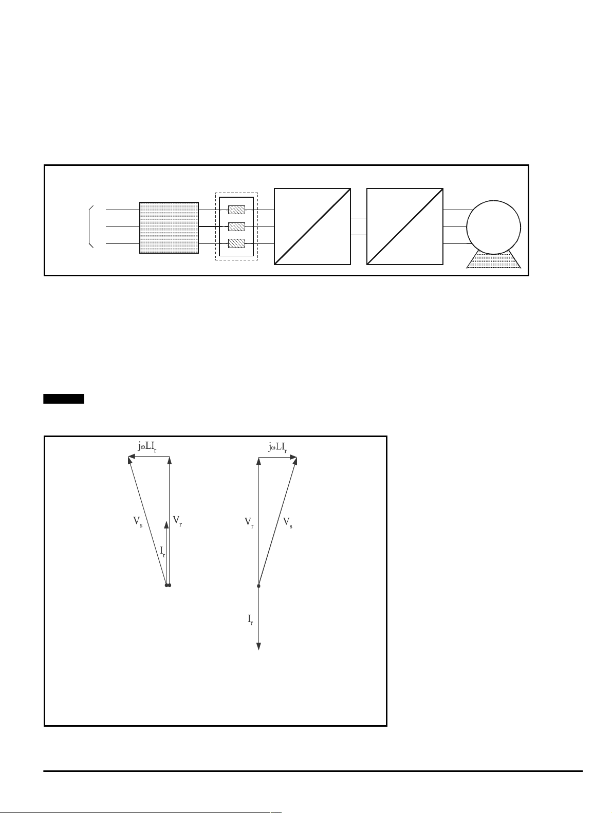
Figure1-1 Regen drivesystem connection
3Phase
Supply
Regen
Inductor
R
Y
B
Additional
Circuitry
U
V
W
egen Drive
AC
DC
+DC
-DC
Motoring Drive
DC
DC
AC
U
V
W
M
1.1 Principles of operation
The inputstage of a non-regenerative AC drive is usually an uncontrolled dioderectifier, therefore power cannot be fed back intothe AC mains
supply.
In the case of a Unidrive operating in Regenerative mode, the IGBT bridge is used as a sinusoidal rectifier, which converts the AC supply to a
controlled DC voltage.This DC voltage canthen be usedtosupply oneormore Unidrives whichcontrolmotors,commonlyknown as motoring drives.
A Regen drive produces a PWM output voltage which has a sinusoidal fundamentalatanamplitude andphase which are almost the same as those
of the AC supply voltage. The differencebetween thedrive PWM linevoltageandthesupplyvoltage occursacross theRegen drive’sinductors.This
voltage has a high frequency component which is blocked by the Regen inductor and a smallsinusoidal component at linefrequency.Asa result,
currents flowing in these inductors are sinusoidal with a small high frequency ripple component.
NOTE
T erminals L1, L2 and L3 and the associated diode rectifier are not connected and are redundant on drives used in a Regen configuration.
Figure 1-2 Phasor diagram
N
Power flowfrom supply Power flowback to supply
V
s
V
r
jωLI
I
r
Supply Voltage
Voltage at line terminals of Regen drive
Voltage across RegenInductor
r
Current at line terminals of Regen drive
UnidriveRegenInstallation Guide 1
Issue Number: 2 www.controltechniques.com
Page 6

1.2 Power flow
The phasor diagraminFigure 1-2 illustratesthe relationship between the supply voltage and the Regen drivevoltage. The angle betweenthe two
voltage vectorsis approximately 5° at fullload, givingapowerfactor which is nearunity.
The directionofthe power flow can bechanged relative tothesupply voltage, by makingsmall changes to theRegendrive outputvoltage andphase.
A fast transient response is achievedby means of a space vector modulator.
1.3 Advantages of Unidrive operating in Regen mode
The main advantages for an AC Regen system are:
• Energy saving
• The inputcurrent waveformissinusoidal
• The input current has a near unity power factor
• The output voltage for the motor can be higher than the available AC mains voltage
• The Regen drive willsynchronise to any frequency between30and100Hz, provided the supply voltage is between 380V-10% and 480V +10%
• Underconditionsof AC mains instability,a UnidriveRegen system cancontinuetofunction downtoapproximately150Vac supplyvoltage without
any effect on the DC bus voltage and hence on the operation of the motoring drives (increased current will be taken from the AC supply to
compensate up to the currentlimit of the Regendrive)
• The Regen and motoring drives are identical
2 Unidrive Regen Installation Guide
www.controltechniques.com Issue Number: 2
Page 7

2 Sizing of a Regen system
Refer to Appendix E Unidrive Regen specifications on page 44, for the specifications of the Unidrive Regen.
The sizing of a Regen system musttake into account the following factors:
•Linevoltage
• Motor rated current, rated voltage and power factor
• Maximum load power and overload conditions
In general, when designing a Regen system, equalRege n and motoring drive rated currents will work correctly. However, care must be taken to
ensurethat under worstcasesupply conditions theRegen drive is able to supply or absorballtherequired power. In multi-drive configurations, the
Regendrive must be of a sufficientsize to supply the netpeakpower demanded by thecombined loadofall the motoring drivesandthe drivelosses.
If the Regendrive is unabletosupply the fullpower required by the motoring drive, theDC busvoltage willdrop and in severe cases may lose
synchronisation with the mains and trip.Ifthe Regen drive is unable to regenerate the full powerfrom the motoring drive intotheDC bus, thenthe
Regen/motoring drive will trip on over-voltage.
The following are twoexamples of how the required ratings of a Regen drive can be calculated.
NOTE
The Regen drive’s current limits are set at 150% and are not adjustable.
In the caseofa 25A,UNI2403 operating in Regen mode from a 400V supply, and a UNI2403driving a 400V rated, 0.85 pf motor:
The rated power of the Regen drive is = √3 x Ratedcurrent x Supply voltage
The motoring drive can supply power = √3 x Rated current x Motor voltage x Powerfactor
When the motoring driveissupplying rated current to themotor, the Regen driveonlyneeds to provide14.7kW, plus drivelosses. The Regen drive
can supply 17.3kW at rated current, which is ample, in this case.
Conversely, in somecases, a Regen driveofthesame rating asthe motoring drive, may not be able to supply enough power, as the following
example shows:
Example
In the caseofa 156A,UNI4403 operatinginRegenmode, and a UNI4403drivinga 75kW, 400V, 0.95pf motor:
If the motoring drive is supplying 175% maximum current and the Regendrive has its380Vsupply at the lowerlimits of -10%(342Vac), then,atthe
Regencurrent limitof150%:
The Regen drive max. available power is = √3 x 150% x Rated current x Supply voltage
The motoring drive max.poweris = √3 x 175% x Rated currentx Motorvoltage x Power factor
The Regendrive is also required to supplytheRegen and motoring drive losses.However, t his Regen drive is onlycapable of supplying
approximately 138.6kW and therefore a drive of a larger current rating is required.
Due to the effects of increased DC bus capacitance, there is a limit to the number of motoring drives that can be supplied from a Regen drive. This is
true irrespective of the balance of power between the motoring drivesandtheRegen drive.
NOTE
If the system consists of one Regen Unidrive and morethanthree motoringdrives, ControlTechniquesTechnical SupportMUSTbeconsulted about
the design of the system.
N
= 1.73 x 25 x 400
= 17.3kW
= 1.73 x 25 x 400 x 0.85
= 14.7kW
=1.73x1.5x156x342
=138.6kW
=1.73x1.75x156x400x0.95
=179.7kW
N
UnidriveRegenInstallation Guide 3
Issue Number: 2 www.controltechniques.com
Page 8

3 Power connections
The following section covers the power connections required for Unidrive Regen systems. Note that with Unidrive Regen systems there are no AC
supply connectionsmade to L1, L2 or L3 driveterminals.
NOTE
For control circuitconnections refertoChapter 4 Control circuit connectionson page 8.
3.1 Overall system layout
The table below shows the key to the following system layout diagrams.
Table 3-1 KeytoFigure3-1andFigure3-2
V1, V2,V3 Varistor network 550V (linetoline)
V4, V5,V6 Varistor network 680V (linetoground)
N
E Ground connection point
RFI EMC filter
SFFL Switching frequency filter inductor
L regx Regen inductor
Rsx Softstart resistor
R-control Ribboncablestocontrolpod(Unidrivesize5only)
R-parallel Ribboncables between powermodules (Unidrive size5only)
Fsx ACsupply fusing
Fx ACRegenfusing(Unidrivesize5only)
SFF Cx Switching frequency filter capacitor
Rdx Switching frequency filter capacitor discharge resistor
Tcx Thermocouple
K1 Supply contactor
K2 Main contactor
K3 Auxiliary contactor
MCB1x Switching frequency filtercapacitorMCB
aux1x
aux2 Main contactorauxiliaryfor“main contactor closedsignal”
aux3 K3 auxiliary with coil supplyfor K2
Ovld Thermal, Magnetic overload
Switching frequency filter MCB auxiliary through which Regen drive enable is
connected
4 Unidrive Regen Installation Guide
www.controltechniques.com Issue Number: 2
Page 9
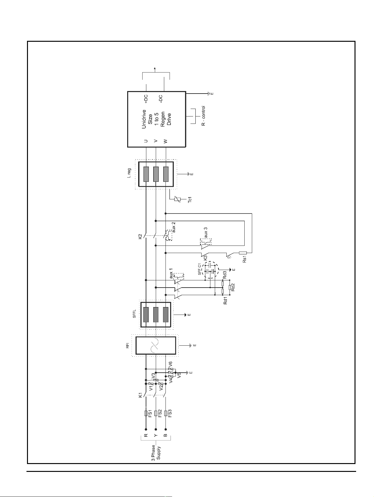
3.1.1 Standard single Regen, single/mul tip le m otoring system
Figure 3-1 Power connections: Single Regen
DC Bus to
Motoring
Drive(s)
Ovld
MCB1
UnidriveRegenInstallation Guide 5
Issue Number: 2 www.controltechniques.com
Page 10
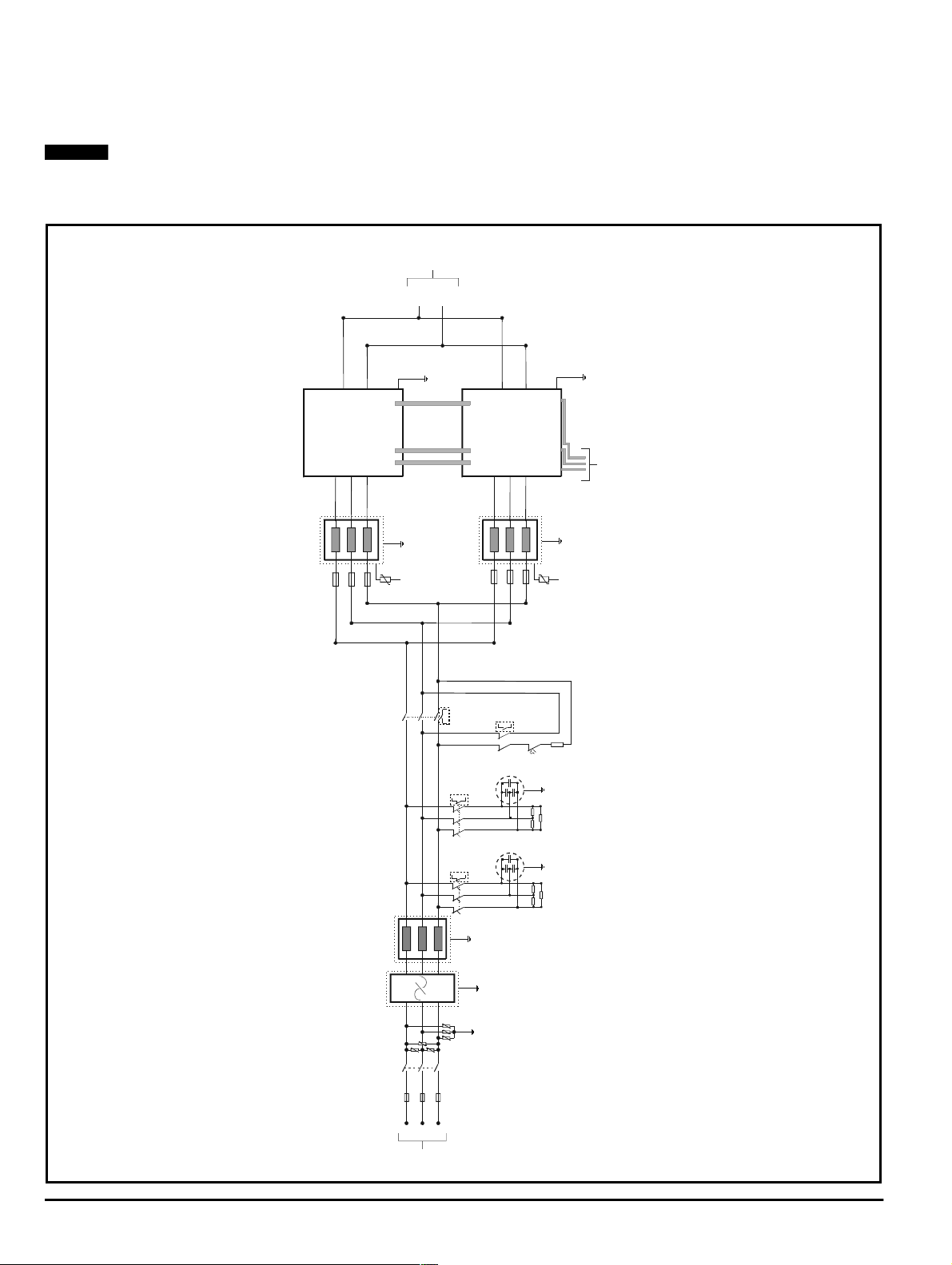
3.1.2 Standard multiple Regen, multiple motoring system
R - control
If the total power requirement istoogreat for one Unidrive size 5 Regen drivetosupply, more than one drive can be used.
OneRegensystem can consist of multiple Unidrive size5Regen drives,which can supply multiple Unidrive size5motoring drives, providing thatthe
totalload power doesnot exceed the rating of the Regen drives. See figure3-2for a dual size 5 Regen configuration.
NOTE
High power set-upsshould useUnidrivesize 5. This is the onlymodule whichis designedforparallelRegen operation.
For systemswith more thantwoUnidrive size 5 drives in parallel Regenoperation, contactCTTechnical Support.
Figure 3-2 Power connections: Unidrive size 5 multiple Regen
N
DC
Bus
Common
-DC
+DC
E
+DC
Size 5
Regen
Drive 1
Unidrive
U
V
W-DC
Lreg1
F1F2F3
R-parallel
E
Tc1
K2
SFFL
Lreg2
aux 2
aux 1b
MCB 1b
aux 1a
MCB 1a
E
-DC
+DC
Size 5
Regen
Drive 1
Unidrive
U
V
W
F4
F5
F6
aux 3
K3
Ovld
SFF C2
Rd6
Rd4
SFF C1
Rd3
Rd1
E
E
Tc2
Rs1
E
Rd5
E
Rd2
RFI
V3
V1
V2
K1
FS1
FS2
Y
R
Supply
3Phase
E
V6
V5
E
V4
FS3
B
6 Unidrive Regen Installation Guide
www.controltechniques.com Issue Number: 2
Page 11

3.2 Non standard configurations
There are a number of possible options available when designing a Unidrive Regen system depending on the user requirements and the nature of the
AC supply. Non standard systems can be created where favourable supply conditions exist, allowing cost and space savings to be achieved by
reducing the number of components.
3.2.1 Switching frequenc y filter
If the supply to the Regen driveisshared with other equipment, then it is strongly recommendedthat a switching frequency filter be incorporated in
order to avoid the risk of interference or damage to the other equipment.
3.2.2 Supply assessment
The following guidelines should be used when assessing whether or not a switchingfrequency filterisrequired.
Symbols used are:
Nominal drive 100% current rating.
I
Drive
I
Short circuit current of supply at pointofcoupling with other equipment.
SC
Ratedcurrent of supply.
I
Supply
The switching frequency filter may be omitted if the following relation is true:
I
Drive
I
SC
If the short-circuit currentisnot known,thenareasonableestimatecanbe madeifitisassumed that the fault currentof the supply is 20 times the
ratedcurrent.This is very commonly the case wherethe supplyisderived through a distributiontransformer from a higher voltage supply with a high
fault level.
Then:
I
Drive
I
Supply
This second relation is helpful but must be used with care. It is reliable where the Regen drive is supplied through its own cable run from a point close
to the distribution transformer terminals. If theRegen drive shares a long cablerunwith other equipment, thentheeffect of the cableimpedanceon
the faultlevel must be taken into account if a risk of disturbance to the other equipment is to be avoided.
This procedure will normally be applied when assessing a non-dedicated low-voltage supply. It may also be applied to the medium/high voltage
supplywhere the low-voltagesupply is dedicated to the drive.Inthatcase the currents used mustbe referred to the highvoltage side of the
transformer.
3.2.3 RFI filter
Whether or not an RFI filter is required is dependent upon the user requirements and the AC supply network. For further details refer to Chapter
7 Unidrive Regen EMC information on page 19. An RFI filter must not be fitted without a switching frequency filter present in the system.
1
<
140
1
<
7
UnidriveRegenInstallation Guide 7
Issue Number: 2 www.controltechniques.com
Page 12
4 Control circuit connections
All power circuit connections should be made as shown in Chapter 3 Power connections on page4.
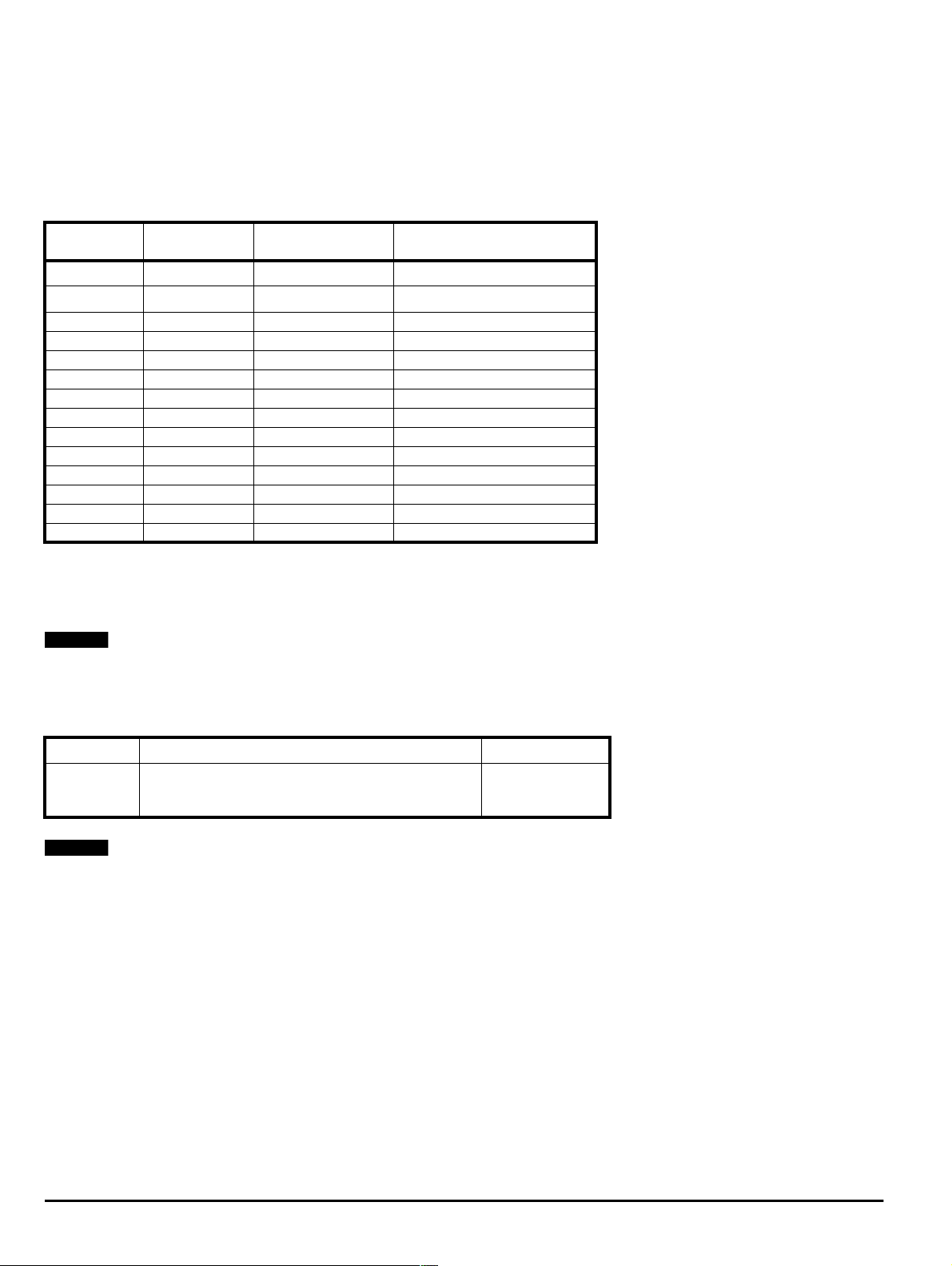
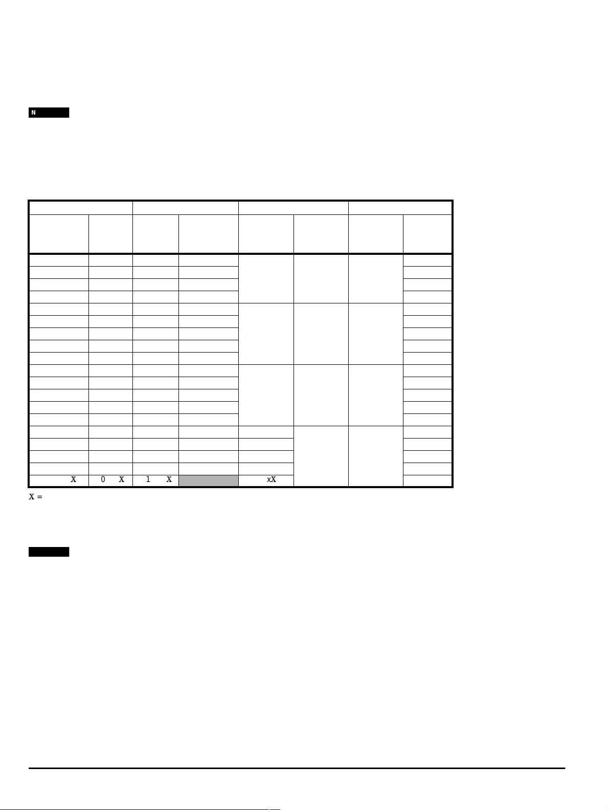
4.1 Digital / Analog I/O set-up in Regen mode
The following table lists the default functions of the analog and digital I/O on a Regen drive. The terminals which are listed as “Fixed” have dedicated
functions for Regen operation. They mustbe connected to perform their allocated functionandcannot be re-programmed.
Table 4-1 Functions of the analog and digital I/O
Terminal No.
1 Drive relay Fixed
2 Drive relay Fixed
5 Analog input1 User-programmable
7 Analog input2 User-programmable
8 Analog input3 User-programmable
9 Analogoutput 1 User-programmable Output- Supply current
10 Analog output 2 User-programmable Output - Supply power
24 Digital output 1 Fixed Not used
25 Digital output 2 Fixed Output - Enable other drive
26 Digital output 3 User-programmable Drivehealthy
27 Digital input 1 User-programmable Input - Reset
28 Digital input 2 Fixed Input - Main contactor closed
29 Digital input 3 User-programmable
30 Enable Fixed Enable
* Pr 8.25 must be setby theuser. See Table 4-2.
Terminal
Description
Fixed or
Programmable
Function in Regen Mode
Output - close auxiliary contactor*
Output - close auxiliary contactor*
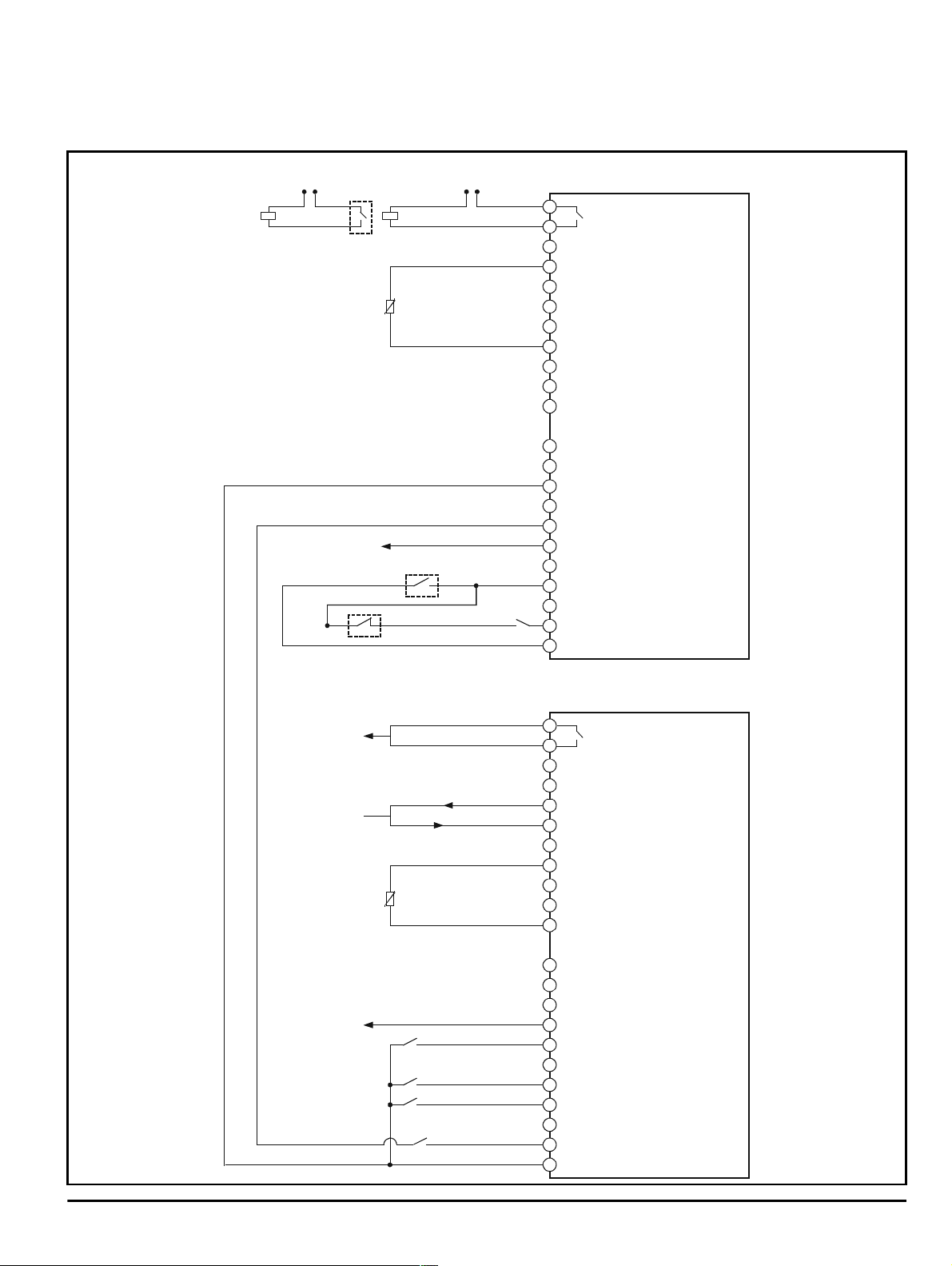
Figure 4-1 shows typical control connections for a Regenandmotoring drive. In this example the motoring drive is configured for 4-20mA Speed/
Torque reference and sequencing Mode 4 with Run Forward and Run Reverseinputs.
NOTE
All control connections for theRegen drive mustbe madeas shownin Figure 4-1.
The Regen drive healthy signal can be taken from digital output 3 on terminal 26 (if the Regen drive is disabled, trips, or detects that the mains supply
is lostthis output thenbecomes inactive).
Table 4-2 Configuration of drive relay
Pr8.25 -Relay
NOTE
Unidrive Regenhas beendesignedto operate innegativelogicasdefault.In orderfor thedrive to beconfigured tooperateinpositivelogicalterations
must be madetothecontrol connectionsand parameter settings (contact C.T. TechnicalSupport forthis information).
N
Parameter Description Drive
The Regen drives relay on terminal 1 and 2 has to be
Source
configured toclose theauxiliary contactoronpowerupand
remove the softstart circuit. Set Pr 8.25 to Pr 15.14
Regen drive
N
8 Unidrive Regen Installation Guide
www.controltechniques.com Issue Number: 2
Page 13
4.2 Regen inductor thermistors
0
A
A
0
0
D
D
2
D
2
D
2
D
2
D
3
E
3
0
M
0
A
A
A
A
A
1
A
1
0
2
0
2
+
2
0
2
D
2
D
2
D
2
D
2
D
2
D
3
E
3
0
M
Each of the Unidrive 3-phase Regen Inductors has a thermistor fitted; when the system consistsof multipleRegen drivesthethermistorsshould be
connected in series due to there only being a singlethermistorinput on the Regen drive.
Figure 4-1 Control connections - (negative logic configuration)
Externalpower supply
for K2 coil
External power supply
forK3coil
K2
aux3
Tc1
K3
1
2
3
VAnalog
4
10V Out
5
nalog I/P 1+
6
nalog I/P 1-
7
Analog I/P 2
8
Analog I/P 3
9
AnalogO/P 1
10
AnalogO/P 2
11
VAnalog
Relay NO
(Set Pr to
8.25
Pr )
15.14
Regen Drive
21
0V
22
+24V Out
23
V Digital
24
Drive
Healthy
aux2
aux 1x
Output enable
User
enable
25
6
7
8
9
0
1
igitalI/O 1
igitalI/O 2
igitalI/O 3
igitalI/P 1
igitalI/P 2
igitalI/P 3
nable
V Digital
Drive
Healthy
Speed/T orque Ref
4 - 20mA Current
Loop
otor Thermistor
At ZeroSpeed O/P
Reset
Fwd
Rev
User enable
1
2
3
VAnalog
4
10V Out
5
nalog I/P 1+
6
nalog I/P 1-
7
nalog I/P 2
8
nalog I/P 3
9
nalog O/P 1
0
nalog O/P 2
1
VAnalog
1
V
2
24V Out
3
V Digital
4
igitalI/O 1
5
igitalI/O 2
6
igitalI/O 3
7
igitalI/P 1
8
igitalI/P 2
9
igitalI/P 3
0
nable
1
V Digital
Relay NO
otoring Drive
UnidriveRegenInstallation Guide 9
Issue Number: 2 www.controltechniques.com
Page 14
5 Components
The following parts are required to assemble a Unidrive Regen system:
•Motoringdrive
• Regendrive
• Regeninductor
• Softstart resistor
• Contactors,MCBs and overload
• Switching frequency filter (optional)
• RFIfilter (optional)
•Varistors
• Fuses
NOTE
The Regen inductor and softstart resistor duty cycle is very arduous. Therefore, correct component selection is critical. The most sensitive aspects
are line-inductorlinearity, saturation currentand resistor-energypulse rating.Only inductorsandsoftstart resistors as specified in this Installation
Guide should be used.
5.1 Motoring drive
Unidrive in Open Loop,Closed Loop or Servomode. Any software version.
This controlsthemotor by convertingthe DC bus voltagetoa variable voltage, variable frequency supply. Power flowis betweenthe DC bus and the
motor. TherearenoACsupply connections.
5.2 Regen drive
Unidrive in Regen mode. (Must be software version 2.10.04 or higher).
The Regen drive converts the AC supply to a regulated DC voltage. It also provides bi-directional power flow and sinusoidal input currents.
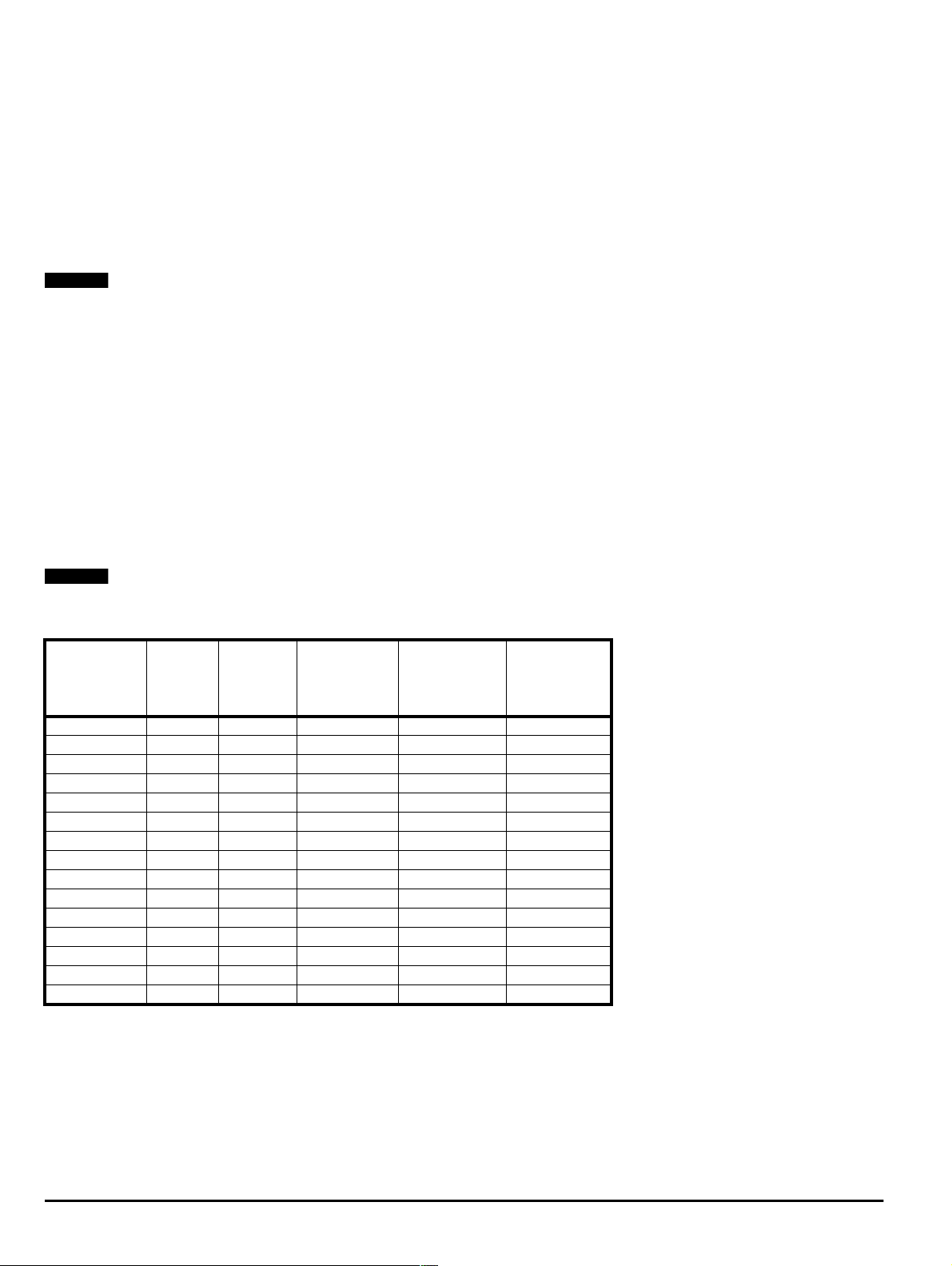
5.3 Regen inductor
The Regen inductor supports the difference between the PWM voltage from the Regen drive and sinusoidal voltage from the supply.
NOTE
Regen inductors are special parts. Under no circumstances must a part be used other than those listed in Table 5-1.
Table 5-1 3-phase Regen inductors
Drive Model
N
N
Rated
power
kW A rms mH
UNI 1405 4 9.5 6.3 1 4401-0001
UNI 2401 5.5 12 5.0 1 4401-0002
UNI 2402 7.5 16 3.75 1 4401-0003
UNI 2403 11 25 2.4 1 4401-0004
UNI 3401 15 34 1.76 1 4401-0005
UNI 3402 18.5 40 1.5 1 4401-0006
UNI 3403 22 46 1.3 1 4401-0007
UNI 3404 30 60 1.0 1 4401-0008
UNI 3405 37 70 0.78 1 4401-0009
UNI 4401 45 96 0.63 1 4401-0010
UNI 4402 55 124 0.48 1 4401-0011
UNI 4403 75 156 0.38 1 4401-0012
UNI 4404 90 180 0.33 1 4401-0013
UNI 4405 110 202 0.30 1 4401-0014
UNI 5401 160 300 0.24 1 4401-0015
Rated
current
Inductance
Number
requiredper
Regen drive
CT
part number
10 Unidrive Regen Installation Guide
www.controltechniques.com Issue Number: 2
Page 15
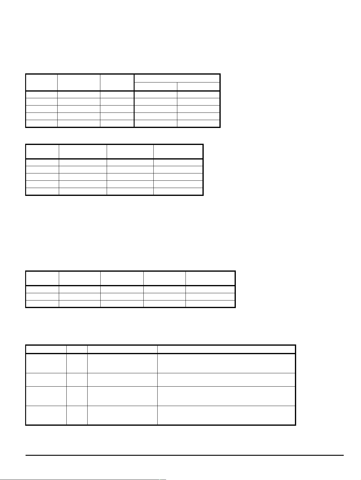
5.4 Softstart resistor
The start-up circuit limits the amountofcurrent flowing intothe DCbusoftheRegen driveandinto the motoring drives.
5.4.1 Single systems
The softstart resistor for singleRegen applications mustbeasspecifiedin the following table. Energyrating andoverload are non-standard and both
are important.
Table 5-2 Single Regen, single motoring, Unidrive size 1 to 5
Drive
size
1 1 150 1270-3157 150
2 1 150 1270-3157 150
3 1 48 1270-2483 48
4 2 24 1270-2483 48
5 2 24 1270-2483 48
Table 5-3 Softstart resistor data
Drive size Resistors Rms current
1 1270-3157 0.4 5
2 1270-3157 0.4 5
3 1270-2483 0.5 15
4 1270-2483 x 2 0.6 32
5 1270-2483 x 2 1.2 32
The above figures havebeencalculatedassumingapeak supply voltage of480Vac +10%.Refer alsoto AppendixBComponent Sizing Calculations.
Number of
parallel resistors
5.4.2 Multiple systems
In nonstandardcases,e.g. multiple motoring, multipleRegen systems, thesoft-start resistor sizeand ratingmust be recalculated due to thecharging
characteristics changing. For the method of calculating the new resistor size and rating, refer to Appendix B Component sizing calculations on
page 36.
5.4.3 Protection
Protection for the softstart circuit is provided using a thermal overload to protect against a high impedance short circuit, and a separate magnetic
overload to protectagainst a directshort circuit.For multiplesystems the softstartresistorsizemustberecalculated resulting in resizing of the
thermalmagnetic overload required. Refer to Appendix B Component sizing calculations on page 36.
Table 5-4 Thermal magnetic overload
Drivesize Rated CurrentARated Voltage
1 & 2 0.3 480 1 4133-0117
3 1 480 1 4133-0217
4 & 5 2 480 1 4133-0277
Totalvalue Resistors
Ω CT part number Value Ω
Charging current
Vac
A
Number of
Poles
A
CT part number
5.5 Contactors, MCBs and overload
Contactors and MCBs are required as follows:
Table 5-5 Contactors and MCBs
Function Ref Description Specification
3 pole NO + auxiliary NO
Main contactor K2
Auxiliary
contactor
Switching
frequency filter
MCB
Thermal
magnetic
overload
MCB 1x is fitted between the switching frequency filter capacitors and the AC supply. The MCB should have an auxiliary which the enable for the
Regen and motoring drive is connected through. This will act as a safe guard and prevent the system running with a fault on the switching frequency
filter. Also refertoAppendix B Component sizing calculations on page36.
contact. Coil voltage selected
to suit available supply.
K3 2 pole NC + auxiliary NO
MCB
3 pole + auxiliary NC
1x
Ovld Single pole
UnidriveRegenInstallationGuide 11
Issue Number: 2 www.controltechniques.com
Current ratingequal to totalcurrentrequirement.
Voltage rating equaltoAC mains supplyvoltage.
Coil mustnotexceed 240Vac5A resistiveload.
Installation category 1.
Currentrating sized to rms currentof switchingfrequency filter
capacitors andchargingcurrent at powerup.
(Refer to Table 5-6).
Sized to thesoftstart resistortoprotect thermally and
magnetically.(Refer to Appendix B Componentsizing
calculations on page 36).
Page 16
5.6 Switching frequency filter
The AC input terminals of a Regen drive produce a PWM output voltage, which has a sinusoidal component at line frequency, plus significant
harmonics at the switching frequency and its multiples.
This filter prevents switching frequency harmonic currents gettingbackinto the supply. If the filter is notfitted, the presence of currents in the kHz
regioncould cause supply problemsordisturbance to otherequipment.
NOTE
The switching frequencyfilter inductors needtobe rated to the totalcurrent requirement.
The followinginductorsarestandard 3-phase inductors(ratedatdrive ratedcurrentfora singleRegensystem or rated at total currentrequirementfor
multiple Regensystem), they carry only 50/60Hzcurrentwith a negligible amountof highfrequency current.
The capacitors specified below are suitable for operation at any switching frequency. These capacitors are sized for operation at 3kHz however
operation above 3kHz is possible with the capacitors being more effective.
Table 5-6 Switching frequency filter
N
Drive 3-phase inductor 3-phase capacitor MCB rating
Rated
Model
UNI 1405 9.5 3.160 4401-0162
UNI 2401 12 2.500 4401-0163 31
UNI 2402 16 1.875 4401-0164 36
UNI 2403 25 1.200 4401-0165 45
UNI 3401 34 0.880 4401-0166
UNI 3402 40 0.750 4401-0167 115
UNI 3403 46 0.650 4401-0168 124
UNI 3404 60 0.500 4401-0169 142
UNI 3405 70 0.390 4401-0170 160
UNI 4401 96 0.315 4401-0171
UNI 4402 124 0.240 4401-0172 262
UNI 4403 156 0.190 4401-0173 325
UNI 4404 180 0.165 4401-0174 348
UNI 4405 202 0.135 4401-0175 385
UNI 5401 300 0.100 4401-0176 80 (x1)
UNI 5402 600 0.050 4401-0177 80 (x2) 580
UNI 5403 900 0.034 4401-0178 80 (x3) 580
UNI 5404 1200 0.025 4401-0179 80 (x4) 580
UNI 540
current
AmH µFAA
X
300 x
Lfilt
X
0.100 /
CT part
number
X
Cfilt
5.7 1610 - 5752 2.1
24 1665 - 2244 15
48 1665 - 2484 25
80 (xX)580
CT part
number
1665 - 2804
rms
current
35 per
capacitor
Peak
current
28
106
252
580
X
= number of size 5 drives
5.6.1 Protection
An MCB shouldbefitted between the AC supplyand the capacitor.This is to protect thewiring betweenthecapacitorandthemainbus bar.
NOTE
For multiple Regen systems, refertoAppendix B Component sizing calculations on page 36 for sizing of the MCB.
N
12 Unidrive Regen Installation Guide
www.controltechniques.com Issue Number: 2
Page 17
5.7 RFI filter
E
In common withconventional drives, significantground currentsaregeneratedby the capacitance of the motorto ground, themotor cablesto ground,
and the drivepower circuits to t heir heatsinks.The RFIfilter willprovide a relatively shortr eturn path for ground currents back to the drivespower
circuit.
Table 5-7 RFI filter data
CT Model
Number
UNI1405 480 4 10
UNI2401 to 2402 480 7.5 16
UNI2403 480 11 25
UNI3401 to 3403 480 22 50 Book End 100 4200-6116
UNI3404 480 30 63 B ook End 100 4200-6117
UNI3405 480 37 100 Book End 100 4200-6106
UNI4401 to 4402 480 55 150 Book End 100 4200-6107
UNI4403 to 4404 480 90 180 Book End 100 4200-6111
UNI4405 480 110 220 BookEnd 100 4200-6112
UNI5401 480 160 300 BookEnd 100 4200-6115
Volts
Vac kW A m
Maximum
power
Filter
current
rating
Mounting style
Book End 100 4200-6105
Footprint or Book End 100 4200-6104
Book End 100 4200-6109
Footprint or Book End 100 4200-6108
Book End 100 4200-6114
Footprint or Book End 100 4200-6113
Motor
cable
length
CT part
number
Do not use an RFI filter without the specified switching frequency filter, as failure of the RFI filter will occur, due to the switching currents.
CAUTION
5.8 Varistors
AC line voltage transients can typically be caused by the switching of large items of plant, or by lightning strikes on another part of the supply system.
If thesetransientsare not suppressed, they cancause damagetotheinsulation of the Regen inputinductors,orto the Unidrive Regen drive
electronics.
Table 5-8 Varistors
Configuration
Line to line 1 to 5 550 400 Z500NS 3 2482-1501
Line to ground 1 to 5 680 450 Z680LNS 3 2482-0680
NOTE
Seven varistors are requiredwhen operating with an IT supplyas shown in Figure3-1 on page 5, Figure 3-2 on page 6 and Figure A-2 on page 32.
N
Drive
size
Varistor
voltage
Vac J
5.8.1 Configuration
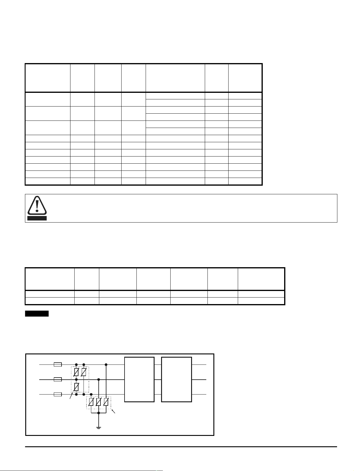
Varistors should be fitted after the supply fuses, as shown in Figure 5-1:
Figure 5-1 Fitting of Varistors
Fuses Varistors
R
Y
B
550Vac
varistors
680Vac
varistors
RFI
Filter
Varistor
energy
Type number Quantity CT part number
Switching
Frequency
Filter
UnidriveRegenInstallationGuide 13
Issue Number: 2 www.controltechniques.com
Page 18
5.9 Fusing
RegenInductor
+DC-DC+DC-DCUVW
RegenDriveMotoringDrive
DCBusFusing
RegenInductor+DC-DC
+DC-D
C
+DC-DCUVW
RegenDriveM
o
D
M
o
D
Fusing for the Regen systemis requiredinorder to protectthefollowing:
• Supply transformer
• Supply cables
• Regeninductor
• Regendrive
•Motoringdrive
In the event of failure, the fusing will prevent fire by limiting the amount of energy allowed into the Regen and motoring drive units. The AC supply
fusingshouldberatedtotheRegensystem’scontinuousratedcurrent.TheRegenACfusingwhenusedwitheachmultiplesize5Regendrive
should be ratedtothe 450Acontinuousrated currentof the drive. The +
motoring driveratedcurrent and >
750Vdc.
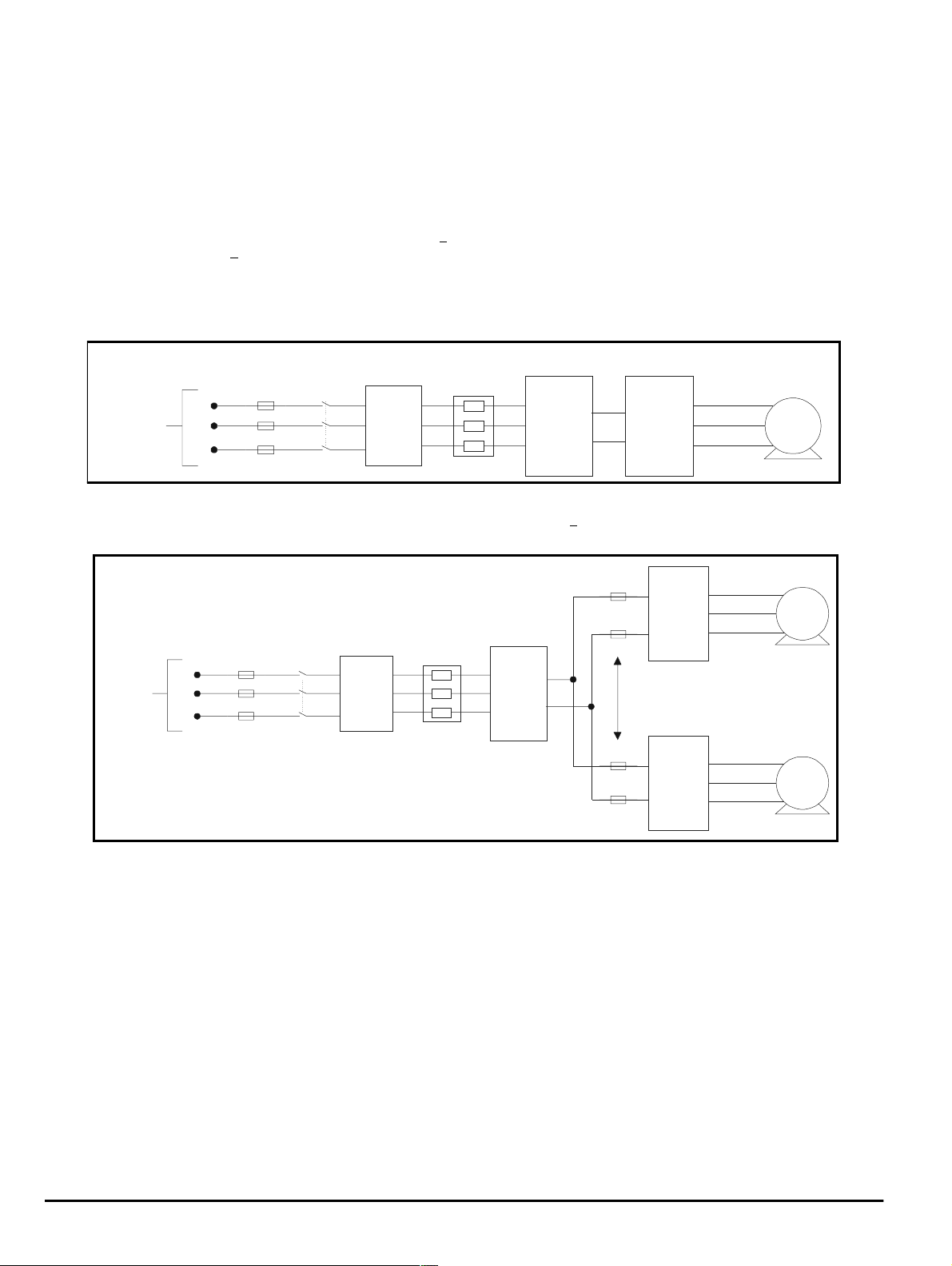
5.9.1 Standard systems
FusingforastandardRegen system,single Regen plussingle motoring drive (both drives of the same rating)should consistofACsupply fusingas
shown below:
Figure 5-2 Fusing: Standard systems
DCbusfusingwhenusedwithmultiplemotoringdrivesshouldberatedto2x
3 Phase
Supply
AC
Supply
Fusing
R
Y
B
Main
Contactor
Additional
Circuitry
U
V
W
M
5.9.2 Multiple size 1 to 4 motoring drives
When a Regensystem consists of multiplesize 1 to 4 motoringdrives, AC supplyfusing and +DCbusfusingshouldbefittedasshownbelow:
Figure 5-3 Fusing: Multiple size 1 to 4 motoringdrives Regen system
toring
rive
U
3Phase
Supply
V
AC
Supply
R
Fusing
Y
Main
Contactor
Additional
Circuitry
W
B
toring
rive
U
V
W
M
M
14 Unidrive Regen Installation Guide
www.controltechniques.com Issue Number: 2
Page 19

5.9.3 Multiple size 5 Regen
M
DCBusFusingRegenACFusin
g
+DC-DCUVW+DC-DCUV
W
MotoringDriveMotoringDriv
e
When a Regensystem consists of multiple size 5 Regen andmotoring drives, AC supplyfusing and -DC bus fusing should be fitted as shownbelow:
Figure 5-4 Fusing: Multiple size 5 Regen system
3 Phase
Supply
Regen
Inductor
AC
Supply
R
Fusing
Y
Main
Contactor
Additional
Circuitry
Regen
Drive
U
+DC
V
W
-DC
B
Regen
Drive
U
+DC
V
-DC
W
Regen
Inductor
Output
Sharing
Choke
Output
Sharing
Choke
UnidriveRegenInstallationGuide 15
Issue Number: 2 www.controltechniques.com
Page 20

6 Important considerations
6.1 Fundamentals
6.1.1 You must
• UseRegen inductors of the correct type and value,as specified.
• Usea start-up resistor of the correcttype and value,asspecified.
• Connect the Regendrive outputenable signal to the enableinput on the motoring drive(s).
• Use a switching frequency filter if an RFI filter is present or the AC supply is not dedicated solely to the Regendrive.
• Fitfuses where specified,andensure they are of thecorrect rating.
• Ensure that the cubicle is correctly sized andventilated, taking into accountthelosses generated by all of thecircuit components.
6.1.2 You must not
• Connect a circuitofanytype between a Regenandmotoring drive’s DC bus.
• Attempt to use a Unidrive size 1-4 Regen in parallel configuration (only Unidrive size 5 Regen can be used in parallel configuration).
6.2 Unidrivesize3and4
If a Unidrive size 3 or 4 of anyothervariantexcept the Regenvariant istobe usedin a Regen system,aninternalmodificationisrequiredtoboth the
Regen and motoring drive(s).
Damage to the drive(s) will result if this modification is not carried out.
CAUTION
NOTE
Modification of the drive must only be carried out by CT authorised personnel. If any details are required,contact C.T. Technicalsupport.
N
6.3 Ventilation
When designing a RegenSystem, considerations must be made fortheadditionalventilation requirements due to the introduction of the Regen and
Switching Frequency filter inductors.
The inductors have normal operating temperatures of approx. 150°C depending upon the ambient and the motor cable lengths. Care must
be taken so that this does not create a fire risk.
CAUTION
A Regen System can operateinanambient temperaturerange of 0°C to 50°C (32°F to 122°F) forUnidrivesizes 1 to 5. An output currentderating
must be applied with ambient temperatures between 40°C and 50°C. For derating figuresseetheUnidriveSize1to5UserGuide.
Ventilation for both the Regen and motoring drives in the system should be as specified in the UnidriveSize1to 5 User Guide.Providedthe
maximum cablelengthsin Table 6-3 onpage 18 havenotbeen exceeded, natural airflowventilationthrough theRegen and switching frequencyfilter
inductors is adequate. In special conditions, where themaximum cablelength (refer to Table6-3 on page 18) has been exceeded, forcedcooling
should be introducedf or the Regen Inductora s specif ied in Appendix C Long cableson page 41.
When sizingthe cubicle(s)for the Regen systemconsiderations mustbe madeforthe systems losses.
System Losses Documented In...
RFI Filter
Regen drive
Motoring drive
Control Module, Unidrive size 5
PowerModule, Unidrive size 5
UnidriveSize1to5UserGuide
16 Unidrive Regen Installation Guide
www.controltechniques.com Issue Number: 2
Page 21

Table 6-1 3-phase Regeninductor
Drive size
UNI 1405 9.5 6.3 1 4401-0001 125
UNI 2401 12 5.0 1 4401-0002 146
UNI 2402 16 3.75 1 4401-0003 175
UNI 2403 25 2.4 1 4401-0004 210
UNI 3401 34 1.76 1 4401-0005 285
UNI 3402 40 1.5 1 4401-0006 310
UNI 3403 46 1.3 1 4401-0007 320
UNI 3404 60 1.0 1 4401-0008 345
UNI 3405 70 0.78 1 4401-0009 415
UNI 4401 96 0.63 1 4401-0010 515
UNI 4402 124 0.48 1 4401-0011 585
UNI 4403 156 0.38 1 4401-0012 645
UNI 4404 180 0.33 1 4401-0013 775
UNI 4405 220 0.30 1 4401-0014 845
UNI 5401 300 0.24 1 4401-0015 1760
Table 6-2 3-phase switching frequency filter inductor
Drive size
UNI 1405 9.5 3.160 1 4401-0162 28
UNI 2401 12 2.500 1 4401-0163 35
UNI 2402 16 1.875 1 4401-0164 37
UNI 2403 25 1.200 1 4401-0165 40
UNI 3401 34 0.880 1 4401-0166 52
UNI 3402 40 0.750 1 4401-0167 60
UNI 3403 46 0.650 1 4401-0168 60
UNI 3404 60 0.500 1 4401-0169 80
UNI 3405 70 0.390 1 4401-0170 90
UNI 4401 96 0.315 1 4401-0171 100
UNI 4402 124 0.240 1 4401-0172 110
UNI 4403 156 0.190 1 4401-0173 130
UNI 4404 180 0.165 1 4401-0174 170
UNI 4405 220 0.135 1 4401-0175 180
UNI 5401 300 0.100 1 4401-0176 220
UNI 5402 600 0.050 1 4401-0177 400
UNI 5403 900 0.034 1 4401-0178 530
UNI 5404 1200 0.025 1 4401-0179 700
Rated current Inductance
A rms mH W
Rated current Inductance
A rms mH W
No perRegen
Drive
No perRegen
Drive
CT
part number
CT
part number
Total
losses
Total
losses
6.4 Cable length restrictions
There are 3 significant cable lengths which must be taken into account when designing a Regen system. Refer to Figure 6-1 on page 18.
6.4.1 AC supply conne ction
A is the AC cable length between the Regen inductor and the Regen drives terminals.
In general, no specialprecautions are necessary for the AC supplywiring in respect to the Regendrive. However the voltage in the wiring between
the Regen inductor and the Regen drive terminals is a source of radio frequency emission. To minimise emissions, these cables should be kept as
shortas possible. Ideally, the inductors should be mounted closetothedrive terminals.
If it is necessary to use a cable longerthan 5m, a screened cable should be used with the screen grounded as shown inFigure 6-1 on page 18.
6.4.2 DC bus connection
B is the DC bus connection between the Regen and motoring drive, the + DC bus connections between the drives should be treated as a single two
core cableandnott wo individualcable / bus bar lengths.
The DC poweroutput from theUnidrive which is used as the inputstage to the motoring drive(s) carries a common-mode high frequency voltage
comparable withtheoutput voltage from a standard drive. Allprecautionsrecommended for motor cablesmust also be appliedtoallcables
connected to this DC circuit.
UnidriveRegenInstallationGuide 17
Issue Number: 2 www.controltechniques.com
Page 22

If it is necessary to use a cable longer than 5m, a screenedcable should beusedwith the screengrounded as showninFigure 6-1.
RBYE
E
6.4.3 Motor connection
C is the AC cable length between the motoring drive and the motor.
Figure 6-1 Calculating the cable length of the Regen system
B
Regen
Drive
L1L2L3 WVU
E E
A C
Regen
Inductor
-DC
+DC
E
E
E
Motoring
L1L2L3 WVU
Motor
Drive
+DC
-DC
E
6.4.4 Maximum cable l eng th
The sum total length of the DC bus and motor cables (B and C in Figure 6-1)must not exceedthe values showninthetable below:
Table6-3 Cablelengths
Regen drive size
14 50
25.5-11 100
3 15 - 37 200
445-110 200
5 132 200 per Regen drive
Power rating Maximum cable length
kW m
If the cablelength in the abovetable is exceeded, additi onal components are required. Referto Appendix C Longcables on page 41.
18 Unidrive Regen Installation Guide
www.controltechniques.com Issue Number: 2
Page 23

7 Unidrive Regen EMC information
7.1 Immunity
Theimmunityof theindividual drivemodulesisnot affected byoperationin the regenerativemode.See driveEMC data sheets forfurtherinformation.
This Guide recommendstheuse of varistors between the incoming AC supply lines. These are strongly recommendedtoprotect thedrive from
surgescaused by lightning activityand/ or mains supply switching operations.
Since the regenerative input stage must remain synchronised to the supply, there is a limit to the permitted rate of change of supply frequency. If rates
of change exceeding 100Hz/s are expected then C.T .Technical Support should be consulted. This would only arise under exceptional circumstances
e.g. where the power system is suppliedfrom an individual generator.
7.2 Emission
Emissionoccurs over a wide range of frequencies.The effects are dividedinto three maincategories:
• Low frequency effects, such as supply harmonics and notching
• High frequency emission below30MHz where emissio n is predominantly by conduction
• High frequency emission above 30MHzwhere emissionis predominantly by radiation
7.3 Dedicated supplies
The natureofthe mains supplyhasanimportant effectontheEMCarrangements.For a dedicated supply, i.e. one whichhasnoother electrical
equipment fed from the secondary of its distribution transformer, normally neither an RFI filter or a switching frequency filter are required. Refer to
section3.2.2 Supply assessment on page 7.
7.4 Other supplies
Wherever otherequipment shares the samelowvoltagesupply, i.e. 400Vac, careful considerationmust be giventothelikelyneedforboth switching
frequency and RFI filters, as explained in section 7.7 Switching frequency emission and section 7.8 Conducted RF emission .
7.5 Supply voltage notching
Because of the use of input inductors and an active rectifier the drive causes no notching - but see section 7.7 Switching frequency emission for
adviceon switchi ng frequency emission.
7.6 Supply harmonics
When operated from a balanced sinusoidal three-phase supply, the regenerative Unidrive generates minimal harmonic current.
Imbalance between phase voltages willcausethe drive to generate some harmonic current. Existingvoltageharmonicsonthepower system will
cause some harmonic current to flow from the supply into the drive. Note that this latter effect is not an emission, but it may be difficult to distinguish
between incoming andoutgoingharmoniccurrent in a site measurementunlessaccuratephase angledata is availablefor theharmonics.No general
rule can be givenforthese effects, but the generated harmonic current levelswill always be smallcomparedwiththose causedby a conventional
drive with rectifier input.
7.7 Switching frequency emission
The Regendrive uses a PWM technique to generate a sinusoidalinput voltagephase-locked to the mainssupply. The input current theref ore
contains no harmonics of the supply unless thesupply itself contains harmonics or is unbalanced. It doeshowever contain current at the switching
frequency and itsharmonics,modulatedbythe supply frequency. For example, witha 3kHzswitching frequencyand50Hz supplyfrequency there is
current at 2.95, 3.15,5.95, 6.05kHzetc. The switching frequency is not related to that of the supply, so the emission will not be a true harmonic - it is
sometimes referred to as an “interharmonic”. The possible effect of this current is similartothat of a high-orderharmonic, and it spreads throughthe
powersystemina manner depending on theassociatedimpedances.T he internal impedance oftheRegen driveis dominatedby the seriesinductors
at the input.The voltage produced at switching frequency at the supply point is therefore determined bythepotentialdivideraction of the series
inductors and the supply impedance; section3.2.2 Supply assessment on page 7 gives guidelines to help in assessing whether a switching-
frequency filter is required. In case of doubt,unless the driveoperatesfromadedicated supply not shared with otherloads, it is strongly
recommended that the filterbefitted.
Failure to fit a switching frequencyfilter may result in damage to other equipment, e.g. fluorescentlight fittings, powerfactor correction
capacitors and RFI filters.
CAUTION
7.8 Conducted RF emission
Radiofrequency emission in the frequency rangefrom 150kHz to 30MHzismainly conducted out of the equipment through electrical wiring. It is
essentia l for compliance withall emissionstandards,except forIEC61800-3second environment, that the recommendedRFI f ilter and a shielded
(screened) motor cable are used.Most types of cablecan be used providedit has an overall screen. For example, the screenformed by the
armouring of steel wired armoured cable is acceptable. The capacitance of the cable forms a load on the drive and should be kept to a minimum.
UnidriveRegenInstallationGuide 19
Issue Number: 2 www.controltechniques.com
Page 24

When an RFI filter is used the switching frequency filter discussed above must also be used. Failure to observe this may result in the RFI
filter becoming ineffective and being damaged.
CAUTION
When used with the recommended filters, the Regendrive systemcomplies with the requirements for conductedemissionin thefollowingstandards:
Table 7-1 Requirements for conducted emission
Motor cable length (m)
1.5 I
100 I
Key to
table
I
1 The first environment is one where the low voltage supply network also supplies domestic premises
2 Restricted distribution means thatdrives areavailableonly to installers withEMCcompetence
For installation in the “second environment”, i.e.where the low voltage supply network doesnot supply domestic premises, no filterisrequiredin
ordertomeetIEC61800-3 (EN61800-3):1996.
Standard Description
EN50081-2
EN61800-3
IEC1800-3
Generic emission standard
for the industrial
environment
Productstandard for
adjustable speed power
drive systems
Switching frequency (kHz)
3
Frequency
range
0.15 - 0.5MHz
0.5 -30MHz
Inputcurrent >25A:Requirements for thefirstenvironment
Inputcurrent<25A: Requirements forthe firstenvironment
Limits Application
79dBµV quasi peak
66dBµVaverage
73dBµV quasi peak
60dBµVaverage
Unrestricted distribution
distribution
AC supply lines
1
:
2
: Restricted
Operation without a filter is a practical cost-effective possibility in an industrial installation where existing levels of electrical noise are likely
to be high, andany electronic equipment in operation has been designed for such an environment. Thereis somerisk of disturbance to
otherequipment,and inthis case theuser andsupplierof the drive systemmust jointlytakeresponsibilityfor correctingany problemwhich
CAUTION
occurs.
7.8.1 Recommended RFI filters
These are the same filters as recommended for standard (non-regenerative) operation:
Table 7-2 Recommended filters
Drive
UNI 1405
UNI 2401 - 2402 4200-6109
UNI 2403 4200-6114
UNI 3401 - 3403 4200-6116
UNI 3404 4200-6117
UNI 3405 4200-6106
UNI 4401 - 4402 4200-6107
UNI 4403 - 4404 4200-6111
UNI 4405 4200-6112
UNI 5401 4200-6115
Motor cable
length m
100
RFI filter:
C.T.part number
4200-6105
7.8.2 Related produc t standards
The conducted emission levelsspecifiedin EN50081-2areequivalent to the levelsrequiredby thefollowingproduct specific standar ds:
Table 7-3 Conducted emission from 150kHz to 30MHz
Generic standard Product standard
EN50081-2
EN55011 Class A Group 1
CISPR 11 Class A Group 1
EN55022 Class A
CISPR 22 Class A
Industrial, scientific and medical
equipment
Informationtechnology
equipment
20 Unidrive Regen Installation Guide
www.controltechniques.com Issue Number: 2
Page 25

7.9 Radiated emission
Radio frequency emission in the frequency range from 30MHz to 1GHz is mainly radiated directly from the equipment and from the wiring in its
immediate vicinity. Operation in regenerative mode does not alter the radiated emission behaviour, and the EMC data sheet for the individual
Unidrives used should be consulted for further information.
NOTE
Theoretically the use of two drives physically close together can cause an increase in emission level of 3dB compared with a single drive, although
thisisusuallynot observed in practice. All Unidriveshavesufficient margin in respect of thegenericstandardfor theindustrialenvironment EN500812 to allow forthis increase.
N
7.10 Wiring guidelines
The wiring guidelines provided for the individual drives alsoapply to regenerative operation,except thattheswitchingfrequency filter must be
interposed between the input drive and the RFI filter. The same principles apply, the most important aspect being that the input connections to the RFI
filtershould be carefully segregatedfromthe power wiring of the drives which carriesa relatively high “noise”voltage.
7.11 Multi-drive systems
It is common for regenerative drive systems to be constructed using numbers of drives with a single input stage, or other more complex
arrangements.I t is generallynotpossibleto laydownspecificEMCrequirements for suchsystems, sincethey are too largeforstandardisedtests to
be carriedout. In many cases the environmentcorresponds to the “secondenvironment” as described in IEC61800-3, in which case no specific limit
to conducted emission is required.National legisla tion such asthe European UnionEMCDirectivedoes not usuallyrequire thatcomplex installations
meet specific standards, but onlythat they meettheessential protectionrequirements, i.e.not to cause or sufferfrom electromagnetic interference.
Where the environment is known to include equipment which is sensitive to electromagnetic disturbance, or the low voltage supply network is shared
withdomestic dwellings,then precautions should be takento minimiseconductedradio frequency emission by the useofafilter at the systempower
input. For current up to 300A the Control Techniques filters listed previously are suitable.
For currents exceeding300Aup to 2400A suitable filters are available from thefollowing manufacturers:
Siemens B84143.A250.S(range up to 2500A)
Schaffner FN3359-300-99 (range up to 2400A)
These filters may not give strict conformity with EN50081-2, but in conjunction with the relevant EMC installation guidelines they will reduce emission
to sufficiently low levels to minimise the risk of disturbance.
UnidriveRegenInstallationGuide 21
Issue Number: 2 www.controltechniques.com
Page 26

8 Parameter descriptions
Key to parameter codes:
ô
ð
RW Read/Write
RO Read Only
Bit Two stateonlyparameter,0or1.
Bi Bipolar - can have positive and negative values.
Uni Unipolar - can have positive values only.
Txt Parameter value is represented on the display with strings of Text.
P ParameterisProtectedfrom beingcontrolledbyprogrammable inputs
Notethatthe equivalent Menu 0 parameter appears in the box preceding the parameterdescription.
8.1 Menu 15: S inusoidal rectifier
A Unidrive can be used as a sinusoidal input current powerunit to supplyoneormore Unidrives via their DC buses. When this mode is selected as
the drive type, menu 15 appears. This menu is used to set up the Unidrive. At the same time, menu 0 defaults to showing Pr 15.01 to Pr 15.13asPr
0.11 to Pr 0.28.
Range of values
Default value
and functions.
15.01
ô
This parameter gives the rms phasecurrent fromthesupply. Thesinusoidal rectifier controls the currentsothatthe fundamental current and voltage
are in phase at the power terminals of the drive. There is a small phase shift across the input inductors, and so the current magnitude and the real
component ofcurrentare approximatelyequal.Ifpower isflowing intothesinusoidalrectifierthe currentmagnitudeisnegative,andif poweris flowing
out (back into the supply) the current magnitude is positive.
15.02
ô
When the sinusoidal rectifier unit is active the supply voltage is given by this parameter. If the unit is not active this parameter shows zero.
0.11 Supply current magnitude
± Maximum drive current
0.12 Supply voltage
0to528
ð
ð
AROBi P
Vac RO Uni P
15.03 0.13 Supply power
± Drive max. current x 5.09 x √3/1000
ô
T otalsupply power of the drive is calculated from the product of the line voltage and current which is equivalent to 15.01 x 15.02x √3. Note that as the
powerfactor is approximately unity the powerisequal to the volt-amperes. The power shownis that flowing out of the drive, hence whenpower is
flowing from the supplytotheRegen drivePr 15.03 is negative, and when power is flowing from the Regen drive back into the supply Pr 15.03 is
positive.
ð
kW RO Bi
15.04 0.14 DC bus voltage
ô
Voltage at the DC output of the drive.
15.05
ô
When the sinusoidal rectifier unit is active this parameter givesthesupply frequency. P ositive values indicate positivephase sequence andnegative
values indicatenegative phasesequ ence. If the unit is not active this parameter shows zero.
0to830
0.15 Supply frequency
±100
ð
ð
Vdc RO Uni P
Hz RO Bi P
22 Unidrive Regen Installation Guide
www.controltechniques.com Issue Number: 2
Page 27

15.06
0.16 Input inductance
ô
At power-up this parameter is zero. Each time the unit is enabled the supply inductance is measured and displayed by this parameter. The value
given includes the supply inductance and the inductors inserted at the supply to the sinusoidal rectifier unit. The value given is only approximate, but
willgiveanindication as to whether the input inductance is correct for the sinusoidal rectifier unitsize.
15.07
ô
The sinusoidal rectifier unit will attempt to hold the DC bus at the level specified by this parameter. The higher the bus voltage the better the
performanceof the unit as there willbemorevoltage availabletocontrol theinput current. The bus voltage must always be higher than thepeakof
the line to line supply voltage if the unit is to operate correctly. T he voltagecanbeset to a levelupto800V,but this only leaves 30Vheadroom below
the over-voltage trip level.Thereforeit is bestto use the defaultvalue of700Vunless the supplyvoltageissuch that itmustberaised above thislevel.
Supply voltage
15.08
ô
This parameter sets the PWM frequency and also determines the sample frequency for loops.
The sampling frequency of the control system is based on the switching frequencies as follows:
Current control
DC bus voltage control and synchronisation with the supply
0.001 to 100
ð
0.17 DC bus voltage set-point
0to800
Minimum
Vac
380 650 700 800
415 680 700 800
480 780 780 800
Vdc
700 Vdc RW Uni
ð
0.18 Switching frequency
0 to 4: [3, 4.5, 6, 9, 12]
Switching frequency
kHz
3 3
4.5 4.5
66
94.5
12 6
Switching frequency
kHz
3 3
4.5 2.25
63
92.25
12 3
0:[3kHz] kHz RW Txt P
ð
mH RO Uni P
Recommended
Vdc
Control frequency
kHz
Control frequency
kHz
Maximum
Vdc
15.09
ô
Setting this parameter to 1 modifies the IGBT switching pattern so as to reduce the number of switching events. This has the following effects:
• Slightly reduced power loss in the Regen drive.
• Increased acoustic noisefrom input inductors.
0.19 High stability space vector modulation
0~1
0 RW Bit
ð
UnidriveRegenInstallationGuide 23
Issue Number: 2 www.controltechniques.com
Page 28

15.10
0.20 Quasi-square operation select
0.21
0.22
0~1
Sinusoidal rectifier synch ronising
0~1
Sinusoidal rectifier synch ronised
0~1
ô
The rate at which the DC bus voltage can be reduced by the drive depends on the headroom between the bus voltage and the supply voltage. If
quasi-square mode is selected this headroom can be effectively increased at some points within a supply cycle. This can give better performance,
particularly when the supply voltage is high or the bus voltage set-point is low.
15.11
ô
When the drive is enableditmustdetect thephase and frequencyof the mains. During this period this bit is set.Oncesynchronisationhas been
completed successfully this bit is cleared. If the supply is very severely distorted or a phase is missing the drive will repeatedly attempt to synchronise
untilitisdisabled or synchronisation is completed.
15.12
ô
Whenthedrive has beenenabled andsuccessfully synchronisedthis bit willbeset to 1. If the drive isdisabled,theunit tripsordetects thatthemains
is lost,this bit will besetto0.
0 RW Bit
ð
ð
ð
RO Bit
RO Bit
15.13 0.23 Sinusoidal rectifier phase loss
ô
If a supply phase is not presentthesinusoidalrectifier unit will not synchronisewhenitisenabled.However,if a phase is lost after synchronisation
one of thefollowing will occur:
• Lightly loaded: the unit will continue to operate normally.
• Medium load: the unit will continue to operate, but the phase loss bit is set.
• Heavyload: the unit will detect mainsloss,disable itselfandattempt to re-synchronise.
0~1
ð
RO Bit
15.14
ô
When the Regen drive has powered up through the soft start resistor and the DC bus voltage stabilised this bit will change from 0 to 1. This bit must
be routed to a digital output terminal which is used to energise the soft start contactor coil.
15.15
ô
When the close contactor output goes active the soft-start contactor should operate and short out the soft-start resistor. This bit should be set as the
destinat ion parameter foradigital inputconnected to anauxiliarycontacton the soft start contactor. If this inputbecomes inactive whenbit Pr 15.14 is
set then after a 100ms (approx.) delay the drive will inhibit so as to protect the soft-start circuit.
0.24
0.25
Close soft start contactor
0~1
ð
Soft start contactor is closed
0~1
ð
RO Bit
RO Bit
15.16 0.26 Enable motor drive
ô
When theunit has been enabledandsuccessfully synchronisedt his bit willbesetto1. If the Regendrive isdisabled,theunit trips or detects that the
mainsislost, this bitwill set to 0.
This bit should be routed to a digital output and used to enable the motoring drive(s) connected to the DC bus of theRegendrive.
0~1
ð
RO Bit
24 Unidrive Regen Installation Guide
www.controltechniques.com Issue Number: 2
Page 29

15.17
0.27
Line synchronisation trip enable
0.28
0~1
Line synchronisation status
0~5
ô
When the drive is enabled and the main contactor is closed it will try and synchronise the line supply. If this bit is 0 then the drive will continue to try
and synchronise to thelinecontinuallyuntil disabled, even if it does notsynchronisesuccessfully. If this bitis setto a 1 and the drive hasnot
successfully synchronised after trying for 30 seconds then the drive will trip ‘LI.SYNC’.
15.18
ô
This parameter is the linesupply synchronisation status. It is intendedtogivesome diagnostic information ifthe drivef ails to synchronisetothe
supply. If no attempt to synchronise to the supply has been made sincethedrive was switched on, if the driveissynchronised to the supply and
running, or if it has been running then this parameter will show ‘SYNC’. If the drive can not synchronise to the supply then this parameter will show the
reason why synchronisation failed. If the drive does fail to synchronise to the supply the most likely reasons are that the supply is very distorted, or
there are large voltage notches / spikes on the supply.
0SYNCSuccessfullysynchronised to linesupply
1PhDetFailed to correctly detect the phasing of the supply
2FrLoLine frequency too low
3FrHiLine frequency too high
4PLLOIOver current during final synchronisation of PLL to supply
5PLLPhPhasing error duringfinal synchronisation of PLL to supply
0 RO Bit
ð
ð
RO Txt P
15.19 Current control proportional gain
ô
0to30,000
110 RW Uni
ð
15.20 Current control integral gain
N
0to30,000
DR
xRand320xIDRx R (where R is the supply resistance of one phase) should be used.
DR
ô
NOTE
These parameters are only available when the software version is 3.01.07 or higher
When the drive is operated as a Regen drive it uses a DC bus voltage controller with inner current controllers as shown below:
The gainsof thevoltageandcurrent controllersaffect the stability of theRegen drive control system and incorrect gainsettings can result in overvoltage or over-current trips. (The gain of the voltage controller is set by Pr 15.21). In most applications the default gainsgiven for the current
conditions will be suitable, however, it may be necessary forthe user to change these if the inductance or resistance of the supply plus theRegen
inductors variessignificantly fromtheexpected values.
The mostcriticalparameterfor stabilityis the current controllerproportionalgainand the required valuefor this isdependentonthe Regendriveinput
inductance. If the inductanceof the supply is a significant proportion of the recommendedRegeninductor (i.e.>60mH/I
rated current), then the proportional gain may need to be increased. The supply inductance is likely to be negligible compared to the Regen inductor
value with small drives, but is likely to be significant with larger drives. The proportional gain should be adjusted so that
Pr 15.19 = 1800 x Total input L x I
The current controller integral gain is notso critical, and ina majority of casesthedefault valueis suitable. However, if it is necessary to adjustthis
parameter a value between 80 x I
Even whenthegains are set correctly there will be a transient change of DC busvoltage when there is a change in the loadon any drive connected
to the Regendrive. If thepower flow fromthe supplyis increased(i.e. more poweris taken fromthesupply or less power isfed backinto the supply)
the DC bus voltage will fall, but the minimum level will be limited to just below the peak rectified level of the supply provided the maximum rating of the
1,000 RW Uni
ð
.whereIDRis the drive
DR
UnidriveRegenInstallationGuide 25
Issue Number: 2 www.controltechniques.com
Page 30

driveisnot exceeded.I f the powerflowfrom the supplyis reduced (i.e. lesspower istaken from the supplyor morepower is fed backinto thesupply)
the DC bus voltage will rise. During a rapid transient the bus will rise and then fall as shown below:
The exampleshown is for a very rapidload change where the torquereferenceof the motoring drive has been changedinstantly fromonevalue to
another. In most applications where the motoring drive is operating under speed control the speed controller may only require a limited rate of change
of torque demand, reducing the rate of change of power flow, and also reducing the size of the transient voltage. If the set point voltage (Pr 15.07)
plus the transient rise exceed the over-voltage trip level (830V for a medium voltage drive) the Regen drive will trip.
When a 400V motorisoperatedabove base speed froma drive in vectormode, fed from theRegendrive supplying a DC voltageof 700V, and an
instantaneous change of torque is demanded (i.e.-100%to+100%) the peak of the voltagetransient (∆V) is approximately 80V if the current
controllersare setup correctly. (Operating withmaximum voltageonthe motor, i.e. above basespeed,gives the biggesttransientof powerand hence
the biggestvalue of ∆V).
If ∆V is required for a different load change it can be calculated from
∆V = 80V x load change / 200%
If the motor voltage is not 400V or the DC bus voltage set point is not 700V, ∆Viscalculatedfrom
∆V = 80V x (motor voltage/400)x(700 / DC bus voltagesetpoint)
In some applications,particularly withahighDC bus voltage set pointandlowswit ching frequency it may be necessarytolimit the rateofchange of
power flow to prevent over voltage trips. A first order filter on the torque reference of the motoring drive (i.e. using Pr 4.12) is the most effective
methodto reduce the transient further. (A fixedlimit of the rateof changeoftorquedemand is less effective).The following tablegivesanapproximate
indication of the reduction in ∆V for different time constants.As already mentioned the valueof∆V given if for an instantaneous change of torque
representingtheworst case. In mostapplications wherea speedcontrollerisused in the motoringdrive the transient willalready include a filter.
Time constant Change in ∆V
20ms x 0.75
40ms x 0.5
15.21
ô
NOTE
This parameter is only available when the software version is 3.01.07 or higher.
The voltage controller gain is set to a value that is suitable for mostapplications. The per drivecapacitanceofeach size of drive is not alwaysthe
same, and so the drive compensates so that the gain is set for twice the capacitance of an individual drive as this is the normal situation with a Regen
drive and motoring drive of equal rating. The transient voltage with a sudden change of load, ∆V, is affectedproportionally by this parameter.
Therefore thegain may be changedwhen the DC buscapacitance is not equaltotwice the Regendrivecapacitance. However, caremustbetaken to
ensure that the gain is not too high as this can cause excessive ripple in the DC bus voltage.
N
Voltage control P gain
0to30000
4000 RW Uni
ð
26 Unidrive Regen Installation Guide
www.controltechniques.com Issue Number: 2
Page 31

Figure 8-1 Menu 15 logic diagram
M
1
S
f
1
1
Q
o
P
1
1
R
Sequencer
Menu6
Softstart
contactor
Contactor
closed
Enable
DC Bus
voltage
15.04
Supply current
magnitude
15.01
Supply voltage
15.02
is closed
15.15
Regen sequencer
Regencurrent and
voltage controllers
DC Bus voltage
15.07
set-point
Voltage
15.21
gain
Current control
15.19
proportional gain
Current control
15.20
integral gain
odulation
5.08
requency
High stability space
5.09
vector modulation
5.10
peration select
witching
uasi-square
Close soft
start contactor
5.14
5.16
Enable motoring
Drive
15.12
15.11
15.13
U
V
W
15.05
15.06
Sinusoidal rectifier
synchronised
Sinusoidal rectifier
synchronising
Sinusoidal rectifier
phase loss
Supply
frequency
Input
inductance
Key
Input
terminals
Output
terminals
Theparameters areall shown attheir defaultsettings
0.XX
0.XX
ead-write (RW)
parameter
Read-only(RO)
parameter
ower calculations
VxIx3
15.03
Supply
power
UnidriveRegenInstallationGuide 27
Issue Number: 2 www.controltechniques.com
Page 32

9 Commissioning and operation
9.1 Regen parameter settings
9.1.1 Switching frequency Pr 15.08 (Pr 0.18)
Set the switching frequency on theRegendrive to the required value(3kHzdefault value).
A higher switching frequency setting has the following advantages:
• Line currentripple at the switching frequency is reduced, givingimpr oved waveform quality.
• Acoustic noise produced by the line inductors is reduced.
• Dynamic DC bus voltageresponse is improved.
NOTE
In some cases, setting the switching frequency to a value greater than the default 3kHz results in current derating. Refer to the Unidrive size 1 to 4 / 5
Installation Guide.
N
9.1.2 DC b us vol tage set po int
TheDCbusvoltagesetpoint,seePr15.07 (Pr 0.17), should be set to a level that is suitable for the AC supply voltage being used. The table below
defines these levels, assuming a tolerance of ±10% on the supply voltage (defaultvalue is 700V). The minimumvalue is defined as the peak input
voltage plus some headroom. Headroom is required by the drive to allow correct control of the current. It is advisable to set the voltage below the
maximum value to give more allowance for transient voltage overshoots. Note that Pr 15.07 (Pr 0.17) can be set to any value between 0 and 800V.
Table 9-1 DC bus voltagesetp oint - Pr 15.07 (Pr 0.17)
Supply Voltage Minimum Recommended Maximum
Vac Vdc Vdc Vdc
380 650 700 800
415 680 700 800
480 780 780 800
9.2 Regen drive sequencing
When a Regendrive is enabled,itgoes through a line synchronisationsequence. Duringthis procedure, testpulses are applied to the incomingline
to determinethe voltage and phase. Whenit has beensuccessfullysynchronisedtothe line,theDC bus voltagecontrolleris enabled and theDC bus
voltage rises to the targetvoltage.
Only when all of these stageshave been completed successfullyisthemotoringdrive enabled. If at any time there isa fault, or the Regen drive is
disabled, the motoring drive will also be disabled.
This sequence of eventsisimportant to preventdamage to the Regen drive, motoringdrive or external power circuit components.
The sequence of events is as follows:
Power applied:
• both contactors de-energised
• DC bus charges through start-up resistor
• DC busvoltage equals √2Vac
• if DC bus voltage > UU trip level then auxiliary contactor is energised. This closes the main contactor and shorts out thestart-up circuit.
Enable input made active:
• wait for DC bus voltage to stabilise
• apply test pulses to line to determine magnitude and phase
• attempttosynchronisetothe line
• if synchronisation is successful then enable the DC bus voltage controller
DC bus voltage controller active:
• DC bus voltage rises to reference level
• Motoring driveenabledby digital output from Regendrive
Motoring drive active:
• the motor may now be energised androtat ed
• powerflows to and from the lineasnecessaryviaRegen drive
• DC bus voltage remains stable
Whilst running if:
the line voltage dips too low
OR the DC bus voltage goes out of regulation
OR there is any tripon theRegen drive
OR the main contactor is de-energised
OR the Regen drive is disabled
OR t he MCB trips
then:
• the Regen drive willinhibit
• the motoring drive will be disabled by the Regen drive
• the DC busvoltage will fall to √2Vac
28 Unidrive Regen Installation Guide
www.controltechniques.com Issue Number: 2
Page 33

9.3 Regen drive commissioning
• Ensure power and control connections are made as specified in this Installation Guide.
• EnsuretheRegen and motoringdrives are not enabled.
• Switch on the AC supply.
• Both theRegen and motoringdrives should nowpowerup through the start-up circuit in standard open loop mode.
• On the Regen drive, configure the drive type Pr 11.31 (Pr 0.48) to REGEN and set the additional parameters up for the auxiliary contactor (refer
to Chapter 4 Control circuit connections on page 8).
• The Auxiliary and Main contactorsshould now close;the start-up circuitisdisabled at this point.
• On the Regen drive, set up the switchingfrequency andDCbusset point voltage to the required values in either Menu0 or Menu15, refer to
Chapter 8 Parameter descriptions on page 22. Save the parameters.
• The Regendrive can now be enabled, the Regendrive shoulddisplay ACT.
• The commissioning of the motoring drive(s) can now be carried out.
9.4 Motoring drive commissioning
The setting of certain parameters in the motoring drive must be given special consideration when used in a Regen system.
Ramp Mode - Pr 2.04 (Pr 0.15)
Whenamotoringdriveis used inaRegen system,the ramp modeshouldbeset to FAST. The default setting of standard control will result in incorrect
operation.
Voltage Control Mode - Open loop only Pr 5.14 (Pr 0.07)
The default setting of UR_I does not function correctly in the motoring drive when used in a Regen system.Whenthesystem is poweredup, the
motoring drive is disabled while the Regen synchronises to the AC supply. The resultant delay before the motoring drive is enabled means that the
statorresistance test cannot be completed. When open loopvector operation is required the voltage mode should be set to UR_S.
Drive Enable Function - Open loop only Pr 8.07
The default setting for terminal 30 in the open loop motoring drive is an external trip (Et) function. When theRegen drivehas synchronised to the AC
supplyandthe enablesignal is appliedto the open loop drive,a drivereset is required to cleartheexternal trip. I f a reset signal is not available or
desirable, then Pr 8.09 shouldbesettoa1.Terminal30thenactsasanonlatchinginputwiththedrivedisplayingINH when disabled.
AC Supply Loss Mode - Pr 6.03
The motoring drive will not operate correctly if the AC supply loss mode is set to STOP. If the AC supplyislost, the Regendrivedisablesthemotoring
drive and prevents a controlled stop from being completed.
Auto Start - Pr 6.02
The AutoStartfunctionwill notoperatecorrectlywhen usedin a Regen systemdueto the delayinapplying the enablesignal to themotoring drive as
described above in Voltage Control Mode. The delay means thattherunlatch has already cleared when the enable signalisapplied.
9.5 Trip codes
Below are the trip codes which are specific to Unidrive in Regen mode. These are in addition to the trips listed in the Unidrivesize1to5UserGuide.
Table 9-2 Trip codes
Trip Code Description
LI.SYNC Regen sinusoidal rectifier failed to synchronise to line voltage
Ph Det Failed to correctlydetect the phasing of the supply
Fr Lo Line frequencyt o low
Fr Hi Line frequency to high
PLL OI Overcurrentduring finalsynchronisation of PLL to supply
PLL Ph Phasingerror duringfinal synchronisation of PLL to supply
Table 9-3 Status display
Status Display Description
STOP
SCAN Drive enabledand synchronising to line
ACT Drive enabled, synchronised and active
DriveEnabled but AC voltage too low, or DC bus voltage still rising, or DC bus
voltage still falling. Waiting for correct conditions to synchronise onto line
UnidriveRegenInstallationGuide 29
Issue Number: 2 www.controltechniques.com
Page 34

Appendix A Un idrive Regen as a Brake Resistor Replacement
A.1 Introduction
The Regendrive has beendesigned to provide a regulated DC supply to othermotoringdrives. The Regen drive gives bi-directionalpower flow with
sinusoidal currents and a near unity.
In many applications, the motoring power can be significantly higher than the braking power. If sinusoidal input currents are not required, it is difficult
to justify the costofaRegen drive rated at the fullmotoringpower.In these applications it maybedesirable to take the lower costoption of a smaller
Regendrive which is onlyusedtoreturn thebraking energytotheA C supply.This is the mode of operation described in thisAppendix.
NOTE
When using the Regen driveas a brakeresistor replacement,the information giveninearlier sections of this guidemust also be referred to.
N
A.2 Drive configurations
When a Regendrive is used as a dynamic brakeresistorreplacement, connections must be madeas shownin Figure A-1.
FigureA-1 Brake resistor replacement system connection
Regen Drive
fusing
Motoring
Drive fusing
NOTE
The single RFI filtershown in the aboveconfiguration shouldberated to the motoring drive’s rated current.
The AC supply is connected to both the Regen drive and the motoring drive. Note, however, that the Regen drive receives its supply via an
isolating transformer. This is necessary becausewhen the Regen driveis switching, itsDC bus voltagemoves with respect to bothground and the
supply neutralpoint. However,onthemotoringdrive, the DC busvoltage remains relativelyfixed with respect t o ground. As a result of the difference
between the two voltages, it is not possible to connectboth drivestothesame AC supply. A DC bus diode is fitted to ensure that power flows
from the motoring drive to the Regen drive only.
N
A.3 When to use a Regen drive as a brake resistor replacement
Theimportantfactor whenconsideringthe useofa Regen asabrake-resistorreplacement isthe ratioof motoringpower tobraking power, as thishas
implications for the power rating of the Regen drive.
Motoring power ≤ 1.5 × Braking power.
If the maximum motoringand brakingpower are approximately equal, a Regendrive shouldbeusedas the main supplyandnotsolely as a brakeresistor replacement. This is because, in this instance, the Regen drive and motoring drive ratings are equal, so the full advantage of a standard
Regen configuration can be exploited.
1.5 × Brakingp ower < Motoring power ≤ 4 × Braking power.
In this rangeof motoring and braking power, a Regen drive will work wellasa brake-resistor replacement.
The Regen drive power rating is equal to the braking power.
Motoring power > 4 × Braking power.
If the motoring powerisgreater thanapproximately fourtimes the braking power, it is not possible to use a Regendrive rated onlyfor itsbraking
power. This is because the small Regen drive is unsuitable for connection to the large capacitance of the motoring drives. If the motoring power is
greater than four times the braking power, then the following can be used.
• An over-rated Regen drive with a current rating at least equal to 0.25 x motoring drive power.
• Conventionalbrake resistor.
30 Unidrive Regen Installation Guide
www.controltechniques.com Issue Number: 2
Page 35

A.4 Regen and motoring drive ratings
NOTE
The Regen drive’s current limits are set at 150% and are not adjustable.
In general the Regen drive must be rated at a power greater than, or equal to, the maximum braking power.
Example:
• Two30kW motoringdrives are each driving 30kW motors. The load is such that only one driveisbraking at a time.
If each motor suppliesbetween 20 and30kWmotoring, and the brakingpower variesfrom 0 to 30kW,the maximum total braking power is 30 - 20 =
10kW, whichis whatthe Regen driveshould be rated for.
In driveconfigurations where the motoringdrive powerrating is several times the expected braking power, it is necessary to consider the peak
braking power returned from the load.
Example:
• The motoring drive isa 75kWUnidrive. Motoring poweris75kW.Steady state braking power is 20kW.
Fromthese figures, it mayappear that a 22kW Regen drivewill provide sufficientbrakingpower.However, dynamically the peak braking power could
be much greater. If the 75kW drivecurrent limits are set at 150% for motoring andbraking (default settings), thepeakbrake power couldbe:
This is much greater than the 22kW Regen drive is able to return to the supply, hence a larger drive is required.
NOTE
If the Regendrive is not rated for the requiredbraking power, t hen the drives willtrip on DC bus over-voltage.
N
√3 × 156A × 400V × 150% = 162kW
N
A.5 Power circuit connections and components
FigureA-2 shows the powerconnections required when using a Unidrive, operatinginRegen mode as a dynamicbrake resistor replacement.The
Regendrive controlterminalsareconnectedas shown in Figure A-3.
T able A-1 shows the key to the following system layout diagram.
Table A-1 Key toFigure A-2
E Ground connection point
RFI EMC filter
I.Tx Isolated transformer
SFFL Switching frequency filter inductor
L regx Regen inductor
V1, V2, V3 Varistor network 550V (line to line)
V4, V5, V6 Varistornetwork 680V(line to ground)
Rsx Softstart resistor
Fsx AC supply fusing
SFF Cx Switching frequency filter capacitor
Rdx Switching frequencyfilter capacitordischarge resistor
Tcx Thermocouple
K1 Supply contactor
K2 Main contactor
K3 Auxiliary contactor
MCB1x Switching frequency filtercapacitor MCB
aux1x
aux2 Main contactor auxiliary for “main contactor closed signal”
aux3 K3 auxiliary with coil supply for K2
Ovld Thermal, Magnetic overload
Switching frequency filter MCB auxiliary through which Regen drive enable is
connected
UnidriveRegenInstallationGuide 31
Issue Number: 2 www.controltechniques.com
Page 36

Figure A-2 Power connections: Single Regen
Motor
aux 2
MCB1
aux 3
Ovld
FS7
FS9
FS8
32 Unidrive Regen Installation Guide
www.controltechniques.com Issue Number: 2
Page 37

There are three main connection differences compared with normal operation.
• ThereareACsupply connections to both the Regen and motoring drives.
• The DC bus connect ion between theRegenand motoring drivesis via diode D1.
• The switching frequency filter inductors are replaced withanisolatingtransformer T1 with a defined leakage inductance
For details of the standard Regen components and their connections, refer to Chapter 3 Powerconnectionson page 4 and Chapter 5 Components on
page 10.
A.5.1 DC bus diode
Table A-2 DC bus diode
Diode type
Fast or Ultra Fast <1
A suitable supplier for the abovediode can be Semikron
The diodemust be mounted on a suitable heatsink. Heatsink sizingshould be basedon:
• Maximumdevice case temperature of 80°C
• Power loss = 2V x Regen drive rated current
Recovery time Cu rrent rating Voltage rating
µSA V
3 x currentrating of
Regen drive
TM
with the SKKD xxx F 12 or SKKE xxx F 12 diode modules.
1,200
A.5.2 Isolating transformer T1
This isa threephase transformer whichprovides isolation between the AC supply and theRegen drive.Oneisolating transformer can onlysupply
one Regendrive with the current ratingequal to the Regendrivecontinuous current rating. The transformer leakage inductance forms the switching
frequency filter inductance. The inductancevalue for the switching frequency filteris specified in Chapter5 Components on page 10.
NOTE
A non isolating transformer cannot be used under any circumstances.
N
UnidriveRegenInstallationGuide 33
Issue Number: 2 www.controltechniques.com
Page 38

A.6 Control circuit connections
A
A
2
2
2
3
E
3
0
M
A
A
A
A
A
1
A
1
2
0
2
+
2
0
2
2
2
2
2
2
3
E
3
0
Figure A-3 shows the control connections that should be made between the Regen and motoring drive.
Figure A-3 Control CircuitConnections.
Externalpowersupply
for K2 coil
External power supply
for K3 coil
K2
aux3
Tc1
K3
1
2
3
0V Analog
4
10V Out
5
nalog I/P 1+
6
nalog I/P 1-
7
Analog I/P 2
8
Analog I/P 3
9
Analog O/P 1
10
Analog O/P 2
11
0V Analog
Relay NO
(Set Pr to
8.25
Pr )
15.14
Regen Drive
21
0V
22
+24V Out
23
0V Digital
24
Digital I/O 1
25
Digital I/O 2
26
Digital I/O 3
7
Digital I/P 1
8
Digital I/P 2
9
Digital I/P 3
0
nable
1
V Digital
Drive
Healthy
aux2
aux 1x
Output enable
User
enable
Drive
Healthy
Speed/Torque Ref
4 - 20mA Current
Loop
Motor Thermistor
At Zero Speed O/P
Reset
Fwd
Rev
User enable
1
2
3
0V Analog
4
10V Out
5
nalog I/P 1+
6
nalog I/P 1-
7
nalog I/P 2
8
nalog I/P 3
9
nalogO/P 1
0
nalogO/P 2
1
0V Analog
1
V
2
24V Out
3
V Digital
4
Digital I/O 1
5
Digital I/O 2
6
Digital I/O 3
7
Digital I/P 1
8
Digital I/P 2
9
Digital I/P 3
0
nable
1
V Digital
Relay NO
otoring Drive
34 Unidrive Regen Installation Guide
www.controltechniques.com Issue Number: 2
Page 39

A.7 Regen brake drives in operation
A.7.1 Sequence
If the Regen brake drive and motoringdriveare suppliedfrom a separately switchedACsupply then theRegen brake drivesupply should be
energised first (or both at the same time). Similarly the Regen brake drive should also be powered down first (or both at the same time).
The motoringdrive must onlybe enabledwhen theRegendrive isenabled,healthy, and synchronisedto the ACsupply. This willprevent any damage
to the Regenstart-up circuit and prevent OU trips.
A.7.2 Regen parameter settings
It is very important that the Regendrive DC busvoltagesetpoint is setabove the peak AC supply voltage. Ifthis isnotdone then powerwill flow from
the AC supply into the motoring drive, through the DC bus diode and back through the Regen drive to the AC supply. This will continue until the
Regendrive tripsorpart of thecircuit isdamaged. Ifpossible the DC bus voltageset pointshould be at least50Vabove the peakACsupply voltage.
With a larger difference between the peak AC supply voltage and the DC bus voltage set point there is more energy storage available for transient
peaksinthebraking power. Table A-3 givesrecommended DC bus voltagesetpoints.
Table A-3 DC bus voltage set points - Pr 15.07 (Pr 0.17)
Supply Voltage Recommended Maximum
Vac Vdc Vdc
380 700 800
415 700 800
480 780 800
UnidriveRegenInstallationGuide 35
Issue Number: 2 www.controltechniques.com
Page 40

Appendix B Component sizing calculations
B.1 Sizing of MCB for switching frequency filter
The current ratingofthe MCBmustbecalculated; takinginto accounttheswitchingfrequ ency filterinductanceandcapacitance, the initialcharging
current and the AC supplyvoltage. switchingfrequency filter inductanceandcapacitance values can be found in Chapter 5 Components on page 10.
L =2xLf Lf = Switching frequency filter inductance
C =3Cf /2 Cf = Switching frequency filter capacitance
Vc = V
Zc = Zc = Chargingi mpedance
Tc = Tc = Charging time
Ic = Vc / Zc Ic = Charging current
Example:
Unidrivesize 5 Regen
Switching frequency filter Inductance 100µH
Switching frequency filter Capacitance 80µF
SupplyVoltage 480v+ 10%
L =2x100µH= 200µH
C =3x80µF/2= 120µF
Vc =480+10%x√2= 747V pk
Zc ==1.29Ω
Tc ==487µs
Ic =747/1.29= 579A
The MCB should be rated to the peak charging current of 579A for 487µs, with an rms current of 35A. Refer to Table 5-6 for a full list of ratings. A
suitable MCB should have the following ratings and features:
Table B-1
peak Vc = Charging voltage
LL
L
----
C
π
LC
200µH
------ ----------- 120µF
π
200µH120µF×
Voltage rating: 480 + 10%
Peak current rating: 579A
rms current rating: 35A
3 pole with auxiliary(for enable)
Drivesize
14.0 340
2
3
4
5 150 8,800
Power rating
(kW)
5.5 470
7.5 470
11.0 680
15.0 1,100
18.5 1,100
22.0 2,200
30.0 2,200
37.0 2,200
45 3,300
55 3,300
75 4,400
90 6,600
110 6,600
Total DC buscapacitance
(µF)
36 Unidrive Regen Installation Guide
www.controltechniques.com Issue Number: 2
Page 41

B.2 Resistor sizing for multiple motoring systems
The softstart resistormust be recalculated for the multiple motoring systemduetotheincreased inrush currentandt herefore increased power
dissipation.
For applications where the total DC bus capacitance of the motoringdrives is greater than that of the Regen drive (one largedrivesupplying several
smaller drives). The following procedure and tables should be used to recalculate the resistor(s) required:
B.2.1 Procedure
1. Calculate the total capacitor bank energy rating of the system (Table B-3).
2. Calculate the minimum number of resistors required to meet this energy value (round up to the nearest one), (Table B-2).
3. Calculatetheseries parallel arrangementofresistors to produce the total resistor value in therequired range (Table B-5 and Table B-2).
4. Calculate the total rms resistor current (Table B-4).
5. Calculate the power dissipation in the resistor bank [I
then go back to step3 (Table B-2)
Table B-2
Resistor valueΩPower rating
W
150 53 170 1270-3157
48 148 1,700 1270-2483
Table B-3
Capacitor bank
Drive size Energy per drive
175
2 200
3 600
41800
52500
Table B-4
RMS resistor current data
Drive size RMS current
10.4
20.4
30.5
40.6
50.6
Table B-5
Totalresi stor value data
Drive size
1 75to150
2 28to150
39to48
43to24
52to24
Total softstart resistor
.
Resistor data
Energy rating
J
J
A
value
W
2
x R].Ifthe powerdissipation exceeds therat ing of theresistorbank, add more resistors,
rms
CT part number
Example:
Unidrivesize4Regenwith(3xUnidrivesize3)and(5xUnidrivesize1)motoringdrives
1. Capacitor bank energy = 1800 + (3 x 600) + (5 x 95) = 4075J
2. Using resistors1270-2483(4,075 / 1,700)youwill need at least 2.39resistors=3
3. Three 48Ω resistors can be arranged to achieve 16Ω.Inthiscase16Ω is satisfactory for a Unidrive size 4, so parallel connection can be used.
4. T otal rms current needed = 0.6 + (3 x 0.5) + (5 x 0.4) = 4.1A
5. Power loss in 16Ω bank (85W perresistor) = 256W,resistorbank maximum rating = 3 x 148W = 444W,so the16Ω resistor arrangement is
suitable.
UnidriveRegenInstallationGuide 37
Issue Number: 2 www.controltechniques.com
Page 42

B.3 Multiple Unidrive size 5 systems
M
Table B-6 Resistors for Unidrive size 5 multiple systems
Drive size Number of parallel resistors CT part number
5
Equaltototal numberofmodules in the system (Regen and
motoring)
1270-2483
B.4 Thermal / magnetic overload protection for soft start circuit
Thermal/magnetic protection forthesoftstartresistorshould be provided to protect against a high / lowimpedance short circuitand the risk of fire.A
recommended device being a thermal magneticoverload.The overload should be sizedasfollowing to providethermal and magnetic protection:
B.4.1 Thermal / magnetic overload charac teristics
Figure B-1 Example of trippingcharacteristic
Tripping time
120
60
40
20
10
6
4
2
1
40
20
10
6
4
Seconds Minutes
2
1
0.6
0.4
0.2
Thermal Trip
Area
Hot
agnetic Trip
Area
Cold
0.1
0.06
0.04
0.02
0.01
1.5 2 3 41 56 810 15 2030
10
14 21
Multiple of rated current
B.4.2 Sizing of m agnetic overload
The magnetic overload shouldbeselected to thepeakcurrentand charging time at power upwiththet rip being at for example 20 times thenominal
ratedcurrent of the overload. Therefore for a 20A peak current a 1A overloadcould be used.
The charging of a system takes a total of 5 time constantswith this having a decayingexponential currentduet o the RC network, therefore at 5 time
constants thesystem will havecharged up with thecurrent beingatapproximately zero as shown in Figure B-2 on page 39.
The peak current and charge time during power up can be calculated using the following formula.
38 Unidrive Regen Installation Guide
www.controltechniques.com Issue Number: 2
Page 43

Peak current
Unidrive 5401 x 4, 480Vac supply +10%, totalsoftstart resistanceof6Ω (4x24Ω in parallel):
peak
= Vac(+10%)x 1.414/ Resistance
I
(480 + 48) x 1.414 / 6 = 124.08A I
softstart
peak
Charging time
Unidrive5401 x 4, totalsoftstartresistanceo f 6 Ω (4 x 24Ω) in parallel,and a total DC bus capacitance of 4 x 8,800
constant
T
constant
T
=Resistance
x5=T
charge
softstart
x Total Capacitance
DC bus
µF=35,200µF
6 x (35,200 x 10-6) x 5 = 1.056sec
Selection
From the above calculations for a peak charging current of 124.08A with a charge time of 1.056sec a magnetic overload with the following
characteristics can be used:
8A nominalrating
O/L = 15.5
Plotting the exponential charging current for the soft start circuit against the trip characteristic curve for the overload will also ensure no spurious
tripping during chargingtime.
Figure B-2 Example of charging characteristics
100
75
50
% Charging Current
25
0
012345
Multiples of Time Constant
Calculating current level on exponential curve
As shown in FigureB -2, after 5 time constants the charging current is approximately zero. In some cases,duetothe characteristic of the overload,
the current may have to becalculatedaft er 4 time constantstoensurethatthe thermal triparea of theoverloadisnot activated.Refer tothefollowing
formula:
I at given Time Constant = Exp [-1 (Time Constants)] x I
peak
The following example calculates the current level after 3 time constants witha peakchargingcurrent of 100A:
Exp [-1 (3)] x 100 = 4.97A
B.4.3 Sizing o f thermal overload
The thermal overload should be sized to provide protection against a high impedance short circuit. Under this condition the current flowing would not
be high enough to result in the magnetic overload tripping, but the power dissipated would exceed the nominal power rating resulting in heating of the
resistor.
In order to size the thermal overload correctly, the power rating and overload characteristics of the resistor are required. The power characteristic
curve for the resistor should be converted from multiples of power to current in order to size the thermal overload correctly.
√P / R = ICalculation to convertfrom power to current
Example:
Assumingasystem faultwhichresultsina continuous powerof 10 x the nominal powerbeing dissipated by the resistor.
Resistor, 24Ω 296W
Peak current at power up = 528Vac / 24Ω =22A
Thermal/Magnetic overload current rating = 22A / 20 = 1.1A (use 1.6A)
10 x nominal power = 2.960kW
Current flowing during overload √2960 / 24 = 11.01A
UnidriveRegenInstallationGuide 39
Issue Number: 2 www.controltechniques.com
Page 44

FromFigure B-3it can be seen thatan overloadof10 times thenominalpower isallowable for 5 seconds. Fromthis plotting the 10 times overload on
Figure B-1 it can be seen that for a current of 11.10A when using a 1.6A breaker that the overload will trip at 7 x the nominal current (11.10/1.6 = 6.9),
which equates to approximately 5 seconds trip level worst case.
Figure B-3 Example of overload characteristic
100
10
% Multiples of rated Power
1
0
12 5
10
20 25 50100
Duration of Load (seconds)
40 Unidrive Regen Installation Guide
www.controltechniques.com Issue Number: 2
Page 45

Appendix C Long cables
C.1 Exceeding the maximum cable length
If the total maximum length specified is exceeded, the increased circulating currents caused by the extra cable capacitance will have an effect on the
other parts of the system. This will necessitate additional components to be added to the standard arrangement.
C.1.1 Regen indu ctor
If themaximumcable lengthspecifiedis exceeded thiswill introduce unnecessary heatingofthe RegenInductor. To overcome theadditional heating
forcedcooling should be introduced into the system as specified in the following table.
The forced cooling should be positioned to provide the specified airflow directly onto the Regen inductor windings.
Table C-1
Maximum cable length
Drive
size
without
additional
ventilation
m
1
2
3
4
5
50 250
100 500
200 1,000
200 1,000
200per Regen
drive
C.1.2 RFI filter
When an RFI filter is used the capacitors to ground carry common mode current.
When themaximumcable lengthwithout additionalventilationspecifiedis exceeded, extra circulatingcurrentscan resultin heating andsaturationof
theRFIfilter.Topreventthis,somecapacitancelinetogroundshouldbeprovidedasanadditionalpathforthiscurrent,asshowninFigureC-1.
NOTE
If the maximum cable length exceedsthemaximum cablelength with additionalcooling,ControlTechniques Technical Supportmust be consulted.
Figure C-1 Unidrive Regen layout
N
with
additional
cooling
m
1,000 per
Regen drive
Cooling requirement
One 120mm fan,air flow > 160m3/hr.
One 120mm fan,air flow > 160m3/hr.
One 120mm fan,air flow > 160m3/hr.
Two 120mm fans, air flow > 160m3/hr.,perfan
Two 120mm fans, air flow > 160m3/hr.,perfan
3 Phase
Supply
RFI
R
FS1
Y
FS2
B
FS3
V1
V3
V2
V6
V4
V5
E
E
RFI
Filter
E
Line to
ground
capacitors
SFFL
E
Switching
Frequency
Filter
Regen
Inductor
E
To
Regen
Drive
C.1.3 Line to ground capacitors for multi-drive systems
Selection of line to ground capacitors for Regen systems with long cables.
In orderto select the appropriatecapacitors, the rms valueofthecurrentlineto ground, the AC supply voltage and minimum capacitance values are
required.
A minimum capacitance value of 1µF per phase should be used with the finalcapacitancevalue being determinedbythevalue of the currentline to
ground.In practice,t o carry the requiredlevel of current the capacitor will generallyhaveahigher capacitive value. The current rating of the
capacitors should be at a high frequency such as 100kHz at the relevant supply voltage. Polypropylene type capacitors are the most suitable because
of their low loss at high frequency.
UnidriveRegenInstallationGuide 41
Issue Number: 2 www.controltechniques.com
Page 46

Thermsvalueofthecurrentcanbeestimatedfromthefollowingformula:
I
RMS
2.8 104–kV
×=
DC
Σlf
s
Where:
k is 1 for simplerectifier-inputsystems, √2forRegensystems
is DC bus voltage
V
DC
å
lfsis the sum of the products of motor cable lengths and switching frequencies of all drives in the system, including in the case of regenerative
systems the Regen drive withthetotal DC cablelength
l is total cablelengthin metres
f
is switching frequency in kHz
s
If all drives operate at 3kHz, the expression can be simplified to:
= 4.85 x 10⁻⁴kVDC√l
I
RMS
Example
A Regen systemoperatingwith a supply of 400Vac giving a DC bus voltage of 620V at 3kHz switching frequency and a cablelength of 1km (motors
+ DC) has an I
I
= 4.85 x 10⁻⁴kVDC√l
RMS
I
RMS
The I
is the total current line to ground, therefore each capacitor will have to carry 4.5A.
RMS
of:
RMS
= 4.85 x 10
I
= 13.4A
RMS
-4
x √2 x 620 x √1,000
Ground leakage current
The value of capacitance required means thattheground leakage current exceedsthe usual safety limit of 3.5mA. The user should be
awareof the high leakagecurrent. A permanent fixed ground connection mustbeprovidedtothesyste m.
WARNING
WARNING
Discharge time
Resistors must be fitted in parallelwith the capacitors to ensure that they discharge when the supplyisremoved. The resistor values should
be chosen so that the discharge time is no longer than for the drive itself. Typically values of about 5MΩ aresuitable,and are high enough
nottocausethesystemtofailasimpleinsulationtest.
42 Unidrive Regen Installation Guide
www.controltechniques.com Issue Number: 2
Page 47

Appendix D Regen kits
D.1 Single Regen, single motoring systems
Standardkits of Regen components for UnidriveRegen systemswhich consistofasingle Regen driveanda singlemotoringdrive. Refer to Table D1 for details.
Table D-1 Standard kits
Drive
size
1 80700000009400
2 80700000009500 1270-3157x 1
3 80700000009600 1270-2483x 1 1665-2244x 1 4133-0217
4 80700000009700 1270-2483x 2 1665-2484x 1
5 80700000009800 1270-2483x 2 1665-2804x 1
Regen inductors and switching frequency filter inductors are also available but must be ordered separately. Refer to Table D-2 for details.
Table D-2 Standard kits
CT kit Content of kit
part number Varistors SS Resistor SFF Cap Soft Start O/L
1270-3157 x 1
9500-0023
kit bag
Drive
kW
1405 4401 - 0001 4401-0162
2401 4401 - 0002 4401-0163
2402 4401 - 0003 4401-0164
2403 4401 - 0004 4401-0165
3401 4401 - 0005 4401-0166
3402 4401 - 0006 4401-0167
3403 4401 - 0007 4401-0168
3404 4401 - 0008 4401-0169
3405 4401 - 0009 4401-0170
4401 4401 - 0010 4401-0171
4402 4401 - 0011 4401-0172
4403 4401 - 0012 4401-0173
4404 4401 - 0013 4401-0174
4405 4401 - 0014 4401-0175
5401 4401-0015 x 1 4401-0176
5402 4401-0015 x 2 4401-0177
5403 4401-0015 x 3 4401-0178
5404 4401-0015 x 4 4401-0179
Regen inductor Switching frequency filter inductor
1610-5752 x 1 4133-0117
4133-0277
D.2 Single Regen, multiple motoring and multiple Regen, multiple motoring systems
Standard kits of parts are not available for non standard systems. All of the items used in a standard system are still required, however, some
components may need resizing.Refer to AppendixB Component sizingcalculations on page 36 for details.
For non standard systems, components should be orderedindependently.
UnidriveRegenInstallationGuide 43
Issue Number: 2 www.controltechniques.com
Page 48

Appendix E Unidrive Regen sp ecifications
Table E-1 Drive ratings in 40°C ambient
Maximum permissible continuous output
Model Rating
3kHz 4.5kHz 6kHz 9kHz 12kHz 60sec
UNI 1405 4kW 9.5A 8.5A 7A 5.5A
UNI 2401 5.5kW 12A 11.7A
UNI 2402 7.5kW 16A 14.2A 11.7A
UNI 2403 11kW 25A 21.7A 18.2A 14.2A 11.7A
UNI 3401 15kW 34A 28A 23A
UNI 3402 18.5kW 40A 37A 28A 23A
UNI 3403 22kW 46A 40A 32A 26.6A
UNI 3404 30kW 60A 47A 40A 32A 26.7A
UNI 3405 37kW 70A 56A 46A 35A 28A
UNI 4401 45kW 96A 88A 70A
UNI 4402 55kW 124A 104A 88A 70A
UNI 4403 75kW 156A 124A 105A 80A
UNI 4404 90kW 180A 175A 145A 110A
UNI 4405 110kW 202A 175A 145A 110A
UNI 5401 300A 120%
Table E-2 Drive ratings in 50°C ambient
Maximum permissible continuous output
Model
UNI 1405
UNI 2401
UNI 2402
UNI 2403
UNI 3401
UNI 3402
UNI 3403
UNI 3404
UNI 3405
UNI 4401
UNI 4402 55kW 105A 85A 75A 60A
UNI 4403 75kW 135A 105A 85A 65A
UNI 4404 90kW 180A 150A 125A 95A
UNI 4405 110kW 190A 150A 125A 95A
UNI 5401 240A* 150%
*No UL approval for Unidrive size 5 with 240A continuous in a 50°C ambient.
Rating
3kHz 4.5kHz 6kHz 9kHz 12kHz
4kW 6.9A 5.9A 5.1A 4.0A 3.3A
5.5kW 12A 11.6A 9.7A
7.5kW 16A 14.7A 11.6A 9.7A
11kW 20A 17.3A 14.7A 11.6A 9.7A
15kW 34A 28A 21A 17.9A
18.5kW 40A 34A 28A 21A 17.9A
22kW 44A 36A 31A 24A 20.6A
30kW 44A 36A 31A 24A 20.9A
37kW 50A 41A 34A 26A 23A
45kW 95A 85A 75A 60A
current
current
Maximum
overload time
150%
Maximum
overload time
60sec
150%
44 Unidrive Regen Installation Guide
www.controltechniques.com Issue Number: 2
Page 49

Appendix F Physi cal dimensions
The dimensionslisted are forthefollowingitems, all of which are required tocomplete a Regensystem.Notethat the dimensions givenapply onlyto
the parts specified in this guide.
Regen inductor
Soft start resistor
Switching frequency filter capacitor
Switching frequency filter inductor
RFI filter (Refer to the UnidriveSize1to5UserGuide)
Varistors
F.1 Regen inductor
Table F-1 Specifications
Drive
rating
Amps mH L D H
(kW)
4 9.5 6.32 200 180 215 12 4401-0001 1
5.5 12 5.00 200 180 215 14 4401-0002 1
7.5 16 3.75 240 180 270 17 4401-0003 1
11 25 2.40 240 180 270 24 4401-0004 2
15 34 1.76 320 220 325 32 4401-0005 2
18.5 40 1.50 320 220 325 33 4401-0006 2
22 46 1.30 320 220 325 39 4401-0007 2
30 60 1.00 360 260 370 55 4401-0008 2
37 70 0.78 360 260 370 65 4401-0009 2
45 96 0.63 360 280 370 75 4401-0010 3
55 124 0.48 360 280 370 95 4401-0011 3
75 156 0.38 410 300 430 110 4401-0012 3
90 180 0.33 410 300 430 120 4401-0013 3
110 220 0.30 480 320 490 130 4401-0014 3
160 300 0.24 480 320 490 140 4401-0015 3
WT
Kg
CT part
number
Type
number
Figure F-1 Type 1 dimensions
APPX WEIGHT: 12kg
20
120fixingcentres
L
200
SKOTT RANSFORME RLTD.
COPYRIGHT
C
H
205
6 way termi nal block
for lead termi nation.
(mk6)
140fixingcentres
180
D
PROJECTI ON
2wayterminal
blockfor thermister
terminatio n(m k3)
4OFF9
FIXING HOLE
UnidriveRegenInstallationGuide 45
Issue Number: 2 www.controltechniques.com
Page 50

Figure F-2 Type 2 dimensions
S
A1 B1 C1
H
11 HOLE
PROJECTION
SKOT TRANSFORME RLTD .
COPYRIGHT
C
A2 B2 C2
LD
Figure F-3 Type 3 dimensions
A1 B1 C1
C
L
160 160
H
A2 B2 C2
LD
11 HOLE
4OFF11
FIXINGHOLE
KOTTRANSF ORMERLT
COPYRIGHT
C
4 OFF HOLES
46 Unidrive Regen Installation Guide
www.controltechniques.com Issue Number: 2
Page 51

F.2 Softstart resistor - type TG series
Figure F-4 Dimensions
Ø
A B
Table F-2 Specifications
Drivesize Resistance
1&2 150Ω 19.1 73 1270-3157
348Ω x 1 22.2 165.1 1270-2483
4&5 48Ω x 2 22.2 165.1 1270-2483
Figure F-5 Resistor mounting bracket dimensions
Diameter (A) Length (B)
mm mm
CT
part number
Table F-3 Resistor mounting bracket dimensions
Mounting bracket dimensions
ABCD
24.0mm 33.5mm 21.45mm ±0.2 ∅5.0
UnidriveRegenInstallationGuide 47
Issue Number: 2 www.controltechniques.com
Page 52

F.3 Switching frequency filter capacitors
6.35mm)
F.3.1 3-phase capacitors (size 1 and 2)
Figure F-6 Dimensions
Before protection
device operation
Max 16
11.8±0.5
After protection
device operation
L+2-0
Marking
M8 to Ø = 53mm
Fast-on terminal (
Internal connection
ØD
Table F-4 Specifications
CN ∅ x L Weight
Drive size
(µF) (mm) (kgs)
1 & 2 3 x 5.7 53 x 116 0.3 M8 Stud 1610-5752
Mounting CT part number
16 ±1mm
48 Unidrive Regen Installation Guide
www.controltechniques.com Issue Number: 2
Page 53

F.3.2 3-phase capacitors (size 3 to 5)
Figure F-7 Dimensions
5±0.5
h +40
hd
Marking
16 +1
19.6 ±0.5
Ø22
M12
16.8 ±0.5
Torque
T=10Nm
Impregnating
Hole
Torque
T=1.2Nm
18
SW 17
Table F-5 Specifications
Drive size
CN d x h Weight
(µF) (mm) (kgs)
Mounting CT part number
3 3 x 24 121 x 164 1.1 M12 Stud 1665-2244
4 3 x 48 121 x 164 1.5 M12 Stud 1665-2484
5 3 x 80 142 x 200 2.2 M12 Stud 1665-2804
UnidriveRegenInstallationGuide 49
Issue Number: 2 www.controltechniques.com
Page 54

F.3.3 Discharge resistors
Discharge resistors for the switching frequency filter capacitors, for Unidrive size 3, 4 and 5, are supplied with the capacitor. These should be fitted
duringinstallationasshowninFigureF-8.ForUnidrivesize1and2thedischargeresistorsarefittedinternallytothecapacitor.
Figure F-8 Discharge resistor arrangement
Table F-6 Specifications
Drive size Capacitor value Resistor value
1&2 5.7µF Internal
324µF3x390kΩ
448µF3x390kΩ
580µF3x270kΩ
50 Unidrive Regen Installation Guide
www.controltechniques.com Issue Number: 2
Page 55

F.4 Switching frequency filter inductor
8
4
4
S
D
Table F-7 Specifications
Drive size Amps mH
Losses
W
LDH
Weight
Kg
UNI 1405 9.5 3.160 28 150 90 150 4 4401-0162 1
UNI 2401 12 2.500 35 150 90 150 4 4401-0163 1
UNI 2402 16 1.875 37 180 100 190 6 4401-0164 1
UNI 2403 25 1.200 40 180 150 190 10 4401-0165 2
UNI 3401 34 0.880 52 180 160 190 12 4401-0166 2
UNI 3402 40 0.750 60 180 160 190 12 4401-0167 2
UNI 3403 46 0.650 60 180 160 190 13 4401-0168 2
UNI 3404 60 0.500 80 240 160 255 16 4401-0169 2
UNI 3405 70 0.390 90 240 170 255 20 4401-0170 2
UNI 4401 96 0.315 100 240 180 255 22 4401-0171 2
UNI 4402 124 0.240 110 240 190 255 25 4401-0172 2
UNI 4403 156 0.190 130 300 180 300 37 4401-0173 3
UNI 4404 180 0.165 170 300 180 300 37 4401-0174 3
UNI 4405 220 0.135 180 300 190 300 49 4401-0175 3
UNI 5401 300 0.100 220 300 200 300 50 4401-0176 3
UNI 5402 600 0.050 400 410 300 430 110 4401-0177 4
UNI 5403 900 0.034 530 480 320 500 140 4401-0178 4
UNI 5404 1200 0.025 700 480 320 560 170 4401-0179 4
Figure F-9 Switching frequency filter inductor (Type 1)
C.T part
number
Type
number
H
150
128
L
120
150
Figure F-10 Switching frequency filter inductor (Type 2)
APPX WEIGHT: 25kg
H
255
9HOLE
L
200
OFFSL
mm WID
D
74
90
K
off sl
10mm
100
130
UnidriveRegenInstallationGuide 51
Issue Number: 2 www.controltechniques.com
Page 56

Figure F-11 Switching frequency filter inductor (Type 3)
1
1634
S
100
100
200
H
300
A1 B1 C1
A2 B2 C2
204
L
300
Figure F-12 Switching frequency filter inductor (Type 4)
H
560(REF)
500
160 160
4 OFF 14 HO LES
INEACH FLAG
4OFF11
FIXING HOLE
320 fixing centres
LD
480
240fixingcentres
280
OFF S
10mm W
33
D
52 Unidrive Regen Installation Guide
www.controltechniques.com Issue Number: 2
Page 57

F.5 Varistors
Figure F-13 Dimensions
1Nom
21 max
6
60 max
Coat line
34 max
8
m
i
n
Table F-8 Specification
Drivesize
Voltage
Vac
Energy
J
1 to 5 550 400 2482-1501
1 to 5 680 450 2482-0680
8
5
3
.
6
CT part number
1.613
8 dia. hole
25°
UnidriveRegenInstallationGuide 53
Issue Number: 2 www.controltechniques.com
Page 58

Index
A
AC supply loss mode ..............................................................29
Advantages ...............................................................................2
Analog I/O set-up ......................................................................8
Auto start .................................................................................29
B
Brake resistor replacement .....................................................30
C
Cable length - maximum ......................................................... 18
Cable length restrictions .........................................................17
Cable lengths ..........................................................................18
Charging characteristics .........................................................39
Commissioning .................................................................28
Component sizing ...................................................................36
Configurations .........................................................................30
Configurations- non standard ...................................................7
Contactors ...............................................................................11
Control circuit connections ........................................................8
Control connections ............................................................9
, 29
, 34
D
DC bus diode ..........................................................................33
DC bus voltage set point ............................................ 23
Digital I/O set-up .......................................................................8
Dimensions ............................................................................. 45
Discharge resistors ................................................................. 50
Discharge time ........................................................................42
Drive enable function ..............................................................29
, 28, 35
E
EMC information .....................................................................19
F
Fitting of varistors .................................................................... 13
Fusing .....................................................................................14
Fusing - Multiple systems .......................................................14
Fusing - Size 5 Regen system ................................................15
Fusing - Standard systems .....................................................14
G
Ground leakage current ..........................................................42
I
Important considerations .........................................................16
Inductor thermistors ..................................................................9
Inductors .................................................................................10
Isolating transformer ............................................................... 33
K
Kits .......................................................................................... 43
Maximum cable length - exceeding .........................................41
MCB sizing ..............................................................................36
MCBs ......................................................................................11
Menu 15 - Sinusoidal rectifier ..................................................22
Motor connection .....................................................................18
Multiple Regen . .........................................................................6
O
Operation ................................................................................28
Overload ..................................................................................11
P
Parameter descriptions ...........................................................22
Phase loss ...............................................................................24
Power connections .................................................................... 4
Principles of Regen operation ...................................................1
R
Ramp mode .............................................................................29
Ratings - 40°C .........................................................................44
Ratings - 50°C .........................................................................44
Regen inductor specifications .................................................45
Resistor sizing .........................................................................37
RFI filter ..................................................................7
RFI filter - Multi-drive ...............................................................21
, 13, 20, 41
S
Sequencing - Regen drive .......................................................28
Single Regen ......................................................................5
Sizing of a Regen system .........................................................3
Softstart resistor ............................................................... 11
Specifications ..........................................................................44
Standard kits . ..........................................................................43
Supply assessment ...................................................................7
Switching frequency filter ................................................... 7
Switching frequency filter capacitors .......................................48
Switching frequency filter inductor ..........................................51
Synchronisation status ............................................................25
Systems losses .......................................................................16
, 32
, 47
, 12
T
Thermal overload ....................................................................38
Thermal overload sizing ..........................................................39
Trip codes ...............................................................................29
V
Varistors ........................................................................... 13, 53
Ventilation ...............................................................................16
Voltage control mode ..............................................................29
W
Wiring guidelines .....................................................................21
L
Line to ground capacitors ........................................................41
Logic diagram ......................................................................... 27
Long cables .............................................................................41
M
Magnetic overload ...................................................................38
Magnetic overload sizing ........................................................38
54 Unidrive Regen Installation Guide
www.controltechniques.com Issue Number: 2
 Loading...