

Page 1
Quick Start Guide
Unidrive M300/
HS30
Frame sizes 1 to 4
Enhance throughput with
Machine Safety
Part Number: 0478-0039-07
Issue: 7
Page 2
Original Instructions
For the purposes of compliance with the EU Machinery Directive 2006/42/EC
This guide is intended to provide basic information required in order to set-up a drive to run a motor.
For more detailed installation information, please refer to the relevant drive documentation which is
available to download from:
www.drive-setup.com
Warnings, Cautions and Notes
Copyright © March 2017
Issue Number: 7
A Warning contains information which is essential for avoiding a safety hazard.
A Caution contains information which is necessary for avoiding a risk of damage to the
product or other equipment.
A Note contains information, which helps to ensure correct operation of the product.
This guide does not include safety information. Incorrect installation or operation of the
drive, could cause personnel injury or equipment damage. For essential safety
information, please refer to the relevant drive documentation or the safety booklet supplied
with the drive.
WARNING
CAUT ION
NOTE
WARNING
Page 3

Unidrive M300/HS30 Quick Start Guide
Issue Number: 7
Contents
1 Product information ....................................................................................8
1.1 Ratings .................................................................................................................... 8
2 Options ......................................................................................................... 9
3 Mechanical installation ............................................................................. 10
4 Electrical installation .................................................................................13
4.1 AC supply requirements ........................................................................................13
4.2 External braking resistor ........................................................................................ 13
4.3 Ground leakage .....................................................................................................15
4.4 Control terminal configurations and wiring ............................................................. 16
4.5 EMC ....................................................................................................................... 22
4.6 Safe Torque Off (STO) .......................................................................................... 23
5 Keypad and display ...................................................................................24
5.1 Saving parameters ................................................................................................ 25
5.2 Restoring parameter defaults ................................................................................ 25
6 Basic parameters (Menu 0) ....................................................................... 26
6.1 Menu 0: Basic parameters ..................................................................................... 26
6.2 Unidrive M300/HS30 parameter descriptions ........................................................32
7 Running the motor .................................................................................... 55
8 Diagnostics ................................................................................................56
8.1 Alarm indications ................................................................................................... 60
9 NV Media Card Operation .........................................................................61
10 Machine Control Studio ............................................................................62
11 UL listing information ...............................................................................63
11.1 UL file reference .................................................................................................... 63
11.2 Option modules, kits and accessories ................................................................... 63
11.3 Enclosure ratings ................................................................................................... 63
11.4 Mounting ................................................................................................................ 63
11.5 Environment .......................................................................................................... 63
11.6 Electrical Installation .............................................................................................. 63
11.7 Motor overload protection and thermal memory retention .....................................64
11.8 External Class 2 supply ......................................................................................... 64
Page 4

4 Unidrive M300/HS30 Quick Start Guide
Issue Number: 7
EU Declaration of Conformity
This declaration is issued under the sole responsibility of the manufacturer. The object of the
declaration is in conformity with the relevant Union harmonization legislation. The declaration applies
to the variable speed drive products shown below:
The model number may be followed by additional characters that do not affect the ratings.
The variable speed drive products listed above have been designed and manufactured in
accordance with the following European harmonized standards:
EN 61000-3-2:2014 Applicable where input current < 16 A. No limits apply for professional
equipment where input power ≥1 kW.
These products comply with the Restriction of Hazardous Substances Directive (2011/65/EU), the
Low Voltage Directive (2014/35/EU) and the Electromagnetic Compatibility Directive (2014/30/EU).
Control Techniques Ltd
The Gro
Newtown
Powys
UK
SY16 3BE
Moteurs Leroy-Somer
Usine des Agriers
Boulevard Marcellin Leroy
CS10015
16915 Angoulême Cedex 9
France
Model number Interpretation Nomenclature aaaa - bbc ddddde
aaaa Basic series
M100, M101, M200, M201, M300, M400, M600, M700,
M701, M702, F300, H300, E200,E300, HS30, HS70, HS71,
HS72, M000, RECT
bb Frame size 01, 02, 03, 04, 05, 06, 07, 08, 09, 10, 11
c Voltage rating 1 = 100 V, 2 = 200 V, 4 = 400 V, 5 = 575 V, 6 = 690 V
ddddd Current rating Example 01000 = 100 A
e Drive format
A = 6P Rectifier + Inverter (internal choke), D = Inverter, E =
6P Rectifier + Inverter (external choke),
T = 12P Rectifier + Inverter (external choke)
EN 61800-5-1:2007
Adjustable speed electrical power drive systems - Part 5-1:
Safety requirements - Electrical, thermal and energy
EN 61800-3: 2004+A1:2012
Adjustable speed electrical power drive systems - Part 3: EMC
requirements and specific test methods
EN 61000-6-2:2005
Electromagnetic compatibility (EMC) - Part 6-2: Generic
standards - Immunity for industrial environments
EN 61000-6-4: 2007+ A1:2011
Electromagnetic compatibility (EMC) - Part 6-4: Generic
standards - Emission standard for industrial environments
EN 61000-3-2:2014
Electromagnetic compatibility (EMC) - Part 3-2: Limits for
harmonic current emissions (equipment input current ≤16 A per
phase)
EN 61000-3-3:2013
Electromagnetic compatibility (EMC) - Part 3-3: Limitation of
voltage changes, voltage fluctuations and flicker in public, low
voltage supply systems, for equipment with rated current ≤16 A
per phase and not subject to conditional connection
Page 5

Unidrive M300/HS30 Quick Start Guide 5
Issue Number: 7
G Williams
Vice President, Technology
Date: 17th March 2016
These electronic drive products are intended to be used with appropriate motors, controllers,
electrical protection components and other equipment to form complete end products or
systems. Compliance with safety and EMC regulations depends upon installing and
configuring drives correctly, including using the specified input filters.
The drives must be installed only by professional installers who are familiar with
requirements for safety and EMC. Refer to the Product Documentation. An EMC data sheet is
available giving detailed information. The assembler is responsible for ensuring that the end
product or system complies with all the relevant laws in the country where it is to be used.
Page 6

6 Unidrive M300/HS30 Quick Start Guide
Issue Number: 7
EU Declaration of Conformity
(including 2006 Machinery Directive)
This declaration is issued under the sole responsibility of the manufacturer. The object of the
declaration is in conformity with the relevant Union harmonization legislation. The declaration applies
to the variable speed drive products shown below:
The model number may be followed by additional characters that do not affect the ratings.
This declaration relates to these products when used as a safety component of a machine.
Only the Safe Torque Off function may be used for a safety function of a machine. None of the
other functions of the drive may be used to carry out a safety function.
These products fulfil all the relevant provisions of the Machinery Directive 2006/42/EC and the
Electromagnetic Compatibility Directive (2014/30/EU).
EC type examination has been carried out by the following notified body:
TUV Rheinland Industrie Service GmbH
Am Grauen Stein
D-51105 Köln
Germany
Notified body identification number: 0035
The harmonized standards used are shown below:
EC type-examination certificate numbers:
01/205/5270.01/14 dated 2014-11-11
01/205/5387.01/15 dated 2015-01-29
01/205/5383.02/15 dated 2015-04-21
Control Techniques Ltd
The Gro
Newtown
Powys
UK
SY16 3BE
Moteurs Leroy-Somer
Usine des Agriers
Boulevard Marcellin Leroy
CS10015
16915 Angoulême Cedex 9
France
Model No. Interpretation Nomenclature aaaa - bbc ddddde
aaaa Basic series
M300, M400, M600, M700, M701, M702, F300, H300, E200,
E300, HS30, HS70, HS71, HS72, M000, RECT
bb Frame size 01, 02, 03, 04, 05, 06, 07, 08, 09, 10, 11
c Voltage rating 1 = 100 V, 2 = 200 V, 4 = 400 V, 5 = 575 V, 6 = 690 V
ddddd Current rating Example 01000 = 100 A
e Drive format
A = 6P Rectifier + Inverter (internal choke), D = Inverter, E =
6P Rectifier + Inverter (external choke),
T = 12P Rectifier + Inverter (external choke)
Page 7
Unidrive M300/HS30 Quick Start Guide 7
Issue Number: 7
Person authorised to complete the technical file:
P Knight
Conformity Engineer
Newtown, Powys, UK
G. Williams
Vice President, Technology
Date: 17th March 2016
Place: Newtown, Powys, UK
IMPORTANT NOTICE
These electronic drive products are intended to be used with appropriate motors, controllers,
electrical protection components and other equipment to form complete end products or
systems. Compliance with safety and EMC regulations depends upon installing and
configuring drives correctly, including using the specified input filters.
The drives must be installed only by professional installers who are familiar with
requirements for safety and EMC. Refer to the Product Documentation. An EMC data sheet is
available giving detailed information. The assembler is responsible for ensuring that the end
product or system complies with all the relevant laws in the country where it is to be used.
EN 61800-5-1:2007
Adjustable speed electrical power drive systems - Part 5-1: Safety
requirements - Electrical, thermal and energy
EN 61800-5-2:2007
Adjustable speed electrical power drive systems - Part 5-2: Safety
requirements - Functional
EN ISO 13849-1:2008
Safety of Machinery, Safety-related parts of control systems,
General principles for design
EN ISO 13849-2:2008
Safety of machinery, Safety-related parts of control systems.
Validation
EN 61800-3: 2004+A1:2012
Adjustable speed electrical power drive systems - Part 3: EMC
requirements and specific test methods
EN 62061:2005
Safety of machinery, Functional safety of safety related electrical,
electronic and programmable electronic control systems
Page 8
8 Unidrive M300/HS30 Quick Start Guide
Issue Number: 7
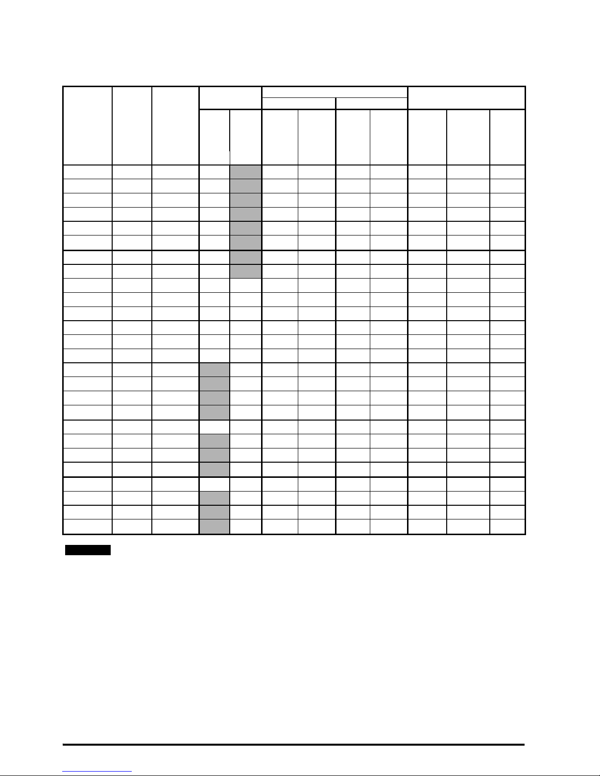
1 Product information
1.1 Ratings
Model
Input
phases
Max.
cont
input
current
Max input
fuse rating
Nominal cable size
Output current
European USA
1 Ph 3 Ph Input Output Input Output
Max.
cont
output
current
Nominal
power
Motor
power
ph A A A
mm
2
mm
2
AWG AWG A kW hp
01100017 1 8.7 10 1 1 16 16 1.7 0.25 0.33
01100024 1 11.1 16
1 1 14 16 2.4 0.37 0.5
01200017 1 4.5 6
1 1 16 16 1.7 0.25 0.33
01200024 1 5.3 6
1 1 16 16 2.4 0.37 0.5
01200033 1 8.3 10
1 1 16 16 3.3 0.55 0.75
01200042 1 10.4 16
1 1 16 16 4.2 0.75 1
02100042 1 18.8 20
2.5 1 12 16 4.2 0.75 1
02100056 1 24 25
4 1 10 16 5.6 1.1 1.5
02200024 1 / 3 5.3/4.1 6 6 1 1 16 16 2.4 0.37 0.5
02200033 1 / 3 8.3/6.7 10 10 1 1 16 16 3.3 0.55 0.75
02200042 1 / 3 10.4/7.5 16 10 1 1 16 16 4.2 0.75 1
02200056 1 / 3 14.9/11.3 20 15 2.5/1.5 1 12/14 16 5.6 1.1 1.5
02200075 1 / 3 18.1/13.5 20 15 2.5 1 12 16 7.5 1.5 2
02400013 3 2.4 6 1 1 16 16 1.3 0.37 0.5
02400018 3 2.9
6 1 1 16 16 1.8 0.55 0.75
02400023 3 3.5
6 1 1 16 16 2.3 0.75 1
02400032 3 5.1
6 1 1 16 16 3.2 1.1 1.5
02400041 3 6.2
10 1 1 16 16 4.1 1.5 2
03200100 1 / 3 23.9/17.7 25 20 4 1.5 10/12 14 10 2.2 3
03400056 3 8.7
10 1 1 14 16 5.6 2.2 3
03400073 3 12.2
16 1.5 1 12 16 7.3 3 3
03400094 3 14.8
16 2.5 1.5 12 14 9.4 4 5
04200133 1 / 3 23.7/16.9 25 20 4/2.5 2.5 10 12 13.3 3 3
04200176 3 21.3
25 4 2.5 10 12 17.6 4 5
04400135 3 16.3
20 2.5 2.5 10 12 13.5 5.5 7.5
04400170 3 20.7
25 4 2.5 10 12 17 7.5 10
The nominal cable sizes shown in the table above, are provided as a guide only. Ensure
that the cables used conform to the local wiring regulations.
NOTE
Page 9
Unidrive M300/HS30 Quick Start Guide 9
Issue Number: 7
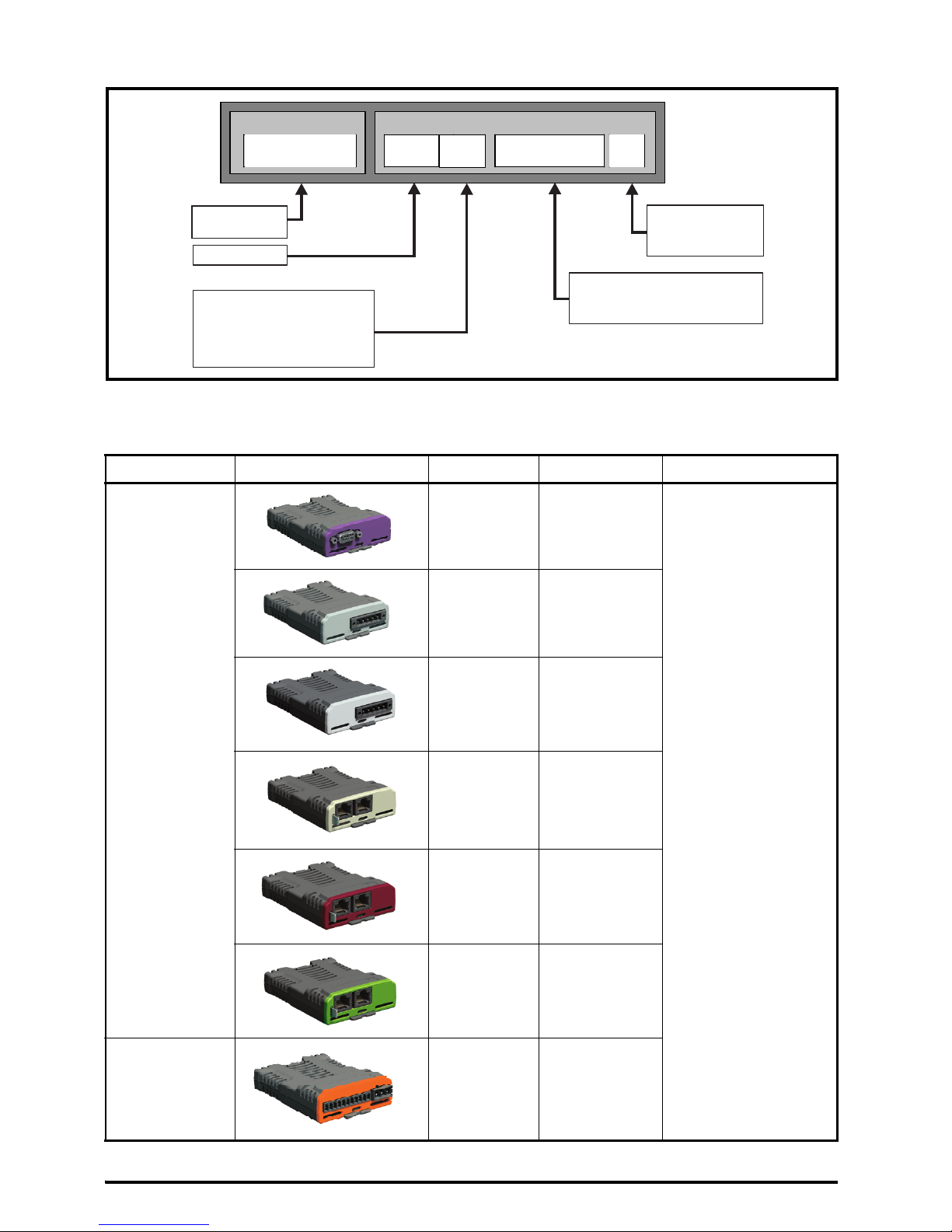
Figure 1-1 Model number structure
2Options
Table 2-1 System Integration (SI) option module identification
Type Option module Color Name Further details
Fieldbus
Purple SI-PROFIBUS
See relevant option
module User Guide
Medium
Grey
SI-DeviceNet
Light Grey SI-CANopen
Beige SI-Ethernet
Brown Red SI-EtherCAT
Yello w
Green
SI-PROFINET V2
Automation
(I/O expansion)
Orange SI-I/O
Product line:
M300 / HS30
Frame size:
Current Rating :
Heavy Duty current rating x10
Drive Format :
A – AC in AC out
Voltage rating
:
1 - 100 V (100 - 120 ± 10 %)
2 - 200 V (200 - 240 ± 10 %)
4 - 400 V (380 - 480 ± 10 %)
Derivative
Electrical Specifications
M300 - 03 4 00073 A
Page 10
10 Unidrive M300/HS30 Quick Start Guide
Issue Number: 7
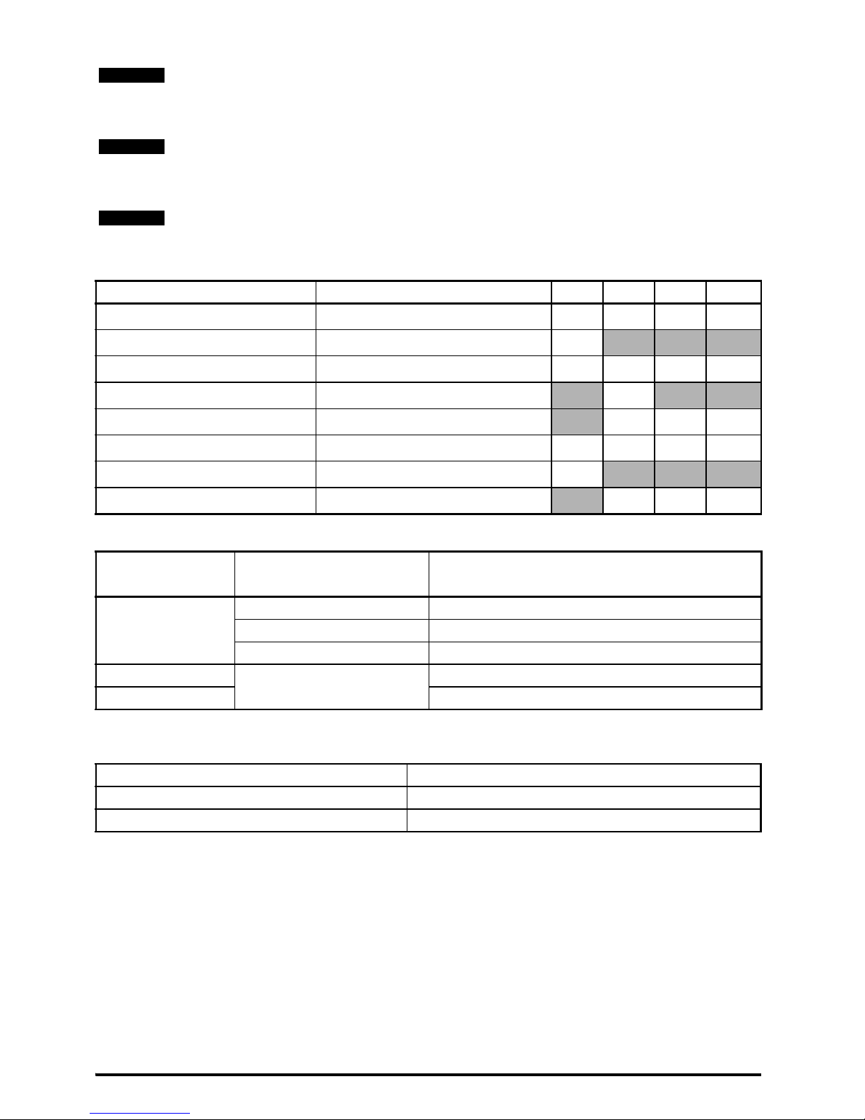
Table 2-2 Adaptor Interface (AI) option module identification
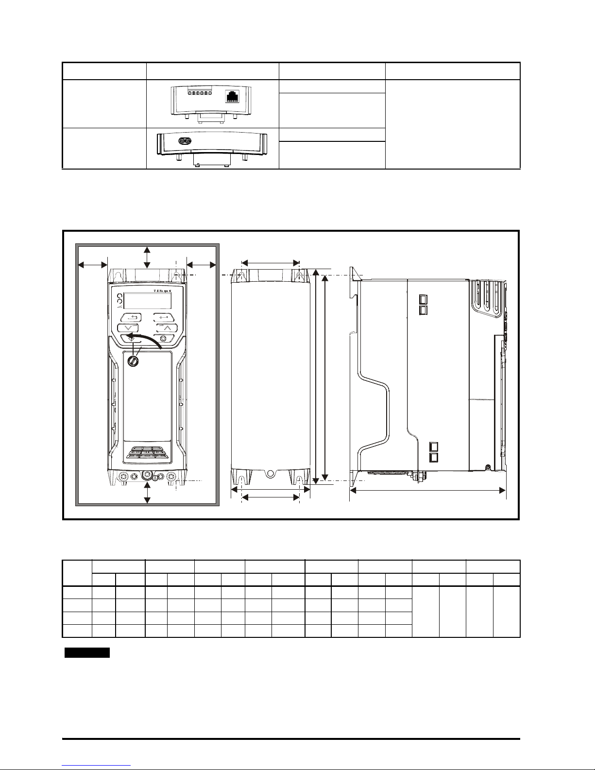
3 Mechanical installation
The drives can be panel mounted with 0 mm space between the drives. For further information on
mechanical installation refer to the Power Installation Guide.
To remove the terminal cover, use a flat bladed screwdriver to rotate the terminal cover locating clip
by approximately 30° in a counter clockwise direction, and then slide the cover down.
Type Option module Name Further Details
Communications
AI-485 Adaptor
See Control User Guide
AI-485 24V Adaptor
Backup
AI-Backup Adaptor
AI-Smart Adaptor
Drive
Size
HWD M1M2∅ AB*
mm in mm in mm in mm in mm in mm in mm in mm in
1 160 6.30 75 2.95 130 5.12 143 5.70 53 2.08 5 0.2
0 0.00 100 3.93
2 205 8.07 75 2.95 150 5.91 194 7.63 55 2.17 5 0.2
3 226 8.90 90 3.54 160 6.30 215 8.46 70.7 2.80 5 0.2
4 277 10.91 115 4.53 175 6.89 265 10.43 86 3.40 6 0.23
A minimum clearance of 100 mm (3.94 in) above and below Frame 01 to 04 products is
required for applications where the product is subjected to rated load and rated ambient
temperature.
A
W
M2
M2
B
D
B
A
HM1
Cover
release
NOTE
Page 11
Unidrive M300/HS30 Quick Start Guide 11
Issue Number: 7
Table 3-1 Tools requi re d
Table 3-2 Recommended torque settings
Table 3-3 Tightening torque for mounting feet
* A minimum clearance of 50 mm (1.97 in) above and below Frame 01 to 04 products is
permissible in applications where either the ambient operating temperature is 35 °C
(95 °F) or less or the average output current is derated by 20 %.
Derating for reduced clearances is to be applied in addition to the derating for increased
switching frequency if operating above 3 kHz. Refer to the Power Installation Guide for the
current derating due to an increase in switching frequency.
If Din rail mounting is used in an installation, then mounting screws should be used to
secure the drive to the back plate.
Tool Location Size 1 Size 2 Size 3 Size 4
Small terminal screwdriver Control, relay and STO terminals
9999
3 mm Flat-bladed screwdriver Power terminals
9
5 mm Flat-bladed screwdriver Terminal cover
9999
4 mm Flat-bladed screwdriver AC power terminals
9
Philips screwdriver Power terminals
999
Torx 10 driver EMC & MOV screws
9999
Torx 15 driver Fan screw
9
Torx 20 driver Fan screw
999
Model size
Terminal block
description
Torque settings
All
Control terminals 0.2 N m (0.15 Ib ft)
Relay terminals 0.5 N m (0.37 Ib ft)
Ground terminals 1.5 N m (1.10 Ib ft)
1
Power terminals
0.5 N m (0.37 Ib ft)
2, 3, 4 1.4 N m (1.03 Ib ft)
Drive size Tightening torque
1 to 3 1.3 N m (1 lb ft) to 1.6 N m (1.2 lb ft)
4 2.5 N m (1.8 lb ft) to 2.8 N m (2.1 lb ft)
NOTE
NOTE
NOTE
Page 12
12 Unidrive M300/HS30 Quick Start Guide
Issue Number: 7
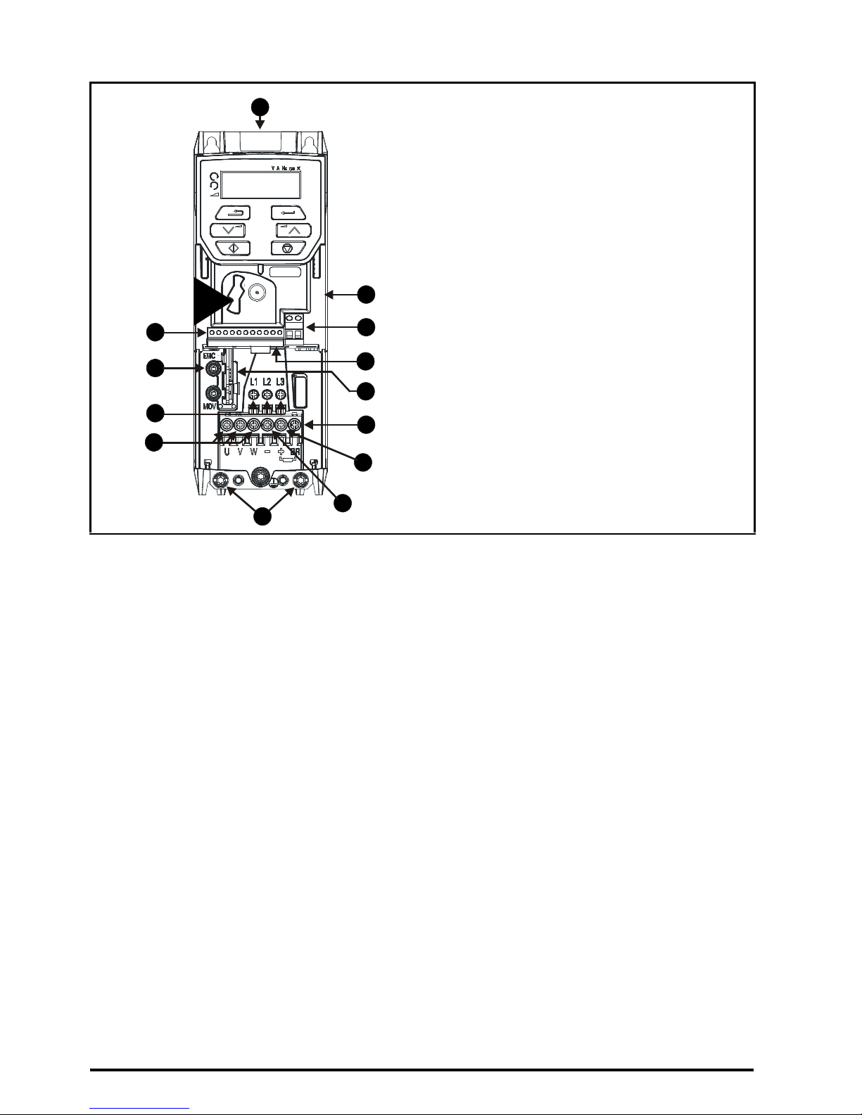
Figure 3-1 Feature diagram (size 2 shown)
* Before removing the screw, refer to section 4.5 EMC on page 22.
6
8
9
5
7
12
4
1
3
2
11
10
2
13
3
Key
1. Rating label (On side of drive)
2. Identification label
3. Option module connection
4. Relay connections
5. Control connections
6. Braking terminal
7. Internal EMC filter screw
*
8. DC bus +
9. DC bus -
10. Motor connections
11. AC supply connections
12. Ground connections
13. Safe Torque Off connections
Page 13
Unidrive M300/HS30 Quick Start Guide 13
Issue Number: 7
4 Electrical installation
An overlay of the electrical connections / terminals is included on the back page of this manual.
4.1 AC supply requirements
Voltage:
100 V drive: 100 V to 120 V ±10 %
200 V drive: 200 V to 240 V ±10 %
400 V drive: 380 V to 480 V ±10 %
Number of phases: 3
Maximum supply imbalance: 2 % negative phase sequence (equivalent to 3 % voltage imbalance
between phases).
Frequency range: 45 to 66 Hz
For UL compliance only, the maximum supply symmetrical fault current must be limited to 100 kA.
4.2 External braking resistor
4.2.1 Minimum resistance values and peak power rating for the braking resistor
at 40 °C (104 °F)
Table 4-1 Braking resistor resistance and power rating (100 V)
* Resistor tolerance: ±10 %
On the size 2 110 V drives or when connecting single phase to a dual rated 200 V unit, the
supply should be connected to L1 and L3. Also the DC bus (-) terminal on 110 V drives
has no internal connection. The 110 V drives use a voltage doubler circuit on the input,
therefore the default for Motor Rated Voltage (Pr 08) is 230 V.
Overload protection
When an external braking resistor is used, it is essential that an overload protection device
is incorporated in the braking resistor circuit; as shown in the electrical diagram on the
back cover.
Model
Minimum
resistance*
Ω
Instantaneous
power rating
kW
Continuous
power rating
kW
01100017
130 1.1
0.25
01100024 0.37
02100042
68 2.2
0.75
02100056 1.1
NOTE
WARNING
Page 14

14 Unidrive M300/HS30 Quick Start Guide
Issue Number: 7
Table 4-2 Braking resistor resistance and power rating (200 V)
Table 4-3 Braking resistor resistance and power rating (400 V)
* Resistor tolerance: ±10 %
Model
Minimum
resistance*
Ω
Instantaneous
power rating
kW
Continuous
power rating
kW
01200017
130 1.1
0.25
01200024 0.37
01200033 0.55
01200042 0.75
02200024
68 2.2
0.37
02200033 0.55
02200042 0.75
02200056 1.1
02200075 1.5
03200100 45 3.3 2.2
04200133
22 6.0
3.0
04200176 4.0
Model
Minimum
resistance*
Ω
Instantaneous
power rating
kW
Continuous
power rating
kW
02400013
270 2.2
0.37
02400018 0.55
02400023 0.75
02400032 1.1
02400041 1.5
03400056
100 6.0
2.2
03400073 3
03400094 4
04400135
50 11.2
5.5
04400170 7.5
Page 15
Unidrive M300/HS30 Quick Start Guide 15
Issue Number: 7
4.3 Ground leakage
The ground leakage current depends upon whether the internal EMC filter is installed or not. The
drive is supplied with the filter installed. Instructions for removing the internal filter are given in
section 4.5.2 Removing the internal EMC filter on page 22.
With internal filter installed:
Size 1:
8.1 mA* AC at 110 V, 50 Hz
9.5 mA* AC at 230 V, 50 Hz
Size 2:
13 mA* AC at 110 V, 50 Hz (1 phase)
6.3 mA* AC at 230 V, 50 Hz (3 phase)
17.5 mA* AC at 230 V, 50 Hz (1 phase)
9.2 mA* AC at 415 V, 50 Hz (3 phase)
Size 3:
17.1 mA* AC at 230 V 50 Hz (1 phase)
5.9 mA* AC at 230 V 50 Hz (3 phase)
5.7 mA* AC at 415 V 50 Hz (3 phase)
Size 4:
21.3 mA* AC at 230 V 50 Hz (1 phase)
9.7 mA* AC at 230 V 50 Hz (3 phase)
13.3 mA* AC at 415 V 50 Hz (3 phase)
*Proportional to the supply voltage and frequency.
With internal filter removed:
Size 1: <1 mA
Size 2: 110 V: < 1.2 mA
230 V: < 1 mA
415 V: < 2.3 mA
Size 3: 230 V: < 1.6 mA
415 V: < 1 mA
Size 4: < 1 mA
The above leakage currents are just the leakage currents of the drive and do not take into
account any leakage currents of the motor or motor cable.
When the internal filter is installed the leakage current is high. In this case a permanent
fixed ground connection must be provided, or other suitable measures taken to prevent a
safety hazard occurring if the connection is lost.
When the leakage current exceeds 3.5 mA, a permanent fixed ground connection must be
provided using two independent conductors each with a cross-section equal to or
exceeding that of the supply conductors. The drive is provided with two ground
connections to facilitate this. Both ground connections are necessary to meet EN 618005-1: 2007.
NOTE
WARNING
WARNING
Page 16
16 Unidrive M300/HS30 Quick Start Guide
Issue Number: 7
4.3.1 Use of residual current device (RCD)
There are three common types of ELCB / RCD:
1. AC - detects AC fault currents
2. A - detects AC and pulsating DC fault currents (provided the DC current reaches zero at least
once every half cycle)
3. B - detects AC, pulsating DC and smooth DC fault currents
• Type AC should never be used with drives.
• Type A can only be used with single phase drives
• Type B must be used with three phase drives
If an external EMC filter is used with an ELCB / RCD, a delay of at least 50 ms should be
incorporated to ensure spurious trips are not seen. The leakage current is likely to exceed the trip
level if all of the phases are not energized simultaneously.
4.4 Control terminal configurations and wiring
The setting of Pr 05 automatically sets the drive configuration.
Action will only occur if the drive is inactive and no User Actions are running. Otherwise, the
parameter will return to its pre altered value on exit from edit mode. All parameters are saved if this
parameter changes.
Only type B ELCB / RCD are suitable for use with 3 phase inverter drives.
05 Drive Configuration
RW Txt PT US
OL
Ú
AV (0), AI (1), AV.Pr (2), AI.Pr (3),
PrESEt (4), PAd (5), PAd.rEF (6),
E.Pot (7), torquE (8), Pid (9)
Ö
AV (0)
RFC-A
Value Text Description
0AV
Analog input 1 (voltage) or Analog input 2 (voltage) selected by terminal
(Local/Remote)
1AI
Analog input 1 (current) or Analog input 2 (voltage) selected by terminal
(Local/Remote)
2AV.Pr
Analog input 1 (voltage) or 3 presets selected by terminal
3 AI.Pr
Analog input 1 (current) or 3 presets selected by terminal
4PrESEt
Four presets selected by terminal
5PAd
Keypad reference
6 PAd.rEF
Keypad reference with terminal control
7E.Pot
Electronic Potentiometer
8 torquE
Torque mode, Analog input 1 (current frequency reference) or Analog input 2
(voltage torque reference) selected by terminal
9Pid
PID mode, Analog input 1 (current feedback source) and Analog input 2
(voltage reference source)
WARNING
Page 17

Unidrive M300/HS30 Quick Start Guide 17
Issue Number: 7
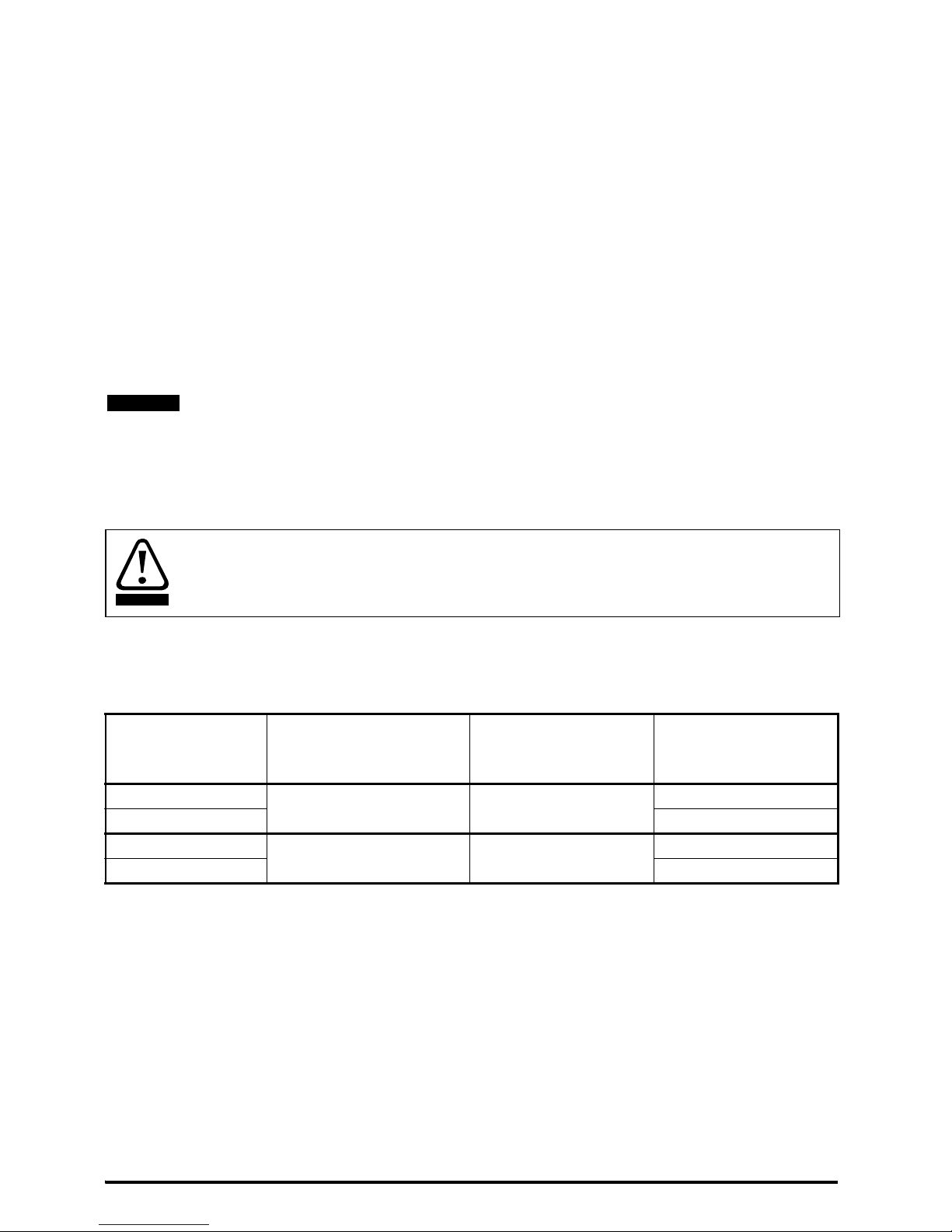
Figure 4-1 Pr 05 = AV
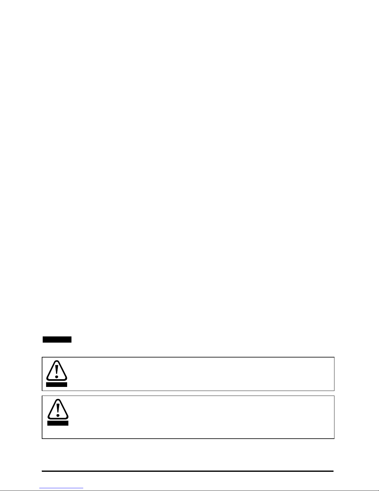
Figure 4-2 Pr 05 = AI
1
2
4
0V
Voltage speed reference
input (AI 1)
Voltage speed
reference input (AI 2)
5
7
Analog output 1
(motor frequency)
+ 10 V output
9
10
11
Digital output
(zero frequency)
Unassigned
12
1314Run reverse
Run forward
Analog input 1/
input 2 select
+ 24 V output
10k
10k
1
2
4
0V
Current speed reference
input (AI 1)
Voltage speed
reference input (AI 2)
5
7
Analog output 1
(motor frequency)
+ 10 V output
9
10
11
Digital output
(zero frequency)
Unassigned
12
1314Run reverse
Run forward
Analog input 1/
input 2 select
+ 24 V output
10k
Current speed
reference input
Page 18
18 Unidrive M300/HS30 Quick Start Guide
Issue Number: 7
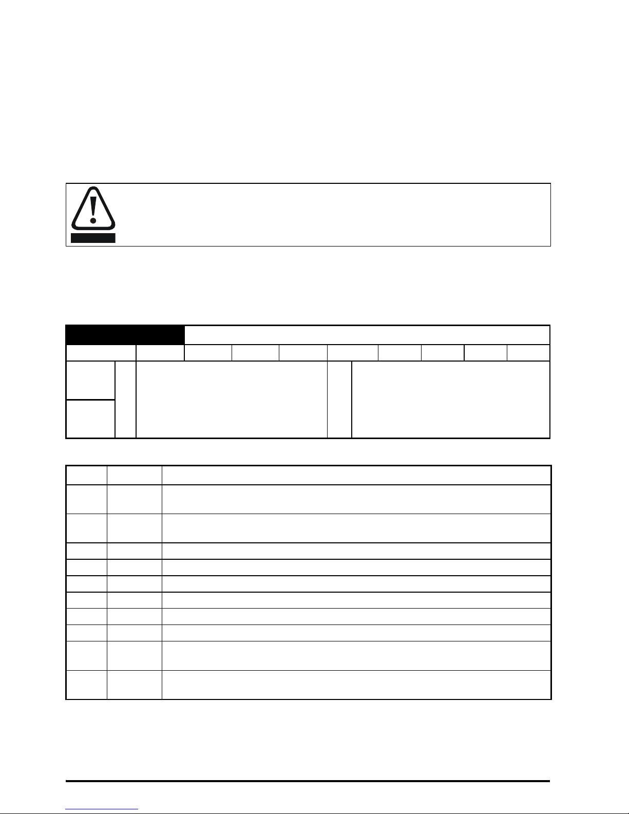
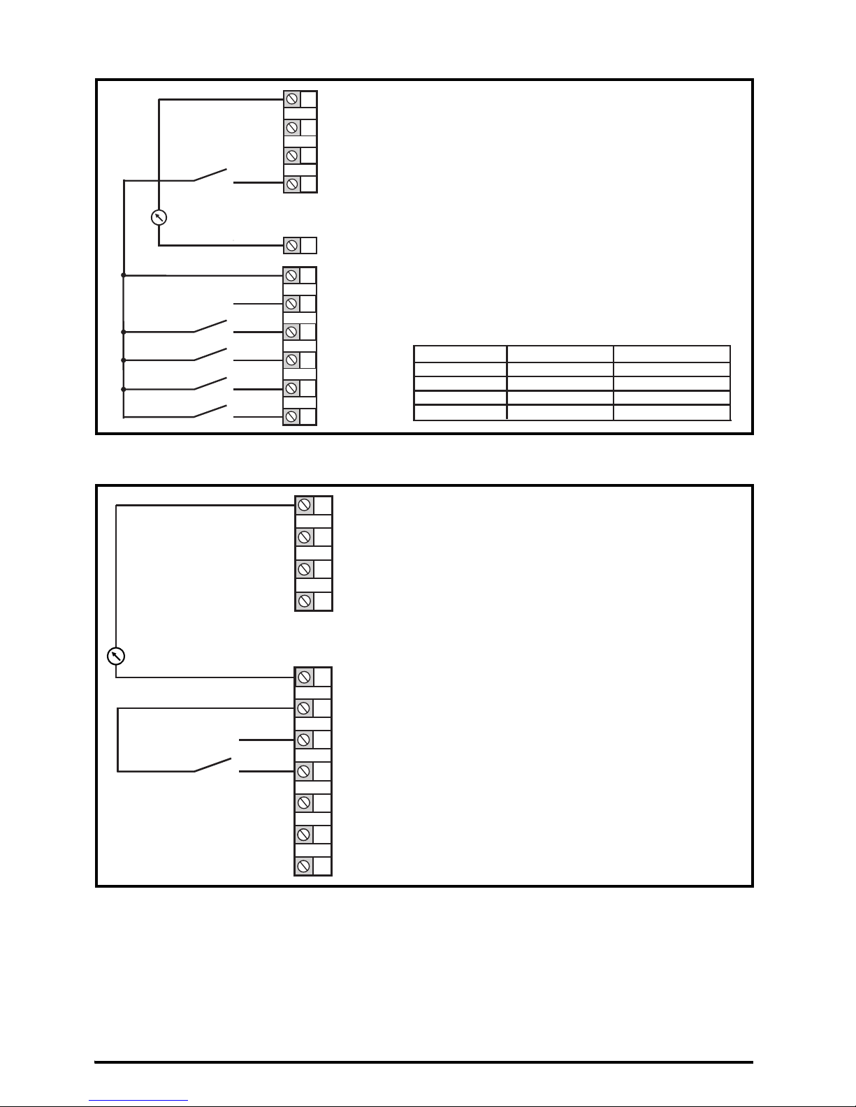
Figure 4-3 Pr 05 = AV.Pr
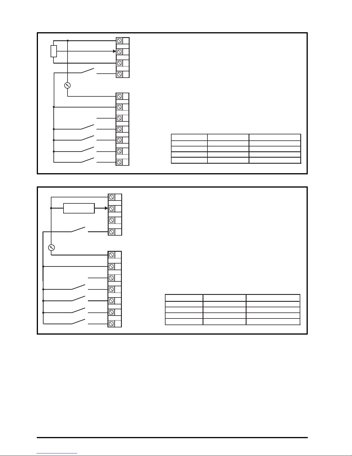
Figure 4-4 Pr 05 = AI.Pr
* Refer to the Control User Guide.
1
2
4
0V
Voltage speed reference
input (AI 1)
Reference select
5
7
Analog output 1
(motor frequency)
+ 10 V output
9
10
11
Digital output
(zero frequency)
Unassigned
12
1314Run reverse
Run forward
+ 24 V output
10k
Reference select
Terminal5 Terminal14
Reference selected
0
0
1
1
0
1
0
1
Analog reference 1*
Preset speed 2 *
Preset speed 3 *
Preset speed 4 *
1
2
4
0V
Current speed reference
input (AI 1)
Reference select
5
7
Analog output 1
(motor frequency)
+ 10 V output
9
10
11
Digital output
(zero frequency)
Unassigned
12
13
14
Run reverse
Run forward
+ 24 V output
Current speed
reference input
Reference select
Terminal5 Terminal14
Reference selected
0
0
1
1
0
1
0
1
Analog reference 1*
Preset speed 2*
Preset speed 3*
Preset speed 4*
Page 19
Unidrive M300/HS30 Quick Start Guide 19
Issue Number: 7
Figure 4-5 Pr 05 = PrESEt
* Refer to the Control User Guide.
Figure 4-6 Pr 05 = PAd
1
2
4
0V
Voltage speed reference
input (AI 1)
Reference select
5
7
Analog output 1
(motor frequency)
+ 10 V output
Digital output
(zero frequency)
9
10
11
Unassigned
12
13
14
Reference select
Run forward
+ 24 V output
Run reverse
Terminal5 Terminal14
Reference selected
0
0
1
1
0
1
0
1
Preset speed 1*
Preset speed 2*
Preset speed 3*
Preset speed 4*
120V
Voltage speed reference
input (AI 1)
7
Analog output 1
(motor frequency)
9
10
11
Digital output
(zero frequency)
Unassigned
12
13
14
Analog input 1/
input 2 select
Run forward
+ 24 V output
Run reverse
4
5
+ 10 V output
Voltage speed reference
input (AI 2)
When Pr 05 is set to PAd, to run in
reverse:
•Set Pr 17 to On
The Keypad reference can now be
set to a negative frequency to run the
motor in the reverse direction.
Page 20
20 Unidrive M300/HS30 Quick Start Guide
Issue Number: 7
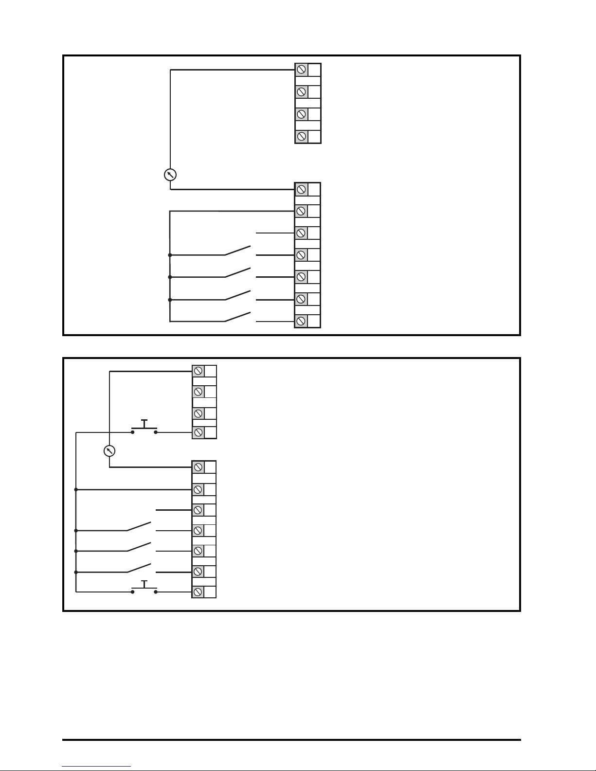
Figure 4-7 Pr 05 = PAd.rEF
Figure 4-8 Pr 05 = E.Pot
* Refer to the Control User Guide.
120V
Voltage speed reference
input (AI 1)
7
Analog output 1
(motor frequency)
9
10
11
Digital output
(zero frequency)
Unassigned
12
13
14
Analog input 1/
input 2 select
Run forward
+ 24 V output
Run reverse
4
5
+ 10 V output
Voltage speed reference
input (AI 2)
1
2
4
0V
Voltage speed reference
input (AI 1)
5
7
Analog output 1
(motor frequency)
+ 10 V output
9
10
11
Digital output
(zero frequency)
Unassigned
12
13
14
UP
Run forward
+ 24 V output
Run reverse
DOWN
When Pr 05 is set to E.Pot, the following
parameters may need to be adjusted:
• Motorized pot up/down rate (s/100 %)*
• Motorized pot bipolar select (0 =
unipolar, 1 = bipolar)*
• Motorized pot mode: 0 = zero at powerup,
1 = last value at power-up,
2 = zero at power-up and only change
when drive is running,
3 = last value at power-up and only
change when drive is running,
4 = zero at power-up and drive disabled,
only change when drive is running.
Page 21

Unidrive M300/HS30 Quick Start Guide 21
Issue Number: 7
Figure 4-9 Pr 05 = torquE
Figure 4-10 Pr 05 = Pid
120V
Current speed reference
input (AI 1)
Current speed
reference input
4
Torque reference
input (AI 2)
5
7
Analog output 1
(motor frequency)
+ 10 V output
9
10
11
Digital output
(zero frequency)
Unassigned
12
1314Run reverse
Run forward
Torque mode select
+ 24 V output
10k
When torque mode is selected and the drive is connected to an unloaded motor, the
motor speed may increase rapidly to the maximum speed (Pr 02 +10 %)
WARNING
1
2
4
0V
Pidfeedback
input (AI 1)
5
7
Analog output 1
(motor frequency)
+ 10 V output
9
10
11
Digital output
(zero frequency)
Unassigned
12
1314Run reverse
Run forward
Pid enable
+ 24 V output
4-20 mA Pid
feedback input
0-10 V Pid
reference input
Pid reference
input (AI 2)
When Pr 05 is set to Pid, the following
parameters may need to be adjusted:
• PID proportional gain
• PID integral gain
• PID feedback invert
• PID output upper limit (%)
• PID output lower limit (%)
Page 22

22 Unidrive M300/HS30 Quick Start Guide
Issue Number: 7
4.5 EMC
4.5.1 Internal EMC filter
It is recommended that the internal EMC filter be kept in place unless there is a specific reason for
removing it. If the drive is used as a motoring drive as part of a regen system, then the internal EMC
filter must be removed.
The internal EMC filter reduces radio-frequency emission into the line power supply.
For longer motor cables, the filter continues to provide a useful reduction in emission levels and
when used with any length of shielded motor cable up to the limit for the drive, it is unlikely that
nearby industrial equipment will be disturbed. It is recommended that the filter be used in all
applications unless the instructions given above require it to be removed, or where the ground
leakage current is unacceptable.
4.5.2 Removing the internal EMC filter
Figure 4-11 Removal of the internal EMC filter (size 2 shown)
To electrically disconnect the internal EMC filter, remove the screw as shown above (1).
4.5.3 Further EMC precautions
Further EMC precautions are required if more stringent EMC emission requirements apply:
• Operation in the first environment of EN 61800-3: 2004+A1:2012
• Conformity to the generic emission standards
• Equipment which is sensitive to electrical interference operating nearby
In this case it is necessary to use:
• The optional external EMC filter
• A shielded motor cable, with shield clamped to the grounded metal panel
The supply must be disconnected before removing the internal EMC filter.
WARNING
1
Page 23

Unidrive M300/HS30 Quick Start Guide 23
Issue Number: 7
• A shielded control cable, with shield clamped to the grounded metal panel
Full instructions are given in the Power Installation Guide.
A full range of external EMC filters are also available for use with Unidrive M300/HS30, shown in the
Power Installation Guide.
4.6 Safe Torque Off (STO)
The Safe Torque Off function provides a means for preventing the drive from generating torque in the
motor with a very high level of integrity. It is suitable for incorporation into a safety system for a
machine. It is also suitable for use as a conventional drive enable input.
The safety function is active when either one or both STO inputs are in the logic-low state as
specified in the control terminal specification. The function is defined according to EN 61800-5-2 and
IEC 61800-5-2 as follows. (In these standards a drive offering safety-related functions is referred to
as a PDS(SR)):
'Power, that can cause rotation (or motion in the case of a linear motor), is not applied to the motor.
The PDS(SR) will not provide energy to the motor which can generate torque (or force in the case of
a linear motor)'.
This safety function corresponds to an uncontrolled stop in accordance with stop category 0 of IEC
60204-1. The Safe Torque Off function makes use of the special property of an inverter drive with an
induction motor, which is that torque cannot be generated without the continuous correct active
behavior of the inverter circuit. All credible faults in the inverter power circuit cause a loss of torque
generation.
The Safe Torque Off function is fail-safe, so when the Safe Torque Off input is disconnected the drive
will not operate the motor, even if a combination of components within the drive has failed. Most
component failures are revealed by the drive failing to operate. Safe Torque Off is also independent
of the drive firmware.
For more information regarding the Safe Torque Off input, please see the Control User Guide.
The design of safety-related control systems must only be done by personnel with the
required training and experience. The Safe Torque Off function will only ensure the safety
of a machine if it is correctly incorporated into a complete safety system. The system must
be subject to a risk assessment to confirm that the residual risk of an unsafe event is at
an acceptable level for the application
Safe Torque Off does not provide electrical isolation. The supply to the drive must be
disconnected by an approved isolation device before gaining access to power
connections.
It is essential to observe the maximum permitted voltage of 5 V for a safe low (disabled)
state of Safe Torque Off. The connections to the drive must be arranged so that voltage
drops in the 0 V wiring cannot exceed this value under any loading condition. It is strongly
recommended that the Safe Torque Off circuits be provided with a dedicated 0 V
conductors which should be connected to terminals 32 and 33 at the drive.
WARNING
WARNING
WARNING
Page 24

24 Unidrive M300/HS30 Quick Start Guide
Issue Number: 7
5 Keypad and display
The keypad and display provide information to the user regarding the operating status of the drive,
alarms and trip codes, and provide the means for changing parameters, stopping and starting the
drive, and the ability to perform a drive reset.
Figure 5-1 Unidrive M300/HS30 keypad detail
(1) The Enter button is used to enter parameter view or edit mode, or to accept a parameter edit.
(2, 5) The Navigation keys can be used to select individual parameters or to edit parameter values. In
keypad mode, the ‘Up’ and ‘Down’ keys are also used to increase or decrease the motor speed.
(3) The Stop / Reset button (red) is used to stop and reset the drive in keypad mode. It can also be
used to reset the drive in terminal mode.
(4) The Start button (green) is used to start the drive in keypad mode.
(6) The Escape button is used to exit from the parameter edit / view mode or disregard a parameter
edit.
Table 5-1 Status indications
String Description Drive output stage
inh
The drive is inhibited and cannot be run. The Safe Torque
Off signals are not applied to Safe Torque Off terminals or
is set to 0.
Disabled
rdy
The drive is ready to run. The drive enable is active, but the
drive inverter is not active because the final drive run is not
active.
Disabled
StoP The drive is stopped / holding zero speed. Enabled
S.Loss Supply loss condition has been detected. Enabled
dc.inj The drive is applying DC injection braking. Enabled
Er
The drive has tripped and no longer controlling the motor.
The trip code appears in the display.
Disabled
UV
The drive is in the under voltage state either in low voltage
or high voltage mode.
Disabled
HEAt The motor pre-heat function is active. Enabled
7
1
2
3
6
5
4
Page 25

Unidrive M300/HS30 Quick Start Guide 25
Issue Number: 7
5.1 Saving parameters
When changing a parameter in Menu 0, the new value is saved when pressing the Enter button
to return to parameter view mode from parameter edit mode.
If parameters have been changed in the advanced menus, then the change will not be saved
automatically. A save function must be carried out.
Procedure
1. Select ‘Save' in Pr 00 or Pr mm.000 (alternatively enter a value of 1001 in Pr 00 or Pr mm.000)
2. Either:
• Press the red reset button
• Carry out a drive reset through serial communications by setting Pr 10.038 to 100
5.2 Restoring parameter defaults
Restoring parameter defaults by this method saves the default values in the drives memory. User
Security Status (Pr 10) and User Security Code (Pr 25) are not affected by this procedure.
Procedure
1. Ensure the drive is not enabled, i.e. drive is in inhibit or under voltage state.
2. Select 'Def.50’ or 'Def.60' in Pr 00 or Pr mm.000 (alternatively, enter 1233 (50 Hz settings) or
1244 (60 Hz settings) in Pr 00 or Pr mm.000).
3. Either:
• Press the red reset button
• Carry out a drive reset through serial communications by setting Pr 10.038 to 100
Page 26

26 Unidrive M300/HS30 Quick Start Guide
Issue Number: 7
6 Basic parameters (Menu 0)
Menu 0 is used to bring together various commonly used parameters for basic easy set up of the
drive.
6.1 Menu 0: Basic parameters
RFC-A is not available on Unidrive HS30 drives.
Parameter
Range
(Ú) Default (Ö)
Type
OL RFC-A OL RFC-A
01 Minimum Speed 0.00 to Pr 02 Hz 0.00 Hz RW Num US
02 Maximum Speed 0.00 to 550.00 Hz
Def.50: 50.00 Hz
Def.60: 60.00 Hz
RW Num US
03 Acceleration Rate 1 0.0 to 32000.0 s/100 Hz 5.0 s/100 Hz RW Num US
04 Deceleration Rate 1 0.0 to 32000.0 s/100 Hz 10.0 s/100 Hz RW Num US
05 Drive Configuration
AV (0), AI (1), AV.Pr (2), AI.Pr (3),
PrESEt (4), PAd (5), PAd.rEF (6),
E.Pot (7), torquE (8), Pid (9)
AV ( 0 ) R W Txt PT US
06 Motor Rated Current 0.00 to Drive Rating A
Maximum Heavy Duty
Rating A
RW Num RA US
07 Motor Rated Speed* 0.0 to 33000.0 rpm
Def.50:
1500.0 rpm
Def.60:
1800.0 rpm
Def.50:
1450.0 rpm
Def.60:
1750.0 rpm
RW Num US
08 Motor Rated Voltage 0 to 240 V or 0 to 480 V
110V drive: 230 V
200V drive: 230 V
400V drive Def.50: 400 V
400V drive Def.60: 460 V
RW Num RA US
09
Motor Rated Power
Factor**
0.00 to 1.00 0.85 RW Num RA US
10 User Security Status
LEVEL.1 (0), LEVEL.2 (1), ALL (2),
StAtUS (3), no.Acc (4)
LEVEL.1 (0) RW Num ND PT
11
Start/Stop Logic
Select
0 to 6 0 RW Num US
15 Jog Reference 0.00 to 300.00 Hz 1.50 Hz RW Num US
16 Analog Input 1 Mode
4-20.S (-6), 20-4.S (-5),
4-20.L (-4), 20-4.L (-3),
4-20.H (-2), 20-4.H (-1), 0-20 (0),
20-0 (1), 4-20.tr (2), 20-4.tr (3),
4-20 (4), 20-4 (5), Volt (6)
Volt (6) RW Txt US
17
Bipolar Reference
Enable
Off (0) or On (1) Off (0) RW Bit US
18 Preset Reference 1 0.00 to Pr 02 Hz 0.00 Hz RW Num US
19 Preset Reference 2 0.00 to Pr 02 Hz 0.00 Hz RW Num US
20 Preset Reference 3 0.00 to Pr 02 Hz 0.00 Hz RW Num US
21 Preset Reference 4 0.00 to Pr 02 Hz 0.00 Hz RW Num US
22
Status Mode
Parameter 2
0.000 to 30.999 4.020 RW Num PT US
23
Status Mode
Parameter 1
0.000 to 30.999 2.001 RW Num PT US
24
Customer Defined
Scaling
0.000 to 10.000 1.000 RW Num US
25 User Security Code 0 to 9999 0 RW Num ND PT US
NOTE
Page 27

Unidrive M300/HS30 Quick Start Guide 27
Issue Number: 7
27
Power-up Keypad
Control Mode
Reference
rESEt (0), LASt (1), PrESEt (2) rESEt (0) RW Txt US
28 Ramp Mode Select
Fast (0), Std (1), Std.bst (2),
Fst.bst (3)
Std ( 1) RW Txt US
29 Ramp Enable Off (0) or On (1) On (1) RW Bit US
30 Parameter Cloning
NonE (0), rEAd (1), Prog (2),
Auto (3), boot (4)
NonE (0) RW Txt NC US
31 Stop Mode
CoASt (0), rP (1),
rP.dc I (2),
dc I (3), td.dc I (4),
diS (5),
CoASt (0), rP (1),
rP.dc I (2),
dc I (3),
td.dc I (4), diS (5),
No.rP (6)
rP (1) RW Txt US
32
Dynamic V to F
Select / Flux
Optimization Select
0 to 1 0 RW Num US
33
Catch A Spinning
Motor
dis (0), Enable (1), Fr.Only (2),
Rv.Only (3)
dis (0) RW Txt US
34 Digital Input 5 Select
Input (0), th.Sct (1), th (2),
th.Notr (3), Fr (4)
Input (0) RW Txt US
35
Digital Output 1
Control
0 to 21 0 RW Num US
36
Analog Output 1
Control
0 to 14 0 RW Txt US
37
Maximum Switching
Frequency
0.667 (0), 1 (1), 2
(2), 3 (3), 4 (4), 6
(5), 8 (6), 12 (7),
16 (8) kHz
2 (2), 3 (3),
4 (4), 6 (5),
8 (6), 12 (7),
16 (8) kHz
3 (3) kHz RW Txt US
38 Autotune 0 to 2 0 to 3 0 RW Num NC US
39
Motor Rated
Frequency***
0.00 to 550.00 Hz
Def.50: 50.00 Hz
Def.60: 60.00 Hz
RW Num RA US
40
Number of Motor
Poles****
Auto (0) to 32 (16) Auto (0) RW Num US
41 Control Mode
Ur.S (0), Ur (1), Fd
(2), Ur.Auto (3), Ur.I
(4), SrE (5),
Fd.tap (6)
Ur.I (4) RW Txt US
42
Low Frequency
Voltage Boost
0.0 to 25.0 % 3.0 % RW Num US
43 Serial Baud Rate
600 (1), 1200 (2),
2400 (3), 4800 (4), 9600 (5),
19200 (6), 38400 (7), 57600 (8),
76800 (9), 115200 (10)
19200 (6) RW Txt US
44 Serial Address 1 to 247 1 RW Num US
45
Reset Serial
Communications
Off (0) or On (1) Off (0) RW Bit ND NC US
46
Brake Controller
Upper Current
Threshold
0 to 200 % 50 % RW Num US
47
Brake Controller
Lower Current
Threshold
0 to 200 % 10 % RW Num US
48
Brake Controller
Brake Release
Frequency
0.00 to 20.00 Hz 1.00 Hz RW Num US
49
Brake Controller
Brake Apply
Frequency
0.00 to 20.00 Hz 2.00 Hz RW Num US
50
Brake Controller
Brake Delay
0.0 to 25.0 s 1.0 s RW Num US
Parameter
Range
(Ú) Default (Ö)
Type
OL RFC-A OL RFC-A
Page 28

28 Unidrive M300/HS30 Quick Start Guide
Issue Number: 7
51
Brake Controller
Post-brake Release
Delay
0.0 to 25.0 s 1.0 s RW Num US
53
Brake Controller
Initial Direction
rEF (0), For (1), rEv (2) rEF (0) RW Txt US
54
Brake Controller
Brake Apply Through
Zero Threshold
0.00 to 25.00 Hz 1.00 Hz RW Num US
55
Brake Controller
Enable
diS (0), rELAy (1), dig IO (2),
USEr (3)
diS (0) RW Txt US
56 Trip 0 0 to 255 RO Txt ND NC PT PS
57 Trip 1 0 to 255 RO Txt ND NC PT PS
58 Trip 2 0 to 255 RO Txt ND NC PT PS
59 OUP Enable Stop (0) or Run (1) Run (1) RW Txt US
60 OUP Status -2147483648 to 2147483647 RO Num ND NC PT
65
Frequency Controller
Proportional Gain
Kp1
0.000 to
200.000 s/rad
0.100 s/rad RW Num US
66
Frequency Controller
Integral Gain Ki1
0.00 to
655.35 s2/rad
0.10 s2/rad
RW Num US
67
Sensorless Mode
Filter
4 (0), 5 (1), 6 (2),
8 (3), 12 (4),
20 (5) ms
4 (0) ms RW Txt US
69 Spin Start Boost 0.0 to 10.0 1.0 RW Num US
70 PID1 Output ±100.00 % RO Num ND NC PT
71
PID1 Proportional
Gain
0.000 to 4.000 1.000 RW Num US
72 PID1 Integral Gain 0.000 to 4.000 0.500 RW Num US
73
PID1 Feedback
Invert
Off (0) or On (1) Off (0) RW Bit US
74
PID1 Output Upper
Limit
0.00 to 100.00 % 100.00 % RW Num US
75
PID1 Output Lower
Limit
±100.00 % -100.00 % RW Num US
76
Action on Trip
Detection
0 to 31 0 RW Num ND NC PT US
77
Maximum Heavy
Duty Current Rating
0.00 to Drive HD Current Rating A RO Num ND NC PT
78 Software Version 0 to 99.99.99 RO Num ND NC PT
79 User Drive Mode OPEn.LP (1), RFC-A (2) OPEn.LP (1) RFC-A (2) RW Txt ND NC PT US
81 Reference Selected -Pr 02 to Pr 02 or Pr 01 to Pr 02 Hz RO Num ND NC PT
82 Pre-ramp Reference -Pr 02 to Pr 02 or Pr 01 to Pr 02 Hz RO Num ND NC PT
83
Final Demand
Reference
-Pr 02 to Pr 02 or Pr 01 to Pr 02 Hz RO Num ND NC PT FI
84 D.C. Bus Voltage 0 to 415 V or 0 to 830 V RO Num ND NC PT FI
85 Output Frequency ± 550.00 Hz RO Num ND NC PT FI
86 Output Voltage 0 to 325 V or 0 to 650 V RO Num ND NC PT FI
87 Motor Rpm*****
± 33000.0 rpm
RO Num ND NC PT FI
88 Current Magnitude 0 to Drive Maximum Current A RO Num ND NC PT FI
89
Torque Producing
Current
± Drive Maximum Current A
RO Num ND NC PT FI
90
Digital I/O Read
Word
0 to 2047 RO Bin ND NC PT
91 Reference On Off (0) or On (1) RO Bit ND NC PT
92 Reverse Select Off (0) or On (1) RO Bit ND NC PT
Parameter
Range
(Ú) Default (Ö)
Type
OL RFC-A OL RFC-A
Page 29

Unidrive M300/HS30 Quick Start Guide 29
Issue Number: 7
* Setting Pr 07 to 0.0 will disable slip compensation. With the Unidrive HS30, the maximum is 80,000.0 rpm.
** Following a rotating autotune, Pr 09 is continuously written to by the drive, calculated from the value of Stator
Inductance (Pr 05.025). To manually enter a value into Pr 09, Pr 05.025 will need to be set to 0. Refer to the
description of Pr 05.010 in the Parameter Reference Guide for further details.
*** With the Unidrive HS30, the maximum is 3000.00 Hz.
**** If this parameter is read via serial communications, it will show pole pairs.
***** With the Unidrive HS30, the maximum is 180,000.0 rpm.
93 Jog Select Off (0) or On (1) RO Bit ND NC PT
94 Analog Input 1 ± 100.00 % RO Num ND NC PT FI
95 Analog Input 2 ± 100.00 % RO Num ND NC PT FI
RW
Read /
Write
RO
Read
only
Num
Number
parameter
Bit
Bit
parameter
Txt Text string Bin
Binary
parameter
FI Filtered
ND
No
default
value
NC
Not
copied
PT
Protected
parameter
RA
Rating
dependent
US User save PS
Power-down
save
DE Destination
Parameter
Range
(Ú) Default (Ö)
Type
OL RFC-A OL RFC-A
Page 30

30 Unidrive M300/HS30 Quick Start Guide
Issue Number: 7
Figure 6-1 Menu 0 logic diagram
2
5
Analog reference
Keypad reference
00.XXX
00.XXX
Key
Read-write
(RW)
parameter
Read-only
(RO)
parameter
Input
terminals
Output
terminals
X
X
X
X
The parameters are all shown in their default settings
18
Preset
Reference 1
Preset frequency
reference
14
0
5
17
Bipolar
Analog Input 1
Analog Input
1 Mode
Analog Input 1/
Input 2 select
Analog Input 2
Reference
Enable
AV
PrESEt
PAd
PAd.rEF
E. Pot
torquE
Pid
6
7
8
9
01.015
16
Pr
set
01.050
>1
05
Drive
Configuration
AI
AV.Pr
AI.Pr
1
2
3
4
19
20
21
Preset Reference 2
Preset Reference 3
Preset Reference 4
94
Analog Input 1
95
81
Reference
Selected
15
Jog Reference
93
Jog
Select
XX
XX
Read-write
(RW)
parameter
Read-only
(RO)
parameter
Menu 0 only
Analog Input 2
Page 31

Unidrive M300/HS30 Quick Start Guide 31
Issue Number: 7
Frequency
Controller
Integral
Gain Ki 1
Frequency
Controller
Proportional
Gain Kp 1
65
66
RFC-A Speed-loop
PID
gains
7
10
AT ZERO FREQUENCY
Power stage
Control mode
Dynamic
V/f
Select
Low Frequency
Voltage Boost
OL>
Motor-voltage control
Motor
RUN
REVERSE
RUN
FORWARD
Minimum
Speed
01
12 13
Ramps
Acceleration
Rate 1
Deceleration
Rate 1
Ramp Mode
Select
03
04
28
RFC-A mode only
29
02
Maximum
Speed
Ramp
Enable
Analog output Digital output
37
Maximum Switching
Frequency
RFC-A>
OL,
FREQUENCY
RFC-A>
U V W
Resistor
optional
Torque
Producing
Current
Current
Magnitude
Magnetising
Current
+ BR
_
89
88
41
42
87
Motor
Rpm
87
32
x(-1)
Rpm
91
92
Reference On
Reverse Select
82
Pre-ramp
Reference
83
Final Demand
Reference
85
86
87
_
+
_
+
Drive
L3L2L1
Output
Frequency
Output Voltage
Motor Rpm
Motor
parameters
06
Rated Current
07
Rated Speed
08
Rated Voltage
09
Power Factor
33
Catch A Spinning Motor
39
Rated Frequency
40
Motor Poles
Page 32

32 Unidrive M300/HS30 Quick Start Guide
Issue Number: 7
6.2 Unidrive M300/HS30 parameter descriptions
Key:
Set Pr 01 at the required minimum output frequency of the drive for both directions of rotation. The
drive speed reference is scaled between Pr 01 and Pr 02. Pr 01 is a nominal value; slip
compensation may cause the actual frequency to be higher. When the drive is jogging, Pr 01 has no
effect.
Set Pr 02 at the required maximum output frequency for both directions of rotation. The drive speed
reference is scaled between Pr 01 and Pr 02. Pr 02 is a nominal value; slip compensation may cause
the actual frequency to be higher. The drive has additional over-speed protection.
Set Pr 03 at the required rate of acceleration. Note that larger values produce lower acceleration.
The rate applies in both directions of rotation.
Set Pr 04 at the required rate of deceleration. Note that larger values produce lower deceleration.
The rate applies in both directions of rotation.
RW
Read /
Write
RO
Read
only
Num
Number
parameter
Bit
Bit
parameter
Txt Text string Bin
Binary
parameter
FI Filtered
ND
No
default
value
NC
Not
copied
PT
Protected
parameter
RA
Rating
dependent
US User save PS
Power-down
save
DE Destination
01 Minimum Speed
RW Num US
OL
Ú
0.00 to Pr 02 Hz
Ö
0.00 Hz
RFC-A
02 Maximum Speed
RW Num US
OL
Ú
0.00 to 550.00 Hz
Ö
Def.50: 50.00 Hz
Def.60: 60.00 Hz
RFC-A
03 Acceleration Rate 1
RW Num US
OL
Ú
0.0 to 32000.0 s/100 Hz
Ö
5.0 s/100 Hz
RFC-A
04 Deceleration Rate 1
RW Num US
OL
Ú
0.0 to 32000.0 s/100 Hz
Ö
10.0 s/100 Hz
RFC-A
Page 33

Unidrive M300/HS30 Quick Start Guide 33
Issue Number: 7
Use Pr 05 to select the required frequency/speed reference as follows:
The rated current parameter must be set to the maximum continuous current of the motor (taken
from the name plate). The motor rated current is used in the following:
• Current limits
• Motor thermal overload protection
• Vector mode voltage control
• Slip compensation
• Dynamic V/F control
05 Drive Configuration
RW Txt PT US
OL
Ú
AV (0), AI (1), AV.Pr (2), AI.Pr (3),
PrESEt (4), PAd (5), PAd.rEF (6),
E.Pot (7), torquE (8), Pid (9)
Ö
AV (0)
Value Text Description
0AV
Analog input 1 (voltage) or Analog input 2 (voltage) selected by terminal
(Local/Remote)
1AI
Analog input 1 (current) or Analog input 2 (voltage) selected by terminal
(Local/Remote)
2AV.Pr
Analog input 1 (voltage) or 3 presets selected by terminal
3 AI.Pr
Analog input 1 (current) or 3 presets selected by terminal
4 PrESEt
Four presets selected by terminal
5PAd
Keypad reference
6 PAd.rEF
Keypad reference with terminal control
7E.Pot
Electronic Potentiometer
8 torquE
Torque mode, Analog input 1 (current frequency reference) or Analog input 2
(voltage torque reference) selected by terminal
9Pid
PID mode, Analog input 1 (current feedback source) and Analog input 2
(voltage reference source)
A change to Pr 05 is set by pressing the ENTER button on exit from parameter edit mode.
The drive must be disabled, stopped or tripped for a change to take place. If Pr 05 is
changed while the drive is running, when the ENTER button is pressed on exit from
parameter edit mode, Pr 05 will change back to its previous value.
When the setting of Pr 05 is changed, the appropriate drive configuration parameters are
set back to their default values.
06 Motor Rated Current
RW Num RA US
OL
Ú
0.00 to Drive Rating A
Ö
Maximum Heavy
Duty Rating A
RFC-A
NOTE
NOTE
Page 34

34 Unidrive M300/HS30 Quick Start Guide
Issue Number: 7
Set to the rated speed of the motor (taken from the motor name plate). The motor rated speed is
used to calculate the correct slip speed for the motor.
* With Unidrive HS30, the maximum is 80,000.0 rpm.
The Rated Voltage (Pr 08) and the Rated Frequency (Pr 39) are used to define the voltage to
frequency characteristic applied to the motor. The Rated Frequency (Pr 39) is also used in
conjunction with the Motor Rated Speed (Pr 07) to calculate the rated slip for slip compensation.
Enter the motor rated power factor cos
ϕ (taken from the motor name plate).
The drive can measure the motor rated power factor by performing a rotating autotune (see Autotune
(Pr 38).
07 Motor Rated Speed
RW Num US
OL
Ú
0.0 to 33000.0 rpm*
Ö
Def.50: 1500.0 rpm
Def.60: 1800.0 rpm
RFC-A
Def.50: 1450.0 rpm
Def.60: 1750.0rpm
08 Motor Rated Voltage
RW Num RA US
OL
Ú
0 to 240 V or 0 to 480 V
Ö
110 V drive: 230 V
200 V drive: 230 V
400 V drive 50 Hz: 400 V
400 V drive 60 Hz: 460 V
RFC-A
09 Motor Rated Power Factor
RW Num RA US
OL
Ú
0.00 to 1.00
Ö
0.85
RFC-A
10 User Security Status
RW Num ND PT US
OL
Ú
LEVEL.1 (0), LEVEL.2 (1),
ALL (2), StAtUS (3), no.Acc (4)
Ö
LEVEL.1 (0)
RFC-A
Page 35

Unidrive M300/HS30 Quick Start Guide 35
Issue Number: 7
This parameter controls access via the drive keypad as follows:
This parameter changes the functions of the input terminals which are normally associated with the
enabling, starting and stopping the drive.
Action will only occur if the drive is inactive. If the drive is active, the parameter will return to its prealtered value on exit from edit mode.
Defines the reference when jog is enabled.
Value Text Function
0 LEVEL.1 Access to first 10 parameters in Menu 0 only.
1 LEVEL.2 Access to all parameters in Menu 0.
2 ALL Access to all menus.
3 StAtUS
The keypad remains in status mode and no parameters can be
viewed or edited.
4no.Acc
The keypad remains in status mode and no parameters can be
viewed or edited. Drive parameters cannot be accessed via a
comms interface.
11 Start/Stop Logic Select
RW Num US
OL
Ú
0 to 6
Ö
5
RFC-A
Pr 11 Terminal 11 Terminal 12 Terminal 13 Latching
0 User programmable Run Forward Run Reverse No
1 /Stop Run Forward Run Reverse Yes
2 User programmable Run Forward/Reverse No
3 /Stop Run Forward/Reverse Yes
4 /Stop Run Jog Forward Yes
5 User programmable Run Forward Run Reverse No
6 User programmable
User
programmable
User
programmable
User
programmable
15 Jog Reference
RW Num US
OL
Ú
0.00 to 300.00 Hz
Ö
1.50 Hz
RFC-A
Page 36

36 Unidrive M300/HS30 Quick Start Guide
Issue Number: 7
Defines the mode of analog input 1.
The table below gives all the possible analog input modes.
Pr 17 determines whether the reference is uni-polar or bi-polar.
See Minimum Speed (Pr 01). Allows negative speed reference in keypad mode.
16 Analog Input 1 Mode
RW Txt US
OL
Ú
4-20.S (-6), 20-4.S (-5), 4-20.L (-4),
20-4.L (-3), 4-20.H (-2), 20-4.H (-1),
0-20 (0), 20-0 (1), 4-20.tr (2),
20-4.tr (3), 4-20 (4), 20-4 (5), Volt (6)
Ö
Vol t (6)
Value Text Function
-6 4-20.S Stop on loss
-5 20-4.S Stop on loss
-4 4-20.L 4-20 mA switching to equivalent of 4 mA input current on loss
-3 20-4.L 20-4 mA switching to equivalent of 20 mA input current on loss
-2 4-20.H 4-20 mA hold at level before loss on loss
-1 20-4.H 20-4 mA hold at level before loss on loss
0 0-20 0-20 mA
1 20-0 20-0 mA
2 4-20.tr 4-20 mA trip on loss
3 20-4.tr 20-4 mA trip on loss
4 4-20 4-20 mA no action on loss
5 20-4 20-4 mA no action on loss
6 Volt Voltage
In 4-20 mA and 20-4 mA modes loss of input is detected if the current falls below 3 mA.
If both analog inputs (A1 and A2) are to be set-up as voltage inputs, and if the
potentiometers are supplied from the drive's +10 V rail (terminal T4), they must have a
resistance >4 kΩ each.
17 Bipolar Reference Enable
RW Bit US
OL
Ú
Off (0) or On (1)
Ö
Off (0)
RFC-A
NOTE
NOTE
Page 37

Unidrive M300/HS30 Quick Start Guide 37
Issue Number: 7
If the preset reference has been selected (see Pr 05), the speed at which the motor runs is
determined by these parameters.
See Drive Configuration (Pr 05).
This parameter and Status Mode Parameter 1 (Pr 23) define which parameters are displayed in
Status mode. The values can be alternated by pressing the Escape key, if the drive is running.
See Status Mode Parameter 2 (Pr 22).
This parameter defines the scaling applied to Status Mode Parameter 1 (Pr 23). The scaling is only
applied in the Status mode.
If any number other than 0 is programmed into this parameter, user security can be applied so that
no parameters except Pr 10 can be adjusted with the keypad. When this parameter is read via a
keypad it appears as zero. Refer to the Control User Guide for further information.
18 to 21 Preset Reference 1 to 4
RW Num US
OL
Ú
0.00 to Pr 02 Hz
Ö
0.00 Hz
RFC-A
22 Status Mode Parameter 2
RW Num PT US
OL
Ú
0.000 to 30.999
Ö
4.020
RFC-A
23 Status Mode Parameter 1
RW Num PT US
OL
Ú
0.000 to 30.999
Ö
2.001
RFC-A
24 Customer Defined Scaling
RW Num US
OL
Ú
0.000 to 10.000
Ö
1.000
RFC-A
25 User Security Code
RW Num ND PT US
OL
Ú
0-9999
Ö
0
RFC-A
Page 38

38 Unidrive M300/HS30 Quick Start Guide
Issue Number: 7
Defines which value of keypad control mode reference is displayed at power-up.
Defines the mode used by the ramp system.
0: Fast ramp
1: Standard ramp
2: Standard ramp with motor voltage boost
3: Fast ramp with motor voltage boost
Fast ramp is linear deceleration at programmed rate, normally used when a braking resistor is
installed.
Standard ramp is controlled deceleration to prevent DC bus over-voltage trips, normally used when
there is no braking resistor installed.
If a high motor voltage mode is selected, deceleration rates can be faster for a given inertia but motor
temperatures will be higher.
Setting Pr 29 to 0 allows the user to disable the ramps. This is generally used when the drive is
required to closely follow a speed reference which already contains acceleration and deceleration
ramps.
27 Power-up Keypad Control Mode Reference
RW Txt ND NC PT US
OL
Ú
rESEt (0), LASt (1), PrESEt (2)
Ö
rESEt (0)
RFC-A
Value Text Description
0 rESEt Keypad reference is zero
1 LASt Keypad reference is the last used value
2 PrESEt Keypad reference is copied from Preset Reference 1 (Pr 18)
28 Ramp Mode Select
RW Txt US
OL
Ú
Fast (0), Std (1), Std.bst (2),
Fst.bst (3)
Ö
Std (1)
RFC-A
29 Ramp Enable
RW Bit US
OL
Ú Ö
RFC-A Off (0) or On (1) On (1)
Page 39

Unidrive M300/HS30 Quick Start Guide 39
Issue Number: 7
* Only a value of 3 or 4 in this parameter is saved.
If Pr 30 is equal to 1 or 2, this value is not transferred to the EEPROM or the drive. If Pr 30 is set to a
3 or 4 the value is transferred.
For further information, please refer to Chapter 9 NV Media Card Operation on page 61.
Defines how the motor is controlled when the run signal is removed from the drive.
See the Control User Guide for further information.
Open-loop:
Set to 1 to enable Dynamic V to F mode in open-loop mode only.
0: Fixed linear voltage to frequency ratio (constant torque - standard load)
1: Voltage to frequency ratio dependant on load current. This gives a higher motor efficiency.
30 Parameter Cloning
RW Txt NC US*
OL
Ú
NonE (0), rEAd (1), Prog (2), Auto
(3), boot (4)
Ö
NonE (0)
RFC-A
Parameter string Parameter value Comment
NonE 0 Inactive
rEAd 1 Read parameter set from the NV Media Card
Prog 2 Programming a parameter set to the NV Media Card
Auto 3 Auto save
boot 4 Boot mode
31 Stop Mode
RW Txt US
OL
Ú
CoASt (0), rP (1), rP.dc I (2),
dc I (3), td.dc I (4), dis (5)
Ö
rP (1)
RFC-A
CoASt (0), rP (1), rP.dc I (2),
dc I (3), td.dc I (4), dis (5), No.rP (6)
Value Text Description
0 CoASt Coast stop
1 rP Ramp stop
2 rP.dc I Ramp stop + 1 second dc injection
3 dc I Injection braking stop with detection of zero speed
4 td.dc I Timed injection braking stop
5 dis Disable
6 No.rP No ramp (RFC-A mode only)
32 Dynamic V To F Select / Flux Optimization Select
RW Num US
OL
Ú
0 to 1
Ö
0
RFC-A
Page 40

40 Unidrive M300/HS30 Quick Start Guide
Issue Number: 7
RFC-A:
If this parameter is set to 1, the flux is reduced so that the magnetizing current is equal to the torque
producing current, to optimize copper losses and reduce iron losses in the motor under low load
conditions.
If the drive is to be configured in fixed boost mode (Pr 41 = Fd or SrE) with catch a spinning motor
software enabled, an autotune (see Pr 38 on page 43) must be carried out to measure the motor's
stator resistance beforehand. If a stator resistance is not measured, the drive may trip on OV or
OI.AC while trying to catch a spinning motor.
This parameter selects the function of Digital Input 5 (terminal 14).
33 Catch a Spinning Motor
RW Txt US
OL
Ú
dis (0), Enable (1), Fr.Only (2),
Rv.Only (3)
Ö
dis (0)
RFC-A
Pr 33 Text Function
0 dis Disabled
1 Enable Detect all frequencies
2 Fr.Only Detect positive frequencies only
3 Rv.Only Detect negative frequencies only
34 Digital Input 5 Select
RW Txt US
OL
Ú
Input (0), th.Sct (1), th (2),
th.Notr (3), Fr (4)
Ö
Input (0)
RFC-A
Value Text Function
0 Input Digital input
1th.Sct
Temperature measurement input with short circuit detection
(Resistance <50 Ω )
2th
Temperature measurement input without short circuit detection but
with th trip
3 th.Notr Temperature measurement input with no trips
4 Fr Frequency input
Page 41

Unidrive M300/HS30 Quick Start Guide 41
Issue Number: 7
Figure 6-1 Thermistor input
Defines the behaviour of digital output 1 (terminal 10).
35 Digital Output 1 Control
RW Num US
OL
Ú
0-21
Ö
0
RFC-A
Value Description
0 User defined by Digital IO1 Source/Destination A
1 Drive running signal
2 Frequency arrived signal
3 Frequency level detection signal
4 Frequency level detection signal
5 Overload detection signal
6 Power off state
7 External fault stop
8 Frequency upper limit
9 Frequency lower limit
10 Drive running at zero frequency
14 Drive ready
15 Drive OK
18 Brake release
19 Torque limiting (Valid while the torque is limited by torque limiting value 1/2)
20 Forward or reverse
21 Motor 1 or 2
1, 2or3
0
Pr 34
DI/O 05 Select
Digital input5
14
1
Digital Input 5
0V
Thermistor
Input
Frequency Input
4
Thermistor input
Page 42

42 Unidrive M300/HS30 Quick Start Guide
Issue Number: 7
Defines the functionality of Analog Output 1 (terminal 7).
Defines the maximum switching frequency that can be used by the drive.
See the Power Installation Guide for drive derating data.
36 Analog Output 1 Control
RW Txt US
OL
Ú
0 to 14
Ö
0
RFC-A
Value Description
0 User defined by Analog Output 1 Source A
1 Frequency output
2 Frequency reference
3 Motor speed
4 Current Magnitude
6 Torque output
7 Torque current output
8 Voltage output
9 DC bus voltage (0~800 V)
10 Analog Input 1
11 Analog Input 2
12 Power output (0~2 x Pe)
13 Torque limitation
14 Torque reference (0~300 %)
37 Maximum Switching Frequency
RW Txt US
OL
Ú
0.667 (0), 1 (1), 2 (2), 3 (3), 4 (4),
6 (5), 8 (6), 12 (7), 16 (8) kHz
Ö
3 (3) kHz
RFC-A
2 (2), 3 (3), 4 (4), 6 (5), 8 (6), 12 (7),
16 (8) kHz
Pr 37 Text Description
0 0.667 667 Hz switching frequency
1 1 1 kHz switching frequency
2 2 2 kHz switching frequency
3 3 3 kHz switching frequency
4 4 4 kHz switching frequency
5 6 6 kHz switching frequency
6 8 8 kHz switching frequency
7 12 12 kHz switching frequency
8 16 16 kHz switching frequency
Page 43

Unidrive M300/HS30 Quick Start Guide 43
Issue Number: 7
Defines the auto-tune test to be performed.
There are two autotune tests available in open loop mode, a stationary and a rotating test. A rotating
autotune should be used whenever possible so the measured value of power factor of the motor is
used by the drive.
Open Loop and RFC-A:
1. A stationary autotune can be used when the motor is loaded and it is not possible to remove the
load from the motor shaft. To perform a Stationary autotune, set Pr 38 to 1,
2. A rotating autotune should only be used if the motor is unloaded. A rotating autotune first
performs a stationary autotune, as above, then a rotating test is performed in which the motor is
accelerated with currently selected ramps up to a frequency of Rated Frequency (Pr 39) x 2/3,
and the frequency is maintained at that level for 4 seconds. To perform a Rotating autotune, set
Pr 38 to 2.
RFC-A only:
3. This test measures the total inertia of the load and the motor. A series of progressively larger
torque levels are applied to the motor to accelerate the motor up to 3/4 x Motor Rated Speed
(Pr 07) to determine the inertia from the acceleration/deceleration time.
Following the completion of an autotune test the drive will go into the inhibit state. The drive must be
placed into a controlled disable condition before the drive can be made to run at the required
reference. The drive can be put in to a controlled disable condition by removing the Safe Torque Off
signal from terminals 31 & 34.
Enter the value from the rating plate of the motor. Defines the voltage to frequency ratio applied to
the motor.
* With the Unidrive HS30, the maximum is 3000.00 Hz.
38 Autotune
RW Num NC US
OL
Ú
0 to 2
Ö
0
RFC-A 0 to 3
A rotating autotune will cause the motor to accelerate up to 2/3 base speed in the
direction selected regardless of the reference provided. Once complete the motor will
coast to a stop. The Safe Torque Off signals must be removed before the drive can be
made to run at the required reference.The drive can be stopped at any time by removing
the run signal or removing the drive enable.
39 Motor Rated Frequency
RW Num RA US
OL
Ú
0.00 to 550.00 Hz*
Ö
Def.50: 50.00 Hz
Def.60: 60.00 Hz
RFC-A
WARNING
Page 44

44 Unidrive M300/HS30 Quick Start Guide
Issue Number: 7
Set to the number of poles of the motor. The auto mode calculates the number of motor poles from
the settings of Pr 07 and Pr 39.
Defines the drive output mode, which can either be a voltage mode or a current mode.
Determines the boost level when Pr 41 is set to Fd, SrE or Fd.tap modes.
40 Number Of Motor Poles
RW Num US
OL
Ú
Auto (0) to 32 (16)
Ö
Auto (0)
RFC-A
41 Control Mode
RW Txt US
OL
Ú
Ur.S (0), Ur (1), Fd (2), Ur.Auto (3),
Ur.I (4), SrE (5), Fd.tap (6)
Ö
Ur.I (4)
RFC-A
Value Text Description
0 Ur.S Stator resistance and voltage offset measured at each start
1 Ur No measurements
2 Fd Fixed boost mode.
3 Ur.Auto Stator resistance and voltage offset measured at first drive enable
4 Ur.I Stator resistance and voltage offset measured at each power-up
5 SrE Square law characteristic
6 Fd.tap (6) Fixed boost with taper
The drive default setting is Ur I mode which means that the drive will carry out an autotune
every time the drive is powered-up and enabled. If the load is not going to be stationary
when the drive is powered-up and enabled, then one of the other modes should be
selected. Not selecting another mode could result in poor motor performance or OI.AC,
It.AC or OV trips.
42 Low Frequency Voltage Boost
RW Num US
OL
Ú
0.0 to 25.0 %
Ö
3.0 %
RFC-A
NOTE
Page 45

Unidrive M300/HS30 Quick Start Guide 45
Issue Number: 7
Defines the serial baud rate of the drive
Changing the parameters does not immediately change the serial communications settings. See
Reset Serial Communications (Pr 45) for more details.
Used to define the unique address for the drive for the serial interface. The drive is always a slave
address 0 is used to globally address all slaves, and so this address should not be set in this
parameter.
Changing the parameters does not immediately change the serial communications settings. See
Reset Serial Communications (Pr 45) for more details.
Set to On (1) to update communications set-up.
Defines the upper current threshold for the brake. See Brake Controller Brake Release in Parameter
Reference Guide.
43 Serial Baud Rate
RW Txt US
OL
Ú
600 (1), 1200 (2),
2400 (3), 4800 (4), 9600 (5),
19200 (6), 38400 (7),
57600 (8), 76800 (9), 115200 (10)
Ö
19200 (6)
RFC-A
44 Serial Address
RW Num US
OL
Ú
1 to 247
Ö
1
RFC-A
45 Reset Serial Communications
RW Bit ND NC US
OL
Ú
Off (0) or On (1)
Ö
Off (0)
RFC-A
The display will briefly display On and return to Off on reset.
46 Brake Controller Upper Current Threshold
RW Num US
OL
Ú
0 to 200 %
Ö
50 %
RFC-A
NOTE
Page 46

46 Unidrive M300/HS30 Quick Start Guide
Issue Number: 7
Defines the lower current limit for the brake. See Brake Controller Brake Release in Parameter
Reference Guide.
Defines the Brake Release Frequency. See Brake Controller Brake Release in Parameter Reference
Guide.
Defines the Brake Apply Frequency. See Brake Controller Brake Release in Parameter Reference
Guide.
Defines the pre-brake release delay. See Brake Controller Brake Release in Parameter Reference
Guide.
Defines the post-brake release delay.
47 Brake Controller Lower Current Threshold
RW Num US
OL
Ú
0 to 200 %
Ö
10 %
RFC-A
48 Brake Controller Brake Release Frequency
RW Num US
OL
Ú
0.00 to 20.00 Hz
Ö
1.00 Hz
RFC-A
49 Brake Controller Brake Apply Frequency
RW Num US
OL
Ú
0.00 to 20.00 Hz
Ö
2.00 Hz
RFC-A
50 Brake Controller Brake Delay
RW Num US
OL
Ú
0.0 to 25.0 s
Ö
1.0 s
RFC-A
51 Brake Controller Post-brake Release Delay
RW Num US
OL
Ú
0.0 to 25.0 s
Ö
1.0 s
RFC-A
Page 47

Unidrive M300/HS30 Quick Start Guide 47
Issue Number: 7
Defines the initial direction of the brake.
See Brake Controller Brake Release in Parameter Reference Guide.
Defines if the brake is applied through zero threshold. See Brake Controller Brake Release in
Parameter Reference Guide.
If Brake Controller Enable (Pr 55) = diS, the brake controller is disabled.
If Brake Controller Enable (Pr 55) = rELAy, the brake controller is enabled with I/O set up to control
the brake via the relay output. Drive ok is re-routed to digital I/O.
If Brake Controller Enable (Pr 55) = dig IO, the brake controller is enabled with I/O set up to control
the brake via digital I/O. Drive ok is routed to the relay output.
If Brake Controller Enable (Pr 55) = USEr, the brake controller is enabled, but no parameters are set
up to select the brake output.
53 Brake Controller Initial Direction
RW Txt US
OL
Ú
rEF (0), For (1), rEv (2)
Ö
rEF (0)
RFC-A
Value Text
0rEF
1For
2rEv
54 Brake Controller Brake Apply Through Zero Threshold
RW Num US
OL
Ú
0.00 to 25.00 Hz
Ö
1.00 Hz
RFC-A
55 Brake Controller Enable
RW Txt US
OL
Ú
diS (0), rELAy (1), dig IO (2),
USEr (3)
Ö
diS (0)
RFC-A
Value Text
0diS
1rELAy
2dig IO
3USEr
Page 48

48 Unidrive M300/HS30 Quick Start Guide
Issue Number: 7
These parameters show the last 3 trips.
Enables the onboard user program.
Onboard user programming provides a background task that loops continuously and a timed task
that is executed each time at a defined rate. For further information, refer to the Control User Guide.
This parameter indicates the status of the user program in the drive. For further information, refer to
the Control User Guide.
Defines the proportional gain for frequency controller 1.
RFC modes only.
The controller includes a feed forward proportional gain (Kp), a feed forward integral gain (Ki), and a
differential feedback gain (Kd).
Proportional gain (Kp)
If Kp is non-zero and Ki is zero the controller will only have a proportional term, and there must be a
frequency error to produce a torque reference. Therefore as the motor load increases there will be a
difference between the reference and actual frequencies.
Integral gain (Ki)
The integral gain is provided to prevent frequency regulation. The error is accumulated over a period
of time and used to produce the necessary torque reference without any frequency error. Increasing
the integral gain reduces the time taken for the frequency to reach the correct level and increases the
stiffness of the system, i.e. it reduces the positional displacement produced by applying a load torque
to the motor.
56 to 58 Trip 0 to 2
RO Txt ND NC PT PS
OL
Ú
0 to 255
Ö
RFC-A
59 OUP Enable
RW Txt US
OL
Ú
Stop (0) or Run (1)
Ö
Run (1)
RFC-A
60 OUP Status
RO Num ND NC PT
OL
Ú
-2147483648 to 2147483647
Ö
RFC-A
65 Frequency Controller Proportional Gain Kp1
RW Num US
OL
Ú Ö
RFC-A 0.000 to 200.000 s/rad 0.100 s/rad
Page 49

Unidrive M300/HS30 Quick Start Guide 49
Issue Number: 7
Defines the integral gain for frequency controller 1. See Frequency Controller Proportional Gain Kp1
(Pr 65).
Defines the time constant for the filter applied to the output of the frequency estimator system.
Spin Start Boost (Pr 69) is used by the algorithm that detects the frequency of a spinning motor when
the drive is enabled and Catch A Spinning Motor (Pr 33) ≥ 1. For smaller motors the default value of
1.0 is suitable, but for larger motors Spin Start Boost (Pr 69) may need to be increased.
If Spin Start Boost (Pr 69) is too small the drive will detect zero speed whatever the frequency of the
motor, and if Spin Start Boost (Pr 69) is too large the motor may accelerate away from standstill when
the drive is enabled.
This parameter is the output of the PID controller. For further information, refer to the Parameter
Reference Guide.
Proportional gain applied to the PID error. For further information, refer to the Parameter Reference
Guide.
66 Frequency Controller Integral Gain Ki1
RW Num US
OL
Ú Ö
RFC-A
0.00 to 655.35 s
2
/rad 0.10 s2/rad
67 Sensorless Mode Filter
RW Txt US
OL
Ú Ö
RFC-A
4 (0), 5 (1), 6 (2), 8 (3), 12 (4),
20 (5) ms
4 (0) ms
69 Spin Start Boost
RW Num US
OL
Ú
0.0 to 10.0
Ö
1.0
RFC-A
70 PID1 Output
RO Num ND NC PT
OL
Ú
±100.00 %
Ö
RFC-A
71 PID1 Proportional Gain
RW Num US
OL
Ú
0.000 to 4.000
Ö
1.000
RFC-A
Page 50

50 Unidrive M300/HS30 Quick Start Guide
Issue Number: 7
Integral gain applied to the PID error. For further information, refer to the Parameter Reference
Guide.
This parameter allows the PID feedback source to be inverted. For further information, refer to the
Parameter Reference Guide.
This parameter with PID1 Output Lower Limit (Pr 75) allows the output to be limited to a range. For
further information, refer to the Parameter Reference Guide.
See PID1 Output Upper Limit (Pr 74).
Bit 0: Stop on defined non-important trips
Bit 1: Disable braking resistor overload detection
Bit 2: Disable phase loss stop
Bit 3: Disable braking resistor temperature monitoring
Bit 4: Disable parameter freeze on trip. Refer to Parameter Reference Guide.
72 PID1 Integral Gain
RW Num US
OL
Ú
0.000 to 4.000
Ö
0.500
RFC-A
73 PID1 Feedback Invert
RW Bit US
OL
Ú
Off (0) or On (1)
Ö
Off (0)
RFC-A
74 PID1 Output Upper Limit
RW Num US
OL
Ú
0.00 to 100.00 %
Ö
100.00 %
RFC-A
75 PID1 Output Lower Limit
RW Num US
OL
Ú
±100.00 %
Ö
-100.00 %
RFC-A
76 Action On Trip Detection
RW Num ND NC PT US
OL
Ú
0 - 31
Ö
0
RFC-A
Page 51

Unidrive M300/HS30 Quick Start Guide 51
Issue Number: 7
Displays the maximum heavy duty current rating of the drive.
Displays the software version in the drive.
Defines the mode of the drive.
This is the basic reference selected from the available sources.
The Pre-ramp Reference is the final output from the reference system that is fed into the ramp
system.
77 Maximum Heavy Duty Rating
RO Num ND NC PT
OL
Ú
0.00 to Drive HD Current Rating A
Ö
RFC-A
78 Software Version
RO Num ND NC PT
OL
Ú
0 to 99.99.99
Ö
RFC-A
79 User Drive Mode
RW Txt ND NC PT US
OL
Ú
OPEn.LP (1), RFC-A (2)
Ö
OPEn.LP (1)
RFC-A RFC-A (2)
81 Reference Selected
RO Num ND NC PT
OL
Ú
-Pr 02 to Pr 02 or Pr 01 to Pr 02 Hz
Ö
RFC-A
82 Pre-ramp Reference
RO Num ND NC PT
OL
Ú
-Pr 02 to Pr 02 or Pr 01 to Pr 02 Hz
Ö
RFC-A
Page 52

52 Unidrive M300/HS30 Quick Start Guide
Issue Number: 7
Open loop mode:
Final Demand Reference shows the fundamental drive output frequency from the Post Ramp
Reference and the Hard Frequency Reference.
RFC mode:
Final Demand Reference shows the reference at the input to the frequency controller, which is the
sum of the Post Ramp Reference, if the ramp output is not disabled and the hard frequency
reference (if enabled). If the drive is disabled Final Demand Reference shows 0.00.
Voltage across the internal DC bus of the drive.
Open loop mode:
The Output Frequency is the sum of the Post Ramp Reference and the motor slip compensation
frequency.
RFC-A mode:
The output frequency is not controlled directly, but the Output Frequency is a measurement of the
frequency applied to the motor.
The Output Voltage is the r.m.s line to line voltage at the a.c. terminals of the drive.
83 Final Demand Reference
RO Num ND NC PT FI
OL
Ú
-Pr 02 to Pr 02 or Pr 01 to Pr 02 Hz
Ö
RFC-A
84 D.C. Bus Voltage
RO Num ND NC PT FI
OL
Ú
0 to 415 V or 0 to 830 V
Ö
RFC-A
85 Output Frequency
RO Num ND NC PT FI
OL
Ú
± 550.00 Hz
Ö
RFC-A
86 Output Voltage
RO Num ND NC PT FI
OL
Ú
0 to 325 V or 0 to 650 V
Ö
RFC-A
Page 53

Unidrive M300/HS30 Quick Start Guide 53
Issue Number: 7
Motor Rpm = 60 x Frequency / Pole pairs
where
Pole pairs = the numeric value of Number Of Motor Poles (Pr 40) (i.e. 3 for a 6 pole motor)
The frequency used to derive the Motor Rpm is the Final Demand Reference (Pr 83). The maximum
and minimum values allow for a 10% over-shoot of the speed.
* With the Unidrive HS30, the maximum is 180,000.0 rpm
Current Magnitude is the instantaneous drive output current scaled so that it represents the r.m.s.
phase current in Amps under steady state conditions.
Torque Producing Current is the instantaneous level of torque producing current scaled so that it
represents the r.m.s. level of torque producing current under steady state conditions.
Digital I/O Read Word reflects the state of digital inputs/outputs 1 to 5 and the relay.
Reference On, which is controlled by the drive sequencer, indicates that the reference from the
reference system is active.
87 Motor Rpm
RO Num ND NC PT FI
OL
Ú
±33000.0 rpm*
Ö
RFC-A
88 Current Magnitude
RO Num ND NC PT FI
OL
Ú
0 to Drive Maximum Current A
Ö
RFC-A
89 Torque Producing Current
RO Num ND NC PT FI
OL
Ú
± Drive Maximum Current A
Ö
RFC-A
90 Digital I/O Read Word
RO Bin ND NC PT
OL
Ú
0 to 2047
Ö
RFC-A
91 Reference On
RO Bit ND NC PT
OL
Ú
Off (0) or On (1)
Ö
RFC-A
Page 54

54 Unidrive M300/HS30 Quick Start Guide
Issue Number: 7
Reverse Select, which is controlled by the drive sequencer, is used to invert Reference Selected
(Pr 81) or the Jog Reference (Pr 15).
Jog Select, which is controlled by the drive sequencer, is used to select the Jog Reference (Pr 15).
This parameter displays the level of the analog signal present at analog input 1 (terminal 2).
This parameter displays the level of the analog signal present at analog input 2 (terminal 5).
92 Reverse Select
RO Bit ND NC PT
OL
Ú
Off (0) or On (1)
Ö
RFC-A
93 Jog Select
RO Bit ND NC PT
OL
Ú
Off (0) or On (1)
Ö
RFC-A
94 Analog Input 1
RO Num ND NC PT FI
OL
Ú
±100.00 %
Ö
RFC-A
95 Analog Input 2
RO Num ND NC PT FI
OL
Ú
±100.00 %
Ö
RFC-A
Page 55

Unidrive M300/HS30 Quick Start Guide 55
Issue Number: 7
7 Running the motor
This section takes a new user through all the essential steps to running a motor for the first time.
Table 7-1 Open Loop and RFC-A
Action Detail
Before power up
Ensure:
• The drive enable signal is not given, terminal 31 and 34 is
open
• The run signal is not given, terminal 12/13 is open
• The motor is connected to the drive
• The motor connection is correct for the drive Δ or Y
• The correct supply voltage is connected to the drive
Power up the drive
The default setting is Open Loop vector mode. For RFC-A
mode set Pr 79 to RFC-A, then press the stop/reset
button to save the parameters.
Ensure: The drive displays: inh (enable terminal(s) is open)
Enter minimum and
maximum speeds
Enter:
• Minimum speed Pr 01 (Hz)
• Maximum speed Pr 02 (Hz)
Enter accel and
decel rates
Enter:
• Acceleration rate Pr 03 (s/100 Hz)
• Deceleration rate Pr 04 (s/100 Hz)
Enter motor
nameplate details
Ready to autotune
Autotune
The drive is able to perform either a stationary or a rotating
autotune. The motor must be at a standstill before an autotune
is enabled.
To perform an autotune:
•Set Pr 38 = 1 for a stationary autotune or set Pr 38 = 2 for
a rotating autotune
• Close the drive enable signal (apply +24 V to terminal 31
& 34). The drive will display ’rdy’.
• Give a Run command (apply +24 V to terminal 12 - Run
forward or terminal 13 - Run reverse). The display will
flash ‘tuning’ while the drive is performing the autotune
• Wait for the drive to display ‘inh’ and for the motor to
come to a standstill.
• Remove the drive enable and run signal from the drive.
Autotune complete
When the autotune has been completed, Pr 38 will be set to 0
Tuning of frequency
controller gains
(RFC-A mode only)
Depending on the application, the frequency controller gains
(Pr
65
and Pr 66) may need to be adjusted.
Save parameters
Save parameters
Select ‘SAVE’ in Pr 00 or Pr mm.000 (alternatively enter a
value of 1001) and press the Stop / Reset button to save
parameters.
0.02
t
100Hz
0.03
t
0.04
n
Motor rated current in Pr 06 (Amps)
o
Motor rated speed in Pr 07 (rpm / min-1)
p
Motor rated voltage in Pr 08 (Volts)
q
Motor rated power factor in (cos φ) Pr 09
MOT. 3 LS 80 L T
N
734570 BJ 002 Kg 9
40 C S1IP 55 I cl.F
V Hz min kW cos
-1
A
230 50 2800 0,75 0,83 0,3
1
2
3
4
cos
∅
σ
L
S
R
S
Page 56

56 Unidrive M300/HS30 Quick Start Guide
Issue Number: 7
8 Diagnostics
Table 8-1 Trip indications
Ready to run
Run
The drive is now ready to run the motor. Close the Run
Forward or Run Reverse terminals.
Increasing and
decreasing speed
Changing the selected Analog frequency reference will
increase and decrease the speed of the motor.
Stopping
To stop the motor by following the selected deceleration rate,
open either the run forward or run reverse terminal. If the
enable terminal is opened while the motor is running, the drive
output is immediately disabled and the motor will coast to a
stop.
Users must not attempt to repair a drive if it is faulty, nor carry out fault diagnosis other
than through the use of the diagnostic features described in this chapter.
If a drive is faulty, it must be returned to the supplier of the drive for repair.
Trip
code
Condition Description
C.Acc NV Media Card Write fail Unable to access the NV Media Card.
C.by
NV Media Card cannot be
accessed as it is being accessed
by an option module
An attempt has been made to access a file on NV Media Card,
but the NV Media Card is already being accessed by an option
module. No data is transferred.
C.cPr
NV Media Card file/data is different
to the one in the drive
A C.cPr trip is initiated if the parameters on the NV Media Card
are different to the drive.
C.d.E
NV Media Card data location
already contains data
Attempt has been made to store data on a NV Media Card in a
data block which already contains data.
C.dAt NV Media Card data not found
Attempt has been made to access non-existent file or block on
the NV Media Card.
C.Err
NV Media Card data structure
error
Attempt has been made to access the NV Media Card but an
error has been detected in the data structure on the card.
Resetting the trip will cause the drive to erase and create the
correct folder structure.
C.FuL NV Media Card full There is not enough space left on the card.
C.OPt
NV Media Card trip; option
modules installed are different
between source drive and
destination drive
The parameter data or default difference data is being
transferred from the NV Media Card to the drive, but the option
module category is different between the source and destination
drives.
C.Pr
NV Media Card data blocks are not
compatible with the drive derivative
If Drive Derivative is different between the source and target
drives. Refer to Control User Guide.
C.rdo
NV Media Card has the Read Only
bit set
Attempt has been made to modify a read-only NV Media Card or
a read-only data block.
C.rtg
NV Media Card Trip; The voltage
and / or current rating of the source
and destination drives are different
The current and / or voltage ratings are different between source
and destination drives.
C.SL
NV Media Card trip; Option module
file transfer has failed
The C.SL trip is initiated, if the transfer of an option module file
to or from a module failed because the option module does not
respond correctly.
C.tyP
NV Media Card parameter set not
compatible with current drive mode
The drive mode in the data block on the NV Media Card is
different from the current drive mode.
cL.A1 Analog input 1 current loss
Current loss was detected in current mode on Analog input 1
(Terminal 2).
Action Detail
WARNING
Page 57

Unidrive M300/HS30 Quick Start Guide 57
Issue Number: 7
CL.bt Trip initiated from the Control Word
Initiated by setting bit 12 on the control word when the control
word is enabled. Refer to Parameter Reference Guide
Cur.c Current calibration range Current calibration range error.
Cur.O Current feedback offset error Current offset is too large to be trimmed.
d.Ch
Drive parameters are being
changed
A user action or a file system write is active that is changing the
drive parameters and the drive has been commanded to enable.
dEr.E Derivative file error Contact the supplier of the drive.
dEr.I Derivative product image error Contact the supplier of the drive
dESt
Two or more parameters are
writing to the same destination
parameter
The dESt trip indicates that destination output parameters of two
or more logic functions within the drive are writing to the same
parameter.
dr.CF Drive configuration Contact the supplier of the drive.
EEF
Default parameters have been
loaded
The EEF trip indicates that default parameters have been
loaded. The exact cause/reason of the trip can be identified from
the sub-trip number (see Control User Guide).
Et An External trip is initiated
The cause of the trip can be identified from the sub trip number
displayed after the trip string.
Refer to Control User Guide.
FAn.F Fan fail Indicates the fan or fan circuitry has failed
Fi.Ch File changed A file has been changed, power cycle to clear the trip
FI.In Firmware Incompatibility The user firmware is incompatible with the power firmware.
HFxx trip Hardware faults Internal drive hardware fault (see Control User Guide).
It.Ac
Output current overload timed out
(I
2
t)
The It.Ac trip indicates a motor thermal overload based on the
output current and motor thermal time constant. The drive will
trip on It.Ac when the accumulator gets to 100 %.
This can occur when:
• There is excessive mechanical load
• Ensure the load is not jammed / sticking
• Check the load on the motor has not changed
• Ensure the motor rated current is not zero
It.br
Braking resistor overload timed out
(I
2
t)
Braking resistor overload has timed out. This can be caused by
excessive braking resistor energy.
no.PS No power board No communication between the power and control boards.
O.Ld1 Digital output overload
The total current drawn from 24 V user supply or from the digital
output has exceeded the limit.
O.SPd
Motor frequency has exceeded the
over frequency threshold
Excessive motor speed (typically caused by mechanical load
driving the motor).
Oh.br Braking IGBT over-temperature Braking IGBT over-temperature. Detected by thermal model
Oh.dc DC bus over temperature
DC bus component over temperature based on a software
thermal model.
Oht.C Control stage over-temperature Control stage over-temperature detected.
Oht.I
Inverter over temperature based
on thermal model
IGBT junction over-temperature has been detected based on a
software thermal model.
Oht.P Power stage over temperature
This trip indicates that a power stage over-temperature has
been detected.
OI.A1 Analog input 1 over-current Current input on analog input 1 exceeds 24 mA.
Trip
code
Condition Description
Sub-trip Reason
1 External Trip = 1
Page 58

58 Unidrive M300/HS30 Quick Start Guide
Issue Number: 7
OI.AC
Instantaneous output over current
detected
The instantaneous drive output current has exceeded.The set
limit.
Possible solutions:
• Increase acceleration/deceleration rate
• If seen during autotune reduce the voltage boost
• Check for short circuit on the output cabling
• Check integrity of the motor insulation using an insulation
tester
• Is the motor cable length within limits for the frame size
• Reduce the values in the current loop gain parameters
OI.br
Braking IGBT over current
detected: short circuit protection
for the braking IGBT activated
Over current has been detected in braking IGBT or braking
IGBT protection has been activated.
Possible cause:
• Check brake resistor wiring
• Check braking resistor value is greater than or equal to the
minimum resistance value
• Check braking resistor insulation
OI.SC Output phase short-circuit Over-current detected on drive output when enabled.
OPt.d
Option module does not
acknowledge during drive mode
changeover
Option module did not acknowledge notifying the drive that
communications with the drive has been stopped during the
drive mode changeover within the allocated time.
Out.P Output phase loss detected Phase loss has been detected at the drive output.
OV
DC bus voltage has exceeded the
peak level or maximum continuous
level for 15 seconds
The OV trip indicates that the DC bus voltage has exceeded the
maximum limit.
Possible solutions:
• Increase Deceleration Rate 1 (Pr 04)
• Decrease the braking resistor value (staying above the
minimum value)
• Check nominal AC supply level
• Check for supply disturbances which could cause the DC
bus to rise
• Check motor insulation using a insulation tester
P. d At
Power system configuration data
error
Contact the supplier of the drive.
PAd Keypad has been removed
The PAd trip indicates that the drive is in keypad mode and the
keypad has been disconnected from the drive.
Pb.bt Power board is in bootloader mode Power board is in bootloader mode
Pb.Er
Communication has been lost /
errors detected between power
control
Communications loss between power and control.
Pb.HF Power board HF
Power processor hardware fault - contact the supplier of the
drive
Pd.S Power down save error
Error has been detected in the power down save parameters
saved in non-volatile memory.
PH.Lo Supply phase loss
The drive has detected an input phase loss or large supply
imbalance.
PSU Internal power supply fault
One or more internal power supply rails are outside limits or
overloaded.
r.ALL RAM allocation error
Option module derivative image has requested more parameter
RAM than is allowed.
r.b.ht Hot rectifier/brake Over-temperature detected on input rectifier or braking IGBT.
rS
Measured resistance has
exceeded the parameter range
The measured stator resistance during an autotune test has
exceeded the maximum possible value of Stator Resistance.
Refer to the Control User Guide.
Trip
code
Condition Description
Page 59

Unidrive M300/HS30 Quick Start Guide 59
Issue Number: 7
SCL
Control word watchdog has timed
out
The control word has been enabled and has timed out
SL.dF
Option module in option slot 1 has
changed
Option slot 1 on the drive is a different type to that installed
when parameters were last saved on the drive.
SL.Er
Option module in option slot 1 has
detected a fault
Option module in option slot 1 on the drive has detected an
error.
SL.HF Option module 1 hardware fault Option slot 1 on the drive has indicated a hardware fault.
SL.nF
Option module in option slot 1 has
been removed
The option module in option slot 1 on the drive has been
removed since the last power up.
SL.tO
Option module watchdog function
service error
The option module installed in Slot 1 has started the option
watchdog function and then failed to service the watchdog
correctly.
So.St
Soft start relay failed to close, soft
start monitor failed
Soft start relay in the drive failed to close or the soft start
monitoring circuit has failed.
St.HF
Hardware trip has occurred during
last power down
Hardware trip (HF01 –HF19) has occurred and the drive has
been power cycled. Enter 1299 to Pr 00 or xx.000 to clear trip
Sto No Safe Torque Off board installed Safe Torque Off board not installed correctly.
th Motor thermistor over-temperature
The motor thermistor connected to terminal 14 (digital input 5)
on the control connections has indicated a motor over
temperature.
th.br Brake resistor over temperature
The th.br trip is initiated if the hardware based braking resistor
thermal monitoring is connected and the resistor overheats.
tH.Fb Internal thermistor has failed Internal thermistor has failed.
thS Motor thermistor short circuit
The motor thermistor connected to terminal 14 (digital input 5)
on the control connections, is short circuit or low impedance
(<50 Ω).
tun.S
Autotune test stopped before
completion
The drive was prevented from completing an autotune test,
because either the drive enable or the drive run signals were
removed.
tun.1 Autotune 1
The drive has tripped during a rotating autotune. The cause of
the trip can be identified from the sub-trip number.
Refer to the Control User Guide.
tun.3 Autotune 3
RFC-A mode only.
The drive has tripped during a rotating auto-tune or mechanical
load measurement. The cause of the trip can be identified from
the associated sub-trip number.
Refer to the Control User Guide.
U.OI User OI ac
The U.OI trip is initiated if the output current of the drive exceeds
the trip level set by User Over Current Trip Level. Refer to the
Control User Guide.
Trip
code
Condition Description
Sub-trip Reason
2
The motor did not reach the required
speed during rotating auto-tune or
mechanical load measurement.
Sub-trip Reason
1
Measured inertia has exceeded the
parameter range during a mechanical
load measurement.
3
The mechanical load test has been
unable to identify the motor inertia
Page 60

60 Unidrive M300/HS30 Quick Start Guide
Issue Number: 7
8.1 Alarm indications
In any mode, an alarm is an indication given on the display by alternating the alarm string with the
drive status string display. If an action is not taken to eliminate any alarm except "tuning”, “LS" or
“24.LoSt” the drive may eventually trip. Alarms are not displayed when a parameter is being edited.
Table 8-2 Alarm indications
U.S User Save error / not completed
The U.S trip indicates that an error has been detected in the
user save parameters saved in non-volatile memory.
UP.uS User Program trip
This trip can be initiated from within an onboard user program.
Refer to the Control User Guide.
UPrG User Program
An error has been detected in the onboard user program image.
Refer to the Control User Guide.
Alarm string Description
br.res
Brake resistor overload. Braking Resistor Thermal Accumulator in the drive has
reached 75.0 % of the value at which the drive will trip.Refer to the Power
Installation Guide
OV.Ld
Motor Protection Accumulator in the drive has reached 75.0 % of the value at
which the drive will trip and the load on the drive is >100 %, reduce motor current
(load). Refer to the Parameter Reference Guide
d.OV.Ld
Drive over temperature. Percentage Of Drive Thermal Trip Level in the drive is
greater than 90 %. Refer to the Parameter Reference Guide
tuning The autotune procedure has been initialized and an autotune in progress.
LS
Limit switch active. Indicates that a limit switch is active and that is causing the
motor to be stopped.
Lo.AC Low voltage mode. See Low AC Alarm in Control User Guide.
I.AC.Lt Current limit active. See Current Limit Active in Control User Guide.
24.LoSt 24V backup not present. See 24V Alarm Loss Enable in the Control User Guide.
Trip
code
Condition Description
Page 61

Unidrive M300/HS30 Quick Start Guide 61
Issue Number: 7
9 NV Media Card Operation
Figure 9-1 Installing the AI-Backup adaptor (SD Card)
1. Identify the two plastic fingers on the underside of the AI-Backup adaptor (1) - then insert the two
fingers into the corresponding slots in the spring-loaded sliding cover on the top of the drive.
2. Hold the adaptor firmly and push the spring loaded protective cover towards the back of the drive
to expose the connector block (2) below.
Press the adaptor downwards (3) until the adaptor connector locates into the drive connection below.
Figure 9-2 Basic NV Media Card operation
The whole card may be protected from writing or erasing by setting the read-only flag, refer to the
Control User Guide for further information. The card should not be removed during data transfer, as
the drive will produce a trip. If this occurs then either the transfer should be reattempted or in the
case of a card to drive transfer, default parameters should be loaded.
The drive supports SD cards formatted with the FAT32 file system only.
1
2
3
Pr = rEAd +30
Drive reads all
parameters from
the NV Media Card
Pr = Prog +30
Programs all drive
parameters to the
NV Media Card
NOTE
Overwrites any
data already in
data block 1
Pr = Auto +30
Drive automatically
writes to the
Media Card
when a parameter
save is performed
Pr = boot +30
Drive boots from the
NV Media Card on
power up and
automatically writes
to the Media Card
when a parameter
save is performed
121
2
1
2
NOTE
Page 62

62 Unidrive M300/HS30 Quick Start Guide
Issue Number: 7
10 Machine Control Studio
Machine Control Studio programming software powered by CODESYS
Machine Control Studio software provides a flexible and intuitive environment for programming
Unidrive M's new automation and motion control features. This new software offers programming for
the Unidrive M300's onboard PLC.
Machine Control Studio is powered by CODESYS, the leading open software for programmable
machine control. The programming environment is fully EN/IEC 61131-3 compliant, meaning that it is
familiar and therefore fast and easy to use for control engineers around the world.
The following EN/IEC 61131-3 programming languages are supported:
• Structured Text (ST)
• Function Block Diagram (FBD)
• Structured Function Chart (SFC)
• Ladder Diagram (LD)
• Instruction List (IL)
Also supported:
• Continuous Function Chart (CFC)
Onboard intelligence
• Programmable Logic Control (PLC) - memory: 12 kB
• 1 x Real-time task (16 ms), 1 x Background task
Intuitive IntelliSense functionality helps to write consistent and robust programming, speeding up
software development. Programmers have access to a vibrant open-source community for function
blocks. Machine Control Studio supports customers' own function block libraries, with on-line
monitoring of program variables with user defined watch windows and help for on-line change of
program, in line with current PLC practices.
Download Machine Control Studio from: www.drive-setup.com under the 'Software' section.
Page 63

Unidrive M300/HS30 Quick Start Guide 63
Issue Number: 7
11 UL listing information
11.1 UL file reference
All models are UL Listed to both Canadian and US requirements. The UL file reference is: NMMS/
7.E171230.
11.2 Option modules, kits and accessories
Option Modules, Control Pods, Installation Kits and other accessories for use with these drives are
UL Listed.
11.3 Enclosure ratings
All models are Open Type as supplied.
The drive enclosure is not classified as a fire enclosure. A separate fire enclosure must be provided.
A UL/ NEMA Type 12 enclosure is suitable.
When fitted with a conduit box the drives meet the requirements for UL Type 1. Type 1 enclosures
are intended for indoor use, primarily to provide a degree of protection against limited amounts of
falling dirt.
Remote Keypads are UL Type 12 when installed with the sealing washer and fixing kit provided.
When installed in a Type 1 or Type 12 enclosure, the drives may be operated in a compartment
handling conditioned air.
11.4 Mounting
Drives may be surface mounted using the appropriate brackets. Drives may be mounted singly or
side by side with suitable space between them (bookcase mounting).
11.5 Environment
Drives must be installed in a Pollution Degree 2 environment or better (dry, non-conductive pollution
only).
The drives have been evaluated for use at ambient temperatures up to 40 °C. The drives have
additionally been evaluated for 50 °C and 55 °C ambient air temperatures with a derated output.
11.6 Electrical Installation
OVERVOLTAGE CATEGORY
OVC III
SUPPLY
The drives are suitable for use on a circuit capable of delivering not more than 100,000 RMS
symmetrical amperes, 600 Volts AC Maximum.
TERMINAL TORQUE
Terminals must be tightened to the rated torque as specified in the Installation Instructions.
WIRING TERMINALS
Drives must be installed using cables rated for 75 °C operation, copper wire only.
Where possible, UL Listed closed-loop connectors sized according to the field wiring shall be used
for all field power wiring connections.
GROUND CONNECTION INSTRUCTIONS
UL Listed closed-loop connectors sized according to the field wiring shall be used for grounding
connections.
Page 64

64 Unidrive M300/HS30 Quick Start Guide
Issue Number: 7
BRANCH CIRCUIT PROTECTION
The fuses and circuit breakers required for branch circuit protection are specified in the Installation
Instructions.
OPENING OF BRANCH CIRCUIT
Opening of the branch-circuit protective device may be an indication that a fault has been
interrupted. To reduce the risk of fire or electric shock, the equipment should be examined and
replaced if damaged. If burnout of the current element of an overload relay occurs, the complete
overload relay must be replaced.
Integral solid state short circuit protection does not provide branch circuit protection. Branch circuit
protection must be provided in accordance with the National Electrical Code (NEC), The Canadian
Electrical Code, and any additional local codes.
DYNAMIC BRAKING
M100, M101, M200, M201, M300 or M400, frame sizes 1 to 4 have been evaluated for dynamic
braking applications. Other drive models have not been evaluated for dynamic braking.
11.7 Motor overload protection and thermal memory
retention
All drives incorporate internal overload protection for the motor load that does not require the use of
an external or remote overload protection device.
The protection level is adjustable and the method of adjustment is provided in the Control User
Guide. Maximum current overload is dependent on the values entered into the current limit
parameters (motoring current limit, regenerative current limit and symmetrical current limit entered as
percentage) and the motor rated current parameter (entered in amperes).
The duration of the overload is dependent on motor thermal time constant. The maximum
programmable time constant depends on the drive model. The method of adjustment of the overload
protection is provided.
The drives are provided with user terminals that can be connected to a motor thermistor to protect
the motor from high temperature, in the event of a motor cooling fan failure.
11.8 External Class 2 supply
The external power supply used to power the 24 V control circuit shall be marked: “UL Class 2”. The
power supply voltage shall not exceed 24 Vdc.
Page 65

Page 66

* Unidrive M300/HS30 uses Safe Torque Off (Drive enable) inputs and terminal 11 is unassigned.
** 250 Vac maximum (UL class 1).
0478-0039-07
The 0 V terminals on the Safe Torque Off are isolated from each other and the
0 V common. On the size 2 110 V drives or when connecting single phase to a dual rated 200 V
unit, the supply should be connected to L1 and L3.
9
10
11
12
32
User enable 2
/ STO input 2
0 V
31
STO2
13
14
Digital I/O
L1
L2
L3
1 ph/3 ph
AC power
supply
U
BR
+
_
V
W
41
42
Drive ok
Relay**
AC supply
DC bus/Brake
Motor
34
STO1
33
0 V
STO1
STO2
User enable 1
/ STO input 1
Safe Torque
Off
Zero frequency
Run forward
Run reverse
Analog input 1/
Analog input 2 select
Digital Input 2
24 V user
Digital I/O1
Digital input 3
Digital input 4
Digital input 5
1
2
0 V
Analog I/O
Analog input 1+
7
Analog output 1
4
10 V user
5
Analog input 2
Frequency
reference 1
Frequency
reference 2
Frequency output
Stop
Start
/
Reset
Thermal
protection
device
Braking resistor
Main contactor
power supply
Optional
Quick start setup using
default parameter settings
Unassigned
*
NOTE
 Loading...