

Control Techniques Commander C200, Commander C300, Unidrive M, Unidrive HS Installation Manual
Page 1
Power Installation Guide
Commander C200
& C300
Unidrive M / HS
Frame 7 to 10
Issue: 9
Page 2
Original Instructions
For the purposes of compliance with the EU Machinery Directive 2006/42/EC, the English version of this manual is
the Original Instructions. Manuals in other languages are Translations of the Original Instructions.
Documentation
rmation contained in this manual is believed to be correct at the time of printing and does not form part of
The info
any contract. The manufacturer reserves the right to change the specification of the product and its performance,
and the contents of the manual, without notice.
Warranty and Liability
In no event and under no circumstances shall the manufacturer be liable for damages and failures due to misuse,
abuse, improper installa ion, or abnormal conditions of temperature, dust, or corrosion, or failures due to operation
outside the published ratings. The manufacturer is not liable for consequential and incidental damages. Contact the
supplier of he dive for full details of the warranty terms.
Environmental policy
Control Techniques Ltd operates an Environmental Management System (EMS) that conforms to the International
Standard ISO 14001.
Further information on our Environmental Policy can be found at: http://www.drive-setup.com/environment
Restriction of Hazardous Substances (RoHS)
The products covered by this manual comply with European and International regulations on the Restriction of Hazardous Substances including EU directive 2011/65/EU and the Chinese Administrative Measures for Restriction of
Hazardous Substances in Electrical and Electronic Products.
Disposal and Recycling (WEEE)
When electronic products reach the end of their useful life, they must not be disposed of along
with domes ic waste but should be recycled by a specialist recycler of electronic equipment.
Control Techniques products are designed to be easily dismantled into their major component
parts for efficient recycling. The majority of materials used in the product are suitable for
recycling.
Product packaging is of good quality and can be re-used. Large products are packed in wooden
crates. Smaller products are packaged in strong cardboard cartons which have a high recycled
fibre content. Cartons can be re-used and recycled. Poly hene, used in protective film and bags
for wrapping the product, can be recycled. When preparing to recycle or dispose of any product
or packaging, please observe local legislation and best practice.
REACH legislation
EC Regulation 1907/2006 on the Registration, Evaluation, Authorisation and restriction of Chemicals (REACH)
requires the supplier of an article to inform the recipient if it contains more han a specified proportion of any
substance which is considered by the European Chemicals Agency (ECHA) to be a Substance of Very High
Concern (SVHC) and is therefore listed by them as a candidate for compulsory authorisation.
Registered Office
Nidec Control Techniques Ltd
The Gro
Newtown
Powys
SY16 3BE
UK
Registered in England and Wales. Company Reg. No. 01236886.
Page 3

Copyright
The contents of this publication are believed to be correct at the time of printing. In the interests of a commitment to
a policy of continuous development and improvement, the manufacturer reserves the right to change the
specification of the product or its performance, or the contents of he guide, without notice.
All rights reserved. No parts of this guide may be reproduced or transmitted in any form or by any means, electrical
or mechanical including photocopying, recording or by an information storage or retrieval system, without
permission in writing from the publisher.
Copyright © November 2018 Nidec Control Techniques Ltd
Page 4

Contents
1 Safety information .....................................................................................12
1.1 Warnings, Cautions and Notes ..............................................................................12
1.2 Important safety information. Hazards. Competence of designers and installers ..12
1.3 Responsibility ......................................................................................................... 12
1.4 Compliance with regulations ..................................................................................12
1.5 Electrical hazards ...................................................................................................13
1.6 Stored electrical charge .........................................................................................13
1.7 Mechanical hazards ............................................................................................... 13
1.8 Access to equipment ..............................................................................................13
1.9 Environmental limits ...............................................................................................13
1.10 Hazardous environments .......................................................................................13
1.11 Motor ......................................................................................................................14
1.12 Mechanical brake control ....................................................................................... 14
1.13 Adjusting parameters ............................................................................................. 14
1.14 Electromagnetic compatibility (EMC) .....................................................................14
2 Product information ..................................................................................15
2.1 Introduction ............................................................................................................ 15
2.2 Model number ........................................................................................................15
2.3 Nameplate description ...........................................................................................16
2.4 Ratings ...................................................................................................................17
2.5 Drive features .........................................................................................................20
3 Mechanical installation .............................................................................22
3.1 Safety information .................................................................................................. 22
3.2 Planning the installation .........................................................................................23
3.3 Terminal cover removal .......................................................................................... 25
3.4 Dimensions and mounting methods .......................................................................27
3.5 Enclosure for standard drives ................................................................................32
3.6 Enclosure design and drive ambient temperature ..................................................38
3.7 Heatsink fan operation ...........................................................................................38
3.8 Enclosing standard drive for high environmental protection ..................................39
3.9 External EMC filter ................................................................................................. 43
3.10 Terminal size and torque set ings ..........................................................................48
3.11 Routine maintenance .............................................................................................49
4 Electrical installation .................................................................................54
4.1 Power and ground connections ..............................................................................55
4.2 AC Supply requirements ........................................................................................58
4.3 Supplying the Unidrive M / Unidrive HS size 7, 8 and 9A drives
4.4 24 Vdc supply .........................................................................................................63
4.5 Low voltage opera ion ............................................................................................65
4.6 Heatsink fan supply ................................................................................................66
4.7 Ratings ...................................................................................................................66
4.8 Output circuit and motor protection ........................................................................67
4.9 Braking ................................................................................................................... 70
4.10 Ground leakage ......................................................................................................74
4.11 EMC (Electromagnetic compatibility) .....................................................................75
5 Technical data ............................................................................................92
5.1 Drive technical data ................................................................................................92
5.2 Optional external EMC filters ...............................................................................118
with DC / DC bus paralleling ..................................................................................63
Unidrive M / HS Frame 7 to 10 Power Installation Guide
Issue Number: 9
Page 5

6 UL listing information .............................................................................120
6.1 UL file reference .................................................................................................. 120
6.2 Op ion modules, kits and accessories ................................................................. 120
6.3 Enclosure ratings ................................................................................................. 120
6.4 Mounting .............................................................................................................. 120
6.5 Environment ........................................................................................................ 121
6.6 Electrical Installation ............................................................................................ 121
6.7 Motor overload protection and thermal memory retention ................................... 121
6.8 Electrical supply ................................................................................................... 122
6.9 External Class 2 supply ....................................................................................... 122
6.10 Requirement for Transient Surge Suppression ................................................... 122
6.11 Group Installation and Modular Drive Systems ...................................................122
Unidrive M / HS Frame 7 to 10 Power Installation Guide
Issue Number: 9
Page 6

EU Declaration of Conformity
G Williams
Vice President, Technology
Date: 17th March 2016
Control Techniques Ltd
The Gro
Newtown
Powys
SY16 3BE
UK
This declaration is issued under the sole responsibility of the manufacturer. The object of the declaration is in
conformity with the relevant European Union harmonization legislation. The declaration applies to he variable
speed drive products shown below:
Model
number
aaaa Basic series
bb Frame size 01, 02, 03, 04, 05, 06, 07, 08, 09, 10, 11
c Voltage rating 1 = 100 V, 2 = 200 V, 4 = 400 V, 5 = 575 V, 6 = 690 V
ddddd Current rating Example 01000 = 100 A
e Drive format
The model number may be followed by additional characters that do not affect the ratings.The variable speed drive
products listed above have been designed and manufactured in accordance wi h the following European
harmonized standards:
EN 61800-5-1:2007
EN 61800-3: 2004+A1:2012
EN 61000-6-2:2005
EN 61000-6-4: 2007+A1:2011
EN 61000-3-2:2014
EN 61000-3-3:2013
EN 61000-3-2:2014 Applicable where input current < 16 A. No limits apply for professional equipment where input
power 1 kW.
These products comply with the Restriction of Hazardous Substances Directive (2011/65/EU), the Low Voltage
Directive (2014/35/EU) and the Electromagnetic Compatibility Directive (2014/30/EU).
Interpretation Nomenclature aaaa - bbc ddddde
M100, M101, M200, M201, M300, M400, M600, M700, M701, M702, F300,
H300, E200, E300, HS30, HS70, HS71, HS72, M000, RECT
A = 6P Rectifier + Inverter (internal choke), D = Inverter, E = 6P Rectifier +
Inverter (external choke),
T = 12P Rectifier + Inverter (external choke)
Adjustable speed electrical power drive systems - Part 5-1: Safety requirements Electrical, thermal and energy
Adjustable speed electrical power drive systems - Part 3: EMC requirements and
specific test methods
Electromagnetic compatibility (EMC) - Part 6-2: Generic standards - Immunity for
industrial environments
Electromagnetic compatibility (EMC) - Part 6-4: Generic standards - Emission
standard for industrial environments
Electromagnetic compatibility (EMC) - Part 3-2: Limits for harmonic current
emissions (equipment input current ≤16 A per phase)
Electromagnetic compatibility (EMC) - Part 3-3: Limitation of voltage changes,
voltage fluctuations and flicker in public, low voltage supply systems, for
equipment with rated current ≤16 A per phase and not subject to conditional
connection
These electronic drive products are intended to be used with appropriate motors, controllers, electrical
protection components and other equipment to form complete end products or systems. Compliance with
safety and EMC regulations depends upon installing and configuring drives correctly, including using the
specified input filters.
The drives must be installed only by professional installers who are familiar with requirements for safety
and EMC. Refer to the Product Documentation. An EMC data sheet is available giving detailed information.
The assembler is responsible for ensuring that the end product or system complies with all the relevant
laws in the country where it is to be used.
6 Unidrive M / HS Frame 7 to 10 Power Installation Guide
Issue Number: 9
Page 7

EU Declaration of Conformity
Jon Holman-White
Director of Research and Development
Date: 9th October 2018
Nidec Control Techniques Ltd
The Gro
Newtown
Powys
SY16 3BE
UK
This declaration is issued under the sole responsibility of the manufacturer. The object of the declaration is in
conformity with the relevant European Union harmonization legislation. The declaration applies to he variable
speed drive products shown below:
Model
number
aaaa Basic series C200, C300,
bb Frame size 01, 02, 03, 04, 05, 06, 07, 08, 09
c Voltage rating 1 = 100 V, 2 = 200 V, 4 = 400
ddddd Current rating Example 01000 = 100 A
e Drive format
The model number may be followed by other characters that do not affect the ratings.
The variable speed drive products listed above have been designed and manufactured in accordance with he
following European harmonized standards:
EN 61800-5-1:2007
EN 61800-3: 2004+A1:2012
EN 61000-6-2:2005
EN 61000-6-4: 2007+A1:2011
EN 61000-3-2:2014
EN 61000-3-3:2013
EN 61000-3-2:2014 Applicable where input current < 16 A. No limits apply for professional equipment where input
power 1 kW.
These products comply with the Restriction of Hazardous Substances Direc ive (2011/65/EU), the Low Voltage
Direc ive (2014/35/EU) and the Electromagnetic Compatibility Directive (2014/30/EU).
Interpretation Nomenclature aaaa - bbc ddddde
A = 6P Rectifier + Inverter with internal choke, E = 6P Rectifier + Inverter
(external choke)
Adjustable speed electrical power drive systems - Part 5-1: Safety requirements Electrical, thermal and energy
Adjustable speed electrical power drive systems - Part 3: EMC requirements and
specific test methods
Electromagnetic compatibility (EMC) - Part 6-2: Generic standards - Immunity for
industrial environments
Electromagnetic compatibility (EMC) - Part 6-4: Generic standards - Emission
standard for industrial environments
Electromagnetic compa ibility (EMC) - Part 3-2: Limits for harmonic current
emissions (equipment input current ≤16 A per phase)
Electromagnetic compatibility (EMC) - Part 3-3: Limitation of voltage changes,
voltage fluctua ions and flicker in public, low voltage supply systems, for
equipment with rated current ≤16 A per phase and not subject to conditional
connection
These electronic drive products are intended to be used with appropriate motors, controllers, electrical
protection components and other equipment to form complete end products or systems. Compliance with
safety and EMC regulations depends upon installing and configuring drives correctly, including using the
specified input filters.
The drives must be installed only by professional installers who are familiar with requirements for safety
and EMC. Refer to the Product Documentation. An EMC data sheet is available giving detailed information.
The assembler is responsible for ensuring that the end product or system complies with all the relevant
laws in the country where it is to be used.
Unidrive M / HS Frame 7 to 10 Power Installation Guide 7
Issue Number: 9
Page 8

Dec lar ati on of C on for mit y
(including 2006 Machinery Directive)
Control Techniques Ltd
The Gro
Newtown
Powys
SY16 3BE
UK
This declaration is issued under the sole responsibility of the manufacturer. The object of the declaration is in
conformity with the relevant European Union harmonization legislation. The declaration applies to he variable
speed drive products shown below:
Model
number
aaaa Basic series
bb Frame size 01, 02, 03, 04, 05, 06, 07, 08, 09, 10, 11
c Voltage rating 1 = 100 V, 2 = 200 V, 4 = 400 V, 5 = 575 V, 6 = 690 V
ddddd Current rating Example 01000 = 100 A
e Drive format
The model number may be followed by additional characters that do not affect the ratings.
This declaration relates to these products when used as a safety component of a machine. Only the Safe
Torque Off function may be used for a safety function of a machine. None of the other functions of the drive
may be used to carry out a safety function.
These products fulfil all the relevant provisions of the Machinery Directive 2006/42/EC and the Electromagnetic
Compatibility Directive (2014/30/EU).
EC type examina ion has been carried out by the following notified body:
TUV Rheinland Industrie Service GmbH
Am Grauen Stein
D-51105 Köln
Germany
EC type-examination certificate numbers:
01/205/5270.01/14 dated 2014-11-11
01/205/5387.01/15 dated 2015-01-29
01/205/5383.02/15 dated 2015-04-21
Notified body identification number: 0035
The harmonized standards used are shown below:
EN 61800-5-1:2007
EN 61800-5-2:2007
EN ISO 13849-1:2008
EN ISO 13849-2:2008 Safety of machinery, Safety-related parts of control systems. Validation
EN 61800-3: 2004+A1:2012
EN 62061:2005
Interpretation Nomenclature aaaa - bbc ddddde
M300, M400, M600, M700, M701, M702, F300, H300, E200, E300, HS30,
HS70, HS71, HS72, M000, RECT
A = 6P Rec ifier + Inverter (internal choke), D = Inverter, E = 6P Rectifier +
Inverter (external choke), T = 12P Rectifier + Inverter (external choke)
Adjustable speed electrical power drive systems - Part 5-1: Safety requirements
- Electrical, thermal and energy
Adjustable speed electrical power drive systems - Part 5-2: Safety requirements
- Functional
Safety of Machinery, Safety-related parts of control systems, General principles
for design
Adjustable speed electrical power drive systems - Part 3: EMC requirements
and specific test methods
Safety of machinery, Functional safety of safety related electrical, electronic
and programmable electronic control systems
8 Unidrive M / HS Frame 7 to 10 Power Installation Guide
Issue Number: 9
Page 9

Person authorised to complete the technical file:
G. Williams
Vice President, Technology
Date: 17th March 2016
Place: Newtown, Powys, UK
P Knight
Conformity Engineer
Newtown, Powys, UK
IMPORTANT NOTICE
These electronic drive products are intended to be used with appropriate motors, controllers, electrical
protection components and other equipment to form complete end products or systems. Compliance with
safety and EMC regulations depends upon installing and configuring drives correctly, including using the
specified input filters.
The drives must be installed only by professional installers who are familiar with requirements for safety
and EMC. Refer to the Product Documentation. An EMC data sheet is available giving detailed information.
The assembler is responsible for ensuring that the end product or system complies with all the relevant
laws in the country where it is to be used.
Unidrive M / HS Frame 7 to 10 Power Installation Guide 9
Issue Number: 9
Page 10

EU Declaration of Conformit y
(including 2006 Machinery Directive)
Nidec Control Techniques Ltd
The Gro
Newtown
Powys
SY16 3BE
UK
This declaration is issued under the sole responsibility of the manufacturer. The object of the declaration is in
conformity with the relevant European Union harmonization legislation. The declaration applies to he variable
speed drive products shown below:
Model
number
aaaa Basic series C300
bb Frame size 01, 02, 03, 04, 05, 06, 07, 08, 09
c Voltage rating 1 = 100 V, 2 = 200 V, 4 = 400 V
ddddd Current rating Example 01000 = 100 A
e Drive format
The model number may be followed by additional characters that do not affect the ratings.
This declaration relates to these products when used as a safety component of a machine. Only the Safe
Torque Off function may be used for a safety function of a machine. None of the other functions of the drive
may be used to carry out a safety function.
These products fulfil all the relevant provisions of the Machinery Directive (2006/42/EC) and the Electromagnetic
Compatibility Directive (2014/30/EU).
EC type examina ion has been carried out by the following notified body:
TUV Rheinland Industrie Service GmbH
Am Grauen Stein
D-51105 Köln
Germany
Interpretation Nomenclature aaaa - bbc ddddde
A = 6P Rec ifier + Inverter with internal choke, E = 6P Rectifier + Inverter
(external choke)
EC type-examination certificate numbers:
Frame sizes 1 to 4: 01/205/5383.03/18 dated 2018-08-16
Frame sizes 5 to 9: 01/205/5387.02/18 dated 2018-08-16
Notified body identification number: 0035
The harmonized standards used are shown below:
EN 61800-5-2:2007
EN 61800-5-1:2007 (in
extracts)
EN 61800-3: 2004+A1:2012
EN ISO 13849-1:2008 +
AC:2009
EN 62061:2005 + AC:2010
+ A1:2013
IEC 61508 Parts 1 - 7:2010
Adjustable speed electrical power drive systems - Part 5-2: Safety requirements
- Functional
Adjustable speed electrical power drive systems - Part 5-1: Safety requirements
- Electrical, thermal and energy
Adjustable speed electrical power drive systems - Part 3: EMC requirements
and specific test methods
Safety of Machinery, Safety-related parts of control systems, General principles
for design
Safety of machinery, Functional safety of safety related electrical, electronic
and programmable electronic control systems
Functional safety of electrical/ electronic/programmable electronic safetyrelated systems
10 Unidrive M / HS Frame 7 to 10 Power Installation Guide
Issue Number: 9
Page 11

Person authorised to complete the technical file:
Jon Holman-White
Director of Research and Development
Date: 9th October 2018
Place: Newtown, Powys, UK
P Knight
Conformity Engineer
Newtown, Powys, UK
IMPORTANT NOTICE
These electronic drive products are intended to be used with appropriate motors, controllers, electrical
protection components and other equipment to form complete end products or systems. It is the
responsibility of the installer to ensure that the design of the complete machine, including its safety-related
control system, is carried out in accordance with the requirements of the Machinery Directive and any
other relevant legislation. The use of a safety-related drive in itself does not ensure the safety of the
machine. Compliance with safety and EMC regulations depends upon installing and configuring drives
correctly, including using the specified input filters. The drive must be installed only by professional
installers who are familiar with requirements for safety and EMC. The assembler is responsible for
ensuring that the end product or system complies with all relevant laws in the country where it is to be
used. For more information regarding Safe Torque Off, refer to the Product Documentation.
Unidrive M / HS Frame 7 to 10 Power Installation Guide 11
Issue Number: 9
Page 12
1 Safety information
WARNING
CAUT ION
NOTE
1.1 Warnings, Cautions and Notes
A Warning contains information which is essential for avoiding a safety hazard.
A Caution contains information which is necessary for avoiding a risk of damage to the
product or other equipment.
A Note contains information, which helps to ensure correct operation of the product.
1.2 Important safety information. Hazards. Competence of
designers and installers
This guide applies to products which control electric motors either directly (drives) or indirectly
(controllers, option modules and other auxiliary equipment and accessories). In all cases the hazards
associated with powerful electrical drives are present, and all safety information relating to drives and
associated equipment must be observed.
Specific warnings are given at the relevant places in this guide.
Drives and controllers are intended as components for professional incorporation into complete
systems. If installed incorrectly they may present a safety hazard. The drive uses high voltages and
currents, carries a high level of stored electrical energy, and is used to control equipment which can
cause injury. Close attention is required to the electrical installation and the system design to avoid
hazards either in normal operation or in the event of equipment malfunction. System design,
installation, commissioning/start-up and maintenance must be carried out by personnel who have the
necessary training and competence. They must read this safety information and this guide carefully.
1.3 Responsibility
It is the respons bility of the installer to ensure that the equipment is installed correctly with regard to
all instructions given in this guide. They must give due consideration to the safety of the complete
system, so as to avoid the risk of injury both in normal operation and in the event of a fault or of
reasonably foreseeable misuse.
The manufacturer accepts no liability for any consequences resulting from inappropriate, negligent or
incorrect installation of the equipment.
1.4 Compliance with regulations
The installer is responsible for complying with all relevant regulations, such as national wiring
regulations, accident prevention regulations and electromagnetic compatibility (EMC) regulations.
Particular attention must be given to the cross-sectional areas of conductors, the selection of fuses
or other protection, and protective ground (earth) connections.
This guide contains instructions for achieving compliance with specific EMC standards.
All machinery to be supplied within the European Union in which this product is used must comply
with the following directives:
2006/42/EC Safety of machinery.
2014/30/EU: Electromagnetic Compatibility.
12 Unidrive M / HS Frame 7 to 10 Power Installation Guide
Issue Number: 9
Page 13

1.5 Electrical hazards
The voltages used in the drive can cause severe electrical shock and/or burns, and could be lethal.
Extreme care is necessary at all times when working with or adjacent to the drive. Hazardous voltage
may be present in any of the following locations:
• AC and DC supply cables and connections
• Output cables and connections
• Many internal parts of the drive, and external option units
Unless otherwise indicated, control terminals are single insulated and must not be touched.
The supply must be disconnected by an approved electrical isolation device before gaining access to
the electrical connections.
The STOP and Safe Torque Off functions of the drive do not isolate dangerous voltages from the
output of the drive or from any external option unit.
The drive must be installed in accordance with the instructions given in this guide. Failure to observe
the instructions could result in a fire hazard.
1.6 Stored electrical charge
The drive contains capacitors that remain charged to a potentially lethal voltage after the AC supply
has been disconnected. If the drive has been energized, the AC supply must be isolated at least ten
minutes before work may continue.
1.7 Mechanical hazards
Careful consideration must be given to the functions of the drive or controller which might result in a
hazard, either through their intended behaviour or through incorrect operation due to a fault. In any
application where a malfunction of the drive or its control system could lead to or allow damage, loss
or injury, a risk analysis must be carried out, and where necessary, further measures taken to reduce
the risk - for example, an over-speed protection device in case of failure of the speed control, or a
fail-safe mechanical brake in case of loss of motor braking.
With the sole exception of the Safe Torque Off function, none of the drive functions must be
used to ensure safety of personnel, i.e. they must not be used for safety-related functions.
The Safe Torque Off function may be used in a safety-related application. The system designer is
respons ble for ensuring that the complete system is safe and designed correctly according to the
relevant safety standards.
The design of safety-related control systems must only be done by personnel with the required
training and experience. The Safe Torque Off function will only ensure the safety of a machine if it is
correctly incorporated into a complete safety system. The system must be subject to a risk
assessment to confirm that the residual risk of an unsafe event is at an acceptable level for the
application.
1.8 Access to equipment
Access must be restricted to authorized personnel only. Safety regulations which apply at the place
of use must be complied with.
Safety information
Product information Mechanical installation Electrical installation Technical data UL lis ing information
1.9 Environmental limits
Instructions in this guide regarding transport, storage, installation and use of the equipment must be
complied with, including the specified environmental limits. This includes temperature, humidity,
contamination, shock and vibration. Drives must not be subjected to excessive physical force.
1.10 Hazardous environments
The equipment must not be installed in a hazardous environment (i.e. a potentially explosive
environment).
Unidrive M / HS Frame 7 to 10 Power Installation Guide 13
Issue Number: 9
Page 14

1.11 Motor
The safety of the motor under variable speed conditions must be ensured.
To avoid the risk of physical injury, do not exceed the maximum specified speed of the motor.
Low speeds may cause the motor to overheat because the cooling fan becomes less effective,
causing a fire hazard. The motor should be installed with a protection thermistor. If necessary, an
electric forced vent fan should be used.
The values of the motor parameters set in the drive affect the protection of the motor. The default
values in the drive must not be relied upon. It is essential that the correct value is entered in the
Motor Rated Current parameter.
1.12 Mechanical brake control
Any brake control functions are provided to allow well co-ordinated operation of an external brake
with the drive. While both hardware and software are designed to high standards of quality and
robustness, they are not intended for use as safety functions, i.e. where a fault or failure would result
in a risk of injury. In any application where the incorrect operation of the brake release mechanism
could result in injury, independent protection devices of proven integrity must also be incorporated.
1.13 Adjusting parameters
Some parameters have a profound effect on the operation of the drive. They must not be altered
without careful consideration of the impact on the controlled system. Measures must be taken to
prevent unwanted changes due to error or tampering.
1.14 Electromagnetic compatibility (EMC)
Installation instructions for a range of EMC environments are provided in the relevant Power
Installation Guide. If the installation is poorly designed or other equipment does not comply with
suitable standards for EMC, the product might cause or suffer from disturbance due to
electromagnetic interaction with other equipment. It is the responsibility of the installer to ensure that
the equipment or system into which the product is incorporated complies with the relevant EMC
legislation in the place of use.
14 Unidrive M / HS Frame 7 to 10 Power Installation Guide
Issue Number: 9
Page 15
2 Product information
Identification Label
Electrical Specifications
Derivative
Frame Size:
Voltage Rating:
Current Rating:
Heavy Duty current rating x 10
Power Format:
Reserved
0
Optional Build
Customer Code
01
A B 1 00
Customer Code:
00 50 Hz
01 60 Hz
Reserved:
Conformal Coating:
0 Standard
IP / NEMA Rating:
1 IP20 / NEMA 1
Brake Transistor:
B
N No
Brake
Cooling:
A Air
Documentation
1
2 200 V (200 240 ± 10 %)
4 10 %) 400 V (380 480 ±
5 10 %) 575 V (500 575 ±
6 10 %) 690 V (500 690 ±
Power
Format
M600 - 03 4 00078 A
Configuration*
1
A AC in AC out (wth internal choke)
D DC in AC out (Inverter)
C AC in DC out (Rectifier)
E AC in AC out (without internal choke)
T AC in AC out (12P rect fier plus inverter)
Configuration:
1 Standard
U No Control
M Master
F Follower
Documentation:
0 Supplied separately
1 English
2 French
3 Italian
4 German
5 Spanish
Unidrive M200
Unidrive M201
Unidrive M300
Unidrive M400
Unidrive M600
Unidrive M700
Unidrive M701
Unidrive M702
Product Line:
Unidrive HS70
Unidrive HS71
Unidrive HS72
Commander C200
Commander C300
NOTE
2.1 Introduction
This guide provides the information necessary to install the following drive models:
Unidrive M200 to M400 frame 7 to 9
Unidrive M600 to M702 frame 7 to 10
Unidrive HS70 to HS72 frame 7 to 10
Commander C200 to C300 frame 7 to 9
This guide focuses on the drive power section, for example: electrical installation of the supply /
motor cables and mechanical installation of the drive.
For information about the drive control section, for example: parameter set up information, control
and encoder connections, please refer to the Control User Guide.
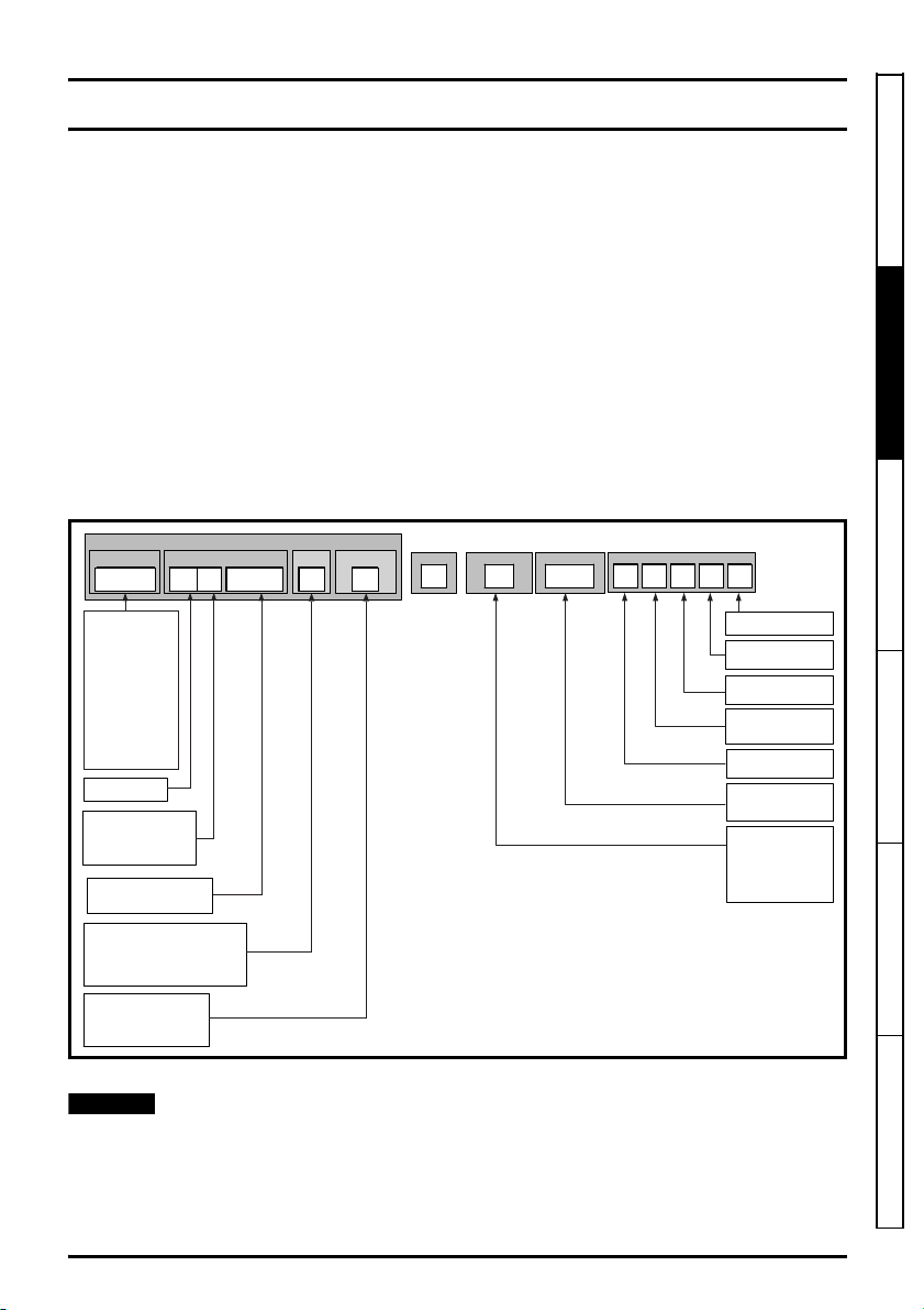
2.2 Model number
The model numbers for the Unidrive M/HS and Commander product range are formed as illustrated
below:
Figure 2-1 Model number
Safety information
Product information
Mechanical installa ion Electrical installa ion Technical data UL lis ing information
* Only shown on frame 9E and 10 identification label
For simplicity a Frame 9 drive with no internal choke (i.e. Model 09xxxxxxE) is referred to as a Frame
9E and a Frame 9 drive with an internal choke (i.e. Model 09xxxxxxA) is referred to as a Frame 9A.
Any reference to Frame 9 is applicable to both sizes 9E and 9A. All Frame size 10 drives are
supplied with no internal choke.
Unidrive M / HS Frame 7 to 10 Power Installation Guide 15
Issue Number: 9
Page 16
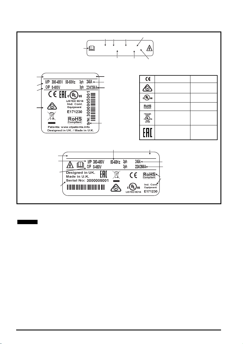
2.3 Nameplate description
M600-094 02240 E10
Model
Frame
Voltage
Heavy Duty
current rating
Power
format
Control pod fitted
Fan power
supply fitted
Refer to
User Guide
Normal/Heavy
Duty power rating
Approvals
Input phases & input current
Output phases & Heavy
Duty/Normal Duty rating
Serial number
Input voltage
Output voltage
Date code
110/132kW 1710
Model
Approvals
Input phases & input current
Output phases & Heavy
Duty/Normal Duty rating
Serial number
Input voltage
Output voltage
Date code
M600-094 02240 E10
110/132kW
1710
Input frequencyInput frequency
Key to approvals
CE approval Europe
RCM regulatory
compliance mark
Australia
UL / cUL approval USA & Canada
RoHS compliant Europe
Functional safety USA & Canada
Eurasian conformity Eurasia
NOTE
Figure 2-2 Typical drive rating labels
Refer to Figure 2-1 Model number on page 15 for further information relating to the labels.
Date code format
The date code is four numbers. The first two numbers indicate the year and the
remaining numbers indicate the week of the year in which the drive was built.
Example:
A date code of 1710 would correspond to week 10 of year 2017.
16 Unidrive M / HS Frame 7 to 10 Power Installation Guide
Issue Number: 9
Page 17
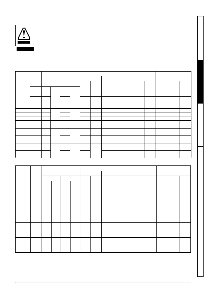
2.4 Ratings
WARNING
NOTE
Fuses
The AC supply to the drive must be installed with suitable protection against overload and
short-circuits. The following section shows recommended fuse ratings. Failure to observe
this requirement will cause risk of fire.
Nominal cables sizes below are based on the cable installation method B2 (ref: IEC603645-52:2001) unless otherwise specified, and are provided as a guide only. Ensure cables
used suit local wiring regulations.
Table 2-1 200 V drive ratings, cable sizes and fuse ratings
Max.
cont.
input
current
Model
3ph Nom
AA A
07200610 67 80
07200750 84 100 100 35 35 1 1 94 22 30 75 18.5 25
07200830 105 125 125 70 70 1/0 1/0 117 30 40 83 22 30
08201160 137 200
08201320 166 200 225 2 x 70 2 x 70 2 x 1 2 x 1 180 45 60 132 37 50
09201760 205 250
09202190 260 315 300
10202830 305 400
10203000 361 450 450
Fuse
IEC UL
Nom
Class
80
gG
200
gR
250
gR
400
gR
Class
CC,
J or T*
HSJ
HSJ
HSJ
Table 2-2 400 V drive ratings, cable sizes and fuse ratings
Max.
cont.
input
current
Model
3ph Nom
AA A
07400660 74 100
07400770 88 100 100 50 50 2 2 94 45 60 77 37 60
07401000 105 125 125 70 70 1/0 1/0 112 55 75 100 45 75
08401340 155 250
08401570 177 250 225 2 x 70 2 x 70 2 x 1/0 2 x 1/0 184 90 150 157 75 125
09402000 232
09402240 267 350
10402700 332 400
10403200 397 450 450
* These fuses are fast acting.
** These ratings are for 2 kHz switching frequency. For ratings at 3 kHz switching frequency refer to the Power and
current ratings in section 5.1.2
temperature)
on page 94.
Fuse
IEC UL
Class
gG
gR
315 gR
gR
Nom
Class
80
225
300
400
Power and current ratings (Derating for switching frequency and
Nominal cable size
European USA
Input Output Input Output
AWG
mm2mm
2 x 70
(B1)
2 x 95
(B1)
2 x 120
(B1)
2 x 150
(C)
Input Output Input Output
mm
CC,
J or
T*
2 x 50 2 x 50 2 x 1 2 x 1 155 75 100 134 55 100
HSJ
2 x 70
(B1)
HSJ
2 x 95
(B1)
2 x 120
(C)
HSJ
2 x 150
(C)
2
3535227518525611520
95 95 3/0 3/0 149 37 50 116 30 40
2 x 95
(B2)
2 x 120
(B2)
2 x 120
(C)
Nominal cable size
European USA
2mm2
35 35 1 1 79 37 60 66 30 50
2 x 95
(B2)
2 x 120
(B2)
2 x 120
(B2)
2 x 150
(B2)
AWG
or
or
kcmil
kcmil
2 x 2/0 216 55 75 176 45 60
2 x 4/0 266 75 100 219 55 75
2 x
2 x 250 325 90 125 283 75 100
300
2 x
2 x 300 360 110 150 300 90 125
300
AWG
AWG
or
kcmil
kcmil
2 x 3/0 2 x 2/0 221 110 150 200** 90 150
2 x 4/0 2 x 4/0 266** 132 200 224** 110 150
2 x 300 2 x 250 320 160 250 270 132 200
2 x 350 2 x 300 361 200 300 320** 160 250
Normal Duty Heavy Duty
Max.
Nom
Motor
Max.
cont.
power
output
current
AkWhp A kWhp
Max.
cont.
output
current
or
AkWhpA kWhp
power
@
@
230 V
230 V
Normal Duty Heavy Duty
Nom
Motor
power
power
@
@
400 V
460 V
cont.
output
current
Max.
cont.
output
current
Nom
power
230 V
Nom
power
400 V
@
@
Motor
power
@
230 V
Motor
power
@
460 V
Safety information
Product information
Mechanical installa ion Electrical installa ion Technical data UL lis ing information
Unidrive M / HS Frame 7 to 10 Power Installation Guide 17
Issue Number: 9
Page 18
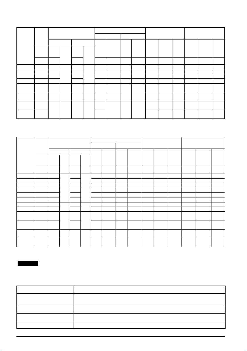
Table 2-3 575 V drive ratings, cable sizes and fuse ratings
NOTE
Max.
cont.
input
current
Model
07500440 45 50
07500550 62 80 80 25 25 3 3 73 55 60 55 37 50
08500630 83 125
08500860 104 160 150 50 50 1 1 108 90 100 86 55 75
09501040 166 150
09501310 166 200 175 HSJ
10501520 197
10501900 218
3ph Nom
AA A
Fuse
IEC UL
Nom
Class
gG
gR
gR
250 gR 250 HSJ
Class
50
CC,
J or T*
100
HSJ
150 HSJ
* These fuses are fast acting.
Nominal cable size
European USA
Input Output Input Output
2mm2
mm
161644534550443040
353511867575634560
2 x 70
(B2)
2 x 70
(B2)
2 x 95
(B2)
AWG AWG A kW hp A kW hp
2 x 35
(B2)
2 x 50
(B2)
2 x 70
(B2)
2 x 3 125 110 125 104 75 100
2 x 1
2 x 1 155 110 150 131 90 125
2 x
2 x
2/0
2/0
Normal Duty Heavy Duty
Max.
Nom
Motor
Max.
cont.
power
@
575 V
power
@
575 V
output
current
200 130 200 152 110 150
200 150 200 190 132 200
cont.
output
current
Nom
power
@
575 V
Table 2-4 690 V drive ratings, cable sizes and fuse ratings
Max.
cont.
input
current
Model
07600190 20 25
07600240 26 32 30 10 10 6 6 30 22 30 24 18 5 25
07600290 31 40 35 10 10 6 6 36 30 40 29 22 30
07600380 39 50 50 16 16 4 4 46 37 50 38 30 40
07600440 44 50 50 16 16 4 4 52 45 60 44 37 50
07600540 62 80 80 25 25 3 3 73 55 75 54 45 60
08600630 83 125
08600860 104 160 150 70 70 1/0 1/0 108 90 125 86 75 100
09601040 149 150
09601310 171 200 200
10601500 202 225 gR
10601780 225 250 gR
3ph Nom
AA A
Fuse
IEC UL
Nom
Class
25
gG
100
gR
150
gR
250 HSJ
Class
* These fuses are fast acting.
Nominal cable size
European USA
Input Output Input Output
2
mm2mm
10 10 8 8 23 18.5 25 19 15 20
CC,
J or
T*
50 50 2 2 86 75 100 63 55 75
HSJ
2 x 50
(B2)
HSJ
2 x 70
(B2)
2 x 70
(B2)
2 x 95
(B2)
AWG AWG A kW hp A kW hp
2 x 35
2 x 1 2 x 3 125 110 150 104 90 125
(B2)
2 x 50
2 x 1/0 2 x 1 155 132 175 131 110 150
(B2)
2 x 2/0 2 x 1/0 172 160 200 150 132 175
2 x 70
(B2)
2 x 3/0 2 x 2/0 197 185 250 178 160 200
Normal Duty Heavy Duty
Max.
Nom
Motor
cont.
output
current
power
@
690 V
power
@
690 V
Max.
cont.
output
current
Nom
power
@
690 V
power
Motor
power
@
575 V
Motor
@
690 V
Refer to Chapter 5.1 Drive technical data on page 92 for maximum fuse rating, maximum
cable size and peak currents.
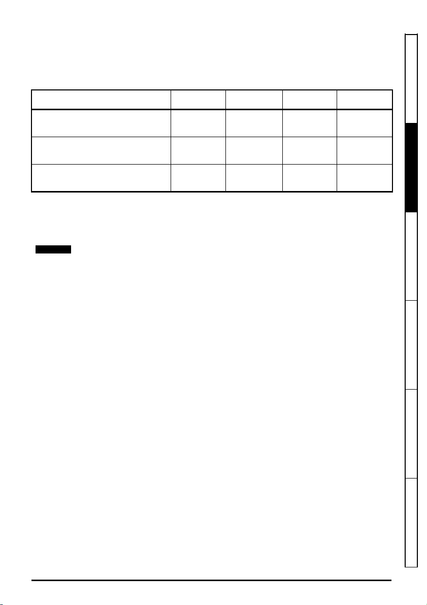
Table 2-5 Protective ground cable ratings
Input phase conductor size Minimum ground conductor size
2
≤ 10 mm
> 10 mm2 and ≤ 16 mm
2
> 16 mm
> 35 mm
and ≤ 35 mm
2
Either 10 mm2 or two conductors of the same cross-sectional area as the input
phase conductor
2
The same cross-sectional area as the input phase conductor
2
16 mm
2
Half of the cross-sectional area of the input phase conductor
18 Unidrive M / HS Frame 7 to 10 Power Installation Guide
Issue Number: 9
Page 19
Typical short term overload limits
NOTE
The maximum percentage overload limit changes depending on the selected motor. Variations in
motor rated current, motor power factor and motor leakage inductance all result in changes in the
maximum possible overload. Typical values are shown in the table below:
Table 2-6 Typical overload limits
Operating mode RFC from cold RFC from 100 %
Normal Duty overload with motor rated
current = Maximum drive normal duty
rated current
Heavy Duty overload with motor rated
current = Maximum drive Heavy duty rated
current (size 8 and below)
Heavy Duty overload with motor rated
current = Maximum drive Heavy duty rated
current (size 9 and 10)
Open loop
from cold
110 % for 165 s 110 % for 9 s 110 % for 165 s 110 % for 9 s
200 % for 28 s 200 % for 3 s 150 % for 60 s 150 % for 7 s
175 % for 42 s 175 % for 5 s 136 % for 81 s 136 % for 11 s
Open loop
from 100 %
Generally the drive rated current is higher than the matching motor rated current allowing a higher
level of overload than the default setting.
The time allowed in the overload region is proportionally reduced at very low output frequency on
some drive ratings.
The maximum overload level which can be attained is independent of the speed.
Output current
The continuous output current ratings given on the rating label are for maximum 40 C (104 F),
1000 m altitude and 3 kHz switching frequency (except where shown). Derating is required for higher
switching frequencies, ambient temperatures >40 C (104 F) and higher altitude. For derating
information, refer to Chapter 5 Technical data on page 92
Input current
The input current is affected by the supply voltage and impedance. The input current given on the
rating label is the typical input current and is stated for a balanced supply.
Safety information
Product information
Mechanical installa ion Electrical installa ion Technical data UL lis ing information
Unidrive M / HS Frame 7 to 10 Power Installation Guide 19
Issue Number: 9
Page 20
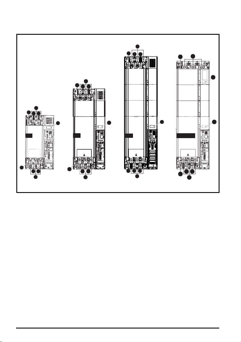
2.5 Drive features
1
2
5
5
1
3
6
7
1
1
2
3
4
5
3
6
7
7
1
2
3
4
5
1
3
6
7
8
1
2
3
4
5
1
3
6
7
9A
9E / 10E
Figure 2-3 Features of the drive (size 7 to 10)- Unidrive M700 shown
Key
1. Ground connec ions 2. AC supply connec ions 3. DC bus + 4. DC bus -
5. Rating label 6. Braking terminal 7. Motor connec ions
20 Unidrive M / HS Frame 7 to 10 Power Installation Guide
Issue Number: 9
Page 21
2.5.1 Items supplied with the drive
The drive is supplied with a copy of the Power Installation Guide and a copy of the Control Getting
Started Guide / Quick Start Guide, a safety information booklet, the Certificate of Quality and an
accessory kit box including the items shown in Table 2-7.
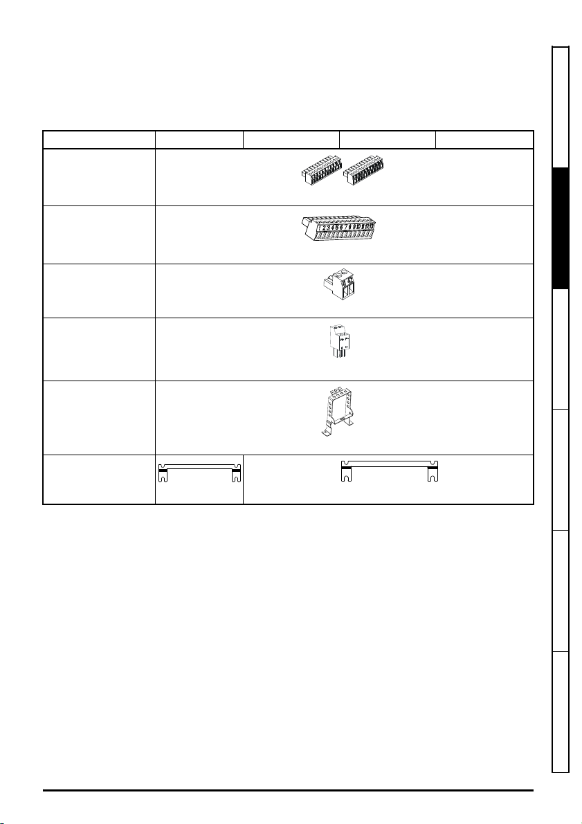
Table 2-7 Parts supplied with the drive
Description Size 7 Size 8 Size 9A / 9E Size 10E
Safety information
Control connectors
(1 to 11 and 21 to 31)
Control connector
(1 to 13)
Relay connector
24 V power supply
connector
Grounding bracket
Surface mounting
brackets
x 2 x 2
* Supplied with Unidrive M700 / M701 / M600 only.
** Supplied with Unidrive M702 only.
*** Supplied with Unidrive M600 to M702 only.
x 1* x 1*
x 1**
x 1***
x 1***
x 1
Product information
Mechanical installa ion Electrical installa ion Technical data UL lis ing information
Unidrive M / HS Frame 7 to 10 Power Installation Guide 21
Issue Number: 9
Page 22

3 Mechanical installation
WARNING
WARNING
WARNING
WARNING
3.1 Safety information
Follow the instructions
The mechanical and electrical installation instructions must be adhered to. Any questions
or doubt should be referred to the supplier of the equipment. It is the responsibility of the
owner or user to ensure that the installation of the drive and any external option unit, and
the way in which they are operated and maintained, comply with the requirements of the
Health and Safety at Work Act in the United Kingdom or applicable legislation and
regulations and codes of practice in the country in which the equipment is used.
Stored charge
The drive contains capacitors that remain charged to a potentially lethal voltage after the
AC supply has been disconnected. If the drive has been energized, the AC supply must
be isolated at least ten minutes before work may continue.
Normally, the capacitors are discharged by an internal resistor. Under certain, unusual
fault conditions, it is possible that the capacitors may fail to discharge, or be prevented
from being discharged by a voltage applied to the output terminals. If the drive has failed
in a manner that causes the display to go blank immediately, it is possible the capacitors
will not be discharged. In this case, consult Nidec Industrial Automation or their authorized
distr butor.
Competence of the installer
The drive must be installed by professional assemblers who are familiar with the
requirements for safety and EMC. The assembler is responsible for ensuring that the end
product or system complies with all the relevant laws in the country where it is to be used.
Enclosure
The drive is intended to be mounted in an enclosure which prevents access except by
trained and authorized personnel, and which prevents the ingress of contamination. It is
designed for use in an environment classified as pollution degree 2 in accordance with IEC
60664-1. This means that only dry, non-conducting contamination is acceptable.
22 Unidrive M / HS Frame 7 to 10 Power Installation Guide
Issue Number: 9
Page 23
3.2 Planning the installation
NOTE
The following considerations must be made when planning the installation:
3.2.1 Access
Access must be restricted to authorized personnel only. Safety regulations which apply at the place
of use must be complied with.
The IP (Ingress Protection) rating of the drive is installation dependent. For further information, refer
to section 3.8 Enclosing standard drive for high environmental protection on page 39.
3.2.2 Environmental protection
The drive must be protected from:
• Moisture, including dripping water or spraying water and condensation. An anti-condensation
heater may be required, which must be switched off when the drive is running.
• Contamination with electrically conductive material
• Contamination with any form of dust which may restrict the fan, or impair airflow over various
components
• Temperature beyond the specified operating and storage ranges
• Corrosive gasses
During installation it is recommended that the vents on the drive are covered to prevent
debris (e.g. wire off-cuts) from entering the drive.
3.2.3 Cooling
The heat produced by the drive must be removed without its specified operating temperature being
exceeded. Note that a sealed enclosure gives much reduced cooling compared with a ventilated one,
and may need to be larger and/or use internal air circulating fans.
For further information, refer to section 3.5 Enclosure for standard drives on page 32.
3.2.4 Electrical safety
The installation must be safe under normal and fault conditions. Electrical installation instructions are
given in Chapter 4 Electrical installation on page 54.
3.2.5 Fire protection
The drive enclosure is not classified as a fire enclosure. A separate fire enclosure must be provided.
For installation in the USA, a NEMA 12 enclosure is suitable.
For installation outside the USA, the following (based on IEC 62109-1, standard for PV inverters) is
recommended.
Enclosure can be metal and/or polymeric, polymer must meet requirements which can be
summarized for larger enclosures as using materials meeting at least UL 94 class 5VB at the point of
minimum thickness.
Air filter assemblies to be at least class V-2.
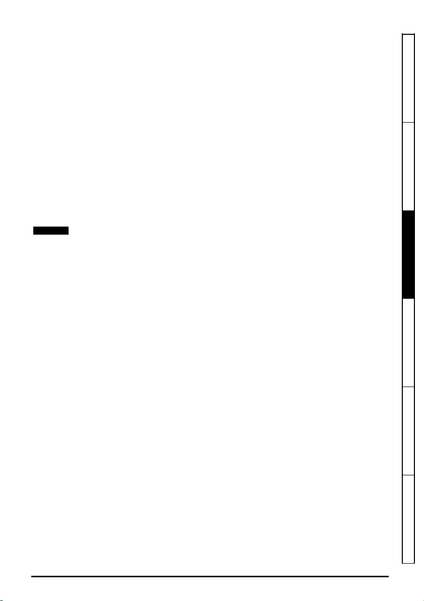
The location and size of the bottom shall cover the area shown in Figure 3-1. Any part of the side
which is within the area traced out by the 5° angle is also considered to be part of the bottom of the
fire enclosure.
Safety information Product information
Mechanical installation
Electrical installa ion Technical data UL lis ing information
Unidrive M / HS Frame 7 to 10 Power Installation Guide 23
Issue Number: 9
Page 24
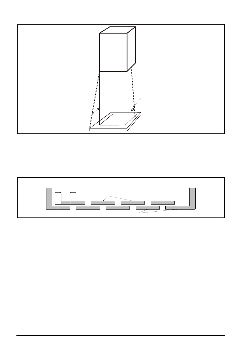
Figure 3-1 Fire enclosure bottom layout
Drive
5
o
5
o
Not less
than 2
times ‘X’
Baffle plates (may be above or
below bottom of enclosure)
Bottom of fire enclosure
X
The bottom, including the part of the side considered to be part of the bottom, must be designed to
prevent escape of burning material - either by having no openings or by having a baffle construction.
This means that openings for cables etc. must be sealed with materials meeting the 5VB
requirement, or else have a baffle above. See Figure 3-2 for acceptable baffle construction. This
does not apply for mounting in an enclosed electrical operating area (restricted access) with concrete
floor.
Figure 3-2 Fire enclosure baffle construction
3.2.6 Electromagnetic compatibility
Variable speed drives are powerful electronic circuits which can cause electromagnetic interference if
not installed correctly with careful attention to the layout of the wiring.
Some simple routine precautions can prevent disturbance to typical industrial control equipment.
If it is necessary to meet strict emission limits, or if it is known that electromagnetically sensitive
equipment is located nearby, then full precautions must be observed. In-built into the drive, is an
internal EMC filter, which reduces emissions under certain conditions. If these conditions are
exceeded, then the use of an external EMC filter may be required at the drive inputs, which must be
located very close to the drives. Space must be made available for the filters and allowance made for
carefully segregated wiring. Both levels of precautions are covered in section 4.11 EMC
(Electromagnetic compatibility) on page 75.
3.2.7 Hazardous areas
The drive must not be located in a classified hazardous area unless it is installed in an approved
enclosure and the installation is certified
24 Unidrive M / HS Frame 7 to 10 Power Installation Guide
Issue Number: 9
Page 25
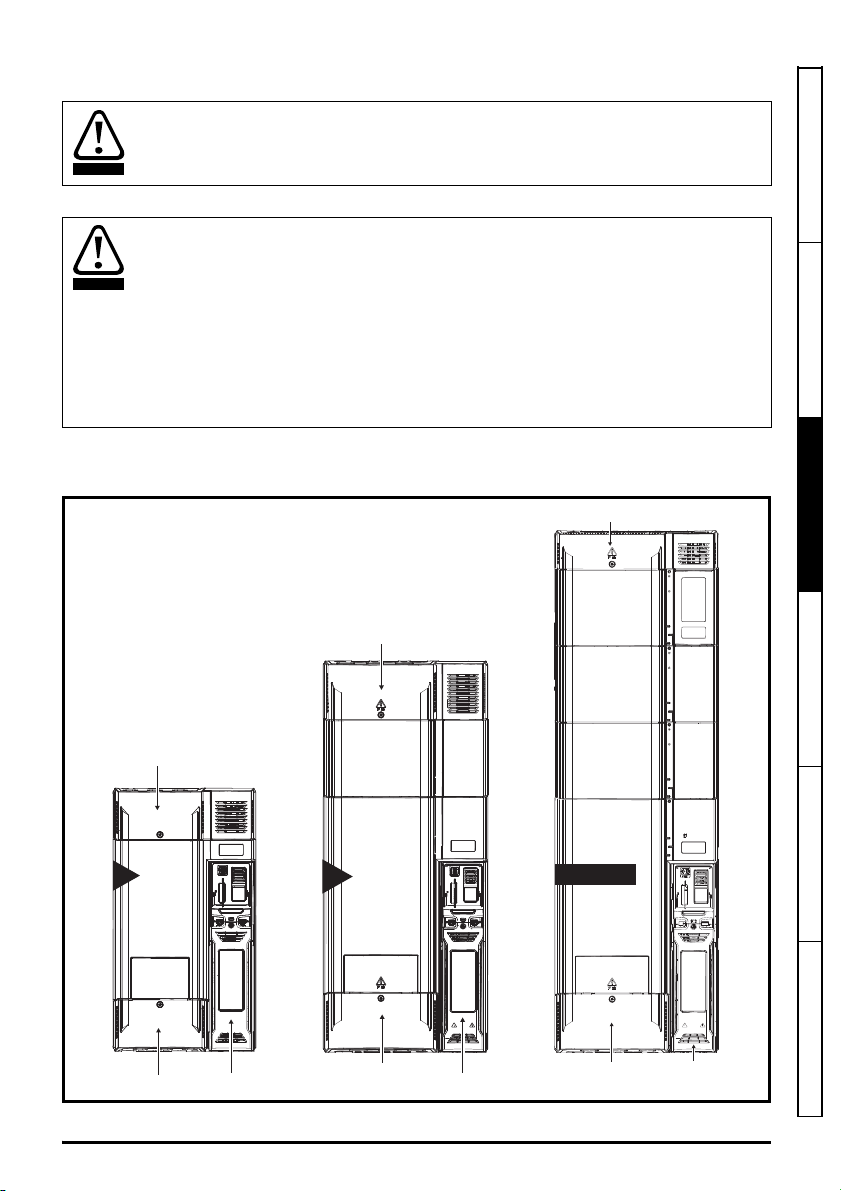
3.3 Terminal cover removal
WARNING
WARNING
7
AC / DC
terminal cover
Motor / Braking
terminal cover
Control terminal
cover
AC
terminal cover
Motor / Braking
terminal cover
Control term nal
cover
9A 9E 10E
AC / DC
terminal cover
Motor / Braking
terminal cover
Control terminal
cover
8
Isolation device
The AC and / or DC power supply must be disconnected from the drive using an approved
isolation device before any cover is removed from the drive or before any servicing work
is performed.
Stored charge
The drive contains capacitors that remain charged to a potentially lethal voltage after the
AC and / or DC power supply has been disconnected. If the drive has been energized,
the power supply must be isolated at least ten minutes before work may continue.
Normally, the capacitors are discharged by an internal resistor. Under certain, unusual
fault conditions, it is possible that the capacitors may fail to discharge, or be prevented
from being discharged by a voltage applied to the output terminals. If the drive has failed
in a manner that causes the display to go blank immediately, it is possible the capacitors
will not be discharged. In this case, consult Nidec Industrial Automation or their authorized
distr butor.
3.3.1 Removing the terminal covers
Figure 3-3 Location and identification of terminal covers
Safety information Product information
Mechanical installation
Unidrive M / HS Frame 7 to 10 Power Installation Guide 25
Issue Number: 9
Electrical installa ion Technical data UL lis ing information
Page 26
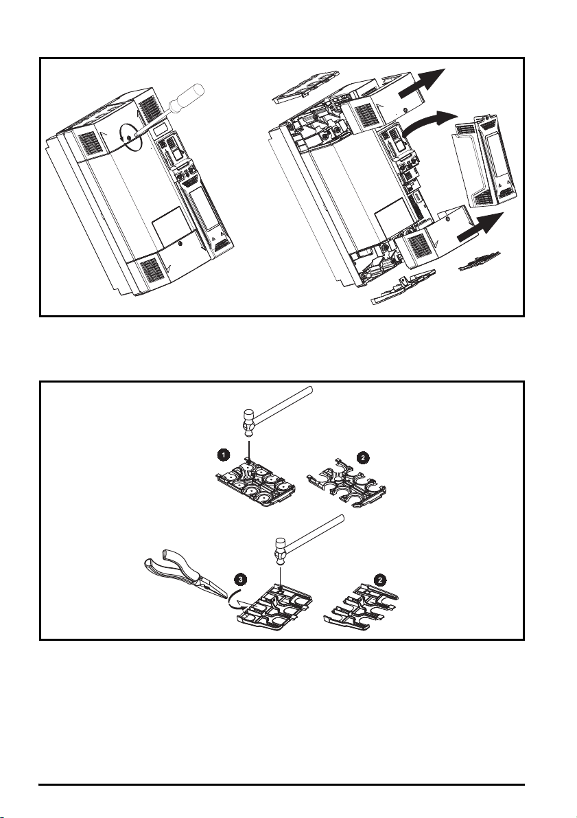
Figure 3-4 Removing the size 7 to 10 terminal covers (Unidrive M600 to M702 size 7 shown)
When replacing the terminal covers, the screws should be tightened to a maximum torque of 1 N m
(0.7 lb ft).
3.3.2 Removing the finger-guard and DC terminal cover break-outs
Figure 3-5 Removing the finger-guard break-outs
All sizes:
Place the finger-guard on a flat solid surface and hit relevant break-outs with hammer as shown (1).
Pliers can be used to remove the breakouts, grasp the relevant break-out with pliers and twist it as
shown (3). Continue until all the required break-outs have been removed (2). Remove any flash /
sharp edges once the break-outs have been removed.
26 Unidrive M / HS Frame 7 to 10 Power Installation Guide
Issue Number: 9
Page 27
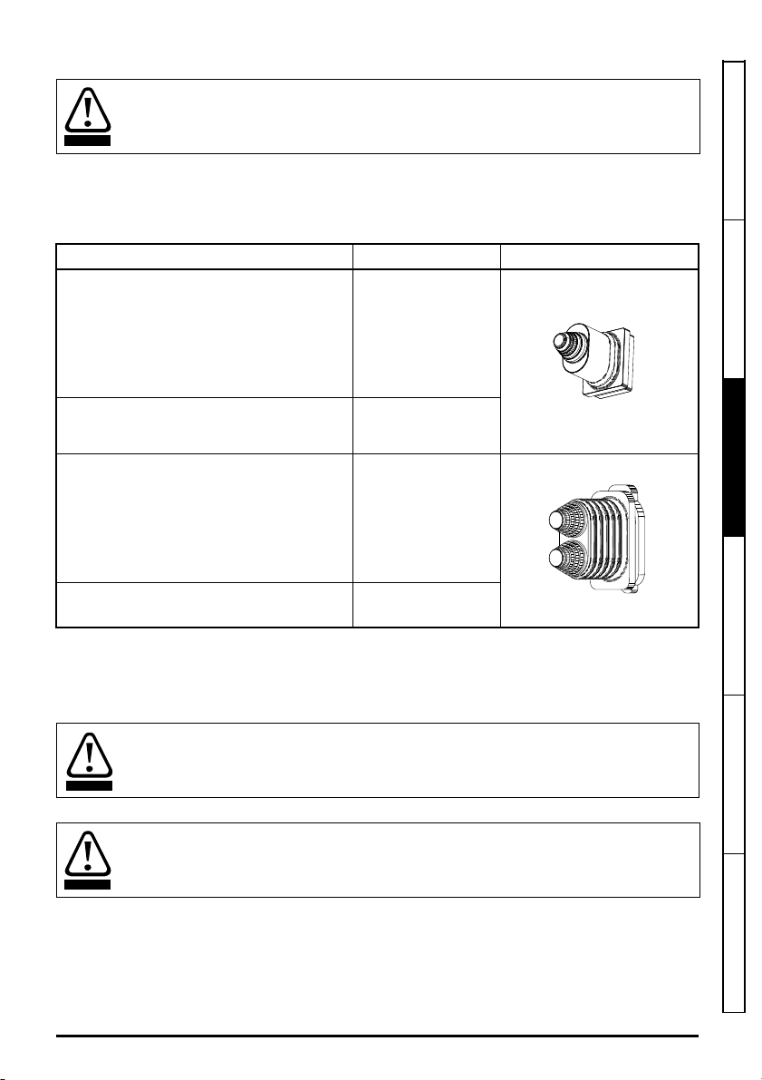
Grommets must be installed to ensure ingress protection to IP20 and to avoid the risk of
WARNING
WARNING
WARNING
fire in the event of a major internal failure.
Grommet kits are available for size 7 to 10 finger guards. For size 8 to 10, two versions are available
allowing for either single or double cable entries.
Table 3-1 Grommet kits
Drive size Part number Picture
Size 7 - Kit of 8 x single entry grommets 3470-0086
Size 8 - Kit of 8 x single entry grommets 3470-0089
Size 8 - Kit of 8 x double entry grommets 3470-0090
Safety information Product information
Mechanical installation
Electrical installa ion Technical data UL lis ing information
Size 9 and 10 - Kit of 8 x double entry
grommets
3470-0107
3.4 Dimensions and mounting methods
Drive sizes 7 to 10 can be either surface or through-panel mounted using the appropriate brackets.
If the drive has been used at high load levels for a period of time, the heatsink can reach
temperatures in excess of 70 °C (158 °F). Human contact with the heatsink should be
prevented.
Many of the drives in this product range weigh in excess of 15 kg (33 b). Use appropriate
safeguards when lifting these models.
A full list of drive weights can be found in Table 5-14 Overall drive weights on page 106.
Unidrive M / HS Frame 7 to 10 Power Installation Guide 27
Issue Number: 9
Page 28
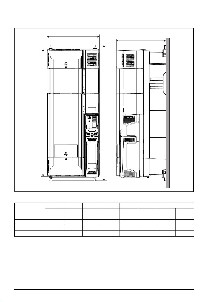
3.4.1 Drive dimensions
W
D
H2
H1
Figure 3-6 Drive dimensions (Unidrive M700 size 8 shown)
H1 H2 W D
mm in mm in mm in mm in
Size
7 557 21.93 508 20 270 10.63 280 11.02
8 804 31.65 753 29.65 310 12.21 290 11.42
9E and 10E 1069 42.09 1010 39.70 310 12.21 290
9A 1108 43.61 1049 41.30 310 12.21 290 11.42
28 Unidrive M / HS Frame 7 to 10 Power Installation Guide
11. 42
Issue Number: 9
Page 29
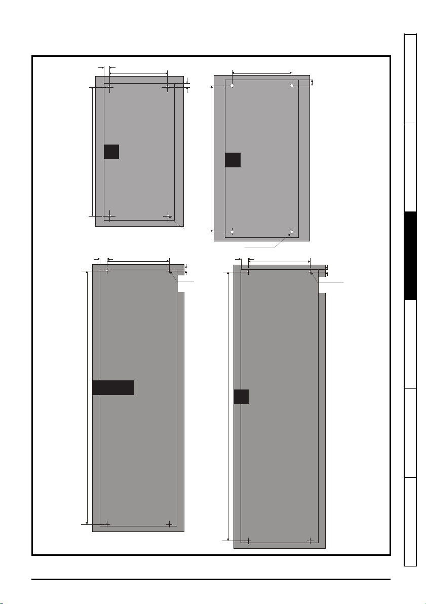
3.4.2 Surface mounting
220 mm (8.66 in)
Æ
9mm (0.35 in)
538 mm (21 18)
25 mm
(0.98 in)
10 mm
(0.39 in)
784 mm (30.87 in)
259 mm (10.20 in)
(0.35 in)
x 4 holes
9 mm
(0.35 in)
26 mm
(1.02 in)
Æ
9.0 mm
9.5 mm
(0.37 in)
259 mm (10.20 in)
(0.35 in)
x 4 holes
9 mm
(0.35 in)
26 mm
(1.02 in)
Æ
9.0 mm
1090 mm (42 91 in)
9.0 mm (0.35 in)
x 4 holes
Æ
259 mm (10.20 in)
1051 mm (41 38 in)
7
8
9E / 10E
9A
Figure 3-7 Surface mounting dimensions (size 7 to 10)
Safety information Product information
Mechanical installation
Electrical installa ion Technical data UL lis ing information
Unidrive M / HS Frame 7 to 10 Power Installation Guide 29
Issue Number: 9
Page 30
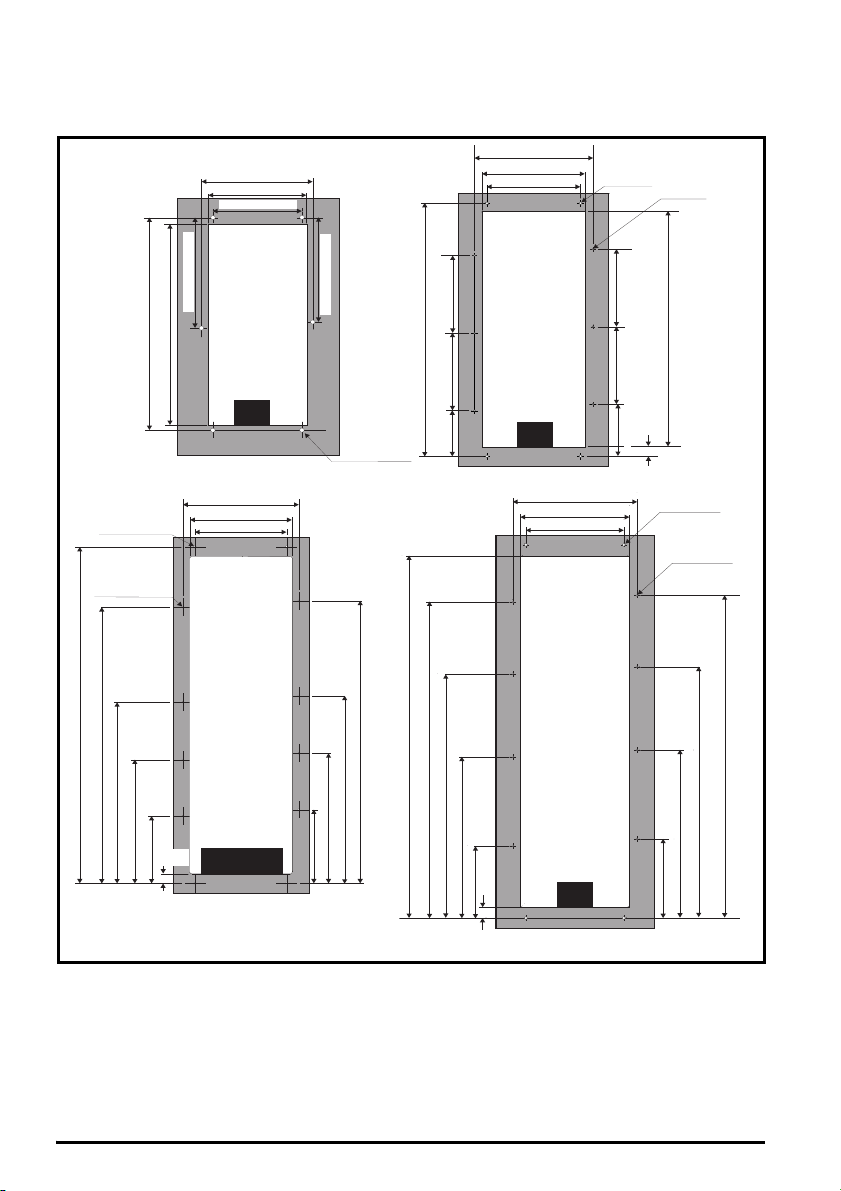
3.4.3 Through-panel mounting
310 mm (12 20 in)
252 mm (9 92 in)
220 mm (8 66 in)
Æ9 mm (0 35 in)
x 6 holes
278 mm (10.95 in)
488 mm (19.21 in)
538 mm (21.18 in)
328 mm (12 91 in)
287±1 mm (11 3±0 04 in)
259 mm (10 20 in)
794 mm (31.26 in)
730 mm (28.74 in)
240 mm (9.45 in)
240 mm (9.45 in)
146 mm
(5.75 in)
Æ9 mm (0 35 in)
(4 holes)
166 mm
(6.54 in)
240 mm (9.45 in)
240 mm (9.45 in)
32 mm
(1 26 in)
Æ5 mm (0 21 in)5
(6 holes)
252 mm (9.92 in)
259 mm (10 20 in)
287±1 mm (11 3±0 04 in)
327 mm (12 87 in)
883 mm (34.76 in)
586 mm (23.07 in)
406 mm (15.98 in)
231 mm (9.09 in)
Æ
9 0 mm (0 35 in)
x 4 holes
Æ
5 5 mm (0 22 in)
x 8 holes
1051 mm (41.38 in)
863 mm (33.98 in)
566 mm (22.28 in)
386 mm (15.20 in)
211 mm (8.31 in)
31 mm
(1 22 in)
328 mm (12 90 in)
287±1 mm (11 3±0 04 in)
259 mm (10 18 in)
Æ9 mm (0 35 in)
x 4 holes
Æ5 mm (0 21 in)5
x 8 holes
1058 mm (41.66 in)
923 mm (36.33 in)
714 mm (28.10 in)
471 mm (18.54 in)
211 mm (8.30 in)
32 mm
(1 24 in)
231 mm (9.09 in)
491 mm (19.32 in)
734 mm (28.89 in)
942 mm (37.08 in)
7
8
9E/10E
9A
The drive can be through panel mounted using appropriate brackets.
Figure 3-8 Through-panel mounting dimensions (size 7 to 10)
30 Unidrive M / HS Frame 7 to 10 Power Installation Guide
Issue Number: 9
Page 31

3.4.4 Mounting brackets
WARNING
Table 3-2 Mounting brackets
Frame size
7
Surface mounting kit
(supplied with drive)
Qty
x 2*
Optional through-panel
mounting kit
Hole size: 9 mm (0.35 in)
Safety information Product information
Qty
x 2
Hole size: 9 mm (0.35 in)
x 1
x 6
8
Hole size: 9 mm (0.35 in)
9A / 9E and
10E
Hole size: 9 mm (0.35 in)
x 2*
x 2*
Hole size: 5.5 mm (0.22 in)
x 1
x 8
Hole size: 5.5 mm (0.22 in)
x 1
* Surface mounting bracket are also used when through-panel mounting.
The through panel mounting kit is not supplied with the drive and can be purchased separately, below
are the relevant part numbers:
Size CT part number
7 3470-0079
8 3470-0083
9A 3470-0119
9E/10E 3470-0105
If the drive has been used at high load levels for a period of time, the heatsink can reach
temperatures in excess of 70 °C (158 °F). Human contact with the heatsink should be
prevented.
Mechanical installation
Electrical installa ion Technical data UL lis ing information
Unidrive M / HS Frame 7 to 10 Power Installation Guide 31
Issue Number: 9
Page 32

3.5 Enclosure for standard drives
Enclosure
A
NOTE
3.5.1 Recommended spacing between the drives
Figure 3-9 Recommended spacing between the drives
Table 3-3 Spacing required between the drives
Drive Size
7 30 mm (1.18 in)
8 30 mm (1.18 in)
9A/E 60 mm (2.37 in)
10E 60 mm (2.37in)
* 50°C derating applies, refer to Table 5-6 Maximum permissible continuous output current @ 50 °C
(122 °F) on page 96.
40°C 50°C*
Spacing (A)
When through-panel mounted, ideally drives should be spaced at least 45 mm (1.77 in) to
maximize panel stiffness
32 Unidrive M / HS Frame 7 to 10 Power Installation Guide
Issue Number: 9
Page 33

3.5.2 Enclosure layout
Ensure minimum clearances
are maintained for the drive
and external EMC filter Forced
or convection air flow must not
be restricted by any object or
cabling
Note
For EMC compliance
1) When using an external EMC
filter, one filter is required for
each drive
2) Power cabling must be at
least 100mm (4in) from the
drive in all directions
A
B
60mm (2 37 in)
30mm (1 18 in)
Optional brak ng
resistor and overload
Locate opt onal braking
resistor external to
cubicle (preferably near
to or on top of the cubicle)
Locate the overload
protection device as required
AC supply
contactor and
fuses or MCB
Locate as
required
Enclosure
³ 100 mm
(4 n)
A
controller
External
Signal cables
Plan for all signal cables
to be routed at least
300 mm (12 in) from the
drive and any power cable
³ 100 mm
(4 n)
B
B
³ 100 mm
(4 in)
7 8
NOTE
Please observe the clearances in the diagram below taking into account any appropriate notes for
other devices / auxiliary equipment when planning the installation.
Figure 3-10 Enclosure layout (size 7 to 8)
Safety information Product information
For EMC compliance:
1.
When using an external EMC filter, one filter is required for each drive.
2.
Power cabling must be at least 100 mm (4 in) from the drive in all directions
Mechanical installation
Electrical installa ion Technical data UL lis ing information
Unidrive M / HS Frame 7 to 10 Power Installation Guide 33
Issue Number: 9
Page 34

Figure 3-11 Enclosure layout (size 9 to 10)
Ensure minimum clearances
are maintained for the drive
and external EMC filter Forced
or convection air flow must not
be restricted by any object or
cabling
Note
For EMC compliance
1) When using an external EMC
filter, one filter is required for
each drive
2) Power cabling must be at
least 100mm (4in) from the
drive in all directions
A
B
60 mm (2 37 in)
45 mm (1 77 in)
B B
A
AC supply
contactor and
fuses or MCB
Locate as
required
Enclosure
³100mm
(4in)
³100mm
(4in)
Signal cables
Plan for all signal cables
to be routed at least
300 mm (12 in) from the
drive and any power cable
controller
External
Optional braking
resistor and overload
Locate optional braking
resistor external to
cubicle (preferably near
to or on top of the cubicle)
Locate the overload
protection device as required
9 10
34 Unidrive M / HS Frame 7 to 10 Power Installation Guide
Issue Number: 9
Page 35

3.5.3 Enclosure sizing
A
e
P
kT
intText
–
-----------------------------------
=
NOTE
1. Add the dissipation figures from section 5.1.3 Power dissipation on page 98 for each drive that is
to be installed in the enclosure.
2. If an external EMC filter is to be used with each drive, add the dissipation figures from section
3.9.2 EMC filter ratings on page 44 for each external EMC filter that is to be installed in the
enclosure.
3. If the braking resistor is to be mounted inside the enclosure, add the average power figures from
for each braking resistor that is to be installed in the enclosure.
4. Calculate the total heat dissipation (in Watts) of any other equipment to be installed in the
enclosure.
5. Add the heat dissipation figures obtained above. This gives a figure in Watts for the total heat that
will be dissipated inside the enclosure.
Calculating the size of a sealed enclosure
The enclosure transfers internally generated heat into the surrounding air by natural convection (or
external forced air flow); the greater the surface area of the enclosure walls, the better is the
dissipation capability. Only the surfaces of the enclosure that are unobstructed (not in contact with a
wall or floor) can dissipate heat.
Calculate the minimum required unobstructed surface area A
Where:
Unobstructed surface area in m2 (1 m2 = 10.9 ft2)
A
e
T
Maximum expected temperature in
ext
Maximum permiss ble temperature in oC inside the enclosure
T
int
o
C outside the enclosure
P Power in Watts dissipated by all heat sources in the enclosure
k Heat transmission coefficient of the enclosure material in W/m
Example
To calculate the size of an enclosure for the following:
• Two drives operating at the Normal Duty rating
• External EMC filter for each drive
• Braking resistors are to be mounted outside the enclosure
• Maximum ambient temperature inside the enclosure: 40 C
• Maximum ambient temperature outside the enclosure: 30 C
For example, if the power dissipation from each drive is 187 W and the power dissipation from each
external EMC filter is 9.2 W.
Total dissipation: 2 x (187 + 9.2) =392.4 W
for the enclosure from:
e
2/o
C
Safety information Product information
Mechanical installation
Electrical installa ion Technical data UL lis ing information
Power dissipation for the drives and the external EMC filters can be obtained from
Chapter 5 Technical data on page 92.
The enclosure is to be made from painted 2 mm (0.079 in) sheet steel having a heat
2/o
transmission coefficient of 5.5 W/m
C. Only the top, front, and two sides of the
enclosure are free to dissipate heat.
2
The value of 5.5 W/m
/ºC can generally be used with a sheet steel enclosure (exact
values can be obtained by the supplier of the material). If in any doubt, allow for a greater
margin in the temperature rise.
Unidrive M / HS Frame 7 to 10 Power Installation Guide 35
Issue Number: 9
Page 36

W
H
D
A
e
392.4
5.5 40 30–
--------------------------------
=
W
A
e
2HD–
HD+
-------------------------
=
W
7.135 2 2 0.6–
20.6+
--------------------------------------------------- -
=
V
3kP
T
intText
–
---------------------------
=
Figure 3-12 Enclosure having front, sides and top panels free to dissipate heat
Insert the following values:
T
40 C
int
T
30 C
ext
k 5.5
P 392.4 W
The minimum required heat conducting area is then:
2
= 7.135 m
(77.8 ft2) (1 m2 = 10.9 ft2)
Estimate two of the enclosure dimensions - the height (H) and depth (D), for instance. Calculate the
width (W) from:
Inserting H = 2 m and D = 0.6 m, obtain the minimum width:
=1.821 m (71.7 in)
If the enclosure is too large for the space available, it can be made smaller only by attending to one
or all of the following:
• Using a lower PWM switching frequency to reduce the dissipation in the drives
• Reducing the ambient temperature outside the enclosure, and/or applying forced-air cooling to
the outside of the enclosure
• Reducing the number of drives in the enclosure
• Removing other heat-generating equipment
Calculating the air-flow in a ventilated enclosure
The dimensions of the enclosure are required only for accommodating the equipment. The
equipment is cooled by the forced air flow.
Calculate the minimum required volume of ventilating air from:
36 Unidrive M / HS Frame 7 to 10 Power Installation Guide
Issue Number: 9
Page 37

Where:
P
o
P
l
------
V
31.3 323.7
40 30–
------------------------------------- -
=
3
V Air-flow in m
T
Maximum expected temperature in C outside the enclosure
ext
Maximum permiss ble temperature in C inside the enclosure
T
int
per hour (1 m3/hr = 0.59 ft3/min)
P Power in Watts dissipated by all heat sources in the enclosure
k Ratio of
Where:
P
is the air pressure at sea level
0
P
is the air pressure at the installation
I
Typically use a factor of 1.2 to 1.3, to allow also for pressure-drops in dirty air-filters.
Example
To calculate the size of an enclosure for the following:
• Three drives operating at the Normal Duty rating
• External EMC filter for each drive
• Braking resistors are to be mounted outside the enclosure
• Maximum ambient temperature inside the enclosure: 40 C
• Maximum ambient temperature outside the enclosure: 30 C
For example, dissipation of each drive: 101 W and dissipation of each external EMC filter: 6.9 W
(max).
Total dissipation: 3 x (101 + 6.9) = 323.7 W
Insert the following values:
T
40 C
int
T
30 C
ext
k 1.3
P 323.7 W
Then:
Safety information Product information
Mechanical installation
Electrical installa ion Technical data UL lis ing information
3
= 126.2 m
Unidrive M / HS Frame 7 to 10 Power Installation Guide 37
Issue Number: 9
/hr (74.5 ft3 /min) (1 m3/ hr = 0.59 ft3/min)
Page 38

3.6 Enclosure design and drive ambient temperature
Drive derating is required for operation in high ambient temperatures
Totally enclosing or through panel mounting the drive in either a sealed cabinet (no airflow) or in a
well ventilated cabinet makes a significant difference on drive cooling.
The chosen method affects the ambient temperature value (T
) which should be used for any
rate
necessary derating to ensure sufficient cooling for the whole of the drive.
The ambient temperature for the four different combinations is defined below:
1. Totally enclosed with no air flow (<2 m/s) over the drive
= T
T
rate
+ 5 °C
int
2. Totally enclosed with air flow (>2 m/s) over the drive
T
= T
rate
int
3. Through panel mounted with no airflow (<2 m/s) over the drive
T
= the greater of T
rate
+5 °C, or T
ext
int
4. Through panel mounted with air flow (>2 m/s) over the drive
T
= the greater of T
rate
ext
or T
int
Where:
T
= Temperature outside the cabinet
ext
= Temperature inside the cabinet
T
int
= Temperature used to select current rating from tables in Chapter 5 Technical data on
T
rate
page 92.
3.7 Heatsink fan operation
The drive is ventilated by an internal heatsink mounted fan. The fan housing forms a baffle plate,
channelling the air through the heatsink chamber. Thus, regardless of mounting method (surface
mounting or through-panel mounting), the installing of additional baffle plates is not required.
Ensure the minimum clearances around the drive are maintained to allow air to flow freely.
The heatsink fan on all sizes is a variable speed fan. The drive controls the speed at which the fan
runs based on the temperature of the heatsink and the drive's thermal model system. The maximum
speed at which the fan operates can be limited in Pr 06.045. This could incur an output current
derating. Size 7 to 10 are also fitted with a variable speed fan to ventilate the capacitor bank. Refer to
section 3.11 Routine maintenance on page 49 for information on fan removal.
38 Unidrive M / HS Frame 7 to 10 Power Installation Guide
Issue Number: 9
Page 39

3.8 Enclosing standard drive for high environmental protection
Drive
Gasket
Enclosure
rear wall
An explanation of environmental protection rating is provided in section 5.1.9 IP / UL Rating on
page 102.
The standard drive is rated to IP20 pollution degree 2 (dry, non-conductive contamination only)
(NEMA 1). However, it is possible to configure the drive to achieve IP65 rating (size 7 and 8) or IP55
(size 9 and 10) (NEMA 12) at the rear of the heatsink for through-panel mounting.
This allows the front of the drive, along with various switchgear, to be housed in a high IP enclosure
with the heatsink protruding through the panel to the external environment. Thus, the majority of the
heat generated by the drive is dissipated outside the enclosure maintaining a reduced temperature
inside the enclosure. This also relies on a good seal being made between the heatsink and the rear
of the enclosure using the gasket and securing brackets provided.
The main gasket should be installed as shown in Figure 3-13.
Figure 3-13 Installing the gasket
Safety information Product information
Mechanical installation
Electrical installa ion Technical data UL lis ing information
Unidrive M / HS Frame 7 to 10 Power Installation Guide 39
Issue Number: 9
Page 40

A special procedure is necessary when through hole mounting size 7 in a high IP enclosure to move
1
2
3
4
an EMC bracket that would otherwise prevent a good seal. This procedure is described in Figure 3-
14.
Figure 3-14 Special procedure for size 7 only
1) Remove screw shown using T20 torque driver
2) Bend EMC bracket 90 degrees as shown
3) Fit sealing gasket and place drive in panel cutout
4) Ensure EMC bracket is trapped under lower mounting bracket when fitting brackets
40 Unidrive M / HS Frame 7 to 10 Power Installation Guide
Issue Number: 9
Page 41

Figure 3-15 Example of high IP through-panel layout
IP20
(NEMA1)
IP55 (NEMA 12)
or IP65 enclosure
The providesGasket seal
an IP65 (size 7 and 8) or
IP55 (size 9 and 10)
rated barrier to maintain
enclosure rating after
drive is fitted.
NOTE
The main gasket should be installed as shown in Figure 3-13. Any screws / bolts that are used for
mounting should be installed with M8 flat nylon washers to maintain a seal around the screw hole.
See Figure 3-16 on page 42, sealing clamps are supplied in the through panel mounting kit to aid
compression of the gasket.
Safety information Product information
Mechanical installation
Electrical installa ion Technical data UL lis ing information
The heatsink fans have conformal coated PCBs and have sealant at cable entry points.
Dripping, splashing or sprayed water can impede the operation of the fan, therefore if the
environment is such that the fan may be subjected to more than occasional dripping or
sprayed water while operational, then suitable drip protection covers should be employed.
Unidrive M / HS Frame 7 to 10 Power Installation Guide 41
Issue Number: 9
Page 42

Figure 3-16 View showing sealing clamps provided in through hole mounting kit
Enclosure
rear wall
Sea ing
brackets
NOTE
NOTE
For detailed information regarding high IP through panel mounting see section
3.4.3 Through-panel mounting on page 30.
When designing a high IP enclosure, consideration should be given to the dissipation from
the front of the drive.
Table 3-4 Power losses from the front of the drive when through-panel mounted
Frame size Power loss
7 204 W
8 347 W
9A/9E/10E 480 W
42 Unidrive M / HS Frame 7 to 10 Power Installation Guide
Issue Number: 9
Page 43

3.9 External EMC filter
The external EMC filters for sizes 7 to 10, are designed to be mounted above the drive as shown
below.
Figure 3-17 Size 7 to 10 mounting of the EMC filter
3.9.1 Optional external EMC filters
Table 3-5 EMC filter cross reference
Model CT part number
200 V
07200610 to 07200830 4200-1132
08201160 to 08201320 4200-1972
09201760 to 09202190 (9A) 4200-3021
09201760 to 09202190 (9E) 4200-4460
10202830 to 10203000 4200-4460
400 V
07400660 to 07401000 4200-1132
08401340 to 08401570 4200-1972
09402000 to 09402240 (9A) 4200-3021
09402000 to 09402240 (9E) 4200-4460
10402700 to 10403200 4200-4460
575 V
07500440 to 07500550 4200-0672
08500630 to 08500860 4200-1662
09501040 to 09501310 (9A) 4200-1660
09501040 to 09501310 (9E) 4200-2210
10501520 to 10501900 4200-2210
690 V
07600190 to 07600540 4200-0672
08600630 to 08600860 4200-1662
09601040 to 09601310 (9A) 4200-1660
09601040 to 09601310 (9E) 4200-2210
10601500 to 10601780 4200-2210
Safety information Product information
Mechanical installation
Electrical installa ion Technical data UL lis ing information
Unidrive M / HS Frame 7 to 10 Power Installation Guide 43
Issue Number: 9
Page 44

3.9.2 EMC filter ratings
Table 3-6 Optional external EMC filter details
Maximum
continuous
current
CT part
number
4200-1132 117 102.7* 528 480
4200-0672 67 58.8* 759 600 25 21.9 24.5 395 2.72
4200-1972 197 172.8* 528 480 42 36.7 18.7 210 1.68
4200-1662 114 100* 759 600 39 34.1 24.3 364 2.72
4200-3021 302 277 528 480
4200-1660 166 152 759 600 13 11.4 21 332 2.72
4200-4460 446 409 528 480 37 32.4 30 283 1.68
4200-2210 221 203 759 600 16 14.0 21 434 2.72
(104 °F)
@ 50 °C
(122 °F)
A A V V W W mA mA M
Voltage
rating
IEC UL
IP
rating
20
00
Power dissipation
at rated current
@ 40 °C
(104 °F)
@ 50 °C
(122 °F)
50 43.7 11.7 188 1.68
34 29.7 30 202 1.68
* At 55 °C (131 °F).
3.9.3 Overall EMC filter dimensions
Table 3-7 Optional external EMC filter dimensions
Dimensions (mm)
Part Number
4200-1132 270 10.63 90 3.54 150 5.90 6 13.2
4200-0672 270 10.63 90 3.54 150 5.90 6.2 13.7
4200-1972 300 11.81 120 4.72 170 6.69 9.6 21.2
4200-1662 300 11.81 120 4.72 170 6.69 9.4 20.7
4200-3021 339 13.3 230 9.06 120 4.72 11 24.3
4200-1660 360 14.2 245 9.6 105 4.13 5.2 11.5
4200-4460 105 4.13 360 14.2 245 9.6 12 26.5
4200-2210 105 4.13 360 14.2 245 9.6 10.3 22.7
HW D
mm inch mm inch mm inch kg lb
Ground leakage
Balanced
supply
phase-to-
phase and
phase-to-
ground
Worst
case@ 40 °C
Discharge
Weight
resistors
44 Unidrive M / HS Frame 7 to 10 Power Installation Guide
Issue Number: 9
Page 45

Figure 3-18 External EMC filter (size 7 to 8)
F
D
V
V
Z
B
L1 L2 L3
L1 L2 L3
Load Line
W
C
A
H
Table 3-8 Size 7 external EMC filter dimensions
CT part
number
4200-1132
4200-0672
ABCDEFHWVXYZ
240 mm
(9.45 in)
255 mm
(10 04 in)
55 mm
(2.17 in)
150 mm
(5 90 in)
205 mm
(8.07 in)
270 mm
(10.63 in)
90 mm
(3 54 in)
M10
6.5 mm
(0.26 in)
Safety information Product information
Mechanical installation
Electrical installa ion Technical data UL lis ing information
Table 3-9 Size 8 external EMC filter dimensions
CT part
number
4200-1972
4200-1662
ABCDEFHWVXYZ
260 mm
(10.24 in)
275 mm
(10.83 in)
85 mm
(3 35 in)
170 mm
(6.69 in)
249 mm
(9.79 in)
300 mm
(11.81 in)
120 mm
(4.72 in)
M10
Unidrive M / HS Frame 7 to 10 Power Installation Guide 45
Issue Number: 9
6.5 mm
(10.26 in)
Page 46

Figure 3-19 External EMC filter (size 9A)
F
J
J
V: Ground stud - M10
Y: O 10.5 mm
Z: O 10.8 mm
D
W
H
Table 3-10 Size 9A external EMC filter dimensions
CT part
number
4200-3021
4200-1660
ABDE FGH I JW
220 mm
(8 66 in)
280 mm
(11.02 in)
170 mm
(6.70 in)
180 mm
(7 09 in)
120 mm
(4.72 in)
105 mm
(4.13 in)
210 mm
(8.27 in)
225 mm
(8.86 in)
2 mm
(0.08 in)
2 mm
(0.08 in)
40 mm
(1.57 in)
40 mm
(1.57 in)
339 mm
(13.34)
360 mm
(14.17 in)
73 mm
(2.87 in)
73 mm
(2.87 in)
60 mm
(2.36 in)
60 mm
(2.36 in)
46 Unidrive M / HS Frame 7 to 10 Power Installation Guide
Issue Number: 9
230 mm
(9.06 in)
245 mm
(9.65 in)
Page 47

Figure 3-20 External EMC filter (size 9E and 10E)
V: Ground stud - M10
Z: O 11 mm
Table 3-11 Size 9E and 10E external EMC filter dimensions
CT part
number
4200-4460
4200-2210
ABCDEGHWY
280 mm
(11.02)
180 mm
(7.09)
57 mm
(2.24 mm)
245 mm
(9.65 in)
225 mm
(8.86 in)
(1.57 in)
40 mm
105 mm
(4.13 in)
360 mm
(14.7 in)
11 m m
(0.43 in)
Safety information Product information
Mechanical installation
Electrical installa ion Technical data UL lis ing information
3.9.4 EMC filter torque settings
Table 3-12 Optional external EMC Filter terminal data.
Power
CT part
number
4200-1132
4200-0672
4200-1972
4200-1662
Bar hole diameter Max cable size Max torque
N/A
connections
50 mm
(1/0 AWG)
95 mm
(3/0 AWG)
Ground stud
2
2
8.0 N m
(6 0lb ft)
20 N m
(14.8 lb ft)
4200-3021 10.8 mm
4200-1660 10.8 mm
4200-4460 11 mm
N/A
30 N m
(22.1 lb ft)
4200-2210 11 mm
Unidrive M / HS Frame 7 to 10 Power Installation Guide 47
Issue Number: 9
size
M10
Ground
connections
Max torque
18 N m
(13.3 lb ft)
Page 48

3.10 Terminal size and torque settings
Table 3-13 Drive control terminal data
Model Connection type Torque setting
M200 to M400 Screw terminals 0.2 N m (0.15 lb ft)
M600 to M702 Plug-in terminal block 0.5 N m (0.4 lb ft)
Table 3-14 Drive relay terminal data
Model Connection type Torque setting
M200 to M400 Screw terminals
M600 to M702 Plug-in terminal block
Table 3-15 Terminal block maximimum cable sizes
Model
All All Control connector
All All 2 way relay connector
M300 to M400 7 to 9 STO connector
M600 to M702 All
Size Terminal block description Maximum cable size
2 way low voltage power 24V supply
connector
Table 3-16 Maximum crimp/lug sizes for frame size 8 to 10
Terminals
AC supply connections 2 x 185 2 x 500
AC supply ground 2 x 120 1 x 350
Motor connections 2 x 150 2 x 350
Drive output ground 2 x 150 1 x 350
Brake connection 2 x 150 2 x 350
Maximum standard crimp (mm
0.5 N m (0.4 lb ft)
1.5 mm
2.5 mm
1.5 mm
Maximum standard US lug
2
)
2
(16 AWG)
2
(14 AWG)
2
(16 AWG)
(kcmil)
Table 3-17 Drive power terminal data
Model
size
7
8 to 10
AC and motor terminals DC and braking Ground terminal
Recommended Maximum Recommended Maximum Recommended Maximum
M8 Nut (13 mm AF) M8 Nut (13 mm AF) M8 Nut (13 mm AF)
12 N m
(8.85 lb ft)
M10 Nut (17 mm AF) M10 Nut (17 mm AF) M10 Nut (17 mm AF)
15 N m
(11.1 Ib ft)
14 N m
(10 lb ft)
20 N m
(14 8 Ib ft)
12 N m
(8.85 lb ft)
15 N m
(11.1 Ib ft)
14 N m
(10 lb ft)
20 N m
(14.8 Ib ft)
12 N m
(8.85 lb ft)
15 N m
(11.1 Ib ft)
14 N m
(10 lb ft)
20 N m
(14.8 Ib ft)
48 Unidrive M / HS Frame 7 to 10 Power Installation Guide
Issue Number: 9
Page 49

3.11 Routine maintenance
The drive should be installed in a cool, clean, well ventilated location. Contact of moisture and dust
with the drive should be prevented.
Regular checks of the following should be carried out to ensure drive / installation reliability are
maximized:
Environment
Ambient temperature Ensure the enclosure temperature remains at or below maximum specified
Dust
Moisture Ensure the drive enclosure shows no signs of condensation
Enclosure
Enclosure door filters Ensure filters are not blocked and that air is free to flow
Electrical
Screw connections Ensure all screw terminals remain tight
Crimp terminals
Cables Check all cables for signs of damage
Ensure the drive remains dust free – check that the heatsink and drive fan
are not gathering dust. The lifetime of the fan is reduced in dusty
environments.
Ensure all crimp terminals remains tight – check for any discoloration which
could indicate overheating
Safety information Product information
Mechanical installation
Electrical installa ion Technical data UL lis ing information
Unidrive M / HS Frame 7 to 10 Power Installation Guide 49
Issue Number: 9
Page 50

3.11.1 Size 7 heatsink fan replacement
1
2
3
4
5
Figure 3-21 Size 7 heatsink fan replacement
Size 7 heatsink fan removal procedure
1) Remove terminal cover
2) Remove finger guard
3) Disconnect fan cables from drive (making a note of the order) and push grommets down prior to
attempting fan removal
4) Remove the mounting screws using a T20 and T25 torque driver
5) Withdraw fan housing from the drive
After fan(s) have been replaced, reverse the above steps to refit.
Table 3-18 Size 7 heatsink fan part number
Drive model Heatsink fan part number
Size 7 3251-8247
50 Unidrive M / HS Frame 7 to 10 Power Installation Guide
Issue Number: 9
Page 51

3.11.2 Size 8 heatsink fan replacement
1
2
3
4
5
Figure 3-22 Size 8 heatsink fan replacement
Size 8 heatsink fan removal procedure
1) Remove terminal cover
2) Remove finger guard
3) Disconnect fan cables from drive (making a note of the order) and push grommet down prior to
attempting fan removal
4) Remove the mounting screws using a T20 torque driver
5) Withdraw fan housing from the drive
After fan(s) have been replaced, reverse the above steps to refit.
Safety information Product information
Mechanical installation
Electrical installa ion Technical data UL lis ing information
Table 3-19 Size 8 heatsink fan part number
Drive model Heatsink fan part number
Size 8 3251-8240
Unidrive M / HS Frame 7 to 10 Power Installation Guide 51
Issue Number: 9
Page 52

3.11.3 Size 9 and 10 heatsink fan replacement
2
1
3
4
5
Figure 3-23 Size 9 and 10 heatsink fan replacement
Heatsink fan removal procedure
1) Using a flat screwdriver remove the fan wires from the fan connector (making a note of the order).
2) Using a T20 Torque driver remove the two screws that retain the heatsink fan housing
3) Withdraw the heatsink fan housing from the drive in the direction shown
4) Pull the fan cable through the fan cable gland
5) Using a T20 Torque driver remove the four screws that retain the fan in the housing
After fan has been replaced, reverse the above steps to refit.
Table 3-20 Size 9 and 10 heatsink fan part number
Drive model Heatsink fan part number
Size 9 and 10 3251-1750
52 Unidrive M / HS Frame 7 to 10 Power Installation Guide
Issue Number: 9
Page 53

3.11.4 Size 7 to 10 auxiliary (capacitor bank) fan replacement
1
2
3
2
Figure 3-24 Size 7 to 10 auxiliary (capacitor bank) fan replacement
Auxiliary fan removal procedure
1) Disconnect fan wiring connector shown
2) Slide fan housing in the direction shown using tongue shown in enlarged diagram of fan
3) Withdraw fan housing from the drive
After fan has been replaced, reverse the above steps to refit.
Safety information Product information
Mechanical installation
Electrical installa ion Technical data UL lis ing information
Table 3-21 Auxiliary (capacitor bank) fan part numbers
Drive model Auxiliary (capacitor bank) fan part number
Size 7 3251-0041
Size 8 3251-2249
Size 9 to 10 3251-0042
Unidrive M / HS Frame 7 to 10 Power Installation Guide 53
Issue Number: 9
Page 54

4 Electrical installation
WARNING
WARNING
WARNING
WARNING
WARNING
WARNING
WARNING
Electric shock risk
The voltages present in the following locations can cause severe electric shock and may be
lethal:
AC supply cables and connections
DC and brake cables, and connections
Output cables and connections
Many internal parts of the drive, and external option units
Unless otherwise indicated, control terminals are single insulated and must not be touched.
Isolation device
The AC and / or DC power supply must be disconnected from the drive using an approved
isolation device before any cover is removed from the drive or before any servicing work
is performed.
STOP function
The STOP function does not remove dangerous voltages from the drive, the motor or any
external option units.
Safe Torque Off function
The Safe Torque Off function does not remove dangerous voltages from the drive, the
motor or any external option units.
Stored charge
The drive contains capacitors that remain charged to a potentially lethal voltage after the
AC and / or DC power supply has been disconnected. If the drive has been energized,
the AC and / or DC power supply must be isolated at least ten minutes before work may
continue. Normally, the capacitors are discharged by an internal resistor. Under certain,
unusual fault conditions, it is poss ble that the capacitors may fail to discharge, or be
prevented from being discharged by a voltage applied to the output terminals. If the drive
has failed in a manner that causes the display to go blank immediately, it is possible the
capacitors will not be discharged. In this case, consult Nidec Industrial Automation or
their authorized distributor.
Equipment supplied by plug and socket
Special attention must be given if the drive is installed in equipment which is connected to
the AC supply by a plug and socket. The AC supply terminals of the drive are connected
to the internal capacitors through rectifier diodes which are not intended to give safety
isolation. If the plug terminals can be touched when the plug is disconnected from the
socket, a means of automatically isolating the plug from the drive must be used (e.g. a
latching relay).
Permanent magnet motors
Permanent magnet motors generate electrical power if they are rotated, even when the
supply to the drive is disconnected. If that happens then the drive will become energized
through its motor terminals. If the motor load is capable of rotating the motor when the
supply is disconnected, then the motor must be isolated from the drive before gaining
access to any live parts.
54 Unidrive M / HS Frame 7 to 10 Power Installation Guide
Issue Number: 9
Page 55

UVW
Motor
Optional ground
connection
+DC BR
Optional
braking
resistor
Thermal
overload
protection
device
Output connections
Input connections
Mains
Supply
L1 L2
Optional
ine reactor
Optional
EMC f lter
Fuses
L3
L1 L2 L3
+DC -DCPE
Supply
ground
8
4.1 Power and ground connections
Figure 4-1 Size 7 and 8 power and ground connections (size 7 shown)
Safety information Product information Mechanical installa ion
Electrical installation
Unidrive M / HS Frame 7 to 10 Power Installation Guide 55
Issue Number: 9
Technical data UL lis ing information
Page 56

Figure 4-2 Frame 9A power and ground connections
Input connections
Ma ns
Supply
L1 L2
Optional
EMC fi ter
Fuses
L3
L1 L2 L3
PE
Supply
ground
+DC -DC
UVW
Motor
Optional ground
connection
+DC BR
Thermal
over oad
protection
device
Output connections
*
Internal EMC
f lter
9A
56 Unidrive M / HS Frame 7 to 10 Power Installation Guide
Issue Number: 9
Page 57

Input connections
Mains
Supply
L1 L2
Line reactor
Optional
EMC filter
Fuses
L3
L1 L2 L3
PE
Supply
ground
UVW
Motor
Optional ground
connection
+DC BR
Thermal
overload
protection
device
Output connections
9E/10E
CAUT ION
Figure 4-3 Size 9E and 10E power and ground connections
Safety information Product information Mechanical installa ion
Electrical installation
A separate line reactor (INLXXX) must be used for size 9E and 10E. Failure to provide
sufficient reactance could damage or reduce the service life of the drive. Refer to
Table 4-3 Size 7 to 10 Model and Line reactor part number on page 61.
Unidrive M / HS Frame 7 to 10 Power Installation Guide 57
Issue Number: 9
Technical data UL lis ing information
Page 58

4.1.1 Ground connections
WARNING
NOTE
WARNING
Electrochemical corrosion of grounding terminals
Ensure that grounding terminals are protected against corrosion i.e. as could be caused
by condensation.
The drive must be connected to the system ground of the AC supply. The ground wiring must
conform to local regulations and codes of practice.
For further information on ground cable sizes, refer to Table 2-5 Protective ground cable
ratings on page 18.
On size 7, the supply and motor ground connections are made using the M8 studs located by the
supply and motor connection terminals. Refer to Figure 4-1.
On size 8, the supply and motor ground connections are made using the M10 studs located by the
supply and motor connection terminals. Refer to Figure 4-1.
On size 9A, the supply and motor ground connections are made using the M10 studs located by the
supply and motor connection terminals. Refer to Figure 4-2.
On size 9E and 10E, the supply and motor ground connections are made using the M10 studs
located by the supply and motor connection terminals. Refer to Figure 4-3.
The ground loop impedance must conform to the requirements of local safety regulations.
The drive must be grounded by a connection capable of carrying the prospective fault
current until the protective device (fuse, etc.) disconnects the AC supply.
The ground connections must be inspected and tested at appropriate intervals.
4.2 AC Supply requirements
AC supply voltage:
200 V drive: 200 V to 240 V ±10 %
400 V drive: 380 V to 480 V ±10 %
575 V drive: 500 V to 575 V ±10 %
690 V drive: 500 V to 690 V ±10 %
Number of phases: 3
Maximum supply imbalance: 2 % negative phase sequence (equivalent to 3 % voltage imbalance
between phases).
Frequency range: 45 to 66 Hz
For UL compliance only, the maximum supply symmetrical fault current must be limited to 100 kA
Table 4-1 Supply fault current used to calculate maximum input currents
Model Symmetrical fault level (kA)
All 100
58 Unidrive M / HS Frame 7 to 10 Power Installation Guide
Issue Number: 9
Page 59

4.2.1 Supply types
WARNING
WARNING
All drives are suitable for use on any supply type i.e TN-S, TN-C-S, TT and IT.
Supplies with voltage up to 600 V may have grounding at any potential, i.e. neutral, centre or corner
(“grounded delta”) Supplies with voltage above 600 V may not have corner grounding
If an SI-Applications Plus module is installed in the drive, then the drive must not be used
on a corner-grounded or centre-grounded delta supply if the supply voltage is above 300
V. If this is required, please contact the supplier of the drive for more information.
Drives are suitable for use on supplies of installation category III and lower, according to IEC 60664-1.
This means they may be connected permanently to the supply at its origin in a building, but for outdoor
installation additional over-voltage suppression (transient voltage surge suppression) must be
provided to reduce category IV to category III.
Operation with IT (ungrounded) supplies:
Special attention is required when using internal or external EMC filters with ungrounded
supplies, because in the event of a ground (earth) fault in the motor circuit the drive may
not trip and the filter could be over-stressed. In this case, either the filter must not be used
(removed) or additional independent motor ground fault protection must be provided, refer
to Table 4-2 . For details of ground fault protection contact the supplier of the drive.
A ground fault in the supply has no effect in any case. If the motor must continue to run with a ground
fault in its own circuit then an input isolating transformer must be provided and if an EMC filter is
required it must be located in the primary circuit.
Unusual hazards can occur on ungrounded supplies with more than one source, for example on ships. Contact
the supplier of the drive for more information.
Table 4-2 Behavior of the drive in the event of a ground (earth) fault with an IT supply
Drive size Internal filter only External filter (with internal)
May not trip – precautions required:
(All sizes)
• Remove the EMC filter*
• Use ground leakage relay
* Please note that the internal filter is not removable on size 9E and 10E.
May not trip – precautions required:
• Do not use EMC filter
• Use ground leakage relay
Safety information Product information Mechanical installa ion
Electrical installation
Unidrive M / HS Frame 7 to 10 Power Installation Guide 59
Issue Number: 9
Technical data UL lis ing information
Page 60

4.2.2 Supplies requiring line reactors
CAUTION
Input line reactors reduce the risk of damage to the drive resulting from poor phase balance or
severe disturbances on the supply network.
Where line reactors are to be used, reactance values of approximately 2 % are recommended.
Higher values may be used if necessary, but may result in a loss of drive output (reduced torque at
high speed) because of the voltage drop.
For all drive ratings, 2 % line reactors permit drives to be used with a supply unbalance of up to 3.5 %
negative phase sequence (equivalent to 5 % voltage imbalance between phases).
Severe disturbances may be caused by the following factors, for example:
• Power factor correction equipment connected close to the drive.
• Large DC drives having no or inadequate line reactors connected to the supply.
• Across the line (DOL) started motor(s) connected to the supply such that when any of these
motors are started, the voltage dip exceeds 20 %
Such disturbances may cause excessive peak currents to flow in the input power circuit of the drive.
This may cause nuisance tripping, or in extreme cases, failure of the drive.
Drives of low power rating may also be suscept ble to disturbance when connected to supplies with a
high rated capacity.
Frame size 7 has an internal DC reactor and Frame size 8 and 9A have internal AC line reactors so
they do not require AC line reactors except for cases of excessive phase unbalance or extreme
supply conditions. Drive sizes 9E and 10E do not have internal input line reactors hence an external
input line reactor must be used.
When required each drive must have its own reactor(s). Three individual reactors or a single threephase reactor should be used.
Reactor current ratings
The current rating of the line reactors should be as follows:
Continuous current rating:
Not less than the continuous input current rating of the drive
Repetitive peak current rating:
Not less than twice the continuous input current rating of the drive
A separate line reactor (INLXXX) of at least the value shown in Table 4-3 and Table 4-4
must be used with size 9E and 10E. Failure to provide sufficient reactance could damage
or reduce the service life of the drive.
60 Unidrive M / HS Frame 7 to 10 Power Installation Guide
Issue Number: 9
Page 61

Table 4-3 Size 7 to 10 Model and Line reactor part number
H
W
D
Size Drive model Inductor model
07200610 INL 2009 4401-0227
07200750 INL 2010 4401-0228
07200830 INL 2011 4401-0229
07400660 INL 4014 4401-0237
07400770 INL 4015 4401-0238
07401000 INL 4016 4401-0239
7
07500440 INL 5006 4401-0223
07500550 INL 5010 4401-0245
07600190 INL 6001 4401-0248
07600240 INL 6002 4401-0249
07600290 INL 6003 4401-0250
07600380 INL 6004 4401-0251
07600440 INL 6005 4401-0252
07600540 INL 6006 4401-0253
08201160 INL 2012 4401-0230
08201320 INL 2013 4401-0231
08401340 INL 4017 4401-0240
8
08401570 INL 4018 4401-0241
08500630 INL 5011 4401-0246
08500860 INL 5012 4401-0247
08600630 INL 6007 4401-0254
08600860 INL 6008 4401-0255
09201760, 09202190, 09402000, 09402240 INL 401 4401-0181
9
09501040, 09501310, 09601040, 09601310 INL 601 4401-0183
10
10202830, 10203000, 10402700, 10403200 INL 402 4401-0182
10501520, 10501900, 10601500, 10601780 INL 602 4401-0184
Line reactor part
number
Safety information Product information Mechanical installa ion
Electrical installation
Figure 4-4 Input line reactor dimensions
Unidrive M / HS Frame 7 to 10 Power Installation Guide 61
Issue Number: 9
Technical data UL lis ing information
Page 62

Table 4-4 Input line reactor ratings (2 %)
L
Y
100
---------
V
3
-------
1
2 f I
------------
=
Overall
width
(W)
Part
number
4401-0223 INL 5006 47 480 255 130 210 12.5 50 0 122 1
4401-0227 INL 2009 67 130 206 130 160 6.9 50 0 90 1
4401-0228 INL 2010 88 100 206 140 160 9 50 0 97 1
4401-0229 NL 2011 105 80 206 140 160 9.5 50 0 90 1
4401-0230 INL 2012 137 62 254 130 195 12.5 50 0 143 1
4401-0231 INL 2013 166 51 254 150 195 14 50 0 137 1
4401-0237 INL 4014 74 200 254 130 195 12 50 0 129 1
4401-0238 INL 4015 88 170 254 150 195 14 50 0 127 1
4401-0239 INL 4016 105 140 254 150 195 14 50 0 139 1
4401-0240 INL 4017 155 95 290 160 205 20 50 0 182 1
4401-0241 INL 4018 177 83 290 170 205 22 50 0 200 1
4401-0245 INL 5010 67 340 290 150 205 18 50 0 139 1
4401-0246 NL 5011 88 250 290 170 205 22 50 0 147 1
4401-0247 INL 5012 105 200 290 180 225 25 50 0 167 1
4401-0248 INL 6001 20 1270 206 95 200 5.8 50 0 71 1
4401-0249 INL 6002 26 980 206 130 200 7.4 50 0 80 1
4401-0250 INL 6003 32 880 206 140 200 10 50 0 84 1
4401-0251 INL 6004 39 650 254 130 210 12 50 0 123 1
4401-0252 INL 6005 45 580 254 130 210 12.5 50 0 124 1
4401-0253 INL 6006 67 410 290 150 205 18 50 0 123 1
4401-0254 INL 6007 88 300 290 170 205 22 50 0 169 1
4401-0255 INL 6008 105 240 290 180 225 25 50 0 204 1
4401-0181 INL 401 245 63 240 190 225 32 50 1 148 1
4401-0182 INL 402 370 44 276 200 225 36 50 1 205 1
4401-0183 INL 601 145 178 240 190 225 33 50 1 88 1
4401-0184 INL 602 202 133 276 200 225 36 50 1 116 1
Model
Current Inductance
A Hmmmmmmkg°Cm/sW
depth
(D)
height
(H)
Weight
Overall
Overall
Max
ambient
temp
Min
airflow
Maximum
losses
Quantity
required
4.2.3 Input inductor calculation
To calculate the inductance required (at Y %), use the following equation:
Where:
I = drive rated input current (A)
L = inductance (H)
f = supply frequency (Hz)
V = voltage between lines
Issue Number: 9
62 Unidrive M / HS Frame 7 to 10 Power Installation Guide
Page 63

4.3 Supplying the Unidrive M / Unidrive HS size 7, 8 and 9A
NOTE
NOTE
drives with DC / DC bus paralleling
The drive may be supplied with DC instead of 3 phase AC.
The connecting of the DC bus between several drives is typically used to:
1. Return energy from a drive which is being overhauled by the load to a second motoring drive.
2. Allow the use of one braking resistor to dissipate regenerative energy from several drives.
There are limitations to the combinations of drives which can be used in this configuration.
For further information, contact the supplier of the drive.
Unidrive M/Unidrive HS size 9E and 10E drives do not have an access ble negative DC
terminal. It is recommended that 9D and 10D drives are used as an alternative when this
is needed, please refer to the Modular Installation Guide for further details.
4.4 24 Vdc supply
The 24 Vdc supply connected to control terminals 1 & 2* provides the following functions:
• It can be used to supplement the drive's own internal 24 V supply when multiple option modules
are being used and the current drawn by these module is greater than the drive can supply.
• It can be used as a back-up power supply to keep the control circuits of the drive powered up
when the line power supply is removed. This allows any fieldbus modules, application modules,
encoders or serial communications to continue to operate.
• It can be used to commission the drive when the line power supply is not available, as the display
operates correctly. However, the drive will be in the Under voltage state unless either line power
supply or low voltage DC operation is enabled, therefore diagnostics may not be possible.
(Power down save parameters are not saved when using the 24 V back-up power supply input).
• If the DC bus voltage is too low to run the main SMPS in the drive, then the 24 V supply can be
used to supply all the low voltage power requirements of the drive. Low Under Voltage Threshold
Select (06.067)** must also be enabled for this to happen.
** Not available on Unidrive M200 to M400
.
Safety information Product information Mechanical installa ion
Electrical installation
The power 24 Vdc supply (terminals 51, 52) must be connected to enable the 24 V dc
supply to be used as a backup supply, when the line power supply is removed. If the power
24 Vdc supply is not connected none of the above mentioned functions can be used,
"Waiting For Power System" will be displayed on the keypad and no drive operations are
possible. The location of the power 24 Vdc can be identified from Figure 4-5 and Figure
4-6 Location of the 24 Vdc power supply connection on size 8 to 10 on page 65.
Table 4-5 24 Vdc Supply connections
Function Sizes 7-10
Supplement the drive’s internal supply
Back-up supply for the control circuit
* Terminal 9 on Unidrive M702 and HS72 (24 Vdc control supply on Unidrive M200 to M400 is
supplied via AI-Backup Adaptor)
Unidrive M / HS Frame 7 to 10 Power Installation Guide 63
Issue Number: 9
Terminal
1, 2*
Terminal
1, 2*
51, 52
Technical data UL lis ing information
Page 64

The working voltage range of the control 24 V power supply is as follows:
51 5251
52
1 0V common
2 +24 Vdc *
Nominal operating voltage 24.0 Vdc
Minimum continuous operating voltage 19.2 V
Maximum continuous operating voltage 28.0 V
Minimum start up voltage 21.6 V
Maximum power supply requirement at 24 V 40 W
Recommended fuse 3 A, 50 Vdc
* Terminal 9 on Unidrive M702 and HS72
Minimum and maximum voltage values include ripple and noise. Ripple and noise values must not
exceed 5 %.
The working range of the 24 V power supply is as follows:
51 0V common
52 +24 Vdc
Nominal operating voltage 24.0 Vdc
Minimum continuous operating voltage 19.2 Vdc
Maximum continuous operating voltage
Minimum startup voltage 21.6 Vdc
Maximum power supply requirement 60 W
Recommended fuse 4 A @ 50 Vdc
Figure 4-5 Location of the 24 Vdc power supply connection on size 7
30 Vdc (IEC),
26 Vdc (UL)
64 Unidrive M / HS Frame 7 to 10 Power Installation Guide
Issue Number: 9
Page 65

Figure 4-6 Location of the 24 Vdc power supply connection on size 8 to 10
51 5251 52
NOTE
4.5 Low voltage operation
With the addition of a 24 Vdc power supply to supply the control circuits, the drive is able to operate
from a low voltage DC supply with a range from 24 Vdc to the maximum DC volts. It is poss ble for
the drive to go from operating on a normal line power supply voltage to operating on a much lower
supply voltage without interruption (not available with Unidrive M200 to M400).
Going from low voltage operation to normal mains operation requires the inrush current to be
controlled. This may be provided externally. If not, the drive supply can be interrupted to utilise the
normal soft starting method in the drive.
To fully exploit the new low voltage mode of operation, the under voltage level is now user
programmable. For application data, contact the supplier of the drive.
The working voltage range of the low voltage DC power supply is as follows:
Size 9 to 10
Minimum continuous operating voltage: 26 V
Minimum start up voltage: 32 V
Maximum over voltage trip threshold: 230 V drives: 415 V
400 V drives: 830 V
575 V drives: 990 V
690 V drives: 1190 V
Safety information Product information Mechanical installa ion
Electrical installation
Technical data UL lis ing information
Unidrive M/Unidrive HS size 9E and 10E drives do not have an access ble negative DC
terminal. It is recommended that 9D and 10D drives are used as an alternative when this
is needed, please refer to the Modular Installation Guide for further details.
Unidrive M / HS Frame 7 to 10 Power Installation Guide 65
Issue Number: 9
Page 66

In low voltage mode only, with frame size 9 to 10, a 24 V supply needs to be provided for the heatsink
6612
fan. The fan supply should be connected to terminal 61 and 62.
61 0V common
62 +24 Vdc heatsink fan supply
Size 9 to 10
Nominal operating voltage 24.0 Vdc
Minimum continuous operating voltage 23.5 Vdc
Maximum continuous operating voltage 27 Vdc
Current consumption Size 9 to 10 (all): 6A
Recommended power supply 24 V, 7 A
Recommended fuse 8A fast blow
Figure 4-7 Location of the heatsink fan supply connector on size 9 to 10
4.6 Heatsink fan supply
When operating on normal mains supply the heatsink fan on all drive sizes is supplied internally by
the drive. When operating size 9 and 10 in low voltage mode it is necessary to connect an external
24V supply to terminal 61 and 62 if heatsink fan operation is required. Please see section 4.5 Low
voltage operation on page 65 for more details.
4.7 Ratings
See section 2.4 Ratings on page 17.
Maximum continuous input current
The values of maximum continuous input current are given to aid the selection of cables and fuses.
These values are stated for the worst case condition with the unusual combination of stiff supply with
high imbalance. The value stated for the maximum continuous input current would only be seen in
one of the input phases. The current in the other two phases would be significantly lower.
The values of maximum input current are stated for a supply with a 2 % negative phase-sequence
imbalance and rated at the maximum supply fault current given in section 2.4 Ratings on page 17.
The nominal cable sizes given in section 2.4 Ratings on page 17 are only a guide. Refer to local
wiring regulations for the correct size of cables. In some cases a larger cable is required to avoid
excessive voltage drop.
66 Unidrive M / HS Frame 7 to 10 Power Installation Guide
Issue Number: 9
Page 67

The nominal output cable sizes in section 2.4 Ratings on page 17 assume that the motor
NOTE
WARNING
WARNING
maximum current matches that of the drive. Where a motor of reduced rating is used the
cable rating may be chosen to match that of the motor. To ensure that the motor and cable
are protected against over-load, the drive must be programmed with the correct motor
rated current.
Fuses
The AC supply to the drive must be installed with suitable protection against overload and
short-circuits. Nominal fuse ratings are shown in section 2.4 Ratings on page 17. Failure
to observe this requirement will cause risk of fire.
A fuse or other protection must be included in all live connections to the AC supply.
Fuse types
The fuse voltage rating must be suitable for the drive supply voltage.
4.7.1 Main AC supply contactor
The recommended AC supply contactor type is AC1.
4.8 Output circuit and motor protection
The output circuit has fast-acting electronic short-circuit protection which limits the fault current to
typically no more than five times the rated output current, and interrupts the current in approximately
20 µs. No additional short-circuit protection devices are required.
The drive provides overload protection for the motor and its cable. For this to be effective, Pr 00.046
(Pr 00.006 on Unidrive M200 to M400) Motor rated current must be set to suit the motor.
Pr 00.046 (Pr 00.006 on Unidrive M200 to M400) Motor rated current must be set correctly
to avoid a risk of fire in the event of motor overload.
Safety information Product information Mechanical installa ion
Electrical installation
There is also provision for the use of a motor thermistor to prevent over-heating of the motor, e.g. due
to loss of cooling.
4.8.1 Motor cable types
Since capacitance in the motor cable causes loading on the output of the drive, ensure the cable
length does not exceed the values given in Table 5-23 Maximum motor cable lengths on page 111.
Use 105 °C (221 °F) (UL 60/75 °C temp rise) PVC-insulated cable with copper conductors having a
suitable voltage rating, for the following power connections:
• AC supply to external EMC filter (when used)
• AC supply (or external EMC filter) to drive
• Drive to motor
• Drive to braking resistor
Unidrive M / HS Frame 7 to 10 Power Installation Guide 67
Issue Number: 9
Technical data UL lis ing information
Page 68

4.8.2 High-capacitance / reduced diameter cables
Normal capacitance
Shield or armor
separated from the cores
High capacitance
Shield or armor close
to the cores
The maximum cable length is reduced from that shown in Table 5-23 Maximum motor cable
lengths on page 111 if high capacitance or reduced diameter motor cables are used.
Most cables have an insulating jacket between the cores and the armor or shield; these cables have
a low capacitance and are recommended. Cables that do not have an insulating jacket tend to have
high capacitance; if a cable of this type is used, the maximum cable length is half that quoted in the
tables, (Figure 4-8 shows how to identify the two types).
Figure 4-8 Cable construction influencing the capacitance
The maximum motor cable lengths specified in section 5.1.21 Maximum motor cable lengths on
page 111 is shielded and contains four cores. Typical capacitance for this type of cable is 130 pF/m
(i.e. from one core to all others and the shield connected together).
4.8.3 Motor winding voltage
The PWM output voltage can adversely affect the inter-turn insulation in the motor. This is because of
the high rate of change of voltage, in conjunction with the impedance of the motor cable and the
distributed nature of the motor winding.
For normal operation with AC supplies up to 500 Vac and a standard motor with a good quality
insulation system, there is no need for any special precautions. In case of doubt the motor supplier
should be consulted.
Special precautions are recommended under the following conditions, but only if the motor cable
length exceeds 10 m:
• AC supply voltage exceeds 500 V
• DC supply voltage exceeds 670 V i.e. regenerative / AFE supply
• Operation of 400 V drive with continuous or very frequent sustained braking
• Multiple motors connected to a single drive
For multiple motors, the precautions given in section 4.8.4 Multiple motors should be followed.
For the other cases listed, it is recommended that an inverter-rated motor be used. This has a
reinforced insulation system intended by the manufacturer for repetitive fast-rising pulsed voltage
operation.
Users of 575 V NEMA rated motors should note that the specification for inverter-rated motors given
in NEMA MG1 section 31 is sufficient for motoring operation but not where the motor spends
significant periods braking. In that case an insulation peak voltage rating of 2.2 kV is recommended.
If it is not practical to use an inverter-rated motor, an output choke (inductor) should be used. The
recommended type is a simple iron-cored component with a reactance of about 2 %. The exact value
is not critical. This operates in conjunction with the capacitance of the motor cable to increase the
rise-time of the motor terminal voltage and prevent excessive electrical stress.
68 Unidrive M / HS Frame 7 to 10 Power Installation Guide
Issue Number: 9
Page 69

4.8.4 Multiple motors
Motor protection
relay
Chain connection (preferred)
9E/10E
Star connection
Inductor
Motor
protection
relay
9E/10E
Open-loop only
If the drive is to control more than one motor, one of the fixed V/F modes should be selected
(Pr 05.014 = Fixed or Squared). Make the motor connections as shown in Figure 4-9 and Figure 4-
10. The maximum motor cable lengths specified in section 5.1.21 Maximum motor cable lengths on
page 111 apply to the sum of the total cable lengths from the drive to each motor.
It is recommended that each motor is connected through a protection relay since the drive cannot
protect each motor individually. For
connected as shown in Figure 4-10, even when the cable lengths are less than the maximum
permissible. For high DC voltages or when supplied by a regen system, a sinusoidal filter is
recommended. For details of filter or inductor sizes refer to the supplier of the drive.
Figure 4-9 Preferred chain connection for multiple motors
connection, a sinusoidal filter or an output inductor must be
Safety information Product information Mechanical installa ion
Electrical installation
Figure 4-10 Alternative connection for multiple motors
Unidrive M / HS Frame 7 to 10 Power Installation Guide 69
Issue Number: 9
Technical data UL lis ing information
Page 70

4.8.5 / motor operation
WARNING
The voltage rating for and connections of the motor should always be checked before
attempting to run the motor.
The default setting of the motor rated voltage parameter is the same as the drive rated voltage, i.e.
400 V drive 400 V rated voltage
230 V drive 230 V rated voltage
A typical 3 phase motor would be connected in
however, variations on this are common e.g. 690 V
Incorrect connection of the windings will cause severe under or over fluxing of the motor, leading to a
very poor output torque or motor saturation and overheating respectively.
4.8.6 Output contactor
If the cable between the drive and the motor is to be interrupted by a contactor or circuit
breaker, ensure that the drive is disabled before the contactor or circuit breaker is opened
or closed. Severe arcing may occur if this circuit is interrupted with the motor running at
high current and low speed.
A contactor is sometimes required to be installed between the drive and motor for safety purposes.
The recommended motor contactor is the AC3 type.
Switching of an output contactor should only occur when the output of the drive is disabled.
Opening or closing of the contactor with the drive enabled will lead to:
1. OI ac trips (which cannot be reset for 10 seconds)
2. High levels of radio frequency noise emission
3. Increased contactor wear and tear
The Drive Enable terminal when opened provides a Safe Torque Off* function. This can in many
cases replace output contactors.
For further information see the Control User Guide.
*There is no Safe Torque Off function on the Unidrive M200/201
for 400 V operation or for 230 V operation,
400 V.
4.9 Braking
Braking occurs when the drive is decelerating the motor, or is preventing the motor from gaining
speed due to mechanical influences. During braking, energy is returned to the drive from the motor.
When the motor is being braked by the drive, the maximum regenerated power that the drive can
absorb is equal to the power dissipation (losses) of the drive.
When the regenerated power is likely to exceed these losses, the DC bus voltage of the drive
increases. Under default conditions, the drive brakes the motor under PI control, which extends the
deceleration time as necessary in order to prevent the DC bus voltage from rising above a user
defined set-point.
If the drive is expected to rapidly decelerate a load, or to hold back an overhauling load, a braking
resistor must be installed.
Table 4-6 shows the default DC voltage level at which the drive turns on the braking transistor.
However the braking resistor turn on and the turn off voltages are programmable with Braking IGBT
Lower Threshold (06.073) and Braking IGBT Upper Threshold (06.074).
70 Unidrive M / HS Frame 7 to 10 Power Installation Guide
Issue Number: 9
Page 71

Table 4-6 Braking transistor turn on voltage
NOTE
WARNING
Drive voltage rating DC bus voltage level
200 V 390 V
400 V 780 V
575 V 930 V
690 V 1120 V
When a braking resistor is used, Pr 00.015 (Pr 00.028 on Unidrive M200 to M400) should
be set to FASt ramp mode.
4.9.1 External braking resistor
Overload protection
When an external braking resistor is used, it is essential that an overload protection device
is incorporated in the braking resistor circuit; this is described in Figure 4-11 on page 73.
When a braking resistor is to be mounted outside the enclosure, ensure that it is mounted in a
ventilated metal housing that will perform the following functions:
• Prevent inadvertent contact with the resistor
• Allow adequate ventilation for the resistor
When compliance with EMC emission standards is required, external connection requires the cable
to be armored or shielded, since it is not fully contained in a metal enclosure. See section
4.11.6 Compliance with generic emission standards on page 85 for further details.
Internal connection does not require the cable to be armored or shielded.
Tab le 4-7
200 V
09201760 (9A) 2 84.5 45
09202190 (9A) 2 84.5 45
09201760 (9E) 1.4 120.8 45
09202190 (9E) 1.4 120.8 55
400 V
09402000 (9A) 3.6 187.8 90
09402240 (9A) 3.6 187.8 110
Minimum resistance values and peak power rating for the braking resistor at 40 °C (104 °F)
Model
07200610 4.5 37.6 15
07200750 4.5 37.6 18 5
07200830 4.5 37.6 22
08201160 2.3 73.5 30
08201320 2.3 73.5 37
10202830 1.7 99.5 75
10203000 1.7 99.5 90
07400660 7.5 90.2 30
07400770 7.5 90.2 37
07401000 7.5 90.2 45
08401340 6.3 107.4 55
08401570 6.3 107.4 75
Minimum resistance
Ω kW kW
Instantaneous power rating Continuous power rating
*
Safety information Product information Mechanical installa ion
Electrical installation
Technical data UL lis ing information
Unidrive M / HS Frame 7 to 10 Power Installation Guide 71
Issue Number: 9
Page 72

Model
09402000 (9E) 2.6 260 90
09402240 (9E) 2.6 260 110
10402700 3.1 218.1 132
10403200 3.1 218.1 160
575 V
07500440 11 87.4 30
07500550 11 87.4 37
08500630 5.5 174 8 45
08500860 5.5 174 8 55
09501040 (9A) 5.1 188 5 75
09501310 (9A) 5.1 188 5 90
09501040 (9E) 3.3 291 3 75
09501310 (9E) 3.3 291 3 90
10501520 3.3 291 3 110
10501900 3.3 291 3 132
690 V
07600190 13 107 3 15
07600240 13 107 3 18.5
07600290 13 107 3 22
07600380 13 107 3 30
07600440 13 107 3 37
07600540 13 107 3 45
08600630 5.5 253 5 55
08600860 5.5 253 5 75
09601040 (9A) 6.5 214 5 90
09601310 (9A) 6.5 214 5 110
09601040 (9E) 4.2 331 9 90
09601310 (9E) 4.2 331 9 110
10601500 4.2 331 9 132
10601780 3.8 366 8 160
Minimum resistance
Ω kW kW
Instantaneous power rating Continuous power rating
*
*Resistor tolerance: ±10 %.
The minimum resistance specified are for stand-alone drive systems only. If the drive is to be used as
part of a common DC bus system different values may be required. Contact the supplier of the drive
for more information.
For high-inertia loads or under continuous braking, the continuous power dissipated in the braking
resistor may be as high as the power rating of the drive. The total energy dissipated in the braking
resistor is dependent on the amount of energy to be extracted from the load.
The instantaneous power rating refers to the short-term maximum power dissipated during the on
intervals of the pulse width modulated braking control cycle. The braking resistor must be able to
withstand this dissipation for short intervals (milliseconds). Higher resistance values require
proportionately lower instantaneous power ratings.
In most applications, braking occurs only occasionally. This allows the continuous power rating of the
braking resistor to be much lower than the power rating of the drive. It is therefore essential that the
instantaneous power rating and energy rating of the braking resistor are sufficient for the most
extreme braking duty that is l kely to be encountered.
Optimization of the braking resistor requires careful consideration of the braking duty.
Select a value of resistance for the braking resistor that is not less than the specified minimum
72 Unidrive M / HS Frame 7 to 10 Power Installation Guide
Issue Number: 9
Page 73

resistance. Larger resistance values may give a cost saving, as well as a safety benefit in the event
Optional
RFI filter
Stop
Star t /
Reset
Thermal
protection
device
Braking resistor
Drive
Main contactor
power supply
+DC
BR
Pr 10.031
Resistor pulse power rating x Braking time
Resistor continuous power rating
-------------------------------------------------------------- ---------------------------------------------------------- -
=
of a fault in the braking system. Braking capability will then be reduced, which could cause the drive
to trip during braking if the value chosen is too large.
Thermal protection circuit for the braking resistor
The thermal protection circuit must disconnect the AC supply from the drive if the resistor becomes
overloaded due to a fault. Figure 4-11 shows a typical circuit arrangement.
Figure 4-11 Typical protection circuit for a braking resistor
See Figure 4-1 on page 55, Figure 4-2 on page 56 and Figure 4-3 on page 57 for the location of the
+DC and braking resistor connections.
4.9.2 Braking resistor software overload protection
The drive software contains an overload protection function for a braking resistor. In order to enable
and set-up this function, it is necessary to enter three values into the drive:
• Braking Resistor Rated Power (10.030)
• Braking Resistor Thermal Time Constant (10.031)
• Braking Resistor Resistance (10.061)
This data should be obtained from the manufacturer of the braking resistors. The braking resistor
thermal time constant can be calculated from resistor data sheet values using the following equation:
Safety information Product information Mechanical installa ion
Electrical installation
Pr 10.039 gives an indication of braking resistor temperature based on a simple thermal model. Zero
indicates the resistor is close to ambient and 100 % is the maximum temperature the resistor can
withstand. A ‘Brake Resistor’ alarm is given if this parameter is above 75 % and the braking IGBT is
active. A Brake R Too Hot trip will occur if Pr 10.039 reaches 100 %, when Pr 10.037 is set to 0
(default value) or 1.
If Pr 10.037 is equal to 2 or 3, a Brake R Too Hot trip will not occur when Pr 10.039 reaches 100 %,
but instead the braking IGBT will be disabled until Pr 10.039 falls below 95 %. This option is intended
for applications with parallel connected DC buses where there are several braking resistors, each of
which cannot withstand full DC bus voltage continuously. With this type of application it is unl kely the
braking energy will be shared equally between the resistors because of voltage measurement
tolerances within the individual drives. Therefore with Pr 10.037 set to 2 or 3, then as soon as a
resistor has reached its maximum temperature the drive will disable the braking IGBT, and another
resistor on another drive will take up the braking energy. Once Pr 10.039 has fallen below 95 % the
drive will allow the braking IGBT to operate again.
See the Parameter Reference Guide for more information on Pr 10.030, Pr 10.031, Pr 10.037 and
Pr 10.039.
Unidrive M / HS Frame 7 to 10 Power Installation Guide 73
Issue Number: 9
Technical data UL lis ing information
Page 74

This software overload protection should be used in addition to an external overload protection
WARNING
WARNING
device.
4.10 Ground leakage
The ground leakage current depends upon whether the internal EMC filter is installed. The drive is
supplied with the filter installed.
With internal filter installed:
56 mA AC at 400 V 50 Hz (proportional to supply voltage and frequency)
18 µA DC with a 600 V DC bus (33 M)
With internal filter removed*:
<1mA
Note that in both cases there is an internal voltage surge protection device connected to ground.
Under normal circumstances this carries negligible current.
*Please note that the internal filter is not removable on size 9E and 10E.
When the internal filter is installed the leakage current is high. In this case a permanent
fixed ground connection must be provided, or other suitable measures taken to prevent a
safety hazard occurring if the connection is lost.
4.10.1 Use of residual current device (RCD)
There are three common types of ELCB / RCD:
1. AC - detects AC fault currents
2. A - detects AC and pulsating DC fault currents (provided the DC current reaches zero at least
once every half cycle)
3. B - detects AC, pulsating DC and smooth DC fault currents
• Type AC should never be used with drives.
• Type A can only be used with single phase drives
• Type B must be used with three phase drives
Only type B ELCB / RCD are suitable for use with 3 phase inverter drives.
If an external EMC filter is used with an ELCB / RCD, a delay of at least 50 ms should be
incorporated to ensure spurious trips are not seen. The leakage current is likely to exceed the trip
level if all of the phases are not energized simultaneously.
74 Unidrive M / HS Frame 7 to 10 Power Installation Guide
Issue Number: 9
Page 75

4.11 EMC (Electromagnetic compatibility)
WARNING
The requirements for EMC are divided into three levels in the following three sections:
• section 4.11.4, General requirements for EMC this is for all applications, to ensure reliable
operation of the drive and minimise the risk of disturbing nearby equipment. The immunity
standards specified in section 5.1.24 Electromagnetic compatibility (EMC) on page 114 will be
met, but no specific emission standards are applied.
• section 4.11.5, Requirements for meeting the EMC standard for power drive systems, IEC
61800-3 (EN 61800-3:2004+A1:2012).
• section 4.11.6, Requirements for meeting the generic emission standards for the industrial
environment, IEC 61000-6-4, EN 61000-6-4:2007+A1:2011.
The recommendations of section 4.11.4 will usually be sufficient to avoid causing disturbance to
adjacent equipment of industrial quality. If particularly sensitive equipment is to be used nearby, or in
a non-industrial environment, then the recommendations of section 4.11.5 or section 4.11.6 should
be followed to give reduced radio-frequency emission.
In order to ensure the installation meets the various emission standards descr bed in:
• The EMC data sheet available from the supplier of the drive
• The Declaration of Conformity at the front of this manual
• Chapter 5 Technical data on page 92
The correct external EMC filter must be used and all of the guidelines in section 4.11.4 General
requirements for EMC on page 80 and section 4.11.6 Compliance with generic emission
standards on page 85 must be followed.
High ground leakage current
When an EMC filter is used, a permanent fixed ground connection must be provided which
does not pass through a connector or flexible power cord. This includes the internal EMC
filter.
Safety information Product information Mechanical installa ion
Electrical installation
Unidrive M / HS Frame 7 to 10 Power Installation Guide 75
Issue Number: 9
Technical data UL lis ing information
Page 76

Table 4-8 EMC filter cross reference
WARNING
NOTE
Model CT part number
200 V
07200610 to 07200830 4200-1132
08201160 to 08201320 4200-1972
09201760 to 09202190 (9A) 4200-3021
09201760 to 09202190 (9E) 4200-4460
10202830 to 10203000 4200-4460
400 V
07400660 to 07401000 4200-1132
08401340 to 08401570 4200-1972
09402000 to 09402240 (9A) 4200-3021
09402000 to 09402240 (9E) 4200-4460
10402700 to 10403200 4200-4460
575 V
07500440 to 07500550 4200-0672
08500630 to 08500860 4200-1662
09501040 to 09501310 (9A) 4200-1660
09501040 to 09501310 (9E) 4200-2210
10501520 to 10501900 4200-2210
690 V
07600190 to 07600540 4200-0672
08600630 to 08600860 4200-1662
09601040 to 09601310 (9A) 4200-1660
09601040 to 09601310 (9E) 4200-2210
10601500 to 10601780 4200-2210
High ground leakage current
When an EMC filter is used, a permanent fixed ground connection must be provided which
does not pass through a connector or flexible power cord. This includes the internal EMC
filter.
The installer of the drive is respons ble for ensuring compliance with the EMC regulations
that apply where the drive is to be used.
4.11.1 Grounding hardware
The drive is supplied with a grounding bracket to facilitate EMC compliance. They provide a
convenient method for direct grounding of cable shields without the use of "pig-tails”. Cable shields
1
can be bared and clamped to the grounding bracket using metal clips or clamps
(not supplied) or
cable ties. Note that the shield must in all cases be continued through the clamp to the intended
terminal on the drive, in accordance with the connection details for the specific signal.
1
A suitable clamp is the Phoenix DIN rail mounted SK14 cable clamp (for cables with a maximum
outer diameter of 14 mm).
• See Figure 4-12 for details on installing the grounding bracket.
76 Unidrive M / HS Frame 7 to 10 Power Installation Guide
Issue Number: 9
Page 77

Figure 4-12 Installation of control grounding bracket (all sizes -Unidrive M700 size 3 shown)
WARNING
Safety information Product information Mechanical installa ion
Loosen the ground connection nuts and slide the grounding bracket in the direction shown. Once in
place, the ground connection nuts should be tightened with a maximum torque of 2 N m (1.47 lb ft).
A faston tab is located on the grounding bracket for the purpose of connecting the drive 0V to ground
should the user require to do so.
4.11.2 Internal EMC filter
It is recommended that the internal EMC filter be kept in place unless there is a specific reason for
removing it.
When the drive is used with ungrounded (IT) supplies the internal EMC filter must be
removed unless additional motor ground fault protection is installed.
For instructions on removal, refer to Figure . Please note that the internal filter is not
removable on size 9E and 10E. For details of ground fault protection contact the supplier
of the drive.
If the drive is part of a regen system or it is connected to an IT supply then the internal EMC filter
must be removed.
The internal EMC filter reduces radio-frequency emission into the line power supply. Where the
motor cable is short, it permits the requirements of EN 61800-3:2004 to be met for the second
environment - see section 4.11.5 and section 5.1.24. For longer motor cables the filter continues to
provide a useful reduction in emission level, and when used with any length of shielded motor cable
up to the limit for the drive, it is unl kely that nearby industrial equipment will be disturbed. It is
recommended that the filter be used in all applications unless the instructions given above require it
to be removed or the ground leakage current of the drive is unacceptable.
Unidrive M / HS Frame 7 to 10 Power Installation Guide 77
Issue Number: 9
Electrical installation
Technical data UL lis ing information
Page 78

The supply must be disconnected before removing the internal EMC filter.
WARNING
1
2
NOTE
Figure 4-13 Removal of the size 7, 8 and 9A internal EMC filter and line to ground varistors (size 7
shown)
To electrically disconnect the Internal EMC filter, remove the screw as highlighted above (1).
To electrically disconnect the line to ground varistors, remove the screw as highlighted above (2).
The Internal EMC filter on size 9E and 10E cannot be removed.
78 Unidrive M / HS Frame 7 to 10 Power Installation Guide
Issue Number: 9
Page 79

4.11.3 Line to ground varistors
WARNING
1
The line to ground varistors should only be removed in special circumstances such as
ungrounded supplies with more than one source, for example on ships. Where the line to
ground varistors are removed, ensure that line to ground transients are limited to values
of category II. This is to ensure that line to ground transients do not exceed 4 kV as the
drive insulation system from power to ground is designed to category II.Contact the
supplier of the drive for more information.
Figure 4-14 Removal of size 9E and 10E line to ground varistors
Safety information Product information Mechanical installa ion
Electrical installation
To electrically disconnect the line to ground varistors, remove the screw as highlighted above (1).
Unidrive M / HS Frame 7 to 10 Power Installation Guide 79
Issue Number: 9
Technical data UL lis ing information
Page 80

4.11.4 General requirements for EMC
Metal backplate
Optional
ground
connection
External
controller
0V
If the control circuit 0V
is to be grounded, this
should be done at the
system controller only to
avoid injecting noise
currents into the 0V circuit
Grounding bar
PE
~
PE
If ground connections are
made using a separate
cable, they should run
parallel to the appropriate
power cable to minimise
emissions
Use four core cable to
connect the motor to the drive
The ground conductor in the
motor cable must be connected
directly to the earth terminal of
the drive and motor
It must not be connected directly
to the power earth busbar
The incoming supply ground
should be connected to a
single power ground bus bar
or low impedance earth
terminal inside the cubicle
This should be used as a
common 'clean' ground for all
components inside the cubicle
3 phase AC supply
Optional EMC
filter
Metal backplate
safety bonded to
power ground busbar
Ground (earth) connections
The grounding arrangements should be in accordance with Figure 4-15, which shows a single drive
on a back-plate with or without an additional enclosure.
Figure 4-15 shows how to manage EMC when using an unshielded motor cable. However a shielded
cable is preferable, in which case it should be installed as shown in section 4.11.6 Compliance with
generic emission standards on page 85.
Figure 4-15 General EMC enclosure layout showing ground connections
80 Unidrive M / HS Frame 7 to 10 Power Installation Guide
Issue Number: 9
Page 81

Cable layout
Optional braking
resistor and overload
Do not place sensitive
(unscreened) signal circuits
in a zone extending
300mm (12”) all around the
Drive, motor cable, input
cable from filter andEMC
unscreened braking resistor
cable ( f used)
300mm
(12in)
INL 1
NOTE
Figure 4-16 indicates the clearances which should be observed around the drive and related ‘noisy’
power cables by all sensitive control signals / equipment.
Figure 4-16 Drive cable clearances
Safety information Product information Mechanical installa ion
Electrical installation
Any signal cables which are carried inside the motor cable (i.e. motor thermistor, motor
brake) will pick up large pulse currents via the cable capacitance. The shield of these
signal cables must be connected to ground close to the motor cable, to avoid this noise
current spreading through the control system.
Unidrive M / HS Frame 7 to 10 Power Installation Guide 81
Issue Number: 9
Technical data UL lis ing information
Page 82

Feedback device cable shielding
NOTE
NOTE
Shielding considerations are important for PWM drive installations due to the high voltages and
currents present in the output (motor) circuit with a very wide frequency spectrum, typically from 0 to
20 MHz.
The following guidance is divided into two parts:
1. Ensuring correct transfer of data without disturbance from electrical noise originating either within
the drive or from outside.
2. Additional measures to prevent unwanted emission of radio frequency noise. These are optional
and only required where the installation is subject to specific requirements for radio frequency
emission control.
To ensure correct transfer of data, observe the following:
Resolver connections:
• Use a cable with an overall shield and twisted pairs for the resolver signals
• Connect the cable shield to the drive 0V connection by the shortest poss ble link ("pigtail")
• It is generally preferable not to connect the cable shield to the resolver. However in cases where
there is an exceptional level of common-mode noise voltage present on the resolver body, it may
be helpful to connect the shield there. If this is done then it becomes essential to ensure the
absolute minimum length of "pigtails" at both shield connections, and possibly to clamp the cable
shield directly to the resolver body and to the drive grounding bracket.
• The cable should preferably not be interrupted. If interruptions are unavoidable, ensure the
absolute minimum length of "pigtail" in the shield connections at each interruption.
Encoder connections:
• Use a cable with the correct impedance
• Use a cable with individually shielded twisted pairs
• Connect the cable shields to 0V at both the drive and the encoder, using the shortest poss ble
links ("pigtails")
• The cable should preferably not be interrupted. If interruptions are unavoidable, ensure the
absolute minimum length of "pigtail" in the shield connections at each interruption. Preferably,
use a connection method which provides substantial metallic clamps for the cable shield
terminations.
The above applies where the encoder body is isolated from the motor and where the encoder circuit
is isolated from the encoder body. Where there is no isolation between the encoder circuits and the
motor body, and in case of doubt, the following additional requirement must be observed. This gives
the best possible noise immunity.
• The shields must be directly clamped to the encoder body (no pigtail) and to the drive grounding
bracket. This may be achieved by clamping of the individual shields or by providing an additional
overall shield which is clamped.
The recommendations of the encoder manufacturer must also be adhered to for the
encoder connections.
In order to guarantee maximum noise immunity for any application double shielded cable
as shown should be used.
In some cases single shielding of each pair of differential signals cables, or a single overall shield
with individual shield on the thermistor connections is sufficient. In these cases all the shields should
be connected to ground and 0V at both ends.
If the 0V is required to be left floating a cable with individual shields and an overall shield must be
used.
82 Unidrive M / HS Frame 7 to 10 Power Installation Guide
Issue Number: 9
Page 83

Figure 4-17 and Figure 4-18 illustrate the preferred construction of cable and the method of
Twis ted
pair
cable
Twisted pair shield
Cable
Cable overall shield
Cable
Cable
shield
Twis ted
pair
shield
Cable
shield
Twis ted
pair
shield
Connection
at motor
Connection
at drive
Ground clamp
on shield
Shield
connection
to 0V
Shield
connection
to 0V
clamping. The outer sheath of the cable should be stripped back enough to allow the clamp to be
installed. The shield must not be broken or opened at this point. The clamps should be installed close
to the drive or feedback device, with the ground connections made to a ground plate or similar
metallic ground surface.
Figure 4-17 Feedback cable, twisted pair
Figure 4-18 Feedback cable connections
Safety information Product information Mechanical installa ion
Electrical installation
To ensure suppression of radio frequency emission, observe the following:
• Use a cable with an overall shield
• Clamp the overall shield to grounded metallic surfaces at both the
encoder and the drive, as illustrated in section 4-18
Unidrive M / HS Frame 7 to 10 Power Installation Guide 83
Issue Number: 9
Technical data UL lis ing information
Page 84

4.11.5 Compliance with EN 61800-3:2004+A1:2012 (standard for Power
CAUT ION
CAUT ION
Drive Systems)
Meeting the requirements of this standard depends on the environment that the drive is intended to
operate in, as follows:
Operation in the first environment
Observe the guidelines given in section 4.11.6 Compliance with generic emission standards on
page 85. An external EMC filter will always be required.
This is a product of the restricted distribution class according to EN 618003:2004+A1:2012
In a residential environment this product may cause radio interference in which case the
user may be required to take adequate measures.
Operation in the second environment
In all cases a shielded motor cable must be used, and an EMC filter is required for all Unidrive M /
Unidrive HS drives with a rated input current of less than 100 A.
The drive contains an internal filter for basic emission control. In some cases feeding the motor
cables (U, V and W) once through a ferrite ring can maintain compliance for longer cable lengths.
The requirements of operating in the second environment are met, depending on the motor cable
length for 3 kHz switching frequency as stated in Table 4-9.
Table 4-9 summarizes the performance of the internal filter when used with Unidrive M / Unidrive HS
size 7 to 10 drives, assembled in the standard recommended configuration.
Table 4-9 Second environment emission compliance, internal filter
Drive size Voltage Motor Cable Length (m) Restriction
7 Any 0 - 100 Restricted
8 200 & 400 0 - 10 Unrestricted
8 200 & 400 10 - 100 Restricted
8 575 & 690 0 - 100 Restricted
9 and 10 200 & 400 0 - 100 Unrestricted
9 and 10 575 & 690 0 - 50 Unrestricted
Key:
Unrestricted: EN 61800-3:2004+A1:2012 second environment, unrestricted distribution.
For longer motor cables, an external filter is required. Where a filter is required, follow the guidelines
in section 4.11.6 Compliance with generic emission standards .
Where a filter is not required, follow the guidelines given in section 4.11.4 General requirements for
EMC on page 80.
The second environment typically includes an industrial low-voltage power supply network
which does not supply buildings used for residential purposes. Operating the drive in this
environment without an external EMC filter may cause interference to nearby electronic
equipment whose sensitivity has not been appreciated. The user must take remedial
measures if this situation arises. If the consequences of unexpected disturbances are
severe, it is recommended that the guidelines in section 4.11.6 Compliance with generic
emission standards be adhered to.
84 Unidrive M / HS Frame 7 to 10 Power Installation Guide
Issue Number: 9
Page 85

Refer to section 5.1.24 Electromagnetic compatibility (EMC) on page 114 for further information on
³100mm (4in)
³100mm
(4in)
³100mm (4in)
compliance with EMC standards and definitions of environments.
Detailed instructions and EMC information are given in the Unidrive M / Unidrive HS EMC Data
Sheet which is available from the supplier of the drive.
4.11.6 Compliance with generic emission standards
Use the recommended filter and shielded motor cable. Observe the layout rules given in Figure 4-19.
Ensure the AC supply and ground cables are at least 100 mm from the power module and motor
cable.
Figure 4-19 Supply and ground cable clearance
Safety information Product information Mechanical installa ion
Unidrive M / HS Frame 7 to 10 Power Installation Guide 85
Issue Number: 9
Electrical installation
Technical data UL lis ing information
Page 86

Avoid placing sensitive signal circuits in a zone 300 mm (12 in) all around the power module.
³300mm
(12in)
Sensitive
signal
cable
Figure 4-20 Sensitive signal circuit clearance
86 Unidrive M / HS Frame 7 to 10 Power Installation Guide
Issue Number: 9
Page 87

4.11.7 Ensure good EMC grounding.
Motor cable screen
(unbroken) physically
fixed to the backplate.
Ensure direct
metal contact
at drive and
filter (not shown)
mounting
points (any
paint must be
removed).
Figure 4-21 Grounding the drive, motor cable shield and filter
Safety information Product information Mechanical installa ion
Connect the shield of the motor cable to the ground terminal of the motor frame using a link that is as
short as possible and not exceeding 50 mm (2 in) long. A full 360
terminal housing of the motor is beneficial.
It is unimportant for EMC purposes whether the motor cable contains an internal (safety) ground
core, or there is a separate external ground conductor, or grounding is through the shield alone. An
internal ground core will carry a high noise current and therefore it must be terminated as close as
possible to the shield termination.
Figure 4-22 Grounding the motor cable shield
Unshielded wiring to the optional braking resistor(s) may be used, provided the wiring does not run
external to the enclosure. Ensure a minimum spacing of 300 mm (12 in) from signal wiring and the
AC supply wiring to the external EMC filter. Otherwise this wiring must be shielded.
Unidrive M / HS Frame 7 to 10 Power Installation Guide 87
Issue Number: 9
°
termination of the shield to the
Electrical installation
Technical data UL lis ing information
Page 88

Figure 4-23 Shielding requirements of optional external braking resistor
+DC BR
Optional external
braking resistor
Enclosure
+DC BR
Optional external
braking resistor
Enclosure
OR
If the control wiring is to leave the enclosure, it must be shielded and the shield(s) clamped to the
drive using the grounding bracket as shown in Figure 4-24. Remove the outer insulating cover of the
cable to ensure the shield(s) make contact with the bracket, but keep the shield(s) intact until as
close as possible to the terminals
Alternatively, wiring may be passed through a ferrite ring, part no. 3225-1004.
88 Unidrive M / HS Frame 7 to 10 Power Installation Guide
Issue Number: 9
Page 89

Figure 4-24 Grounding of signal cable shields using the grounding bracket
From the Drive
To the motor
Back-plate
Enclosure
4.11.8 Variations in the EMC wiring
Interruptions to the motor cable
The motor cable should ideally be a single length of shielded or armored cable having no
interruptions. In some situations it may be necessary to interrupt the cable, as in the following
examples:
• Connecting the motor cable to a terminal block in the drive enclosure
• Installing a motor isolator/disconnect switch for safety when work is done on the motor
In these cases the following guidelines should be followed.
Terminal block in the enclosure
The motor cable shields should be bonded to the back-plate using uninsulated metal cable-clamps
which should be positioned as close as possible to the terminal block. Keep the length of power
conductors to a minimum and ensure that all sensitive equipment and circuits are at least 0.3m (12
in) away from the terminal block.
Figure 4-25 Connecting the motor cable to a terminal block in the enclosure
Safety information Product information Mechanical installa ion
Electrical installation
Technical data UL lis ing information
Unidrive M / HS Frame 7 to 10 Power Installation Guide 89
Issue Number: 9
Page 90

Using a motor isolator/disconnect-switch
Isolator
Coupling bar
From the
Drive
To he
motor
(If required)
The motor cable shields should be connected by a very short conductor having a low inductance.
The use of a flat metal coupling-bar is recommended; conventional wire is not suitable.
The shields should be bonded directly to the coupling-bar using uninsulated metal cable-clamps.
Keep the length of the exposed power conductors to a minimum and ensure that all sensitive
equipment and circuits are at least 0.3 m (12 in) away.
The coupling-bar may be grounded to a known low-impedance ground nearby, for example a large
metallic structure which is connected closely to the drive ground.
Figure 4-26 Connecting the motor cable to an isolator/disconnect switch
Surge immunity of control circuits - long cables and connections outside a building
The input/output ports for the control circuits are designed for general use within machines and small
systems without any special precautions.
These circuits meet the requirements of EN 61000-6-2:2005 (1 kV surge) provided the 0V connection
is not grounded.
In applications where they may be exposed to high-energy voltage surges, some special measures
may be required to prevent malfunction or damage. Surges may be caused by lightning or severe
power faults in association with grounding arrangements which permit high transient voltages
between nominally grounded points. This is a particular risk where the circuits extend outside the
protection of a building.
As a general rule, if the circuits are to pass outside the building where the drive is located, or if cable
runs within a building exceed 30 m, some additional precautions are advisable. One of the following
techniques should be used:
1. Galvanic isolation, i.e. do not connect the control 0V terminal to ground. Avoid loops in the
control wiring, i.e. ensure every control wire is accompanied by its return (0V) wire.
2. Shielded cable with additional power ground bonding. The cable shield may be connected to
ground at both ends, but in addition the ground conductors at both ends of the cable must be
bonded together by a power ground cable (equipotential bonding cable) with cross-sectional
area of at least 10 mm
safety requirements of the plant. This ensures that fault or surge current passes mainly through
the ground cable and not in the signal cable shield. If the building or plant has a well-designed
common bonded network this precaution is not necessary.
3. Additional over-voltage suppression - for the analog and digital inputs and outputs, a zener diode
network or a commercially available surge suppressor may be connected in parallel with the
input circuit as shown in Figure 4-27 and Figure 4-28.
If a digital port experiences a severe surge its protective trip may operate (I/O Overload trip code 26).
For continued operation after such an event, the trip can be reset automatically by setting Pr 10.034
to 5.
2
, or 10 times the area of the signal cable shield, or to suit the electrical
90 Unidrive M / HS Frame 7 to 10 Power Installation Guide
Issue Number: 9
Page 91

Figure 4-27 Surge suppression for digital and unipolar inputs and outputs
Signal from plant Signal to drive
0V 0V
30V zener diode
e.g. 2xBZW50-15
Signal from plant Signal to drive
0V 0V
2 x 15V zener diode
e g. 2xBZW50-15
Figure 4-28 Surge suppression for analog and bipolar inputs and outputs
Surge suppression devices are available as rail-mounting modules, e.g. from Phoenix Contact:
Unipolar TT-UKK5-D/24 DC
Bipolar TT-UKK5-D/24 AC
These devices are not suitable for encoder signals or fast digital data networks because the
capacitance of the diodes adversely affects the signal. Most encoders have galvanic isolation of the
signal circuit from the motor frame, in which case no precautions are required. For data networks,
follow the specific recommendations for the particular network.
Safety information Product information Mechanical installa ion
Electrical installation
Unidrive M / HS Frame 7 to 10 Power Installation Guide 91
Issue Number: 9
Technical data UL lis ing information
Page 92

5 Technical data
5.1 Drive technical data
5.1.1 Power and current ratings
For a full explanation of ‘Normal Duty’ and ‘Heavy Duty’ refer to the Control User Guide.
The continuous current ratings given are for maximum 40 °C (104 °F), 1000 m altitude and 3 kHz
switching frequency (unless stated otherwise). Derating is required for higher switching frequencies,
ambient temperature >40 °C (104 °F) and high altitude. For further information, refer to Power and
current ratings (Derating for switching frequency and temperature) on page 94.
Table 5-1 200 V drive ratings (200 V to 240 V ±10 %)
Normal Duty Heavy Duty
Max
Nominal
Model
07200610 75 18.5 25 82.5 61 91.5 122 15 20
07200750 94 22 30 103.4 75 112.5 150 18.5 25
07200830 117 30 40 128.7 83 124.5 166 22 30
08201160 149 37 50 163.9 116 174 232 30 40
08201320 180 45 60 198 132 198 264 37 50
09201760 216 55 75 237.6 176 264 308 45 60
09202190 266 75 100 292.6 219 328.5 383.25 55 75
10202830 325 90 125 357.5 283 424.5 495.25 75 100
10203000 360 110 150 396 300 450 525 90 125
cont
output
current
power
at 230 V
AkWhpAA A AkWhp
Motor
power
at 230 V
Peak
current
Max
cont
output
current
Open
loop
peak
current
RFC
peak
current
Nominal
power
at 230 V
Motor
power
at 230 V
Table 5-2 400 V drive ratings (380 V to 480 V ±10 %)
Normal Duty Heavy Duty
Max
Nominal
Model
07400660 79 37 60 86.9 66 99
07400770 94 45 60 103.4 77 115.5
07401000 112 55 75 123.2 100 150
08401340 155 75 100 170.5 134 201
08401570 184 90 150 202.4 157 235.5
09402000 221 110 150 243.1 200* 300
09402240 266* 132 200 292.6 224* 336
10402700 320 160 250 352 270 405
10403200 361 200 300 397.1 320* 480
cont
output
current
power
at 400 V
AkWhp A A AAkW hp
Motor
power
at 460 V
Peak
current
Max
cont
output
current
Open
loop
peak
current
RFC
peak
current
132
154
200
268
314
350
392
472.5
560
Nominal
power
at 400 V
30 50
37 60
45 75
55 100
75 125
90 150
110 15 0
132 200
160 250
Motor
power
at 460 V
* These ratings are for 2 kHz switching frequency. For ratings at 3 kHz switching frequency refer to
section 5.1.2 Power and current ratings (Derating for switching frequency and temperature) on
page 94.
92 Unidrive M / HS Frame 7 to 10 Power Installation Guide
Issue Number: 9
Page 93

Table 5-3 575 V drive ratings (500 V to 575 V ±10 %)
Normal Duty Heavy Duty
Model
07500440
07500550
08500630
08500860
09501040
09501310
10501520
10501900
Max
Nominal
cont
output
current
power at
575 V
AkWhp A A AAkWhp
53 45 50 58.3 44 66 88 30 40
73 55 60 80.3 55 82.5 11 0 37 50
86 75 75 94.6 63 94.5 126 45 60
108 90 100 11 8.8 86 129 172 55 75
125 110 125 137.5 104 156 182 75 100
150 110 150 165 131 196.5 229.25 90 125
200 130 200 220 152 228 266 110 150
200 150 200 220 190 285 332.5 132 200
Motor
power at
575 V
Peak
current
Max
cont
output
current
Table 5-4 690 V drive ratings (500 V to 690 V ±10 %)
Normal Duty Heavy Duty
Max
Model
07600190
07600240
07600290
07600380
07600440
07600540
08600630
08600860
09601040
09601310
10601500
10601780
Nominal
cont
output
current
power at
690 V
AkWhp A AAAkWhp
23 18.5 25 25.3 19 28.5 38 15 20
30 22 30 33 24 36 48 18.5 25
36 30 40 39.6 29 43.5 58 22 30
46 37 50 50.6 38 57 76 30 40
52 45 60 57.2 44 66 88 37 50
73 55 75 80.3 54 81 108 45 60
86 75 100 94.6 63 94.5 126 55 75
108 90 125 118 .8 86 129 172 75 100
125 11 0 150 137.5 104 156 182 90 125
155 132 175 170.5 131 196 5 229.25 11 0 150
172 160 200 189.2 150 225 262.5 132 175
197 185 250 216.7 178 267 311.5 160 200
Motor
power at
690 V
Peak
current
output
current
Max
cont
Open
loop
peak
current
Open
loop
peak
current
R F C
peak
current
R F C
peak
current
Nominal
power at
575 V
Nominal
power at
690 V
Motor
power at
575 V
Motor
power at
690 V
Safety information Product information Mechanical installation Electrical installation
Technical data
Unidrive M / HS Frame 7 to 10 Power Installation Guide 93
Issue Number: 9
UL lis ing information
Page 94

5.1.2 Power and current ratings (Derating for switching frequency and
temperature)
Table 5-5 Maximum permissible continuous output current @ 40 °C (104 °F) ambient
Normal Duty Heavy Duty
Model
200 V
07200610 18.5 25 75 74.3 59.7 15 20 61 53.1
07200750 22 30 94 74.3 59.7 18 5 25 75 65.3 53.1
07200830 30 40 117 114 96 74.3 59.7 22 30 83 80.5 65.6 53.1
08201160 37 50 149 146 125.2 93 30 40 116 113.7 103 89.3 80.5
08201320 45 60 180 160 2 148.8 126 93 37 50 132 126.7 114 103 89.8 80.5
09201760 55 75 216 184 128 93 45 60 176 153 110 81
09202190 75 100 266 258 218 184 128 93 55 75 219 212 180 153 110 81
10202830 90 125 325 313 266 194 144 75 100 283 264 228 170 127
10203000 110 150 360 313 266 194 144 90 125 300 264 228 171 129
400 V
07400660 37 60 79 63 53.6 30 50 66 57 48 41 34
07400770 45 60 94 80.6 63 53.6 37 60 77 70 59 51 44 37
07401000 55 75 112 95.2 80.6 63 53.8 45 75 100 88 73 61 48 41
08401340 75 100 155 132 98 77 55 100 134 130 109 91 72 57
08401570 90 150 184 169 142 106.7 77 75 125 157 143 121 104 80.1 65
09402000 110 150 221 192 159 108 77 90 150 200 180 157 130 92 65
09402240 132 200 266 255 231 192 160 109 77 110 150 224 211 190 157 130 92 65
10402700 160 250 320 285 238 173 124 132 200 270 237 200 147 108
10403200 200 300 361 339 285 238 173 126 160 250 320 307 282 237 202 147 109
575 V
07500440 45 50 53 51.8 40.2 27.7 21.2 30 40 44 39.2 30.8 21.6 16.7
07500550 55 60 73 71.5 51.8 40.2 27.7 21.2 37 50 55 52 8 39.2 30.8 21.6 17.1
08500630 75 75 86 73.1 49.7 37.8 45 60 63 53.3 37.2 28.4
08500860 90 100 108 91.8 73.1 49.7 37.8 55 75 86 67.1 53.3 37.8 28.4
09501040 110 125 125 101 71 54 75 100 104 85 61 47
09501310 110 150 150 126 100 70 54 90 125 131 106 85 61 47
10501520 130 200 200 168 126 100 70 54 110 150 152 138 106 85 61 47
Nominal
rating
kW hp
Maximum permissible continuous
output current (A) for the following
switching frequencies
2
kHz*3kHz4kHz6kHz8kHz12kHz16kHz
Nominal
rating
kW hp
Maximum permissible continuous
output current (A) for the following
switching frequencies
2
kHz*3kHz4kHz6kHz8kHz12kHz16kHz
94 Unidrive M / HS Frame 7 to 10 Power Installation Guide
Issue Number: 9
Page 95

Model
Nominal
rating
Normal Duty Heavy Duty
Maximum permissible continuous
output current (A) for the following
switching frequencies
Nominal
rating
Maximum permissible continuous
output current (A) for the following
Safety information Product information Mechanical installation Electrical installation
switching frequencies
kW hp
10501900 150 200 200 152 116 76 54 132 200 190 190 186 137 106 70 51
690 V
07600190 18.5 25 23 21.2 15 20 19 16.7
07600240 22 30 30 27.9 21.2 18 5 25 24 21 8 16.6
07600290 30 40 36 28.1 21.2 22 30 29 21 8 16.5
07600380 37 50 46 40.5 28.1 21.2 30 40 38 30.8 21.7 16.7
07600440 45 60 52 51 5 40.6 28.1 21.2 37 50 44 38.7 30.8 21 6 16.7
07600540 55 75 73 71.5 51 8 40.6 28.1 21.2 45 60 54 52.9 39 31 21 6 16.7
08600630 75 100 86 72.2 49.7 37.8 55 75 63 53.3 37 28.4
08600860 90 125 108 91 8 72.4 49.7 37.8 75 100 86 67.1 53.3 37 28.4
09601040 110 150 125 100 71 54 90 125 104 85 61 47
09601310 132 175 155 126 100 71 54 110 150 131 105 85 62 47
10601500 160 200 172 169 126 100 71 55 132 175 150 138 105 86 62 47
10601780 185 250 197 154 114 75 55 160 200 178 137 105 69 52
2
kHz*3kHz4kHz6kHz8kHz12kHz16kHz
kW hp
2
kHz*3kHz4kHz6kHz8kHz12kHz16kHz
* For Unidrive M200 to M400 the 0.667 and 1 kHz value is the same as the 2 kHz value.
Unidrive M / HS Frame 7 to 10 Power Installation Guide 95
Issue Number: 9
Technical data
UL lis ing information
Page 96

Table 5-6 Maximum permissible continuous output current @ 50 °C (122 °F)
Normal Duty Heavy Duty
Maximum permissible continuous output
Model
kHz*3kHz4kHz6kHz8kHz12kHz16kHz2kHz*3kHz4kHz6kHz8kHz12kHz16kHz
200 V
07200610 75 59.7 48.8 61 53.1 43.2
07200750 94 92.1 80 59.7 48.9 75 69.8 53.1 43.2
07200830 117 112 92.4 80 59.7 49.1 83 81.3 69.7 53.1 43.2
08201160 149 147 133 113 84 116 104 95.1 81.8 72
08201320 180 167 148 133 113 84 132 125 117 104 95.1 81.8 72
09201760 216 197 168 117 84 176 165 140 100 72
09202190 253 237 221 197 168 117 85 219 210 195 166 140 101 72
10202830 325 320 302 266 241 176 130 283 279 241 207 153 114
10203000 346 320 302 266 241 176 130 300 279 243 207 153 114
400 V
07400660 79 73.5 57.7 49 66 55 45 38 30
07400770 94 86 5 73.3 58.3 49 77 70 57 48 41 34
07401000 112 109 87.4 72.8 58.3 49.3 100 91 80 65 55 44 37
08401340 155 146 123 93 69 134 120 99 85 69 55
08401570 184 180 146 123 93.8 69 157 146 132 110 94.2 73.8 58
09402000 221 213 175 144 97 69 200 180 174 143 119 83 58
09402240 253 237 213 176 144 98 69 213 193 175 143 119 83 58
10402700 320 300 259 217 154 112 270 259 214 182 131 97
10403200 343 321 300 260 217 155 112 307 282 259 214 182 131 99
575 V
07500440 53 46.7 35.8 24.8 19 44 35.2 28.1 19.3 15
07500550 73 65 46.7 35.8 24.8 19 55 48.4 35.2 28.1 19.3 15
08500630 86 76.7 64.5 44.3 31.3 63 61.1 48.5 33.4 24.9
08500860 104 97.2 90.7 76.7 64.8 44.3 31.3 86 80 8 61.1 49 33.4 24.9
09501040 125 114 90 62 48 104 97 77 55 42
09501310 150 114 90 62 48 131 126 97 77 55 42
10501520 200 184 154 114 90 62 48 152 150 126 97 78 55 43
10501900 200 196 134 102 66 48 190 171 124 95 63 46
current (A) for the following
switching frequencies
2
Maximum permissible continuous output
current (A) for the following
switching frequencies
96 Unidrive M / HS Frame 7 to 10 Power Installation Guide
Issue Number: 9
Page 97

Normal Duty Heavy Duty
NOTE
Maximum permissible continuous output
Model
kHz*3kHz4kHz6kHz8kHz12kHz16kHz2kHz*3kHz4kHz6kHz8kHz12kHz16kHz
690 V
07600190 23 19 19 14.5
07600240 30 24.8 19 24 19.4 14.5
07600290 36 35.8 24.8 19 29 27.7 19.4 14.5
07600380 46 35.8 24.8 19 38 35.3 27.7 19.4 14.5
07600440 52 46.7 35.8 25 19 44 35.6 27.7 19.4 14.5
07600540 73 65 46.7 35.8 25 19 54 48.1 35.6 27.7 19.4 14.6
08600630 86 76.7 64.5 44.3 31.3 63 61.1 48.2 33.4 24.9
08600860 104 97.2 90.7 76.7 64.8 44.3 31.3 86 80.8 61.1 48.2 33.5 24.9
09601040 125 114 90 62 48 104 97 77 55 42
09601310 155 153 113 89 62 48 131 127 97 77 55 42
10601500 172 153 114 89 62 48 150 128 96 78 56 42
10601780 197 195 134 102 67 48 178 171 125 94 62 44
current (A) for the following
switching frequencies
2
Maximum permissible continuous output
current (A) for the following
switching frequencies
* For Unidrive M200 to M400 the 0.667 and 1 kHz value is the same as the 2 kHz value.
55 °C ratings are available on request
Safety information Product information Mechanical installation Electrical installation
Unidrive M / HS Frame 7 to 10 Power Installation Guide 97
Issue Number: 9
Technical data
UL lis ing information
Page 98

5.1.3 Power dissipation
Table 5-7 Losses @ 40° C (104° F) ambient
Normal Duty Heavy Duty
Nominal
Model
200 V
07200610 18.5 25 533 570 597 650 703 885 894 15 20 433 466 488 532 575 666 715
07200750 22 30 671 718 751 815 881 890 899 18 5 25 529 570 597 650 703 710 717
07200830 30 40 851 911 951 1004 911 920 929 22 30 589 634 663 720 755 763 770
08201160 37 50 1339 1433 1536 1765 1943 1962 1982 30 40 1026 1105 1193 1343 1373 1387 1401
08201320 45 60 1638 1753 1894 1914 1985 2005 2025 37 50 1260 1269 1306 1349 1372 1386 1400
09201760 (9A) 55 75 2028 2170 2312 2596 2448 2160 2031 45 60 1580 1701 1822 2065 2022 1881 1820
09202190 (9A) 75 100 2585 2754 2822 2623 2448 2156 2034 55 75 2016 2160 2227 2107 2025 1874 1821
09201760 (9E) 55 75 1889 2031 2174 2458 2348 2112 2006 45 60 1488 1609 1730 1973 1952 1845 1801
09202190 (9E) 75 100 2375 2554 2625 2482 2348 2108 2009 55 75 1874 2017 2093 2011 1956 1839 1802
10202830 90 125 2478 2672 2867 3123 2952 2701 2554 75 100 2068 2240 2413 2561 2494 2376 2303
10203000 110 150 2802 3016 3230 3126 2957 2706 2554 90 125 2213 2394 2576 2561 2494 2389 2323
400 V
07400660 37 60 745 830 907 1062 1218 1230 1242 30 50 616 692 758 773 763 771 778
07400770 45 60 896 999 1088 1264 1241 1253 1266 37 60 723 812 802 800 811 819 827
07401000 55 75 1033 1152 1247 1218 1170 1182 1194 45 75 906 1017 968 936 907 916 925
08401340 75 100 1482 1652 1817 2154 2121 2142 2164 55 100 1224 1374 1509 1521 1510 1525 1540
08401570 90 150 1798 2004 2191 2333 2279 2302 2325 75 125 1373 1541 1670 1674 1673 1690 1707
09402000 (9A) 110 150 2431 2710 2989 3075 2992 2842 2833 90 150 2132 2136 2370 2492 2475 2501 2538
09402240 (9A) 132 200 3016 3191 3143 3063 3000 2856 2828 110 150 2424 2532 2511 2489 2474 2498 2537
09402000 (9E) 110 150 2286 2565 2844 2966 2917 2807 2815 90 150 2014 2039 2274 2418 2425 2476 2526
09402240 (9E) 132 200 2806 2998 2984 2955 2925 2821 2811 110 150 2275 2400 2403 2416 2424 2473 2525
10402700 160 250 3210 3582 3954 4148 4034 3939 3843 132 200 2604 2923 3242 3401 3391 3438 3469
10403200 200 300 3703 4121 4226 4154 4038 3947 3874 160 250 3166 3376 3393 3398 3419 3442 3485
575 V
07500440 45 50 867 1004 1139 1358 1262 1275 1287 30 40 700 817 929 1028 967 977 986
07500550 55 60 1078 1248 1375 1209 1122 1133 1145 37 50 759 886 1002 914 863 872 880
08500630 75 75 1607 1861 2180 2814 2982 3012 3042 45 60 1153 1345 1585 2136 2284 2307 2330
08500860 90 100 2050 2374 2753 2947 2963 2993 3023 55 75 1554 1813 2174 2212 2218 2240 2263
Drive losses (W) taking into account any
rating
current derating for the given conditions
kW hp
2
kHz*3kHz4kHz6kHz8kHz12kHz16kHz
Nominal
rating
kW hp
Drive losses (W) taking into account any
current derating for the given conditions
2
kHz*3kHz4kHz6kHz8kHz12kHz16kHz
98 Unidrive M / HS Frame 7 to 10 Power Installation Guide
Issue Number: 9
Page 99

Normal Duty Heavy Duty
Nominal
Model
09501040 (9A) 110 125 1707 1977 2247 2787 2723 2731 2859 75 100 1372 1601 1830 2288 2305 24 22 2603
09501310 (9A) 110 150 2087 2410 2734 2810 2692 2697 2859 90 125 1752 2034 2316 2332 2302 24 12 2607
09501040 (9E) 110 125 1595 1865 2135 2675 2644 2687 2831 75 100 1290 1519 1748 2206 2246 2387 2580
09501310 (9E) 110 150 1933 2256 2580 2696 2616 2654 2831 90 125 1630 1913 2195 2247 2244 2378 2584
10501520 130 200 2692 3137 2923 2696 2616 2654 2831 110 150 1917 2245 2324 2253 2243 2373 2583
10501900 150 200 2384 2797 3209 3072 2946 2990 3189 132 200 2213 2605 2933 2750 2713 2818 3076
690 V
07600190 18.5 25 363 428 491 617 743 793 970 15 20 303 360 413 519 625 683 790
07600240 22 30 468 551 631 791 952 962 971 18 5 25 375 446 513 644 776 784 792
07600290 30 40 560 660 754 941 1129 1140 1152 22 30 449 533 610 765 920 929 938
07600380 37 50 725 854 971 1206 1271 1284 1297 30 40 587 697 796 993 966 976 985
07600440 45 60 836 985 1117 1350 1275 1288 1301 37 50 687 817 929 1015 967 977 986
07600540 55 75 1059 1248 1375 1209 1122 1133 1145 45 60 747 888 1004 909 869 878 886
08600630 75 100 1579 1861 2180 2814 2945 2974 3004 55 75 1132 1345 1585 2136 2284 2307 2330
08600860 90 125 2015 2374 2753 2947 2935 2964 2994 75 100 1526 1813 2174 2212 2218 2240 2263
09601040 (9A) 110 150 1878 2213 2548 3218 3155 3266 3465 90 125 1513 1798 2083 2653 2714 29 10 3161
09601310 (9A) 132 175 2384 2797 3211 3232 3155 3267 3474 110 150 1931 2281 2631 2677 2711 2917 3174
09601040 (9E) 110 150 1730 2065 2400 3070 3058 3215 3434 90 125 1409 1694 1979 2549 2643 2872 3138
09601310 (9E) 132 175 2160 2573 2986 3083 3058 3216 3443 110 150 1769 2119 2469 2571 2639 2878 3150
10601500 160 200 2420 2882 3270 3083 3052 3192 3472 132 175 2042 2441 2604 2571 2648 2876 3128
10601780 185 250 2614 3132 3649 3667 3495 3633 3993 160 200 2305 2774 3242 3265 3237 3442 3839
Drive losses (W) taking into account any
rating
current derating for the given conditions
kW hp
2
kHz*3kHz4kHz6kHz8kHz12kHz16kHz
Nominal
rating
kW hp
Drive losses (W) taking into account any
current derating for the given conditions
2
kHz*3kHz4kHz6kHz8kHz12kHz16kHz
Safety information Product information Mechanical installation Electrical installation
Technical data
Unidrive M / HS Frame 7 to 10 Power Installation Guide 99
Issue Number: 9
UL lis ing information
Page 100

Table 5-8 Losses @ 50° C (122° F) ambient
Normal Duty Heavy Duty
Model
Drive losses (W) taking into account any
current derating for the given conditions
2
kHz*3 kHz 4 kHz 6 kHz 8 kHz
kHz
12
200 V
07200610 538 570 597 650 703 710 717 430 466 488 532 575 581 587
07200750 678 718 751 799 750 758 765 526 570 597 650 654 661 667
07200830 848 898 898 805 751 759 766 585 634 663 705 653 660 666
08201160 1353 1433 1536 1741 1770 1788 1806 1020 1105 1193 1228 1277 1290 1303
08201320 1640 1737 1740 1759 1771 1789 1807 1110 1202 1206 1228 1278 1291 1304
09201760 (9A) 2028 2170 2312 2354 2256 2010 1910 1580 1701 1822 1943 1867 1757 1700
09202190 (9A) 2431 2405 2368 2358 2245 2015 1922 2016 2063 2029 1954 1868 1763 1701
09201760 (9E) 1889 2031 2174 2240 2172 1970 1889 1488 1609 1730 1862 1808 1728 1684
09202190 (9E) 2241 2239 2223 2243 2161 1975 1900 1874 1932 1916 1872 1810 1733 1686
10202830 2478 2625 2641 2625 2671 2490 2379 2068 2240 2375 2326 2271 2185 2141
10203000 2666 2629 2643 2629 2678 2495 2374 2213 2394 2375 2350 2275 2187 2141
400 V
07400660 744 830 907 1062 1141 1152 1164 616 692 758 751 725 732 740
07400770 895 999 1087 1163 1138 1149 1161 720 808 804 779 773 781 789
07401000 1018 1136 1200 1118 1074 1085 1096 821 922 878 838 828 836 845
08401340 1480 1652 1815 2016 1970 1990 2010 1256 1410 1392 1391 1432 1446 1461
08401570 1754 1957 2114 1998 1979 1999 2019 1393 1564 1539 1518 1531 1546 1562
09402000 (9A) 2431 2710 2872 2799 2737 2639 2652 2132 2136 2290 2289 2305 2342 2399
09402240 (9A) 2837 2926 2870 2814 2737 2660 2665 2286 2294 2300 2294 2300 2340 2404
09402000 (9E) 2286 2565 2738 2709 2675 2611 2638 2014 2039 2200 2228 2262 2322 2389
09402240 (9E) 2648 2760 2735 2723 2675 2632 2651 2152 2184 2209 2233 2258 2320 2394
10402700 3210 3582 3681 3765 3700 3597 3591 2604 2923 3105 3081 3125 3165 3262
10403200 3482 3598 3676 3776 3694 3625 3589 3018 3062 3105 3087 3131 3168 3300
575 V
07500440 936 988 1115 1225 1144 1155 1167 705 817 923 923 898 907 916
07500550 1161 1225 1228 1098 1030 1040 1051 797 923 914 828 809 817 825
08500630 1753 1850 2172 2540 2672 2699 2726 1161 1345 1585 2292 2242 2264 2287
08500860 1980 2090 2291 2540 2684 2711 2738 1593 1845 2029 2039 2047 2067 2088
09501040 (9A) 1707 1977 2247 2538 2456 2495 2699 1372 1601 1830 2139 2122 2258 2455
09501310 (9A) 2087 2410 2734 2544 2456 2482 2676 1752 2034 2222 2143 2128 2258 2453
Drive losses (W) taking into account any current
derating for the given conditions
16
kHz 2 kHz*3 kHz 4 kHz 6 kHz 8 kHz
12
kHz
16
kHz
100 Unidrive M / HS Frame 7 to 10 Power Installation Guide
Issue Number: 9
 Loading...