

Page 1
Frame 1 to 4
Power Installation Guide
Unidrive M100 to
M400
Part Number: 0478-0336-01
Issue: 1
Page 2

Original Instructions
General Information
For the purposes of compliance with the EU Machinery Directive 2006/42/EC.
This guide covers the basic information that is required to install the drive, in applications where a drive malfunction
does not result in a mechanical hazard. When the drive is used in a safety related application, i.e. where a
malfunction might result in a hazard, it is essential to refer to this guide and the Control User Guide. The Control User
Guide is available for download from:
http://www.emersonindustrial.com/en-EN/controltechniques/downloads/userguidesandsoftware/Pages/downloads.aspx
or
www.emersonindustrial.com/en-EN/leroy-somer-motors-drives/downloads/Pages/manuals.aspx
The manufacturer accepts no liability for any consequences resulting from inappropriate, negligent or incorrect
installation or adjustment of the optional operating parameters of the equipment or from mismatching the variable
speed drive with the motor.
The contents of this guide are believed to be correct at the time of printing. In the interests of a commitment to a
policy of continuous development and improvement, the manufacturer reserves the right to change the specification
of the product or its performance, or the contents of the guide, without notice.
All rights reserved. No parts of this guide may be reproduced or transmitted in any form or by any means, electrical
or mechanical including photocopying, recording or by an information storage or retrieval system, without permission
in writing from the publisher.
Drive firmware version
This product is supplied with the latest firmware version. If this drive is to be connected to an existing system or
machine, all drive firmware versions should be verified to confirm the same functionality as drives of the same model
already present. This may also apply to drives returned from a Emerson Industrial Automation Service Centre or
Repair Centre. If there is any doubt please contact the supplier of the product.
The firmware version of the drive can be checked by looking at Pr 11.029
Environmental statement
Emerson Industrial Automation is committed to minimising the environmental impacts of its manufacturing operations
and of its products throughout their life cycle. To this end, we operate an Environmental Management System (EMS)
which is certified to the International Standard ISO 14001. Further information on the EMS, our Environmental Policy
and other relevant information is available on request, or can be found at:
http://www.emersonindustrial.com/en-EN/controltechniques/aboutus/environment/Pages/environment.aspx.
The electronic variable-speed drives manufactured by Emerson Industrial Automation have the potential to save
energy and (through increased machine/process efficiency) reduce raw material consumption and scrap throughout
their long working lifetime. In typical applications, these positive environmental effects far outweigh the negative
impacts of product manufacture and end-of-life disposal.
Nevertheless, when the products eventually reach the end of their useful life, they must not be discarded but should
instead be recycled by a specialist recycler of electronic equipment. Recyclers will find the products easy to
dismantle into their major component parts for efficient recycling. Many parts snap together and can be separated
without the use of tools, while other parts are secured with conventional fasteners. Virtually all parts of the product
are suitable for recycling.
Product packaging is of good quality and can be re-used. Large products are packed in wooden crates, while smaller
products come in strong cardboard cartons which themselves have a high recycled fibre content. If not re-used, these
containers can be recycled. Polythene, used on the protective film and bags for wrapping product, can be recycled
in the same way. Emerson Industrial Automation’s packaging strategy prefers easily-recyclable materials of low
environmental impact, and regular reviews identify opportunities for improvement.
When preparing to recycle or dispose of any product or packaging, please observe local legislation and best practice.
REACH legislation
EC Regulation 1907/2006 on the Registration, Evaluation, Authorisation and restriction of Chemicals (REACH)
requires the supplier of an article to inform the recipient if it contains more than a specified proportion of any
substance which is considered by the European Chemicals Agency (ECHA) to be a Substance of Very High Concern
(SVHC) and is therefore listed by them as a candidate for compulsory authorisation.
For current information on how this requirement applies in relation to specific Emerson Industrial Automation’s
products, please approach your usual contact in the first instance. Emerson Industrial Automation’s position
statement can be viewed at:
www.emersonindustrial.com/en-EN/controltechniques/aboutus/environment/reachregulation/Pages/reachregulation.aspx.
Copyright © May 2016 Emerson Industrial Automation.
The information contained in this guide is for guidance only and does not form part of any contract. The accuracy
cannot be guaranteed as Emerson have an ongoing process of development and reserve the right to change the
specification of their products without notice.
Control Techniques Limited. Registered Office: The Gro, Newtown, Powys SY16 3BE. Registered in England and
Wales. Company Reg. No. 01236886.
Moteurs Leroy-Somer SAS. Headquarters: Bd Marcellin Leroy, CS 10015, 16915 Angoulême Cedex 9, France.
Share Capital: 65 800 512 €, RCS Angoulême 338 567 258.
Issue Number: 1
Page 3

Contents
1 Safety information ....................................................................................... 7
1.1 Warnings, Cautions and Notes ................................................................................ 7
1.2 Electrical safety - general warning ........................................................................... 7
1.3 System design and safety of personnel ................................................................... 7
1.4 Environmental limits ................................................................................................ 7
1.5 Access ..................................................................................................................... 8
1.6 Fire protection .......................................................................................................... 8
1.7 Compliance with regulations .................................................................................... 8
1.8 Motor ....................................................................................................................... 8
1.9 Mechanical brake control ......................................................................................... 8
1.10 Adjusting parameters ............................................................................................... 8
1.11 Electrical installation ................................................................................................ 9
1.12 Hazard ..................................................................................................................... 9
2 Product information ..................................................................................10
2.1 Model number ........................................................................................................ 10
2.2 Nameplate description ........................................................................................... 11
2.3 Ratings .................................................................................................................. 11
2.4 Drive features ........................................................................................................ 14
2.5 Items supplied with the drive ................................................................................. 15
3 Mechanical installation ............................................................................. 16
3.1 Safety information .................................................................................................. 16
3.2 Planning the installation ......................................................................................... 16
3.3 Terminal cover removal ......................................................................................... 19
3.4 Drive dimensions and mounting methods .............................................................. 21
3.5 Enclosure layout .................................................................................................... 23
3.6 Heatsink fan operation ........................................................................................... 27
3.7 External EMC filter ................................................................................................. 28
3.8 Electrical terminals ................................................................................................ 33
3.9 Routine maintenance ............................................................................................. 35
4 Electrical installation .................................................................................37
4.1 Power connections ................................................................................................ 38
4.2 AC supply requirements ........................................................................................ 43
4.3 Ratings .................................................................................................................. 47
4.4 Output circuit and motor protection ....................................................................... 51
4.5 Braking .................................................................................................................. 56
4.6 Ground leakage ..................................................................................................... 60
4.7 EMC (Electromagnetic compatibility) ..................................................................... 61
5 Technical data ............................................................................................75
5.1 Drive technical data ............................................................................................... 75
5.2 Optional external EMC filters ................................................................................. 96
6 UL listing information ............................................................................... 99
6.1 UL file reference .................................................................................................... 99
6.2 Option modules, kits and accessories ................................................................... 99
6.3 Enclosure ratings ................................................................................................... 99
6.4 Mounting ................................................................................................................ 99
6.5 Environment .......................................................................................................... 99
6.6 Electrical Installation ............................................................................................ 100
6.7 Motor overload protection and thermal memory retention ................................... 100
6.8 Electrical supply ................................................................................................... 101
6.9 External Class 2 supply ....................................................................................... 101
6.10 Group Installation and Modular Drive Systems ................................................... 101
Unidrive M100 to M400 Frame 1 to 4 Power Installation Guide
Issue Number: 1
Page 4

EU Declaration of Conformity
G Williams
Vice President, Technology
Date: 17th March 2016
Control Techniques Ltd
The Gro
Newtown
Powys
UK
SY16 3BE
This declaration is issued under the sole responsibility of the manufacturer. The object of the declaration is in
conformity with the relevant Union harmonization legislation. The declaration applies to the variable speed drive
products shown below:
Model
number
aaaa Basic series
bb Frame size 01, 02, 03, 04, 05, 06, 07, 08, 09, 10, 11
c Voltage rating 1 = 100 V, 2 = 200 V, 4 = 400 V, 5 = 575 V, 6 = 690 V
ddddd Current rating Example 01000 = 100 A
e Drive format
The model number may be followed by additional characters that do not affect the ratings.
The variable speed drive products listed above have been designed and manufactured in accordance with the
following European harmonized standards:
EN 61800-5-1:2007
EN 61800-3: 2004+A1:2012
EN 61000-6-2:2005
EN 61000-6-4: 2007+A1:2011
EN 61000-3-2:2014
EN 61000-3-3:2013
EN 61000-3-2:2014 Applicable where input current < 16 A. No limits apply for professional equipment where input
power ≥1 kW.
These products comply with the Restriction of Hazardous Substances Directive (2011/65/EU), the Low Voltage
Directive (2014/35/EU) and the Electromagnetic Compatibility Directive (2014/30/EU).
Interpretation Nomenclature aaaa - bbc ddddde
M100, M101, M200, M201, M300, M400, M600, M700, M701, M702, F300,
H300, E200, E300, HS30, HS70, HS71, HS72, M000, RECT
A = 6P Rectifier + Inverter (internal choke), D = Inverter, E = 6P Rectifier +
Inverter (external choke), T = 12P Rectifier + Inverter (external choke)
Adjustable speed electrical power drive systems - Part 5-1: Safety requirements Electrical, thermal and energy
Adjustable speed electrical power drive systems - Part 3: EMC requirements and
specific test methods
Electromagnetic compatibility (EMC) - Part 6-2: Generic standards - Immunity for
industrial environments
Electromagnetic compatibility (EMC) - Part 6-4: Generic standards - Emission
standard for industrial environments
Electromagnetic compatibility (EMC) - Part 3-2: Limits for harmonic current
emissions (equipment input current ≤16 A per phase)
Electromagnetic compatibility (EMC) - Part 3-3: Limitation of voltage changes,
voltage fluctuations and flicker in public, low voltage supply systems, for
equipment with rated current ≤16 A per phase and not subject to conditional
connection
Moteurs Leroy-Somer
Usine des Agriers
Boulevard Marcellin Leroy
CS10015
16915 Angoulême Cedex 9
France
These electronic drive products are intended to be used with appropriate motors, controllers, electrical
protection components and other equipment to form complete end products or systems. Compliance with
safety and EMC regulations depends upon installing and configuring drives correctly, including using the
specified input filters.
The drives must be installed only by professional installers who are familiar with requirements for safety
and EMC. Refer to the Product Documentation. An EMC data sheet is available giving detailed information.
The assembler is responsible for ensuring that the end product or system complies with all the relevant
laws in the country where it is to be used.
4
Unidrive M100 to M400 Frame 1 to 4 Power Installation Guide
Issue Number: 1
Page 5

EU Declaration of Conformity
(including 2006 Machinery Directive)
Control Techniques Ltd
The Gro
Newtown
Powys
UK
SY16 3BE
This declaration is issued under the sole responsibility of the manufacturer. The object of the declaration is in
conformity with the relevant Union harmonization legislation. The declaration applies to the variable speed drive
products shown below:
Model
number
aaaa Basic series
bb Frame size 01, 02, 03, 04, 05, 06, 07, 08, 09, 10, 11
c Voltage rating 1 = 100 V, 2 = 200 V, 4 = 400 V, 5 = 575 V, 6 = 690 V
ddddd Current rating Example 01000 = 100 A
e Drive format
The model number may be followed by additional characters that do not affect the ratings.
This declaration relates to these products when used as a safety component of a machine. Only the Safe
Torque Off function may be used for a safety function of a machine. None of the other functions of the drive
may be used to carry out a safety function.
These products fulfil all the relevant provisions of the Machinery Directive 2006/42/EC and the Electromagnetic
Compatibility Directive (2014/30/EU).
EC type examination has been carried out by the following notified body:
TUV Rheinland Industrie Service GmbH
Am Grauen Stein
D-51105 Köln
Germany
EC type-examination certificate numbers:
01/205/5270.01/14 dated 2014-11-11
01/205/5387.01/15 dated 2015-01-29
01/205/5383.02/15 dated 2015-04-21
Notified body identification number: 0035
The harmonized standards used are shown below:
EN 61800-5-1:2007
EN 61800-5-2:2007
EN ISO 13849-1:2008
EN ISO 13849-2:2008 Safety of machinery, Safety-related parts of control systems. Validation
EN 61800-3: 2004+A1:2012
EN 62061:2005
Person authorised to complete the technical file:
Interpretation Nomenclature aaaa - bbc ddddde
M300, M400, M600, M700, M701, M702, F300, H300, E200, E300, HS30,
HS70, HS71, HS72, M000, RECT
A = 6P Rectifier + Inverter (internal choke), D = Inverter, E = 6P Rectifier +
Inverter (external choke), T = 12P Rectifier + Inverter (external choke)
Adjustable speed electrical power drive systems - Part 5-1: Safety requirements
- Electrical, thermal and energy
Adjustable speed electrical power drive systems - Part 5-2: Safety requirements
- Functional
Safety of Machinery, Safety-related parts of control systems, General principles
for design
Adjustable speed electrical power drive systems - Part 3: EMC requirements
and specific test methods
Safety of machinery, Functional safety of safety related electrical, electronic
and programmable electronic control systems
Moteurs Leroy-Somer
Usine des Agriers
Boulevard Marcellin Leroy
CS10015
16915 Angoulême Cedex 9
France
Unidrive M100 to M400 Frame 1 to 4 Power Installation Guide
Issue Number: 1
5
Page 6

P Knight
G. Williams
Vice President, Technology
Date: 17th March 2016
Place: Newtown, Powys, UK
Conformity Engineer
Newtown, Powys, UK
IMPORTANT NOTICE
These electronic drive products are intended to be used with appropriate motors, controllers, electrical
protection components and other equipment to form complete end products or systems. Compliance with
safety and EMC regulations depends upon installing and configuring drives correctly, including using the
specified input filters.
The drives must be installed only by professional installers who are familiar with requirements for safety
and EMC. Refer to the Product Documentation. An EMC data sheet is available giving detailed information.
The assembler is responsible for ensuring that the end product or system complies with all the relevant
laws in the country where it is to be used.
6
Unidrive M100 to M400 Frame 1 to 4 Power Installation Guide
Issue Number: 1
Page 7
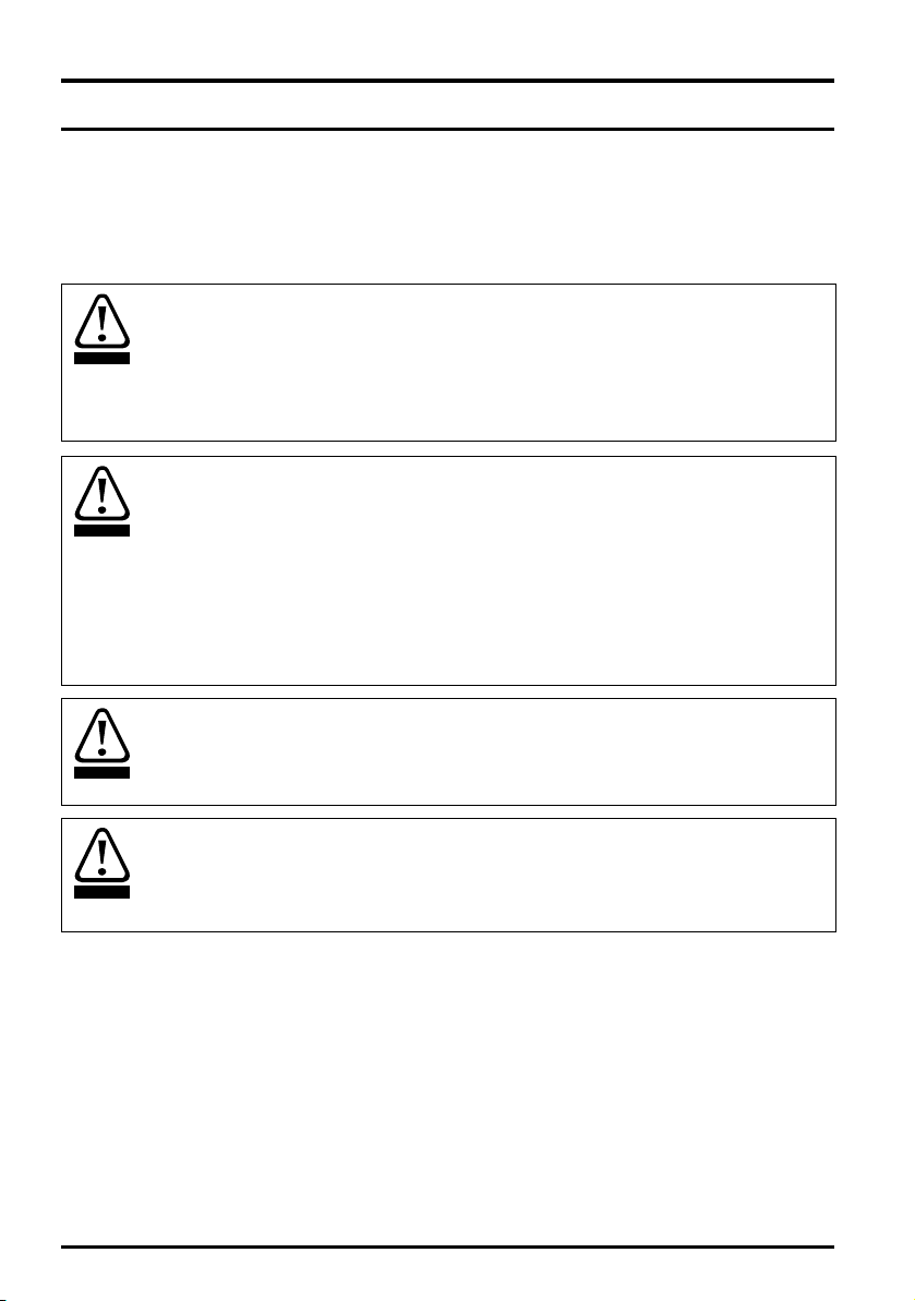
1 Safety information
WARNING
CAUTION
NOTE
1.1 Warnings, Cautions and Notes
A Warning contains information which is essential for avoiding a safety hazard.
A Caution contains information which is necessary for avoiding a risk of damage to the
product or other equipment.
A Note contains information, which helps to ensure correct operation of the product.
1.2 Electrical safety - general warning
The voltages used in the drive can cause severe electrical shock and/or burns, and could be lethal.
Extreme care is necessary at all times when working with or adjacent to the drive. Specific warnings
are given at the relevant places in this guide.
1.3 System design and safety of personnel
The drive is intended as a component for professional incorporation into complete equipment or a
system. If installed incorrectly, the drive may present a safety hazard.
The drive uses high voltages and currents, carries a high level of stored electrical energy, and is used
to control equipment which can cause injury.
Close attention is required to the electrical installation and the system design to avoid hazards either
in normal operation or in the event of equipment malfunction. System design, installation,
commissioning/start-up and maintenance must be carried out by personnel who have the necessary
training and experience. They must read this safety information and this Guide carefully.
The STOP and Safe Torque Off functions of the drive do not isolate dangerous voltages from the
output of the drive or from any external option unit. The supply must be disconnected by an approved
electrical isolation device before gaining access to the electrical connections.
With the sole exception of the Safe Torque Off function, none of the drive functions must be
used to ensure safety of personnel, i.e. they must not be used for safety-related functions.
Careful consideration must be given to the functions of the drive which might result in a hazard,
either through their intended behavior or through incorrect operation due to a fault. In any application
where a malfunction of the drive or its control system could lead to or allow damage, loss or injury, a
risk analysis must be carried out, and where necessary, further measures taken to reduce the risk for example, an over-speed protection device in case of failure of the speed control, or a fail-safe
mechanical brake in case of loss of motor braking.
The Safe Torque Off function may be used in a safety-related application. The system designer is
responsible for ensuring that the complete system is safe and designed correctly according to the
relevant safety standards.
Safety information
Product information Mechanical installation Electrical installation Technical data UL listing information
1.4 Environmental limits
Instructions in this guide regarding transport, storage, installation and use of the drive must be
complied with, including the specified environmental limits. Drives must not be subjected to
excessive physical force.
Unidrive M100 to M400 Frame 1 to 4 Power Installation Guide
Issue Number: 1
7
Page 8

1.5 Access
Drive access must be restricted to authorized personnel only. Safety regulations which apply at the
place of use must be complied with.
1.6 Fire protection
The drive enclosure is not classified as a fire enclosure. A separate fire enclosure must be provided.
For further information, refer to section 3.2.5 Fire protection on page 17.
1.7 Compliance with regulations
The installer is responsible for complying with all relevant regulations, such as national wiring
regulations, accident prevention regulations and electromagnetic compatibility (EMC) regulations.
Particular attention must be given to the cross-sectional areas of conductors, the selection of fuses
or other protection, and protective ground (earth) connections.
This guide contains instruction for achieving compliance with specific EMC standards.
Within the European Union, all machinery in which this product is used must comply with the
following directives:
2006/42/EC: Safety of machinery.
2014/30/EU: Electromagnetic Compatibility Directive.
1.8 Motor
Ensure the motor is installed in accordance with the manufacturer’s recommendations. Ensure the
motor shaft is not exposed.
Standard squirrel cage induction motors are designed for single speed operation. If it is intended to
use the capability of the drive to run a motor at speeds above its designed maximum, it is strongly
recommended that the manufacturer is consulted first.
Low speeds may cause the motor to overheat because the cooling fan becomes less effective. The
motor should be installed with a protection thermistor. If necessary, an electric forced vent fan should
be used.
The values of the motor parameters set in the drive affect the protection of the motor. The default
values in the drive should not be relied upon.
It is essential that the correct value is entered in Pr 00.006 motor rated current. This affects the
thermal protection of the motor.
1.9 Mechanical brake control
The brake control functions are provided to allow well co-ordinated operation of an external brake
with the drive. While both hardware and software are designed to high standards of quality and
robustness, they are not intended for use as safety functions, i.e. where a fault or failure would result
in a risk of injury. In any application where the incorrect operation of the brake release mechanism
could result in injury, independent protection devices of proven integrity must also be incorporated.
1.10 Adjusting parameters
Some parameters have a profound effect on the operation of the drive. They must not be altered
without careful consideration of the impact on the controlled system. Measures must be taken to
prevent unwanted changes due to error or tampering.
8
Unidrive M100 to M400 Frame 1 to 4 Power Installation Guide
Issue Number: 1
Page 9

1.11 Electrical installation
1.11.1 Electric shock risk
The voltages present in the following locations can cause severe electric shock and may be lethal:
• AC supply cables and connections
• Output cables and connections
• Many internal parts of the drive, and external option units
Unless otherwise indicated, control terminals are single insulated and must not be touched.
1.11.2 Stored charge
The drive contains capacitors that remain charged to a potentially lethal voltage after the AC supply
has been disconnected. If the drive has been energized, the AC supply must be isolated at least ten
minutes before work may continue.
1.12 Hazard
1.12.1 Falling hazard
The drive presents a falling or toppling hazard. This can still cause injury to personnel and therefore
should be handled with care.
Maximum weight:
Size 1: 0.75 kg (1.65 Ib)
Size 2: 1.3 kg (3.0 lb)
Size 3: 1.5 kg (3.3 lb)
Size 4: 3.13 kg (6.9 Ib)
Safety information
Product information Mechanical installation Electrical installation Technical data UL listing information
Unidrive M100 to M400 Frame 1 to 4 Power Installation Guide
Issue Number: 1
9
Page 10
2 Product information
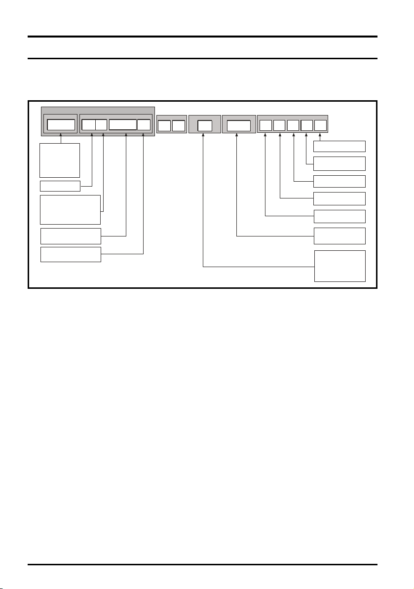
OptionalBuild
IdentificationLabel
Derivative ElectricalSpecifications
M400 - 03 4 00073
ProductLine
UnidriveM400
UnidriveM300
UnidriveM200
UnidriveM201
UnidriveM101
UnidriveM100
FrameSize
:
CustomerCode
01
A B 1 00
CustomerCode:
00 = 50 Hz
01 = 60 Hz
Reserved:
ConformalCoating:
0=Standard
IP / NEMA Rating:
1 = IP20 / NEMA 1
BrakeTransistor:
B = Brake
Cooling:
A = Air
Reserved
01
A
Documentation
1
Documentation:
VoltageRating:
CurrentRating:
HeavyDutycurrentratingx 10
DriveFormat:
A - ACin ACout
2-200V(200-240
-400V(380-480
-575V(500-575
-690V(500-690
± 10%)
4
1-100V(100-120 10%)±
±±10%)
5
6 10%)
± 10%)
0-Suppliedseparately
1-English
2-French
3-Italian
4-German
5-Spanish
2.1 Model number
The way in which the model numbers for the Unidrive M product range is formed is illustrated below:
Figure 2-1 Model number
10
Unidrive M100 to M400 Frame 1 to 4 Power Installation Guide
Issue Number: 1
Page 11
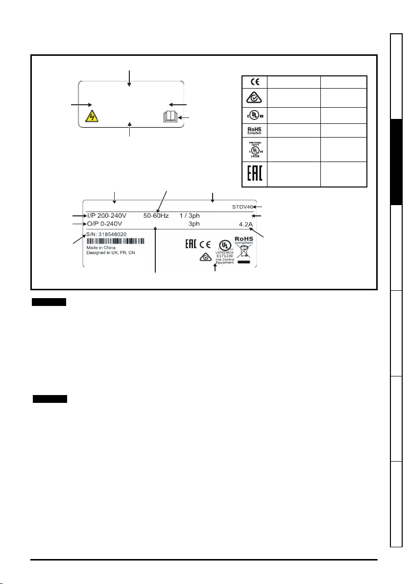
2.2 Nameplate description
Model
number
Input voltage
Output
voltage
Serial
number
Input
frequency
Power
rating
Date code
No. of phases &
Typical input current
Heavy duty
output current
Approvals
M400-022 00042 A
0.75kW
10.4A / 5.4A
Patents: www.ctpatents.info
Manuals: www.ctmanuals.info
0-550Hz
Output
frequency
Key to approvals
Modelnumber
Referto
UserGuide
Datecode
Input
voltage
Powerrating
M400-02200042 A
200-240V0.75kW
V40
CE approval Europe
RCM -Regulatory
Compliance Mark
Australia
UL / cUL approval USA & Canada
RoHS compliant Europe
Functional safety USA & Canada
EurAsian
Conformity
EurAsia
R
NOTE
NOTE
Figure 2-2 Typical drive rating labels
*
Date code format
The date code is split into two sections: a letter followed by a number. The letter indicates
the year, and the number indicates the week number (within the year) in which the drive
was built.The letters go in alphabetical order, starting with A in 1991 (B in 1992, C in 1993
etc).
Example:
A date code of Y28 would correspond to week 28 of year 2015.
2.3 Ratings
The continuous current ratings given are for maximum 40 °C (104 °F), 1000 m altitude and
3 kHz switching frequency. Derating is required for higher switching frequencies, ambient
temperature >40 °C (104 °F) and high altitude. For further information, refer to Chapter
5 Technical data on page 75.
Safety information
Product information
Mechanical installation Electrical installation Technical data UL listing information
Unidrive M100 to M400 Frame 1 to 4 Power Installation Guide
Issue Number: 1
11
Page 12

Table 2-1 100 V drive ratings (100 V to 120 V ±10 %)
Heavy Duty
Model
Input
phases
Maximum
continuous
output current
Open loop
peak current
RFC peak
current
Nominal power
at
100 V
Motor power
ph A A A kW hp
01100017
01100024 2.4 3.6 4.3 0.37 0.5
02100042 4.2 6.3 7.6 0.75 1
1
1.7 2.6 3.1 0.25 0.33
02100056 5.6 8.4 10.1 1.1 1.5
Table 2-2 200 V drive ratings (200 V to 240 V ±10 %)
Heavy Duty
Model
01200017 1 1.7 2.6 3.1 0.25 0.33
01200024 1 2.4 3.6 4.3 0.37 0.5
01200033 1 3.3 5 5.9 0.55 0.75
01200042 1 4.2 6.3 7.6 0.75 1
02200024 1/3 2.4 3.6 4.3 0.37 0.5
02200033 1/3 3.3 5 5.9 0.55 0.75
02200042 1/3 4.2 6.3 7.6 0.75 1
02200056 1/3 5.6 8.4 10.1 1.1 1
02200075 1/3 7.5 11.3 13.5 1.5 2
03200100 1/3 10 15 18 2.2 3
04200133 1/3 13.3 20 23.9 3 3
04200176 3 17.6 26.4 31.7 4 5
Input phases
ph A A A kW hp
Maximum
continuous
output current
Open loop
peak current
RFC peak
current
Nominal power
at 230 V
at 100 V
Motor power
at 230 V
12
Unidrive M100 to M400 Frame 1 to 4 Power Installation Guide
Issue Number: 1
Page 13
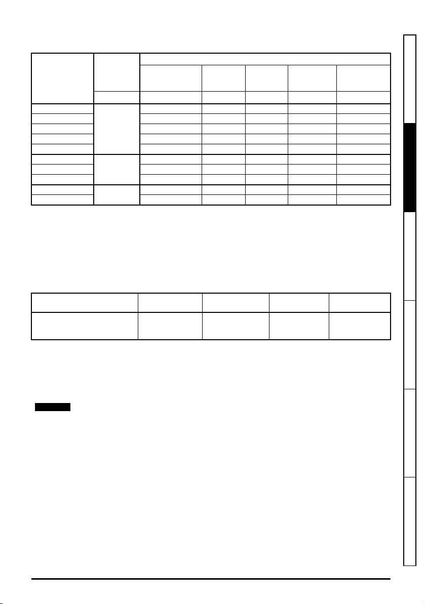
Table 2-3 400 V drive ratings (380 V to 480 V ±10 %)
NOTE
Heavy Duty
Model
02400013
02400018 1.8 2.7 3.2 0.55 0.75
02400023 2.3 3.5 4.1 0.75 1
02400032 3.2 4.8 5.8 1.1 1.5
02400041 4.1 6.2 7.4 1.5 2
03400056
03400073 7.3 11 13.1 3 3
03400094 9.4 14.1 16.9 4 5
04400135
04400170 17 25.5 30.6 7.5 10
Input phases
ph A A A kW hp
3
3
3
Maximum
continuous
output current
1.3 2 2.3 0.37 0.5
5.6 8.4 10.1 2.2 3
13.5 20.3 24.3 5.5 7.5
Open loop
peak current
RFC peak
current
Nominal
power at 400 V
Motor power
at 460 V
2.3.1 Typical short term overload limits
The maximum percentage overload limit changes depending on the selected motor. Variations in
motor rated current, motor power factor and motor leakage inductance all result in changes in the
maximum possible overload. The exact value for a specific motor can be calculated using the
equations detailed in Menu 4 in the Parameter Reference Guide.
Typical values are shown in the table below for RFC-A and open loop (OL) modes:
Table 2-4 Typical overload limits
Operating mode RFC From cold RFC From 100 %
Heavy Duty overload with motor
rated current = drive rated
180 % for 3 s 180 % for 3 s 150 % for 60 s 150 % for 8 s
current
Open loop from
cold
Open loop from
100 %
Safety information
Product information
Mechanical installation Electrical installation Technical data UL listing information
Generally the drive rated current is higher than the matching motor rated current allowing a higher
level of overload than the default setting.
The time allowed in the overload region is proportionally reduced at very low output frequency on
some drive ratings.
The maximum overload level which can be attained is independent of the speed.
Unidrive M100 to M400 Frame 1 to 4 Power Installation Guide
Issue Number: 1
13
Page 14
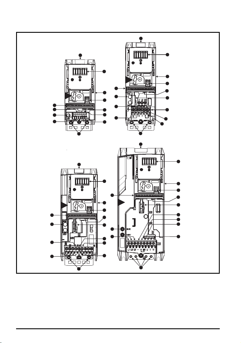
2.4 Drive features
10
5
8
7
7
11
6
4
1
9
9
4
1
3
6
8
2
2
2
2
4
4
1
10
8
6
6
3
3
5
7
11
1
8
11
9
5
11
10
12
12
12
12
10
5
7
14
14
13
13
14
13
14
13
3
4
2
1
Figure 2-3 Features of the drive (Unidrive M400 illustrated)
Key
1. Rating label (On side of
drive)
2. Identification label 6. Braking terminal 10. Motor connections 14. Keypad connection
3. Option module
connection
4. Relay connections 8. DC bus + 12. Ground connections
5. Control connections 9. DC bus - 13. Safe Torque Off
7. Internal EMC filter
screw
11. AC supply connections
connections
14
Unidrive M100 to M400 Frame 1 to 4 Power Installation Guide
Issue Number: 1
Page 15
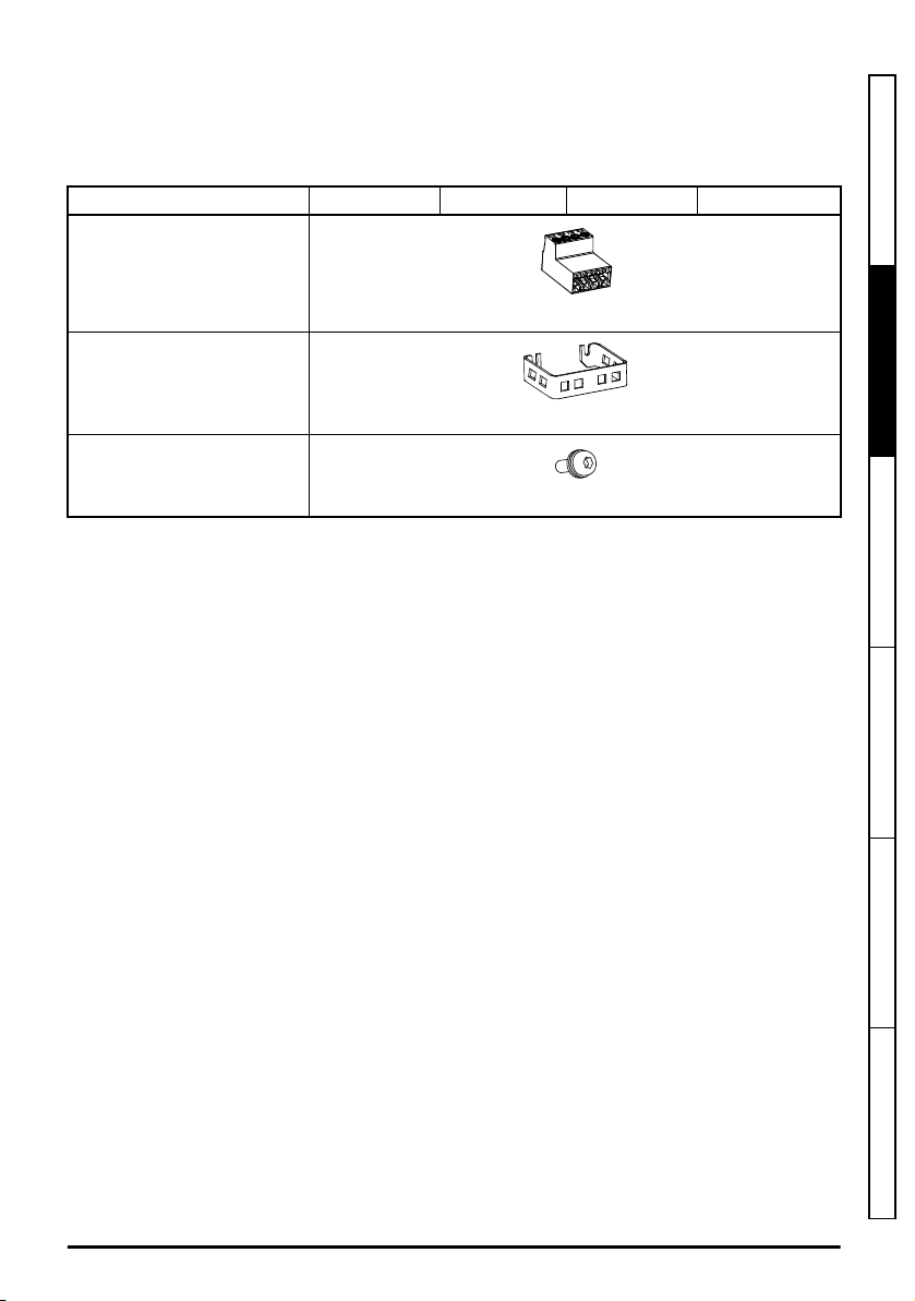
2.5 Items supplied with the drive
The drive is supplied with a copy of the Control Quick Start Guide, a copy of the Power Installation
Guide, a safety information booklet, the Certificate of Quality and the items shown in Table 2-5.
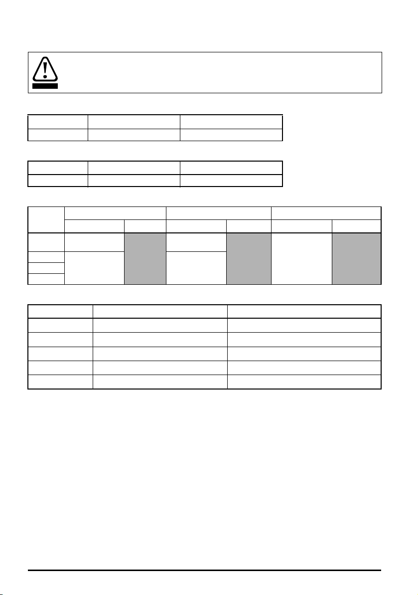
Table 2-5 Parts supplied with the drive
Description Size 1 Size 2 Size 3 Size 4
Safety information
STO connector
Grounding bracket
M4 x 8 Double Sem Torx screw
* Unidrive M300/ M400 only.
*
Product information
x 1
x 1
Mechanical installation Electrical installation Technical data UL listing information
x 4
Unidrive M100 to M400 Frame 1 to 4 Power Installation Guide
Issue Number: 1
15
Page 16
3 Mechanical installation
WARNING
WARNING
WARNING
WARNING
3.1 Safety information
This chapter describes how to use all mechanical details to install the drive. The drive is intended to
be installed in an enclosure. Key features of this chapter include:
• High IP as standard
• Enclosure sizing and layout
• Terminal location and torque settings
Follow the instructions
The mechanical and electrical installation instructions must be adhered to. Any questions
or doubt should be referred to the supplier of the equipment. It is the responsibility of the
owner or user to ensure that the installation of the drive and any external option unit, and
the way in which they are operated and maintained, comply with the requirements of the
Health and Safety at Work Act in the United Kingdom or applicable legislation and
regulations and codes of practice in the country in which the equipment is used.
Stored charge
The drive contains capacitors that remain charged to a potentially lethal voltage after the
AC supply has been disconnected. If the drive has been energized, the AC supply must
be isolated at least ten minutes before work may continue.
Normally, the capacitors are discharged by an internal resistor. Under certain, unusual
fault conditions, it is possible that the capacitors may fail to discharge, or be prevented
from being discharged by a voltage applied to the output terminals. If the drive has failed
in a manner that causes the display to go blank immediately, it is possible the capacitors
will not be discharged. In this case, consult Emerson Industrial Automation or their
authorized distributor.
Competence of the installer
The drive must be installed by professional assemblers who are familiar with the
requirements for safety and EMC. The assembler is responsible for ensuring that the end
product or system complies with all the relevant laws in the country where it is to be used.
Enclosure
The drive is intended to be mounted in an enclosure which prevents access except by
trained and authorized personnel, and which prevents the ingress of contamination. It is
designed for use in an environment classified as pollution degree 2 in accordance with IEC
60664-1. This means that only dry, non-conducting contamination is acceptable.
3.2 Planning the installation
The following considerations must be made when planning the installation:
3.2.1 Access
Access must be restricted to authorized personnel only. Safety regulations which apply at the place
of use must be complied with.
The IP (Ingress Protection) rating of the drive is installation dependent.
16
Unidrive M100 to M400 Frame 1 to 4 Power Installation Guide
Issue Number: 1
Page 17
3.2.2 Environmental protection
NOTE
The drive must be protected from:
• Moisture, including dripping water or spraying water and condensation. An anti-condensation
heater may be required, which must be switched off when the drive is running.
• Contamination with electrically conductive material
• Contamination with any form of dust which may restrict the fan, or impair airflow over various
components
• Temperature beyond the specified operating and storage ranges
• Corrosive gasses
During installation it is recommended that the vents on the drive are covered to prevent
debris (e.g. wire off-cuts) from entering the drive.
3.2.3 Cooling
The heat produced by the drive must be removed without its specified operating temperature being
exceeded. Note that a sealed enclosure gives much reduced cooling compared with a ventilated one,
and may need to be larger and/or use internal air circulating fans.
For further information, refer to section 3.5.1
Enclosure sizing
on page 24.
3.2.4 Electrical safety
The installation must be safe under normal and fault conditions. Electrical installation instructions are
given in Chapter 4
Electrical installation on page 37
.
3.2.5 Fire protection
The drive enclosure is not classified as a fire enclosure. A separate fire enclosure must be provided.
For installation in the USA, a NEMA 12 enclosure is suitable.
For installation outside the USA, the following (based on IEC 62109-1, standard for PV inverters) is
recommended.
Enclosure can be metal and/or polymeric, polymer must meet requirements which can be
summarized for larger enclosures as using materials meeting at least UL 94 class 5VB at the point of
minimum thickness.
Air filter assemblies to be at least class V-2.
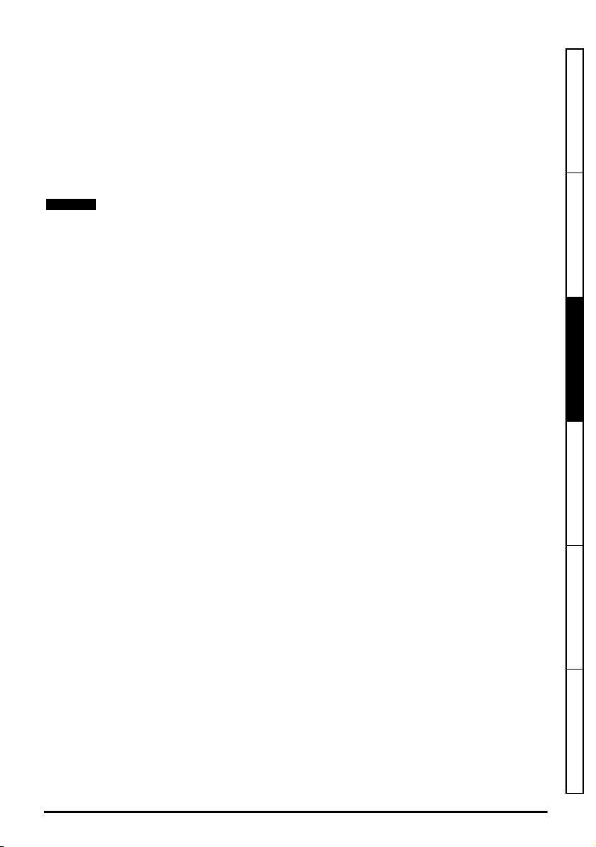
The location and size of the bottom shall cover the area shown in Figure 3-1. Any part of the side
which is within the area traced out by the 5° angle is also considered to be part of the bottom of the
fire enclosure.
Safety information Product information
Mechanical installation
Electrical installation Technical data UL listing information
Unidrive M100 to M400 Frame 1 to 4 Power Installation Guide
Issue Number: 1
17
Page 18
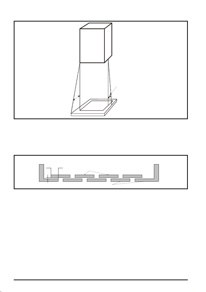
Figure 3-1 Fire enclosure bottom layout
Drive
5
o
5
o
N o t le s s
t ha n 2 X
B a ff le p la te s ( m a y b e
a b ov e o r b e lo w b o tt o m
o f e n cl o su r e)
X
B o tt o m o f f ir e
e n cl os u re
Not less
than 2
times ‘X’
Baffle plates (may be above or
below bottom of enclosure)
Bottom of fire enclosure
X
The bottom, including the part of the side considered to be part of the bottom, must be designed to
prevent escape of burning material - either by having no openings or by having a baffle construction.
This means that openings for cables etc. must be sealed with materials meeting the 5VB
requirement, or else have a baffle above. See Figure 3-2 for acceptable baffle construction. This
does not apply for mounting in an enclosed electrical operating area (restricted access) with concrete
floor.
Figure 3-2 Fire enclosure baffle construction
3.2.6 Electromagnetic compatibility
Variable speed drives are powerful electronic circuits which can cause electromagnetic interference if
not installed correctly with careful attention to the layout of the wiring.
Some simple routine precautions can prevent disturbance to typical industrial control equipment.
If it is necessary to meet strict emission limits, or if it is known that electromagnetically sensitive
equipment is located nearby, then full precautions must be observed. In-built into the drive, is an
internal EMC filter, which reduces emissions under certain conditions. If these conditions are
exceeded, then the use of an external EMC filter may be required at the drive inputs, which must be
located very close to the drives. Space must be made available for the filters and allowance made for
carefully segregated wiring. Both levels of precautions are covered in section 4.7
(Electromagnetic compatibility) on page 61
.
EMC
3.2.7 Hazardous areas
The drive must not be located in a classified hazardous area unless it is installed in an approved
enclosure and the installation is certified.
18
Unidrive M100 to M400 Frame 1 to 4 Power Installation Guide
Issue Number: 1
Page 19
3.3 Terminal cover removal
WARNING
WARNING
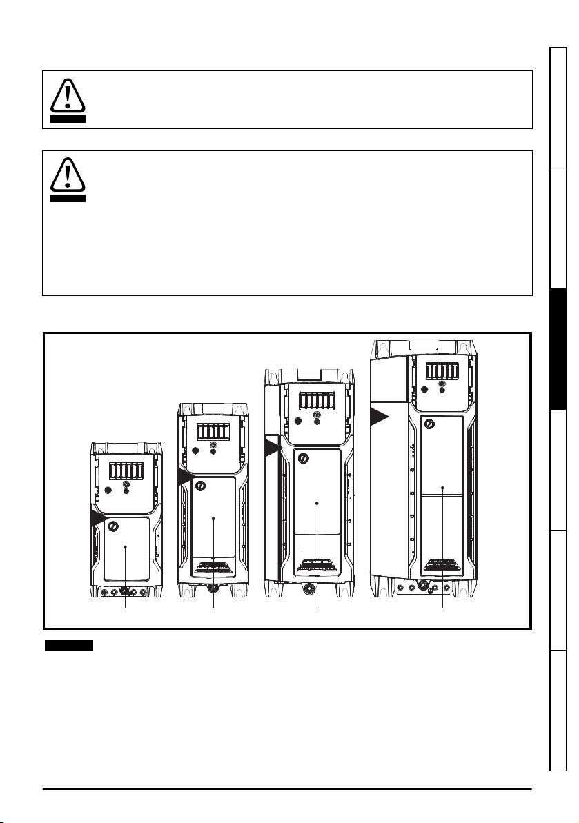
1
2
3
4
Control/ AC/
Motorterminalcover
Control/ AC/
Motorterminalcover
Control/ AC/
Motorterminalcover
Control/ AC/
Motorterminalcover
NOTE
Isolation device
The AC and / or DC power supply must be disconnected from the drive using an approved
isolation device before any cover is removed from the drive or before any servicing work
is performed.
Stored charge
The drive contains capacitors that remain charged to a potentially lethal voltage after the
AC and / or DC power supply has been disconnected. If the drive has been energized,
the power supply must be isolated at least ten minutes before work may continue.
Normally, the capacitors are discharged by an internal resistor. Under certain, unusual
fault conditions, it is possible that the capacitors may fail to discharge, or be prevented
from being discharged by a voltage applied to the output terminals. If the drive has failed
in a manner that causes the display to go blank immediately, it is possible the capacitors
will not be discharged. In this case, consult Emerson Industrial Automation or their
authorized distributor.
3.3.1 Removing the terminal covers
Figure 3-3 Location and identification of terminal covers (Unidrive M400 size 1 to 4 shown)
Safety information Product information
Mechanical installation
Electrical installation Technical data UL listing information
The drives shown in Figure 3-3 above, have a single removable terminal cover which
provides access to all electrical connections, i.e. Control, AC, Motor and Brake functions.
Figure 3-4 illustrates the three steps required to remove the drive terminal covers.
Unidrive M100 to M400 Frame 1 to 4 Power Installation Guide
Issue Number: 1
19
Page 20
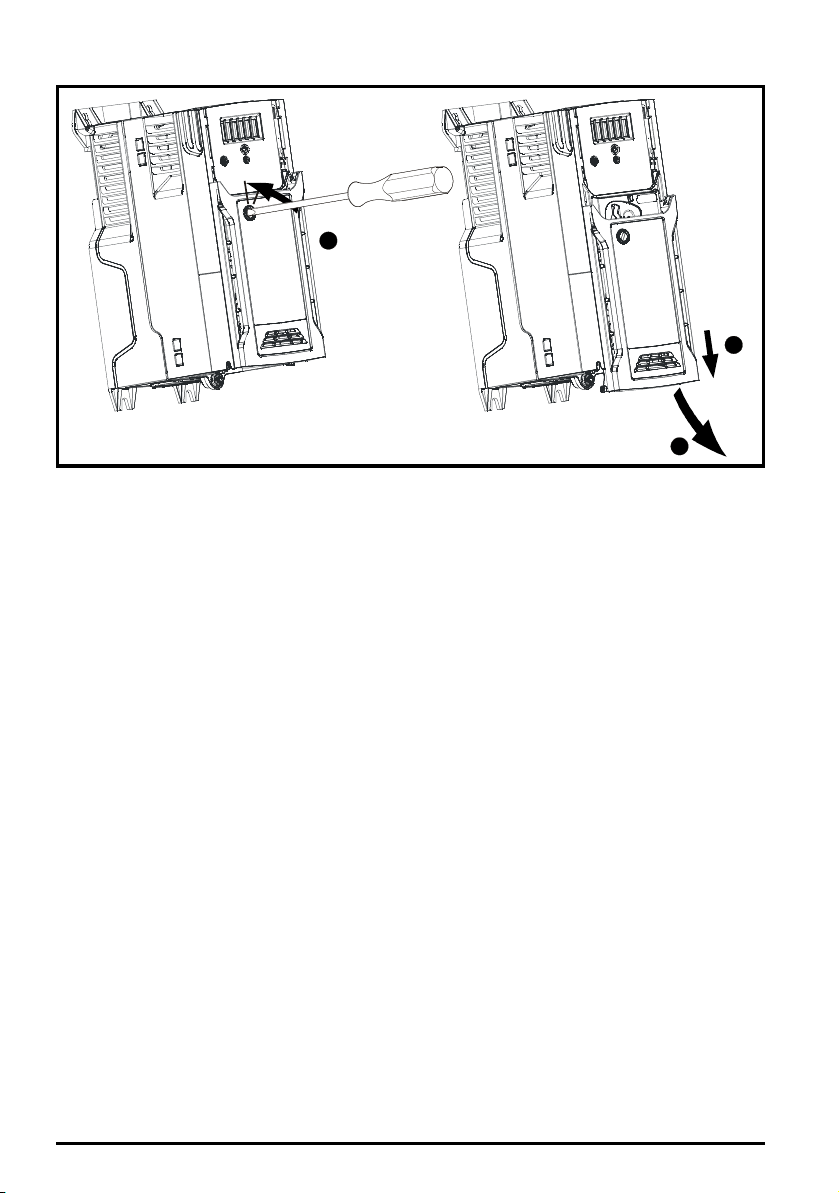
Figure 3-4 Removing the terminal cover (Unidrive M400 size 1 to 4 shown)
1
2
3
1. Using a flat bladed screwdriver, turn the terminal cover locking clip anti-clockwise by
approximately 30°
2. Slide the terminal cover down
3. Remove terminal cover in direction shown.
20
Unidrive M100 to M400 Frame 1 to 4 Power Installation Guide
Issue Number: 1
Page 21
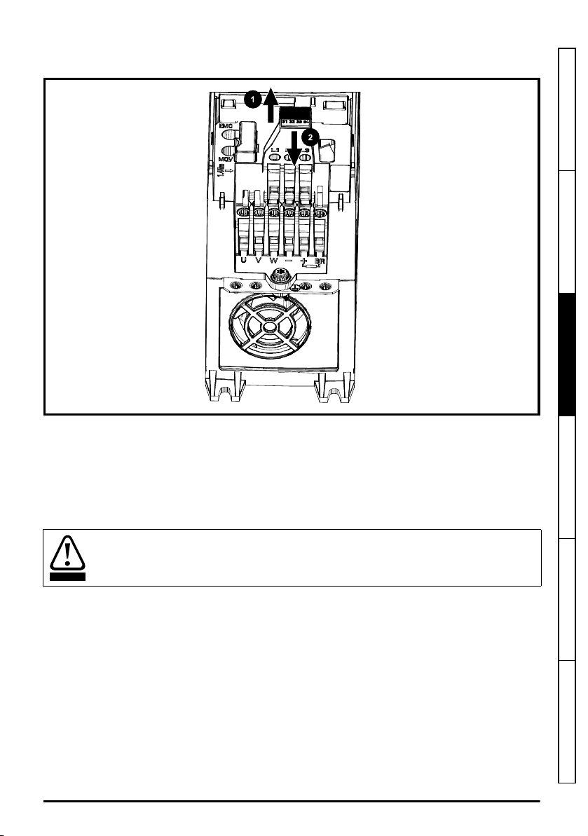
3.3.2 Removal of the STO (Safe Torque Off) connector
WARNING
Figure 3-5 Removing the STO connector
Safety information Product information
Mechanical installation
To remove the STO terminal block:
1. Using tab on STO terminal block, pull upwards.
2. Pull away from the control module as shown on the tab as shown in Figure 3-5 above.
3.4 Drive dimensions and mounting methods
The following drawings show the dimensions of the drive and mounting holes to allow a back-plate to
be prepared.
If the drive has been used at high load levels for a period of time, the heatsink can reach
temperatures in excess of 70 °C (158 °F). Human contact with the heatsink should be
prevented.
The drives can be panel mounted with 0 mm space between the drives.
Unidrive M100 to M400 Frame 1 to 4 Power Installation Guide
Issue Number: 1
Electrical installation Technical data UL listing information
21
Page 22
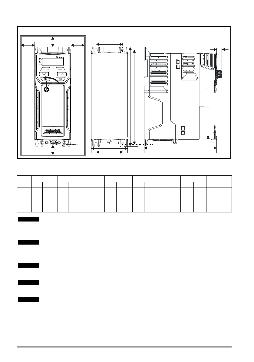
Figure 3-6 Dimensions (Unidrive M200 / M201 shown)
A
W
M2
B
D
B
A
H M1
11 mm
(0.43 in)
Cover
release
NOTE
NOTE
NOTE
NOTE
NOTE
To remove the terminal cover, use a flat bladed screwdriver to rotate the terminal cover locating clip
by approximately 30° in a counter clockwise direction, and then slide the cover down.
Drive
Size
1 160 6.30 75 2.95 130 5.12 143 5.70 53 2.08 5 0.2
2 205 8.07 78 3.07 150 5.91 194 7.63 55 2.17 5 0.2
3 226 8.90 90 3.54 160 6.30 215 8.46 70.7 2.80 5 0.2
4 277 10.91 115 4.53 175 6.89 265 10.43 86 3.40 6 0.23
H W D M1 M2 ∅∅∅∅ A B*
mm in mm in mm in mm in mm in mm in mm in mm in
0 0.00 100 3.93
A minimum clearance of 100 mm above and below Frame 01 to 04 products is required
for applications where the product is subjected to rated load and rated ambient
temperature.
* A minimum clearance of 50 mm above and below Frame 01 to 04 products is permissible
in applications where either the ambient operating temperature is 35 °C or less or the
average output current is derated by 20 %.
Derating for reduced clearances is to be applied in addition to the derating for increased
switching frequency if operating above 3 kHz.
We recommend that cables are routed carefully to ensure that the airflow in and out of the
product is not impeded, when using the reduced clearances.
If DIN rail mounting is used in an installation where the drive is to be subjected to shock
or vibration, it is recommended that the bottom mounting screws are used to secure the
drive to the back-plate. If the installation is going to be subjected to heavy shock or
vibration, then it is recommended that the drive is surface mounted rather than DIN rail
mounted.
22
Unidrive M100 to M400 Frame 1 to 4 Power Installation Guide
Issue Number: 1
Page 23
The DIN rail mounting mechanism has been designed so no tools are required to install
NOTE
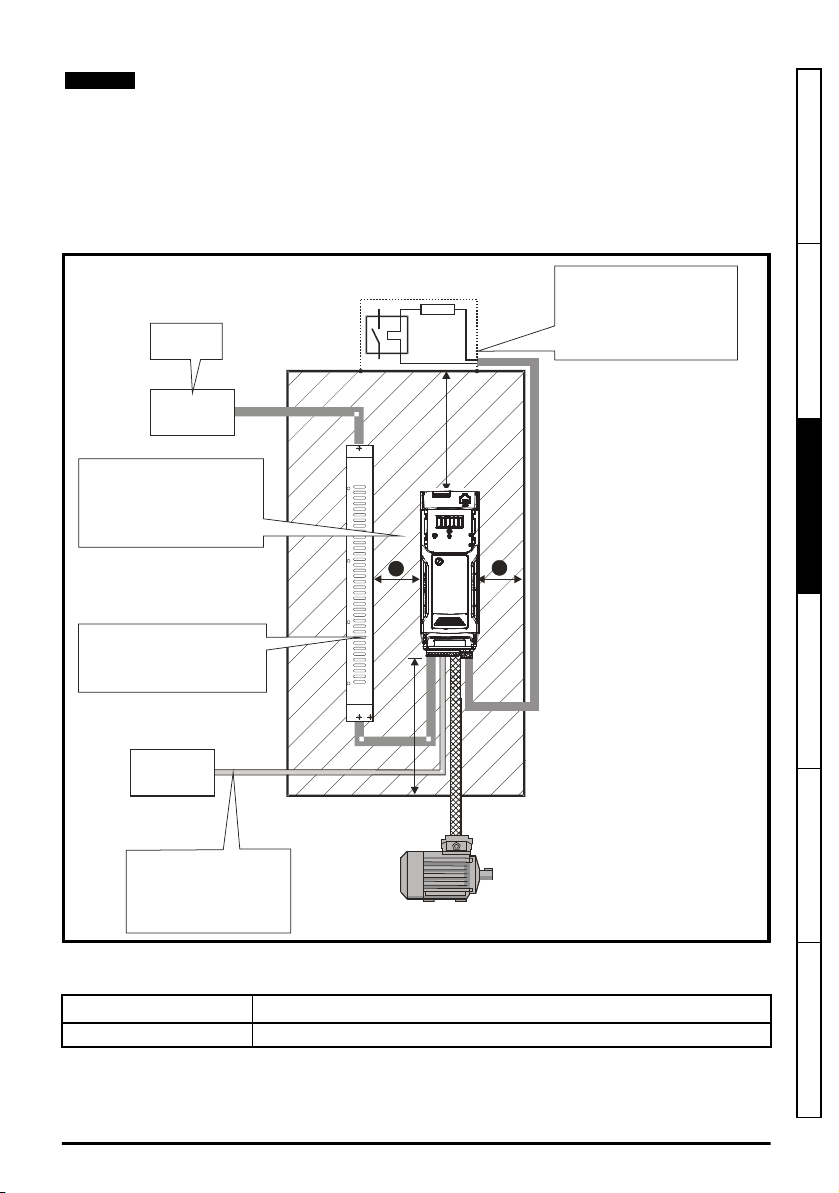
³100mm
(4in)
Enclosure
ACsupply
contactorand
fusesorMCB
Locateas
required
Locateas
required
External
controller
Signalcables
Planforallsignalcables
toberoutedatleast
300mm(12in)fromthe
driveandanypowercable
Ensureminimumclearances
aremaintainedforthedrive
andexternalEMCfilter.Forced
orconvectionair-flowmustnot
berestrictedbyanyobjector
cabling
³100mm
(4in)
Optionalbrakingresistorandoverload
Locateoptionalbraking
resistorexternalto
cubicle(preferablyneartoor
ontopofthecubicle).
Locatetheoverloadprotection
deviceasrequired
TheexternalEMCfiltercanbe
bookcasemounted(nexttothe
drive)orfootprintmounted(with
thedrivemountedontothefilter).
Note
ForEMCcompliance:
1)WhenusinganexternalEMC
filter,onefilterisrequiredfor
eachdrive
2)Powercablingmustbeat
least100mm(4in)fromthe
driveinalldirections
B
B
B
and remove the drive from a DIN rail. Please ensure the top mounting lugs are located
correctly on the DIN rail before installation is initiated. The DIN rail used should conform
to DIN46277-3.
3.5 Enclosure layout
Please observe the clearances in the diagram below taking into account any appropriate notes for
other devices / auxiliary equipment when planning the installation.
Figure 3-7 Enclosure layout (Unidrive M400 illustrated)
Safety information Product information
Mechanical installation
Table 3-1 Spacing required between drive / enclosure and drive / EMC filter
Drive size Spacing (B)
All 0 mm (0.00 in)
Electrical installation Technical data UL listing information
Unidrive M100 to M400 Frame 1 to 4 Power Installation Guide
Issue Number: 1
23
Page 24

3.5.1 Enclosure sizing
A
e
P
k T
in tTex t
–( )
-----------------------------------
=
NOTE
1. Add the dissipation figures from section 5.1.2
to be installed in the enclosure.
2. If an external EMC filter is to be used with each drive, add the dissipation figures from section
5.2.1
EMC filter ratings
on page 97 for each external EMC filter that is to be installed in the
enclosure.
3. If the braking resistor is to be mounted inside the enclosure, add the average power figures for
each braking resistor that is to be installed in the enclosure.
4. Calculate the total heat dissipation (in Watts) of any other equipment to be installed in the
enclosure.
5. Add the heat dissipation figures obtained above. This gives a figure in Watts for the total heat that
will be dissipated inside the enclosure.
Calculating the size of a sealed enclosure
The enclosure transfers internally generated heat into the surrounding air by natural convection (or
external forced air flow); the greater the surface area of the enclosure walls, the better is the
dissipation capability. Only the surfaces of the enclosure that are unobstructed (not in contact with a
wall or floor) can dissipate heat.
Calculate the minimum required unobstructed surface area
Where:
A
Unobstructed surface area in m2 (1 m2 = 10.9 ft2)
e
T
Maximum expected temperature in
ext
T
Maximum permissible temperature in oC
int
P
Power in Watts dissipated by
k
Heat transmission coefficient of the enclosure material in W/m2/oC
Example
To calculate the size of an enclosure for the following:
• Two drives operating at the Normal Duty rating
• External EMC filter for each drive
• Braking resistors are to be mounted outside the enclosure
• Maximum ambient temperature inside the enclosure: 40 °C
• Maximum ambient temperature outside the enclosure: 30 °C
For example, if the power dissipation from each drive is 187 W and the power dissipation from each
external EMC filter is 9.2 W.
Total dissipation: 2 x (187 + 9.2) =392.4 W
Power dissipation
Ae for the enclosure from:
o
C
outside
all
heat sources in the enclosure
the enclosure
inside
the enclosure
on page 77 for each drive that is
Power dissipation for the drives and the external EMC filters can be obtained from Chapter
5
Technical data
on page 75.
The enclosure is to be made from painted 2 mm (0.079 in) sheet steel having a heat transmission
coefficient of 5.5 W/m2/oC. Only the top, front, and two sides of the enclosure are free to dissipate
heat.
The value of 5.5 W/m2/ºC can generally be used with a sheet steel enclosure (exact values can be
obtained from the supplier of the material). If in any doubt, allow for a greater margin in the
temperature rise.
24
Unidrive M100 to M400 Frame 1 to 4 Power Installation Guide
Issue Number: 1
Page 25
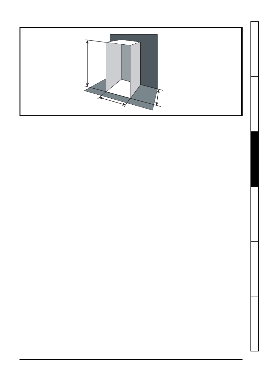
Figure 3-8 Enclosure having front, sides and top panels free to dissipate heat
W
H
D
A
e
392.4
5.5 40 30–( )
---------------------------------
=
W
Ae2H D–
H D+
--------------------------
=
W
7.135 2 2× 0.6×( )–
2 0.6+
-----------------------------------------------------
=
Insert the following values:
T
40 °C
int
T
30 °C
ext
k
5.5
P
392.4 W
The minimum required heat conducting area is then:
Safety information Product information
Mechanical installation
= 7.135 m2 (77.8 ft2)
(1 m2 = 10.9 ft2)
Estimate two of the enclosure dimensions - the height (H) and depth (D), for instance. Calculate the
width (W) from:
Inserting H = 2m and D = 0.6 m, obtain the minimum width:
=1.821 m (71.7 in)
If the enclosure is too large for the space available, it can be made smaller only by attending to one
or all of the following:
• Using a lower PWM switching frequency to reduce the dissipation in the drives
• Reducing the ambient temperature outside the enclosure, and/or applying forced-air cooling to
the outside of the enclosure
• Reducing the number of drives in the enclosure
• Removing other heat-generating equipment
Unidrive M100 to M400 Frame 1 to 4 Power Installation Guide
Issue Number: 1
Electrical installation Technical data UL listing information
25
Page 26

Calculating the air-flow in a ventilated enclosure
V
3k P
T
in tTex t
–
---------------------------
=
P
o
P
l
-------
V
3 1.3× 323.7×
40 30–
---------------------------------------
=
The dimensions of the enclosure are required only for accommodating the equipment. The
equipment is cooled by the forced air flow.
Calculate the minimum required volume of ventilating air from:
Where:
V
Air-flow in m3 per hour (1 m3/hr = 0.59 ft3/min)
T
Maximum expected temperature in °C outside
ext
T
Maximum permissible temperature in °C
int
P
Power in Watts dissipated by
k
Ratio of
all
heat sources in the enclosure
the enclosure
inside
the enclosure
Where:
P0 is the air pressure at sea level
PI is the air pressure at the installation
Typically use a factor of 1.2 to 1.3, to allow also for pressure-drops in dirty air-filters.
Example
To calculate the size of an enclosure for the following:
• Three drives operating at the Normal Duty rating
• External EMC filter for each drive
• Braking resistors are to be mounted outside the enclosure
• Maximum ambient temperature inside the enclosure: 40 °C
• Maximum ambient temperature outside the enclosure: 30 °C
For example, dissipation of each drive: 101 W and dissipation of each external EMC filter: 6.9 W
(max).
Total dissipation: 3 x (101 + 6.9) = 323.7 W
Insert the following values:
T
40 °C
int
T
30 °C
ext
k
1.3
P
323.7 W
Then:
=
126.2 m3/hr (74.5 ft3 /min)
26
Unidrive M100 to M400 Frame 1 to 4 Power Installation Guide
(1 m3/ hr = 0.59 ft3/min)
Issue Number: 1
Page 27
3.5.2 Enclosure design and drive ambient temperature
Drive derating is required for operation in high ambient temperatures
Totally enclosing or through panel mounting the drive in either a sealed cabinet (no airflow) or in a
well ventilated cabinet makes a significant difference on drive cooling.
The chosen method affects the ambient temperature value (T
) which should be used for any
rate
necessary derating to ensure sufficient cooling for the whole of the drive.
The ambient temperature for the four different combinations is defined below:
1. Totally enclosed with no air flow (<2 m/s) over the drive T
2. Totally enclosed with air flow (>2 m/s) over the drive T
3. Through panel mounted with no airflow (<2 m/s) over the drive T
T
int
4. Through panel mounted with air flow (>2 m/s) over the drive T
rate
rate
= T
= T
int
rate
rate
+ 5 °C
int
= the greater of T
= the greater of T
+5 °C, or
ext
or T
ext
int
Where:
T
= Temperature outside the cabinet
ext
T
= Temperature inside the cabinet
int
T
= Temperature used to select current rating from tables in Chapter 5
rate
Technical data
on
page 75.
3.6 Heatsink fan operation
The drive is ventilated by an internal heatsink fan. The fan channels air through the heatsink
chamber.
Ensure the minimum clearances around the drive are maintained to allow air to flow freely.
The heatsink fan on all drive sizes is a variable speed fan (except for size 1 which has a single speed
fan). The drive controls the speed at which the fan runs based on the temperature of the heatsink
and the drive's thermal model system. The maximum speed at which the fan operates can be limited
in Pr
06.045
. This could incur an output current derating.
Table 3-2 Environmental considerations
Environment Comments
Clean
Dry, dusty (non-conductive)
Dry, dusty (conductive)
Regular cleaning recommended
Safety information Product information
Mechanical installation
Electrical installation Technical data UL listing information
Unidrive M100 to M400 Frame 1 to 4 Power Installation Guide
Issue Number: 1
27
Page 28

3.7 External EMC filter
The external EMC filter details for each drive rating are provided in the table below.
Model CT part number
100 V
01100017 to 01100024
02100042 to 02100056 4200-2000 0.90 1.98
200 V
01200017 to 01200042
02200024 to 02200075
03200100
04200133 to 04200176
400 V
02400013 to 02400041
03400056 to 03400094
04400135 to 04400170
Mount the external EMC filter following the guidelines in section 4.7.5
emission standards
on page 69
4200-1000
4200-1001 (low leakage)
4200-1000
4200-1001 (low leakage)
4200-2001
4200-2002 (low leakage)
4200-2003
4200-2004 (low leakage)
4200-3000
4200-3001 (low leakage)
4200-3004
4200-3005 (low leakage)
4200-4000
4200-4001 (low leakage)
4200-4002
4200-4003 (low leakage)
4200-2005
4200-2006 (low leakage)
4200-3008
4200-3009 (low leakage)
4200-4004
4200-4005 (low leakage)
Compliance with generic
Weight
kg lb
0.49 1.08
0.49 1.08
0.86 1.89
0.88 1.94
0.92 2.02
0.95 2.09
1.3 2.86
1.4 3.08
0.82 1.80
1 2.20
1.4 3.08
28
Unidrive M100 to M400 Frame 1 to 4 Power Installation Guide
Issue Number: 1
Page 29
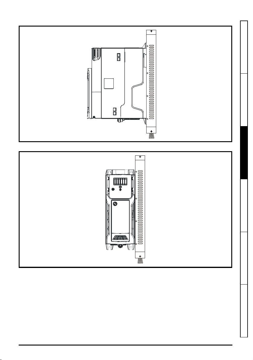
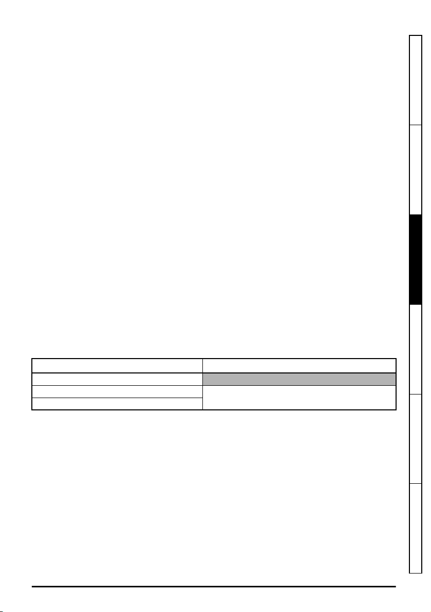
Figure 3-9 Footprint mounting the EMC filter
Figure 3-10 Bookcase mounting the EMC filter
Safety information Product information
Mechanical installation
Electrical installation Technical data UL listing information
Unidrive M100 to M400 Frame 1 to 4 Power Installation Guide
Issue Number: 1
29
Page 30
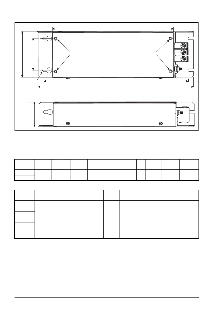
Figure 3-11 Size 1 to 4 external EMC filter
W
C
A
X
X
Y
Y
V
B
H
Y
Y
D
Z
Z
V: Ground stud
Z: Bookcase mounting slot diameter CS: Cable size
Table 3-3 Size 1 external EMC filter dimensions
CT part
number
4200-1000
4200-1001
A B C D H W V/X Y Z CS
160 mm
(6.30 in)
198.8 mm
(7.83 in)
52.4 mm
(2.06 in)
Table 3-4 Size 2 external EMC filter dimensions
CT part
number
4200-2000
4200-2001
4200-2002
4200-2003
4200-2004
4200-2005
4200-2006
A B C D H W V/X Y Z CS
206 mm
(8.11 in)
244.8 mm
(9.64 in)
53.4 mm
(2.10 in)
X: Threaded holes for footprint
mounting of the drive
41 mm
(1.61 in)
41 mm
(1.61 in)
215 mm
(8.46 in)
261 mm
(10.2 in)
75 mm
(2.95 in)
78 mm
(3.07 in)
Y: Footprint mounting hole diameter
4.5 mm
M4
(0.18 in)
4.5 mm
M4
(0.18 in)
4.5 mm
(0.18 in)
4.5 mm
(0.18 in)
1.5 mm
(16 AWG)
4.0 mm
(12 AWG)
1.5 mm
(16 AWG)
2
2
2
30
Unidrive M100 to M400 Frame 1 to 4 Power Installation Guide
Issue Number: 1
Page 31

Table 3-5 Size 3 external EMC filter dimensions
CT part
number
4200-3000
4200-3001
4200-3004
4200-3005
4200-3008
4200-3009
A B C D H W V/X Y Z CS
227 mm
(8.94 in)
265.8 mm
(10.4 in)
59 mm
(2.32 in)
41 mm
(1.61 in)
282 mm
(11.1 in)
Table 3-6 Size 4 external EMC filter dimensions
CT part
number
4200-4000
4200-4001
4200-4002
4200-4003
4200-4004
4200-4005
A B C D H W V/X Y Z CS
279 mm
(10.9 in)
318.8 mm
(12.5 in)
80.5 mm
(3.17 in)
41 mm
(1.61 in)
334 mm
(13.1 in)
90 mm
(3.54 in)
115 mm
(4.53 in)
M4
M5
4.5 mm
(0.18 in)
5.5 mm
(0.22 in)
4.5 mm
(0.18 in)
5.5 mm
(0.22 in)
4.0 mm
(12 AWG)
2.5 mm
(14 AWG)
4.0 mm
(12 AWG)
2.5 mm
(14 AWG)
Safety information Product information
2
2
2
2
Mechanical installation
Electrical installation Technical data UL listing information
Unidrive M100 to M400 Frame 1 to 4 Power Installation Guide
Issue Number: 1
31
Page 32

3.7.1 EMC filter torque settings
Table 3-7 Optional external EMC filter terminal data
CT part
number
4200-1000
4200-1001
4200-2000
4200-2001
4200-2002
4200-2003
4200-2004
4200-2005
4200-2006
4200-3000
4200-3001
4200-3004
4200-3005
4200-3008
4200-3009
4200-4000
4200-4001
4200-4002
4200-4003
4200-4004
4200-4005
*
Flex wire.
Table 3-8 Fastener details for drive footprint mounting on external EMC filter
Type Size 1 Size 2 Size 3 Size 4
Thread size M4 M4 M4 M5
Length (mm) 12 12 12 12
Power connections Ground connections
Max cable
size
*
10 mm
(6 AWG)
6 mm
(8 AWG)
10 mm
(6 AWG)
6 mm
(8 AWG)
6 mm
(8 AWG)
6 mm
(8 AWG)
Max torque Ground stud size Max torque
2
2
2
2
2
2
1.8 N m
(1.4 lb ft)
1.8 N m
(1.4 lb ft)
1.8 N m
(1.4 lb ft)
1.8 N m
(1.4 lb ft)
1.8 N m
(1.4 lb ft)
1.8 N m
(1.4 lb ft)
M4
M4
M4
M4
M4
M5
1.7 N m
(1.3 lb ft)
1.7 N m
(1.3 lb ft)
1.7 N m
(1.3 lb ft)
1.7 N m
(1.3 lb ft)
1.7 N m
(1.3 lb ft)
2.2 N m
(1.6 lb ft)
32
Unidrive M100 to M400 Frame 1 to 4 Power Installation Guide
Issue Number: 1
Page 33
3.8 Electrical terminals
5
4
1
2
3
7
8
2
8
6
3
4
1
5
7
7
4
6
3
5
1
2
8
2
5
7
8
1
4
12
6
4
3
2
1
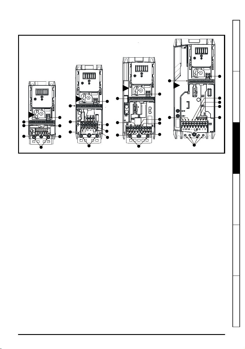
Figure 3-12 Location of the power and ground terminals (Unidrive M400 size 1 to 4 shown)
Key:
1. Control terminals 4. AC power terminals 7. DC bus +
2. Relay terminals 5. Motor terminals 8. Brake terminal
3. Ground connections 6. DC bus -
Safety information Product information
Mechanical installation
Electrical installation Technical data UL listing information
Unidrive M100 to M400 Frame 1 to 4 Power Installation Guide
Issue Number: 1
33
Page 34
3.8.1 Terminal sizes and torque settings
WARNING
To avoid a fire hazard and maintain validity of the UL listing, adhere to the specified
tightening torques for the power and ground terminals. Refer to the following tables.
Table 3-9 Drive control terminal data
Model Connection type Torque setting
All Screw terminals 0.2 N m (0.15 lb ft)
Table 3-10 Drive relay terminal data
Model Connection type Torque setting
All Screw terminals 0.5 N m (0.4 lb ft)
Table 3-11 Drive power terminal data
Model
size
1
2
3
4
Table 3-12 Terminal block maximum cable sizes
Model size Terminal block description Max cable size
AC and motor terminals DC and braking Ground terminal
Recommended Maximum Recommended Maximum Recommended Maximum
0.5 N m
(0.4 lb ft)
1.4 N m
(1 lb ft)
All Control connector
All 2-way relay connector
1 to 4 STO connector
1 AC input / output power connector
2 to 4 AC input / output power connector
0.5 N m
(0.4 lb ft)
1.4 N m
(1 lb ft)
1.5 N m
(1.1 lb ft)
1.5 mm2 (16 AWG)
2.5 mm2 (12 AWG)
0.5 mm2 (20 AWG)
2.5 mm2 (12 AWG)
4.0 mm2 (10 AWG)
34
Unidrive M100 to M400 Frame 1 to 4 Power Installation Guide
Issue Number: 1
Page 35
3.9 Routine maintenance
NOTE
The drive should be installed in a cool, clean, well ventilated location. Contact with moisture and/or
dust with the drive should be avoided.
Regular checks of the following should be carried out to ensure drive / installation reliability are
maximized:
Environment
Ambient temperature
Dust
Moisture Ensure the drive enclosure shows no signs of condensation
Enclosure
Enclosure door filters Ensure filters are not blocked and that air is free to flow
Electrical
Screw connections Ensure all screw terminals remain tight
Crimp terminals
Cables Check all cables for signs of damage
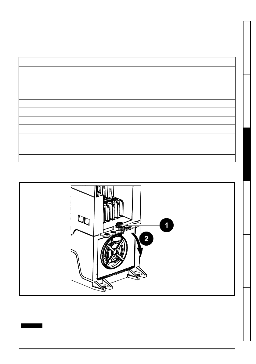
3.9.1 Fan removal procedure
Figure 3-13 Removal of the size 1 to 4 heatsink fan (size 2 illustrated)
Ensure the enclosure temperature remains at or below maximum
specified
Ensure the drive remains dust free – check that the heatsink and drive
fan are not gathering dust. The lifetime of the fan is reduced in dusty
environments.
Ensure all crimp terminals remains tight – check for any discoloration
which could indicate overheating
Safety information Product information
Mechanical installation
Electrical installation Technical data UL listing information
1. Remove the screw from the drive (size 1: Torx 10, size 2 to 4: Torx 20).
2. Tilt the fan guard, then withdraw the fan assembly from the drive housing.
Finally disconnect the fan cable from the drive.
Replace the fan by reversing the above instructions.
Unidrive M100 to M400 Frame 1 to 4 Power Installation Guide
Issue Number: 1
35
Page 36

Table 3-13 Heatsink fan replacement kits
Model Part number
Size 1 3470-0092
Size 2 3470-0095
Size 3 3470-0099
Size 4 3470-0103
36
Unidrive M100 to M400 Frame 1 to 4 Power Installation Guide
Issue Number: 1
Page 37
4 Electrical installation
WARNING
WARNING
WARNING
WARNING
WARNING
WARNING
Many cable management features have been incorporated into the product and accessories, this
chapter shows how to optimize them. Key features include:
• Internal EMC filter
• EMC compliance with shielding / grounding accessories
• Product rating, fusing and cabling information
• Brake resistor details (selection / ratings)
Electric shock risk
The voltages present in the following locations can cause severe electric shock and may be
lethal:
• AC supply cables and connections
• DC and brake cables, and connections
• Output cables and connections
• Many internal parts of the drive, and external option units
Unless otherwise indicated, control terminals are single insulated and must not be touched.
Isolation device
The AC and / or DC power supply must be disconnected from the drive using an approved
isolation device before any cover is removed from the drive or before any servicing work
is performed.
STOP function
The STOP function does not remove dangerous voltages from the drive, the motor or any
external option units.
Safe Torque Off function
The Safe Torque Off function does not remove dangerous voltages from the drive, the
motor or any external option units.
Safety information Product information Mechanical installation
Electrical installation
Stored charge
The drive contains capacitors that remain charged to a potentially lethal voltage after the
AC and / or DC power supply has been disconnected. If the drive has been energized,
the AC and / or DC power supply must be isolated at least ten minutes before work may
continue. Normally, the capacitors are discharged by an internal resistor. Under certain,
unusual fault conditions, it is possible that the capacitors may fail to discharge, or be
prevented from being discharged by a voltage applied to the output terminals. If the drive
has failed in a manner that causes the display to go blank immediately, it is possible the
capacitors will not be discharged. In this case, consult Emerson Industrial Automation or
their authorized distributor.
Equipment supplied by plug and socket
Special attention must be given if the drive is installed in equipment which is connected to
the AC supply by a plug and socket. The AC supply terminals of the drive are connected
to the internal capacitors through rectifier diodes which are not intended to give safety
isolation. If the plug terminals can be touched when the plug is disconnected from the
socket, a means of automatically isolating the plug from the drive must be used (e.g. a
latching relay).
Unidrive M100 to M400 Frame 1 to 4 Power Installation Guide
Issue Number: 1
Technical data UL listing information
37
Page 38
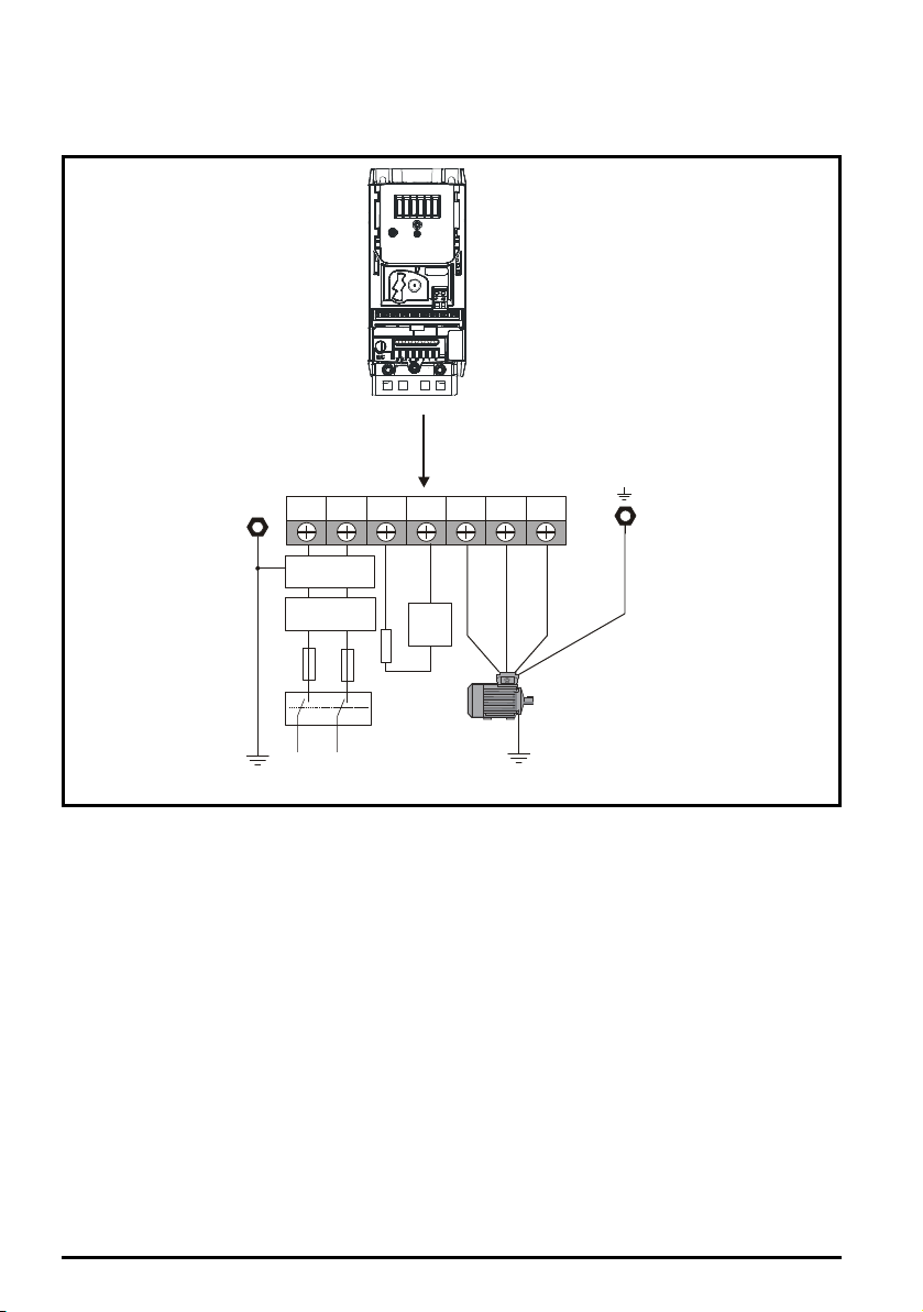
4.1 Power connections
Optional
braking
resistor
L1 L2-N
Optional EMC
filter
Optional
line reactor
Fuses
Mains
Supply
Supply
PE
L2-N
+
BR U
Motor
Optional ground
connection
L1 V W
Thermal
overload
protection
device
4.1.1 AC and DC connections
Figure 4-1 Size 1 power connections (Unidrive M400 shown)
See Figure 4-5
Size 1 to 4 ground connections (Unidrive M400 size 2 shown)
information on ground connections.
38
Unidrive M100 to M400 Frame 1 to 4 Power Installation Guide
on page 42 for further
Issue Number: 1
Page 39
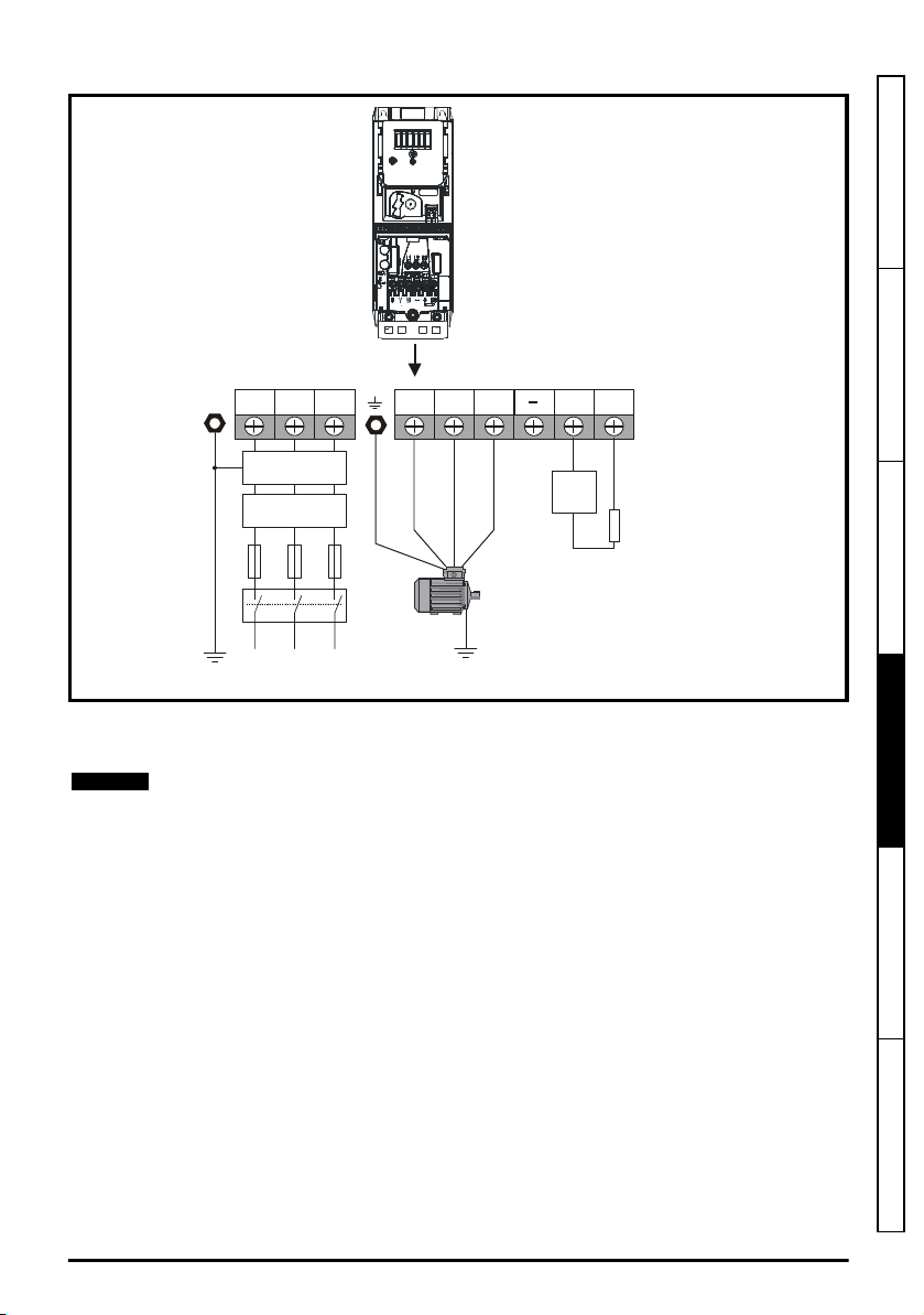
Figure 4-2 Size 2 power connections (Unidrive M400 shown)
L1 L2
L2L1 L3
Optional EMC
Optional
braking
resistor
filter
Optional
line reactor
Fuses
L3
Mains
Supply
Supply
PE U V W
Motor
Optional ground
connection
+ BR
Thermal
overload
protection
device
NOTE
Safety information Product information Mechanical installation
Electrical installation
See Figure 4-5
Size 1 to 4 ground connections (Unidrive M400 size 2 shown)
information on ground connections.
On the size 2 110 V drives or when connecting single phase to a dual rated 200 V unit, the
supply should be connected to L1 and L3. Also the -DC bus (-) terminal on 110 V drives
has no internal connection. The 110 V drives use a voltage doubler circuit on the input,
therefore the default for
Unidrive M100 to M400 Frame 1 to 4 Power Installation Guide
Issue Number: 1
Motor Rated Voltage
(Pr
05.009
on page 42 for further
) is 230 V.
Technical data UL listing information
39
Page 40
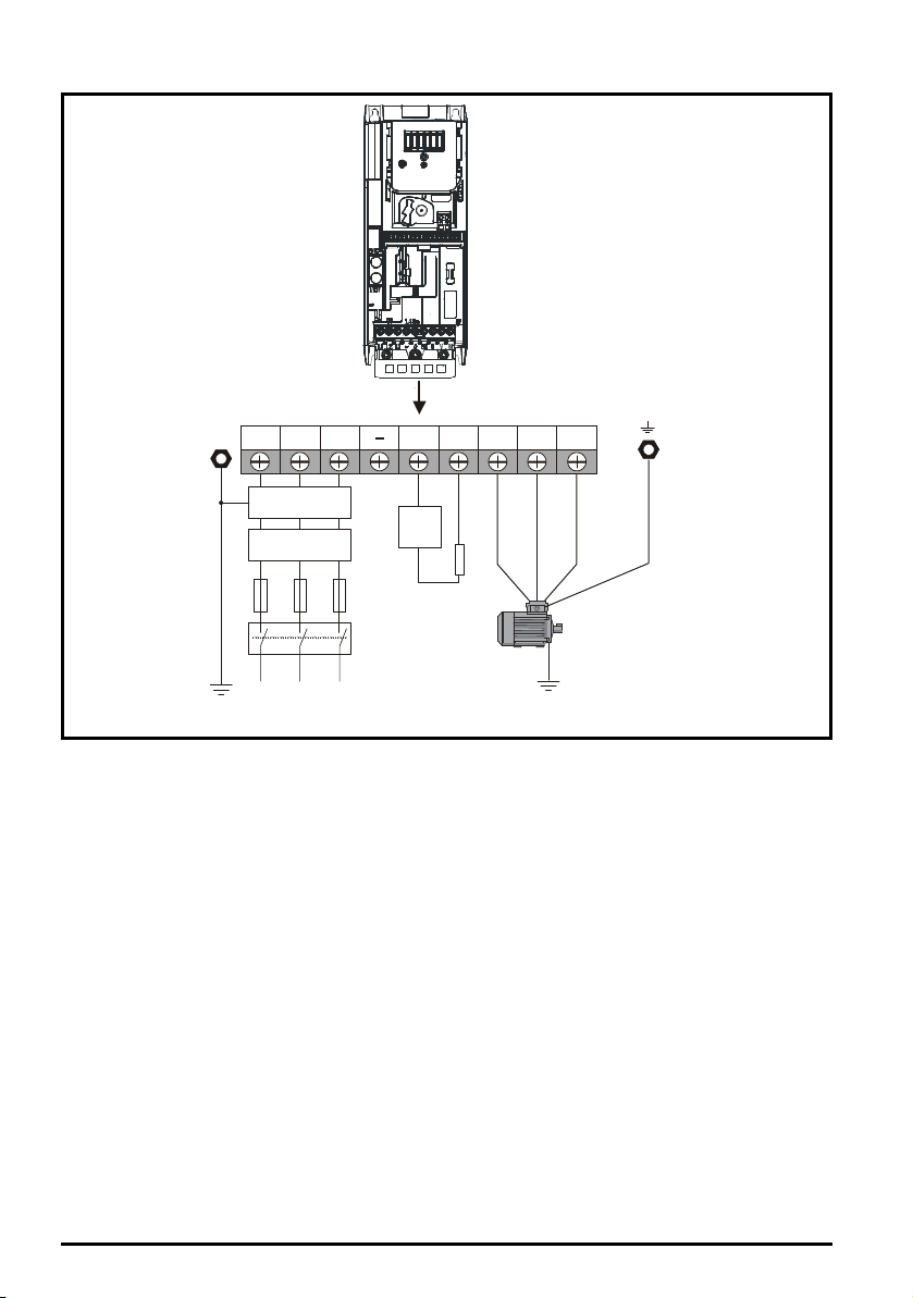
Figure 4-3 Size 3 power connections (Unidrive M400 shown)
L1 L2
L2L1 L3
Optional EMC
filter
Optional
line reactor
Fuses
L3
Mains
Supply
Supply
PE U V
W
Motor
Optional ground
connection
+ BR
Optional
braking
resistor
Thermal
overload
protection
device
Internal
EMC
filter
See Figure 4-5
Size 1 to 4 ground connections (Unidrive M400 size 2 shown)
information on ground connections.
40
Unidrive M100 to M400 Frame 1 to 4 Power Installation Guide
on page 42 for further
Issue Number: 1
Page 41
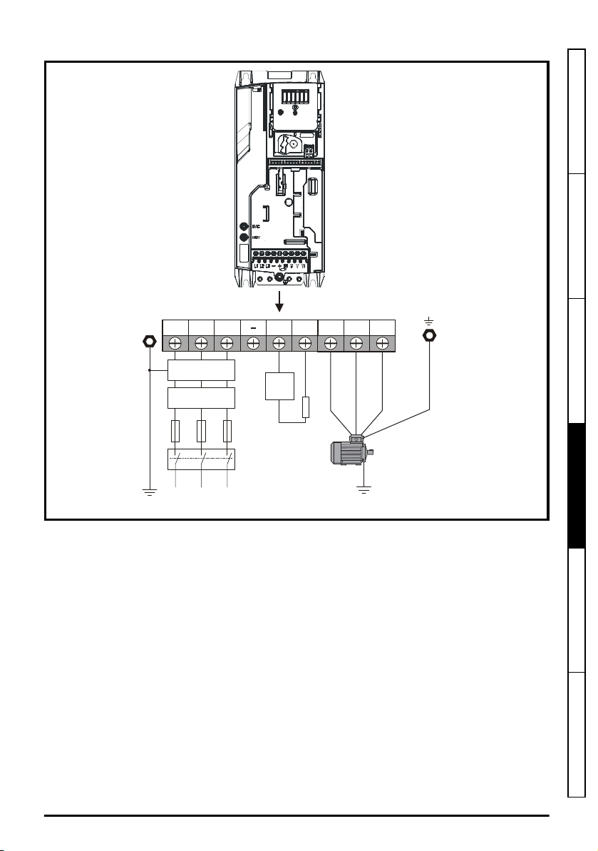
Figure 4-4 Size 4 power connections (Unidrive M400 shown)
L1 L2
L2L1 L3
Optional EMC
filter
Optional
line reactor
Fuses
L3
Mains
Supply
Supply
PE U V
W
Motor
Optional ground
connection
+ BR
Optional
braking
resistor
Thermal
overload
protection
device
Internal
EMC
filter
Safety information Product information Mechanical installation
Electrical installation
See Figure 4-5
Size 1 to 4 ground connections (Unidrive M400 size 2 shown)
information on ground connections.
Unidrive M100 to M400 Frame 1 to 4 Power Installation Guide
Issue Number: 1
on page 42 for further
Technical data UL listing information
41
Page 42

4.1.2 Ground connections
WARNING
1
WARNING
Electrochemical corrosion of grounding terminals
Ensure that grounding terminals are protected against corrosion i.e. as could be caused
by condensation.
Size 1 to 4
The supply and motor ground connections are made using the ground busbar located at the bottom
of the drive as shown in Figure 4-5.
Figure 4-5 Size 1 to 4 ground connections (Unidrive M400 size 2 shown)
1: 4 x M4 threaded holes for the ground connection busbar
The ground loop impedance must conform to the requirements of local safety
regulations.
The drive must be grounded by a connection capable of carrying the prospective fault
current until the protective device (fuse, etc.) disconnects the AC supply.
The ground connections must be inspected and tested at appropriate intervals.
4.1.3 Protective ground cable ratings
Minimum ground conductor size
Either 10 mm2 or two conductors of the same cross-sectional area as the input phase conductor.
42
Unidrive M100 to M400 Frame 1 to 4 Power Installation Guide
Issue Number: 1
Page 43

4.2 AC supply requirements
WARNING
Voltage:
100 V drive: 100 V to 120 V ±10 %
200 V drive: 200 V to 240 V ±10 %
400 V drive: 380 V to 480 V ±10 %
Maximum supply imbalance: 2 % negative phase sequence (equivalent to 3 % voltage imbalance
between phases).
Frequency range: 45 to 66 Hz
For UL compliance only, the maximum supply symmetrical fault current must be limited to 100 kA
4.2.1 Supply types
All drives are suitable for use on any supply type i.e TN-S, TN-C-S, TT and IT.
Drives are suitable for use on supplies of installation category III and lower, according to IEC60664-1.
This means they may be connected permanently to the supply at its origin in a building, but for
outdoor installation additional over-voltage suppression (transient voltage surge suppression) must
be provided to reduce category IV to category III.
Operation with IT (ungrounded) supplies:
Special attention is required when using internal or external EMC filters with ungrounded
supplies, because in the event of a ground (earth) fault in the motor circuit the drive may
not trip and the filter could be over-stressed. In this case, either the filter must not be
used i.e. removed, or additional independent motor ground fault protection must be
provided.
For instructions on removal, refer to Figure 4-13
filter
on page 64 to Figure 4-16
details of ground fault protection contact the supplier of the drive.
A ground fault in the supply has no effect in any case. If the motor must continue to run with a ground
fault in its own circuit then an input isolating transformer must be provided and if an EMC filter is
required it must be located in the primary circuit. Unusual hazards can occur on ungrounded supplies
with more than one source, for example on ships. Contact the supplier of the drive for more
information
Removal of the size 4 internal EMC filter
4.2.2 Supplies requiring line reactors
Input line reactors reduce the risk of damage to the drive resulting from poor phase balance or
severe disturbances on the supply network.
Where line reactors are to be used, reactance values of approximately 2 % are recommended.
Higher values may be used if necessary, but may result in a loss of drive output (reduced torque at
high speed) because of the voltage drop.
For all drive ratings, 2 % line reactors permit drives to be used with a supply unbalance of up to 3.5 %
negative phase sequence (equivalent to 5% voltage imbalance between phases).
Severe disturbances may be caused by the following factors, for example:
• Power factor correction equipment connected close to the drive.
• Large DC drives having no or inadequate line reactors connected to the supply.
• Across the line (DOL) started motor(s) connected to the supply such that when any of these
motors are started, the voltage dip exceeds 20 %.
Such disturbances may cause excessive peak currents to flow in the input power circuit of the drive.
This may cause nuisance tripping, or in extreme cases, failure of the drive.
Drives of low power rating may also be susceptible to disturbance when connected to supplies with a
high rated capacity.
Removal of the size 1 internal EMC
on page 65. For
Safety information Product information Mechanical installation
Electrical installation
Technical data UL listing information
Unidrive M100 to M400 Frame 1 to 4 Power Installation Guide
Issue Number: 1
43
Page 44

Line reactors are particularly recommended for use with the following drive models when one of the
L
Y
100
----------
V
3
-------
×
1
2π fI
------------
×=
above factors exists, or when the supply capacity exceeds 175 kVA: Size 1 to 3.
Model sizes 04200133 to 04400170 have an internal DC choke so they do not require AC line
reactors except for cases of excessive phase unbalance or extreme supply conditions.
When required, each drive must have its own reactor(s). Three individual reactors or a single threephase reactor should be used.
Reactor current ratings
The current rating of the line reactors should be as follows:
Continuous current rating:
Not less than the continuous input current rating of the drive
Repetitive peak current rating:
Not less than twice the continuous input current rating of the drive
4.2.3 Input inductor calculation
To calculate the inductance required (at Y %), use the following equation:
Where:
I
= drive rated input current (A)
L
= inductance (H)
f
= supply frequency (Hz)
V
= voltage between lines
44
Unidrive M100 to M400 Frame 1 to 4 Power Installation Guide
Issue Number: 1
Page 45

4.2.4 Input line reactor specification for size 1 to 4
Table 4-1 AC line reactor values
Drives
used with
01200017
01200024
01200033
01200042
02200024 4402-0224 1 2.25 6.5 13 0.8 72 65 90
02200033
02200056
02200075
04200133
02200024 4401-0224 3 1.96 4.3 8.6 1.1 65 110 70
02200033
02200042
02200056
02200075
03200100
04200176
02400013 4401-0232 3 6.1 2.4 4.8 1.1 65 110 70
02400018
02400023
02400032
02400041
03400056 4401-0149 3 1.62 9.1 18.2 1.8 156 70 125
03400073 4401-0234 3 1.12 13 26 2.5 156 72 114
03400094
04400135
04400170 4401-0235 3 0.71 21 42 3.6 156 68 133
Reactor
part
number
4402-0224 1 2.25 6.5 13 0.8 72 65 90
4402-0225 1 1.0 15.1 30.2 1.1 82 75 100
4402-0225 1 1.0 15.1 30.2 1.1 82 75 10002200042
4402-0226 1 0.5 26.2 52.4 1.5 82 90 10503200100
4401-0225 3 1.12 7.5 15 1.2 80 130 65
4401-0143 3 0.79 13.5 27 1.8 156 70 125
4401-0144 3 0.48 20.6 41.2 2.4 156 80 12504200133
4401-0233 3 5.1 3.5 7 1.2 80 130 65
4401-0148 3 2.94 6.6 13.2 1.3 80 130 75
4401-0151 3 1.05 15.8 31.6 2.6 156 80 125
phases
Input
Inductance
mH A A kg
Continuous
rms
current
Peak
current
Weight
Dimensions
(mm)
L D H
mm mm mm
Safety information Product information Mechanical installation
Electrical installation
Technical data UL listing information
Unidrive M100 to M400 Frame 1 to 4 Power Installation Guide
Issue Number: 1
45
Page 46

Figure 4-6 Input line reactor 4402-0224, 4402-0225 and 4402-0226
A
B
Ground
terminal
C
D
E
B
D
A
M (x4)
C
Table 4-2 Input line reactor dimensions
44.5 mm
(1.75in)
54 mm
(2.13in)
Dimensions
35 mm
(1.38 in)
40 mm
(1.58 in)
53 mm
(2.09 in)
65 mm
(2.56 in)
75 mm
(2.95 in)
90 mm
(3.54 in)
Part No
4402-0224
4402-0226
A B C D E Mounting hole
90 mm
(3.54 in)
100 mm
(3.94 in)
105 mm
(4.13 in)
72 mm
(2.84 in)
82 mm
(3.23 in)
Figure 4-7 Input line reactor
8 mm x 4 mm
(0.32 in x 0.16 in)
Ground
terminal
M34402-0225
46
Unidrive M100 to M400 Frame 1 to 4 Power Installation Guide
Issue Number: 1
Page 47

Table 4-3 Input line reactor dimensions
WARNING
Part number
4401-0224
4401-0225
4401-0143
4401-0144
4401-0232
4401-0233
4401-0148
4401-0149
4401-0234
4401-0151
4401-0235
A B C D E
65 mm
(2.56 in)
80 mm
(3.15 in)
156 mm
(6.14 in)
156 mm
(6.14 in)
65 mm
(2.56 in)
80 mm
(3.15 in)
80 mm
(3.15 in)
156 mm
(6.14 in)
156 mm
(6.14 in)
156 mm
(6.14 in)
156 mm
(6.14 in)
110 mm
(4.33 in)
130 mm
(5.12 in)
125 mm
(4.92 in)
125 mm
(4.92 in)
110 mm
(4.33 in)
130 mm
(5.12 in)
130 mm
(5.12 in)
125 mm
(4.92 in)
114 mm
(4.49 in)
125 mm
(4.92 in)
133 mm
(5.24 in)
70 mm
(2.76 in)
65 mm
(2.56 in)
70 mm
(2.76 in)
80 mm
(3.15 in)
70 mm
(2.76 in)
65 mm
(2.56 in)
75 mm
(2.95 in)
70 mm
(2.76 in)
72 mm
(2.83 in)
80 mm
(3.15 in)
68 mm
(2.68 in)
Dimensions
55 mm
(2.17 in)
60.5 mm
(2.38 in)
140 mm
(5.51 in)
140 mm
(5.51 in)
55 mm
(2.17 in)
60.5 mm
(2.38 in)
60.5 mm
(2.38 in)
140 mm
(5.51 in)
140 mm
(5.51 in)
140 mm
(5.51 in)
140 mm
(5.51 in)
90 mm
(3.54 in)
111 mm
(4.37 in)
83 mm
(3.27 in)
83 mm
(3.27 in)
90 mm
(3.54 in)
111 mm
(4.37 in)
111 mm
(4.37 in)
83 mm
(3.27 in)
83 mm
(3.27 in)
83 mm
(3.27 in)
104 mm
(4.09 in)
Mounting hole
(M)
6 mm x 4 mm
(0.24 in x 0.16 in)
5.8 mm x 9 mm
(0.23 in x 0.35 in)
6 mm x 4 mm
(0.24 in x 0.16 in)
5.8 mm x 9 mm
(0.23 in x 0.35 in)
Safety information Product information Mechanical installation
4.3 Ratings
The input current is affected by the supply voltage and impedance.
Typical input current
The values of typical input current are given to aid calculations for power flow and power loss.
The values of typical input current are stated for a balanced supply.
Maximum continuous input current
The values of maximum continuous input current are given to aid the selection of cables and fuses.
These values are stated for the worst case condition with the unusual combination of stiff supply with
bad balance. The value stated for the maximum continuous input current would only be seen in one
of the input phases. The current in the other two phases would be significantly lower.
The values of maximum input current are stated for a supply with a 2 % negative phase-sequence
imbalance and rated at the supply fault current given in Table 4-4.
Table 4-4 Supply fault current used to calculate maximum input currents
Model Symmetrical fault level (kA)
All 10
Fuses
The AC supply to the drive must be installed with suitable protection against overload and
short-circuits. Table 4-5, Table 4-6 and Table 4-7 show the recommended fuse ratings.
Failure to observe this requirement will cause risk of fire.
Unidrive M100 to M400 Frame 1 to 4 Power Installation Guide
Issue Number: 1
Electrical installation
Technical data UL listing information
47
Page 48
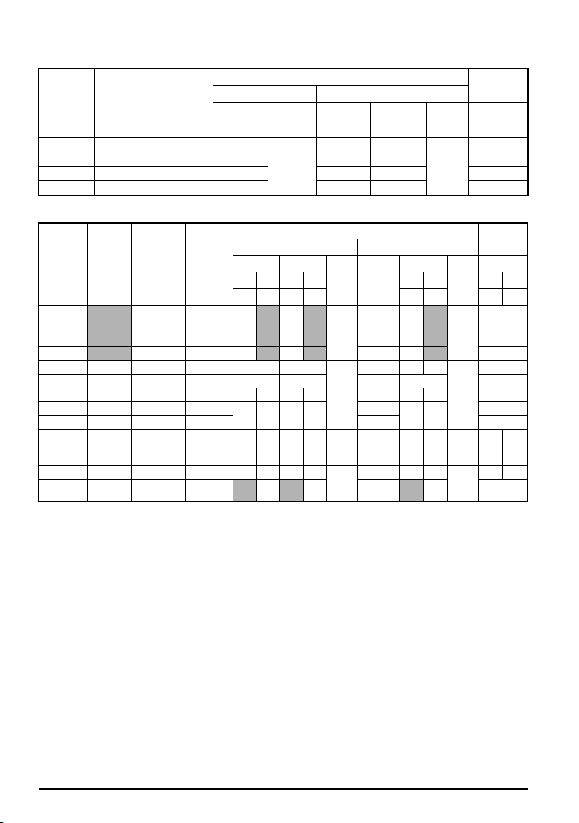
Table 4-5 AC Input current and fuse ratings (100 V)
Class
gG
Fuse rating
Nominal Maximum
15 15
Class
CC, J or
T*
MCB
rating**
Nominal
15
Model
Maximum
continuous
input
current
A A
Maximum
overload
input
current
IEC UL
Maximum
A A A A
01100017 8.7 12.6 10
01100024 11.1 15.2 16 15 15 15
02100042 18.8 28.2 20 20 20 15
02100056 24.0 37.4 25 25 25 15
Table 4-6 AC Input current and fuse ratings (200 V)
Typical
Model
01200017 4.5 6.9 6
01200024 5.3 8.4 6 6 6 15
01200033 8.3 14.2 10 1 0 15 15 15
01200042 10.4 16.8 16 16 15 15 15
02200024 - / 3.2 5.3/4.1 8.1/5.9 6 6
02200033 - / 4.3 8.3/6.7 14/9.2 10 10 10 10 15
02200042 - / 5.4 10.4/7.5 16.4/10.8 16 10 16 10 15/10 15 10 15
02200056 - / 8.1 16.0/12.9 24.0/17.5
02200075 - / 9.1 18.1/13.5 30.4/19.5 20/15 15
03200100 - / 12.8 23.9/17.7 30/25 25 20 25 20
04200133 - / 13.5 23.7/16.9 43.3 /23.5 25 20 25 20
04200176 17.0 21.3 2 8.6 25 25 25 25 25
current
Maximum
continuous
input
input
current
A A A A A A A A A A A A
Maximum
overload
input
current
IEC UL / USA
Nominal Maximum
1ph 3ph 1ph 3ph 1ph 3ph 1ph 3ph
6
20 1 6 20 16
Fuse rating MCB
Maximum
6 6
6 6 6
20/15
20 15
25/20 25 20
25/20 25 20
Class
gG
gG
gG
gG
Nominal
Class
CC, J
or T*
CC,
J or
T*
CC,
J or
T*
CC,
J or
T*
rating
Nominal
15
15
15
25 20
25 20
**
* These are fast acting fuses.
** UL Listed DIVQ / DIVQ7 listed, rated voltage is 600 Vac (for USA and Canada). Short circuit rating
is 10 kA. In other countries, EN IEC circuit breakers can be used with 10 kA supply rating.
48
Unidrive M100 to M400 Frame 1 to 4 Power Installation Guide
Issue Number: 1
Page 49
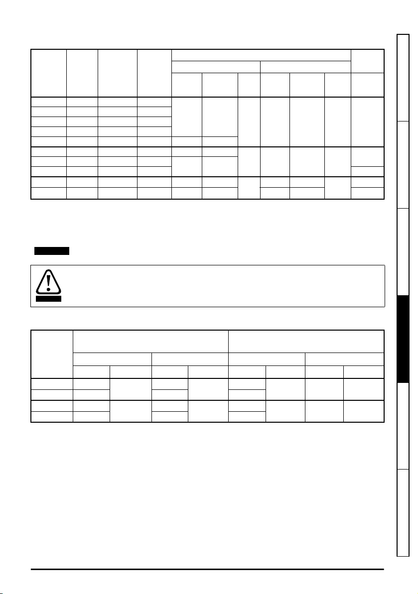
Table 4-7 AC Input current and fuse ratings (400 V)
NOTE
CAUTION
Typical
Model
02400013 2.1 2.4 4.2
02400018 2.6 2.9 5.2
02400023 3.1 3.5 6.1
02400032 4.7 5.1 7.5
02400041 5.8 6.2 9 10 10
03400056 8.3 8.7 13 10 10
03400073 10.2 12.2 1 8
03400094 13.1 14.8 20.7 25
04400135 14.0 16.3 24.7 20 20
04400170 18.5 20.7 32.4 25 25 25 25 25
current
Maximum
continuous
input
A A A A A A A A
input
current
Maximum
overload
input
current
IEC UL / USA
Nominal Maximum
6 6
16 16
Fuse rating MCB
Nominal Maximum
Class
gG 6 6
15 15
gG
20 20
gG
Class
CC, J
or T*
CC, J
or T*
CC, J
or T*
rating
Nominal
**
15
15
20
* These are fast acting fuses.
** UL Listed DIVQ / DIVQ7 listed, rated voltage is 600 Vac (for USA and Canada). Short circuit rating
is 10 kA. In other countries, EN IEC circuit breakers can be used with 10 kA supply rating.
Ensure cables used suit local wiring regulations.
The nominal cable sizes below are only a guide. The mounting and grouping of cables
affects their current-carrying capacity, in some cases smaller cables may be acceptable
but in other cases a larger cable is required to avoid excessive temperature or voltage
drop. Refer to local wiring regulations for the correct size of cables.
Table 4-8 Cable ratings (100 V)
Model
Cable size (IEC 60364-5-52)
Input Output Input Output
mm
2
Nominal Maximum Nominal Maximum Nominal Maximum Nominal Maximum
01100017 1
01100024 1.5 1 14
02100042 2.5
02100056 4 1 10
2.5
4
1
1
2.5
4
16
12
Cable size (UL508C)
AWG
12 16 12
10 16 10
Safety information Product information Mechanical installation
Electrical installation
Technical data UL listing information
Unidrive M100 to M400 Frame 1 to 4 Power Installation Guide
Issue Number: 1
49
Page 50

Table 4-9 Cable ratings (200 V)
NOTE
NOTE
Cable size (IEC 60364-5-52)
Model
01200017
01200024
01200033
01200042
02200024
02200033
02200042
02200056 2.5/1.5 12/14
02200075 2.5 12
03200100 4 4 1.5 4 10/12 10 14 10
04200133 4/2.5
04200176 4
Input Output Input Output
Nominal Maximum Nominal Maximum Nominal Maximum Nominal Maximum
1 2.5 1 2.5 16 12 16 12
1
2
mm
16
4 1 4
4 2.5 4 10 10 12 10
Cable size (UL508C)
AWG
10 16 10
Table 4-10 Cable ratings (400 V)
Cable size (IEC 60364-5-52)
Model
02400013
02400018
02400023
02400032
02400041
03400056 1
03400094 2.5 1.5 14
04400135 2.5
04400170 4
Input Output Input Output
Nominal Maximum Nominal Maximum Nominal Maximum Nominal Maximum
1 4 1 4 16 10 16 10
2
mm
4
4 2.5 4 10 10 12 10
1
4
14
12
Cable size (UL508C)
AWG
10
16
1003400073 1.5
PVC insulated cable should be used.
Cable sizes are from IEC60364-5-52:2001 table A.52.C with correction factor for 40°C
ambient of 0.87 (from table A52.14) for cable installation method B2 (multicore cable in
conduit).
Installation class (ref: IEC60364-5-52:2001)
B1 - Separate cables in conduit.
B2 - Multicore cable in conduit.
C - Multicore cable in free air.
Cable size may be reduced if a different installation method is used, or if the ambient temperature is
lower.
50
Unidrive M100 to M400 Frame 1 to 4 Power Installation Guide
Issue Number: 1
Page 51
The nominal output cable sizes assume that the motor maximum current matches that of
NOTE
NOTE
WARNING
the drive. Where a motor of reduced rating is used the cable rating may be chosen to
match that of the motor. To ensure that the motor and cable are protected against
overload, the drive must be programmed with the correct motor rated current.
A fuse or other protection must be included in all live connections to the AC supply.
Fuse types
The fuse voltage rating must be suitable for the drive supply voltage.
Ground connections
The drive must be connected to the system ground of the AC supply. The ground wiring must
conform to local regulations and codes of practice.
Safety information Product information Mechanical installation
For information on ground cable sizes, refer to Table 4.1.3
ratings
on page 42.
Protective ground cable
4.3.1 Main AC supply contactor
The recommended AC supply contactor type for size 1 to 4 is AC1.
4.4 Output circuit and motor protection
The output circuit has fast-acting electronic short-circuit protection which limits the fault current to
typically no more than 2.5 times the rated output current, and interrupts the current in approximately
20 µs. No additional short-circuit protection devices are required.
The drive provides overload protection for the motor and its cable. For this to be effective,
Current (00.006
) must be set to suit the motor.
Motor Rated Current (00.006
) must be set correctly to avoid a risk of fire in the event of
motor overload.
There is also provision for the use of a motor thermistor to prevent over-heating of the motor, e.g. due
to loss of cooling.
Rated
Electrical installation
Technical data UL listing information
Unidrive M100 to M400 Frame 1 to 4 Power Installation Guide
Issue Number: 1
51
Page 52

4.4.1 Cable types and lengths
Since capacitance in the motor cable causes loading on the output of the drive, ensure the cable
length does not exceed the values given in Table 4-11 to Table 4-13.
Use 105 °C (221 °F) (UL 60/75 °C temp rise) PVC-insulated cable with copper conductors having a
suitable voltage rating, for the following power connections:
• AC supply to external EMC filter (when used)
• AC supply (or external EMC filter) to drive
• Drive to motor
• Drive to braking resistor
Table 4-11 Maximum motor cable lengths (100 V drives)
100 V Nominal AC supply voltage
Model
01100017
01100024
02100042
02100056
Table 4-12 Maximum motor cable lengths (200 V drives)
Model
01200017
01200024
01200033
01200042
02200024
02200033
02200042
02200056
02200075
03200100 100 m (330 ft)
04200133
04200176
Maximum permissible motor cable length for each of the following switching frequencies
0.667 kHz 1kHz 2 kHz 3 kHz 4 kHz 6 kHz 8 kHz 12 kHz 16 kHz
kHz
37.5 m
(122 ft)
75 m
(245 ft)
3
kHz
37.5 m
(122 ft)
75 m
(245 ft)
75 m
(245 ft)
75 m
(245 ft)
75 m (245 ft)
100 m (330 ft)
200 V Nominal AC supply voltage
Maximum permissible motor cable length for each of the following switching frequencies
0.667
kHz
1
kHz
75 m (245 ft)
100 m (330 ft)
100 m (330 ft)
2
kHz
25 m
50 m
6
kHz
25 m
50 m
(165 ft)
50 m
(165 ft)
50 m
(165 ft)
18.75 m
(61.9 ft)
37.5 m
(122 ft)
18.75 m
(61 ft)
37.5 m
(122 ft)
37.5 m
(122 ft)
37.5 m
(122 ft)
(82.5 ft)
(165 ft)
4
(82.5 ft)
8
kHz
12.5 m
(41.25 ft)
25 m
(82.5 ft)
12
kHz16kHz
12.5 m
(41 ft)
25 m
(82.5 ft)
25 m
(82.5 ft)
25 m
(82.5 ft)
9 m
(29.7 ft)
18 m
(59.4ft)
9 m
(30 ft)
18 m
(60 ft)
18 m
(60 ft)
18 m
(60 ft)
52
Unidrive M100 to M400 Frame 1 to 4 Power Installation Guide
Issue Number: 1
Page 53

Table 4-13 Maximum motor cable lengths (400 V drives)
Normal capacitance
Shield or armour
separated from the cores
High capacitance
Shield or armour close
to the cores
400 V Nominal AC supply voltage
Model
02400013
02400018
02400023
02400032
02400041
03400056
03400073
03400094
04400135
04400170
Maximum permissible motor cable length for each of the following switching frequencies
0.667
kHz
1
kHz
100 m (330 ft)
100 m (330 ft)
100 m (330 ft)
kHz
2
3
kHz
4
kHz
75 m
(245 ft)
75 m
(245 ft)
75 m
(245 ft)
6
kHz
50 m
(165 ft)
50 m
(165 ft)
50 m
(165 ft)
8
kHz
37.5 m
(122 ft)
37.5 m
(122 ft)
37.5 m
(122 ft)
12
kHz
25 m
(82.5 ft)
25 m
(82.5 ft)
25 m
(82.5 ft)
16
kHz
18.25 m
(60 ft)
18.25 m
(60 ft)
18.25 m
(60 ft)
4.4.2 High-capacitance / reduced diameter cables
The maximum cable length is reduced from that shown in section 4.4.1
page 52, if high capacitance or reduced diameter motor cables are used.
Most cables have an insulating jacket between the cores and the armor or shield; these cables have
a low capacitance and are recommended. Cables that do not have an insulating jacket tend to have
high capacitance; if a cable of this type is used, the maximum cable length is half that quoted in the
tables, (Figure 4-8 shows how to identify the two types).
Figure 4-8 Cable construction influencing the capacitance
Cable types and lengths
on
Safety information Product information Mechanical installation
Electrical installation
The maximum motor cable lengths specified in section 4.4.1
Cable types and lengths
on page 52 is
shielded and contains four cores. Typical capacitance for this type of cable is 130 pF/m (i.e. from one
core to all others and the shield connected together).
4.4.3 Motor winding voltage
The PWM output voltage can adversely affect the inter-turn insulation in the motor. This is because of
the high rate of change of voltage, in conjunction with the impedance of the motor cable and the
distributed nature of the motor winding.
For normal operation with AC supplies up to 500 Vac and a standard motor with a good quality
insulation system, there is no need for any special precautions. In case of doubt the motor supplier
should be consulted. Special precautions are recommended under the following conditions, but only
if the motor cable length exceeds 10 m:
• AC supply voltage exceeds 500 V
• DC supply voltage exceeds 670 V (i.e. Regenerative / AFE supply)
• Operation of 400 V drive with continuous or very frequent sustained braking
Unidrive M100 to M400 Frame 1 to 4 Power Installation Guide
Issue Number: 1
Technical data UL listing information
53
Page 54
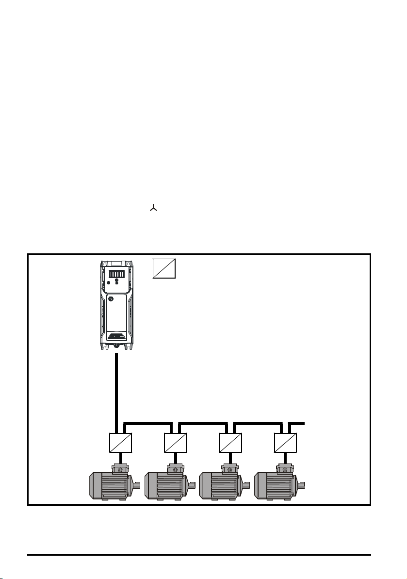
• Multiple motors connected to a single drive
Motor protection
relay
Chain connection (preferred)
For multiple motors, the precautions given in section 4.4.4
For the other cases listed, it is recommended that an inverter-rated motor be used taking into
account the voltage rating of the inverter. This has a reinforced insulation system intended by the
manufacturer for repetitive fast-rising pulsed voltage operation.
If it is not practical to use an inverter-rated motor, an output choke (inductor) should be used. The
recommended type is a simple iron-cored component with a reactance of about 2 %. The exact value
is not critical. This operates in conjunction with the capacitance of the motor cable to increase the
rise-time of the motor terminal voltage and prevent excessive electrical stress.
Multiple motors
should be followed.
4.4.4 Multiple motors
Open-loop only
If the drive is to control more than one motor, one of the fixed V/F modes should be selected
(Pr
05.014
= Fixed or Squared). Make the motor connections as shown in Figure 4-9 and Figure 4-
10. The maximum cable lengths in Table 4-11 to Table 4-13 apply to the sum of the total cable
lengths from the drive to each motor.
It is recommended that each motor is connected through a protection relay since the drive cannot
protect each motor individually. For connection, a sinusoidal filter or an output inductor must be
connected as shown in Figure 4-10, even when the cable lengths are less than the maximum
permissible. For high DC voltages or when supplied by a regen system, a sinusoidal filter is
recommended. For details of filter or inductor sizes refer to the supplier of the drive.
Figure 4-9 Preferred chain connection for multiple motors
54
Unidrive M100 to M400 Frame 1 to 4 Power Installation Guide
Issue Number: 1
Page 55
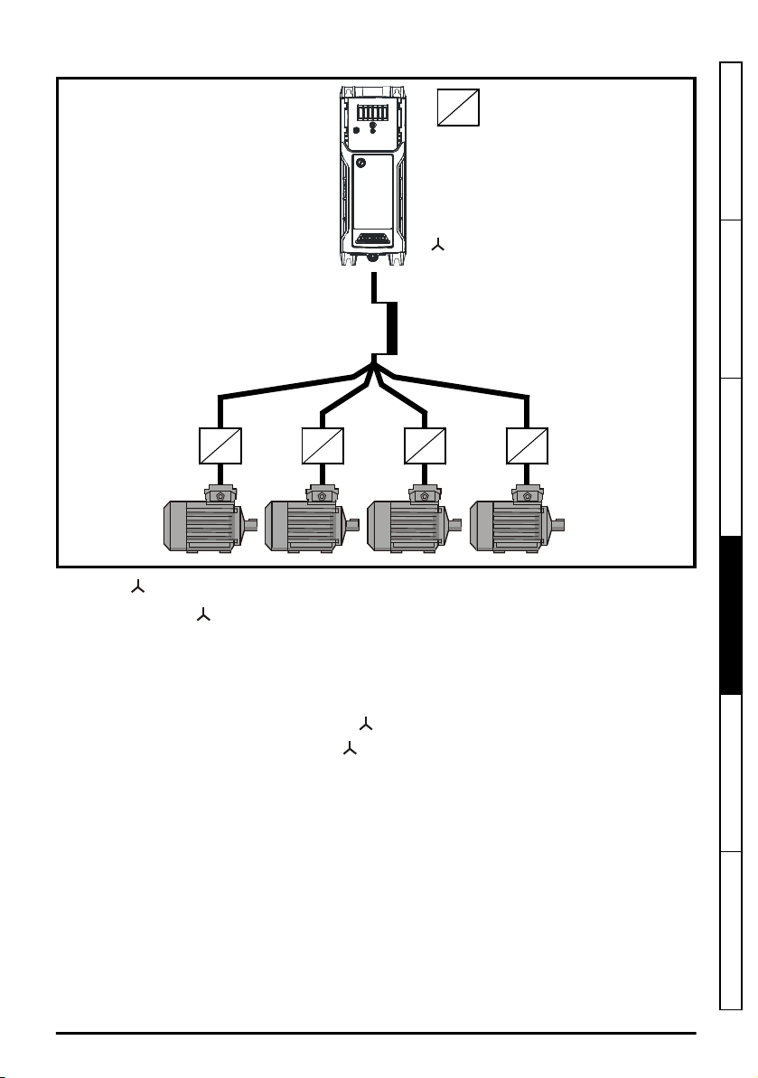
Figure 4-10 Alternative connection for multiple motors
connection
Inductor
Motor protection
relay
2
Safety information Product information Mechanical installation
Electrical installation
4.4.5 /
The voltage rating for and ∆ connections of the motor should always be checked before
attempting to run the motor.
The default setting of the motor rated voltage parameter is the same as the drive rated voltage, i.e.
400 V drive 400 V rated voltage
230 V drive 230 V rated voltage
A typical 3 phase motor would be connected in for 400 V operation or ∆ for 230 V operation,
however, variations on this are common e.g. 690 V ∆ 400 V.
Incorrect connection of the windings will cause severe under or over fluxing of the motor, leading to a
very poor output torque or motor saturation and overheating respectively.
Unidrive M100 to M400 Frame 1 to 4 Power Installation Guide
Issue Number: 1
∆∆∆∆
motor operation
55
Technical data UL listing information
Page 56
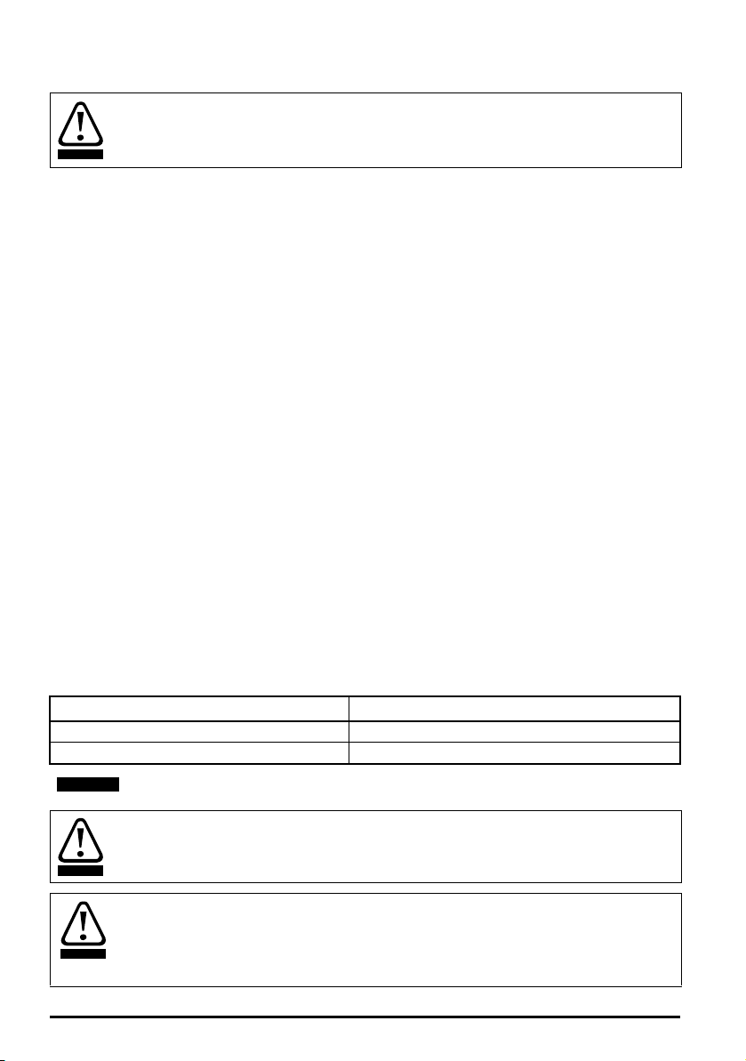
4.4.6 Output contactor
WARNING
NOTE
WARNING
WARNING
If the cable between the drive and the motor is to be interrupted by a contactor or circuit
breaker, ensure that the drive is disabled before the contactor or circuit breaker is opened
or closed. Severe arcing may occur if this circuit is interrupted with the motor running at
high current and low speed.
A contactor is sometimes required to be installed between the drive and motor for safety purposes.
The recommended motor contactor is the AC3 type.
Switching of an output contactor should only occur when the output of the drive is disabled.
Opening or closing of the contactor with the drive enabled will lead to:
1. OI ac trips (which cannot be reset for 10 seconds)
2. High levels of radio frequency noise emission
3. Increased contactor wear and tear
The Drive Enable terminal when opened, provides a Safe Torque Off function (Unidrive M300/M400
only). This can in many cases replace output contactors.
For further information see the
Control User Guide
.
4.5 Braking
Braking occurs when the drive is decelerating the motor, or is preventing the motor from gaining
speed due to mechanical influences. During braking, energy is returned to the drive from the motor.
When motor braking is applied by the drive, the maximum regenerated power that the drive can
absorb is equal to the power dissipation (losses) of the drive.
When the regenerated power is likely to exceed these losses, the DC bus voltage of the drive
increases. Under default conditions, the drive brakes the motor under PI control, which extends the
deceleration time as necessary in order to prevent the DC bus voltage from rising above a user
defined set-point.
If the drive is expected to rapidly decelerate a load, or to hold back an overhauling load, a braking
resistor must be installed.
Table 4-14 shows the default DC voltage level at which the drive turns on the braking transistor.
However the braking resistor turn on and the turn off voltages are programmable with
Lower Threshold
(06.073) and
Braking IGBT Upper Threshold
(06.074).
Table 4-14 Default braking transistor turn on voltage
Drive voltage rating DC bus voltage level
100 & 200 V 390 V
400 V 780 V
Braking IGBT
When a braking resistor is used, Pr
High temperatures
02.004
should be set to Fast ramp mode.
Braking resistors can reach high temperatures. Locate braking resistors so that damage
cannot result. Use cable having insulation capable of withstanding high temperatures.
Braking resistor overload protection parameter settings
Failure to observe the following information may damage the resistor.
The drive software contains an overload protection function for a braking resistor.
For more information on the braking resistor software overload protection, see Pr
Pr
10.031
and Pr
10.061
full descriptions in the
56
Unidrive M100 to M400 Frame 1 to 4 Power Installation Guide
Parameter Reference Guide
.
Issue Number: 1
10.030,
Page 57

4.5.1 External braking resistor
WARNING
Overload protection
When an external braking resistor is used, it is essential that an overload protection device
is incorporated in the braking resistor circuit; this is described in Figure 4-11 on page 59
When a braking resistor is to be mounted outside the enclosure, ensure that it is mounted in a
ventilated metal housing that will perform the following functions:
• Prevent inadvertent contact with the resistor
• Allow adequate ventilation for the resistor
When compliance with EMC emission standards is required, external connection requires the cable
to be armored or shielded, since it is not fully contained in a metal enclosure. See section
4.7.5
Compliance with generic emission standards
Internal connection does not require the cable to be armored or shielded.
Minimum resistance values and peak power rating for the braking resistor at 40 °C (104 °F)
Table 4-15 Braking resistor resistance and power rating (100 V)
Minimum
Model
resistance*
Ω
01100017
01100024 0.37
02100042
02100056 1.1
130 1.1
68 2.2
Table 4-16 Braking resistor resistance and power rating (200 V)
Minimum
Model
resistance*
Ω
01200017
01200024 0.37
01200033 0.55
130 1.1
01200042 0.75
02200024
02200033 0.55
02200042 0.75
02200056 1.1
68 2.2
02200075 1.5
03200100 45 3.3 2.2
04200133
04200176 4
22 6.0
on page 69 for further details.
Instantaneous
power rating
kW
Instantaneous
power rating
kW
Continuous
power rating
kW
0.25
0.75
Continuous
power rating
kW
0.25
0.37
3
Safety information Product information Mechanical installation
.
Electrical installation
Technical data UL listing information
Unidrive M100 to M400 Frame 1 to 4 Power Installation Guide
Issue Number: 1
57
Page 58

Table 4-17 Braking resistor resistance and power rating (400 V)
Model
02400013
02400018 0.55
02400023 0.75
02400032 1.1
02400041 1.5
03400056
03400073 3
03400094 4
04400135
04400170 7.5
* Resistor tolerance: ±10 %
For high-inertia loads or under continuous braking, the
resistor may be as high as the power rating of the drive. The total
resistor is dependent on the amount of energy to be extracted from the load.
The instantaneous power rating refers to the short-term maximum power dissipated during the on
intervals of the pulse width modulated braking control cycle. The braking resistor must be able to
withstand this dissipation for short intervals (milliseconds). Higher resistance values require
proportionately lower instantaneous power ratings.
In most applications, braking occurs only occasionally. This allows the continuous power rating of the
braking resistor to be much lower than the power rating of the drive. It is therefore essential that the
instantaneous power rating and energy rating of the braking resistor are sufficient for the most
extreme braking duty that is likely to be encountered.
Optimization of the braking resistor requires careful consideration of the braking duty.
Select a value of resistance for the braking resistor that is not less than the specified minimum
resistance. Larger resistance values may give a cost saving, as well as a safety benefit in the event
of a fault in the braking system. Braking capability will then be reduced, which could cause the drive
to trip during braking if the value chosen is too large.
Thermal protection circuit for the braking resistor
The thermal protection circuit must disconnect the AC supply from the drive if the resistor becomes
overloaded due to a fault. Figure 4-11 shows a typical circuit arrangement.
Minimum
resistance*
Ω
270 2.2
100 6.0
50 11.2
Instantaneous
power rating
kW
continuous power
energy
Continuous
power rating
kW
0.37
2.2
5.5
dissipated in the braking
dissipated in the braking
58
Unidrive M100 to M400 Frame 1 to 4 Power Installation Guide
Issue Number: 1
Page 59

Figure 4-11 Typical protection circuit for a braking resistor
Optional
EMC
filter
Stop
Start /
Reset
Thermal
protection
device
Braking resistor
Drive
Main contactor
power supply
+DC
BR
See Figure 4-1 on page 38 to Figure 4-4 on page 41 for the location of the +DC and braking resistor
connections.
4.5.2 Braking resistor software overload protection
The drive software contains an overload protection function for a braking resistor. In order to enable
and set-up this function, it is necessary to enter three values into the drive:
•
•
•
This data should be obtained from the manufacturer of the braking resistors.
Pr
indicates the resistor is close to ambient and 100 % is the maximum temperature the resistor can
withstand. A ‘Brake Resistor’ alarm is given if this parameter is above 75 % and the braking IGBT is
active. A Brake R Too Hot trip will occur if Pr
(default value) or 1.
If Pr
but instead the braking IGBT will be disabled until Pr
for applications with parallel connected DC buses where there are several braking resistors, each of
which cannot withstand full DC bus voltage continuously. With this type of application it is unlikely the
braking energy will be shared equally between the resistors because of voltage measurement
tolerances within the individual drives. Therefore with Pr
resistor has reached its maximum temperature the drive will disable the braking IGBT, and another
resistor on another drive will take up the braking energy. Once Pr
drive will allow the braking IGBT to operate again.
See the
Pr
This software overload protection should be used in addition to an external overload protection
device.
Unidrive M100 to M400 Frame 1 to 4 Power Installation Guide
Issue Number: 1
Braking Resistor Rated Power
Braking Resistor Thermal Time Constant
Braking Resistor Resistance
10.039
gives an indication of braking resistor temperature based on a simple thermal model. Zero
10.037
is equal to 2 or 3, a Brake R Too Hot trip will not occur when Pr
Parameter Reference Guide
10.039
.
(10.030)
(10.031)
(10.061)
10.039
reaches 100 %, when Pr
10.039
for more information on Pr
10.037
10.039
reaches 100 %,
falls below 95 %. This option is intended
10.037
set to 2 or 3, then as soon as a
10.039
has fallen below 95 % the
10.030
, Pr
10.031
, Pr
is set to 0
10.037
Safety information Product information Mechanical installation
Electrical installation
Technical data UL listing information
and
59
Page 60

4.6 Ground leakage
NOTE
WARNING
The ground leakage current depends upon whether the internal EMC filter is installed or not. The
drive is supplied with the filter installed. Instructions for removing the internal filter are given in
section 4.7.2
With internal filter installed:
Size 1:
Size 2:
Size 3:
Size 4:
* Proportional to the supply voltage and frequency.
With internal filter removed:
Size 1:
Size 2: 110 V:
Size 3: 230 V:
Internal EMC filter and line to ground varistors (MOVs)
8.1 mA* AC at 110 V 50 Hz
9.5 mA* AC at 230 V 50 Hz
13 mA* AC at 110 V 50 Hz (1 phase)
17.5 mA* AC at 230 V 50 Hz (1 phase)
6.3 mA* AC at 230 V 50 Hz (3 phase)
9.2mA* AC at 415 V 50 Hz (3 phase)
17.1 mA* AC at 230 V 50 Hz (1 phase)
5.9 mA* AC at 230 V 50 Hz (3 phase)
5.7 mA* AC at 415 V 50 Hz (3 phase)
21.3 mA* AC at 230 V 50 Hz (1 phase)
9.7 mA* AC at 230 V 50 Hz (3 phase)
13.3 mA* AC at 415 V 50 Hz (3 phase)
< 1 mA
< 1.2 mA
230 V:
< 1 mA
415 V:
< 2.3 mA
< 1.6 mA
415 V:
< 1 mA
on page 63.
Size 4:
60
< 1 mA
The above leakage currents are just the leakage currents of the drive with the internal
EMC filter connected and do not take into account any leakage currents of the motor or
motor cable.
When the internal filter is installed the leakage current is high. In this case a permanent
fixed ground connection must be provided, or other suitable measures taken to prevent a
safety hazard occurring if the connection is lost.
Unidrive M100 to M400 Frame 1 to 4 Power Installation Guide
Issue Number: 1
Page 61

When the leakage current exceeds 3.5 mA, a permanent fixed ground connection must be
WARNING
WARNING
provided using two independent conductors each with a cross-section equal to or
exceeding that of the supply conductors. The drive is provided with two ground
connections to facilitate this. Both ground connections are necessary to meet EN 618005-1: 2007.
4.6.1 Use of residual current device (RCD)
There are three common types of ELCB / RCD:
1. AC - detects AC fault currents
2. A - detects AC and pulsating DC fault currents (provided the DC current reaches zero at least
once every half cycle)
3. B - detects AC, pulsating DC and smooth DC fault currents
• Type AC should never be used with drives.
• Type A can only be used with single phase drives
• Type B must be used with three phase drives
Only type B ELCB / RCD are suitable for use with 3 phase inverter drives.
If an external EMC filter is used with an ELCB / RCD, a delay of at least 50 ms should be
incorporated to ensure spurious trips are not seen. The leakage current is likely to exceed the trip
level if all of the phases are not energized simultaneously.
4.7 EMC (Electromagnetic compatibility)
The requirements for EMC are divided into three levels in the following three sections:
section 4.7.3
drive and minimise the risk of disturbing nearby equipment. The immunity standards specified in
Chapter 5
Note also the special requirements given in
connections outside a building
control wiring is extended.
section 4.7.4
Systems)
The recommendations of section 4.7.3
avoid causing disturbance to adjacent equipment of industrial quality. If particularly sensitive
equipment is to be used nearby, or in a non-industrial environment, then the recommendations of
section 4.7.4
Systems)
should be followed to give reduced radio-frequency emission.
The correct external EMC filter must be used and all of the guidelines in section 4.7.3
requirements for EMC
must be followed in order to ensure the installation meets the various emission standards described
in:
• The EMC data sheet available from the supplier of the drive
• The Declaration of Conformity at the front of this manual
• Chapter 5
General requirements for EMC
Technical data
on page 75 will be met, but no specific emission standards are applied.
for all applications, to ensure reliable operation of the
Surge immunity of control circuits - long cables and
on page 73 for increased surge immunity of control circuits where
Compliance with IEC 61800-3 (EN 61800-3:2004+A1:2012 standard for Power Drive
section 4.7.5
Compliance with generic emission standards
General requirements for EMC
will usually be sufficient to
Compliance with IEC 61800-3 (EN 61800-3:2004+A1:2012 standard for Power Drive
on page 68 or section 4.7.5
Compliance with generic emission standards
on page 69
General
and section 4.7.5
Technical data
on page 75
Compliance with generic emission standards
on page 69
Safety information Product information Mechanical installation
Electrical installation
Technical data UL listing information
Unidrive M100 to M400 Frame 1 to 4 Power Installation Guide
Issue Number: 1
61
Page 62

Table 4-18 Drive and EMC filter cross reference
WARNING
NOTE
Model CT part number
100 V
01100017 to 01100024 4200-1000, 4200-1001 (low leakage)
02100042 to 02100056 4200-2000
200 V
01200017 to 01200042 4200-1000, 4200-1001 (low leakage)
02200024 to 02200075
03200100
04200133 to 04200176
4200-2001, 4200-2002 (low leakage)
4200-2003, 4200-2004 (low leakage)
4200-3000, 4200-3001 (low leakage)
4200-3004, 4200-3005 (low leakage)
4200-4000, 4200-4001 (low leakage)
4200-4002, 4200-4003 (low leakage)
400 V
02400013 to 02400041 4200-2005, 4200-2006 (low leakage)
03400056 to 03400094 4200-3008, 4200-3009 (low leakage)
04400135 to 04400170 4200-4004, 4200-4005 (low leakage)
High ground leakage current
When an EMC filter is used, a permanent fixed ground connection must be provided which
does not pass through a connector or flexible power cord. This includes the internal EMC
filter.
The installer of the drive is responsible for ensuring compliance with the EMC regulations
that apply in the country in which the drive is to be used.
4.7.1 Grounding hardware
The drive is supplied with a grounding bracket / clamp to facilitate EMC compliance. This provides a
convenient method for direct grounding of cable shields without the use of "pig-tails”. Cable shields
can be bared and clamped to the grounding bracket using metal clips or clamps1 (not supplied) or
cable ties. Note that the shield must in all cases be continued through the clamp to the intended
terminal on the drive, in accordance with the connection details for the specific signal.
1
A suitable clamp is the Phoenix DIN rail mounted SK14 cable clamp (for cables with a maximum
outer diameter of 14 mm).
See Figure 4-12 for details regarding the installation of the grounding bracket.
62
Unidrive M100 to M400 Frame 1 to 4 Power Installation Guide
Issue Number: 1
Page 63

Figure 4-12 Installation of grounding bracket (size 1 to 4)
WARNING
WARNING
Loosen the ground connection screws and slide the grounding bracket in
the direction shown. Once in place, the ground connection screws should be tightened with a
maximum torque of 1.5 N m (1.1 lb ft).
4.7.2 Internal EMC filter and line to ground varistors (MOVs)
It is recommended that the internal EMC filter be kept in place unless there is a specific reason for
removing it.
If the drive is used as a motoring drive as part of a regen system, then the internal EMC filter must be
removed.
The internal EMC filter reduces radio-frequency emission into the line power supply. Where the
motor cable is short, it permits the requirements of EN 61800-3:2004+A1:2012 to be met for the
second environment - see section 4.7.4
standard for Power Drive Systems)
(EMC)
on page 93. For longer motor cables the filter continues to provide a useful reduction in
emission levels, and when used with any length of shielded motor cable up to the limit for the drive, it
is unlikely that nearby industrial equipment will be disturbed. It is recommended that the filter be used
in all applications unless the instructions given above require it to be removed, or where the ground
leakage current is unacceptable. As shown in Figure 4-13 to Figure 4-16, the internal EMC filter is
removed by removing the screw (1).
Compliance with IEC 61800-3 (EN 61800-3:2004+A1:2012
on page 68 and section 5.1.25
Electromagnetic compatibility
Safety information Product information Mechanical installation
Electrical installation
Technical data UL listing information
The supply must be disconnected before removing the internal EMC filter.
The line to ground varistors should only be removed in special circumstances such as
ungrounded supplies with more than one source, for example on ships. Where the line to
ground varistors are removed, ensure that line to ground transients are limited to values
of category II. This is to ensure that line to ground transients do not exceed 4 kV as the
drive insulation system from power to ground is designed to category II.Contact the
supplier of the drive for more information.
Unidrive M100 to M400 Frame 1 to 4 Power Installation Guide
Issue Number: 1
63
Page 64
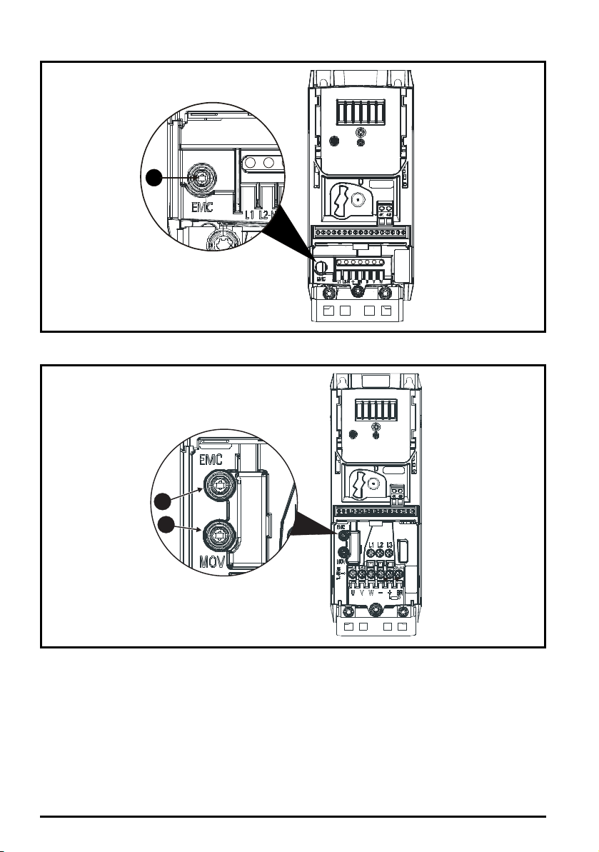
Figure 4-13 Removal of the size 1 internal EMC filter
1
1
2
To electrically disconnect the internal EMC filter, remove the screw as shown above (1).
Figure 4-14 Removal of the size 2 internal EMC filter and Varistor (MOV)
• To electrically disconnect the internal EMC filter, remove the screw as shown above (1).
• To electrically disconnect the varistor (MOV), remove the screw as shown above (2).
64
Unidrive M100 to M400 Frame 1 to 4 Power Installation Guide
Issue Number: 1
Page 65
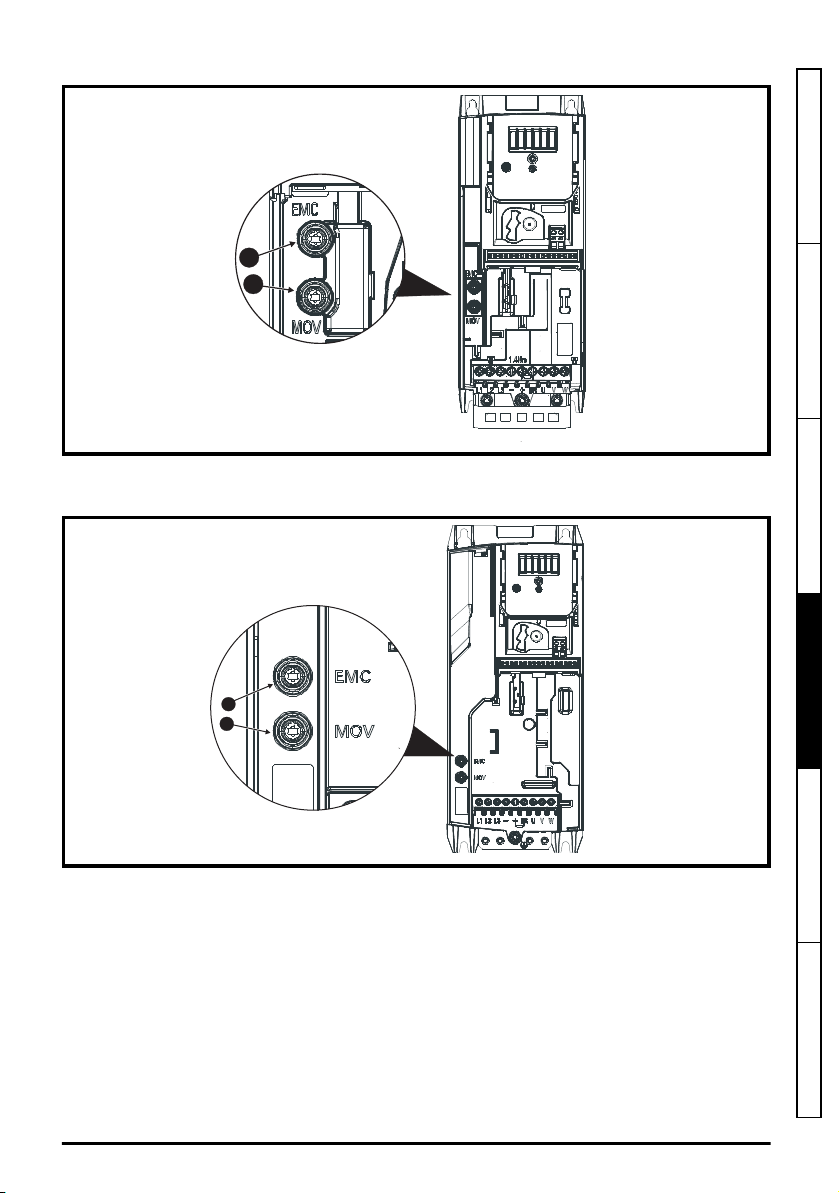
Figure 4-15 Removal of the size 3 internal EMC filter and line to ground varistors (MOV)
1
2
1
2
• To electrically disconnect the internal EMC filter, remove the screw as shown above (1).
• To electrically disconnect the line to ground varistor (MOV), remove the screw as shown above (2).
Figure 4-16 Removal of the size 4 internal EMC filter
Safety information Product information Mechanical installation
Electrical installation
• To electrically disconnect the internal EMC filter, remove the screw as shown above (1).
• To electrically disconnect the line to ground varistor (MOV), remove the screw as shown above (2).
4.7.3 General requirements for EMC
Ground (earth) connections
The grounding arrangements should be in accordance with Figure 4-17, which shows a single drive
on a back-plate with or without an additional enclosure.
Figure 4-17 shows how to configure and minimise EMC when using unshielded motor cable.
However shielded cable is a better option, in which case it should be installed as shown in section
4.7.5
Compliance with generic emission standards
Unidrive M100 to M400 Frame 1 to 4 Power Installation Guide
Issue Number: 1
on page 69.
Technical data UL listing information
65
Page 66
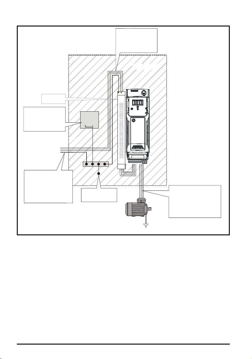
Figure 4-17 General EMC enclosure layout showing ground connections
Optional
ground
External
controller
0V
If the control circuit 0V
is to be grounded, this
should be done at the
system controller only to
avoid injecting noise
currents into the 0V circuit
Metal backplate
Grounding bar
PE
~
PE
If ground connections are
made using a separate
cable, they should run
parallel to the appropriate
power cable to minimise
emissions
Use four core cable to
connect the motor to the drive.
The ground conductor in the
motor cable must be connected
directly to the earth terminal of
the drive and motor.
It must not be connected directly
to the power earth busbar.
The incoming supply ground
should be connected to a
single power ground bus bar
or low impedance earth
terminal inside the cubicle.
This should be used as a
common 'clean' ground for all
components inside the cubicle.
3 phase AC supply
Optional EMC
filter
Metal backplate
safety bonded to
power ground busbar
Cable layout
Figure 4-18 indicates the clearances which should be observed around the drive and related ‘noisy’
power cables by all sensitive control signals / equipment.
66
Unidrive M100 to M400 Frame 1 to 4 Power Installation Guide
Issue Number: 1
Page 67
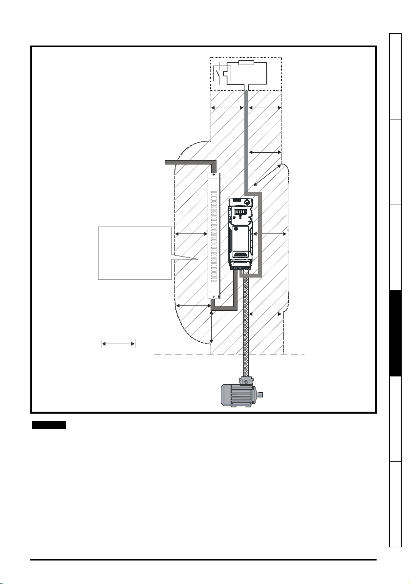
Figure 4-18 Drive cable clearances
Optional braking resistor and overload
Do not place sensitive
(unscreened) signal circuits
within a zone extending
300 mm (12 in) around the
Drive, motor cable, or input
cable from the EMC filter and
unshielded braking resistor
cable (if used)
300 mm
(12 in)
NOTE
Safety information Product information Mechanical installation
Electrical installation
Any signal cables which are carried inside the motor cable (i.e. motor thermistor, motor
brake) will pick up large pulse currents via the cable capacitance. The shield of these
signal cables must be connected to ground close to the motor cable, to avoid this noise
current spreading through the control system.
N
Unidrive M100 to M400 Frame 1 to 4 Power Installation Guide
Issue Number: 1
Technical data UL listing information
67
Page 68
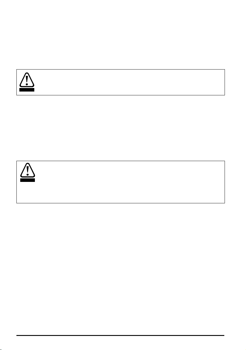
4.7.4 Compliance with IEC 61800-3 (EN 61800-3:2004+A1:2012 standard for
CAUTION
CAUTION
Power Drive Systems)
Meeting the requirements of this standard depends on the environment that the drive is intended to
operate in, as follows:
Operation in the first environment
Observe the guidelines given in section 4.7.5
page 69. An external EMC filter will always be required.
This is a product of the restricted distribution class according to EN 618003:2004+A1:2012
In a residential environment this product may cause radio interference in which case the
user may be required to take adequate measures.
Operation in the second environment
In all cases a shielded motor cable must be used, and an EMC filter is required for all drives with a
rated input current of less than 100 A.
The drive contains an in-built filter for basic emission control. In some cases feeding the motor cables
(U, V and W) once through a ferrite ring can maintain compliance for longer cable lengths.
For longer motor cables, an external filter is required. Where a filter is required, follow the guidelines
in section 4.7.5
Compliance with generic emission standards
Where a filter is not required, follow the guidelines given in section 4.7.3
EMC
on page 65.
The second environment typically includes an industrial low-voltage power supply network
which does not supply buildings used for residential purposes. Operating the drive in this
environment without an external EMC filter may cause interference to nearby electronic
equipment whose sensitivity has not been appreciated. The user must take remedial
measures if this situation arises. If the consequences of unexpected disturbances are
severe, it is recommended that the guidelines in section 4.7.5
emission standards
Refer to section 5.1.25
on page 69 be adhered to.
Electromagnetic compatibility (EMC)
compliance with EMC standards and definitions of environments.
Detailed instructions and EMC information are given in the
the supplier of the drive.
Compliance with generic emission standards
on page 69.
General requirements for
Compliance with generic
on page 93 for further information on
EMC Data Sheet
which is available from
on
68
Unidrive M100 to M400 Frame 1 to 4 Power Installation Guide
Issue Number: 1
Page 69
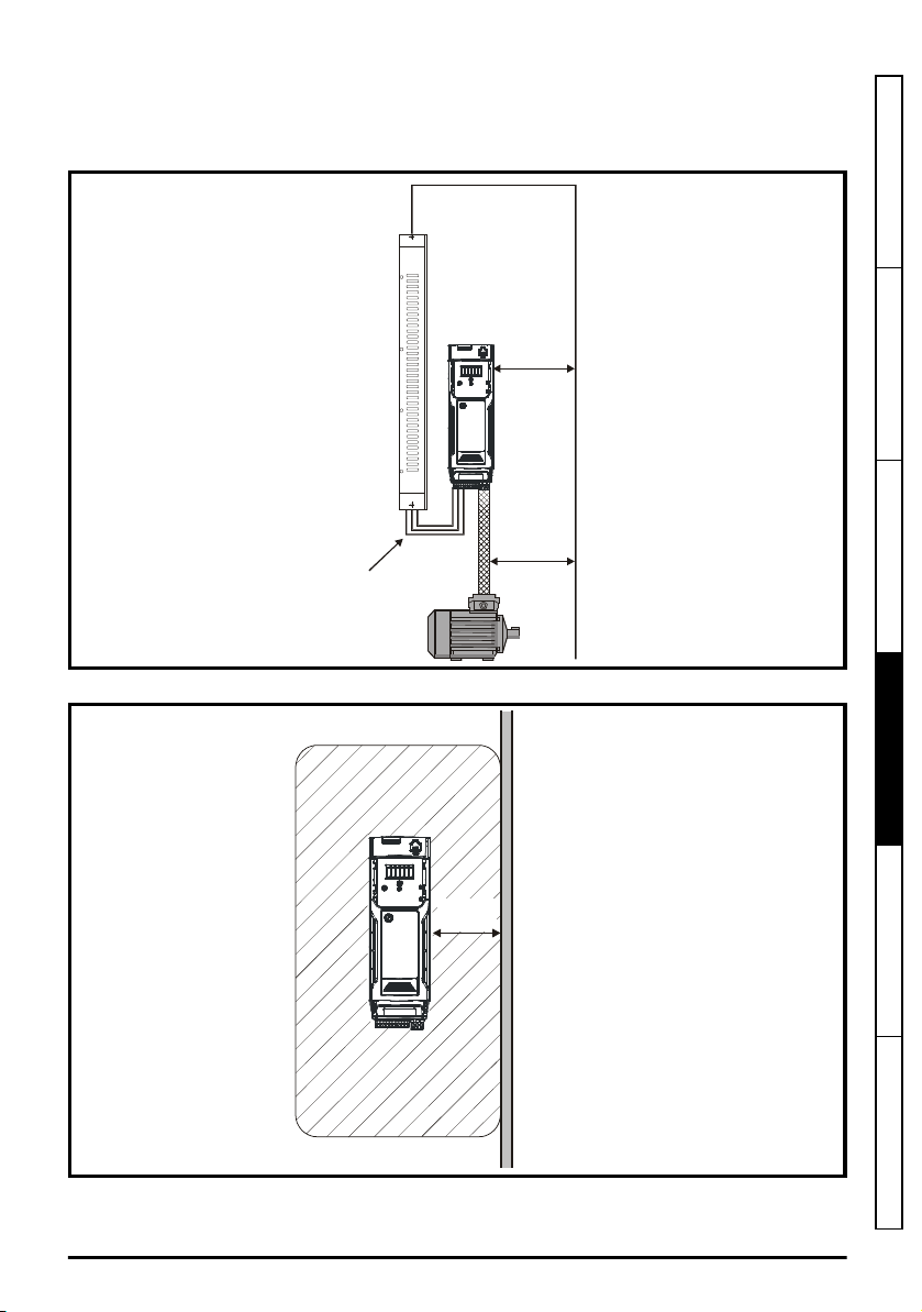
4.7.5 Compliance with generic emission standards
≥
100 mm
(4 in)
≥
100 mm
(4 in)
Do not modify
the filter wires
Sensitive
signal
cable
≥
300 mm
(12 in)
Use the recommended filter and shielded motor cable. Observe the layout rules given in Figure 4-19.
Ensure the AC supply and ground cables are at least 100 mm from the power module and motor cable.
Figure 4-19 Supply and ground cable clearance (sizes 1 to 4)
Figure 4-20 Sensitive signal circuit clearance
Safety information Product information Mechanical installation
Electrical installation
Ensure good EMC grounding.
Unidrive M100 to M400 Frame 1 to 4 Power Installation Guide
Issue Number: 1
Technical data UL listing information
69
Page 70
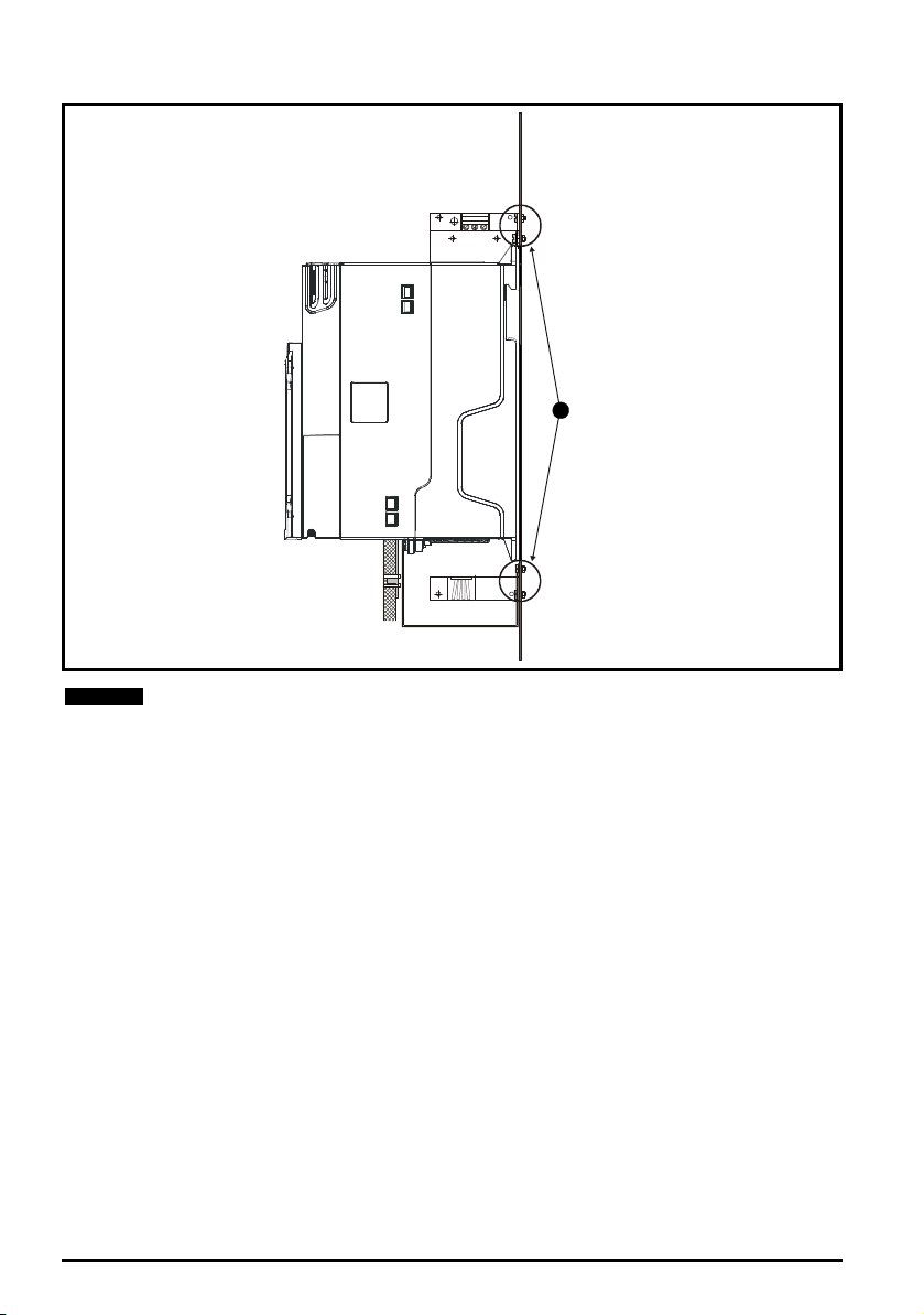
Figure 4-21 Grounding the drive, motor cable shield and filter
1
NOTE
1. Ensure direct metal contact at the drive and filter mounting points. Any paint must be
removed beforehand.
The unbroken motor cable shield (unbroken) electrically connected to and held in place
by means of the grounding bracket.
Connect the shield of the motor cable to the ground terminal of the motor frame using a
link that is as short as possible and not exceeding 50 mm (2 in) long.
A complete 360° termination of the shield to the terminal housing of the motor is
beneficial.
From an EMC consideration it is irrelevant whether the motor cable contains an internal
(safety) ground core, or if there is a separate external ground conductor, or where
grounding is through the shield alone. An internal ground core will carry a high noise
current and therefore it must be terminated as close as possible to the shield termination.
70
Unidrive M100 to M400 Frame 1 to 4 Power Installation Guide
Issue Number: 1
Page 71
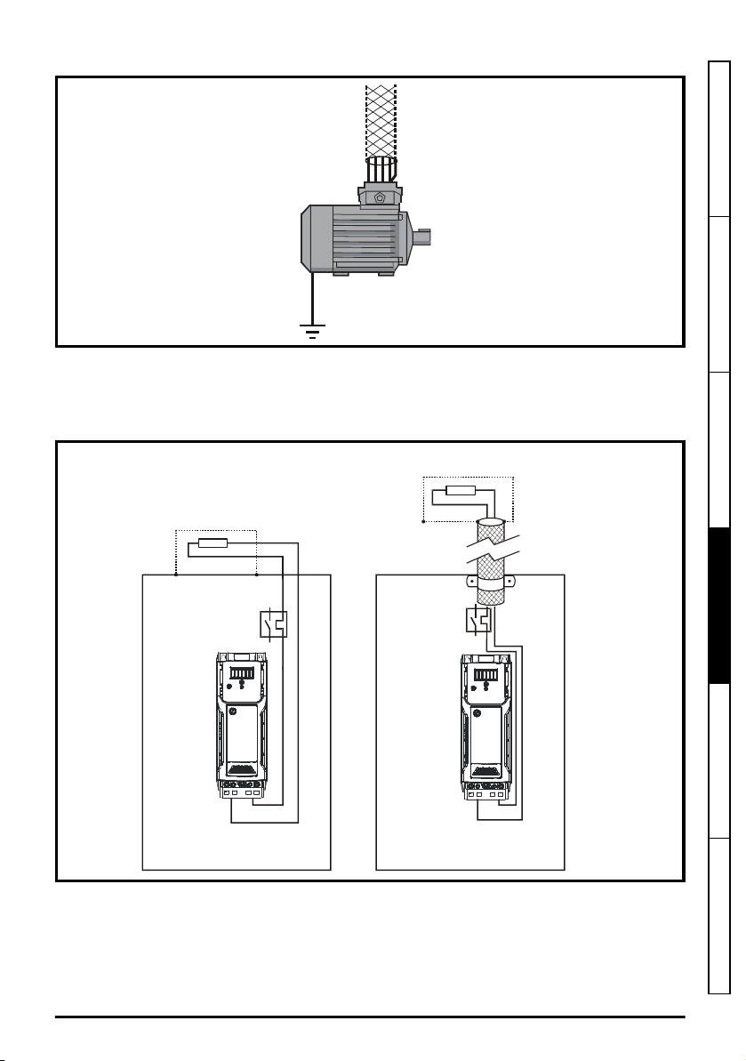
Figure 4-22 Grounding the motor cable shield
+DC+DC BRBR
Optional external
braking resistor
Enclosure
OR
+DC
BR
Optional external
braking resistor
Enclosure
Unshielded wiring to the optional braking resistor(s) may be used provided the wiring runs internally
to the enclosure. Ensure a minimum spacing of 300 mm (12 in) from the signal wiring and the AC
supply wiring to the external EMC filter. If this condition cannot be met then the wiring must be
shielded.
Figure 4-23 Shielding requirements of optional external braking resistor
Safety information Product information Mechanical installation
Electrical installation
If the control wiring is to leave the enclosure, it must be shielded and the shield(s) clamped to the
drive using the grounding bracket as shown in Figure 4-24. Remove the outer insulating cover of the
cable to ensure the shield(s) make direct contact with the bracket, but keep the shield(s) intact until
as close as possible to the terminals
Alternatively, wiring may be passed through a ferrite ring, part number
3225-1004.
Unidrive M100 to M400 Frame 1 to 4 Power Installation Guide
Issue Number: 1
Technical data UL listing information
71
Page 72
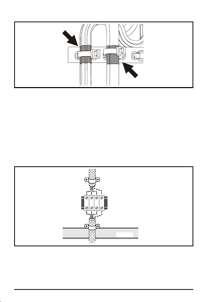
Figure 4-24 Grounding of signal cable shields using the grounding bracket
From the Drive
To the motor
Back-plate
Enclosure
4.7.6 Variations in the EMC wiring
Interruptions to the motor cable
The motor cable should ideally be a single length of shielded or armored cable having no
interruptions. In some situations it may be necessary to interrupt the cable, as in the following
examples:
• Connecting the motor cable to a terminal block in the drive enclosure
• Installing a motor isolator / disconnect switch for safety when work is done on the motor
In these cases the following guidelines should be followed.
Terminal block in the enclosure
The motor cable shields should be bonded to the back-plate using uninsulated metal cable-clamps
which should be positioned as close as possible to the terminal block. Keep the length of power
conductors to a minimum and ensure that all sensitive equipment and circuits are at least 0.3 m (12
in) away from the terminal block.
Figure 4-25 Connecting the motor cable to a terminal block in the enclosure
Using a motor isolator / disconnect-switch
The motor cable shields should be connected by a very short conductor having a low inductance.
The use of a flat metal coupling-bar is recommended; conventional wire is not suitable.
The shields should be bonded directly to the coupling-bar using uninsulated metal cable-clamps.
Keep the length of the exposed power conductors to a minimum and ensure that all sensitive
equipment and circuits are at least 0.3 m (12 in) away.
72
Unidrive M100 to M400 Frame 1 to 4 Power Installation Guide
Issue Number: 1
Page 73
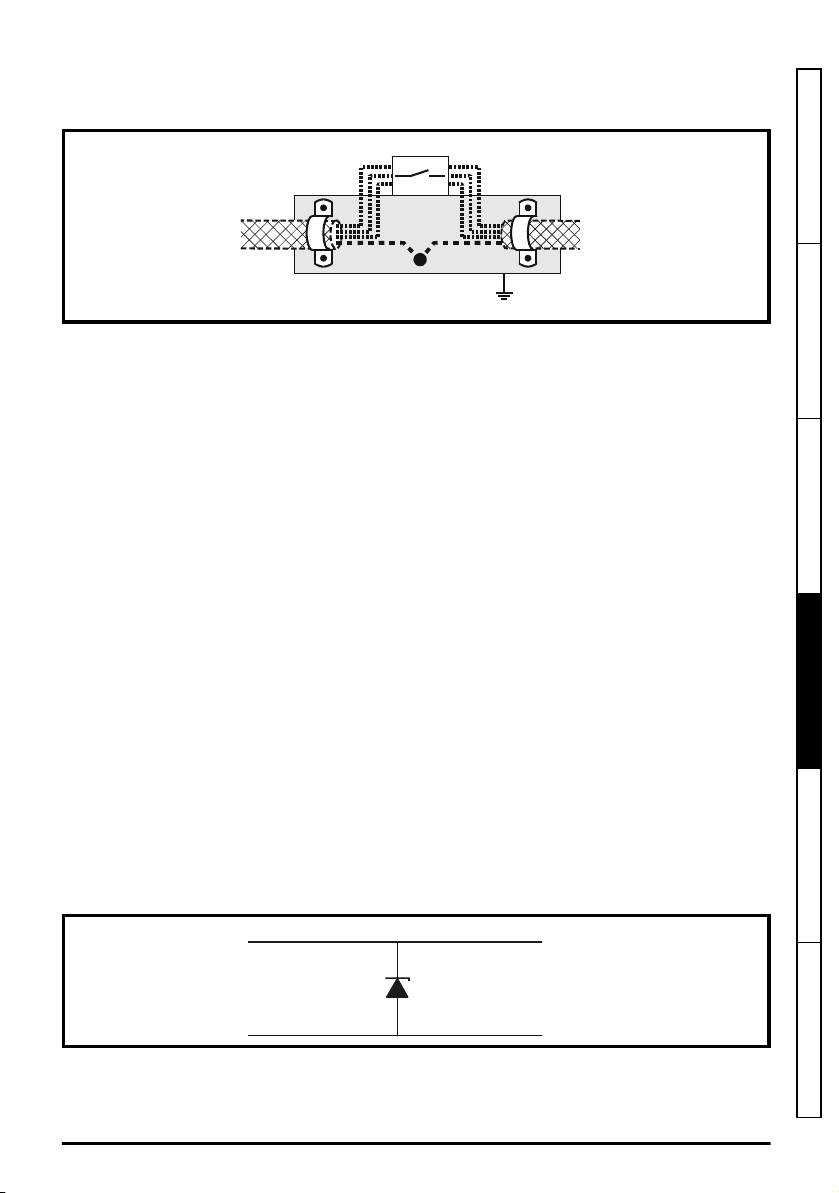
The coupling-bar may be grounded to a known low-impedance ground nearby, for example a large
Isolator
Coupling bar
From the
Drive
To the
motor
(If required)
Signal from plant Signal to drive
0V 0V
30V zener diode
e.g. 2xBZW50-15
metallic structure which is connected closely to the drive ground.
Figure 4-26 Connecting the motor cable to an isolator / disconnect switch
Surge immunity of control circuits - long cables and connections outside a building
The input/output ports for the control circuits are designed for general use within machines and small
systems without any special precautions.
These circuits meet the requirements of EN 61000-6-2:2005 (1 kV surge) provided the 0 V
connection is not grounded.
In applications where they may be exposed to high-energy voltage surges, some special measures
may be required to prevent malfunction or damage. Surges may be caused by lightning or severe
power faults in association with grounding arrangements which permit high transient voltages
between nominally grounded points. This is a particular risk where the circuits extend outside the
protection of a building.
As a general rule, if the circuits are to pass outside the building where the drive is located, or if cable
runs within a building exceed 30 m, some additional precautions are advisable. One of the following
techniques should be used:
1. Galvanic isolation, i.e. do not connect the control 0 V terminal to ground. Avoid loops in the
control wiring, i.e. ensure every control wire is accompanied by its return (0 V) wire.
2. Shielded cable with additional power ground bonding. The cable shield may be connected to
ground at both ends, but in addition the ground conductors at both ends of the cable must be
bonded together by a power ground cable (equipotential bonding cable) with cross-sectional
area of at least 10 mm2, or 10 times the area of the signal cable shield, or to suit the electrical
safety requirements of the plant. This ensures that fault or surge current passes mainly through
the ground cable and not in the signal cable shield. If the building or plant has a well-designed
common bonded network this precaution is not necessary.
3. Additional over-voltage suppression - for the analog and digital inputs and outputs, a zener diode
network or a commercially available surge suppressor may be connected in parallel with the
input circuit as shown in Figure 4-27 and Figure 4-28.
If a digital port experiences a severe surge its protective trip may operate (I/O Overload trip). For
continued operation after such an event, the trip can be reset automatically by setting Pr
10.034
to 5.
Figure 4-27 Surge suppression for digital and unipolar inputs and outputs
Safety information Product information Mechanical installation
Electrical installation
Technical data UL listing information
Unidrive M100 to M400 Frame 1 to 4 Power Installation Guide
Issue Number: 1
73
Page 74

Figure 4-28 Surge suppression for analog and bipolar inputs and outputs
Signal from plant Signal to drive
0V 0V
2 x 15V zener diode
e.g. 2xBZW50-15
Surge suppression devices are available as rail-mounting modules, e.g. from Phoenix Contact:
Unipolar TT-UKK5-D/24 DC
Bipolar TT-UKK5-D/24 AC
These devices are not suitable for encoder signals or fast digital data networks because the
capacitance of the diodes adversely affects the signal. Most encoders have galvanic isolation of the
signal circuit from the motor frame, in which case no precautions are required. For data networks,
follow the specific recommendations for the particular network.
74
Unidrive M100 to M400 Frame 1 to 4 Power Installation Guide
Issue Number: 1
Page 75

5
Technical data
5.1 Drive technical data
5.1.1 Power and current ratings (Derating for switching frequency and
For a full explanation of ‘Normal Duty’ and ‘Heavy Duty’ refer to the
Table 5-1 Maximum permissible continuous output current @ 40 °C (104 °F) ambient
100 V
200 V
400 V
temperature)
Control User Guide
Heavy Duty
Model
01100017 0.25 0.33 1.7
01100024 0.37 0.5 2.4
02100042 0.75 1.0 4.2
02100056 1.1 1.5 5.6
01200017 0.25 0.33 1.7
01200024 0.37 0.5 2.4
01200033 0.55 0.75 3.3
01200042 0.75 1.0 4.2
02200024 0.37 0.5 2.4
02200033 0.55 0.75 3.3
02200042 0.75 1.0 4.2
02200056 1.1 1.5 5.6
02200075 1.5 2.0 7.5 7.0
03200100 2.2 3.0 10 9 7.3
04200133 3.0 3.0 13.3
04200176 4.0 5.0 17.6 17.0
02400013 0.37 0.5 1.3 1.3 1.3 1.3 1.3 1.3 1.3 1.3
02400018 0.55 0.75 1.8 1.8 1.8 1.8 1.8 1.8 1.8 1.8
02400023 0.75 1.0 2.3 2.3 2.3 2.3 2.3 2.3 2.3 2.0
02400032 1.1 1.5 3.2 3.2 3.2 3.2 3.2 3.2 3.2 2.0
02400041 1.5 2.0 4.1 4.1 4.1 4.1 4.1 4.1 3.8 2.0
03400056 2.2 3.0 5.6 5.6 5.6 5.6 5.6 5.6 5.1 3.7 2.4
03400073 3.0 3.0 7.3 7.3 7.3 7.3 7.3 7.1 5.6 3.8
03400094 4.0 5.0 9.4 9.4 9.4 9.4 9.4 8.5 7 4.6
04400135 5.5 7.5 13.5 10.7
04400170 7.5 10.0 17 13.5 10.7
Nominal
rating
kW hp
Maximum permissible continuous output current (A) for the following
switching frequencies
0.667
kHz1kHz2kHz3kHz4kHz6kHz8kHz12kHz
.
16
kHz
Safety information Product information Mechanical installation Electrical installation
Technical data
UL listing information
Unidrive M100 to M400 Frame 1 to 4 Power Installation Guide
Issue Number: 1
75
Page 76

Table 5-2 Maximum permissible continuous output current @ 50 °C (122 °F) (size 1 to 4)
NOTE
Heavy Duty
Model
0.667
kHz
100 V
01100017* 1.7
01100024* 2.4
02100042 4.2
02100056 5.6 5.5 5.3 5.1 4.9
200 V
01200017* 1.7
01200024* 2.4
01200033* 3.3
01200042* 4.2
02200024 2.4
02200033 3.3
02200042 4.2 4.0
02200056 5.6 5.6 5.6 5.6 5.6 5.6 5.6 5.6 5.4
02200075 7.5 7.5 7.4 7.2 6.8 6.6 6.3 5.8 5.4
03200100 10 10 10 10 9.5 8.6 7.5 6.1 5
04200133 13.3
04200176 17.6 17 15.5
400 V
02400013 1.3 1.3 1.3 1.3 1.3 1.3 1.3 1.1
02400018 1.8 1.8 1.8 1.8 1.8 1.8 1.8 1.1
02400023 2.3 2.3 2.3 2.3 2.3 2.3 2.3 1.1
02400032 3.2 3.2 3.2 3.2 3.2 3.2 2.5 1.1
02400041 4.1 4.1 4.1 4.1 3.7 3.2 2.5 1.1
03400056 5.6 5.6 5.6 5.6 5 3.5 2.8 1.9
03400073 7.3 7.3 7.3 7.3 6.2 4.5 3.4
03400094 9.4 9.4 9.4 9.4 7.9 6.2 4.7
04400135 13.5 12 9.3
04400170 17 15.3 15.2 12 9.3
Maximum permissible continuous output current (A)
for the following switching frequencies
1
kHz
2
kHz3kHz4kHz6kHz
8
kHz
12
kHz
16
kHz
* CI-Keypad not installed.
Ratings at 55 °C are available on request.
76
Unidrive M100 to M400 Frame 1 to 4 Power Installation Guide
Issue Number: 1
Page 77

5.1.2 Power dissipation
Table 5-3 Losses @ 40 °C (104 °F) ambient (size 1 to 4)
Heavy Duty
Model
100 V
01100017 0.25 0.33 23 23 24 24 25 27 28 32 35
01100024 0.37 0.5 27 27 29 30 31 33 35 39 44
02100042 0.75 1.0 39 40 41 42 43 45 47 51 55
02100056 1.1 1.5 51 51 53 54 55 58 61 67 73
200 V
01200017 0.25 0.33 21 21 22 22 23 25 27 30 33
01200024 0.37 0.5 24 25 26 27 28 30 33 37 41
01200033 0.55 0.75 31 32 33 35 36 39 42 47 53
01200042 0.75 1.0 38 39 40 42 44 47 51 58 65
02200024 0.37 0.5 25 25 25 26 26 28 29 31 33
02200033 0.55 0.75 32 33 33 34 35 36 38 41 44
02200042 0.75 1.0 39 40 41 42 43 45 47 51 55
02200056 1.1 1.5 46 47 48 50 51 54 57 63 69
02200075 1.5 2.0 62 62 65 67 69 73 77 86 87
03200100 2.2 3.0 85 87 91 96 101 110 117 121 117
04200133
04200176 4.0 5.0 149 150 156 161 166 176 186 207 220
400 V
02400013 0.37 0.5 25 26 30 33 36 42 48 60
02400018 0.55 0.75 29 30 34 37 40 47 53 67
02400023 0.75 1.0 33 34 38 41 45 52 59 69
02400032 1.1 1.5 41 42 46 50 54 63 71 70
02400041 1.5 2.0 49 50 55 60 64 74 78 70
03400056 2.2 3.0 55 57 62 68 75 86 90 86 77
03400073 3.0 3.0 72 74 82 90 98 113 101 92
03400094 4.0 5.0 95 99 108 116 129 128 125 113
04400135 5.5 7.5 142 146 159 172 169 196 239 294 292
04400170 7.5 10.0 165 170 186 202 218 251 284 294 292
Nominal rating
kW hp
3.0 3.0 101 102 106 110 114 121 129 144 160
*
Drive losses (W) taking into account any current derating for the given
conditions
0.667
kHz1kHz2kHz3kHz4kHz6kHz8kHz12kHz
Safety information Product information Mechanical installation Electrical installation
16
kHz
Technical data
UL listing information
* Different losses with single-phase supply (available on request).
Unidrive M100 to M400 Frame 1 to 4 Power Installation Guide
Issue Number: 1
77
Page 78

Table 5-4 Losses @ 50°C (122°F) ambient (size 1 to 4)
Heavy Duty
Model
100 V
01100017 0.25 0.33 23 23 24 24 25 27 28 32 35
01100024 0.37 0.5 27 27 29 30 31 33 35 39 44
02100042 0.75 1.0 34 34 35 36 37 39 41 46 50
02100056 1.1 1.5 42 43 44 46 47 49 47 47 57
200 V
01200017 0.25 0.33 21 21 22 22 23 25 27 30 33
01200024 0.37 0.5 24 25 26 27 28 30 33 37 41
01200033 0.55 0.75 31 32 33 35 36 39 42 47 53
01200042 0.75 1.0 38 39 40 42 44 47 51 58 65
02200024 0.37 0.5 24 24 24 25 25 26 27 30 32
02200033 0.55 0.75 31 31 32 33 34 35 37 40 43
02200042 0.75 1.0 37 37 38 39 39 40 42 45 46
02200056 1.1 1.5 44 44 46 46 47 48 44 46 50
02200075 1.5 2.0 44 44 45 46 47 48 44 46 50
03200100 2.2 3.0 86 88 92 96 96 97 93 90 86
04200133 3.0 3.0 101 102 106 110 114 121 129 144 160
04200176 4.0 5.0 149 150 156 161 166 176 186 199 199
400 V
02400013 0.37 0.5 25 26 30 33 36 42 48 58
02400018 0.55 0.75 29 30 34 37 40 47 53 58
02400023 0.75 1.0 33 34 38 41 45 52 59 58
02400032 1.1 1.5 41 42 46 50 54 63 62 70
02400041 1.5 2.0 49 50 55 60 60 63 62 58
03400056 2.2 3.0 57 58 64 70 73 63 60 60
03400073 3.0 3.0 73 75 82 91 87 77 71
03400094 4.0 5.0 96 98 109 122 111 104 97
04400135 5.5 7.5 142 146 159 172 169 196 239 260 263
04400170 7.5 10.0 165 170 186 202 202 206 260 260 263
Nominal
rating
kW hp 0.667 kHz 1 kHz 2 kHz 3 kHz 4 kHz 6 kHz 8 kHz 12 kHz 16 kHz
Drive losses (W) taking into account any current derating for the given
conditions
78
Unidrive M100 to M400 Frame 1 to 4 Power Installation Guide
Issue Number: 1
Page 79

5.1.3 Supply requirements
AC supply voltage:
100 V drive: 100 V to 120 V ±10 %
200 V drive: 200 V to 240 V ±10 %
400 V drive: 380 V to 480 V ±10 %
Maximum supply imbalance: 2 % negative phase sequence (equivalent to 3 % voltage imbalance
between phases).
Frequency range: 45 to 66 Hz
For UL compliance only, the maximum supply symmetrical fault current must be limited to 100 kA
5.1.4 Line reactors
Input line reactors reduce the risk of damage to the drive resulting from poor phase balance or
severe disturbances on the supply network.
Where line reactors are to be used, reactance values of approximately 2 % are recommended.
Higher values may be used if necessary, but may result in a loss of drive output (reduced torque at
high speed) because of the voltage drop.
For all drive ratings, 2 % line reactors permit drives to be used with a supply unbalance of up to 3.5 %
negative phase sequence (equivalent to 5 % voltage imbalance between phases).
Severe disturbances may be caused by the following factors, for example:
• Power factor correction equipment connected close to the drive.
• Large DC drives having no or inadequate line reactors connected to the supply.
• Across the line (DOL) started motor(s) connected to the supply such that when any of these
motors are started, the voltage dip exceeds 20 %
Such disturbances may cause excessive peak currents to flow in the input power circuit of the drive.
This may cause nuisance tripping, or in extreme cases, failure of the drive.
Drives of low power rating may also be susceptible to disturbance when connected to supplies with a
high rated capacity.
Line reactors are particularly recommended for use with the following drive models when one of the
above factors exists, or when the supply capacity exceeds 175 kVA: Size 1 to 3
Model sizes 04200133 to 04400170 have an internal DC choke so they do not require AC line
reactors except for cases of excessive phase unbalance or extreme supply conditions.
When required, each drive must have its own reactor(s). Three individual reactors or a single threephase reactor should be used.
Reactor current ratings
The current rating of the line reactors should be as follows:
Continuous current rating:
Not less than the continuous input current rating of the drive
Repetitive peak current rating:
Not less than twice the continuous input current rating of the drive
The recommended AC line reactors are shown in section 4.2.4
1 to 4
on page 45.
Input line reactor specification for size
5.1.5 Motor requirements
No. of phases: 3
Maximum voltage:
200 V drive: 240 V
400 V drive: 480 V
Safety information Product information Mechanical installation Electrical installation
Technical data
UL listing information
Unidrive M100 to M400 Frame 1 to 4 Power Installation Guide
Issue Number: 1
79
Page 80

5.1.6 Temperature, humidity and cooling method
Size 1 to 4:
Ambient temperature operating range:
- 20 °C to 60 °C (- 4 °F to 140 °F).
Output current derating must be applied at ambient temperatures >40 °C (104 °F).
Cooling method: Forced convection
Maximum humidity: 95 % non-condensing at 40 °C (104 °F)
5.1.7 Storage
Size 1 to 4:
-40 °C (-40 °F) to +60 °C (140 °F) for long term storage.
Storage time is 2 years.
Electrolytic capacitors in any electronic product have a storage period after which they require
reforming or replacing.
The DC bus capacitors have a storage period of 10 years.
The low voltage capacitors on the control supplies typically have a storage period of 2 years and are
thus the limiting factor.
Low voltage capacitors cannot be reformed due to their location in the circuit and thus may require
replacing if the drive is stored for a period of 2 years or greater without power being applied.
It is therefore recommended that drives are powered up for a minimum of 1 hour after every 2 years
of storage.
This process allows the drive to be stored for a further 2 years.
5.1.8 Altitude
Altitude range: 0 to 3,000 m (9,900 ft), subject to the following conditions:
1,000 m to 3,000 m (3,300 ft to 9,900 ft) above sea level: de-rate the maximum output current
from the specified figure by 1% per 100 m (330 ft) above 1,000 m (3,300 ft)
For example at 3,000 m (9,900 ft) the output current of the drive would have to be de-rated by 20 %.
5.1.9 IP / UL Rating
The drive is rated to IP20 pollution degree 2 (non-conductive contamination only).
In addition to this, drives are rated to IP21 standard (without an Adaptor Interface module installed).
The IP rating of a product is a measure of protection against ingress and contact to foreign bodies
and water. It is stated as IP XX, where the two digits (XX) indicate the degree of protection provided
as shown in Table 5-5.
80
Unidrive M100 to M400 Frame 1 to 4 Power Installation Guide
Issue Number: 1
Page 81
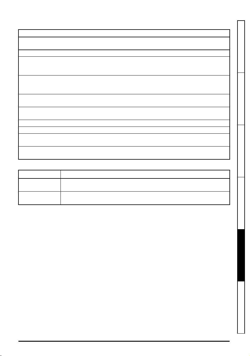
Table 5-5 IP Rating degrees of protection
First digit Second digit
Protection against foreign bodies and access to
hazardous parts
0 Non-protected 0 Non-protected
Protected against solid foreign objects of
1
50 mm ∅ and greater
(back of a hand)
Protected against solid foreign objects of
2
12.5 mm ∅ and greater
(finger)
Protected against solid foreign objects of
3
2.5 mm ∅ and greater (tool)
Protected against solid foreign objects of
4
1.0 mm ∅ and greater (wire)
5 Dust-protected (wire) 5 Protected against water jets
6 Dust-tight (wire) 6 Protected against powerful water jets
7 - 7
8 - 8
Table 5-6 UL enclosure ratings
UL rating Description
Type 1
Type 12
Enclosures are intended for indoor use, primarily to provide a degree of
protection against limited amounts of falling dirt.
Enclosures are intended for indoor use, primarily to provide a degree of
protection against dust, falling dirt and dripping non-corrosive liquids.
Protection against ingress of water
Protected against vertically falling water
1
drops
Protected against vertically falling water
2
drops when enclosure tilted up to 15 °
3 Protected against spraying water
4 Protected against splashing water
Protected against the effects of temporary
immersion in water
Protected against the effects of continuous
immersion in water
Safety information Product information Mechanical installation Electrical installation
5.1.10 Corrosive gasses
Concentrations of corrosive gases must not exceed the levels given in:
• Table A2 of EN 50178:1998
Printed Circuit Board & Component Solder technology of M100-400 are conformal coated to survive
environments as described by IEC60721-3-3 3C3 and EN60068-2-60 Meth. 4. This corresponds to
the levels typical of urban areas with industrial activities and/or heavy traffic and in the immediate
neighborhood of industrial sources with chemical emissions.
5.1.11 RoHS compliance
The drive meets EU directive 2011/65/EU for RoHS compliance.
Unidrive M100 to M400 Frame 1 to 4 Power Installation Guide
Issue Number: 1
81
Technical data
UL listing information
Page 82

5.1.12 Vibration
Bump Test
Testing in each of three mutually perpendicular axes in turn.
Referenced standard: IEC 60068-2-27: Test Ea:
Severity: 15 g peak, 11 ms pulse duration, half sine.
No. of Bumps: 18 (3 in each direction of each axis).
Referenced standard: IEC 60068-2-29: Test Eb:
Severity: 18 g peak, 6 ms pulse duration, half sine.
No. of Bumps: 600 (100 in each direction of each axis).
Random Vibration Test
Testing in each of three mutually perpendicular axes in turn.
Referenced standard: IEC 60068-2-64: Test Fh:
Severity: 1.0 m²/s³ (0.01 g²/Hz) ASD from 5 to 20 Hz
Duration: 30 minutes in each of 3 mutually perpendicular axes.
Sinusoidal Vibration Test
Testing in each of three mutually perpendicular axes in turn.
Referenced standard: IEC 60068-2-6: Test Fc:
Frequency range: 5 to 500 Hz
Severity: 3.5 mm peak displacement from 5 to 9 Hz
Sweep rate:1 octave/minute
Duration: 15 minutes in each of 3 mutually perpendicular axes.
Referenced standard: EN 61800-5-1: 2007, Section 5.2.6.4. referring to IEC 60068-2-6:
Frequency range: 10 to 150 Hz
Severity: 0.075 mm amplitude from 10 to 57 Hz
Sweep rate:1 octave/minute
Duration:10 sweep cycles per axis in each of 3 mutually perpendicular axes.
Testing to Environmental Category ENV3
Subjected to resonance search in the range listed. If no natural frequencies found then subjected
only to endurance test.
Referenced standard: Environment Category ENV3:
Frequency range: 5 to 13.2 Hz ± 1.0 mm
For more information, please refer to section 12
Specification Number 1.
5.1.13 Starts per hour
By electronic control: unlimited
By interrupting the AC supply: ≤20 (equally spaced)
-3 db/octave from 20 to 200 Hz
10 m/s² peak acceleration from 9 to 200 Hz
15 m/s² peak acceleration from 200 to 500 Hz
1g peak acceleration from 57 to 150 Hz
13.2 to 100 Hz ± 0.7g (6.9 ms -2)
Vibration Test 1
of the Lloyds Register Test
5.1.14 Start up time
This is the time taken from the moment of applying power to the drive, to the drive being ready to run
the motor: 1.5 s
82
Unidrive M100 to M400 Frame 1 to 4 Power Installation Guide
Issue Number: 1
Page 83
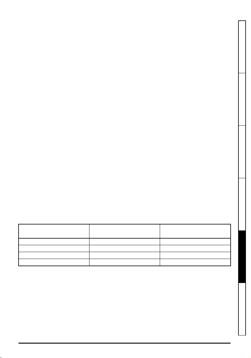
5.1.15 Output frequency / speed range
Unidrive Mxxx models:
In all operating modes (Open loop, RFC-A) the maximum output frequency is limited to 550 Hz.
Unidrive HS30 models:
In open loop mode only, the maximum achievable output frequency is 3,000 Hz.
5.1.16 Accuracy and resolution
Frequency:
The absolute frequency accuracy depends on the accuracy of the oscillator used with the drive
microprocessor. The accuracy of the oscillator is ± 0.02 %, and so the absolute frequency accuracy
is ± 0.02 % of the reference, when a preset frequency is used. If an analog input is used, the absolute
accuracy is further limited by the absolute accuracy of the analog input.
The following data applies to the drive only; it does not include the performance of the source of the
control signals.
Open & closed loop resolution:
Preset frequency reference: 0.01 Hz
Analog input 1: 11 bit plus sign
Analog input 2: 11 bit
Current:
The resolution of the current feedback is 10 bit plus sign.
Accuracy: typical 2 %
worst case 5 %
5.1.17 Acoustic noise
The heatsink fan generates the majority of the sound produced by the drive. The heatsink fan on all
drives is a variable speed fan (except size 1, which is a single speed fan). The drive controls the speed
at which the fan runs based on the temperature of the heatsink and the drive's thermal model system.
Table 5-7 gives the sound pressure level at 1 m produced by the drive for the heatsink fan running at
the maximum and minimum speeds.
Table 5-7 Acoustic noise data
*
Single speed fan.
Size
1* 46.7 N/A
2 45 42
3 58.6 49
4 58 48
Max speed
dBA
Min speed
dBA
Safety information Product information Mechanical installation Electrical installation
Technical data
Unidrive M100 to M400 Frame 1 to 4 Power Installation Guide
Issue Number: 1
UL listing information
83
Page 84
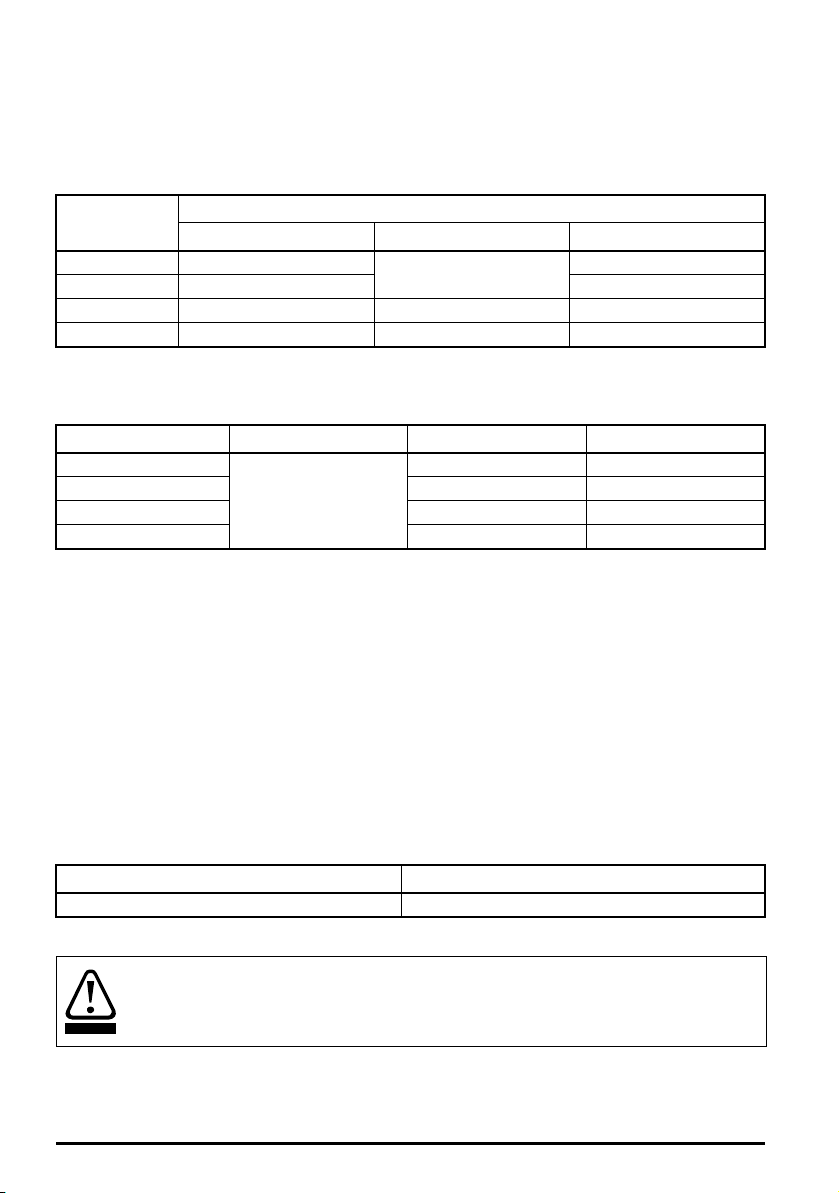
5.1.18 Overall dimensions
WARNING
H Height including surface mounting brackets
W Width
D Projection forward of panel when surface mounted
Table 5-8 Overall drive dimensions
Size
1 160 mm (6.3 in)
2 205 mm (8.07 in) 150 mm (5.9 in)
3 226 mm (8.9 in) 90 mm (3.54 in) 160 mm (6.3 in)
4 277 mm (10.9 in) 115 mm (4.5 in) 175 mm (6.9 in)
H W D
Dimension
75 mm (2.95 in)
130 mm (5.1 in)
5.1.19 Weights
Table 5-9 Overall drive weights
Size Model kg lb
1
2 1.0 2.2
3 1.5 3.3
4 3.13 6.9
All
0.75 1.65
5.1.20 Input current, fuse and cable size ratings
The input current is affected by the supply voltage and impedance.
Typical input current
The values of typical input current are given to aid calculations for power flow and power loss.
The values of typical input current are stated for a balanced supply.
Maximum continuous input current
The values of maximum continuous input current are given to aid the selection of cables and fuses.
These values are stated for the worst case condition with the unusual combination of stiff supply with
bad balance. The value stated for the maximum continuous input current would only be seen in one
of the input phases. The current in the other two phases would be significantly lower.
The values of maximum input current are stated for a supply with a 2 % negative phase-sequence
imbalance and rated at the maximum supply fault current given in Table 5-10.
Table 5-10 Supply fault current used to calculate maximum input currents
Model Symmetrical fault level (kA)
All 10
Fuses
The AC supply to the drive must be installed with suitable protection against overload and
short-circuits. Table 5-11, Table 5-12, Table 5-13 show the recommended fuse ratings.
Failure to observe this requirement will cause risk of fire.
84
Unidrive M100 to M400 Frame 1 to 4 Power Installation Guide
Issue Number: 1
Page 85
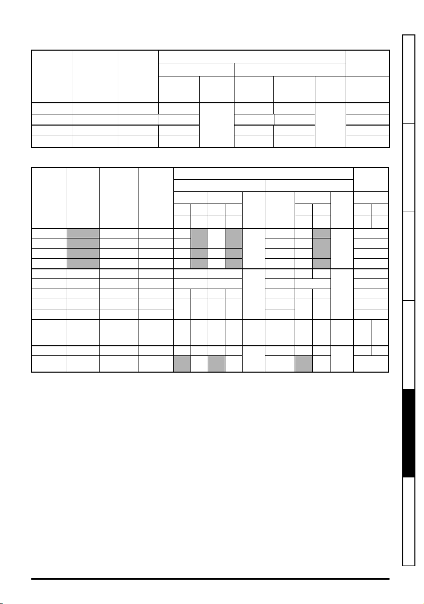
Table 5-11 AC Input current and fuse ratings (100 V)
Class
gG
Fuse rating
Nominal Maximum
15 15
Class
CC, J
or T*
MCB
rating**
Nominal
15
Model
Maximum
continuous
input
current
Maximum
overload
input
current
A A
IEC UL
Maximum
A A A A
01100017 8.7 12.6 10
01100024 11.1 15.2 16 15 15 15
02100042 18.8 28.2 20 20 20 15
02100056 24.0 37.4 25 25 25 15
Table 5-12 AC Input current and fuse ratings (200 V)
Typical
Model
01200017 4.5 6.9 6
01200024 5.3 8.4 6 6 6 15
01200033 8.3 14.2 10 10 15 15 15
01200042 10.4 16.8 16 16 15 15 15
02200024 - / 3.2 5.3/4.1 8.1/5.9 6 6
02200033 - / 4.3 8.3/6.7 14/9.2 10 10 10 10 15
02200042 - / 5.4 10.4/7.5 16.4/10.8 16 10 16 10 15/10 15 10 15
02200056 - / 8.1 16.0/12.9 24.0/17.5
02200075 - / 9.1 18.1/13.5 30.4/19.5 20/15 15
03200100 - / 12.8 23.9 /17.7 30/25 25 20 25 20
04200133 - / 13.5 23.7 /16.9 43.3/23.5 25 20 25 20
04200176 1 7.0 21.3 28.6 25 25 25 25 25
current
Maximum
continuous
input
input
current
A A A A A A A A A A A A
Maximum
overload
input
current
IEC UL / USA
Nominal Maximum
1ph 3ph 1ph 3ph 1ph 3ph 1ph 3ph
6
20 16 20 16
Fuse rating MCB
Maximum
6 6
6 6 6
20/15
20 15
25/20 25 20
25/20 25 20
Class
gG
gG
gG
gG
Nominal
Class
CC, J
or T*
CC,
J or
T*
CC,
J or
T*
CC,
J or
T*
rating
Nominal
15
15
15
25 20
25 20
**
* These are fast acting fuses.
** UL Listed DIVQ / DIVQ7 listed, rated voltage is 600 Vac (for USA and Canada). Short circuit rating
is 10 kA. In other countries, EN IEC circuit breakers can be used with 10 kA supply rating.
Safety information Product information Mechanical installation Electrical installation
Technical data
Unidrive M100 to M400 Frame 1 to 4 Power Installation Guide
Issue Number: 1
UL listing information
85
Page 86

Table 5-13 AC Input current and fuse ratings (400 V)
NOTE
CAUTION
Typical
Model
02400013 2.1 2.4 4.2
02400018 2.6 2.9 5.2
02400023 3.1 3.5 6.1
02400032 4.7 5.1 7.5
02400041 5.8 6.2 9 10 10
03400056 8.3 8.7 13 10 10
03400073 10.2 12.2 18
03400094 13.1 14.8 20.7 25
04400135 14.0 16.3 24.7 20 20
04400170 18.5 20.7 32.4 25 25 25 25 25
current
Maximum
continuous
input
A A A A A A A A
input
current
Maximum
overload
input
current
IEC UL / USA
Nominal Maximum
6 6
16 16
Fuse rating MCB
Nominal Maximum
Class
gG 6 6
15 1 5
gG
20 2 0
gG
Class
CC, J
or T*
CC, J
or T*
CC, J
or T*
rating
Nominal
**
15
15
20
* These are fast acting fuses.
** UL Listed DIVQ / DIVQ7 listed, rated voltage is 600 Vac (for USA and Canada). Short circuit rating
is 10 kA. In other countries, EN IEC circuit breakers can be used with 10 kA supply rating.
Ensure cables used suit local wiring regulations.
The nominal cable sizes below are only a guide. The mounting and grouping of cables
affects their current-carrying capacity, in some cases smaller cables may be acceptable
but in other cases a larger cable is required to avoid excessive temperature or voltage
drop. Refer to local wiring regulations for the correct size of cables.
Table 5-14 Cable ratings (100 V)
Model
Cable size (IEC 60364-5-52)
Input Output Input Output
mm
2
Nominal Maximum Nominal Maximum Nominal Maximum Nominal Maximum
01100017 1
01100024 1.5 1 14
02100042 2.5
02100056 4 1 10
2.5
4
1
1
2.5
4
16
12
Cable size (UL508C)
AWG
12 16 12
10 16 10
86
Unidrive M100 to M400 Frame 1 to 4 Power Installation Guide
Issue Number: 1
Page 87
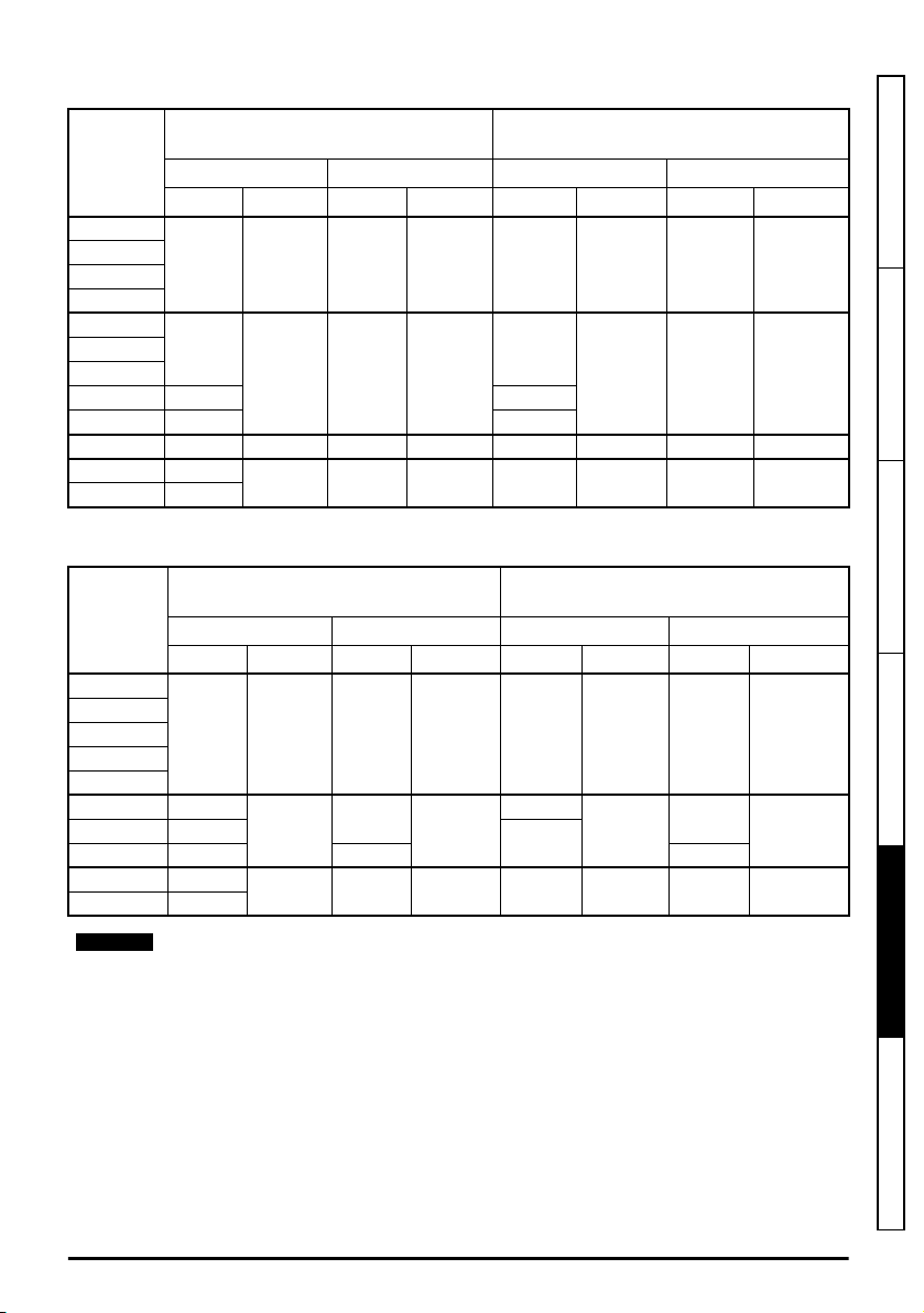
Table 5-15 Cable ratings (200 V)
NOTE
Cable size (IEC 60364-5-52)
Model
01200017
01200024
01200033
01200042
02200024
02200033
02200042
02200056 2.5/1.5 12/14
02200075 2.5 12
03200100 4 4 1.5 4 10/12 10 14 10
04200133 4/2.5
04200176 4
Input Output Input Output
Nominal Maximum Nominal Maximum Nominal Maximum Nominal Maximum
1 2.5 1 2.5 16 12 16 12
1
2
mm
16
4 1 4
4 2.5 4 10 10 12 10
Cable size (UL508C)
AWG
10 16 10
Table 5-16 Cable ratings (400 V)
Cable size (IEC 60364-5-52)
Model
02400013
02400018
02400023
02400032
02400041
03400056 1
03400094 2.5 1.5 14
04400135 2.5
04400170 4
Input Output Input Output
Nominal Maximum Nominal Maximum Nominal Maximum Nominal Maximum
1 4 1 4 16 10 16 10
2
mm
4
4 2.5 4 10 10 12 10
1
4
14
12
Cable size (UL508C)
AWG
10
16
Safety information Product information Mechanical installation Electrical installation
1003400073 1.5
Technical data
PVC insulated cable should be used.
5.1.21 Protective ground cable ratings
Minimum ground conductor size
Either 10 mm2 or two conductors of the same cross-sectional area as the input phase conductor.
Unidrive M100 to M400 Frame 1 to 4 Power Installation Guide
Issue Number: 1
UL listing information
87
Page 88

Table 5-17 Inrush current
Model Peak Inrush Current (A)
01100017 8.5
01100024 8.5
01200017 17
01200024 17
01200033 17
01200042 17
02100042 28.3
02100056 28.3
02200024 27.5
02200033 27.5
02200042 27.5
02200056 27.5
02200075 27.5
02400013 17
02400018 17
02400023 17
02400032 17
02400041 17
03200100 18.3
03400056 11.3
03400073 11.3
03400094 11.3
04200133 18.3
04200176 18.3
04400135 11.3
04400170 11.3
88
Unidrive M100 to M400 Frame 1 to 4 Power Installation Guide
Issue Number: 1
Page 89
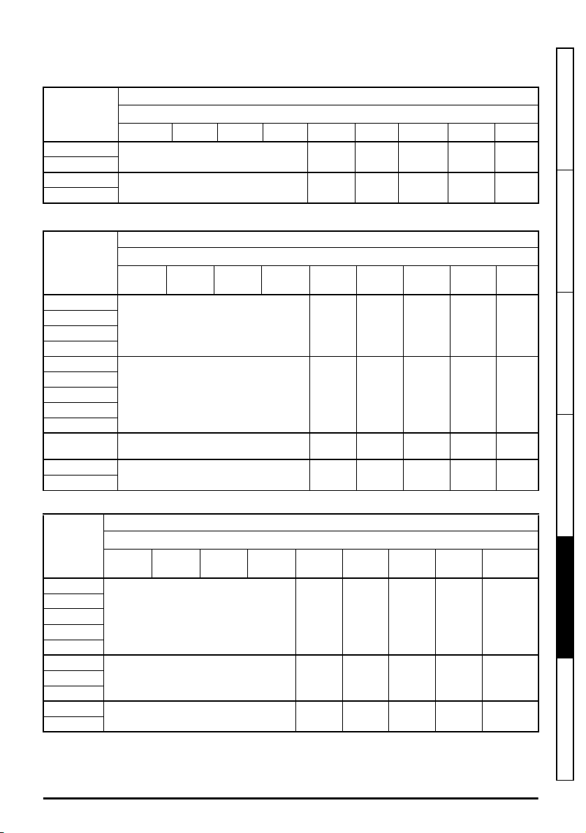
5.1.22 Maximum motor cable lengths
Table 5-18 Maximum motor cable lengths (100 V drives)
100 V Nominal AC supply voltage
Model
01100017
01100024
02100042
02100056
Table 5-19 Maximum motor cable lengths (200 V drives)
Model
01200017
01200024
01200033
01200042
02200024
02200033
02200042
02200056
02200075
03200100 100 m (330 ft)
04200133
04200176
Maximum permissible motor cable length for each of the following switching frequencies
0.667 kHz 1kHz 2 kHz 3 kHz 4 kHz 6 kHz 8 kHz 12 kHz 16 kHz
kHz
37.5 m
(122 ft)
75 m
(245 ft)
3
4
kHz
37.5 m
(122 ft)
75 m
(245 ft)
75 m
(245 ft)
75 m
(245 ft)
75 m (245 ft)
100 m (330 ft)
200 V Nominal AC supply voltage
Maximum permissible motor cable length for each of the following switching frequencies
0.667
kHz
1
kHz
75 m (245 ft)
100 m (330 ft)
100 m (330 ft)
2
kHz
25 m
(82.5 ft)
50 m
(165 ft)
6
kHz
25 m
(82.5 ft)
50 m
(165 ft)
50 m
(165 ft)
50 m
(165 ft)
18.75 m
(61.9 ft)
37.5 m
(122 ft)
8
kHz
18.75 m
(61 ft)
37.5 m
(122 ft)
37.5 m
(122 ft)
37.5 m
(122 ft)
12.5 m
(41.25 ft)
25 m
(82.5 ft)
12
kHz16kHz
12.5 m
(41 ft)
25 m
(82.5 ft)
25 m
(82.5 ft)
25 m
(82.5 ft)
9 m
(29.7 ft)
18 m
(59.4ft)
9 m
(30 ft)
18 m
(60 ft)
18 m
(60 ft)
18 m
(60 ft)
Safety information Product information Mechanical installation Electrical installation
Table 5-20 Maximum motor cable lengths (400 V drives)
400 V Nominal AC supply voltage
Model
02400013
02400018
02400023
02400032
02400041
03400056
03400073
03400094
04400135
04400170
Maximum permissible motor cable length for each of the following switching frequencies
0.667
kHz
1
kHz
100 m (330 ft)
100 m (330 ft)
100 m (330 ft)
kHz
2
3
kHz
4
kHz
75 m
(245 ft)
75 m
(245 ft)
75 m
(245 ft)
6
kHz
50 m
(165 ft)
50 m
(165 ft)
50 m
(165 ft)
8
kHz
37.5 m
(122 ft)
37.5 m
(122 ft)
37.5 m
(122 ft)
12
kHz
25 m
(82.5 ft)
25 m
(82.5 ft)
25 m
(82.5 ft)
16
kHz
18.25 m
(60 ft)
18.25 m
(60 ft)
18.25 m
(60 ft)
• Cable lengths in excess of the specified values may be used only when special techniques are
adopted; refer to the supplier of the drive.
Unidrive M100 to M400 Frame 1 to 4 Power Installation Guide
89
Issue Number: 1
Technical data
UL listing information
Page 90

• The default switching frequency is 3 kHz for Open-loop and RFC-A.
The maximum cable length is reduced from that shown in Table 5-18, Table 5-19 and Table 5-20 if
high capacitance motor cables are used. For further information, refer to section 4.4.2
capacitance / reduced diameter cables
on page 53.
High-
5.1.23 Minimum resistance values and peak power rating for the braking resistor
at 40 °C (104 °F)
Table 5-21 Braking resistor resistance and power rating (100 V)
Model
01100017
01100024 0.37
02100042
02100056 1.1
Table 5-22 Braking resistor resistance and power rating (200 V)
Model
01200017
01200024 0.37
01200033 0.55
01200042 0.75
02200024
02200033 0.55
02200042 0.75
02200056 1.1
02200075 1.5
03200100 45 3.3 2.2
04200133
04200176 4
Minimum
resistance*
Ω
130 1.1
68 2.2
Minimum
resistance*
Ω
130 1.1
68 2.2
22 6.0
Instantaneous
power rating
kW
Instantaneous
power rating
kW
Continuous
power rating
kW
0.25
0.75
Continuous
power rating
kW
0.25
0.37
3
90
Unidrive M100 to M400 Frame 1 to 4 Power Installation Guide
Issue Number: 1
Page 91
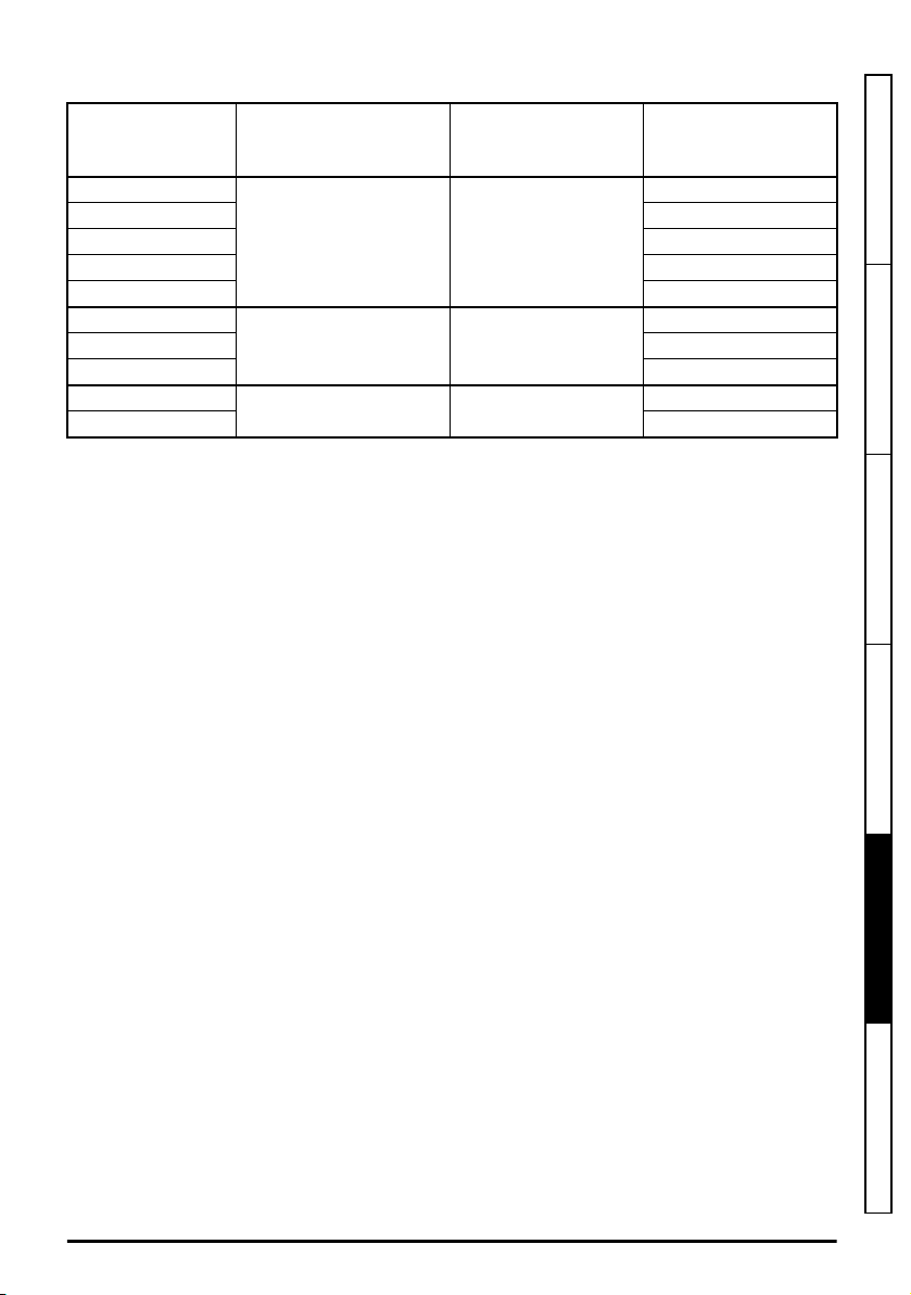
Table 5-23 Braking resistor resistance and power rating (400 V)
Minimum
Model
02400013
02400018 0.55
02400023 0.75
02400032 1.1
02400041 1.5
03400056
03400073 3
03400094 4
04400135
04400170 7.5
* Resistor tolerance: ±10 %
For high-inertia loads or under continuous braking, the
resistor may be as high as the power rating of the drive. The total
resistor is dependent on the amount of energy to be extracted from the load.
The instantaneous power rating refers to the short-term maximum power dissipated during the on
intervals of the pulse width modulated braking control cycle. The braking resistor must be able to
withstand this dissipation for short intervals (milliseconds). Higher resistance values require
proportionately lower instantaneous power ratings.
In most applications, braking occurs only occasionally. This allows the continuous power rating of the
braking resistor to be much lower than the power rating of the drive. It is therefore essential that the
instantaneous power rating and energy rating of the braking resistor are sufficient for the most
extreme braking duty that is likely to be encountered.
Optimization of the braking resistor requires careful consideration of the braking duty.
Select a value of resistance for the braking resistor that is not less than the specified minimum
resistance. Larger resistance values may give a cost saving, as well as a safety benefit in the event
of a fault in the braking system. Braking capability will then be reduced, which could cause the drive
to trip during braking if the value chosen is too large.
resistance*
Ω
270 2.2
100 6.0
50 11.2
Instantaneous
power rating
kW
continuous power
energy
Continuous
power rating
kW
0.37
2.2
5.5
dissipated in the braking
dissipated in the braking
Safety information Product information Mechanical installation Electrical installation
Unidrive M100 to M400 Frame 1 to 4 Power Installation Guide
Issue Number: 1
Technical data
UL listing information
91
Page 92

5.1.24 Terminal sizes and torque settings
WARNING
To avoid a fire hazard and maintain validity of the UL listing, adhere to the specified
tightening torques for the power and ground terminals. Refer to the following tables.
Table 5-24 Drive control terminal data
Model Connection type Torque setting
All Screw terminals 0.2 N m (0.15 lb ft)
Table 5-25 Drive relay terminal data
Model Connection type Torque setting
All Screw terminals 0.5 N m (0.4 lb ft)
Table 5-26 Drive power terminal data
Model
size
1
2
3
4
Table 5-27 Terminal block maximum cable sizes
Model size Terminal block description Max cable size
AC and motor terminals DC and braking Ground terminal
Recommended Maximum Recommended Maximum Recommended Maximum
0.5 N m
(0.4 lb ft)
1.4 N m
(1 lb ft)
All Control connector
All 2-way relay connector
1 to 4 STO connector
1 AC input / output power connector
2 to 4 AC input / output power connector
0.5 N m
(0.4 lb ft)
1.4 N m
(1 lb ft)
1.5 N m
(1.1 lb ft)
1.5 mm2 (16 AWG)
2.5 mm2 (12 AWG)
0.5 mm2 (20 AWG)
2.5 mm2 (12 AWG)
4.0 mm2 (10 AWG)
92
Unidrive M100 to M400 Frame 1 to 4 Power Installation Guide
Issue Number: 1
Page 93

5.1.25 Electromagnetic compatibility (EMC)
This is a summary of the EMC performance of the drive. For full details, refer to the EMC Data Sheet
which can be obtained from the supplier of the drive.
Table 5-28 Immunity compliance
Standard
IEC 61000-4-2
EN61000-4-2:2009
IEC 61000-4-3
EN61000-4-3:2006+A2:2010
IEC61000-4-4
EN61000-4-4:2012
IEC61000-4-5
EN61000-4-5:2014
IEC61000-4-6
EN61000-4-6:2014
IEC61000-4-11
EN61000-4-11:2004
IEC61000-6-1
EN61000-6-1:2007
IEC61000-6-2
EN61000-6-2:2005
IEC61800-3
EN 61800-3: 2004+A1:2012
*
See section 4.7.6
Variations in the EMC wiring
Type of
immunity
Electrostatic
discharge
Radio frequency
radiated field
Fast transient
burst
Surges
Conducted radio
frequency
Voltage dips and
interruptions
Generic immunity standard for the
residential, commercial and light - industrial
environment
Generic immunity standard for the industrial
environment
Product standard for adjustable speed power
drive systems (immunity requirements)
Test specification Application Level
6 kV contact discharge
8 kV air discharge
10 V/m prior to
modulation
80 - 1000 MHz
80 % AM (1 kHz)
modulation
5/50 ns 2 kV transient at
5 kHz repetition
frequency via coupling
clamp
5/50 ns 2 kV transient at
5 kHz repetition
frequency by direct
injection
Common mode 4 kV
1.2/50 µs waveshape
Differential mode
2 kV1.2/50 µs waveshape
Lines to ground
10V prior to modulation
0.15 - 80 MHz
80 % AM (1 kHz)
modulation
-30 % 10 ms
+60 % 100 ms
-60 % 1 s
<-95 % 5 s
on page 72 for control ports for possible
Module enclosure
Module enclosure
Control lines
Power lines
AC supply lines:
line to ground
AC supply lines:
line to line
Signal ports to
ground
*
Control and power
lines
AC power ports
Meets immunity requirements for first
and second environments
Level 3
(industrial)
Level 3
(industrial)
Level 4
(industrial harsh)
Level 3
(industrial)
Level 4
Level 3
Level 2
Level 3
(industrial)
Complies
Complies
requirements regarding grounding and external surge protection.
Emission
The drive contains an in-built filter for basic emission control. An additional optional external filter
provides further reduction of emission. The requirements of the following standards are met,
depending on the motor cable length and switching frequency.
Safety information Product information Mechanical installation Electrical installation
Technical data
UL listing information
Unidrive M100 to M400 Frame 1 to 4 Power Installation Guide
Issue Number: 1
93
Page 94

Table 5-29 Size 1 emission compliance
Motor cable
length
(m)
Using internal filter only:
2 C3 C3 C3 C3 C3 C3 C3 C3 C3
10 C3 C3 C3 C3 C4 C4 C4 C4 C4
Using external filter and internal filter:
2 C1 C1 C1 C1 C1 C1 C1 C1 C1
20 C1 C1 C1 C1 C2 C2 C2 C2 C2
50 C2 C2 C2 C2 - -
Using low leakage external filter:
10 C1 C1 C1 C1 - -
Table 5-30 Size 2 emission compliance
Motor cable
length
(m)
Using internal filter only:
2 C3 C3 C3 C3 C3 C4 C4 C4 C4
10 C4 C4 C4 C4 C4 C4 C4 C4 C4
Using external filter and internal filter:
2 C1 C1 C1 C1 C1 C1 C1 C1 C1
20 C1 C1 C1 C1 C2 C2 C2 C2 C2
100 C2 C2 C2 C2 - - - - -
Using low leakage external filter:
10 C1 C1 C1 C1 - - - - -
Table 5-31 Size 3 emission compliance
Motor cable
length
(m)
Using internal filter only:
2 C3 C3 C3 C3 C3 C3 C4 C4 C4
10 C4 C4 C4 C4 C4 C4 C4 C4 C4
Using external filter and internal filter:
2 C1 C1 C1 C1 C1 C1 C1 C1 C1
20 C1 C1 C1 C1 C2 C2 C2 C2 C2
100 C2 C2 C2 C2 - - - - -
Using low leakage external filter:
10 C1 C1 C1 C1 - - - - -
0.667 1 2 3 4 6 8 12 16
0.667 1 2 3 4 6 8 12 16
0.667 1 2 3 4 6 8 12 16
Switching Frequency (kHz)
- - -
- - -
Switching Frequency (kHz)
Switching Frequency (kHz)
94
Unidrive M100 to M400 Frame 1 to 4 Power Installation Guide
Issue Number: 1
Page 95

Table 5-32 Size 4 emission compliance
CAUTION
Motor cable
length
(m)
0.667 1 2 3 4 6 8 12 16
Switching Frequency (kHz)
Using internal filter only:
2 C3 C3 C3 C3 C3 C3 C4 C4 C4
5 C3 C3 C3 C3 C3 C3 C3 C3 C4
10 C3 C3 C3 C3 C3 C3 C4 C4 C4
Using external filter and internal filter:
2 C1 C1 C1 C1 C1 C1 C1 C1 C1
20 C1 C1 C1 C1 C2 C2 C2 C2 C2
100 C2 C2 C2 C2 - - - - -
Using low leakage external filter:
10 C1 C1 C1 C1 - - - - -
This is a product of the restricted distribution class according to IEC 61800-3. In a
residential environment this product may cause radio interference in which case the user
may be required to take adequate measures.
Residential generic standard EN 61000-6-3:2007+A1:2011
EN 61800-3:2004+A1:2012 first environment unrestricted distribution
EN 61800-3:2004+A1:2012 defines the following:
• The first environment is one that includes residential premises. It also includes establishments
directly connected without intermediate transformers to a low-voltage power supply network
which supplies buildings used for residential purposes. The second environment is one that
includes all establishments other than those directly connected to a low-voltage power supply
network which supplies buildings used for residential purposes.
• Restricted distribution is defined as a mode of sales distribution in which the manufacturer
restricts the supply of equipment to suppliers, customers or users who separately or jointly have
technical competence in the EMC requirements of the application of drives.
IEC 61800-3:2004 and EN 61800-3:2004+A1:2012
The 2004 revision of the standard uses different terminology to align the requirements of the
standard better with the EC EMC Directive.
Power drive systems are categorized C1 to C4:
Safety information Product information Mechanical installation Electrical installation
Technical data
Category Definition
C1 Intended for use in the first or second environments R
Not a plug-in or movable device, and intended for use in the first
C2
environment only when installed by a professional, or in the
second environment
C3
C4
Intended for use in the second environment, not the first
environment
Rated at over 1000 V or over 400 A, intended for use in complex
systems in the second environment
Unidrive M100 to M400 Frame 1 to 4 Power Installation Guide
Issue Number: 1
Corresponding
code used
previously
UL listing information
I
E2U
E2R
95
Page 96

5.2 Optional external EMC filters
Table 5-33 Drive and EMC filter cross reference
Model CT part number
100 V
01100017 to 01100024 4200-1000, 4200-1001 (low leakage)
02100042 to 02100056 4200-2000
200 V
01200017 to 01200042 4200-1000, 4200-1001 (low leakage)
02200024 to 02200075
03200100
04200133 to 04200176
400 V
02400013 to 02400041 4200-2005, 4200-2006 (low leakage)
03400056 to 03400094 4200-3008, 4200-3009 (low leakage)
04400135 to 04400170 4200-4004, 4200-4005 (low leakage)
4200-2001, 4200-2002 (low leakage)
4200-2003, 4200-2004 (low leakage)
4200-3000, 4200-3001 (low leakage)
4200-3004, 4200-3005 (low leakage)
4200-4000, 4200-4001 (low leakage)
4200-4002, 4200-4003 (low leakage)
96
Unidrive M100 to M400 Frame 1 to 4 Power Installation Guide
Issue Number: 1
Page 97
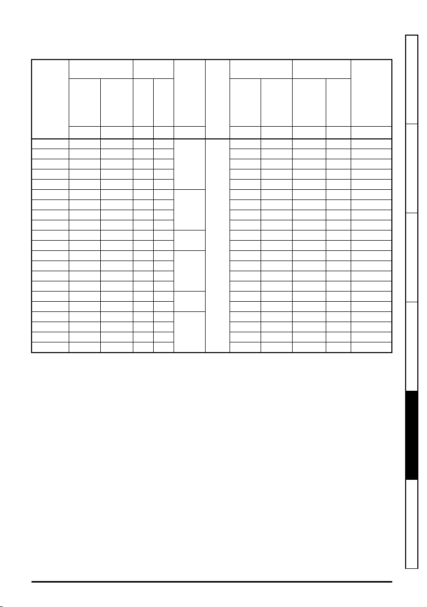
5.2.1 EMC filter ratings
Table 5-34 Optional external EMC filter details
Maximum
continuous curr ent
CT part
number
4200-1000 11 9.7 250 250
4200-1001 11 9.7 250 250 6.7 5.2 2.38 5.82
4200-2000 25 22 110 250 12.1 9.4 11.7 20.8
4200-2001 18 15.8 250 250 7.5 5.8 2 4.6 43.5
4200-2002 18 15.8 250 250 7.5 5.8 2 .38 5.82
4200-2003 13 11.4 250 250
4200-2004 13 11.4 250 250 10.7 8.3 1.84 43.4
4200-2005 6 5.3 480 480 4 3.1 3.6 77.5
4200-2006 6 5.3 480 480 4 3.1 1.2 30.5
4200-3000 23 20.2 250 250
4200-3001 23 20.2 250 250 11.1 8.6 3.4 8.3
4200-3004 17 15 250 250
4200-3005 17 15 250 250 11.7 9.1 0.7 1 6
4200-3008 14 12.3 480 480 8.8 6.8 3.6 7 7.5
4200-3009 14 12.3 480 480 8.8 6.8 1 .32 33.2
4200-4000 24 21.1 250 250
4200-4001 24 21.1 250 250 13.8 10.7 3.4 8.3
4200-4002 20 17.6 250 250
4200-4003 20 17.6 250 250 13.8 10.7 0.7 16
4200-4004 17 15 480 480 14.3 11.1 3.6 77.5
4200-4005 17 15 480 480 14.3 11.1 1.3 33.2
@ 40 °C
(104 °F)
@ 50 °C
(122 °F)
A A V V ph W
Voltage
rating
IEC UL
Phases
1
3
1
3
1
3
Power dissipation
at rated current
IP
rating
20
@ 40 °C
(104 °F)
@ 50 °C
(122 °F )
W mA mA
6 4.7 24.6 43.5
10.7 8.3 1.84 43.4
11.1 8.6 24 43
11.7 9.1 0.7 16
13.8 10.7 24 43
13.8 10.7 0.7 16
Ground leakage
Balanced
supply
phase-to-
phase &
phase-to-
ground
Worst
case
Discharge
resistors
M
Ω
Safety information Product information Mechanical installation Electrical installation
Unidrive M100 to M400 Frame 1 to 4 Power Installation Guide
Issue Number: 1
Technical data
UL listing information
97
Page 98

5.2.2 Overall EMC filter dimensions
Table 5-35 Optional external EMC filter dimensions
CT part
number
4200-1000 215 8.46 75 2.95 41 1.61 0.49 1.08
4200-1001 215 8.46 75 2.95 41 1.61 0.49 1.08
4200-2000 261 10.28 78 3.07 41 1.61 0.90 1.98
4200-2001 261 10.28 78 3.07 41 1.61 0.86 1.89
4200-2002 261 10.28 78 3.07 41 1.61 0.86 1.89
4200-2003 261 10.28 78 3.07 41 1.61 0.88 1.94
4200-2004 261 10.28 78 3.07 41 1.61 0.88 1.94
4200-2005 261 10.28 78 3.07 41 1.61 0.82 1.80
4200-2006 261 10.28 78 3.07 41 1.61 0.82 1.80
4200-3000 282 11.10 90 3.54 41 1.61 0.92 2.02
4200-3001 282 11.10 90 3.54 41 1.61 0.92 2.02
4200-3004 282 11.10 90 3.54 41 1.61 0.95 2.09
4200-3005 282 11.10 90 3.54 41 1.61 0.95 2.09
4200-3008 282 11.10 90 3.54 41 1.61 1 2.20
4200-3009 282 11.10 90 3.54 41 1.61 1 2.20
4200-4000 334 13.15 115 4.53 41 1.61 1.3 2.86
4200-4001 334 13.15 115 4.53 41 1.61 1.3 2.86
4200-4002 334 13.15 115 4.53 41 1.61 1.4 3.08
4200-4003 334 13.15 115 4.53 41 1.61 1.4 3.08
4200-4004 334 13.15 115 4.53 41 1.61 1.4 3.08
4200-4005 334 13.15 115 4.53 41 1.61 1.4 3.08
H W D
mm inch mm inch mm inch kg
Dimension (mm)
Weight
lb
98
Unidrive M100 to M400 Frame 1 to 4 Power Installation Guide
Issue Number: 1
Page 99

6
UL listing information
6.1 UL file reference
All products covered by this Guide are UL Listed to both Canadian and US requirements. The UL file
reference is: NMMS/7.E171230.
Products that incorporate the Safe Torque Off function have been investigated by UL. The UL file
reference is: FSPC.E171230.
6.2 Option modules, kits and accessories
All Option Modules, Control Pods and Installation Kits supplied by Emerson Industrial Automation for
use with these drives are UL Listed.
6.3 Enclosure ratings
Drives are UL Open Type as supplied.
Drives fitted with a conduit box are UL Type 1.
Remote Keypads are UL Type 12.
6.4 Mounting
Drives can be mounted directly onto a vertical surface. This is known as 'surface' or 'standard'
mounting. Refer to section 3.4 Drive dimensions and mounting methods on page 21 for further
information.
Drives can be installed side by side with recommended spacing between them. This is known as
'bookcase' mounting. Refer to section 3.5 Enclosure layout on page 23 for further information.
Drives fitted with a conduit box can be mounted directly onto a wall or other vertical surface without
additional protection. Suitable conduit boxes are available from Emerson Industrial Automation.
Remote Keypads can be mounted on the outside of a UL Type 12 enclosure. A sealing and mounting
kit is provided with the keypad.
Safety information Product information Mechanical installation Electrical installation Technical data
6.5 Environment
Drives must be installed in a Pollution Degree 2 environment or better (dry, non-conductive pollution
only). All drives are capable of delivering full rated output current at surrounding air temperatures up
to 40 °C
Drives may be operated in surrounding air temperatures up to 50 °C or 55 °C at de-rated current,
depending on the model number. Refer to Chapter 5 Technical data on page 75 for further
information.
Unidrive M100 to M400 Frame 1 to 4 Power Installation Guide
Issue Number: 1
99
UL listing information
Page 100

6.6 Electrical Installation
TERMINAL TORQUE
Terminals must be tightened to the rated torque as specified in the Installation Instructions. Refer to
section 3.8.1 Terminal sizes and torque settings on page 34 for further information.
WIRING TERMINALS
Drives must be installed using cables rated for 75 °C operation, copper wire only.
UL Listed closed-loop connectors sized according to the field wiring shall be used for all field wiring
connections. Refer to section 4.1.2 Ground connections on page 42 for further information.
BRANCH CIRCUIT PROTECTION
The fuses and circuit breakers required for branch circuit protection are contained in the Installation
Instructions. Refer to section 4.3 Ratings on page 47 for further information.
OPENING OF BRANCH CIRCUIT
Opening of the branch-circuit protective device may be an indication that a fault has been
interrupted. To reduce the risk of fire or electric shock, the equipment should be examined and
replaced if damaged. If burnout of the current element of an overload relay occurs, the complete
overload relay must be replaced.
Integral solid state short circuit protection does not provide branch circuit protection. Branch circuit
protection must be provided in accordance with the National Electrical Code and any additional local
"codes".
DYNAMIC BRAKING
Drives with model numbers beginning M100, M101, M200, M201, M300 or M400 have been
evaluated for dynamic braking applications.
6.7 Motor overload protection and thermal memory retention
All drives incorporate internal overload protection for the motor load that does not require the use of
an external or remote overload protection device.
The protection level is adjustable and the method of adjustment is provided in the Control User
Guide. Maximum current overload is dependent on the values entered into the current limit
parameters (motoring current limit, regenerative current limit and symmetrical current limit entered as
percentage) and the motor rated current parameter (entered in amperes).
The duration of the overload is dependent on motor thermal time constant. The time constant is
programmable. The default overload protection is typically set to 150 % of the motor rated current for
120 seconds.
The drives are provided with user terminals that can be connected to a motor thermistor to protect
the motor from high temperature, in the event of a motor cooling fan failure.
The method of adjustment of the overload protection is provided in the Installation Instructions
shipped with the product.
All models are provided with thermal memory retention.
100
Unidrive M100 to M400 Frame 1 to 4 Power Installation Guide
Issue Number: 1
 Loading...