

Page 1

SCADAPack 32P Controller
Hardware Manual
CONTROL
MICROSYSTEMS
SCADA products... for the distance
48 Steacie Drive Telephone: 613-591-1943
Kanata, Ontario Facsimile: 613-591-1022
K2K 2A9 Technical Support: 888-226-6876
Canada 888-2CONTROL
Page 2

SCADAPack 32P Controller Hardware Manual
©2000 - 2006 Control Microsystems Inc.
All rights reserved.
Printed in Canada.
Trademarks
TeleSAFE, TelePACE, SmartWIRE, SCADAPack, TeleSAFE Micro16 and
TeleBUS are registered trademarks of Control Microsystems Inc.
All other product names are copyright and registered trademarks or trade names
of their respective owners.
Material used in the User and Reference manual section titled SCADAServer
OLE Automation Reference is distributed under license from the OPC
Foundation.
SCADAPack 32P Controller Hardware Manual
May 26, 2006
1
Page 3

Table of Contents
1 OVERVIEW.................................................................................................... 5
2 IMPORTANT SAFETY INFORMATION ........................................................ 6
3 INSTALLATION............................................................................................. 7
3.1 Field Wiring Connections ............................................................................... 7
3.1.1 5232 Controller Board Field Wiring Connectors........................................7
3.2 Power Supply.................................................................................................8
3.2.1 Controller Board Power Supply.................................................................8
3.2.2 Power Supply Input Connections.............................................................. 8
3.2.3 Recommended AC Power Supply Configuration...................................... 9
3.2.4 Recommended DC Power Supply Configuration...................................... 9
3.2.5 Recommended 24VDC Battery Supply Configuration ............................ 10
3.2.6 Recommended 5103 Power Supply Configuration................................. 10
3.2.7 System Grounding.................................................................................. 11
3.3 Internal Analog Inputs..................................................................................11
3.4 Digital /Counter Inputs.................................................................................. 12
3.5 Interrupt Input............................................................................................... 13
3.6 Status Output............................................................................................... 13
4 SERIAL COMMUNICATION ........................................................................ 15
4.1 RS-232 Serial Communications Ports.......................................................... 15
4.1.1 COM1 RS-232 Serial Port.......................................................................15
4.1.2 COM2 RS-232 Serial Port.......................................................................16
4.1.3 COM4 RS-232 Serial Port.......................................................................16
4.1.4 RJ-45 Modular Connector for RS-232....................................................17
4.2 RS-232 Wiring Examples............................................................................. 18
4.2.1 DTE to DTE without Handshaking.......................................................... 18
4.2.2 DTE to DTE with Handshaking............................................................... 19
4.2.3 DTE to DCE with Handshaking............................................................... 19
4.3 RS-232 Cables............................................................................................. 20
4.3.1 RJ-45 to DE-9S DTE.............................................................................. 20
4.3.2 RJ-45 to DE-9P DCE.............................................................................. 20
4.4 RS-485 Serial Communication Port ............................................................. 20
SCADAPack 32P Controller Hardware Manual
May 26, 2006
2
Page 4

4.4.1 RJ-45 Modular Connector for RS-485....................................................21
4.4.2 RS-485 Bias Resistors............................................................................21
4.4.3 RS-485 Termination Resistors................................................................ 22
4.5 RS-485 Wiring Examples............................................................................. 22
4.5.1 Four wire mode....................................................................................... 22
4.5.2 Two wire mode.......................................................................................23
4.6 RS-485 Cable............................................................................................... 24
5 ETHERNET COMMUNICATION.................................................................. 26
5.1 LAN Port Settings......................................................................................... 26
5.1.1 TCP/IP Settings...................................................................................... 26
5.1.2 Modbus/TCP Settings............................................................................. 26
5.1.3 RJ-45 Modular Connector for Ethernet................................................... 27
6 OPERATION................................................................................................ 29
6.1 Run Mode .................................................................................................... 29
6.2 Service Mode............................................................................................... 29
6.3 Cold Boot Mode ........................................................................................... 30
6.4 SCADAPack 32P LED Indicators................................................................. 30
6.5 LED Power Control ...................................................................................... 31
6.6 Status LED and Output................................................................................31
6.6.1 I/O Module Error Indication..................................................................... 32
6.6.2 Register Assignment Checksum Error.................................................... 32
6.6.3 Too Many I/O Operations Requested Error............................................ 32
6.7 Configuration Switches ................................................................................ 33
6.7.1 Digital Input Filters.................................................................................. 33
6.7.2 Line Frequency Selection.......................................................................34
7 MAINTENANCE........................................................................................... 35
7.1 Fuses...........................................................................................................35
7.2 Lithium Battery............................................................................................. 35
7.2.1 Battery Replacement Procedure............................................................. 35
8 SPECIFICATIONS....................................................................................... 37
8.1 General........................................................................................................37
8.2 SCADAPack 32P Controller......................................................................... 37
SCADAPack 32P Controller Hardware Manual
May 26, 2006
3
Page 5

8.3 Communications .......................................................................................... 37
8.4 Visual Indicators........................................................................................... 38
8.5 Power Supply...............................................................................................38
8.6 I/O Capacity ................................................................................................. 39
8.7 Digital Inputs ................................................................................................ 39
8.8 Digital Outputs.............................................................................................. 39
8.9 Approvals and Certifications......................................................................... 39
Index of Figures
Figure 1: SCADAPack 32P..................................................................................................5
Figure 2: 5232 Controller Module ........................................................................................8
SCADAPack 32P Controller Hardware Manual
May 26, 2006
4
Page 6
1 Overview
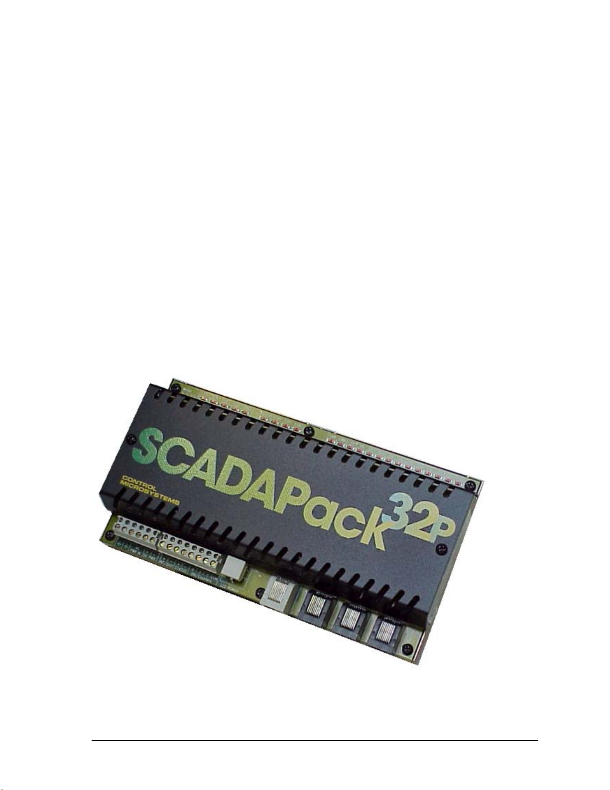
The SCADAPack 32P consists of a 5232 Controller board, see Figure 1: SCADAPack 32P.
Application programs for the controller can be written in either TelePACE Ladder Logic, or
optionally IEC61131, and C/C++ language.
The 5232 Controller provides an integrated power supply, three digital/counter inputs, an interrupt
input and a status output. The 10-BaseT Ethernet port and three serial communication ports enable
connection to a large variety of communication networks. Two of the serial communication ports are
RS-232 and the third is configurable for RS-232 or RS-485.
The RS-232 serial communication ports on the controller board support half-duplex and full-duplex
communication. They support RTS/CTS hardware handshaking for connection to modems and radio
modems. The RS-232 and RS-485 ports operate at baud rates from 300 baud to 38400 baud.
Using 5000 Series I/O modules can expand the I/O capacity of SCADAPack 32P Controllers. A
maximum of forty 5000 Series I/O modules may be connected for an expansion of up to 512 digital
outputs, 512 digital inputs, 128 analog inputs, 32 counters and 32 analog outputs.
The 5232 Controller memory has 8 Mbytes SDRAM, 4 Mbytes flash ROM, and 1 Mbyte CMOS
SRAM. The CMOS SRAM is non-volatile (battery backed.). A real time clock calendar provides for
time of day operations and alarms. A hardware watchdog timer protects against application program
failures.
Low power applications also benefit from the SCADAPack 32P ability to enable and disable status
LED’s on all modules connected to the 5000 Series I/O bus including the controller board.
Figure 1: SCADAPack 32P
SCADAPack 32P Controller Hardware Manual
May 26, 2006
5
Page 7
2 Important Safety Information
Power, input and output (i/o) wiring must be in accordance with Class I, Division 2 wiring methods
Article 501-4 (b) of the National Electrical Code, NFPA 70 for installations in the U.S., or as
specified in Section 18-1J2 of the Canadian Electrical Code for installations within Canada and in
accordance with the authority having jurisdiction.
WARNING !
EXPLOSION HAZARD - SUBSTITUTION OF COMPONENTS M AY
IMPAIR SUITABILITY FOR CLASS 1, DI V I S I ON 2 .
WARNING !
EXPLOSION HAZARD – WHEN IN HAZARDOUS LOCATIONS, TURN
OFF POWER BEFORE REPLACING OR WIRING MODULES.
WARNING !
EXPLOSION HAZARD - DO NOT DISCONNECT EQUIPMENT
UNLESS POWER HAS BEEN SWITCHED OFF OR THE AREA IS
KNOWN TO BE NONHAZA RDOUS.
SCADAPack 32P Controller Hardware Manual
May 26, 2006
6
Page 8

3 Installation
The installation of SCADAPack 32P controllers requires mounting the SCADAPack 32P controller
on the 7.5mm by 35mm DIN rail and connecting the SCADAPack controller to the system I/O Bus.
Refer to the System Configuration Guide for complete information on system layout, I/O Bus cable
routing and SCADAPack 32P controller installation.
3.1 Field Wiring Connections
SCADAPack 32P controllers use screw termination style connectors for termination of field wiring.
These connectors can accommodate solid or stranded wires from 22 to 12 AWG.
The termination connectors fit over pins on the 5232 controller board. The connectors are removable
allowing replacement of the SCADAPack 32P Controller without disturbing the field wiring. Leave
enough slack in the field wiring for the connector to be removed.
CAUTION: Remove power before servicing unit.
To remove the termination connector:
• Pull the connector upward from the board. Apply even pressure to both ends of the connector.
To install the termination connector:
• Line up the pins on the module with the holes in the connector. Make sure all the pins line up
properly.
• Push the connector onto the pins. Apply even pressure to both ends of the connector.
3.1.1 5232 Controller Board Field Wiring Connectors
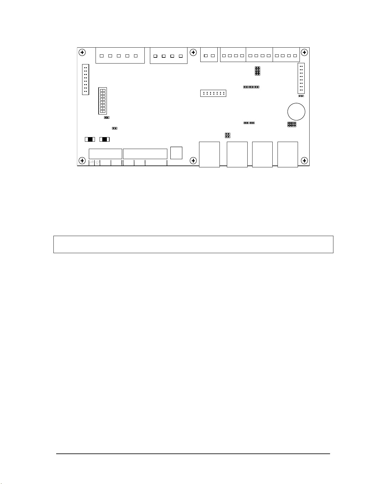
The 5232 Controller board has six termination connectors for the connection of field wiring. Refer to
the diagram Figure 2: 5232 Controller Module for field wiring connector locations.
Primary power input connections; output power connection and ground connections are wired to a
six-pole connector labeled P3. Refer to section 3.2.1-Controller Board Power Supply for more
information on these connections.
The three digital/counter inputs (DIN/Counters), interrupt input/counter (INT/Cntr) and status output
(STATUS) are wired to an eight-pole connector labeled P4. Refer to section 3.4-Digital /Counter
Inputs, 3.5-Interrupt Input and 3.6-Status Output for more information on these connections.
Each of the three serial communication ports is wired to black 8 pin modular RJ-45 connectors.
COM1 connector is labeled P6, COM2 connector is labeled P7, and COM4 connector is labeled P8.
Refer to section 4-Serial Communication for more information on serial communication
connections.
The Ethernet LAN Port is wired to a gray 8 pin modular RJ-45connector labeled P5. Refer to section
5-Ethernet Communication for more information on Ethernet connections.
SCADAPack 32P Controller Hardware Manual
May 26, 2006
7
Page 9
R
T
T
K
S
X
X
P1
5V LEDSSTA
RUN
Power Supply and CPU
FORCE
IN
CTR1 CTR2CTR0
Interupt and Counters
TX
DCD
CTS
RX
TX
LIN
LAN
LAN COM2
COM1
P11
DCD
CTS
R
T
DCD
CT
RX
COM4
P2
SW 1
J5
J3
F2
F1
0 1 2 COM
DIN/COUNTER
P4
LED POWER
P3
+ –
+ –
DC PW
+ –
INT
STA T U S
AC/DC
PWR
IN
LAN
P9
RS485
J7
J8
P5
RS-232/485
TX
RX
COM1
P6
J2
J9 J10
RS232
P7
COM2
RS-232
P11
COM Port
P8
COM4
RS-232
J4
BT1
Figure 2: 5232 Controller Module
3.2 Power Supply
The SCADAPack 32P controller is primarily a DC input powered device but can be powered with
16Vac under some conditions. The power supply requirements for the 5232 Controller board are
each explained in the following sections.
NOTE: Voltages referred to as Vrms (or Vac) indicate AC power. Voltages referred to as V (or
Vdc) indicate DC power.
3.2.1 Controller Board Power Supply
The 5232 Controller board can be powered from a 12Vdc to 24Vdc power source applied to the DC
PWR input or a 16Vac power source applied to the AC PWR IN input. With input power applied the
5232 Controller board power supply provides an internal 5V output to power 5000 Series modules
through the inter module cable (IMC).
The 5V supply has a 1.3A output capacity of which 500mA is required by the 5232 Controller board.
The remaining capacity, 800mA, is used to power 5000 Series modules connected through the IMC
cable.
When the 5232 Controller board is powered with 16Vac power applied to the AC PWR IN input a
limited amount of 24Vdc power is provided on the DC PWR terminals. The amount of 24Vdc power
available is dependent on the amount of 5V output power used in the system. With a 5Vdc output
power of 500mA there is 300mA is available and this value is derated linearly to 100mA with a
5Vdc output power of 1.3A.
3.2.2 Power Supply Input Connections
Input power is connected to the SCADAPack 32P controller in one of the following ways:
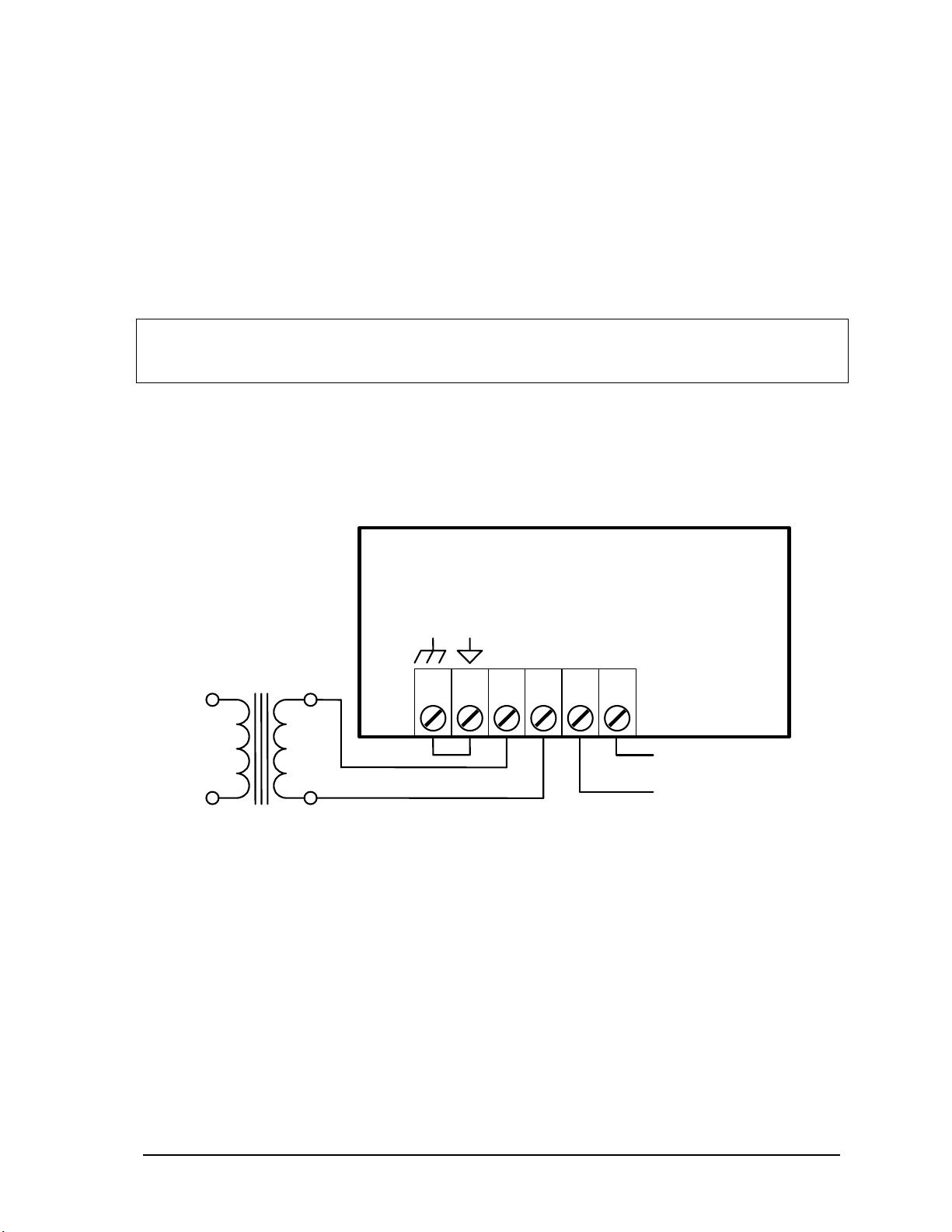
• A 16Vac source connects to the AC PWR IN terminals on the 5232 Controller board. See section
3.2.3-Recommended AC Power Supply Configuration for an example of using a 16Vac
transformer to power the SCADAPack 32P controller.
SCADAPack 32P Controller Hardware Manual
8
May 26, 2006
Page 10
• An 11 to 24Vdc source connects to the DC PWR terminals on the 5232 Controller board. See
s
section 3.2.4-Recommended DC Power Supply Configuration for an example of using a DC
power source.
• An 11 to 24Vdc high current capacity source, such as batteries, connects to the AC PWR IN and
DC PWR IN terminals on the 5232 Controller Board. See section 3.2.5-Recommended 24VDC
Battery Supply Configuration for a wiring example.
• A 5103 UPS Power Supply supplies 5Vdc to the controller board through the IMC cable and
supplies 24Vdc through the 24Vdc output. See section 3.2.6-Recommended 5103 Power Supply
Configuration for an example of using the 5103 UPS Power Supply.
CAUTION: Power can be applied to either the AC/DC power input OR the DC power input of
the controller module. DO NOT apply power to both inputs. Damage to the power
supply may result.
3.2.3 Recommended AC Power Supply Configuration
This configuration uses a single Class 2 transformer to power the SCADAPack 32P. 24V are
available on the controller module connector P3. They are used to power the analog circuitry for the
analog input circuits on additional 5000 Series Analog I/O modules.
+ 24 V for tra n smitters
120
Vrm
SCADAPack 32P
P3
AC/DC
PWR IN
123456
DC PWR
+ –
16
Vrms
Class 2
Transformer
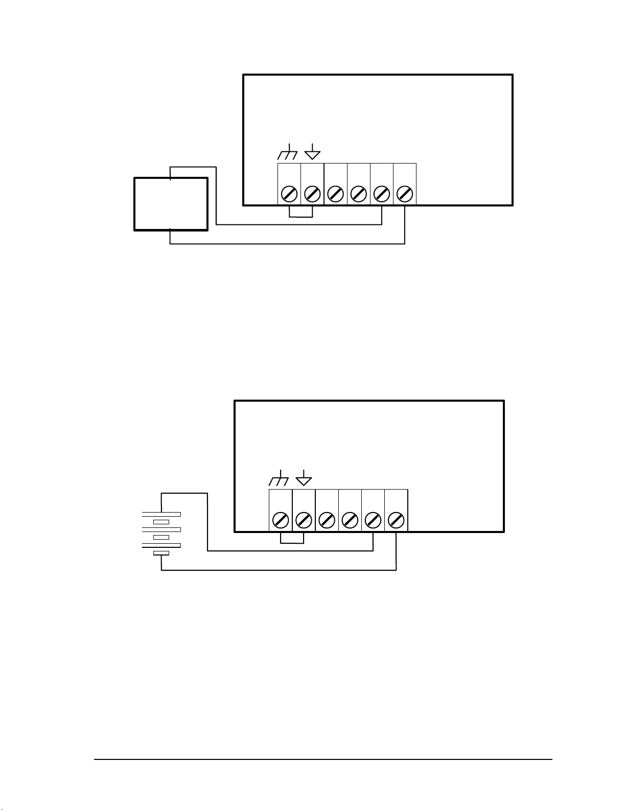
3.2.4 Recommended DC Power Supply Configuration
This configuration uses a single power supply to power the SCADAPack 32P. A 12-24VDC source
is applied to the DC PWR inputs (+) and (-).
The DC power supply input inrush current can be reduced if required. Some DC power supplies will
go into current limit when starting up into a high inrush current load. Battery operated systems have
high current capabilities that may cause nuisance fuse blowing. If either of these situations are
present in an installation, it possible to reduce the DC power supply inrush current by cutting link J3.
J3 is located on the controller next to the power input connector and fuses. This link may be cut in
DC applications only.
SCADAPack 32P Controller Hardware Manual
May 26, 2006
9
Page 11
SCADAPack 32P
–
+
12 - 24Vdc
Power Supply
P3
AC/DC
PWR IN
123456
DC PWR
+ –
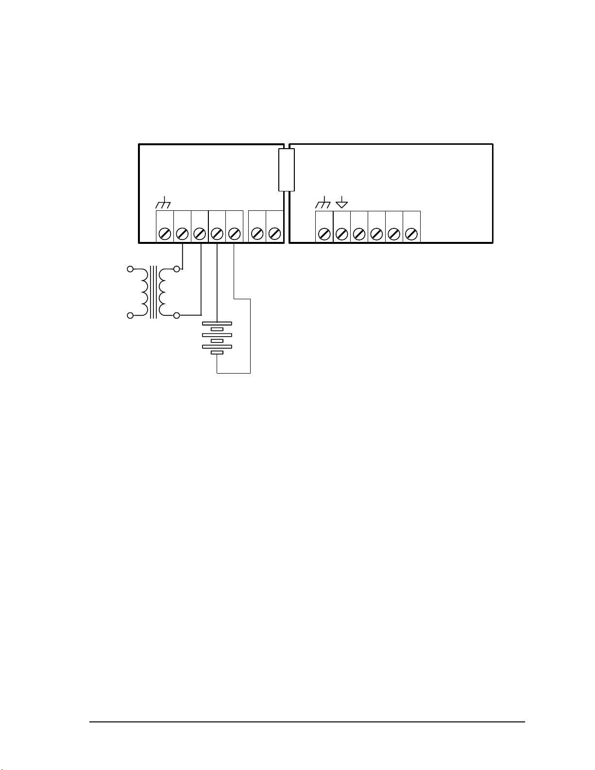
3.2.5 Recommended 24VDC Battery Supply Configuration
This configuration uses a high capacity source, such as a battery, to power the SCADAPack 32P. An
11 – 24VDC battery source is applied with the positive to the AC PWR IN terminal 3 and the
negative to DC PWR (-).
The DC power supply input inrush current can be reduced if required. Battery operated systems have
high current capabilities that may cause nuisance fuse blowing. It possible to reduce the DC power
supply inrush current by cutting link J3. J3 is located on the controller next to the power input
connector and fuses. This link may be cut in DC applications only.
SCADAPack 32P
24V Battery
Supply.
P3
123456
AC/DC
PWR IN
DC PWR
+ –
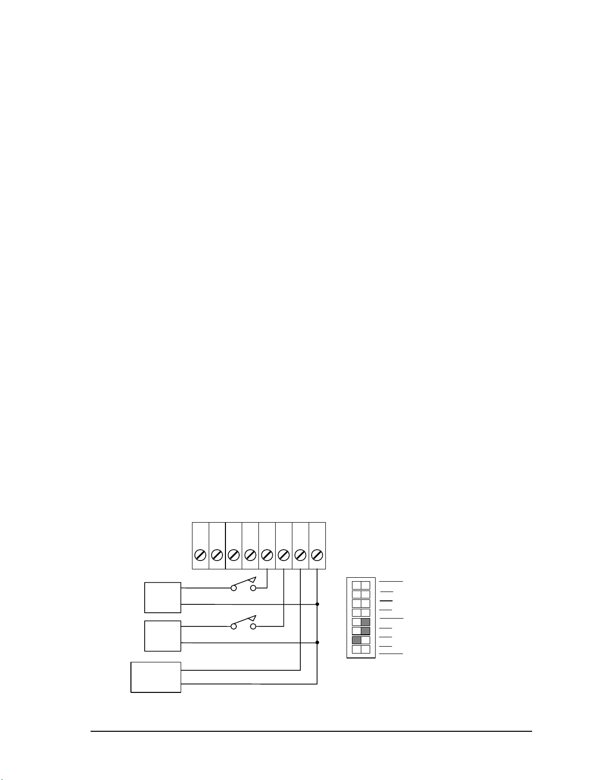
3.2.6 Recommended 5103 Power Supply Configuration
When additional power is required by the system, 5000 Series 5103 power supplies can be used in
combination with the SCADAPack 32P controllers. Refer to the System Configuration Guide for
more information.
The 5103 power supplies can be connected anywhere downstream (to the right) of the controller.
They will supply power to the modules downstream of them.
The 5103 power supply may also be connected upstream (to the left) of any SCADAPack 32P
Controller, but only if no power is applied to the power inputs of the SCADAPack 32P.
SCADAPack 32P Controller Hardware Manual
May 26, 2006
10
Page 12
This configuration uses a 5103 Power Supply module to power a SCADAPack 32P. The 5103 power
s
supply provides a 5V output to power the SCADAPack 32P and 5000 Series modules through the
IMC cables.
Note that no connection is made to the AC/DC PWR IN or DC PWR terminals on the SCADAPack
32P.
5103 Power Supply
SCADAPack 32P
+ -
24V
P3
10
9
Optional 12 Volt
Gel Cel Battery
123456
AC/DC
PWR IN
DC PWR
+ –
P3
120
Vrm
Cl ass 2
Transformer
+ -
AC/DC
1 2 3 4 5
24
Vrms
BATT
3.2.7 System Grounding
In most applications, it is desirable to ground the system by connecting the system power supply
common, to the chassis or panel ground.
On the SCADAPack 32P, the – side of both the 5V and the 24V supplies are connected to the
enclosure. Pins 1 and 2 on P3 are connected internally to the enclosure.
3.3 Internal Analog Inputs
The SCADAPack 32P Controller has two internal analog inputs. These internal analog inputs are
accessed form the user application program.
The ambient temperature input measures the temperature at the controller circuit board. It is useful
for measuring the operating environment of the controller and returns an integer value in the range –
40 to 75 deg C or –40 to 167 deg F. The temperature reading represents temperatures in the range 40°C to 75°C or -40°F to 167°F. Temperatures outside this range cannot be measured.
• For TelePACE applications use the AIN Controller Temperature register assignment to read the
ambient temperature in degrees C and degrees F.
• For ISaGRAF applications use the aintemp I/O connection to read the ambient temperature in
degrees C and degrees F.
The lithium battery input measures the voltage of the battery that maintains the non-volatile RAM in
the controller. The reading returned from this input is in the range from 0 – 5000 representing the
battery voltage in mV. It is useful in determining if the battery needs replacement. The 3.6V lithium
battery will return a typical value of 3600 or 3700. A reading less than 3000 (3.0V) indicates that the
lithium battery requires replacement.
SCADAPack 32P Controller Hardware Manual
May 26, 2006
11
Page 13
• For TelePACE applications use the AIN Controller RAM Battery V register assignment to read
–
–
the lithium battery voltage.
• For ISaGRAF applications use the ainbatt I/O connection to read the lithium battery voltage.
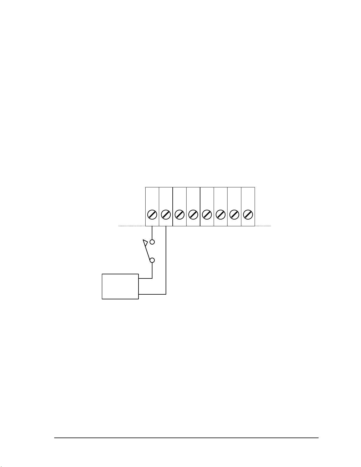
3.4 Digital /Counter Inputs
The SCADAPack 32P has three Digital / Counter inputs. These inputs are labeled DIN\Counter 0, 1
and 2 on the P4 terminal connector. These inputs operate as AC or DC digital inputs or as counter
inputs.
• For DC inputs the maximum input voltage is 30V and the minimum voltage to turn the input ON
is 10V.
• For AC inputs the maximum input voltage is 24Vrms and the minimum voltage to turn the input
ON is 10Vrms.
• For counter inputs the maximum frequency is 5KHz with the filters off.
The DIN/Counter inputs can be used as both digital inputs and counter inputs in an application
program.
• For TelePACE applications use the CNTR Controller Counter Inputs register assignment to
read the DIN/Counter inputs as counters and the DIN Controller Digital Inputs register
assignment to read the DIN/Counter inputs as digital inputs
• For ISaGRAF applications use the cntrCtrl I/O connection to read the DIN/Counter inputs as
counters and the dinCtrl I/O connection to read the DIN/Counter inputs as digital inputs.
Each of the three digital / counter (DIN/Counters) inputs on the SCADAPack 32P controller has a
switch selectable filter, which limits the maximum input frequency. Filtering limits the maximum
digital input or counter frequency to approximately 30Hz. Refer to section 6.7.1-Digital Input
Filters for filter selection information.
• Use a filter for 50 or 60Hz digital inputs and for low speed counting applications that experience
problems due to contact bounce.
• Do not use filtering for high speed counting applications.
An example of wiring each type of input is shown in the diagram below.
DIN/Counter
24V
16Vrms
0
P4
1
+
2
34
5
COM21
6
7
Connection Example:
8
SW1 Filter 0 is ON to debounce contacts.
SW1 Filter 1 is ON to filter AC.
SW1 Filter 2 is OPEN for high speed counting.
SW 1
1
2
Options
3
4
0
1
Filters
2
not us ed
Pulse Output
+
SCADAPack 32P Controller Hardware Manual
May 26, 2006
12
Page 14
3.5 Interrupt Input
–
—
The SCADAPack 32P has one Interrupt digital input. This input is labeled DINT on the P4 terminal
connector. This input operates as a DC digital input or as a counter input.
• For DC input the maximum input voltage is 28V and the minimum voltage to turn the input ON
is 2.5V.
• For counter input the maximum frequency is 500Hz.
The INT input can be used as both a digital input and as a counter in an application program.
• For TelePACE applications use the CNTR Controller Interrupt Input register assignment to
read the INT/Cntr input as a counter and the DIN Controller Interrupt Input register assignment
to read the INT/Cntr input as a digital input.
• For ISaGRAF applications use the cntrint I/O connection to read the INT/Cntr input as a
counter input and the dinint I/O connection to read the INT/Cntr input as a digital input.
The diagram below shows how to wire this input.
INT
+
P4
34
21 5 6 7 8
+
2.5-28V
3.6 Status Output
The SCADAPack 32P status output indicates an alarm condition to an external device. The output is
ON (capable of conducting current) during normal operation. The output is OFF (high impedance)
during the following conditions:
• Power failure.
• SCADAPack 32P RESET.
• Application program defined conditions.
The status output is an optically isolated transistor. The polarity of the output must be observed. The
output current must be limited to 60mA during the ON condition. The output voltage must be limited
to 30V during the OFF condition.
SCADAPack 32P Controller Hardware Manual
May 26, 2006
13
Page 15
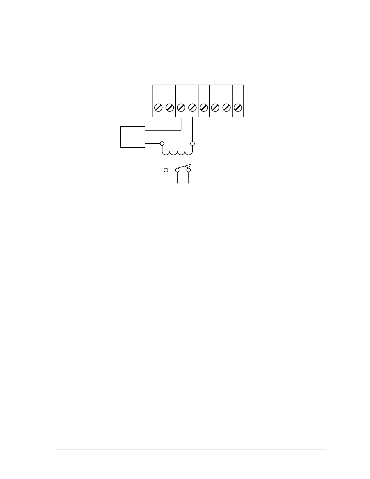
A typical application of this output is shown in the following diagram. The output energizes a relay.
•
A
–
The normally closed contacts of this relay are used to activate an alarm. The relay in this application
has a 24V coil with greater than 400Ω resistance.
STATU S
+
–
P4
34
21 5 6 7 8
24 V
+
Relay Coil Specifications:
•
24V
•
> 400 ohms
< 60m
NCNO COM
NC ALARM CONTACTS:
closed dur ing power
failures and fault
conditions.
SCADAPack 32P Controller Hardware Manual
May 26, 2006
14
Page 16
4 Serial Communication
The SCADAPack 32P controller is equipped with three serial communication ports. All three serial
communication ports support RS-232 serial communication and one port supports both RS-232 and
RS-485 serial communication.
Serial ports on the SCADAPack 32P controller are designated COM1, COM2 and COM4. Refer to
Figure 2: 5232 Controller Module section for the location of the serial ports.
4.1 RS-232 Serial Communications Ports
All RS-232 wiring must use shielded cable. The shield should be connected to chassis ground at one
point. The DE-9 connector shell is a good ground point. Failure to properly shield the cable may
result in the installation not complying with FCC or DOC radio interference regulations.
4.1.1 COM1 RS-232 Serial Port
Serial port COM1 may be configured as an RS-232 or RS-485 serial communication port.
• A jumper must be installed on J10 to operate COM1 in RS-232 mode.
• A jumper must be installed on J9 to operate COM1 in RS-485 mode.
Refer to Figure 2: 5232 Controller Module for the location of COM1 and jumpers J9 and J10.
For information on using COM1 as a RS-485 serial port refer to section 4.4-RS-485 Serial
Communication Port.
Connections to COM1 are made through a RJ-45 modular connector. The wiring and pin
connections for this connector are described in section 4.1.4-RJ-45 Modular Connector for RS-232.
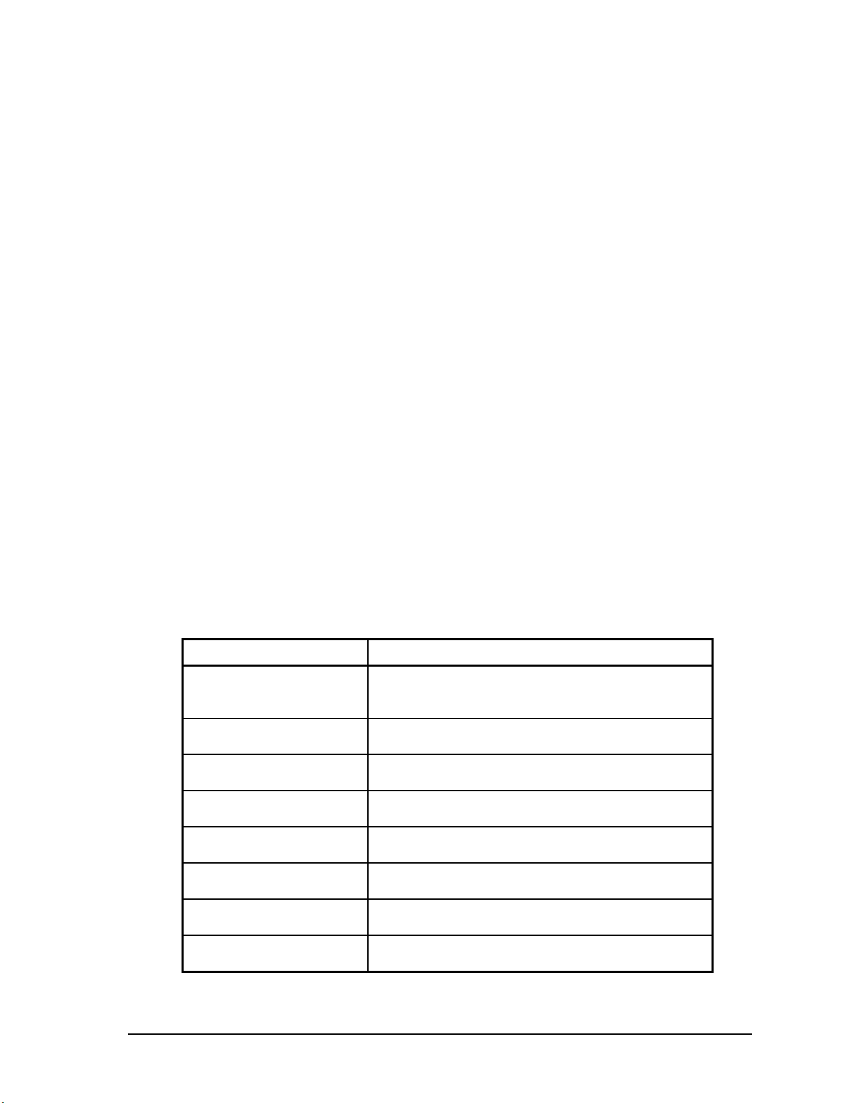
The following table shows the serial and protocol communication parameters supported by COM1.
These parameters are set from TelePACE, ISaGRAF Workbench or from an application program
running in the SCADAPack 32P controller. Default values are set when a Cold Boot or Service Boot
is performed on the SCADAPack 32P controller.
Parameter Supported Values
Baud Rate
Duplex
Parity
Data Bits
Stop Bits
Receive Flow Control
Transmit Flow Control
Station
300, 600, 1200, 2400, 4800, 9600, 19200, 38400,
57600 and 115200.
Default: 9600
Full or Half
Default: Full
Odd, None or Even
Default: None
7 or 8 Bits
Default: 8 Bits
1 or 2 Bits
Default: 1 Bit
ModbusRTU or None
Default: ModbusRTU
Ignore CTS or None
Default: None
1 to 65534
Default: 1
SCADAPack 32P Controller Hardware Manual
May 26, 2006
15
Page 17
Parameter Supported Values
Protocol
Addressing Mode
None, Modbus RTU or Modbus ASCII
Default: Modbus RTU
Standard or Extended
Default: Standard
4.1.2 COM2 RS-232 Serial Port
Connections to COM2 are made through a RJ-45 modular connector. The wiring and pin
connections for this connector are described in section 4.1.4-RJ-45 Modular Connector for RS-232.
Refer to section 3.1- Field Wiring Connections for the location of COM2 on the SCADAPack 32P.
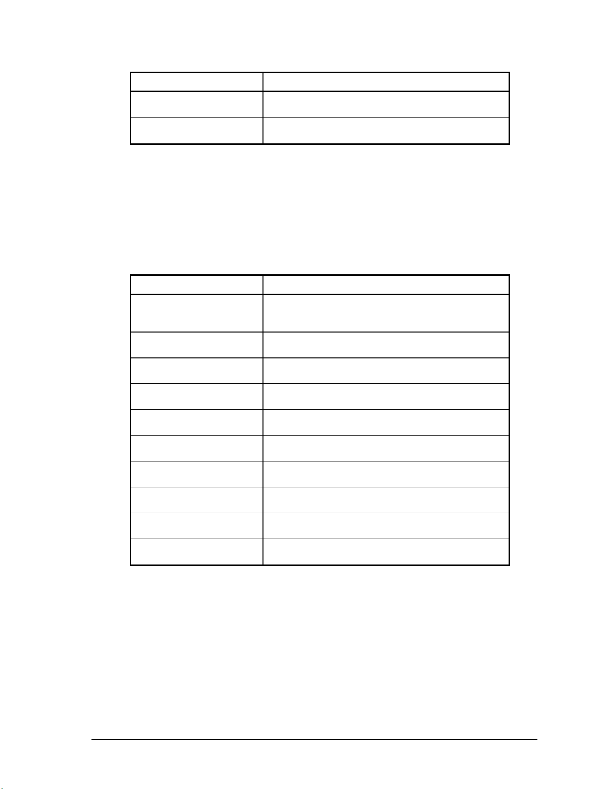
The following table shows the serial and protocol communication parameters supported by COM2.
These parameters are set from TelePACE, ISaGRAF Workbench or from an application program
running in the SCADAPack 32P controller. Default values are set when a Cold Boot or Service Boot
is performed on the SCADAPack 32P controller.
Parameter Supported Values
Baud Rate
Duplex
Parity
Data Bits
Stop Bits
Receive Flow Control
Transmit Flow Control
Station
Protocol
Addressing Mode
300, 600, 1200, 2400, 4800, 9600, 19200, 38400,
57600 and 115200.
Default: 9600
Full or Half
Default: Full
Odd, None or Even
Default: None
7 or 8 Bits
Default: 8 Bits
1 or 2 Bits
Default: 1 Bit
ModbusRTU or None
Default: ModbusRTU
Ignore CTS or None
Default: None
1 to 65534
Default: 1
None, Modbus RTU or Modbus ASCII
Default: Modbus RTU
Standard or Extended
Default: Standard
4.1.3 COM4 RS-232 Serial Port
Connections to COM4 are made through a RJ-45 modular connector. The wiring and pin
connections for this connector are described in section 4.1.4-RJ-45 Modular Connector for RS-232.
Refer to section 3.1- Field Wiring Connections for the location of COM4 on the SCADAPack 32P.
The following table shows the serial and protocol communication parameters supported by COM4.
These parameters are set from TelePACE, ISaGRAF Workbench or from an application program
running in the SCADAPack 32P controller. Default values are set when a Cold Boot or Service Boot
is performed on the SCADAPack 32P controller.
SCADAPack 32P Controller Hardware Manual
May 26, 2006
16
Page 18
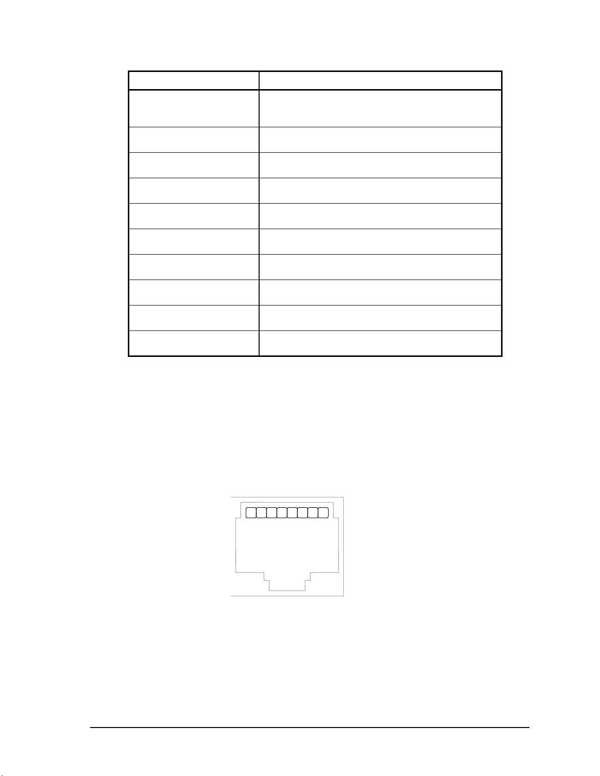
Parameter Supported Values
Baud Rate
300, 600, 1200, 2400, 4800, 9600, 19200, 38400,
57600 and 115200.
Default: 9600
Duplex
Full or Half
Default: Full
Parity
Odd, None or Even
Default: None
Data Bits
7 or 8 Bits
Default: 8 Bits
Stop Bits
1 or 2 Bits
Default: 1 Bit
Receive Flow Control
ModbusRTU or None
Default: ModbusRTU
Transmit Flow Control
Ignore CTS or None
Default: None
Station
1 to 65534
Default: 1
Protocol
None, Modbus RTU or Modbus ASCII
Default: Modbus RTU
Addressing Mode
Standard or Extended
Default: Standard
4.1.4 RJ-45 Modular Connector for RS-232
Serial communication ports COM1, COM2 and COM4 are located on the SCADAPack 32P
SCADAPack 32P. These are RS-232 serial ports using a 8-pin female RJ-45 connectors configured
as Data Terminal Equipment (DTE). The recommended specification for RS-232 cable length is a
maximum of 50 feet or 15.2 meters. Shielded cable must be used and the shield should be connected
to chassis ground at one end.
The following diagram shows the pin connections for the RS-232 (RJ-45) port connector for COM1,
COM2 and COM4.
RJ-45 Modular Jack
21 876543
Notes:
• +5V is only available on Pin 1 when a jumper is installed on J4. Refer to section 3.1- Field
Wiring Connections for the location of J4.
1. +5V
2. DCD
3. DTR
4. GND
5. RxD
6. TxD
7. CTS
8. RTS
• Serial port COM1 may be configured as RS-232 or RS-485. A jumper must be installed on J10
to operate COM1 in RS-232 mode. Refer to section 3.1- Field Wiring Connections for the
location of J10.
SCADAPack 32P Controller Hardware Manual
May 26, 2006
17
Page 19
The following table provides a description of the function of each pin of the RJ-45 connector. In this
R
S
S
s
s
table a MARK level is a voltage of +3V or greater and a SPACE level is a voltage of –3V or less.
Pin Function Description
1 5V
(Output)
2 DCD
(Input)
3 DTR
(Output)
4 GND This pin is connected to the system ground.
5 RxD
(Input)
6 TxD
(Output)
7 CTS
(Input)
8 RTS
(Output)
This pin can be connected to the 5V power supply by installing a
jumper at J4 on the SCADAPack controller board.
The DCD led is on for a MARK level.
This pin is normally at a MARK level.
This pin is at a SPACE level when DTR is de-asserted.
The level is SPACE on standby and MARK for received data.
The LED is lit for a MARK level.
The level is SPACE on standby and MARK for transmitted data.
The LED is lit for a MARK level.
This level must be a MARK for the communication port to
transmit data. When the attached device does not provide this
signal, the controller keeps the line at a MARK.
When the attached device does provide this signal, it must set
CTS to MARK to allow the controller to transmit data.
This pin is a MARK if full-duplex operation is selected for the
port.
This pin is set to a MARK just before and during transmission of
data if half-duplex operation is selected.
This pin is set to a SPACE when no data is being transmitted.
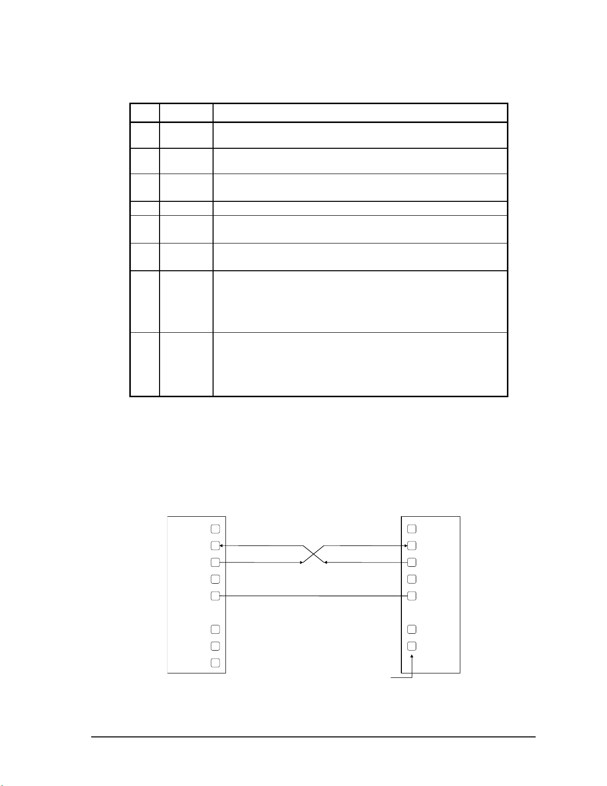
4.2 RS-232 Wiring Examples
4.2.1 DTE to DTE without Handshaking
There are several methods for wiring the RS-232 COM port to DTE (Data Terminal Equipment) and
DCE (Data Communications Equipment) devices. The simplest connection requires only 3 wires:
RxD, TxD and signal ground. The following diagram shows a common RS-232 COM port to DTE
device.
RS-232 COM port (DTE) DTE
DCD
RxD
TxD
DT
GND
RT
CT
+5V
See device
specification
for pin number
DCD
RxD
TxD
DTR
GND
RTS
CTS
SCADAPack 32P Controller Hardware Manual
May 26, 2006
18
Page 20
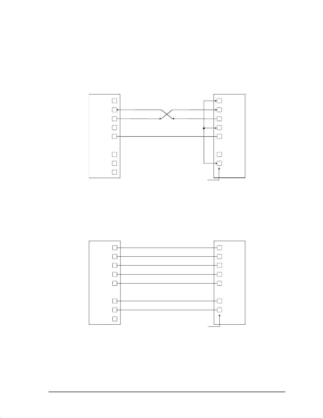
4.2.2 DTE to DTE with Handshaking
R
S
S
e
s
s
R
S
S
s
s
Some DTE devices may require hardware handshaking lines. The most common are the CTS and
RTS lines. Less common are the DTR and DCD lines. The controller does not require these lines.
Refer to the specifications of the external device for exact requirements. The following diagram
shows a common connection of an RS-232 COM port with a DTE device requiring handshaking
lines.
RS-232 COM port (DTE) DTE
DCD
RxD
TxD
DT
GND
RT
CT
+5V
See d evi c
specification
for pin number
DCD
RxD
TxD
DTR
GND
RTS
CTS
4.2.3 DTE to DCE with Handshaking
DCE devices require different wiring. The handshaking lines must be connected in most cases. Note
that many DCE devices are half duplex. Select half-duplex operation with these devices. The
diagram below shows common connection of a SCADAPack with a DCE device requiring
handshaking lines.
RS-232 COM port (DTE) DCE
DCD
RxD
TxD
DT
GND
DCD
RxD
TxD
DTR
GND
RT
CT
+5V
SCADAPack 32P Controller Hardware Manual
See device
specification
for pin number
RTS
CTS
19
May 26, 2006
Page 21
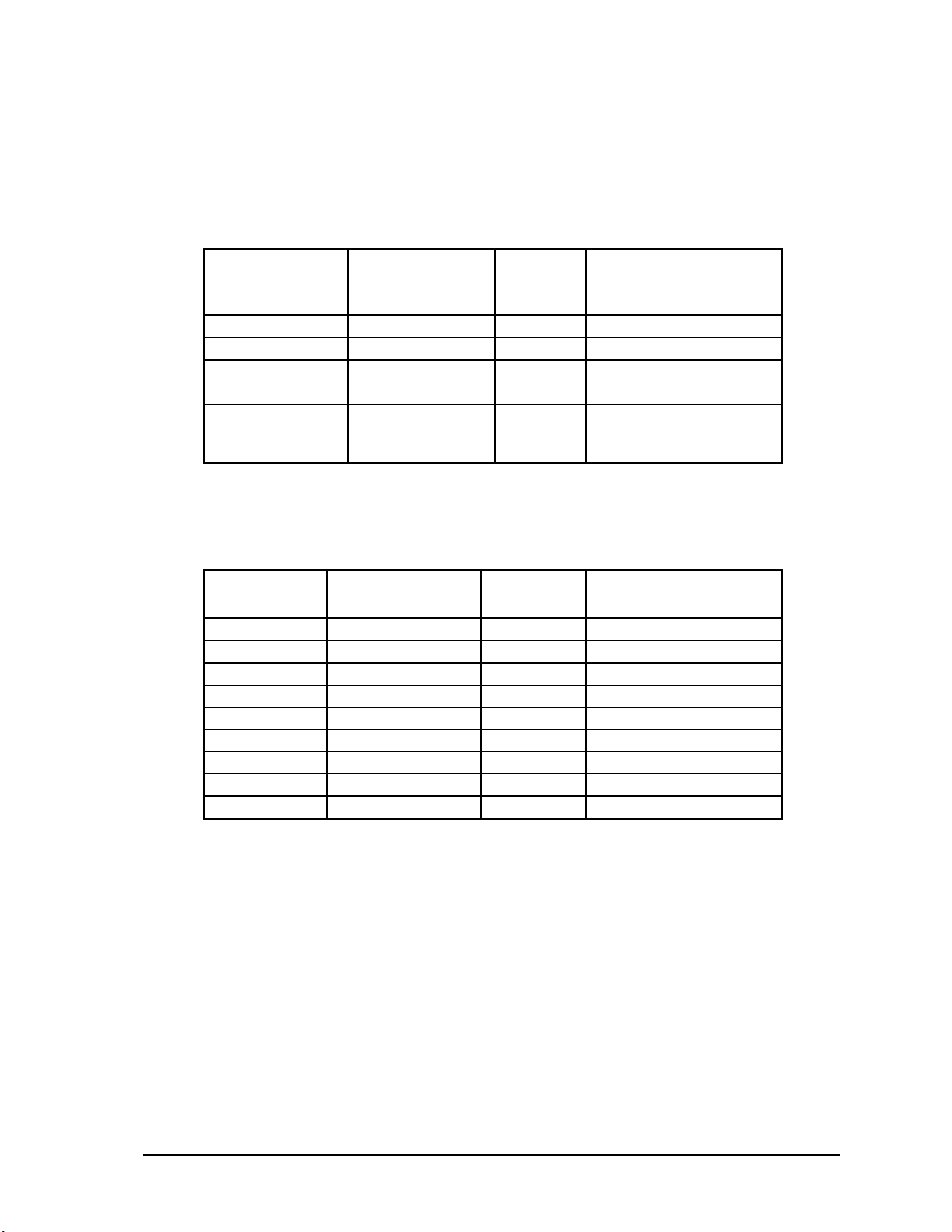
4.3 RS-232 Cables
4.3.1 RJ-45 to DE-9S DTE
This cable is used to connect from an RJ-45 based RS-232 port on the SCADAPack 32P controller to
DE-9P connector on a DTE such as a PC. A 10 ft. long cable is available from Control Microsystems
as part number 297217.
RJ-45
8 Pins
Shield connects to shell
6 TxD RxD 2
5 RxD TxD 3
4 GND GND 5
1, 2, 3, 7 and 8
are not connected
at this end.
SCADAPack 32P
DTE Function
GND GND No wires connected at
DE9S
DTE
Function
DE9S
this end.
4.3.2 RJ-45 to DE-9P DCE
This cable is used to connect from an RJ-45 based RS-232 port on the SCADAPack 32P controller to
DE-9S connector on a DCE such as a modem. A 15 inch long cable is available from Control
Microsystems as part number 297218.
RJ45 SCADAPack 32P
DTE Function
Shield connects to shell
3 DTR DTR 4
6 TxD TxD 3
5 RxD RxD 2
2 DCD DCD 1
4 GND GND 5
7 CTS CTS 8
8 RTS RTS 7
1 +5V +5V 9
DE-9P DCE
Function
DE-9P
4.4 RS-485 Serial Communication Port
Serial port COM1 on the SCADAPack 32 controller may be configured as an RS-485 serial
communication port. A jumper must be installed on J9 to operate COM1 in RS-232 mode. Refer to
section 3.1-Field Wiring Connections for the location of J9.
When configured as a RS-485 port COM1 transmits and receives differential voltages to other RS485 devices on a network. The RS-485 specification allows a maximum of 32 devices connected on
a single RS-485 network. The recommended specification for RS-485 is the cable length should not
exceed a maximum of 4000 feet or 1200 meters. Termination resistors are required when using long
cable lengths and high baud rates. Refer to section 4.4.3-RS-485 Termination Resistors for
information on termination resistors.
The signal grounds of the RS-485 devices in the network are not connected together but instead are
referenced to their respective incoming electrical grounds. The grounds of the RS-485 devices on the
network must be within several volts of each other.
SCADAPack 32P Controller Hardware Manual
May 26, 2006
20
Page 22
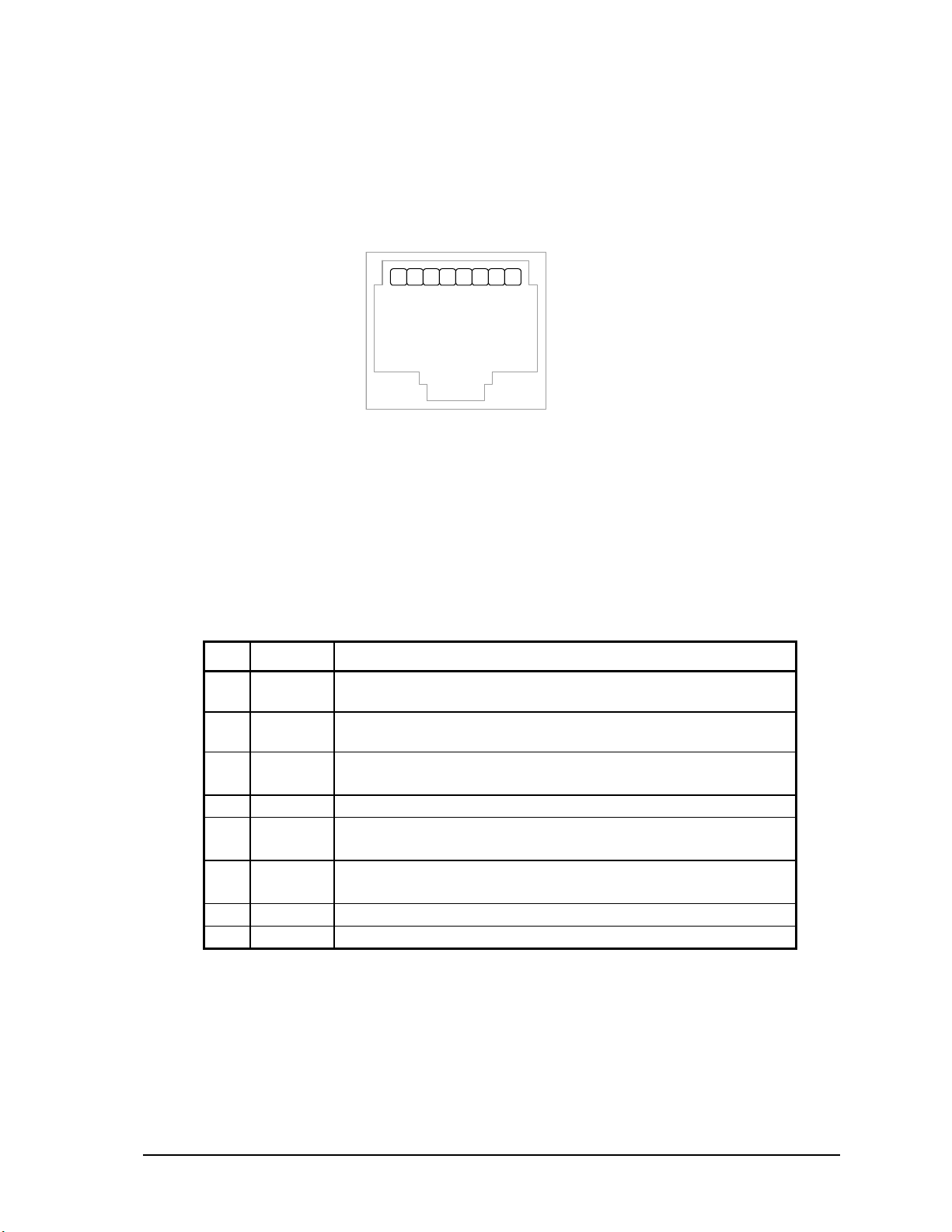
The RS-485 port operates in two or four wire mode.
4.4.1 RJ-45 Modular Connector for RS-485
The following diagram shows the pin connections for the RS-485 (RJ-45) port connector for COM1.
RJ-45 Modular Jack
Black
1. +5V
21 876543
+5V is only available on Pin 1 when a jumper is installed on J4. Refer to section 3.1-Field Wiring
Connections for the location of J4.
Serial port COM1 may be configured as RS-232 or RS-485. A jumper must be installed on J9 to
operate COM1 in RS-485 mode. Refer to section 3.1- Field Wiring Connections for the location of
J9.
The differential receive and transmit signals are labeled +/–Rx and +/–Tx respectively. Some RS-485
devices refer to the – side of the signal as A and the + side of the signal as B.
2. –Rx
3. –Tx
4. GND
5. +Rx
6. +Tx
7. Do not
connec t
8. Do not
connec t
The following table provides a description of the function of each pin of the RJ-45 connector. In this
table a MARK level is a voltage of +3V or greater and a SPACE level is a voltage of –3V or less.
Pin Function Description
1 5V
(Output)
2 -Rx
This pin can be connected to the 5V power supply by installing a
jumper at J4 on the SCADAPack 32P.
The DCD led is on for a MARK level.
(Input)
3 -Tx
(Output)
This pin is normally at a MARK level.
This pin is at a SPACE level when DTR is de-asserted.
4 GND This pin is connected to the system ground.
5 +Rx
(Input)
6 +Tx
(Output)
The level is SPACE on standby and MARK for received data.
The LED is lit for a MARK level.
The level is SPACE on standby and MARK for transmitted data.
The LED is lit for a MARK level.
7 N/C Do not connect this pin for RS-485 operation.
8 N/C Do not connect this pin for RS-485 operation.
4.4.2 RS-485 Bias Resistors
The RS-485 receiver inputs on the SCADAPack 32P controller are biased to ensure that that received
data is driven to a valid state (space) when there are no active drivers on the network. The value of
these bias resistors is 4700 ohms from Ground to the –Rx input and 4700 ohms from +5V to the +Rx
input.
SCADAPack 32P Controller Hardware Manual
May 26, 2006
21
Page 23

4.4.3 RS-485 Termination Resistors
Termination resistors are required in long networks operating at the highest baud rates. Shorter
networks in high noise environments may also benefit from terminations. Networks as long 1000 ft.
operating at 9600 baud will function without termination resistors. Terminations should be
considered if the baud rate is higher and the network is longer.
When termination resistors are required, they are installed on the first and last station on the RS-485
wire pair. All other stations should not have termination resistors.
RS-485 networks are generally terminated with 120 ohm resistors on each end. The required 120
ohm resistor is built into the SCADAPack 32P controller. When these termination resistors are used,
the biasing generally has to be increased in order to generate at least 0.2V across the +/–Rx input.
To connect the termination resistors:
• Install a jumper across J8 to terminate the Rx pair.
• Install a jumper across J7 to terminate the Tx pair.
To disconnect the termination resistors:
• Remove the jumper across J8 to terminate the Rx pair.
• Remove the jumper across J7 to terminate the Tx pair.
4.5 RS-485 Wiring Examples
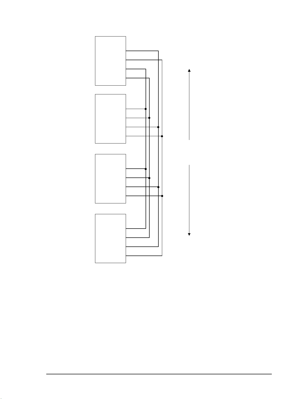
4.5.1 Four wire mode
Four-wire operation uses one pair of wires for transmitting data and a second pair for receiving data.
The transmitting pair is connected to +Tx and –Tx. The receiving pair is connected +Rx and –Rx.
The following diagram shows the wiring details for a four-wire connection.
SCADAPack 32P Controller Hardware Manual
May 26, 2006
22
Page 24
X
–TX
–RX+RX
X
–TX
–RX+RX
X
–TX
–RX+RX
X
–TX
–RX+RX
M ASTER
+T
SLAVE
+T
SLAVE
First station in network
may require termination.
RS-485 network
4000 feet (1200 m)
maximum length
+T
SLAVE
Last station in network
may require terminations.
+T
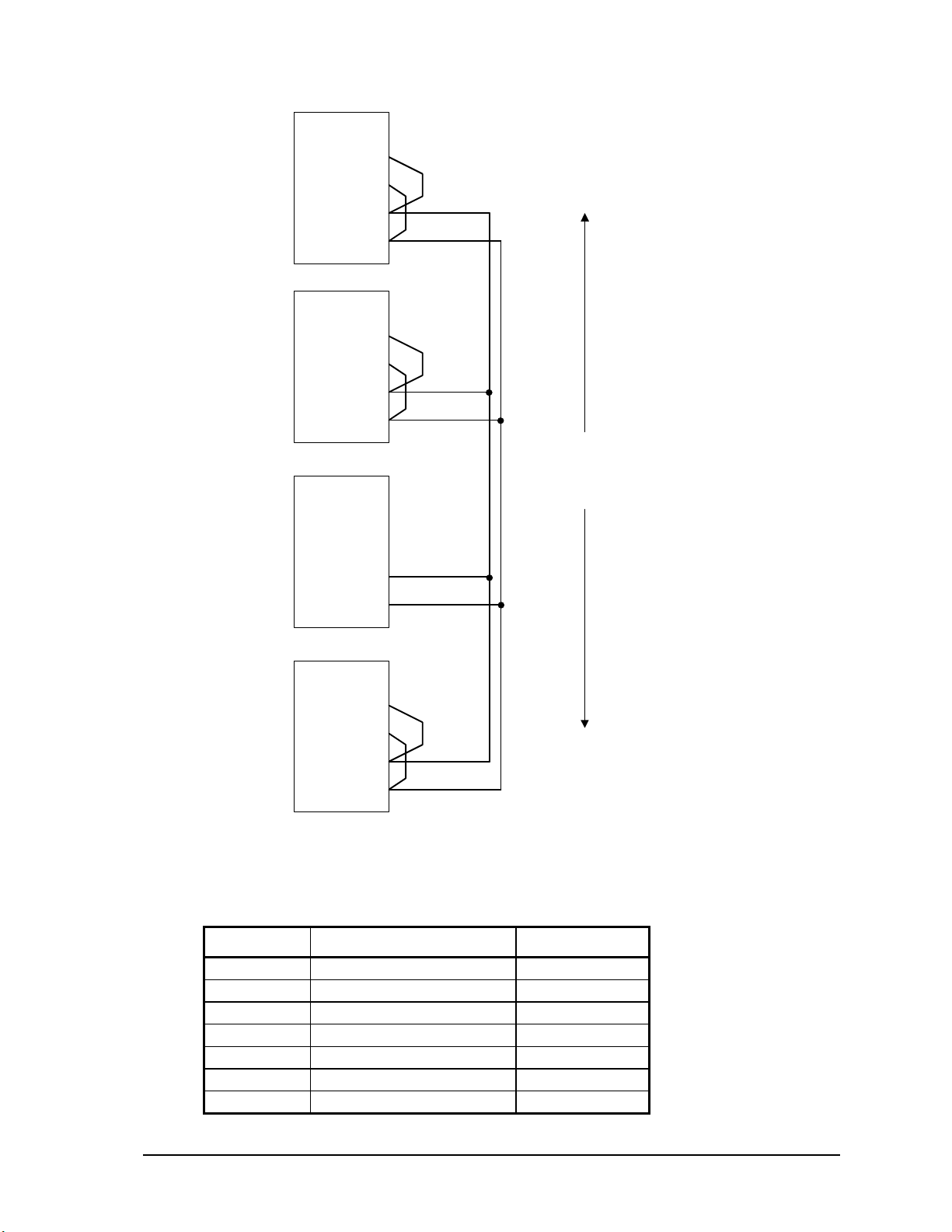
4.5.2 Two wire mode
Two wire operation uses one pair of wires for transmitting and receiving data. +Tx must be
connected to +Rx and –Tx must be connected to the –Rx. This pair of wires becomes the
transmitting and receiving pair. The following diagram shows the wiring details for a two wire
connection.
SCADAPack 32P Controller Hardware Manual
May 26, 2006
23
Page 25
X
–TX
–RX+RX
X
–
X
X
–TX
–RX+RX
X
–TX
–RX+RX
5232
+T
5232
+T
Other RS-
485 Device
TX/R
First station in network
may require terminations.
RS-485 network
4000 feet (1200 m)
maximum length
+TX/R
5232
Last station in network
may require terminations.
+T
4.6 RS-485 Cable
This cable is used to connect from an RJ-45 based RS-485 port on the SCADAPack 32P controller to
other RS-485 devices. The cable has a RJ-45 connector on one end and stripped wires at the other
end. A 10-foot long cable is available from Control Microsystems as part number 297234.
RJ45 Function Wire color
Connect to Chassis Shield
3 –Tx Orange
6 +Tx Blue
5 +Rx Grey
2 –Rx Brown
4 GND Black
7 Do not connect. Yellow
SCADAPack 32P Controller Hardware Manual
May 26, 2006
24
Page 26

RJ45 Function Wire color
8 Do not connect. Green
1 +5V Red
SCADAPack 32P Controller Hardware Manual
May 26, 2006
25
Page 27
5 Ethernet Communication
The SCADAPack 32P controller has one 10BaseT Ethernet port. 10BaseT is a single
communications channel running at 10MHz over unshielded, twisted - pair cabling. 10BaseT uses
differential signaling.
5.1 LAN Port Settings
Connections to the LAN port are made through a RJ-45 modular connector. The wiring and pin
connections for this connector are described in section 5.1.3-RJ-45 Modular Connector for
Ethernet.
Refer to section 3.1-Field Wiring Connections for the location of the LAN port on the SCADAPack
32P.
5.1.1 TCP/IP Settings
The following table shows the TCP/IP parameters supported by the LAN port. These parameters are
set from the ISaGRAF Workbench or from an application program running in the SCADAPack 32P
controller. Default values are set when a Cold Boot is performed on the SCADAPack 32P controller.
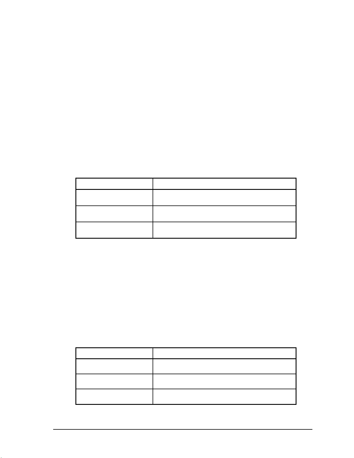
Parameter Supported Values
IP Address
Subnet Mask
Gateway
The IP Address is the address of the controller. The IP address is statically assigned. Contact your
network administrator to obtain an IP address for the controller.
In the format 255.255.255.255
Default: 0.0.0.0
In the format 255.255.255.255
Default: 0.0.0.0
In the format 255.255.255.255
Default: 0.0.0.0
The Subnet Mask is determines the subnet on which the controller is located. The subnet mask is
statically assigned. Contact your network administrator to obtain the subnet mask for the controller.
The Gateway determines how your controller communicates with devices outside its subnet. Enter
the IP address of the gateway. The gateway is statically assigned. Contact your network
administrator to obtain the gateway IP address.
5.1.2 Modbus/TCP Settings
The following table shows the Modbus/TCP parameters supported by the LAN port. These
parameters are set from the ISaGRAF Workbench or from an application program running in the
SCADAPack 32P controller. Default values are set when a Cold Boot or Service Boot is performed
on the SCADAPack 32P controller.
Parameter Supported Values
Master Idle Timeout
Server Receive Timeout
Maximum Server
Connections
Any value in seconds.
Default: 10 seconds
Any value in seconds.
Default: 10 seconds
Valid values are 1 to 20.
Default: 20
SCADAPack 32P Controller Hardware Manual
May 26, 2006
26
Page 28
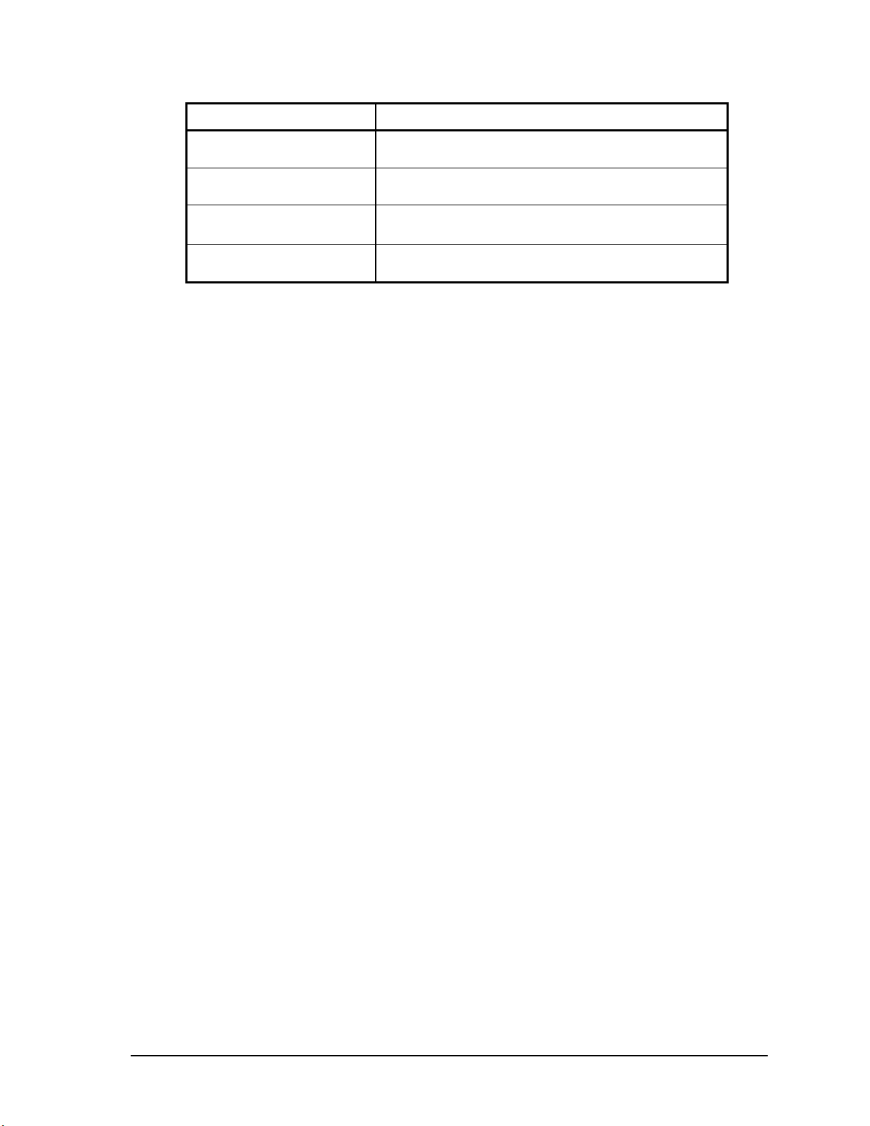
Parameter Supported Values
TCP Port
Modbus Addressing Type
Modbus Station Address
Store and Forward
Messaging
Valid values are 1 to 65535
Default: 502
Valid values are Standard or Extended
Default: Standard
Valid values are 1 to 65534.
Default: 1
Valid values are Enabled and disabled.
Default: Disabled
The Master Idle Timeout parameter sets when connections to a slave controller are closed. Setting
this value to zero disables the timeout; the connection will be closed only when your program closes
it. Any other value sets the timeout in seconds. The connection will be closed if no messages are sent
in that time. This allows the slave device to free unused connections.
The Server Receive Timeout parameter sets when connections from a remote device are closed.
Setting this value to zero disables the timeout; the connection will be closed only when the remote
device closes it. Any other value sets the timeout in seconds. The connection will be closed if no
messages are received in that time. This allows the controller to free unused connections.
The Maximum Server Connections parameter sets the number of incoming (server) connections
that the controller will allow. Incoming (server) connections are used when a remote device creates a
connection to this controller. Outgoing connections are used when this controller creates a
connection to a remote device (e.g. using a masterip function block). Setting this value to the
maximum allows the server to use all connections for incoming connections. Setting the value below
the maximum limits the number of incoming connections from remote devices. This reserves the
remaining connections for use by the controller for outgoing connections.
The TCP Port parameter sets the port used by the Modbus/TCP protocol. In almost all cases this
should be set to 502. This is the well-known port number for Modbus/TCP. Modbus/TCP devices
use 502 by default, and on many devices the value cannot be changed. It is suggested that you
change this value only if this port is used by another service on your network. Consult your network
administrator to obtain a port if you are not using the default.
The Addressing parameter selects standard or extended Modbus addressing. Standard addressing
allows 255 stations and is compatible with standard Modbus devices. Extended addressing allows
65534 stations, with stations 1 to 254 compatible with standard Modbus devices.
The Station parameter sets the station number of the controller. The valid range is 1 to 255 if
standard addressing is used, and 1 to 65534 if extended addressing is used.
The Store and Forward Messaging parameter controls forwarding of messages on the Ethernet
port. If this option is enabled, messages will be forwarded according to the settings in the store and
forward routing table.
5.1.3 RJ-45 Modular Connector for Ethernet
The SCADAPack 32P can be connected directly to a wall jack or hub using standard RJ-45 Category
5 patch cables. The following diagram shows the pin connections for the RJ-45 modular connector.
SCADAPack 32P Controller Hardware Manual
May 26, 2006
27
Page 29

RJ-45 M odular Jack
Grey
21 876543
1. +Tx
2. –Tx
3. +Rx
4.
5.
6. –Rx
7.
8.
10BaseT has a maximum run of 100m or 350 feet, but the actual limit is based on signal loss and the
noise in the environment. This may limit the practical distance to less than 100m or 350 feet. The
Ethernet cables should not be run in parallel with power or any cables that generate noise.
SCADAPack 32P Controller Hardware Manual
May 26, 2006
28
Page 30

6 Operation
Operating Modes
SCADAPack 32P Controllers may start up in RUN, SERVICE or COLD BOOT mode. Start up in
the RUN mode automatically executes the application programs in the controller memory. Start up in
the SERVICE mode stops the programs to allow reprogramming and controller initialization. Start
up in the COLD BOOT mode initializes the controller and erases all programs.
6.1 Run Mode
The RUN mode is the normal operating mode of the SCADAPack 32P Controller. No action is
required to select RUN mode. When power is applied to the SCADAPack 32P:
• The user defined serial communication parameters, for all COM ports are used.
• The user defined TCP/IP and Modbus/TCP parameters are used for the Ethernet port.
• If a TelePACE or ISaGRAF application program is loaded it is executed.
• If a TelePACE or ISaGRAF C/C++ application program is loaded and the program checksum is
correct, it is executed.
The controller lock settings and password are used.
6.2 Service Mode
SERVICE mode is used during application programming and maintenance work. When the
SCADAPack 32P controller starts in SERVICE mode:
• The default serial communication parameters are used. See section 4.1- RS-232 Serial
Communications Ports of this manual for a description of the default parameters.
• The user defined TCP/IP parameters are used for the Ethernet port.
• The default Modbus/TCP parameters are used for the Ethernet port. See section 5.1.2-
Modbus/TCP Settings of this manual for the default parameters.
• If a TelePACE or ISaGRAF application program is loaded it is stopped.
• If an ISaGRAF C++ application program is loaded it is stopped.
• All programs are retained in non-volatile memory.
• The controller lock settings and password are used.
SERVICE mode is selected by performing a SERVICE BOOT using the following procedure:
• Remove power from the SCADAPack 32P controller.
• Hold down the LED POWER button.
• Apply power to the controller.
• Continue holding the LED POWER button until the STAT LED turns on.
• Release the LED POWER button.
Note: If the LED POWER button is released before the STAT LED turns on, the SCADAPack 32P
controller will start in RUN mode.
SCADAPack 32P Controller Hardware Manual
May 26, 2006
29
Page 31
6.3 Cold Boot Mode
COLD BOOT mode is used after installing new controller firmware. When the SCADAPack 32P
controller starts in COLD BOOT mode:
The default serial communication parameters are used. See section 4.1-RS-232 Serial
Communications Ports of this manual for a description of the default parameters.
The default TCP/IP parameters are used for the Ethernet port. See section 5.1.1-TCP/IP Settings of
this manual for the default parameters.
• The default Modbus/TCP parameters are used for the Ethernet port. See section 5.1.2-
Modbus/TCP Settings of this manual for the default parameters.
• The TelePACE or ISaGRAF application program is erased.
• The ISaGRAF C++ application program is erased.
• The controller is unlocked.
COLD BOOT mode is selected by performing a COLD BOOT using the following procedure:
• Remove power from the controller.
• Hold down the LED POWER button.
• Apply power to the controller.
• Continue holding the LED POWER button for 25 seconds until the STAT LED begins to flash
on and off continuously.
• Release the LED POWER button.
Note: If the LED POWER button is released before the STAT LED begins to flash, the
SCADAPack 32P controller will start in SERVICE mode.
6.4 SCADAPack 32P LED Indicators
There are twenty-three LEDs on the SCADAPack 32P SCADAPack 32P. These LEDs are used to
indicate the operational status of the controller. All LEDs except the 5V LED can be disabled to
conserve power. Refer to section 6.5-LED Power Control for details on LED power control.
The following table describes the SCADAPack 32P SCADAPack 32P LEDs.
LED Function
5V
RUN
LEDS
STAT
FORCE
On when 5V power is present in the SCADAPack 32P
controller. The controller must have 5V power to operate. 5V
power is supplied by the SCADAPack 32P internal power
supply or from an external model 5103 power supply.
On when an ISaGRAF application program is running in the
SCADAPack 32P controller. This LED may be controlled by
a C++ Tools application, in which case the application will
control the LED status.
On when LED power is enabled.
This LED is normally off. The LED will blink when an error
exists. Refer to section for more information on this LED
and the STATUS output.
On when and SCADAPack 32P I/O points are forced, or
locked, in an ISaGRAF application.
SCADAPack 32P Controller Hardware Manual
May 26, 2006
30
Page 32
LED Function
INT/Counters 0
INT/Counters 1
INT/Counters 2
INT
LAN
LINK
COM1 RX
COM2 RX
COM4 RX.
COM1 TX
COM2 TX
COM4 TX.
COM1 CTS
COM2 CTS
COM4 CTS.
COM1 DCD
COM2 DCD
COM4 DCD.
On when a signal is applied to the corresponding input.
On when a signal is applied to the INT input
On when receive or transmit data on the Ethernet port.
On when Ethernet port is connected to a network.
On when receiving data on the corresponding serial port.
On when transmitting data on the corresponding serial port.
On when the CTS input is asserted on the corresponding
serial port.
On when the DCD input is asserted on the corresponding
serial port.
6.5 LED Power Control
Power to the LEDs on the SCADAPack 32P SCADAPack 32P and 5000 Series I/O modules
connected to the SCADAPack 32P can be disabled to conserve power. This feature is particularly
useful when the SCADAPack 32P is used in solar powered or unattended installations.
The LEDS LED on the SCADAPack 32P indicates the LED power state. This LED is on when
power to the LEDs is enabled and off when power to the LEDs is disabled. See section 3.1.1- 5232
Controller Board Field Wiring Connectors for the location of the LEDS LED.
The LED POWER push-button toggles the LED power state. Press the LED POWER push-button to
toggle LED power state from disable to enable, or from enable to disable.
The default setting of the LED power state is LED power enabled. The LED power returns to the
default state 5 minutes after the LED POWER push-button is last pressed. The application program
may change the default state and time to return to the default state using the setled function in an
application program.
The LED POWER push-button does not affect some LEDs, such as digital inputs and counter inputs.
These LEDs are on when a signal is applied to the corresponding input. The LEDs cannot be
disabled to conserve power.
6.6 Status LED and Output
The status LED and output indicate alarm conditions. The STAT LED blinks and the STATUS
output opens when an alarm occurs. The STAT LED turns off and the STATUS output closes when
all alarms clear.
Note: The STATUS output remains open continuously when an alarm condition is present. The
STAT LED is on continuously during reset.
The STAT LED blinks a binary sequence indicating alarm codes. The sequences consist of long and
short flashes, followed by an off delay of 1 second. The sequence then repeats. The sequence may be
read as the Controller Status Code. A short flash indicates a binary zero. A long flash indicates a
SCADAPack 32P Controller Hardware Manual
May 26, 2006
31
Page 33
binary one. The least significant bit is output first. As few bits as possible are displayed, all leading
zeros are ignored. The application program defines the values of the alarm codes.
The table below shows the meaning of the sequences.
Sequence CONTROLLER STATUS CODE
Off
1 Long
1 Short, 1 Long
2 Long
2 Short, 1 Long
3 Long
3 Short, 1 Long
4 Long
0 = Normal
I/O Module Error Indication
Register Assignment Checksum Error
I/O Module Error and Register Assignment Checksum Error
Too many I/O operations requested
5 = I/O Module Error Indication and Too many I/O operations
requested
6 = Register Assignment Checksum Error and Too many I/O
operations requested
7 = I/O Module Error and Register Assignment Checksum
Error and Too many I/O operations requested
6.6.1 I/O Module Error Indication
When the Status LED flashes the controller status code 1 (i.e. a long flash, once every second), there
is a communication failure with one or more I/O module. To correct the problem, do one of the
following:
• Ensure that every module contained in the Register Assignment Table is connected to the
controller. Check that the module address selected for each module agrees with the selection
made in the Register Assignment Table.
• If a module is still suspect of having failed, confirm the failure by removing the module from the
Register Assignment Table. Download the changes to the controller. The Status LED should stop
flashing.
• If a module is currently not connected to the controller, delete it from the Register Assignment
Table. Download the changes to the controller. The Status LED should stop flashing.
• If unused modules must be intentionally left in the Register Assignment Table, the I/O error
indication may be disabled from a selection box on the Register Assignment dialog.
6.6.2 Register Assignment Checksum Error
When the status LED flashes the controller status code 2 (i.e. a short flash then a long flash followed
by a 1 second of delay), this indicates the register assignment is not valid. To correct this problem,
initialize the register assignment using the TelePACE or ISaGRAF software, or alternatively,
perform a COLD BOOT as described in section 6.3-Cold Boot Mode of this manual. The status LED
should stop flashing.
6.6.3 Too Many I/O Operations Requested Error
When the status LED flashes the controller status code 4, this indicates that more I/O operations
were requested than the I/O system could handle. This error should only occur with custom C++
applications. It indicates the custom application is requesting I/O operations faster than the system
can process them and that the queue of pending operations is full. The custom application should
reduce the rate at which it makes requests.
SCADAPack 32P Controller Hardware Manual
May 26, 2006
32
Page 34
6.7 Configuration Switches
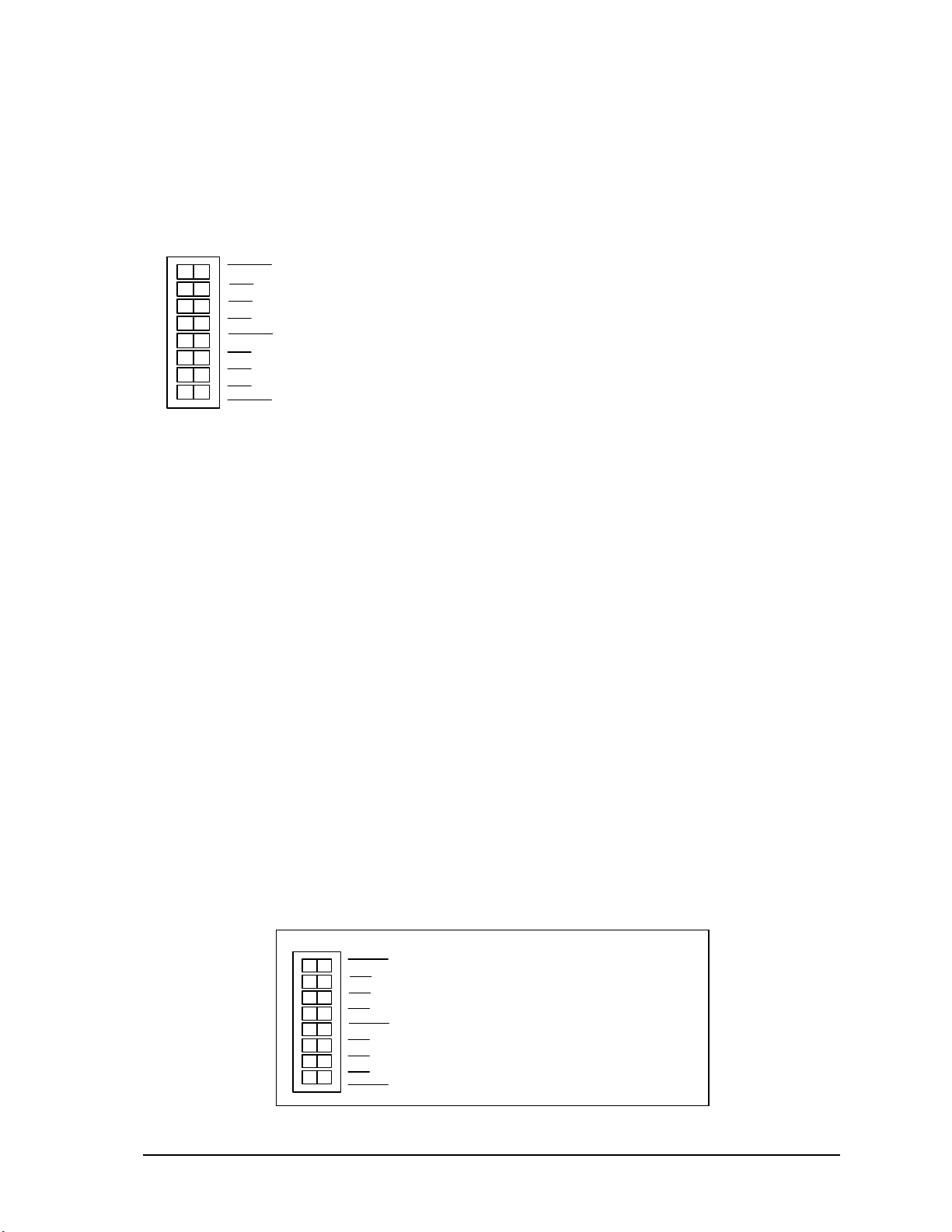
The SCADAPackl32 SCADAPack 32P SW1 is an eight position DIP switch. The first seven
switches on SW1 are used to configure digital / counter input filtering and analog input and output
ranges. SW1 is shown in the following diagram. Refer to 3.1.1-5232 Controller Board Field Wiring
Connectors for the location of SW1 on the SCADAPack 32P SCADAPack 32P.
SW 1
•
1
2
Options
3
4
0
1
Filters
2
not used
Configuration switches can be changed with the power applied. Configuration changes take effect
immediately.
To select configuration switch functions:
• Remove the module cover and locate the configuration switches. See section 3.1-Field Wiring
Connections for SW1 location.
• Slide the switch actuator to the right side of the switch to enable the switch function.
SW1-1 Option 1 Available for application programs.
•
SW1-2 Option 2 Available for application programs.
•
SW1-3 Option 3 Available for application programs.
•
SW1-4 Option 4 Available for application programs.
•
SW 1-5 Filter 0 DIN/Counters input 0 filtering.
•
SW 1-6 Filter 1 DIN/Counters input 1 filtering.
•
SW 1-7 Filter 2 DIN/Counters input 2 filtering.
•
SW1-8 Not Used
C
• Slide the switch actuator to the left side of the switch to disable the switch function.
6.7.1 Digital Input Filters
Each of the three digital / counter (DIN/Counters) inputs on the SCADAPack 32P SCADAPack 32P
can be filtered. Filtering limits the maximum digital input or counter frequency to approximately
30Hz.
• Use a filter for 50 or 60Hz digital inputs and for low speed counting applications that experience
problems due to contact bounce.
• Do not use filtering for high speed counting applications.
SCADAPack 32P SCADAPack 32P SW1, switches Filter 0, Filter 1 and Filter 2 switches control the
input filter functions.
• Filter 0 for DIN/Counters input 0.
• Filter 1 for DIN/Counters input 1.
• Filter 2 for DIN/Counters input 2.
SW 1
1
2
3
4
0
1
2
not used
Options
Filters
•
To enable a filter, slide the Filter 0, Filter 1
or Filter 2 actuator to the right side of the
switch (closed).
•
To disable a filter, slide the Filter 0, Filter 1
or Filter 2 actuator to the left side of the
switch (closed).
SCADAPack 32P Controller Hardware Manual
May 26, 2006
33
Page 35
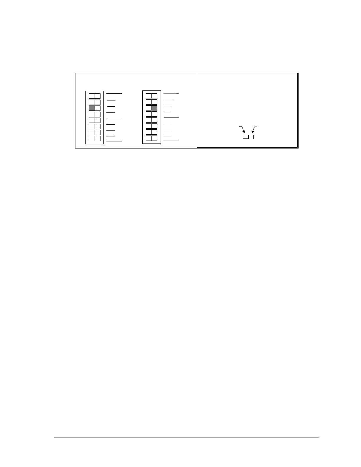
6.7.2 Line Frequency Selection
p
The SCADAPack 32P Option Switch 3 selects the line frequency option. The diagram below shows
the switch settings for selecting the line frequency.
60 Hz Operation
SW 1
1
2
3
4
0
1
2
not used
Options
Filters
50 Hz O
SW 1
eration
1
2
3
4
0
1
2
not used
Options
Filters
How to Set the Frequency Switch :
•
Determine the desired range.
•
Slide the actuator to the side of
the switch shown in gray.
This side for
60 Hz.
This side for
50Hz.
SCADAPack 32P Controller Hardware Manual
May 26, 2006
34
Page 36

7 Maintenance
The SCADAPack 32P controllers require little maintenance. The 5V power LED indicates the status
of the 5V supply. If the LED is off, and the SCADAPack 32P controller is powered using the
integrated power supply, on board fuse F1 or F2 may require replacing. If the LED is off, and the
SCADAPack 32P controller is powered using a 5103 power supply fuse F1 (5V) or F2 (24V) on the
5103 may require replacing. If the program is lost during power outages, the lithium battery may
require replacement.
The analog input and output circuitry is calibrated at the factory and does not require periodic
calibration. Calibration may be necessary if the module has been repaired as a result of damage.
If the SCADAPack 32P Controller is not functioning correctly, contact Control Microsystems
Technical Support for information on returning the SCADAPack 32P Controller for repair.
WARNING: Do not connect or disconnect any field wiring, including the wiring to the RS-232
ports, unless the power is off or the area is know to be non-hazardous.
7.1 Fuses
Two 1.0 Amp slow-blow fuses protects the power supply. The fuse is mounted under the cover. Fuse
F1 protects the SCADAPack 32P when powered from the AC/DC Power Input. Fuse F2 protects the
SCADAPack 32P controller when powered from the DC Power Input. Refer to section 3.1-Field
Wiring Connections for their location.
CAUTION: Remove power before servicing unit.
Always replace a defective fuse with a fuse of the same rating. Under no circumstances should a fuse
be bypassed or replaced with a fuse of a higher rating.
The fuse is a Littelfuse Nano-SMF. Littelfuse part number LF R452 001. Control Microsystems part
number 200072.
In all cases investigate and correct the cause of the fuse failure before replacement. Common causes
of fuse failure are short circuits and excessive input voltages.
Refer to sections 3.2.4-Recommended DC Power Supply Configuration and 3.2.5-Recommended
24VDC Battery Supply Configuration for recommendations on reducing the DC inrush current if
fuse blowing is being experience in DC power supply applications.
7.2 Lithium Battery
A small lithium battery powers the CMOS memory and real-time clock when input power is
removed. The voltage of a functioning battery should be greater than 3.0V. An application program
can monitor this voltage. Refer to the programming manual for details.
The battery should not require replacement under normal conditions. The shelf life of the battery is
10 years. The battery is rated to maintain the real-time clock and RAM data for two years with the
power off. Accidental shorting or extreme temperatures may damage the battery.
7.2.1 Battery Replacement Procedure
The battery is plugged into the circuit board and secured with a tie-wrap. If necessary it can be
replaced with an identical battery available from Control Microsystems.
• Save the existing program running in the SCADAPack, if applicable.
• Remove power from the SCADAPack.
SCADAPack 32P Controller Hardware Manual
May 26, 2006
35
Page 37

• Remove the SCADAPack top cover and locate the battery. It is found at the far right side of the
circuit board.
• The battery tie wrapped in place at the factory. This is to ensure the battery does not become
disconnected during shipment. Cut the tie wrap using wire cutters.
• Remove the battery by gently lifting it straight up from the circuit board. The battery has two
pins that mate with two sockets on the circuit board.
• Replace the battery. A replacement tie wrap is not necessary.
• Cold boot the controller. (Refer to section 6.3-Cold Boot Mode section in of this manual for the
Cold Boot procedure.)
Warning: If a cold boot is not done the behavior of the controller is unpredictable.
• The controller may now be programmed.
SCADAPack 32P Controller Hardware Manual
May 26, 2006
36
Page 38
8 Specifications
Disclaimer: Control Microsystems reserves the right to change product specifications without
notice. For more information visit
8.1 General
www.controlmicrosystems.com .
I/O Terminations
6,8,9 and 10 pole, removable terminal blocks.
12 to 22 AWG
15A contacts
Dimensions
8.40 inch (213mm) wide
6.13 inch (155mm) high
1.75 inch (44mm) deep
Packaging
Environment
corrosion resistant zinc plated steel with black enamel paint
5% RH to 95% RH, non-condensing
o
–40
C to 70oC
o
–40
F to 158oF
8.2 SCADAPack 32P Controller
Processor
Memory
Non-volatile
RAM
Clock calendar
Internal
temperature
Lithium battery
monitor
Hitachi SH-3 32-bit CMOS microcontroller
120 MHz. clock
4Mbytes Flash
8Mbytes SDRAM
1024kBytes CMOS RAM
CMOS RAM with lithium battery retains contents for 2 years
with no power
±1 minute/month at 25°C
+1/–3 minutes/month 0 to 50°C
Measurement range -40°C to 75°C. Accuracy ±5°C.
Measurement range -40°F to 167°F. Accuracy ±9°F.
Accuracy ±0.2V.
8.3 Communications
Communication
Ports
Communication
Ports
Baud Rates
(COM1, COM2,
COM4)
SCADAPack 32P Controller Hardware Manual
May 26, 2006
2 RS-232 serial ports (COM2, COM4)
Data Terminal Equipment (DTE)
8 pin modular jack
One serial port configurable RS-232 or RS-485 (COM1)
RS-232:
Data Terminal Equipment (DTE)
8 pin modular jack
RS-485:
2 wire half duplex
4 wire full or half duplex
optional termination resistors
300, 600, 1200, 2400, 4800, 9600, 19200, 38400, 57600 and
115200.
37
Page 39
Parity
Word Length
Stop Bits
Duplex (COM1,
none, even, or odd
7 or 8 bits
1 or 2 bits
full or half with RTS/CTS control
COM2, COM 4)
Cable Length
RS-232 –maximum 50 ft (15.2 m)
RS-485 –maximum 4000 ft (1200 m)
Ethernet
Termination
RJ-45 modular connector
10BaseT (twisted pair)
10M bits per second.
Protocol
TeleBUS (compatible with Modbus RTU and Modbus ASCII)
Protocol Modes
slave, master, master/slave, store and forward
8.4 Visual Indicators
COM1,COM2,
COM4
received data (RxD) LED
transmitted data (TxD) LED
clear to send (CTS) LED
data carrier detect (DCD) LED
Ethernet LAN
Ethernet network receive or transmit data LAN LED
Ethernet port connected to a network LINK LED
I/O module LED power status LED
Status LED (shows functional status)
5V power LED (LED power not applicable)
Run LED
Forced I/O LED
Counter Inputs 0, 1, 2 and 3 LEDs
Push-button
LED power toggle
8.5 Power Supply
Power Input
AC/DC PWR IN
DC power Input
DC PWR
5 Volt Power
Output
DC power
Output
16Vrms applied
Efficiency
Transient
Protection
16Vrms ±20%
13 to 24Vdc nominal
30Vdc maximum
30V maximum
10.7V typical turn on
9V typical turn off
5V at 1.3A capacity
5V at 500 mA required by SCADAPack 32P
20-24V with 1.0Vp-p maximum ripple.
300mA available at 5V/0.5A, de-rate linearly to 100mA
available at 5V/1.3A
80%, 12V on DC PWR input
Transient: 2.5kV surge withstand capability as per ANSI/IEEE
C37.90.1-1989
SCADAPack 32P Controller Hardware Manual
May 26, 2006
38
Page 40
8.6 I/O Capacity
(
5000 Series I/O
Expansion
Capacity
Maximum 40 I/O modules with a further limitation of 16
modules of any one type.
512 digital inputs using 32 point digital output modules
512 digital inputs using 32 point digital input modules
128 analog inputs using 8 point analog input modules
64 analog outputs using 4 point analog output modules
32 counter inputs using 4 point counter input modules
Example: 16 of the 32 point digital output modules + 16 of
the 32 point digital input modules + 8 of the 8 point analog
input modules would yield an expansion of 1088 I/O points.
8.7 Digital Inputs
Input Points
Digital Input,
Counter
Counter Input
Frequency
(Counter 0, 1, 2)
Counter Input
Frequency
(Counter 3)
Transient
Protection
4 Digital Input/Counter, opto coupler isolation
24Vrms/30V maximum input
10Vrms/10V minimum ON input
2V maximum OFF input
Typical threshold voltage is 4 to 6V
Typical input hysteresis 1.0V
Typical input current 2.5mA at 10V
7mA at 24V
5 kHz maximum with filter OFF
30 Hz maximum with filter ON
500 Hz maximum
Transient: 2.5kV surge withstand capability as per ANSI/IEEE
C37.90.1-1989
8.8 Digital Outputs
Status Output
Transient
Protection
Opto coupler open collector transistor
30V, 60mA
opens on fault
Transient: 2.5kV surge withstand capability as per ANSI/IEEE
C37.90.1-1989
8.9 Approvals and Certifications
Safety
Digital
Emissions
Immunity
Declaration
SCADAPack 32P Controller Hardware Manual
May 26, 2006
Non-Incendive Electrical Equipment for Use in Class I, Division
2 Groups A, B, C and D Hazardous Locations.
FCC Part 15, Subpart B, Class A Verification
EN50081-2: 1993 Electromagnetic Compatibility Generic
Emission Standard Part2: Industrial Environment
EN61000-6-2: 1999 Electromagnetic Compatibility Generic
Standards Immunity for Industrial Environments
This product conforms to the above Emissions and Immunity
Standards and therefore conforms with the requirements of
Council Directive 89/336/EEC
as amended) relating to
39
Page 41

electromagnetic compatibility.
The Low Voltage Directive is not applicable to this product.
SCADAPack 32P Controller Hardware Manual
May 26, 2006
40
 Loading...