


INSTALLATION AND OPERATIONS MANUAL
Worktop and Undercounters
Refrigerated Bases, Pizza Prep Tables & Griddle Stands
Refrigerators & Freezers
Please fill in the following information for your NEW unit, carefully read the instructions in this manual and file it for future reference.
MODEL NO.
SERIAL NO.
PURCHASED FROM
INSTALL DATE
1-800-523-7138
Continental Refrigerator
A Division of National Refrigeration & Air Conditioning Products, Inc.
539 Dunksferry Road Bensalem, PA 19020-5908 P 215-244-1400
F 215-244-9579 www.continentalrefrigerator.com

TABLE OF CONTENTS
|
Page |
Receiving Your New Model.............................................................................................................. |
3 |
General Information and Important Operating Facts................................................................................ |
3 |
Uncrating Your New Model.............................................................................................................. |
3 |
Installation and Location................................................................................................................. |
4 |
Ventilation.............................................................................................................................................................. |
4 |
Floor Loads............................................................................................................................................................. |
5 |
Installing Casters and Leveling............................................................................................................................... |
5 |
Caster Support Plates............................................................................................................................................. |
5 |
Installing Legs and Leveling................................................................................................................................... |
6 |
Condensate Removal.............................................................................................................................................. |
6 |
Removal of Doors................................................................................................................................................... |
7 |
Door Adjustment.................................................................................................................................................... |
8 |
Mounting Self-Closing Hinge Mechanism.............................................................................................................. |
8 |
Removal and Replacement of Hinge Mechanism................................................................................................... |
8 |
Re-Hinging Doors................................................................................................................................................... |
9 |
Removal of Drawers and Drawer Adjustments....................................................................................................... |
9 |
Removing Lid and Hood (Pizza Prep and Sandwich Units Only)............................................................................ |
9 |
Initial Cleaning Procedure.............................................................................................................. |
10 |
Start-Up Procedure....................................................................................................................... |
10 |
Electrical Connections............................................................................................................................................ |
10 |
115 Volt, 60 Hz, 1 Phase Connection....................................................................................................... |
11 |
115/208-230 Volt, 60 Hz, 1 Phase Connection........................................................................................ |
11 |
Special Voltage Connections.................................................................................................................... |
11 |
Start-Up Checklist.................................................................................................................................................. |
11 |
Remote Applications.............................................................................................................................................. |
11 |
Operation.................................................................................................................................. |
11 |
Thermometer and Adjustment............................................................................................................................... |
11 |
Refrigeration System and Adjustment................................................................................................................... |
12 |
CPT Temperature Control Adjustments................................................................................................................. |
12 |
Pizza Prep Table Operation....................................................................................................................... |
12 |
Pizza Rail System Switch......................................................................................................................... |
12 |
Pizza Prep Temperature Adjustment - Bottom Storage Compartment..................................................... |
12 |
Pizza Prep Temperature Adjustment - Coldwall Rail................................................................................ |
12 |
Evaporator Assembly............................................................................................................................................. |
13 |
Freezer System and Adjustment............................................................................................................................ |
13 |
Defrost Operation...................................................................................................................................... |
14 |
Interior Accessories............................................................................................................................................... |
14 |
Shelving Installation.................................................................................................................................. |
14 |
Maintenance.............................................................................................................................. |
15 |
Periodic Cleaning Procedure................................................................................................................................. |
15 |
General Preventative Maintenance......................................................................................................................... |
15 |
Parts and Service......................................................................................................................... |
16 |
Placing a Service Call............................................................................................................................................ |
16 |
Obtaining Replacement Parts Under Warranty....................................................................................................... |
16 |
Obtaining Replacement Compressor Under Warranty............................................................................................ |
16 |
Optional Accessories.................................................................................................................... |
17 |
Installing Overshelf or Double-Overshelf............................................................................................................... |
17 |
Installing Front Breather Kit................................................................................................................................... |
17 |
Installing Drawer Cage........................................................................................................................................... |
18 |
Mounting Caster Support Plates............................................................................................................................ |
19 |
Installing Electric Condensate Vaporizer................................................................................................................ |
20 |
Dial Thermometer and Calibration......................................................................................................................... |
21 |
Digital Thermometer and Calibration..................................................................................................................... |
21 |
Remote Set-Up and Installation Guidelines............................................................................................................ |
21 |
Troubleshooting and Servicing Guide................................................................................................. |
24 |
Wiring Diagrams......................................................................................................................... |
26 |
Limited Extended Protection Warranty................................................................................................ |
30 |
OPERATIONS MANUAL
REFRIGERATED BASES, PIZZA PREP TABLES & GRIDDLE STANDS
RECEIVING YOUR NEW MODEL
Congratulations on your purchase of Continental Refrigerator superior foodservice equipment! When your shipment arrives, thoroughly examine the packaging for any punctures, dents, or signs of rough handling. It is in your best interest to partially remove or open the shipping container in order to examine the contents for any missing accessories, or concealed damage which may have occurred during shipment. If the cabinet is damaged, it must be noted on the carrier’s delivery slip or bill of lading (see “Filing a Damage Claim” under “Warranty” section).
GENERAL INFORMATION AND
IMPORTANT OPERATING FACTS
This manual has been compiled to aid in the installation, operation and maintenance of your new equipment. Please take the time to read it and familiarize yourself with your equipment and its operation, to enjoy optimum performance.
Continental Refrigerator offers a variety of accessories for your model (see “Optional Accessories” section towards the back of this manual or contact your dealer for more information).
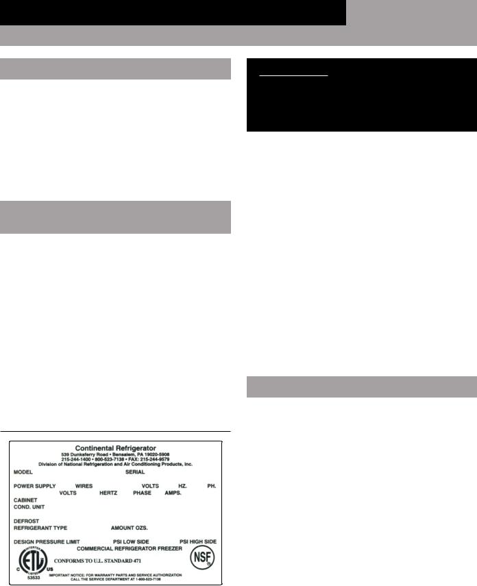
SERIAL DATA TAG
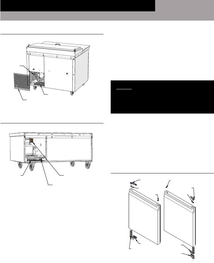
A serialized data tag is permanently attached to the inside righthand wall of your unit. (see Figure 1). In addition to identifying the specific product, this label provides important information regarding electrical requirements and refrigeration charge, as well as agency listings and factory contacts.
FIGURE 1: Data Tag
IMPORTANT NOTE: The model and serial number should be noted on the front cover of this manual, in the spaces provided. If parts or service are ever needed for your unit, this information will be required to verify warranty status and to properly identify any parts that may be needed.
All cabinets must be given sufficient time to reach normal operating temperature before placing any food inside cabinet or pans (if equipped). For refrigerators, approximately 1 hour of operation is required to lower the cabinet and pan temperature to 40°F (4°C). During pull-down of open top models, pans should be in place and top lid should be kept closed. Freezers require approximately 2 hours of operation to lower the cabinet temperature to 0°F (-18°C) (see “Operation” section for further information).
Prior to factory shipping, all products are performance-run tested for a minimum of 12 hours providing a highly sophisticated temperature recording exclusive to each individual cabinet. This recording is supplied within this manual packet. A final evaluation, including analysis of cabinet performance, leak check, vibration, noise level and visual examination is made by a qualified quality control team to assure a superior product. The carrier signs to this effect when they accept the product for shipping. To insure the maximum in safety and sanitation, all models are listed under the applicable of Underwriters Laboratories and National Sanitation Foundation standards.
UNCRATING YOUR NEW MODEL
The shipping container should remain on your cabinet to protect against dents or scratches while transporting to the actual set-up location. Remove the shipping container only at the last possible moment by using a pry bar to take out all the staples from around the bottom of the crate. Slide the cardboard carton up and off the unit, being careful not to rub against the cabinet. Remove any accessories or boxes on the skid or in the cabinet.
Four (4) bolts secure the cabinet to the wooden skid. The bolts are located at each end on the underside of the skid. In order to remove these bolts, tilt the cabinet backwards and place wooden blocks at each end in order to hold it in its tilted position. Using a ¾” socket or open end wrench, remove the bolts and carefully slide the cabinet off of the skid. After skid removal, the cabinet should never be moved without dollies or rollers to avoid damage to the cabinet bottom or floor.
|
|
OPERATIONS MANUAL |
3 |
|
|
REFRIGERATED BASES, PIZZA PREP TABLES & GRIDDLE STANDS
IMPORTANT NOTE: Do not under any circumstances, lay your new model on its front or sides. For a brief period of time, you may lay the cabinet on its back, but only when its properly blocked so as not to crush the louvered venting panel and also to allow provision for your hands, in order to set it in its upright position without damaging the cabinet. Do not plug in and operate model for at least three (3) hours after cabinet is set upright from being on its back as this can damage the compressor.
INSTALLATION AND LOCATION
Before moving the cabinet to its final point of installation, measure all doorways or passages to assure clearance. If additional clearance is needed, you can remove the cabinet doors (see “Removal of Doors and Door Adjustment”) and lids (when equipped) (see “Removing Lid and Hood”).
VENTILATION
The final location site of your air cooled refrigerator or freezer must provide a large quantity of cool, clean air. All refrigeration systems operate most efficiently and trouble-free with cool, dry air circulation. Avoid locations near heat and moisture generating equipment including ovens, cooking ranges, fryers, dishwashers, steam kettles, etc., or in direct sunlight (where temperatures can exceed 100°F). Do not select a location in an unheated room or area where temperatures may drop below 55°F. Air supply to the condensing unit is equally importantRestricting the air places an excessive heat load on the condensing unit and adversely effect its operation.
NOTE: Heat-generating equipment (griddles, broilers, toasters, etc.) should have a minimum 4” clearance underneath, to the top of your refrigerated cabinet. Temperature at cabinet surface should not exceed 100F, or damage can occur to your cabinet which is not covered under warranty. If needed, a heat shield must be used to protect your cabinet.
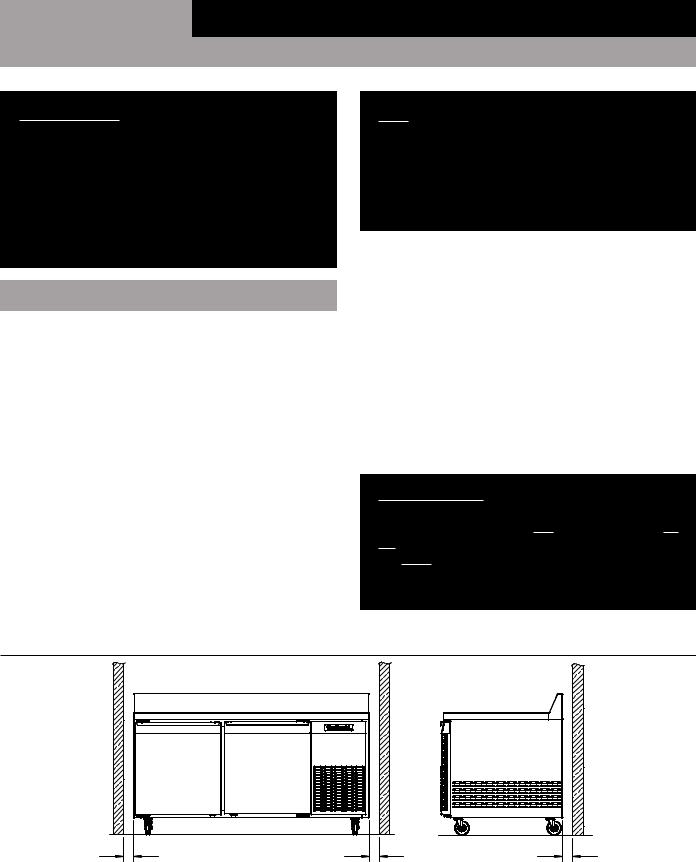
For optimum performance, all models (except for Undercounters and Front Breathing cabinets) should be installed on casters or legs (see “Installing Casters” or Installing Legs”) with a minimum 3” clearance on each side and the back of the cabinet (see Figure 2). If any of the above conditions can not be achieved, the installer should provide special venting or air supply ducts, or a Front-Breather Kit (see “Optional Accessories”) can be ordered by contacting the factory.
Undercounter and Front Breathing models do not require any clearance around the the sides or back of the cabinet, since they take in and exhaust air under the cabinet and through the front grill, under the door. The air flow under the cabinet and through the front grill cannot be restricted.
IMPORTANT NOTE: For optimum performance, your cabinet should be located where an unrestricted air supply can circulate underneath and behind the cabinet. Do not obstruct the grill in the rear of the cabinet in any way, and never place or store anything inside the compressor compartment. These rules are essential for maximum cooling capacity and long life of your unit.
FIGURE 2: Minimum Clearance Dimensions for Optimum Conditions (Except for Undercounter & Front Breathing Models)
3" |
3" |
3" |
MINIMUM |
MINIMUM |
MINIMUM |
CLEARANCE |
CLEARANCE |
CLEARANCE |
|
|
4 |
OPERATIONS MANUAL |
|
|
REFRIGERATED BASES, PIZZA PREP TABLES & GRIDDLE STANDS
FLOOR LOADS
The floor at the final location site must be level, free of vibration and strong enough to support the total combined weights of your new model plus the maximum product load which might be placed into it. Keep in mind that all the weight is concentrated at the caster or leg locations. To estimate the possible product weight, assume that each cubic foot of storage space weighs approximately 35 pounds. Multiply 35 pounds by the amount of cubic feet in the cabinet to obtain the product load weight.
For example, a 20 cubic foot refrigerator can hold approximately 700 pounds of product (35 x 20). Assuming the cabinet itself weighs 300 pounds, the total combined weight of cabinet and product is approximately 1000 pounds. Therefore, the floor in this example must be able to support up to 1000 pounds.
NOTE: Any equipment placed on your cabinet must be included in the floor load circulation. Do NOT overload the top of your cabinet by placing extremely heavy equipment on it, or damage can occur, which is NOT covered under Warranty. Griddle Stand models are designed to support equipment such as griddles or broilers. Consult the factory for information on the weight load capacity for your specific cabinet.
INSTALLING CASTERS AND LEVELING
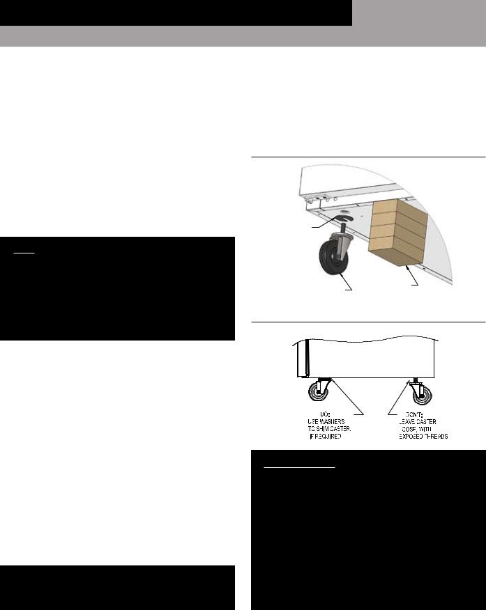
If your new unit is supplied with swivel casters, they will be packed in the accessory box that came with your cabinet. Casters should be installed only when the cabinet is close to it’s final installation site. To install casters on your new model, place wooden blocks along the back, at each end. Tilt the cabinet back, using the wood blocks to help hold the cabinet in its tilted position. Locate the large threaded holes on the bottom of the cabinet and screw the threaded caster studs into the mounting holes, closest to the front of the unit. Repeat this procedure by tilting the cabinet in the opposite direction and installing the remaining casters. Make sure the casters are tightened extremely well (see Figure 3 & 3A). If the casters are not installed tightly, the cabinet will be unstable and may sway or rock, which can damage the cabinet.
If the height of a caster needs to be raised, shims must be installed under the casters which need leveling. Extra large washers, available at most hardware or furniture stores, can be used to shim casters, or contact the factory for caster shims.
Do not level casters by unscrewing them and leaving them loose. This will damage the cabinet and threaded holes, voiding your warranty.
CASTER SUPPORT PLATES (Griddle Stands)
For maximum weight capacity, all Griddle Stand models are shipped with caster support plates, packed inside the accessory carton of your cabinet (see “Mounting Caster Support Plates” under the “Optional Accessories” section) of this manual for more information.
FIGURE 3: Installing Casters
OPTIONAL CASTER SHIM (CM1-2476)
BLOCKS
CASTER
FIGURE 3A: Casters Must Be Tight to Cabinet Bottom
IMPORTANT NOTE: It is extremely important that your cabinet is perfectly level for proper operation. If it is not level, the following adverse conditions may occur:
1.The door(s) will not be properly aligned and consequently will not provide a good seal.
2.Your unit may run excessively.
3.An excessive amount of ice will accumulate inside the cabinet, around the door opening(s) and on the finned evaporator coil. If allowed to continue, ice will eventually block the coil and the unit will fail. This can result in the loss of all food stored in the cabinet.
4.Defrost water will fail to drain properly and will overflow the evaporator coil drain pan and into the cabinet of both refrigerator and freezer models.
|
|
OPERATIONS MANUAL |
5 |
|
|
REFRIGERATED BASES, PIZZA PREP TABLES & GRIDDLE STANDS
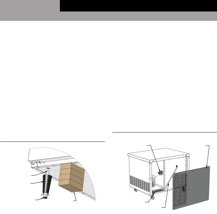
INSTALLING LEGS AND LEVELING
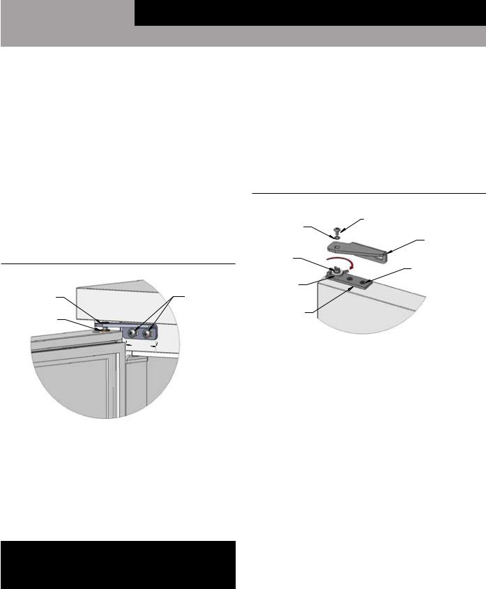
If your new unit is supplied with adjustable legs Legs, they will be packed in the accessory carton in the cabinet. Your cabinet will have either four (4) or (6) threaded mounting holes on the bottom of the cabinet (see Figure 4). In order to install the legs, carefully tip the cabinet back, adding four (4) 2” wood blocks underneath, and simply screw the threaded leg studs into the case bottom front leg holes. Repeat this procedure by tilting the cabinet in the opposite direction and install the remaining legs. Make sure the legs are tightened extremely well or the entire model will sway or rock with each opening or closing of the doors, possibly causing damage to the case bottom. This procedure should be performed close to the final installation site and allow access to the rear of the cabinet for condensate evaporator installation (see “Installing Condensate Evaporator” under “Installation and Location” section).
To assure your cabinet is level, all legs are equipped with bullettype leveling bolts. These bolts can be turned by hand or by wrench, clockwise or counterclockwise to level the cabinet.
FIGURE 4: Leg Installation
CONDENSATE REMOVAL
No floor drains or plumbing connections are required since all models use an automatic condensate water evaporating system (see Figure 5, 5A & 5B). All models utilize a unique hot air condensate water evaporating system which is completely self-contained and no further assembly or maintenance is required. In some adverse conditions such as high ambient temperature, high humidity, extremely heavy usage, frequent loading for prolonged periods of time, or heavy pan loading, the amount of condensate water generated could overflow the pan. If this occurs, the plastic drain tube from the cabinet can be diverted directly to a floor drain, bypassing the condensate pan. Alternatively, an optional electric condensate vaporizer may be purchased as an accessory. An electric condensate vaporizer is also supplied with all remote models. To install the optional condensate vaporizer, follow the steps for (“Installing Electric
Condensate Vaporizer” in the “Optional Accessories” section) towards the back of this manual.
FIGURE 5: CPT/CRB Components (Back View)
DEFROST TIMER |
REMOVE SCREWS FROM |
TOP OF BACK PANEL AND |
|
(FREEZERS ONLY) |
LIFT OFF TO REMOVE |
THREADED
END
LEG |
|
|
TURN FOOT CLOCKWISE |
|
|
TO REDUCE HEIGHT, OR |
|
|
COUNTERCLOCKWISE |
|
|
TO INCREASE HEIGHT. |
BLOCKS |
DRAIN PAN |
|
DRAIN LINE
|
|
6 |
OPERATIONS MANUAL |
|
|
REFRIGERATED BASES, PIZZA PREP TABLES & GRIDDLE STANDS
FIGURE 5A: CPA Components (Back View)
DRAIN
LINE
DRAIN PAN
REMOVE SCREWS FROM
ACCESS PANEL AND
LIFT OFF TO REMOVE.
FIGURE 5B: Griddle Stand Components (Back View)
DRAIN PAN |
TEMPERATURE CONTROL |
|
(BEHIND FRONT GRILL) |
||
|
||
|
DRAIN TUBE |
REMOVAL OF DOORS
During installation, it may become necessary to remove the cabinet doors to facilitate passage through narrow doorways or hallways. Depending on the age of your cabinet, the springloaded hinge cartridge is located either on the top or the bottom of the door. To remove a door, verify the location of the springloaded cartridge (see Figure 6). Swing the door to the open position (90°) and remove the mounting screws securing the the hinge cartridge bracket to the cabinet (either above or below the door).
CAUTION: THE HINGE CARTRIDGE IS SPRING LOADED AND MAY SNAP TOWARDS THE DOOR WHEN THE MOUNTING SCREWS ARE REMOVED. BE SURE
TO HOLD DOOR FULLY OPEN BEFORE REMOVING MOUNTING SCREWS.
For doors with the spring cartridge on the bottom: after removing the bracket mounting screws below the door, carefully lower the door straight down, and free of the pivot pin bracket above the door. (For doors with the spring cartridge on top: after removing the bracket mounting screws above the door, carefully lift the door straight up, and off the pivot pin bracket below the door).
FIGURE 6: Door Hinge Components
(Spring Cartridge at Bottom)
PIVOT PIN |
PLUG BUTTON |
BRACKET |
PIVOT PIN |
|
|
BUSHING |
BRACKET |
PLUG |
BUSHING |
BUTTON |
LEFT-HAND
DOOR RIGHT-HAND DOOR
HINGE |
HINGE |
BRACKET |
CARTRIDGE |
HINGE |
HINGE |
CARTRIDGE |
|
|
BRACKET |
|
|
OPERATIONS MANUAL |
7 |
|
|
REFRIGERATED BASES, PIZZA PREP TABLES & GRIDDLE STANDS
DOOR ADJUSTMENT
All doors are aligned at the factory, however vibration during transit may cause them to shift and realignment may be necessary. If the door(s) require realignment, proceed as follows
(see Figure 7):
1.Open the door (90°) and loosen, but do not remove the mounting screws securing both the top and bottom hinge brackets to the cabinet.
2.Adjust the door to the desired position by hand or by tapping on the edge with a rubber mallet.
3.Securely tighten all of the mounting screws, above and below the door.
4.Check the door alignment and repeat adjustment if necessary.
FIGURE 7: Hinge Adjustment
PIVOT PIN |
CABINET TOP |
BRACKET |
BRACKET |
|
MOUNTING |
BUSHING |
SCREWS |
|
|
|
ADJUST |
LEFT-HAND DOOR |
|
(SPRING CARTRIDGE |
|
AT BOTTOM) |
|
MOUNTING SELF-CLOSING HINGE MECHANISM
(For Doors with Hinge Cartridge on Bottom)
For proper operation of the self-closing doors on all models, the hinge mechanism must be mounted to apply tension in the proper direction (see Figure 8). When the hinge is moved to the open-door position, it should be tension-free. However, when the hinge is moved back into the closed position, it should snap back.
CAUTION SHOULD BE TAKEN WHEN CHECKING THE SPRING LOADING AS THE HINGE COULD SNAP BACK ON FINGERS.
If the hinge does not work as described, follow these steps:
1.Using the hinge upside down as a wrench, turn the mechanism in the door 180° in either direction. The mechanism should snap to a null point.
2.Remount the hinge as shown in Figure 6.
3.Repeat the test procedure as described above until the hinge snaps back when it is moved from the open-door position towards the closed-door position.
FIGURE 8: Spring Loaded Hinge Mounting
LOCKWASHER |
BRACKET ATTACHMENT |
|
SCREW |
|
|
|
|
CARTRIDGE |
SPRING-LOADED |
|
BRACKET |
MECHANISM |
|
|
|
TIGHTEN |
CARTRIDGE MOUNTING |
SCREWS (2)
SPRING CLIP
BOTTOM
OF DOOR
SPRING-LOADED
CARTRIDGE
HINGE CARTRIDGE IN BOTTOM OF LEFT-HAND DOOR (CARTRIDGE IN BOTTOM OF LEFT-HAND DOOR OPPOSITE)
REMOVAL AND REPLACEMENT OF HINGE MECHANISM
To remove the hinge mechanism from the door, remove the door from the cabinet as explained previously. As shown in Figure 8, remove the hinge plate from the hinge mechanism by removing the hinge pin screw. Also remove the horseshoe spring. Reinstall the hinge pin screw only partially leaving about 1/8” of exposed screw threads. Now, the hinge mechanism mounting screws can be removed thus allowing the mechanism to be removed by pulling on the hinge pin screw. If the mechanism does not readily slide out of the door, slide a claw hammer or forked prybar under the hinge pin screw head and using a block of wood for leverage, lift the entire mechanism out of the door. To install the new hinge mechanism, reverse the above procedure.
|
|
8 |
OPERATIONS MANUAL |
|
|
REFRIGERATED BASES, PIZZA PREP TABLES & GRIDDLE STANDS
RE-HINGING DOORS
IMPORTANT NOTE: The doors are field reversible, but different hinge brackets are required. HAVE YOUR
MODEL SERIAL NUMBER READY AND CONTACT THE FACTORY FOR THE PARTS NEEDED FOR YOUR UNIT.
Detach the door and remove the hinge mechanism, as previously described. Remove the hinge from the cabinet by loosening the (2) mounting screws. Remove the plug button and bushing from the door. A flat-blade screwdriver or putty knife may be used to carefully pry them out, if required.
To re-assemble the reverse-hinged door, select the proper
“opposite-hand” top and bottom hinge brackets and cartridge insert (see Figure 6 for parts identification). Follow the steps above, in reverse order.
REMOVAL OF DRAWERS AND DRAWER ADJUSTMENTS
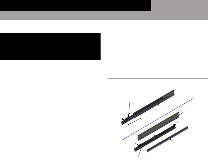
To remove the drawers from the cabinet, slide each drawer out until it stops. Unhook the stop clip at the front of the left and right-hand drawer slide (see Figure 9) by pushing the clip forward and pressing down on the top back edge as shown. Lift the drawer slightly as you pull it the rest of the way out. The center member, with the wheels attached, will remain in the cabinet. To remove a drawer center member for cleaning or maintenance, pull it out and push up on the release lever at the back, as shown.
To install a drawer, identify the correct parts and orient the center members so the plastic clips are in the front and at the top. Insert one of the center members into the front of the correct cabinet member (which is permanently attached to the inside of the cabinet) and slide it in, until it stops. Push up on the release lever (located toward the rear and top of the center member) to allow the center member roll the rest of the way into the cabinet member, in the “drawer closed” position. Repeat for the opposite side center member. Pull each center member out a few inches, press down on the rear of each stop clip, and pull forward so the hook on the front of the clip rotates up, into the “unlocked” position. Lift the drawer body into place, resting the drawer members (the channels welded to the sides of the drawers) on the front wheels of the center member, and slide the drawer into the cabinet. Once the drawer goes in all the way and slides smoothly, open it enough to access the stop clips. Lift the back of each clip and push in at the front, so the hook portion snaps into the “locked” position. The drawers are now
secured, so they cannot accidentally be lifted out of the cabinet. Check that the drawer is properly aligned, rolls smoothly and the drawer gasket seals firmly.
If the drawer fronts needs adjustment (once all drawers are installed and closed), loosen the five screws that hold the drawer front to the drawer body. Move the drawer front into position desired and re-tighten all screws.
FIGURE 9: Drawer Slide
LEFT-HAND SHOWN (RIGHT-HAND OPPOSITE)
SLIDE CLIP FORWARD & PRESS HERE
TO DISENGAGE PUSH UP ON LEVER TO DISENGAGE
CABINET MEMBER
RELEASE LEVER
STOP CLIP |
DRAWER MEMBER |
|
|
|
(EXPLODED VIEW) |
CENTER MEMBER |
|
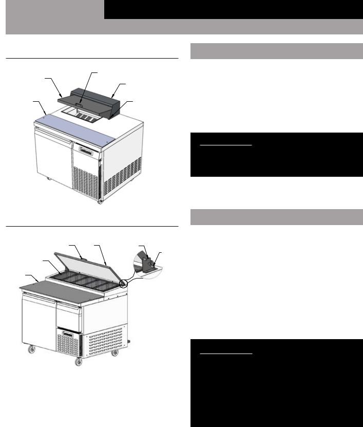
REMOVING LID AND HOOD
(Pizza Prep and Sandwich Top Units Only)
To remove the lid covering the food pan area (see Figure 10), lift it 1/2 way up and carefully push in on the left end at the bottom corner, so the pivot pin comes out of the mating hole in the hood. Swing the end of the lid forward, so it clears the end of the hood. Slide the entire lid to the left, so the pivot pin on the opposite end is free from the hood. If you have an insulated lid, to take out the liner and insulation, remove the screws along the back edge, let the back of the liner drop down and rotate it, so the front edge of the liner disengages from the front edge of the lid. To remove the hood, take out the screws located inside each end and along the back edge.
To remove the lid covering the food pans on Pizza Prep models (see Figure 10A) rotate the lid 1/2 way and lift IT forward and up, so the Hinge Pins disengage from the Hinge Bracket. If you have an insulated lid, see disassembly instructions above.
|
|
OPERATIONS MANUAL |
9 |
|
|
REFRIGERATED BASES, PIZZA PREP TABLES & GRIDDLE STANDS
FIGURE 10: CRB/CPT Sandwich Top Lid Open
|
LID HANDLE |
|
LID |
|
HOOD |
CUTTING |
PIVOT PIN (2) |
BOARD |
FIGURE 10A: CPA & CPT Pan Rail Lid
HANDLE |
LID |
HINGE |
BRACKET |
||
FOOD |
|
PIVOT |
|
PIN |
|
PANS |
|
|
CUTTING |
|
|
BOARD |
|
|
|
|
HINGE DETAIL |
INITIAL CLEANING PROCEDURE
Prior to start-up and before placing any product inside of your new model, the interior of the cabinet should be thoroughly cleaned. Washing with a mild soap and warm water solution is recommended for cleaning the aluminum and stainless steel surfaces of your cabinet. This should be followed by cleaning with a baking soda solution (three (3) tablespoons of baking soda to each quart of warm water). Rinse thoroughly with clear water and dry with a clean, soft cloth.
IMPORTANT NOTE: Never use harsh detergents, cleaners, scouring powders or chemicals when cleaning your model. Failure to dry the interior surfaces after cleaning may result in a streaking or staining of the metal.
Complete cleaning procedures and precautions are listed in the (“Periodic Cleaning Procedure” under the “Maintenance”).
START-UP PROCEDURE
ELECTRICAL CONNECTIONS
To insure proper operation, your new model must be connected to an individual circuit that can supply the full voltage as stated on the cabinet serial data plate. For correct voltage, power draw, and wire accommodations, check the data on the serial data plate located on the inner right wall of your new model. Verify that this information exactly matches the electrical characteristics at the installation location. An electrical wiring diagram, located on the inside compressor compartment rear, next to the electrical console box, should also be consulted during connection. For reference, a copy of each electrical wiring diagram is located towards the back of this manual (see “Wiring Diagrams” section).
IMPORTANT NOTE: The condensing unit supplied with all self-contained models is designed to operate within a range of +/-10% of the voltage indicated on the cabinet serial data plate. Full voltage of the correct rating, on an isolated line, not affected by the operation of other electrical appliances, must be available to the refrigeration unit at all times. Burnout of the compressor due to exceeding high or low voltage limits is easily detected and will void the factory warranty.
|
|
10 |
OPERATIONS MANUAL |
|
|
 Loading...