

CONTINENTAL CONTROL SYSTEMS WattNode BACnet Series, WattNode Revenue Series, WattNode Plus Series, WattNode Logger Series, WNC-3Y FT10 Series Installation Manual
...Page 1
Ground
WHITE
BLACK
ØB CT
ØC CT
ØA CT
ØB
ØC
N
ØA
Common
B+, D1, RxD+/TxD+
EIA-485
PC or BACnet Host
A−, D0, Rx D−/ TxD−
Continental Control Systems LLC
Status
Status
Status
X
C
B
+
A
-
MS/TP
Com
WNCWNC-
W
ATTNODE
®
BAC
NET
-BN
-BN
Neutral
Phase A
Phase B
Phase C
LOAD
WHITE
BLACK
WHITE
BLACK
LINE
Source
Faces
Current
Transformers
3Y-xxx
3D-xxx
WattNode
Series - Service - Interface Options
RWNC = Revenue, third generation
®
BaCNet
and
WattNode® ReveNue
Electric Power Meter
Installation Manual
______ - _______ - ________
3Y-208
3Y-400
3Y-480
3Y-600
3D-240
BN = BACnet
3D-400
3D-480
WNC = Third generation
See website
for options
®
1 Precautions
1.1 Only qualified personnel or licensed electricians should inst all the Wat tN ode me ter. The
mains voltages of 120 to 600 Vac can be lethal!
1.2 Follow all applicable local and national electrical and safety codes.
1.3 T he termina l block sc rews are not insulated.
Do not cont ac t met al too ls to th e sc rew ter mi nals if the circuit is live!
1.4 Veri fy that circui t voltages and cur rents are
within the proper range for the meter model.
1.5 Us e only UL liste d or UL reco gnized curr ent
transformers (CTs) with built-in burden resistors, that generate 0.333 Vac (333 millivolts AC)
at rated cur rent. Do not u se curr ent out put
(ratio) CTs such as 1 a mp or 5 a mp ou tpu t
CTs: they will des troy the me ter and ma y
create a shock hazard.
1.6 Protect the line voltage inputs to the meter with
fuses or c ircuit breake rs (not needed for t he
neutral or ground wires). See 3.3.1 below.
1.7 Equipment must be disconnected from the
HAZARDOUS LIVE voltages before access.
1.8 If the meter is not installed correctly, the safety
protections may be impaired.
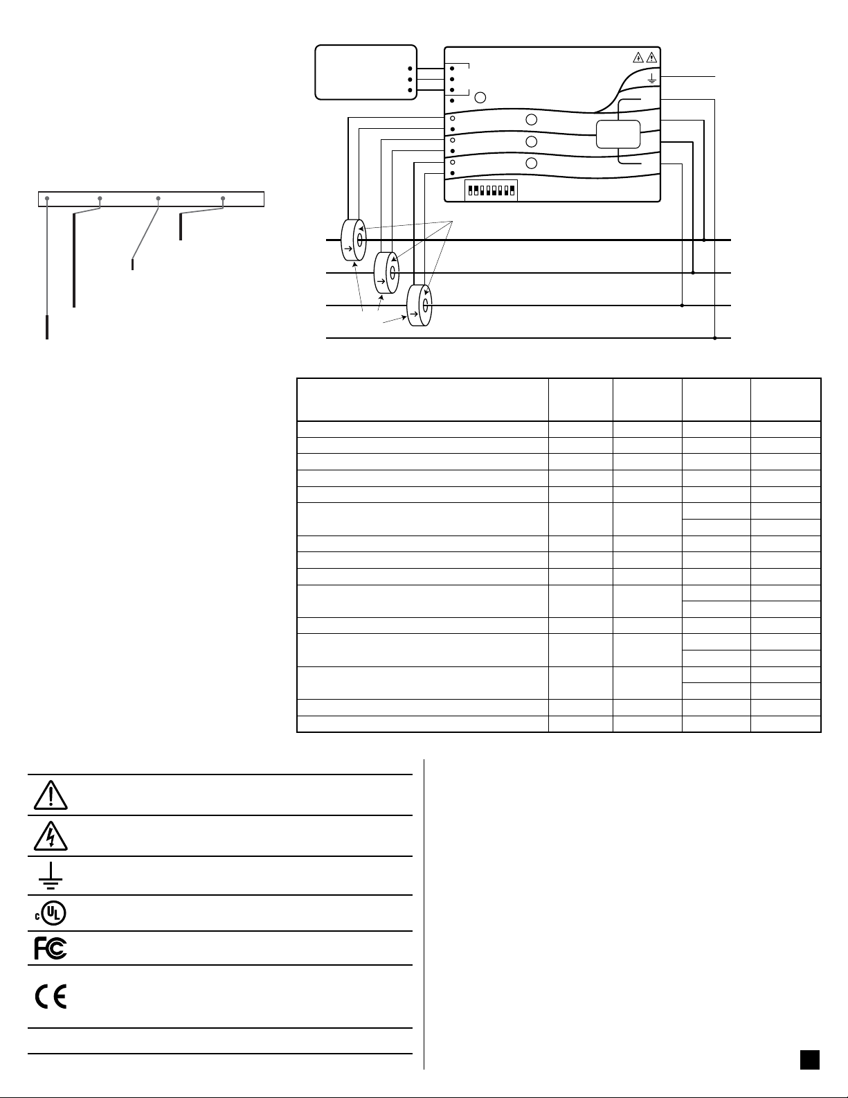
Figure 1: WattNode Wiring Diagram
Electrical
Service (or Load) Types
1 Phase 2 Wire 120V with neutral 96 – 138 n.a. 3Y-208 N and ØA
1 Phase 2 Wire 230V with neutral (non-U.S.) 184 – 264 n.a. 3Y-400 N and ØA
1 Phase 2 Wire 277V with neutral 222 – 318 n.a. 3Y-480 N and ØA
1 Phase 2 Wire 208V no neutral n.a. 166 – 276 3D-240 ØA and ØB
1 Phase 2 Wire 240V no neutral n.a. 166 – 276 3D-240 ØA and ØB
1 Phase 3 Wire 120V/240V with neutral 96 – 138 166 – 276
3 Phase 3 Wire Delta 208V no neutral n.a. 166 – 276 3D-240 ØA and ØB
3 Phase 3 Wire Delta 400V no neutral (non-U.S.) n.a. 320 – 460 3D-400 ØA and ØB
3 Phase 3 Wire Delta 480V no neutral n.a. 384 – 552 3D-480 ØA and ØB
3 Phase 4 Wire Wye 120V/208V with neutral 96 – 138 166 – 276
3 Phase 4 Wire Delta 120/208/240V with neutral 96 – 138 166 – 276 3D-240 ØA and ØB
3 Phase 4 Wire Wye 230V/400V with neutral
(non-U.S.)
3 Phase 4 Wire Wye 277V/480V with neutral 222 – 318 384 – 552
3 Phase 4 Wire Delta 240/415/480V with neutral 222 – 318 384 – 552 3D-480 ØA and ØB
3 Phase 4 Wire Wye 347V/600V with neutral 278 – 399 480 – 690 3Y-600 N and ØA
Table 1: WattNode Models
Line-to-
Neutral
(Vac)
184 – 264 320 – 460
Line-to-
Line
(Vac)
WattNode
Service
Type
3Y-208 N and ØA
3D-240 ØA and ØB
3Y-208 N and ØA
3D-240 ØA and ØB
3Y-400 N and ØA
3D-400 ØA and ØB
3Y-480 N and ØA
3D-480 ØA and ØB
Meter
Powered
by
1.9 Symbols
V~
Read, understand, and follow all instructions including warnings
and precautions before installing and using the product.
Potential Shock Hazard from Dangerous High Voltage.
Functional ground; should be connected to earth ground if possible,
but is not required for safety grounding.
UL Listin g mark. This s hows the UL an d cUL (Canadia n) listing
mark.
FCC Mark. This logo indicates compliance with part 15 of the FCC
rules.
Complie s with t he regul ation s of the Euro pean Uni on for Pr oduct
Safety and Electro-Magnetic Compatibility.
• Low Voltage Directive – EN 61010-1: 2001
• EMC Directive – EN 61327: 1997 + A1/1998 + A2/2001
This indicates an AC voltage.
2 Overview
Congrat ulati ons on yo ur pur chas e of the Wat tN ode® BACnet® watt/ watt -hou r
transducer (meter). The WattNode mete r enables you t o make power and energy measurements within electric service panels avoiding the costly installation of subpanels and associated wiring. It is designed for use in demand side
management (DSM), submetering, and energy monitoring applications. The
WattNod e meter commun icates on an EI A RS- 485 two -wire bu s using the
BACnet protocol.
2.1 Additional Literature
See the Continental Control Systems, LLC website (www.ccontrolsys.com)
for product pages, datasheets, and support pages for all WattNode meter models and cur rent tr ansfor mers. E ach Watt Node m odel has a n Operating and
Reference Guide with detail ed inform ation on th e available mea surements
and interface.
2.2 Electrical Service Types
Tab l e 1 a bove lists the Wat tNode m odels and c ommon ci rcuit ty pes. In the
“Elect ric al Ser vi ce Types” col umn, whe n two vol tage s are liste d with a s lash
between them, they indicate the line-to-neutral / line-to-line voltages. The
“Line-to -Neutral” and “Line -to-Line” columns show the operating ranges for
the WattNode meters.
1
Page 2
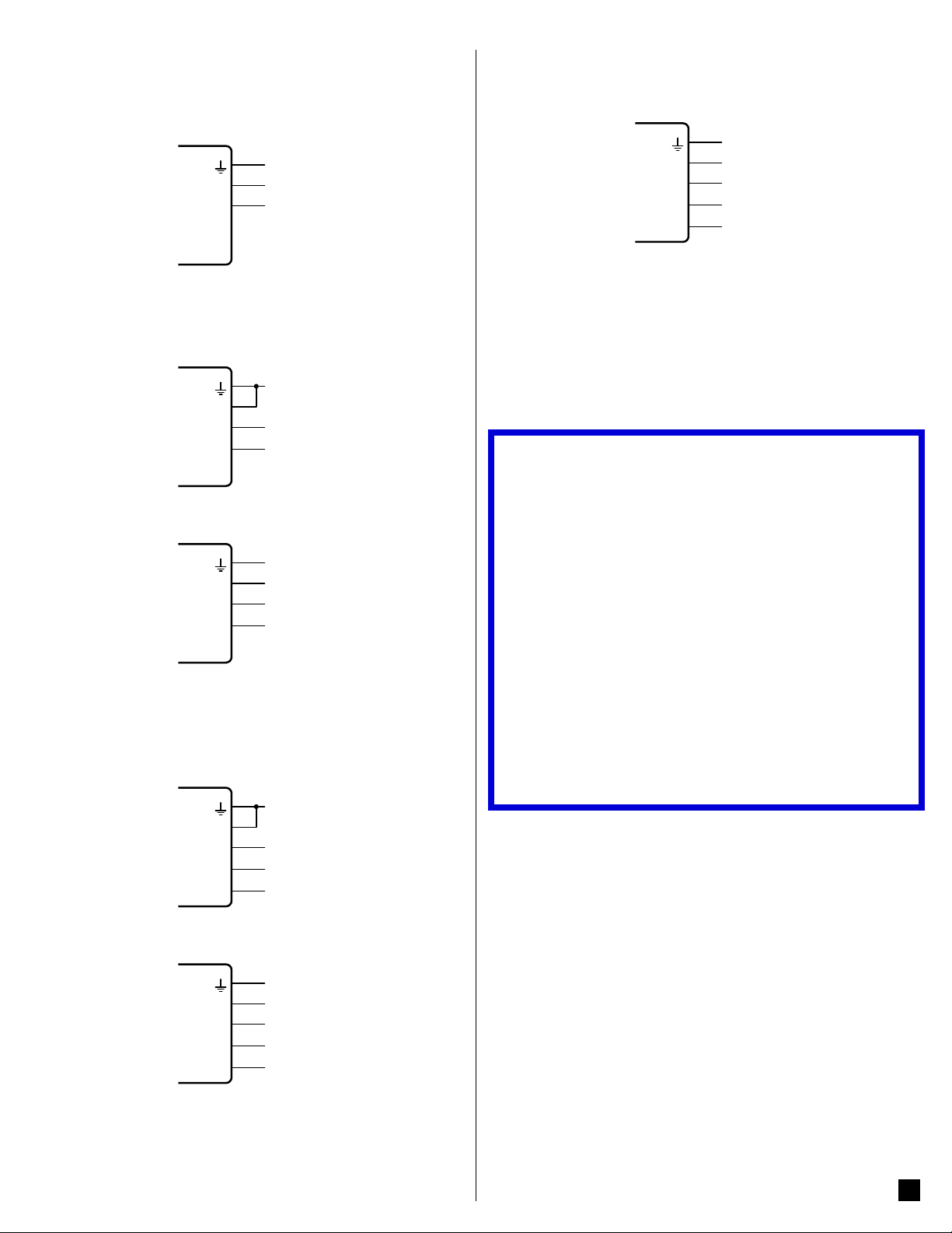
Connect the line voltages to the meter inputs as shown in the following figures
Ground
Ground
Ground
Ground
Ground
Ground
for each service type. See Figure 1 above for an overview.
2.2.1 Single-Phase Two-Wire with Neutral
This is a co mm o n re si d ent ia l an d b ra nc h c i rc ui t c o nn ec t i on . Up to t h re e su ch
circuits may be monitored with one meter by also using the ØB and ØC inputs.
W
ATT
N
N
ØA
ODE
ØB
®
ØC
2.2.2 Single-Phase Two-Wire No Neutral
This circuit occurs in residential (commonly 120/240 Vac) and some commercial
applications. The meter is powered from the ØA and ØB terminals. We recommend connecting the N terminal to ground to provide a clean voltage reference
for the measurement circuitry (no current will flow through this terminal).
Neutral
Line
W
ATT
N
N
ØA
ODE
ØB
®
ØC
2.2.3 Single-Phase Three-Wire with Neutral
This is a common residential service at 120/240 Vac.
L1
L2
W
ATT
N
N
ØA
ODE
ØB
®
ØC
2.2.4 Three-Phase Three-Wire Delta No Neutral
This is co mmon in comm ercial and in dustrial se ttings. In s ome cases, t he
service may be four-wire, wye but the load may only be three wire (no neutral).
Occasionally, a load will only be connected to two of the three lines (say L1 and
L2). For this case, connect the two active lines to the ØA and ØB terminals and
connect two CTs for the two lines.
Neutral
L1
L2
W
ATT
N
N
ØA
ODE
ØB
®
ØC
2.2.5 Three-Phase Four-Wire Wye with Neutral
This is a common commercial and industrial service.
L1
L2
L3
W
ATT
N
ODE
N
ØA
ØB
®
ØC
Neutral
L1
L2
L3
the high le g of a four-w ire th ree - phas e delt a ser v ic e to be lab ele d as the “ C”
phase instea d of the “ B ” pha se. The Wat tN od e meter w ill wo rk c or rec tly w ith
the high-leg connected to ØA, ØB, or ØC.
See the web article Four Wire Delta Circuits for more information.
W
ATT
N
N
ØA
ODE
ØB
®
ØC
2.2.7 Grounded Leg Service
In rare cases with delta services or single-phase two-wire ser vices without
neutral, one of the phases may be grounded.
The WattNode meter will correctly measure services with a grounded leg, but
the measur e d vo l t a g e a n d p o we r f o r t h e g r o u n d e d p h a s e w i l l b e ze r o a n d t h e
status LEDs (if present) will not light for the grounded phase, because the voltage is near zero. Also, this type of service may result in unusual power factors.
See the web article Grounded Leg Services for more information.
3 Installation
3.1 Installation Checklist
See the sections referenced below for installation details.
□
Mount the WattNode meter (see 3.2).
□
Turn off power before making line voltage connections.
□
Connect circuit breakers or fuses and disconnects (see 3.3.1).
□
Connec t th e lin e volt a ge w ire s to t he met er ’s gre en te rm ina l bl oc k (see
3.3.2).
□
Mount the CTs around th e li n e c o n du c to r s . M ake su re t h e CTs face th e
source (see 3.4).
□
Connec t the twis ted white and bla ck wires fr om the CTs to the black
terminal b lock o n the meter, matchi ng the wi re col ors to th e white and
black dots on the meter label (see 3.4.1).
□
Check that the CT phases match the line voltage phases (see 3.4).
□
Record t he CT r ate d c u r re nt f or e ac h m ete r, becau se i t w il l be r eq ui re d
during commissioning.
□
Connec t the out put ter minals o f the Watt Nod e meter to th e monit orin g
equipment (see 3.5).
□
Check tha t all th e wi res ar e sec ur ely in sta lle d in th e ter min al bl oc ks by
tugging on each wire.
□
Apply power to the meter.
□
Verify that the LEDs indicate correct operation (see 4.2, 4.3).
3.2 Mounting
● Protect th e me ter f r o m te mp er at ur e s be l ow –30°C (-2 2 ° F) o r a bove 5 5° C
(13 1°F), excessive moisture, dust, salt spray, or other contamination, using
a NEMA rated enclosure if necessary. The meter requires an environment
no worse than pollution degree 2 (normally only non-conductive pollution;
occasionally, a temporary conductivity caused by condensation).
● The meter must b e inst alle d in an el ec tri cal s er vi ce pa nel, an e ncl osure,
or a limited access electrical room.
● Do not use the meter as a dr illin g guid e; the dr ill c huck c an da mage t he
screw terminals and metal shavings may fall into the connectors.
The meter has two mounting holes spaced 136.6 mm (5.375 in) apart (centerto- center). Thes e mounting ho les are nor mally obsc ured by the detac hable
screw ter mina ls. Rem ove the sc rew te rmi nals t o mar k the h ole p osi tio ns and
mount the meter.
Self-tapping #8 sheet metal screws are included. Don’t over -tighten the screws,
as long-term stress on the case can cause cracking.
Neutral
L1
L2
L3
2.2.6 Three-Phase Four-Wire Delta with Neutral (Wild Leg)
The uncommon four-wire delta electrical service is a three-phase delta service
with a cent er-tap on one of t he transfo rmer wind ings to creat e a neutral fo r
single-phase loads.
The high-leg or phase with the higher voltage as measured to neutral has traditional ly b een d es ig nate d “ Ph ase B ”. A chang e to t he 2 0 0 8 N EC now al low s
3.3 Connect Voltage Terminals
3.3.1 Circuit Protection
The WattNode meter is considered “permanently connected equipment” and
requires a disconnect means (circuit breaker, switch, or disconnect) and overcurrent protection (fuse or circuit breaker).
2
Page 3
The meter onl y dr aws 10-30 m il lia mps , so t he r at ing o f any swi tc he s, di sc o n -
W
-
nects, fuses, and/or circuit breakers is determined by the wire gauge, the mains
voltage, and the current interrupting rating required.
● The switch, disconnect, or circuit breaker must be as close as practicable
to the meter and must be easy to operate.
● Use circuit breakers or fuses rated for 20 amps or less.
● Use ganged circuit breakers when monitoring more than one line voltage.
● The circ uit breakers o r fuses must pr otect the mai ns terminal s labeled
ØA, ØB, and ØC. If neut ral i s als o pr otec ted , the n th e overc ur rent p rot ec -
tion devic e must interr upt both neut ral and the un grounded c onducto rs
simultaneously.
● The circuit protection / disconnect system must meet IEC 60947- 1 and IEC
60947-3, as well as all national and local electrical codes.
3.3.2 Line Wiring
● Always disconnect power before connec ting the li ne voltag e inputs to
the meter.
● For the line voltage wires, CCS recommends 16 to 12 AWG stranded wire,
type THHN, MTW, or THWN, 600 V.
● Do not place more than one voltage wire in a screw terminal; use separate
wire nuts or terminal blocks if needed.
● Verif y t hat t he li ne vo lta ge s matc h th e lin e - to - li ne Ø- Ø and line-to- neutral
Ø-N values printed in the white box on the front label.
Connect each line voltage to the appropriate phase; also connect ground and
neutral (if applicable). The neutral connection “N“ is not required on delta models (3D-240, 3D-400, and 3D-480), but we recommend connecting it to ground
if neutral is not present.
The screw te r m in a ls h an d le w i re u p to 12 AWG. Con n ect each volt a g e li ne t o
the green te rmi nal bl ock as s hown i n Figu re 1 ab ove. Af ter th e volta ge lin es
have been con nec ted, m ake sure bo th ter min al bl ock s are fu lly se ated in t he
meter.
When power is first applied, check that the LEDs behave normally: on models
with status LEDs, if you see them flashing red-green-red-green (see Figure 7),
the line voltage is too high for this model, so disconnect the power immediately!
3.3.3 Grounding
The WattNode uses a plastic enclosure, insulation, and internal isolation barriers in stead of pr otective e art hing. Th e ground te rminal o n the gre en screw
terminal b lock i s a func tion al groun d, desi gned to im prove the m easure ment
accurac y and noi se immun ity. If nece ssar y, this ter minal may b e left d isco nnected on wye models (-3Y).
3.4 Connect Current Transformers
To meet the UL listing requirements, the WattNode meter may only be used with
these UL listed or recognized current transformer models. These all genera te
333.3 3 mi lli volt s AC at ra ted c ur re nt. S ee t he c ur re nt tr ans fo r mer d at ash eet s
for CT ratings.
ACT-0750-xxx CTL-1250-xxx CTM-0360-xxx
CTS-0750-xxx CTS-1250-xxx CTS-2000-xxxx
CTB-wwwXhhh-xxxx CTBL-wwwXhhh-xxxx CTT-0300-xxx
CTT-0500-xxx CTT-0750-xxx CTT-1000-xxx
CTT-1250-xxx
● “xxx” indicates the full scale current rating.
● “www” and “hhh” indicate the width and height in inches.
● “dddd” indicates the opening diameter of the loop for flexible Rog owski
CTs.
See the web artic le Selec ting Current Transformers for information on selecting appropriate current transformers (CTs).
● Do not use ra tio or cur rent output C Ts such as 1 amp or 5 amp output
models!
● See the CT datasheets for the maximum input current ratings.
● Be careful to match the CTs with the voltage phases. Make sure the ØA CT
is measur in g t he c u r re nt o n t he s a me p ha s e be in g m on it or e d by ØA, a nd
the same fo r p ha s e s B an d C. U s e t he s up p l i ed colore d l ab e l s o r colore d
tape to identify the CT leads.
● To minimize current measurement noise, avoid extending the CT wires,
especially in noisy environments. If it is necessary to extend the wires, use
twisted pair wire 22 to 14 AWG, rated for 300 V or 600 V (not less than the
service voltage) and shielded if possible.
● Find the source arrow or label “THIS SIDE TOWARD SOURCE” on the CT
and face/point toward the source of current.
● OPTIO NA L: if you se e spur ious r eading s on unus ed phas es, jum per th e
unused CT inp uts: for each unus ed CT, connect a shor t wire fro m the
terminal marked with a white dot to the terminal marked with a black dot.
To install the CTs, pass the conductor to be measured through the CT and connect the CT leads to the meter. Always remove power before disconnecting
any live con ducto rs. Put th e line cond uctors t hrough the CTs as shown in
Figure 1 above.
CTs are directional. If they are mounted backwards or with their white and black
wires swapped the measured power will be negative. The status LEDs indicate
negative measured power by flashing red.
Split-core CTs can be opened for installation around a conductor. A nylon cable
tie may be secured around the CT to prevent inadvertent opening.
3.4.1 CT Wiring
Connec t the w hite a nd bl ack CT w ire s to the m eter te rm inal s mar ked ØA CT,
ØB CT , and ØC CT (see Figure 1 above). Excess length may be trimmed from
the wires if desired. The current transformers connect to the six position black
screw ter minal bloc k. Conne ct each CT wi th the white w ire aligne d with the
white dot on t he l ab el , an d th e b lac k w i re a li gn e d wi t h th e bl ac k d ot . N ote t h e
order in wh ich the phas es are conn ected, as th e line voltage p hases must
match the current phases for accurate power measurement.
3.5 Connect the Output Signals
● The meter outputs are isolated from dangerous voltages, so you can con-
nect them at any time.
● If the outp ut wir ing i s near li ne volt age w ir ing, us e wire s or c abl es wit h a
300 V or 600 V rating (not less than the service voltage).
● If the outp ut w i ring is near b a r e c o n d u c to rs, it shoul d b e d o u bl e i n su la te d
or jacketed.
● You may install two wires into each screw terminal by twisting the wires to-
gether, inserting them into terminal, and securely tightening. Note: a loose
wire can disable an entire network section.
● Use twisted-pair cable (unshielded or shielded) to prevent interference.
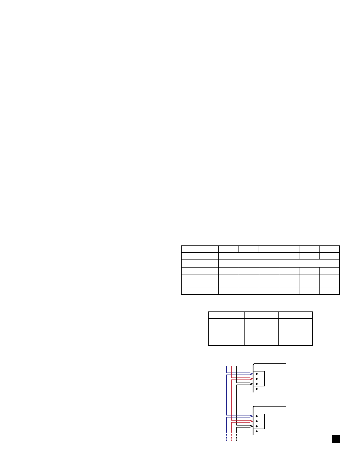
3.5.1 BACnet MS/TP
The WattN o d e BACn et m ete r can be con n ected to BACnet m on it o r i ng e q ui pment, gateways, and other BACnet devices.
Use DIP switches 1-6 to select the BACnet MAC address (0 to 63).
DIP Switch 1 2 3 4 5 6
Up (1) Value 1 2 4 8 16 32
Address Examples
1 1, Up 0, Down 0, Down 0, Down 0, Down 0, Down
1+2+4 = 7 1, Up 1, Up 1, Up 0, Down 0, Down 0, Down
4+16 = 20 0, Down 0, Down 1, Up 0, Down 1, Up 0, Down
1+2+16+32 = 51 1, Up 1, Up 0, Down 0, Down 1, Up 1, Up
Select t he b au d r ate by s etting DI P sw it c h p o si t io n s 7 an d 8 a s sh ow n b e l ow.
The change will take effect in approximately ten seconds.
Baud Rate DIP Switch 7 DIP Switch 8
9,600 (default) 0, Down 0, Down
19,200 1, Up 0, Down
38,400 0, Down 1, Up
76,800 1, Up 1, Up
3.5.2 Connect RS-485
RS
485
A-B+C
ATTNODE
-
A
+
B
C
X
WATTNODE
-
A
+
B
C
X
3
Page 4
● RS-485 wiring can be complex when multiple devices are connected, when
C
A
Green
Off
Green
Off
Green
Off
Off
C
1.0sec
C
B
A
C
B
A
C
A
Green
Off
Yellow
Off
Red
YR YR YR
running w ires for lo ng distances, and wh en using terminatio n and biasing
resistor s. If you have any quest ions, co nsult the Operating and Refer-
ence Guide.
● Be sure to connect the A-, B+, and C ( common) terminals. The X terminal
is norma lly not use d. You may use the cab le shie ld (if pr esent) for t he C
connection.
● For long distances, use shielded twisted-pair cable to prevent interference.
With shielded cable, connect the shield to earth ground at one end.
● RS- 48 5 wir ing may b e daisy- ch aine d bet ween mete rs, w ith up to 6 4 de -
vices per subnet.
4 Operation
4.1 Initial Configuration
Generally, the network integrator will remotely configure the WattNode meter
and the variables. For details on configuring the WattNode meter, see the appropriate Operating and Reference Guide for your model.
The meter does not include a display or buttons, so it is not possible to configure
or monitor t he m ete r di re ct ly, other t ha n th e ba si c LED di ag no st ic s d es c r ib ed
below.
At a minimum, t he CtAmps must be pro gra mme d wit h th e rate d amps o f the
attached current transformers for accurate measurements.
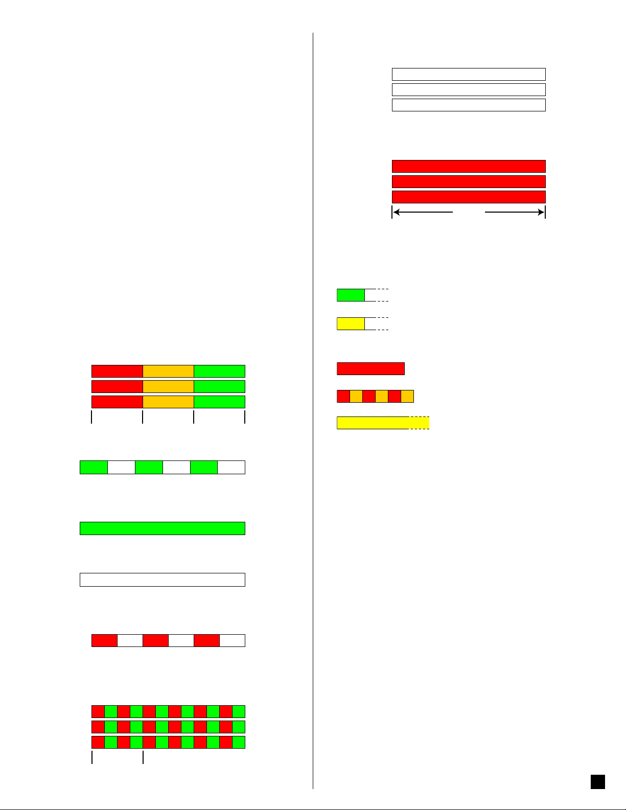
4.2 Power Status LEDs
The three status LEDs on the front of the meter can help indicate correct measurements a nd ope ratio n. The “A”, “ B”, and “C” on the dia grams i ndic ate the
three phases.
4.2.1 Normal Startup
The meter dis plays the foll owing star tup seque nce whenever p ower is fir st
applied.
GreenYellowRed
B
1.0sec1.0sec
4.2.2 Positive Power
Any phase with the LEDs flashing green is indicating normal positive power.
4.2.3 No Power
Any phase with a solid green LED indicates no power, but line voltage is present.
Green
4.2.4 No Voltage
Any phase LED that is off indicates no voltage on that phase.
GreenYellowRed
GreenYellowRed
1.0sec
4.2.7 Meter Not Operating
If none of the LEDs light, then check that the correct line volt ages are applied
to the meter. If the voltages are correct, call customer service for assistance.
Off
Off
Off
4.2.8 WattNode Error
If the meter exp er i enc e s an in ter na l er r or, it will li ght a ll LED s re d fo r th ree o r
more seconds. If you see this happen repeatedly, return the meter for service.
Red
B
Red
Red
3.0sec
For other LED patterns , see the Operating and Reference Guide or cont a ct
support for assistance.
4.3 Communication LED
Near the up per left c orner, there i s a diagnosti c Com (communication) LED
that can indicate the following:
●
this device.
●
ets addres s e d to d iffere nt dev i ces. The BACn et m o d e l w i ll o n l y sh o w t hi s
indication if it has received no packets addressed to this device for several
seconds.
●
baud rate, bad CRC, noise, bad parity, etc.
●
dress conflict (two devices with the same DIP switch address).
●
is the sole master device on the network. It will scan continuously for other
devices until another device is found.
A shor t green f las h indic ates a val id pac ket addres sed to
Short yell ow fl ashes o r rapi d fla shing i ndic ate valid p ack-
A one second red flash indicates an invalid packet: bad
Rapid red/yellow flashing indicates a possible ad-
Yellow
Solid yellow indicates that this meter believes it
4.4 Monitoring
The meter do es no t inc lu de a di spl ay or but t ons , so it i s not p os sib le to o pe rate the meter di rectly. The fol lowing is a brief overview of the possible remote
monitoring.
WattNode BACnet models communicate measurements over a BACnet MS/
TP network. The measurements include: energy, power, voltage, current, line
frequency, power factor, reactive power, and demand.
In order to mo n it o r an d confi g ur e n etworked WattNode m odels, you w il l n ee d
an appropriate monitoring solution, either standalone or PC software.
See the Operating and Reference Guide for a c omp lete lis t of net work a ccessible variables.
4.2.5 Negative Power
Red flashing indicates negative power for that phase. Reversed CTs, swapped
CT wires, or CTs not matched with line voltage phases can cause this.
Off
Red
4.2.6 Overvoltage Warning
The following indicates that the line voltage is too high for this model. Discon-
nect power immediately! Check the line volta ges and t he meter r atings (i n
the white box on the label).
GR GR GR GR GR GR
GR GR GR GR
GR GR GR GR
Red
Off
Red
Off
GR GR
GR GR
4.5 Maintenance and Repair
The WattN od e mete r re qui res n o ma inte nan c e. It is n ot us er se rvice ab le an d
there are no replaceable parts except the pluggable screw terminals. There are
no diagnostic tests that can be performed by the user, other than checking for
errors via the communications interface or the status LEDs.
In the event of any failure, the meter must be returned for service (contact CCS
for an RMA). For a n ew i ns t a l la t i o n, f o ll o w t h e di a gn o s t i c an d t r o u b le s h o o t in g
instructions in the Operating and Reference Guide before returning the meter
for service, to ensure that the problem is not connection related.
The WattN ode m eter s houl d not n or mall y nee d to be c le aned , but if c le anin g
is desired, power must be disconnected first and a dry or damp cloth or brush
should be used.
4
Page 5
5 Specifications
The following is a list of basic specifications. For extended specifications, see
the Operating and Reference Guide.
5.1 Accuracy
The following accuracy specifications do not include errors caused by the current transformer accuracy or phase angle errors. “Rated current” is the current
that generates a CT output voltage of 0.33333 Vac.
5.1.1 Normal Operation
● Line voltage: -20% to +15% of nominal
● Power factor: 1.0
● Frequency: 48 - 62 Hz
● Ambient Temperature: 23°C ± 5°C
● CT Current: 5% - 100% of rated current
Accuracy: ±0.5% of reading
For accuracy at other conditions, see the reference guide.
5.2 Measurement
Update Rate: Internally, all measurements are performed at this rate.
● 1.0 second
Start-Up Time: the meter starts measuring power/ energy and reporting mea-
surements or generating pulses this long after AC voltage is applied
● ~1.3 second (energy m easureme nt star ts ~30 0 millisec onds af ter AC
is applied)
Default CT Phase Angle Correction: 0.0 degrees.
5.3 Models and Electrical Specifications
The service “3Y-208” applies to the models WNC-3Y-208-BN,
RWNC-3Y-208-BN, and so on for the other service types.
Service
3Y-208 120 208–240 1 - 3 2 - 4
3Y-400 230 400 1 - 3 2 - 4
3Y-480 277 480 1 - 3 2 - 4
3Y-600 347 600 1 - 3 2 - 4
3D-240 120* 208–240 1 - 3 2 - 4
3D-400 230* 400 3 2 - 4
3D-480 277* 480 3 2 - 4
* Note:thedeltamodelshaveanoptionalneutralconnectionthatmaybeused
for measuring wye circuits. In the absence of neutral, voltages are measured
with respect to ground. Delta WattNode models use the phase A and phase
B connections for power.
Over-Voltage Limit: 125% of nomi nal V ac. Extended o ver-voltage operation
can damage the WattNode and void the warranty.
Over- Curre nt Limit : 120% of rated cur rent. Exce eding 120% of rated c ur-
rent will not harm the WattNode meter but the current and power will not be
measured accurately.
Maximum Surge: 4kV according to EN 61000-4-5
Power Consumption: The followin g tabl es show s maxi mum volt- amp eres,
the power supply ranges, typical power consumption, and typical power factor values with all three phases powered at nominal line voltages. The power
supply draw s most of the tota l power cons umed, while t he measureme nt
circuit r y dr aws 1-10% of the tota l (6 - 9 6 mi lli wat ts p er ph ase, d epe ndi ng on
the model). D ue to th e des ign of t he p ower sup ply, WattN ode m eter s draw
slightly more power at 50 Hz.
Nominal Vac
Line-to-Neutral
Table 2: WattNode Model Service Types
Nominal Vac
Line-to-Line
Phases Wires
Service
3Y-208 4 VA 96 – 138 N and ØA
3Y-400 4 VA 184 – 264 N and ØA
3Y-480 4 VA 222 – 318 N and ØA
3Y-600 4 VA 278 – 399 N and ØA
3D-240 4 VA 166 – 276 ØA and ØB
3D-400 3 VA 320 – 460 ØA and ØB
3D-480 3 VA 384 – 552 ØA and ØB
Table 3: Service Volt-Amperes and Power Supply Range
(1)
Note:TheRated VA is the maximum at 115% of nominal Vac at 50 Hz. This
is the same as the value that appears on the front label of the meter.
Service
Maximum Power Supply Volt age Range: -20% to +15% of nominal (see
table above). For the 3 D-24 0 ser vic e, this is - 20% of 20 8 Vac (166 Vac) to
+15% of 240 Vac (276 Vac).
Operating Frequencies: 50/60 Hz
Measurement Category: CAT III
Measurem ent catego ry III is f or measure ments per forme d in the build ing
installation. Examples are measurements on distribution boards, circuitbreakers, wiring, including cables, bus-bars, junction boxes, switches, socket-outlets in the fixed installation, and equipment for industrial use and some
other equipment, for example, stationary motors with permanent connection
to the fixed installation.
The line volt age m eas urem ent ter mi nals o n the m eter ar e rate d for t he fo llowing CAT III voltages (these ratings appear on the front label):
Current Transformer Inputs:
Nominal Input Voltage (At CT Rated Current): 0.33333 Vac RMS
Absolute Maximum Input Voltage: 5.0 Vac RMS
Input Impedance at 50/60 Hz:23kΩ
Rated
VA
3Y-208 1.5 W 1.8 W 0.79
3Y-400 1.6 W 1.8 W 0.73
3Y-480 1.6 W 2.0 W 0.69
3Y-600 1.0 W 1.3 W 0.76
3D-240 1.2 W 1.5 W 0.70
3D-400 1.1 W 1.4 W 0.67
3D-480 1.2 W 1.6 W 0.70
Table 4: Power Consumption
Service CAT III Voltage Rating
3Y-208
3D-240
3Y-400
3D-400
3Y-480
3D-480
3Y-600 600 Vac
Table 5: WattNode CAT III Ratings
Power Supply
(1)
Range (Vac)
Real Power
(60 Hz)
Power Supply
Real Power
(50 Hz)
240 Vac
400 Vac
480 Vac
Terminals
Power
Factor
5.4 EIA RS-485 Interface
RS-485 Output Isolation: 4500 Vac RMS
Driver Output:
● Voltage (Open Circuit): ±6 Vdc maximum
● Voltage (54 Ω load): ±1.5 Vdc minimum
● Current (54 Ω load): ±60 mA typical
● Rise Time (54 Ω || 50 pF load): 900 nS typical
Receiver:
● Common-Mode Range: -7 Vdc to +12 Vdc max
● Sensitivity: ±200 mV
● Bus Load: 1/8 unit load (up to 64 meters)
● Failsafe Modes: bus open, shorted, and idle
5
Page 6
5.5 Certifications
Safety:
● UL 61010-1
● CAN/CSA-C22.2 No. 61010-1-04
● IEC 61010-1
Immunity: EN 61326: 2002 (Industrial Locations)
Electrostatic Discharge: EN 61000-4-2
Radiated RF Immunity: EN 61000-4-3
Electrical Fast Transient / Burst: EN 61000-4-4
Surge Immunity: EN 61000-4-5
Conducted RF Immunity: EN 61000-4-6
Voltage Dips, Interrupts: EN 61000-4-11
Emissions:
● FCC Part 15, Class B
● EN 55022: 1994, Class B
5.6 Environmental
Operating Temperature: -30°C to +55°C (-22°F to 131°F)
Altitude: Up to 2000 m (6560 ft)
Operating Humidity: non-condensing, 5 to 90% relative humidity (RH) up to
40°C, decreasing linearly to 50% RH at 55°C.
Pollution: POLLUTION DEGR EE 2 - Norma lly only non -co nductive p ollu-
tion; occ asion ally, a temporar y co nduct ivity c aused by c onden sation m ust
be expected.
Indoor Use: Suitable for indoor use.
Outdoor Use: Suitable for outdoor use if mounted inside an electrical enclo-
sure (Hammond Mfg., Type EJ Series) rated NEMA 3R or 4 (IP 66).
5.7 Mechanical
Enclosure: High impact, ABS/PC plastic
Flame Resistance Rating: UL 94V-0, IEC FV-0
Size: 153 mm × 85 mm × 38 mm (6.02 in × 3.35 in × 1.50 in)
Connectors: Euroblock pluggable terminal blocks
Green: up to 12 AWG (2.5 mm
Black: up to 12 AWG (2.5 mm2), 300 V
2
), 600 V
5.8 FCC Information
This equip ment has been te sted and com plies with t he limits for a C lass B
digital device, pursuant to part 15 of the FCC Rules. Operation is subject to the
followin g t wo c ond iti ons: (1) This device may no t ca use ha rm ful i nterferen c e,
and (2) this device mu st acc ept any inter fer ence r ecei ved, incl uding int er ference that may cause undesired operation.
The FCC limits are designed to provide reasonable protection against harmful
interf eren ce i n a res ide ntia l inst all atio n. Th is equ ipm ent ge ner ates, u ses a nd
can radiate radio frequency energy and, if not installed and used in accordance
with the instructions, may cause harmful interference to radio communications.
However, there is no gua rant ee th at inte rferenc e w ill n ot oc c ur in a p articu lar
installation. If this equipment does cause harmful interference to radio or television reception, which can be determined by turning the equipment off and on,
the user is encouraged to try to correct the interference by one or more of the
following measures:
● Reorient or relocate the receiving antenna.
● Increase the separation between the equipment and receiver.
● Connect the equipment into an outlet on a circuit different from that to which
the receiver is connected.
● Consult the dealer or an experienced radio/TV technician for help.
5.9 Warranty
All prod u cts sold by C o ntinental Control S y s te m s , L LC (CC S) are gu a r a n te ed
against defe cts in mater ial and wor kmanship fo r a period of f ive years f rom
the original date of shipment. CCS’s responsibility is limited to repair, replacement, or ref und, any of wh ich may b e sele cted by CC S at its s ole di scret ion.
CCS reserves the right to substitute functionally equivalent new or serviceable
used parts.
WattNod e Logger m odels inc lude a lith ium batte ry to pr eser ve the date and
time during power failures. CCS will replace or provide a replacement battery at
no charge if the battery fails within five years from the original date of shipment.
This warr ant y cover s only d efec ts ar isin g unde r nor mal us e and do es not i nclude malfunctions or fail ures resulting from: misuse, neglect, improper app lication, i mpr op er in st all ati on, wat er da mag e, ac ts of n atur e, lig htni ng, p ro duc t
modifications, alterations or repairs by anyone other than CCS.
Excep t as s et f orth h er ei n , CCS m ak es n o wa r ra n ti e s, ex p re s se d or i m plied, and CCS disclaims and negates all other warranties, including
without limitation, implied warranties of merchanta bility and fitness for
a particular purpose.
5.10 Limitation of Liability
In no event shall CCS be liable for any indirect, special, incidental, punitive or co nseq uent ial d amag es of any k ind or n atur e ari sing ou t of the
sale or use of its products whether such liability is asserted on the basis
of cont rac t, t or t or o th er wi se, in clu ding w it hou t limi ta tio n, lo st pr of its ,
even if CCS has been advised of the possibility of such damages.
Customer acknowledges that CCS’s aggregate liability to Customer relating to or arisin g o ut of the sale or us e o f CCS’s products, w h e ther such
liability is asserte d on the basis of co ntract, to rt or otherwise , shall no t
exceed the purchase price paid by Customer for the products in respect
of which damages are claimed. Customer specifically acknowledges
that CCS’s price for the products is based upon the limitations of CCS’s
liability set forth herein.
©2009-2013 Continental Control Systems, LLC.
Document Number: WN-Inst-BN-1.01
Revision Date: April 17, 2013
Continental Control Systems, LLC
3131 Indian Rd., Boulder, CO 80301, U.S.A.
(303) 444-7422, http://www.ccontrolsys.com
• WattNode is a registered trademark of Continental Control Systems, LLC.
• BACnet is a registered trademark of American Society of Heating, Refrigerating
and Air-Conditioning Engineers (ASHRAE)
6
 Loading...