

Page 1
RF Design and Installation
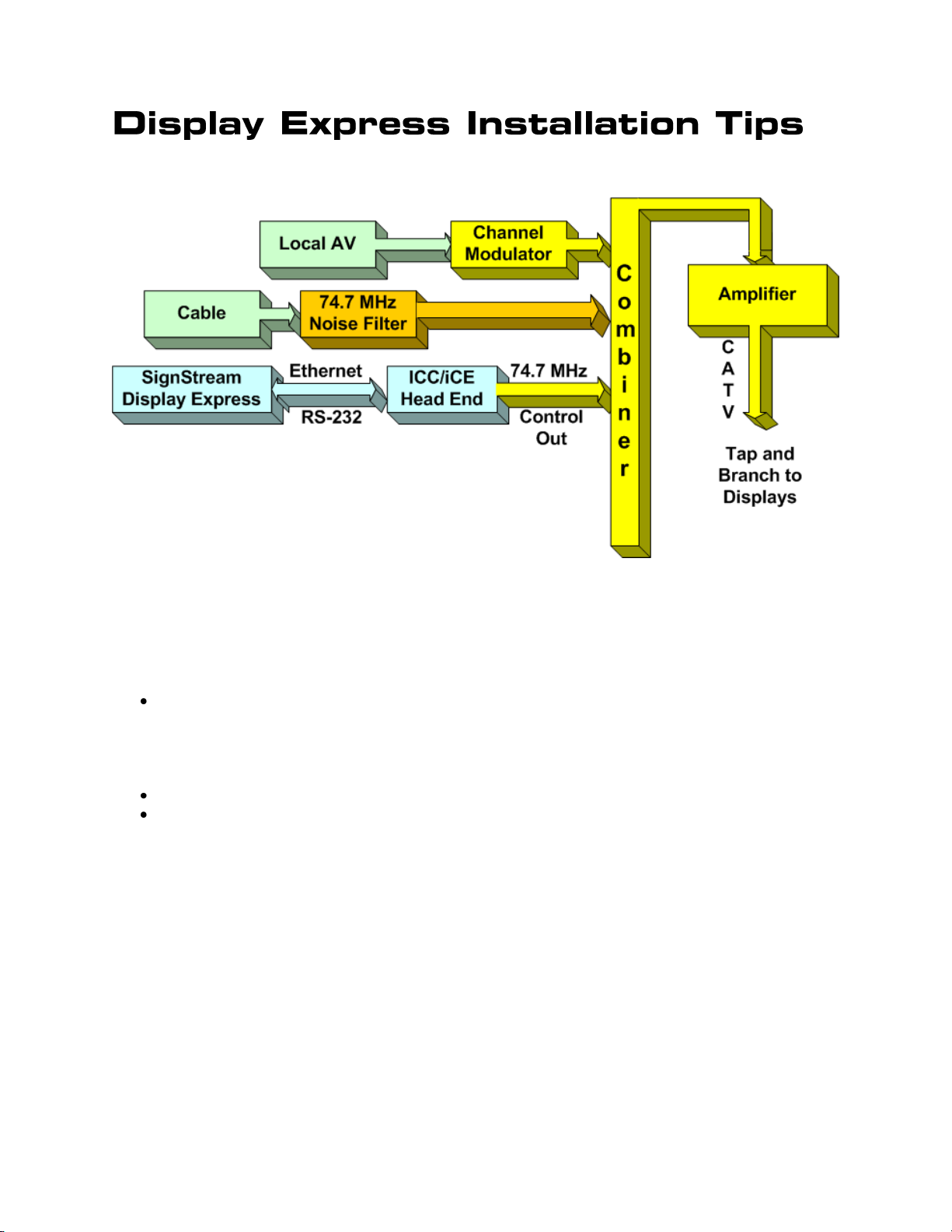
The architecture of a Contemporary Research SignStream Media Express or Display Express
display control system follows the same design as a standard RF local insertion system. A
key aspect of the system is that the underlying iC-Net technology is compatible with most
existing RF systems, and control channels used for display operation will not conflict with
current TV channels or sub-channels.
Local AV, including:
o AV sources, digital cable or satellite recievers feeding analog modulators
o Off-air HDTV channels inserted as digital QAM channels
o HD sources feeding HD cable modulators
o SignStream HDTV channels
Cable Feed, using a noise filter, if needed
SignStream or Display Express control, inserted as micro control channel
Local Sources
Each local AV source feeds an RF modulator. Analog video sources, such as DVD players, or
a PC that runs standard 4:3 digital media such as digital videos or a PowerPoint information
channel, feed the AV output of the source to an analog channel modulator. CR QMOD HD
Modulators can be used to distribute HD sources as digital QAM cable channels.
There are many ways to balance the channels, depending on the design of the system.
Obviously, the output of some channels will be reduced, while others are amplified.
Contemporary Research 1 iC-Net Tips – RF Design and Installation
Page 2
Display Control Software
Zone
Address
Zone
Address
Zone
Address
1
256
6
1536
11
2816
2
512
7
1792
12
3072
3
768
8
2048
13
3328
4
1024
9
2304
14
3584
5
1280
10
2560
15
3840
All
4095
There are several ways that CR display networks can be controlled:
Display Express software connected to an ICC-HE Head End. The Web-based control
software can be accessed anywhere on a network, usually located adjacent to Head
End.
SignStream Media Player connected to the ICC-HE Head End via RS-232 (It’s usually
in the same rack as the Head End)
Custom software, running on an AMX, Crestron, or other control system, often
connected to an ICE-HE Ethernet Head End over a network.
Installation Process
In most systems, one group of installers will integrate the displays, then another tech
comes in after that to install and test Display Express software or a custom control system.
The following installation process will allow the first team to correctly install the displays and
verify the install long before the control software is integrated.
Step One – Pre-Plan Controller Network.
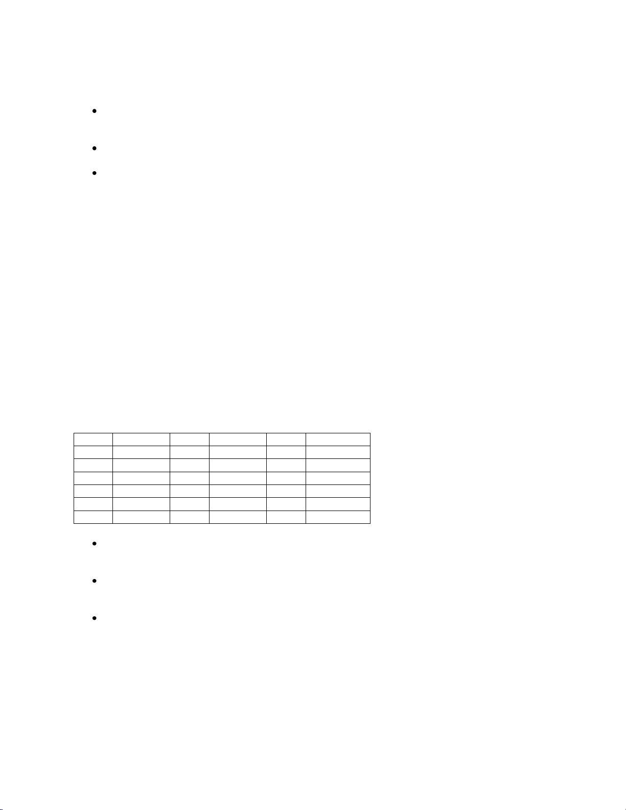
Display Controllers are identified on the RF network by unique addresses. There are 4,000
possible addresses, divided into 15 zones. All the controllers within the same zone respond
immediately to a single zone command. Some systems use a simple architecture, using the
same address for all controllers in the same zone. As control for specific controllers may be
needed in the future, it’s usually a good practice to assign each a unique address.
Zones
In most systems, try to arrange the addresses to fit into the natural Zones in the
network. This way, most commands affect all displays in each Zone with a single
command.
The new Display Express software, versions 4.3 and above, can also create free-form
Groups. This is useful for controlling a set of displays that don’t fit the normal Zone
structure.
Set up a spreadsheet that defines all the displays in the system, include the name,
location and network address. This becomes a “roadmap” for the team that installs
the displays.
From the Roadmap, go ahead and set the addresses and label the display controllers. This
simplifies the job for the team that installs the displays, and reduces system installation
errors.
Contemporary Research 2 iC-Net Tips – RF Design and Installation
Page 3

Step Two – Install ICC Head End
The ICC-HE or ICE-HE Head End will receive the RS-232 or Telnet commands from the
software and translate them to a small RF channel that runs between channels 4 and 5. It
also sends out a test command every second. The display installers can use this “pulse”
feature to confirm that the controller is “on the network”.
A common error for first-time installers is to attach the main cable feed to the RF In on the
Head End and attach the other end of the feed into RF Out. Nope. The RF In is for special 2way control signals. You use an external combiner to mix the control channel with the other
channels.
The key step in this part is to insert the RF Out of the Head End into the RF cable system.
Generally, you’ll use a combiner or splitter to combine the control channel with the main RF
feed. To do so, you want the control channel set to about the same strength as the RF
system. The Head End broadcasts at 50 dB, and includes a couple filters to knock that down
when needed.
The best technique is to use an RF meter to measure the main feed’s level, then match the
output of the Head End. The blunt approach would be to combine the Head End, then look
at how it affects other channels. If the other channels are affected, drop in a 20 dB
attenuator.
In other sites, you’ll be mixing the output of the Head End with other sources into and RF
Combiner, then amplifying the total output to the main system. Again, all the sources need
to be combined at approximately the same RF level. The best way is to use an RF meter to
measure all the sources to match. Generally, digital channels are set about 6 dB less than
analog channels. Measure the control channel as an analog channel.
Typical outputs are
RF Modulator – 45-55 dBmV
Cable Feed – 15 dBmV
Head End – 50 dBmv
QMOD Modulator – 29 dBmV
Contemporary Research 3 iC-Net Tips – RF Design and Installation
Page 4

Step Three – Pre-Set Display Controllers
S1
Off Value
On Value
1
0 1 2
0
2
3
0 4 4
0
8
5
0
16 6 0
32
7
0
64 8 0
128
S2
1 0
256
2
0
512 3 0
1024
4
0
2048
5
6
Device Mode
7
8
Device Number Setting
Ideally, you’ve already labeled the controllers and pre-set the addresses at the shop, so the
installers can just hang and bang.
Setting DIP Switches
Most display control systems employ the ICC1-232 or ICC1-IR for display control. There are
two sets of DIP switches on the bottom of each controller. They are used to set the device
number (network address) or control code type. In most cases, CR has already set the
control code type, or you can define through Display/Media Express software – so most
installers will use the switches for setting the address only.
Generally speaking, the second set of switches (S2) set the Zone address for zones 1-15.
The top switches (S2) set the unique address of the controller. If the system will always use
Zone commands for displays, you may never need to set the individual address.
Contemporary Research 4 iC-Net Tips – RF Design and Installation
Page 5

Zone Switch Settings
Zone
Value
1 2 3
4
256
512
1024
2048 1 256 X
2
512 X 3 768 X X
4
1024 X 5 1280 X X
6
1536 X X
7
1792 X X X
8
2048 X 9 2304 X X
10
2560 X X
11
2816 X X X
12
3072 X X
13
3328 X X X
14
3584 X X X
15
3840 X X X X
To define the controller’s Zone, use the following pattern of switches ON for the S2 DIP.
Controller Switch Settings
The unique address of the
controller is the combination of
the values of the Zone (S2) and
Unit (S1) switches. For example,
the first controller in Zone 1
would be set to Zone 1 (256) in
S2 and 1 (1) on S2, or 257. To
control all the displays in Zone
one, Display Express sends a
command to device 256. To
control just the first unit, create
a Preset addressed to 257.
Display Controllers
After the RF amplifier, the RF coax system branches out to the displays in the facility. Most
RF systems are designed so that each TV receives an RF level of about 10-12 dBmV for
proper channel tuning. Because the control signal is a micro-channel with far less
information than a TV channel, the controllers often work even if the display can’t effectively
tune channels.
Plan your address scheme and set controller numbers before installation. Use a label to
mark the location and address of the controller. It’s also a good idea to test a sample
display/controller combination to cross-check settings and cable wiring.
Step Four – Install Displays and Controllers\
Now that you have the system ready for installation, the process is fairly foolproof.
Network Test
One the installer connects the RF feed to the controller and plugs in the power supply, they
should set the NET LED flash once per second. As that is a result from an actual command,
that tells the installer that the controller is on the network and receiving commands. If they
don’t see the flash, someone needs to check RF setup with the Head End – or if the RF feed
in the room is connected to the central system.
Contemporary Research 5 iC-Net Tips – RF Design and Installation
Page 6

IR Control Test
S2
OFF
ON 1
Power On
2
Power Off
3
4
5
6
Test Mode On
7
8
The ICC1-IR controller has a library of codes inside. In most installs, CR has already pre-set
the control code on the unit. This can be changed with the switches, or through IC Send or
Display Express software. As a rule, the dealer should pre-set this at the shop (or with CR).
As the switches are also used to set the controller’s address, this shouldn’t be done in the
field with your level one Hang and Bang installers.
However, they can test operation very simply.
Turn S2 Switch 6 ON
Flip S2 Switch 1 On – this will send an IR Power On command to the display, then
turn the switch off
Flip S2 Switch 1 On – this will send an IR Power Off command to the display, then
turn the switch off
Turn S2 Switch 6 OFF
RS-232 Control
This step isn’t required, as we always install just one code series into the ICC1-232
controller at CR. We find that this dramatically reduces installer error. Most integrators test
one of the controllers at the shop to cross-check operation before installation.
Contemporary Research 6 iC-Net Tips – RF Design and Installation
Page 7

Step Five – IC-Send Testing
Com Setting
IP Setting
Very often, an integrator will send over a higher-level tech to test operation after the
displays are installed. At this point, there may not be a Display Express PC or software
installed as yet, or the control system code isn’t finalized. However, you can take a laptop
with free IC Send software to test the system.
IC Send is a Windows application for testing iC-Net communication and control. Setup just
takes a few steps:
Connect a Female to Female null model cable (TX and RX swapped at one end) between a PC
and a CR iC-Net Head End.
Check to make sure the DIP switches on the from of the Head End is set to 19.2 Kb.
Switch 6 set to Off, Switches 7 and 8 On.
Launch iC Send – no installation is needed.
Click Setup to choose RS-232 port or IP port.
For IP Port, enter the IP address of the Head End.
Click FIND to connect to the IC Head End, then IC Send will display “Seeking Device”.
If IC-Send connects to the Head End, the firmware version of the HE will appear at the top left
below the menus.
If you change the cable or DIP switch settings on the HE, click FIND to re-connect.
Entering Commands
Command: Enter the command code in the first field.
Parameter: Enter the parameter, if needed, in the second
Device: Enter the device or Zone number for the controller(s)
Click SEND to send the command.
Devices and Zones
To send a command to an individual controller, enter its unique address. To send a command to
an entire Zone (up to 255 controllers) or all controllers use a Zone address (see page 5).
Connect the cable to the Program Port, not the iC-Net port.
Contemporary Research 7 iC-Net Tips – RF Design and Installation
Page 8

Typical Commands
Command
Description
All Controllers
Power Off
P0
P (Zero)
Power On
P1
P (One)
Tune Analog
TC
2-127
HD Tuning
TH
<Major>,<Minor>
Example: TH then 15,1 tunes channel 15-1
Volume
VL
Sets TV volume level
0 = Mute
1 – 63 = Minimum level (1) to maximum volume (63)
Tuning
ICC1-232, ICC1-IR
Tuning Style
H1
1 = 5-digit CableCard style tuning (1-9999)
2 = Virtual HD Major-Minor tuning (tunes to virtual channel ID in display)
3 = Physical HD Major-Minor tuning (physical channel, minor digital)
RS-232
ICC1-232, ICC2-ATSC, ICC2-VDC
RS-232 Control
T0
Selects control make and model for RS-232 control. Check Manual or
www.crwww.com product Install page for codes
Tuning Format
ATSC,VDC,IRC
S0
0=CATV
1=Off-Air
2=IRC
3=HRC
4=Auto
Direct
UX
Sends an RS-232 command directly to a display or projector through the
controller’s RS-232 port.
Example:
UX 'mc 00 39',13 [Device #] sends a toggling Captions On/Off command to an
LG display.
ASCII character strings can be denoted by enclosing in single quotes (or double
quotes if you actually needed the single quote character in the string). Hex bytes
are denoted with a $ symbol. Decimal characters are without quotes.
Scan
ICC2-ATSC
Scan Mode
D0
Sets scan mode for digital and analog channels from the T^ or front panel scan
command.
0= Scans for analog and digital channels scan (default)
1= Scans for digital only, deletes analog channels
2= Scans for digital only, keeps analog channels
3= Scans for analog only, deletes digital channels
4= Scans for analog only, keeps digital channels
Channel Scan
T^
Initiates channel scan
IR ICC1-IR, ICC2-IRC
IR Code
T1=
Sets IR control code.
Check Manual or www.crwww.com Install page for codes
Contemporary Research 8 iC-Net Tips – RF Design and Installation
Page 9

Contemporary Research 9 iC-Net Tips – RF Design and Installation
 Loading...