


A-2000™
Unloading, Handling
and Installation Guide
ENGINEERED SOLUTIONS
Preface
This instruction book is for your crews. Distribute it to help them install Contech® A-2000™ correctly. They are flexible pipes that must be installed following the trench construction, bedding, haunching, initial backfill, and other requirements of ASTM D 2321,“Standard Recommended Practice for Underground Installation of Flexible Thermoplastic Sewer Pipe.”
Don’t assume experienced workers know all the answers. Review these instructions with your supervisors and crews. It can mean a better job for you and your customer.
We suggest that you adopt a policy of performance testing the first few manhole runs. It will give you an early check that installation procedures are correct.
If you have any questions about these instructions, call your Contech Distributor or your Contech Sales Engineer, or carefully review the installation guide in the Contech A-2000 catalogs and ASTM D 2321.
2

Contents |
|
Cold Weather Installation .......................... |
5 |
Unloading and Handling .......................... |
6 |
Trenching ................................................. |
8 |
Installation Tips ........................................ |
9 |
Assembly of Pipe .................................... |
10 |
A. Gasket/Pipe Connection ............... |
10 |
B. Manhole Connection .................... |
12 |
C. Field Cutting Pipe ......................... |
14 |
D. Caps ........................................... |
14 |
E. Mechanical plugs ......................... |
14 |
F. Tapping/Saddle Connections ......... |
15 |
Repairs .................................................. |
18 |
Installation of Pipe .................................. |
20 |
A. Pipe Zone/Embedment Material..... |
20 |
B. Deflection Control ........................ |
26 |
Deep Laterals ......................................... |
27 |
Special Notes ......................................... |
28 |
Standard Details...................................... |
30 |
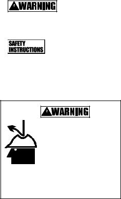
This safety alert symbol indicates important safety messages. When you see this symbol,
be alert to the possibility of personal injury and be sure you understand the message that follows.
3
Terms You Should Know
Alerts you to hazards or unsafe
practices that CAN result in severe personal injury or property damage.
Messages about procedures or actions
that must be followed for safe handling and installation of A-2000 Pipe.
Falling or rolling pipe can cause severe personal injury
or death.
Read and follow all safety instructions before unloading pipe.
4
Cold Weather Installation
1.Handle the pipe with more care in cold weather. PVC outer walls can become hardened as temperatures drop. When placing embedment materials in deep trenches and temperatures 0° - 32° F, it is required to use smaller aggregate (3/4- inch max.) and limit the height of dumping stone, not to exceed
20 feet.
2.Rubber gaskets become harder as the temperature decreases, gaskets tend to compress less, and when combined with PVC bells that become more installation sensitive, jointing becomes less forgiving. Proper bell-spigot alignment, adequate bell and spigot lubrication, and recommended joining procedures (-i.e. bar and block) all become more essential as temperature decreases.
In addition, it is recommended to store the gaskets in a warm place prior to use.
5

Unloading and Handling
The following equipment is recommended for unloading pipe pallets:
Forklift with full-length forks to engage entire pallet width, front-end loader or backhoe with fork adapters full length to engage entire pallet width.
Nylon lifting slings of sufficient strength and length to safely handle entire pallet. Do not stand or ride on the pipe load during unloading.
NOTE: Pipes sizes 18” and less are palletized with steel straps around a wood frame. Full trailer width pallets (21” to 36”) are not framed. Only forks of sufficient length to engage entire pallet width are recommended for unloading.
Table 1. A-2000 PVC Handling Weights
Diameter (in) |
Weight (lbs/ft) |
|
|
4 |
1.00 |
6 |
1.25 |
8 |
2.00 |
10 |
3.00 |
|
|
12 |
4.25 |
|
|
15 |
7.00 |
18 |
10.00 |
21 |
13.00 |
|
|
24 |
17.00 |
|
|
30 |
25.00 |
36 |
34.00 |
6

Failure to follow these instructions can result in serious injury or death and/or damage to pipe.
1.Only trained and authorized equipment operators are to be permitted to unload the trailer.
2.Wear approved safety hat and shoes, gloves, and eye protection.
3.Park the truck and trailer on level ground before you start unloading.
4.Keep all unauthorized persons clear of the area when the driver releases the binders from the trailer and during unloading.
5.Do not release steel strapping around the wood
 frame until the pallets have been placed on level
  ground and will not be moved again as a unit.
6.Know the capabilities and rated load capacities of your lifting equipment. Never exceed them.
7.Do not stand or ride on the load of pipe while it

 is being unloaded. Do not stand beneath or near


 the pipe when it’s being unloaded.
8.If unloading at multiple points, secure pallets between drop off points. For each unit of four pallets, always unload the top pallets first. (See diagram)
9.Never attach chains or wire
rope to the pipe. They could damage the pipe.
10.Do not push pallets off the trailer or permit pipe to drop to the ground.
11.Do not drag A-2000 Pipe across the ground.
12.Do not stack A-2000 Pipe over two pallets high. Stacks of three or more pallets can damage bottom pipes and can become unstable.
13.Handle A-2000 Pipe with extra care in freezing or cold weather.
7

Trenching
Trenching practice and bedding materials shall be in accordance with ASTM D2321 and OSHA rules.
1.The excavation needs to be wide enough
and be supported adequately to allow a person to work safely.
2.Where trench walls are unstable, the contractor may elect to use sheeting, stay bracing, or
a trench box for stabilization during pipe laying. If the conditions are severe, sheeting may be left in place.
3.Excessive groundwater may necessitate dewatering.
4.An unstable trench bottom must be stabilized at the engineer’s direction. In such cases, install special foundation and bedding materials in 6-inch layers and compact.
5.Excavation from 6 inches to 12 inches below the pipe should be filled with acceptable bedding material and compacted to a minimum 90% Standard Proctor Density. Fill areas of over excavation beyond 12 inches with processed stone or gravel following standard bedding practices
6.Before installing the pipe, bring bedding material to grade along the entire length of the pipe.
7.When excavating in Class IV materials (silt, silty clays, and clays), provide a uniform, undisturbed foundation.
8
Installation Tips
1.At manholes, flexible manhole connections like rubber boots, A-Loks, etc. can be used.
With rubber boot manhole connectors, install either a standard A-2000 double
gasket (8”-10”) or an A-2000 manhole gasket (12”-36”) on the pipe spigot under the stainless steel strap (see manhole connection detail on page 12). Where manholes are manufactured with A-Lok connections, use a Contech PVC manhole sleeve.
2.Do not probe for the pipe with rods, shovels, or other sharp objects when excavating down to install laterals, etc. Instead, mark the elevation of
the pipe with stakes or other markers to help locate it.
3.When haunching the pipe or digging down to install laterals, take care not to damage the pipe with shovels, or other construction equipment.
4.String only enough pipe to use during the day’s laying operations.
5.A full line of adapters to other pipes is available. See Contech A-2000 Fittings Catalogs.
6.After proper assembly, the first load of backfill should be placed over the middle of the pipe. While the first load is being placed, the free bell
end should be held safely on line by the pipe layer. This technique will minimize pipe movement during backfilling. Subsequent loads of backfill may be placed in a normal fashion.
9
Assembly of Pipe
A. Gasket/Pipe Connection
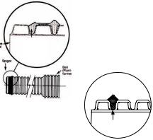
1.The double sealing surface A-2000 gaskets are fitted to the first two full corrugations on the spigot end of the pipe as shown in the drawing.
The single sealing surface A-2000 Drainage gaskets are fitted in the first corrugation valley as shown in the drawing.
Gaskets are shipped loose and require field installation on the pipe spigot. The leading (lower) edge of the gasket is marked with the Contech logo and wording to distinguish it from the seating (higher) edge.
The low height seal is fitted into the first corrugation. The double sealing gasket is fitted into the first two full corrugation valleys.
|
|
|
|
Gasket location |
|
Pipe |
|
|
|||
end |
|
|
on 4” to 36” |
|
|
|
|
|
|
diameter |
|
|
Spigot |
|
A-2000 |
|
|
|
|
|
|
|
Bell |
|
|
|
|
|
|
|
|
|
|
|
(plant- |
|
|
|
|
|
formed) |
Gasket location on A-2000 pipe
10
 Loading...