

Page 1

A-2000™
ENGINEERED SOLUTIONS
Unloading, Handling
and Installation Guide
Page 2

Preface
This instruction book is for your crews. Distribute it
to help them install Contech® A-2000™ correctly.
They are flexible pipes that must be installed
following the trench construction, bedding,
haunching, initial backfill, and other requirements
of ASTM D 2321,“Standard Recommended
Practice for Underground Installation of Flexible
Thermoplastic Sewer Pipe.”
Don’t assume experienced workers know all
the answers. Review these instructions with your
supervisors and crews. It can mean a better job
for you and your customer.
We suggest that you adopt a policy of
performance testing the first few manhole runs.
It will give you an early check that installation
procedures are correct.
If you have any questions about these instructions,
call your Contech Distributor or your Contech
Sales Engineer, or carefully review the installation
guide in the Contech A-2000 catalogs and ASTM
D 2321.
2
Page 3

Contents
Cold Weather Installation ......................... 5
Unloading and Handling .......................... 6
Trenching ................................................ 8
Installation Tips ........................................ 9
Assembly of Pipe .................................... 10
A. Gasket/Pipe Connection .............. 10
B. Manhole Connection .................... 12
C. Field Cutting Pipe ........................ 14
D. Caps ...........................................14
E. Mechanical plugs ......................... 14
F. Tapping/Saddle Connections ......... 15
Repairs .................................................. 18
Installation of Pipe ................................. 20
A. Pipe Zone/Embedment Material .... 20
B. Deflection Control ........................ 26
Deep Laterals ........................................ 27
Special Notes ........................................ 28
Standard Details ..................................... 30
This safety alert symbol indicates
important safety messages.
When you see this symbol,
be alert to the possibility of
personal injury and be sure you
understand the message that follows.
3
Page 4
Terms You Should Know
Alerts you to
hazards or unsafe
practices that CAN result in severe
personal injury or property damage.
Messages about
procedures or actions
that must be followed for safe
handling and installation of A-2000
Pipe.
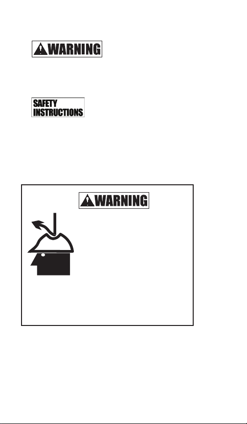
Falling or rolling pipe
can cause severe
personal injury
or death.
Read and follow all safety instructions
before unloading pipe.
4
Page 5

Cold Weather Installation
1. Handle the pipe with more care in cold
weather. PVC outer walls can become
hardened as temperatures drop. When placing
embedment materials in deep trenches and
temperatures 0° - 32° F, it is required to use
smaller aggregate (3/4- inch max.) and limit
the height of dumping stone, not to exceed
20 feet.
2. Rubber gaskets become harder as the
temperature decreases, gaskets tend to
compress less, and when combined with PVC
bells that become more installation sensitive,
jointing becomes less forgiving. Proper
bell-spigot alignment, adequate bell and
spigot lubrication, and recommended joining
procedures (-i.e. bar and block) all become
more essential as temperature decreases.
In addition, it is recommended to store the
gaskets in a warm place prior to use.
5
Page 6

Unloading and Handling
The following equipment is recommended for
unloading pipe pallets:
Forklift with full-length forks to engage entire
pallet width, front-end loader or backhoe
with fork adapters full length to engage entire
pallet width.
Nylon lifting slings of sufficient strength and
length to safely handle entire pallet. Do
not stand or ride on the pipe load during
unloading.
NOTE: Pipes sizes 18” and less are palletized with
steel straps around a wood frame. Full trailer width
pallets (21” to 36”) are not framed. Only forks of
sufficient length to engage entire pallet width are
recommended for unloading.
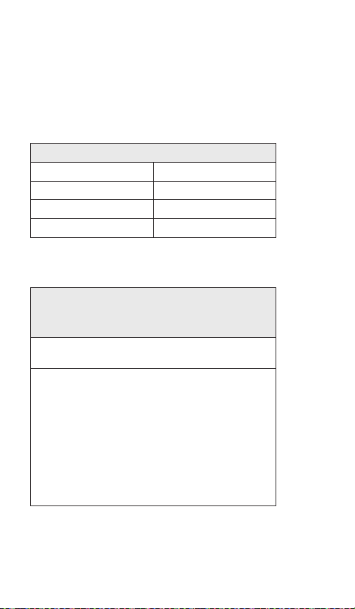
Table 1. A-2000 PVC Handling Weights
Diameter (in) Weight (lbs/ft)
4 1.00
6 1.25
8 2.00
10 3.00
12 4.25
15 7.00
18 10.00
21 13.00
24 17.00
30 25.00
36 34.00
6
Page 7
Failure to follow these instructions can result in
serious injury or death and/or damage to pipe.
1. Only trained and authorized equipment
operators are to be permitted to unload the
trailer.
2. Wear approved safety hat and shoes, gloves, and
eye protection.
3. Park the truck and trailer on level ground before
you start unloading.
4. Keep all unauthorized persons clear of the area
when the driver releases the binders from the
trailer and during unloading.
5. Do not release steel strapping around the wood
frame until the pallets have been placed on level
ground and will not be moved again as a unit.
6. Know the capabilities and rated load capacities
of your lifting equipment. Never exceed them.
7. Do not stand or ride on the load of pipe while it
is being unloaded. Do not stand beneath or near
the pipe when it’s being unloaded.
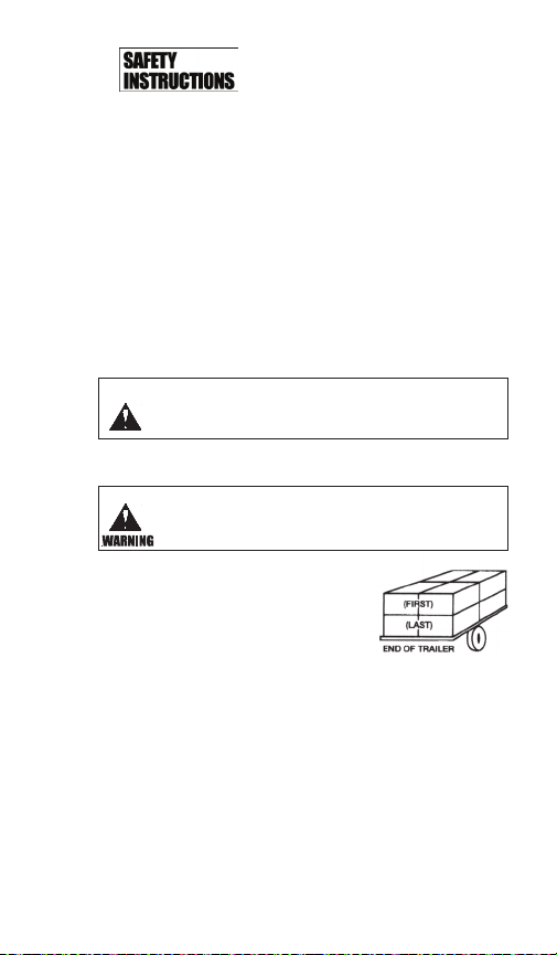
8. If unloading at multiple points,
secure pallets between drop
off points. For each unit of
four pallets, always unload the
top pallets first. (See diagram)
9. Never attach chains or wire
rope to the pipe. They could damage the pipe.
10. Do not push pallets off the trailer or permit pipe
to drop to the ground.
11. Do not drag A-2000 Pipe across the ground.
12. Do not stack A-2000 Pipe over two pallets high.
Stacks of three or more pallets can damage
bottom pipes and can become unstable.
13. Handle A-2000 Pipe with extra care in freezing
or cold weather.
7
Page 8

Trenching
Trenching practice and bedding materials shall be
in accordance with ASTM D2321 and OSHA rules.
1. The excavation needs to be wide enough
and be supported adequately to allow a
person to work safely.
2. Where trench walls are unstable, the contractor
may elect to use sheeting, stay bracing, or
a trench box for stabilization during pipe laying. If
the conditions are severe, sheeting may be left in
place.
3. Excessive groundwater may necessitate dewatering.
4. An unstable trench bottom must be stabilized at the
engineer’s direction. In such cases, install special
foundation and bedding materials in 6-inch layers
and compact.
5. Excavation from 6 inches to 12 inches below the
pipe should be filled with acceptable bedding
material and compacted to a minimum 90%
Standard Proctor Density. Fill areas of over
excavation beyond 12 inches with processed stone
or gravel following standard bedding practices
6. Before installing the pipe, bring bedding material
to grade along the entire length of the pipe.
7. When excavating in Class IV materials (silt, silty
clays, and clays), provide a uniform, undisturbed
foundation.
8
Page 9

Installation Tips
1. At manholes, flexible manhole connections like
rubber boots, A-Loks, etc. can be used.
With rubber boot manhole connectors, install
either a standard A-2000 double
gasket (8”-10”) or an A-2000 manhole gasket
(12”-36”) on the pipe spigot under the stainless
steel strap (see manhole connection detail on page
12). Where manholes are manufactured with A-Lok
connections, use a Contech PVC manhole sleeve.
2. Do not probe for the pipe with rods, shovels, or
other sharp objects when excavating down to
install laterals, etc. Instead, mark the elevation of
the pipe with stakes or other markers to help locate it.
3. When haunching the pipe or digging down to
install laterals, take care not to damage the pipe
with shovels, or other construction equipment.
4. String only enough pipe to use during the day’s
laying operations.
5. A full line of adapters to other pipes is available. See
Contech A-2000 Fittings Catalogs.
6. After proper assembly, the first load of backfill
should be placed over the middle of the pipe.
While the first load is being placed, the free bell
end should be held safely on line by the pipe layer.
This technique will minimize pipe movement during
backfilling. Subsequent loads of backfill may be
placed in a normal fashion.
9
Page 10

Assembly of Pipe
A. Gasket/Pipe Connection
1.The double sealing surface A-2000 gaskets
are fitted to the first two full corrugations on the
spigot end of the pipe as shown in the drawing.
The single sealing surface A-2000 Drainage
gaskets are fitted in the first corrugation valley
as shown in the drawing.
Gaskets are shipped loose and require field
installation on the pipe spigot. The leading
(lower) edge of the gasket is marked with the
Contech logo and wording to distinguish it from
the seating (higher) edge.
The low height seal is fitted into the first
corrugation. The double sealing gasket is fitted
into the first two full corrugation valleys.
10
Pipe
end
Spigot
Gasket location
on 4” to 36”
diameter
A-2000
Bell
(plantformed)
Gasket location
on A-2000 pipe
Page 11

2. Thoroughly clean the bell and spigot ends,
making sure they are free of mud and grit. If the
gasket has been removed, make sure the gasket
seat (the first two full corrugation valleys) is
clean. Reinstall the gasket by stretching it over
the spigot end and nesting it into the seat.
3. Use a Johnny mop or brush to apply a liberal
amount of gasket lube to the gasket and to
swab the inside of the bell. Take care to lube
the chamfered (leading) edge of the bell. Keep
lube and lubed surfaces free of debris.
4. Align the joint and push the spigot to the
corrugation with the homemark. The total
corrugation, with the homemark, should be
visible when the pipe is properly “homed.” When
using a bar and wood block, make sure the
block protects the pipe end from the bar. It is
recommended to use a nylon sling to facilitate
handling and joining 21” diameter and larger
A-2000. When joining, NEVER use the backhoe
bucket to push against the pipe bell. When
pushing the joint home, make sure the bedding
material is not pulled into the bell by the spigot.
Material such as small stones or sand pulled into
the bell as the pipe is stabbed can impair gasket
sealing and cause leaks.
11
Page 12

B. Manhole Connection
At manholes, flexible manhole connections like
rubber boots, A-Loks, etc. can be used.
1. Boot: With rubber boot manhole connectors,
install either a standard A-2000 double gasket
(8”-10”) or an A-2000 manhole gasket (12’-36”)
on the pipe spigot under the stainless steal strap
(See manhole connection detail A.)
2. A-Lok: Where manholes are manufactured
with A-Lok connections, use a Contech PVC
manhole sleeve (See manhole
connection detail B.)
If the manhole sleeves are
not attached and the need
arises in the field, follow the
procedure below.
• Place a standard gasket
on the pipe about 6” from the end. Lube
the gasket and the manhole sleeve and
slide the manhole sleeve onto the pipe end.
Restrict the coupling from sliding and push
the unit (pipe and coupling) into the A-Lok
connection (lube the A-Lok).
Manhole Detail B
12
Manhole Detail A
Page 13

3. Waterstop type manhole connections can be
accomplished using A-2000 pipe gaskets. For
cast-in-place concrete bottoms, precast bottoms
with “mouse hole” or similar pipe-to-manhole
entry that does not incorporate a flexible
connection, use two standard A-2000 double
gaskets for 8”-and 10”-diameter pipe, positioned
on the pipe in the center of the manhole wall
with the leading (the lower) edge of the gaskets
in adjacent corrugations, then concrete grout or
seal the pipe/manhole connections as required.
For pipe with diameters of 12”-36” inches, use
one standard A-2000 double gasket, positioned
on the pipe in the center of the manhole wall,
with the leading (lower) edge of the gasket closest
to the inside of the manhole.
Waterstop Manhole Connection
13
Page 14

C. Field Cutting Pipe
A-2000 can be field cut to length. Cut through
a corrugation valley using a hand or power
saw. Fit the gasket following the procedure
listed in “Gasket/Pipe Connection.”
D. Installing Caps
Caps are installed the same way you make a
gasketed joint. Caps need to be staked to make
sure they are secure. Mark the lateral location and
depth with a lath or other marker so that probing,
etc. to locate the pipe is not required.
E. Installing Mechanical Plugs
Mechanical plugs may be used, but caps
are recommended. (Mechanical plugs
should not be used for air testing.)
Install mechanical plugs by following
these steps:
1. DO NOT USE LUBRICANT.
2. Insert into the pipe barrel, beyond the
bell, until the back of the washer seats
against the bell hub transition.
3. Hold and tighten the wing nut until
firmly seated.
4. Stake the plug to keep safely secured during
testing. Proper staking requires a spacer from
the plug in the bell to a stake driven outside
the bell.
5. Mark the lateral location and depth with
a lath or other marker so the probing
etc. to locate the pipe is not required.
14
Page 15

F. Tapping/Saddle Connections
Saddle fittings are used for tapping
in-service systems. Use inline fittings
for new construction. Ribbed A-2000
saddles must line up with pipe corrugations.
Stick-on templates are marked for proper
orientation.
Follow these steps:
1. Place template on the pipe to mark the
outline of the hole. Take care to line up the
template with the corrugation valley properly.
Instructions are located on the template.
2. Use keyhole or saber saw to cut the
hole. Do not start the hole with a
hammer or hatchet. Use a drill, awl, or
other sharp cutting tool.
3. Thoroughly clean the pipe and saddle
mating areas (e.g. MEK cleaner or other).
Place the saddle in position on the pipe
and draw a line around the outer
edge of the saddle skirt to mark the
area of pipe to be covered by the
saddle. Use the recommended adhesive
(Sikaflex® or similar) provided by others.
Adhesive is in the caulking tube that uses a
standard caulking gun. Proceed as
described on the following page.
15
Page 16

3.A. For saddles with ribbed skirt.
3.A.1. Place a 1/4 -inch bead around the
cut opening in the pipe. Continue to make
concentric rings with 1/4 -inch beads of
adhesive about 1/4 -inch apart. The final
ring should be just inside the area to be
covered by the saddle skirt. Make certain
when crossing corrugation valleys that the
adhesive bead flows into the valley.
3.A.2. Apply adhesive to the underside of
the saddle skirt in a similar fashion.
3.B. For saddle with smooth (underside) skirt.
3.B.1. Completely fill the corrugation
valleys of the pipe with adhesive. The
bead should completely fill the valleys
and bulge above the corrugation crests
throughout the area to be covered by the
saddle.
3.B.2. Place a 1/4 -inch bead around the
cut opening in the pipe. Continue to make
concentric rings with 1/4 -inch apart. The
final ring should be just inside the area to
be covered by the saddle skirt.
16
Page 17

3.B.3 Apply adhesive to the underside of the
saddle skirt in a similar fashion.
With either type of skirt, a bead of adhesive can
be applied to the cut edge of the pipe wall to seal
the profile if desired.
NOTE: 8-inch to 36-inch saddle gaskets are also
available to be used with smooth skirt saddles.
Step 3.B.1. is not required for saddles with
gaskets. In steps 3.B.2. and 3.B.3., adhesive may
be applied to either the saddle or gasket surface.
4. Place saddle in position on the pipe
and cinch in place with the two steel
straps provided. Tighten straps
uniformly by alternating back and forth
between them, tapping the saddle
lightly with a rubber mallet to aide in
firmly seating the saddle in position (do
not over-tighten the straps).
5. For attaching 21-inch to 36-inch (only)
A-2000 saddle fittings with
the smooth saddle skirt, follow the
procedure described in Steps 1, 2, 3,
and 3B above. In addition, place
saddle in position on the pipe and
fasten in place with the stainless steel
screws provided. Holes are predrilled in
saddles for location of screws.
17
Page 18

Repairs
Cut out damaged areas and cut a length of
replacement pipe to fit. Use two flexible rubber
couplings and follow these steps:
1. Expose the existing cut pipe ends to give working
room under them.
2. Install a flexible rubber adapter on each end of
the replacement section. Using gasket lube or
vegetable oil as a lubricant, slide (or roll) the
adapters back and position the replacement
section.
3. Slide (or roll) the adapters over the joint at each
end of the replacement section so they
are centered over the joint. Use gasket lube or
vegetable oil as a lubricant.
4. Tighten the two stainless steel bands, making
certain they are properly positioned.
5. When optional shear stops are required, the
split plastic ring is snapped around the repair
coupling between the stainless steel bands
(Steps 3 and 4). This ring is held in place by two
additional stainless steel straps. The shear stop is
installed prior to re-establishing bedding support.
6. Tamp bedding material under the points where
it was disturbed. Replace haunching and initial
backfill throughout the disturbed area.
Alternate Repair Procedure
18
Page 19

Cut out damaged areas.
Place couplings over each spigot end of embedded pipe.
Place gaskets on each spigot end of the
embedment pipe backwards (with the higher or
seating edge of the gasket adjacent to the pipe
cut.) Place gaskets on each end of the replacement
piece in the recommended fashions. Draw
homemarks a half coupling length from end
of each spigot end on the replacement length.
Liberally lube all gaskets and inside of couplings.
Align replacement length with existing spigots and push repair couplings to
homemarks.
19
Page 20

Installation of Pipe
A. Pipe Zone/Embedment Material
Embedment Materials
Embedment materials are those used for bedding,
haunching, and initial backfill. All materials should
be installed and compacted in 6-inch maximum lifts.
ASTM D2321 classifies soil materials as:
Class IA Manufactured aggregates: Open graded
clean, angular, crushed stone or rock, crushed gravel,
broken coral, crushed slag, cinders or shells, large void
content, with little or no fines. These materials compact
with little or no mechanical effort.
Class IB Manufactured, processed aggregates: Dense,
graded clean, angular, crushed stone (or other Class
IA materials) and stone/sand mixtures with gradations
selected to minimize migration of adjacent soils,
containing little or no fines. Compact to 85% Standard
Proctor Density with hand tampers or vibratory
compaction.
20
Page 21

Class II Clean, coarse-grained materials, such as
gravel, coarse sands, and gravel/sand mixtures (1 1/2
inches maximum size). These materials are classified by
the USC System as GW, GP, SW, SP, and GW-GC or SPSM. Hand tamping or mechanical vibration is required
to provide the necessary 85% Standard Proctor Density.
Class III Coarse-grained materials with fines including
silty or clayey gravels or sands. Gravel or sand must
comprise more than 50 percent of Class III materials
(1 1/2 inches maximum size). Soils classified as
GM,GC,SM, or SC meet these requirements. Hand
tamping or mechanical vibration is required to provide
the necessary 90% Standard Proctor Density.
Class IV Fine-grained materials, such as fine sands and
soils, containing 50 percent or more clay or silt. Soils
classified as Class IVA (ML or CL) have medium to low
plasticity and the restrictive installation requirements
may make their use prohibitive in the embedment
zone. Soils classified as Class IVB (MH or CH) have
high plasticity and are not allowed as embedment
materials.
Class V These materials include organic silts and
clays, peat, and other organic materials. They are not
allowed as embedment materials.
1. Foundation
When the trench bottom is soft or unstable,
overexcavate and replace with compacted
embedment materials, as directed by the
engineer.
21
Page 22

2. Bedding
The bedding material provides uniform
support to hold the pipe on line and
grade. A 4-inch to 6-inch compacted
bedding thickness is usually adequate. A
flat shovel can be used to level the surface
to grade. Bedding materials can be Class
I, II, or III. It is recommended to use the
same material for haunching as for
bedding. However:
Class IA materials if used for bedding,
must be used as haunching material to the
spring line in a dry trench. To minimize
the potential for migration, Class IA
materials should be used to the top of the
pipe in wet trenches or in trenches that
will fall below the water table.
Class IB Install in 6-inch maximum lifts and
compact to minimum 85% Standard
Proctor Density.
Class II Install in 6-inch maximum lifts and
compact to 85% Standard Proctor Density.
Class III materials are suitable only in
dry conditions. Install in 6-inch maximum
lifts and compact to 90% Standard
Proctor Density.
Class IV and V materials are not allowed
as bedding.
22
Page 23

3. Haunching
Proper haunching provides a major portion
of the pipe’s strength and stability. Poor
workmanship will lead to excessive pipe
deflection and grade and alignment problems.
Haunching materials can be Class I, II, or III.
Class I Materials
• Where the pipe will be below existing or future
ground water levels or where the trench will be
inundated, Class IA materials, when used, must
be placed to the top of the pipe.
• Where conditions are dry and will remain dry,
Class I materials need only be placed to the
springline allowing Class II, III, or low plasticity
Class IVA materials to be used as initial backfill.
Class IA materials require less compactive
effort than other haunching materials.
• Class IB materials should be placed in 6-inch
maximum lifts and compacted to 85% Standard
Proctor Density by hand tampers or vibratory
compaction.
• Where Class I materials are used for bedding.
Class I materials must be used for haunching
materials to the springline in dry conditions and
to the top of the pipe in wet conditions.
Class II Materials
• Need to be compacted to a minimum 85%
Standard Proctor Density by hand tamping,
mechanical vibrations, or where trench
conditions allow, by flooding or puddling.
• Compaction by tamping or vibration must be
done in 6-inch maximum lift thicknesses.
23
Page 24

• Flooding or puddling requires a trench
foundation capable of absorbing the water
quickly so water movement down into the
foundation consolidates the haunching
materials.
Class III materials used as haunching materials
must be compacted by hand or mechanical
tamping.
• Place material under the lower haunch area
of the pipe and compact to 90% Standard
Proctor Density.
All Class IV and Class V materials should not be
used as haunching material. They are difficult
to compact and often don’t supply continuing
support.
NOTE: If care has been taken to shape the
bedding material to the curvature of the pipe, only
one stage of placement is required to bring the
haunching material to the springline on smaller
diameter pipe.
Haunching Tips
• Work enough material under the haunch
of the pipe by hand to provide proper
compaction and side support.
• Where trench walls are unstable, prevent the
loss of side support by controlling sloughing,
etc.
• Don’t let the pipe move when placing material
under the haunch of the pipe.
• Take care not to damage the pipe with shovels
or tamping equipment.
24
Page 25

4. Initial Backfill
Initial backfill materials extend from the
springline to 6 inches to 12 inches above the
pipe to provide the remainder of the pipe
support and protect the pipe from stones or
cobbles in the final backfill. Class I, II, III, or
low plasticity Class IVA materials may be used.
However:
Class IA materials must be used in wet trenches
in Class IA bedding and haunching materials
are used.
Class IB and Class II materials must be
compacted in 6-inch lifts to 90% Standard
Proctor Density.
Class III materials must be compacted in 6-inch
lifts to 90% Standard Proctor Density.
Class IVA low plasticity materials (CL-ML) are
not recommended since they must be
compacted in thin lifts while they are at or near
optimum moisture content to provide proper
pipe support. These materials may be used only
under the direction of the engineer.
High plasticity clays and silts (Class IVB), and
all Class V materials are not to be used for
initial backfill.
25
Page 26

B. Deflection Control
• Embedment materials should be selected,
placed, and compacted to minimize total
deflections, and to maintain installed
deflections within specified limits. Methods
of placement, compaction, and moisture
control should be selected based on soil types
and installation recommendations.
• Lack of adequate compaction of embedment
material in the haunch zone can result in
excessive deflection, since it is this material
that supports the vertical loads applied to
the pipe. A key objective during installation
of flexible thermoplastic pipe (or any pipe)
is to work in and compact embedment
material under pipe haunches, to ensure
complete contact with the pipe bottom, and to
fill voids below the pipe.
NOTE: Protect the pipe from stones or cobbles
larger than 1 1/2 inches. When these materials
are present in the final backfill, use initial backfill
materials to a level of 12 inches above the pipe.
26
Page 27

Deep Laterals, Laterals, Risers, and Drop
Manholes
When laterals, deep lateral, risers, or drop
manholes are required, the installation must be
designed to ensure that the pipe and fittings are
not damaged by loads generated due to soil
settlement, dragdown, and/or poor installation
practices. Generally, as sewer depths increase
and/or soil quality declines, additional attention
must be given to these loads to ensure a
satisfactory installation.
In order to minimize lateral pipe “punch-through”
potential, it is recommended to install wye or tee
fittings at an angle no greater than 45 degrees
from the horizontal centerline. Stacks (installing
wyes or tees at a 90 degree angle from the pipe
horizontal centerline) should not be allowed.
27
Page 28

Special Notes
1. Excavate bell holes in bedding material to ease
assembly. Keep bell holes as small as possible.
After the joint is made, fill the bell hole with
bedding or haunching material to provide
uniform support throughout the pipe length.
2. Minimum cover:
a. For H20-Live loads, at least 12 inches of
cover are required for Class IA embedment.
Minimum cover shall be measured from the
top of a rigid pavement or the bottom of a
flexible pavement.
b. Before allowing construction equipment to
cross the trench surface, a minimum of 24
inches or one pipe diameter (whichever is
larger) is required for class I embedment. A
cover of at least 36 inches is required for
class II, III, and IVA embedment.
c. 48 inches of cover are required before using
a hydrohammer during construction.
3. Recommended cover is limited to 30 feet.
It should be noted that the
deeper the pipe is installed, the greater the
load applied to the pipe. Depending on
specific job site conditions, A-2000 can be
successfully installed deeper than 30 feet.
Contact your Contech Sales Engineer for
specific recommendations.
28
Page 29

4. Compaction equipment:
a. Do not allow compaction equipment to
contact pipe.
b. During haunching and initial backfill, do not
use compaction equipment above the
pipe until sufficient backfill is placed. This
keeps compaction equipment from
damaging the pipe.
5. When removing sheeting or other trench
protection, don’t disturb the embedment
material. If sheeting or trench protection must
be used below the top of the pipe, consider
leaving it in place so as not to jeopardize side
support for the pipe.
6. When trench box is being used, always stake
the end of pipe prior to moving the box
forward.
29
Page 30
Curved Sewers
Curved sewers may be built by cocking the joint
to a maximum of 3 degrees for 4-inch to 10-inch
diameters and to a maximum of 2 degrees for
larger diameters. Table 1 below, provides necessary
installation data:
Table 2. Joint Angularity
Minimum Radius of Curvature
Pipe Diameter (in.) Minimum Radius (ft.)*
4 - 10 238
12 - 18 358
21 - 36 372
* 12” - 36” diameters based on 14’ laying lengths
Table 3. Standard Dimensions
A-2000 PVC Pipe
(4”-10” diameters = 12’6”; 12”-36” diameters = 14’ or 22’
Nominal
Diameters (in.)
4 4.3 4.8 3.9
6 6.4 7.0 5.9
8 8.6 9.4 7.9
10 10.8 11.7 9.8
12 12.8 13.9 11.7
15 15.7 16.9 14.3
18 19.2 20.6 17.6
21 22.6 24.6 20.7
24 25.6 27.9 23.5
30 32.2 35.1 29.5
36 38.7 42.3 35.5
(Standard Laying Lengths)
Avg. O.D.
Spigot (in.)
Avg. O.D. Bell
(in.)
Avg. I.D. (in.)
30
Page 31

Your Contech Sales Engineer is:
____________________________________________
Cell Phone Number:__________________________
____________________________________________
Your Customer Service Representative (CSR) is:
__________________________________________
Phone Number:_____________________________
Notes:
____________________________________________
____________________________________________
____________________________________________
____________________________________________
____________________________________________
____________________________________________
____________________________________________
____________________________________________
____________________________________________
____________________________________________
____________________________________________
____________________________________________
____________________________________________
____________________________________________
31
Page 32

NOTHING IN THIS CATALOG SHOULD BE CONSTRUED AS A
ENGINEERED SOLUTIONS
WARRANTY. APPLICATIONS SUGGESTED HEREIN ARE DESCRIBED
ONLY TO HELP READERS MAKE THEIR OWN EVALUATIONS
AND DECISIONS, AND ARE NEITHER GUARANTEES NOR
WARRANTIES OF SUITABILITY FOR ANY APPLICATION. CONTECH
MAKES NO WARRANTY WHATSOEVER, EXPRESS OR IMPLIED,
RELATED TO THE APPLICATIONS, MATERIALS, COATINGS, OR
PRODUCTS DISCUSSED HEREIN. ALL IMPLIED WARRANTIES OF
MERCHANTABILITY AND ALL IMPLIED WARRANTIES OF FITNESS
FOR ANY PARTICULAR PURPOSE ARE DISCLAIMED BY CONTECH.
SEE CONTECH’S CONDITIONS OF SALE (AVAILABLE AT
WWW.CONTECHES.COM/COS) FOR MORE INFORMATION.
For additional safety information, visit www.ContechES.com/safety.
© 2019 Contech Engineered Solutions LLC , a QUIKRETE Company
10/19 MC
All rights reserved. Printed in USA.
 Loading...